

Page 1

WWW.PRG.COM
VL6C+™ SPOT LUMINAIRE
USER MANUAL
Page 2

AutoPar®, Bad Boy®, PRG Series 400®, Mbox Extreme®, V676®, Virtuoso®, Virtuoso® DX, Virtuoso® DX2, and VL6C+™
VARI
❋LITE is a trademark owned by Genlyte Thomas Group LLC and is registered in the United States and other countries.
All other brand names which may be mentioned in this manual are trademarks or registered trademarks of their respective companies.
This manual is for informational use only and is subject to change without notice. Please check www.prg.com for the latest version.
PRG assumes no responsibility or liability for any claims resulting from errors or inaccuracies that may appear in this manual.
are trademarks of Production Resource Group, LLC, registered in the U.S. and other countries.
VL6C+™ Spot Luminaire User Manual
Version as of: November 3, 2010
PRG part number: 02.9803.0001 A
Production Resource Group
8617 Ambassador Row, Suite 120
VL6C+™ Spot Luminaire User Manual
©2007-2010 Production Resource Group, LLC. All Rights Reserved.
Dallas Office
Dallas, Texas 75247
www.prg.com
Page 3
FOREWORD
Compliance Notice
This device complies with Part 15 of the FCC rules. Operation is subject to the following two conditions: 1) This device
may not cause harmful interference, and 2) This device must accept any interference received, including interference
that may cause undesired operation.
Conforms to:
UL STD 1573
Certified to:
CAN/CSA STD E598-1
CAN/CSA STD E598-2-17
Safety Notice
It is extremely important to read ALL safety information and instructions provided in this manual and any
accompanying documentation before installing and operating the products described herein. Heed all cautions and
warnings during installation and use of this product.
Safety symbols used throughout this manual are as follows:
CAUTION advising of potential damage to product.
WARNING advising of potential injury or death to persons.
GENERAL INFORMATION PERTAINING TO PROTECTION AGAINST ELECTRICAL SHOCK, FIRE, EXPOSURE TO
EXCESSIVE UV RADIATION, AND INJURY TO PERSONS CAN BE FOUND BELOW.
WARNING: INSTRUCTIONS FOR CONTINUED PROTECTION AGAINST FIRE
1) PRG luminaires have been designed for use only with specific lamps. Note lamp type before replacing. Installing
another type of lamp may be hazardous.
2) PRG luminaires may be mounted on any type of surface as long as mounting instructions are followed. See
instructions detailed in this manual.
3) Replace fuses with same type and rating only.
4) Minimum distance from head to any flammable object is 2m.
WARNING: INSTRUCTIONS FOR CONTINUED PROTECTION AGAINST ELECTRICAL SHOCK
1) PRG luminaires are designed for dry locations only. Exposure to rain or moisture may damage luminaire.
2) Disconnect power before servicing any PRG equipment.
3) Servicing to be performed by qualified personnel only.
WARNING: INSTRUCTIONS FOR CONTINUED PROTECTION AGAINST EXPOSURE TO EXCESSIVE ULTRAVIOLET RADIATION
1) PRG luminaires may use an HID type lamp which produces UV radiation. DO NOT look directly at lamp.
2) It is hazardous to operate luminaires without complete lamp enclosure in place or when lens is damaged. Lenses
or UV shields shall be changed if they have become visibly damaged to such an extent that their effectiveness is
impaired.
VL6C+ ™ SPOT LUMINAIRE USER MANUAL I
Page 4

WARNING: INSTRUCTIONS FOR PROTECTION AGAINST INJURY TO PERSONS
1) Exterior surfaces of the luminaire will be hot during operation. Use appropriate safety equipment (gloves, eye
protection, etc.) when handling and adjusting hot equipment and components. Service and maintenance should
be performed only by qualified personnel as determined by the high pressure lighting fixture manufacturer.
2) Arc lamps generate intense heat. Disconnect power and allow lamp to cool for 15 minutes before relamping.
3) Arc lamps emit ultraviolet radiation which can cause serious skin burn and eye inflammation. Additionally, arc
lamps operate under high pressure at very high temperatures. Should the lamp break, there can exist a danger of
personal injury and/or fire from broken lamp particles being discharged.
4) The lamp shall be changed if it has become damaged or thermally deformed.
5) Wear eye protection when relamping.
6) If lamp is touched with bare hands, clean lamp with denatured alcohol and wipe with lint-free cloth before
installing or powering up the luminaire.
7) Serious injury may result from the generation of ozone by this lamp system. A proper means of venting must be
provided.
II VL6C+ ™ SPOT LUMINAIRE USER MANUAL
Page 5
Notes de sécurité
Avant de procéder à l’installation des produits décrits dans ce guide et de les mettre en marche, il est extrêmement
important de lire TOUS les renseignements et TOUTES les directives de sécurité contenues dans ce guide ainsi que
toute documentation jointe. Tenir compte de tous les avertissements et suivre toutes les précautions pendant
l’installation et l’utilisation de cet appareil.
Les symboles de sécurité utilisés dans ce guide sont les suivants :
ATTENTION Ce symbole annonce que l’appareil risque d’être endommagé.
AVERTISSEMENT Ce symbole annonce qu’il y a risque d’accident grave ou même fatal.
CETTE SECTION CONTIENT DES INFORMATIONS GÉNÉRALES POUR SE PROTÉGER CONTRE LES DÉCHARGES
ÉLECTRIQUES, LES INCENDIES, L’EXPOSITION EXCESSIVE AUX RAYONS UV ET TOUT AUTRE ACCIDENT
POUVANT ENTRAÎNER DES BLESSURES.
AVERTISSEMENT: Risque d’ explosion.
1) Le service et le maintenance ne devront être assurés que par des personnes qualifiées comme precisé par le
frabricant des lampes à haute pression.
2) Des vêtement de protection et les procédures précisées dans le manuel du frabricant doit être fournies.
AVERTISSEMENT: Réglage des lampes
1) Chaleur intense. Débrancher le matériel et laisser refroidir pendant 15 minutes avant de rallumer.
2) Risque l’incendie. N’utilise que des METAL HALIDE MSR 700 Watt G 22 Base.
AVERTISSEMENT: DIRECTIVES POUR SE PROTÉGER CONTRE UNE EXPOSITION EXCESSIVE AUX RAYONS
UV
1) Risque d’explosion en cas de radiation ultraviolet imprantes.
2) Ne pas intervener en l’absence de confinement de la lampe en place ou quand la lentille est abîmée.
AVERTISSEMENT: DIRECTIVES POUR SE PROTÉGER CONTRE LES ACCIDENTS POUVANT ENTRAÎNER DES
BLESSURES
1) Chaleur intense. Eviter tout contact avec des personnes ou des tissues. Attention, de graves blessures peuvent
résulter de production d’ozone par cette lampe. Un système de ventilation adapté doit être fournies
2) La température de surface = 300.c
La temperature de l’ambiance = 50.c
3) Ne convient pas pour un usage résidential.
4) Utilisable seulement dans les locaux secs
VL6C+ ™ SPOT LUMINAIRE USER MANUAL III
Page 6

Revision History
This manual has been revised as follows:
Version Release Date Notes
BASIC June 8, 2007 Initial release.
A November 2, 2007 Changed product name from VL6C Plus to VL6C+.
A1 November 3, 2010 Updated book format. (No change to technical information.)
IV VL6C+ ™ SPOT LUMINAIRE USER MANUAL
Page 7

TABLE OF CONTENTS
Introduction
About This Manual........................................................................................................................................................................ 1
Additional Documentation............................................................................................................................................................ 1
Special Note ................................................................................................................................................................................. 1
Customer Service......................................................................................................................................................................... 2
Chapter 1. Description
Features
Overview....................................................................................................................................................................................... 4
Upgrade Summary ....................................................................................................................................................................... 5
Components
Exterior Components.................................................................................................................................................................... 6
Interior Head Components........................................................................................................................................................... 7
Interior Yoke Components............................................................................................................................................................ 9
Replacement Items and Accessories......................................................................................................................................... 10
Operation Overview
External Power and Data Configuration..................................................................................................................................... 11
Smart Repeater Units................................................................................................................................................................. 12
Internal Power and Data Distribution ......................................................................................................................................... 14
Chapter 2. Installation
Mounting the Luminaire
Attaching a Truss Hook .............................................................................................................................................................. 16
Hanging Methods....................................................................................................................................................................... 17
Standard Hang .................................................................................................................................................................... 17
Three-Point Hang ................................................................................................................................................................ 19
Custom Hang ...................................................................................................................................................................... 19
Floor Mounting ........................................................................................................................................................................... 20
System Connection
Connecting to System (Typical).................................................................................................................................................. 22
Three-Phase Power Source ................................................................................................................................................ 22
Input Voltage ....................................................................................................................................................................... 23
Configuring Modular Rack and APS6 Modules .................................................................................................................. 24
Chapter 3. Operation
Power-Up Procedures
Powering Up the Luminaire........................................................................................................................................................ 28
Soft Reset................................................................................................................................................................................... 29
Lamp Douse Switch ................................................................................................................................................................... 30
Smart Repeater Modes
Setting Smart Repeater DMX512 Modes................................................................................................................................... 31
DMX512 Mapping
DMX512 Mapping by Mode ....................................................................................................................................................... 32
DMX Mode 5 ....................................................................................................................................................................... 32
DMX Mode 6 ....................................................................................................................................................................... 33
DMX Mode 7 ....................................................................................................................................................................... 34
DMX Mode 8 ....................................................................................................................................................................... 35
DMX Mode 9 ....................................................................................................................................................................... 36
DMX Mode 10 ..................................................................................................................................................................... 37
DMX512 Mapping by Component.............................................................................................................................................. 38
Timing Channels......................................................................................................................................................................... 40
VL6C+ ™ SPOT LUMINAIRE USER MANUAL V
Page 8

Chapter 4. Troubleshooting and Maintenance
Troubleshooting
Basic Troubleshooting Guide...................................................................................................................................................... 42
Equipment Handling
Proper Lamp Servicing and Operation....................................................................................................................................... 43
Routine Maintenance
Replacing the Lamp.................................................................................................................................................................... 44
Aligning the Lamp....................................................................................................................................................................... 45
Replacing a Standard Gobo or Color Filter ................................................................................................................................ 46
Replacing a Rotating Gobo ........................................................................................................................................................ 48
Cleaning the Luminaire............................................................................................................................................................... 49
Appendix A. Technical Specifications
VL6C+ Spot Luminaire................................................................................................................................................................ 52
Appendix B. Glossary
Glossary of Terms....................................................................................................................................................................... 56
VI VL6C+ ™ SPOT LUMINAIRE USER MANUAL
Page 9
INTRODUCTION
About This Manual
This manual provides necessary information regarding product safety, installation, and operation for the following
equipment:
+ VARI
Familiarizing yourself with this information will help you get the most out of your lighting system.
Additional Documentation
For extended service information, refer to the following manual:
+ VL6C+™ Spot Luminaire Service Manual (02.9803.0010)
For additional information regarding the use of VL6 series luminaires in lighting systems, refer to the following
manuals:
+ VARI
+ VARI
+ VARI
+ Virtuoso® System Installation and Checkout Manual (02.3004.0400)
+ Controlling VARI
For additional documentation, please visit our support tech center at: www.prg.com/support
❋LITE VL6C+™ Spot Luminaire (20.9674.0002)
WARNING: It is important to read ALL accompanying safety and installation instructions to avoid damage to
the product and potential injury to yourself or others.
❋LITE Series 200/300 System Installation and Checkout Manual (02.3004.0200)
❋LITE Interface Devices Service Manual (02.5014.0010)
❋LITE Series 300 Modular Rack Service Manual (02.9640.0010)
❋LITE Equipment Using a DMX512 Console (02.3004.0300.52)
Special Note
Customer support for this product is provided by Production Resource Group (not Vari-Lite). Refer to "Customer
Service" on page 2.
Technical updates regarding this product are issued by the PRG Dallas office.
VL6C+ ™ SPOT LUMINAIRE USER MANUAL 1
Page 10

Customer Service
Our comprehensive technical services department ensures you get the full benefit of being a PRG customer. Whether
your needs are simple or complex, our full-time staff of experienced professionals are on-hand to provide support. For
assistance, contact your nearest PRG office:
PRG Dallas (International Service)
8617 Ambassador Row, Suite 120
Dallas, Texas 75247
Ph: 214.630.1963
Fx: 214.630.5867
Service Fx: 214.638.2125
Service Email: [email protected]
PRG Chicago
90 Rawls Rd.
Des Plaines, Illinois 60018
Ph: 847.227.5171
Fx: 847.557.9033
PRG Los Angeles
9111 Sunland Blvd.
Sun Valley, California 91352
Ph: 818.252.2600
Fx: 818.252.2620
PRG New Jersey
915 Secaucus Rd.
Secaucus, New Jersey 07094
Ph: 201.758.4000
Fx: 201.758.4312
PRG Atlanta
1053 Willingham Dr.
Atlanta, Georgia 30344
Ph: 404.214.4800
Fx: 404.214.4801
PRG Las Vegas
6050 South Valley View Blvd.
Las Vegas, Nevada 89118
Ph: 702.942.4774
Fx: 702.942.4775
PRG Nashville
8351 Eastgate Blvd.
Mount Juliet, Tennessee 37122
Ph: 615.834.3190
Fx: 615.834.3192
PRG Orlando
1902 Cypress Lake Dr.
Orlando, Florida 32837
Ph: 407.855.8060
Fx: 407.855.8059
PRG Canada
2480 Tedlo Street
Mississauga, Ontario L5A 3V3 Canada
Ph: 905.270.9050
Fx: 905.270.2590
PRG Europe
The Cofton Centre
Grovely Lane
Longbridge, Birmingham
B31 4PT, England
Ph: +44 (0) 845.470.6400
Fx: +44 (0) 845.470.6401
PRG Asia
KI Building, 2nd Floor
6-4-2 Kiba, Koto-ku
Tokyo, 135-0042, Japan
Ph: 81 3 5665 3377
Fx: 81 3 5665 3517
Essential Lighting
Unit E
Imber Court Trading Estate
Orchard Lane
East Molesey, Surrey
KT8 0BY, England
Ph: +44 (0) 208.335.6000
Fx: +44 (0) 208.398.7205
For additional resources and documentation, please visit our website at: www.prg.com
2 VL6C+ ™ SPOT LUMINAIRE USER MANUAL
Page 11

1.
DESCRIPTION
This chapter contains descriptions of luminaire features, components, and operations.
+
FEATURES
+ COMPONENTS
+ OPERATION OVERVIEW
Page 12
FEATURES
Overview
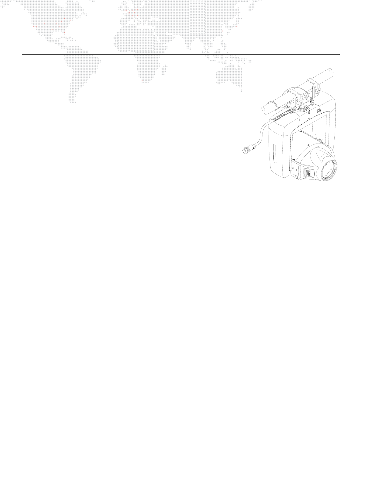
The VL6C+ Spot Luminaire from PRG Lighting is an improved version of the
VARI
❋LITE VL6C Spot Luminaire. Upgrades to the ventilation and airflow
system provide superior reliability for all circuit boards and motors, while
upgraded wiring and connectors further enhance the dependability and
consistency of all motors and pan/tilt mechanisms. Improvements to the
luminaire’s ignitor technology reduce hot restrike time from 8 minutes (VL6C)
to 1 minute (VL6C+) and a new lamp douse switch allows lamp power to be
quickly disconnected at the luminaire itself.
Like the standard VL6C model, it contains a 700 watt short arc lamp and a
cold mirror reflector to provide an extremely bright and flat field. The VL6C+
Luminaire accepts a wide variety of color filters and gobos. Two fixed wheels
are included, one factory configured for gobos and the second for color
filters. Automated zoom optics and edge control, along with a rotating gobo
wheel, compliment the fixed wheels and beam size iris functions for a wide
variety of effects. A standard palette of gobos and colors is provided with the
luminaire and custom gobos can also be installed.
The VL6C+ Luminaire can be controlled by PRG consoles or a wide variety of DMX512 consoles. Operation is
identical to the standard VL6C model.
Features:
+ A 700 watt arc source.
+ Rotatable, indexable gobos.
+ A 3:1 zoom optics assembly.
+ Variable beam focus to soften the edges of gobos or spots and provide gobo crossfades.
+ Full field dimmer to allow smooth timed fades and fast blackouts.
+ Mechanical iris for continuous beam size control with rapid beam size changes and smooth timed beam angle
changes.
+ Two, 12-position wheels, each providing 11 easily loaded positions (and 1 open) for interchangeable dichroic
color and gobo selections.
+ Low expansion glass reflector.
+ Solid state ignitor.
+ Hot restrike time of 1 minute.
+ Smooth, time-controlled continuous 360° pan and 270° tilt movement.
+ Control by PRG consoles or a wide variety of DMX512 consoles.
+ Compatible with Series 300 truss hooks for versatile hanging configurations.
+ Optional floor stand.
4 VL6C+ ™ SPOT LUMINAIRE USER MANUAL
Page 13

Upgrade Summary
The VL6C+ Spot Luminaire features many improvements over the standard VL6C Luminaire, both to the exterior and
interior components. The following is a complete summary of improvements found in the VL6C+™ Spot Luminaire:
+ Reduced luminaire head temperatures to improve reliability of the optical mechanisms by increasing air flow
through the head assembly. This improvement was accomplished by installing new air ducting, a metal foam air
filter and replacing an existing fan with a higher CFM fan.
+ Increased reliability of the lamp strike. This improvement was accomplished by installing a new solid state ignitor
and relocating it from a high temperature area in the head assembly to a low temperature area in the yoke. This
change also improves access to the ignitor and reduces hot restrike time from 8 minutes (VL6C) to 1 minute
(VL6C+).
+ Increased reliability of the Controller and Auxiliary PCBs. This improvement was accomplished by adding a
centrifugal blower to cool the PCB components and ventilation holes to improve air flow. The PCB RJ-45
connectors were also replaced with improved Molex interconnect cable assemblies.
+ Reduced PCB driver failures. This improvement was accomplished by installing a new 24VDC cable assembly to
protect the motor drivers from failing in the event the Yoke Termination PCB fuse blows.
+ Increased reliability of Pan and Tilt functions. This improvement was accomplished by retrofitting the pan/tilt
mechanisms with new clutches and encoders, replacing the pan/tilt cable assemblies and installing a newly
designed pan stop which prevents sticking.
+ Increased reliability of Yoke and Motor Cable Harnesses. This improvement was accomplished by designing new
harnesses with highly stranded 24AWG PVC wire which makes a more reliable connection in the MTA connectors.
+ Improved motor reliability and function. This improvement was accomplished by replacing the connectors on all
motors.
+ Improved yoke covers. This improvement was accomplished by installing new yoke sheet metal which not only
accommodates the relocation of PCB components, but adds support to the yoke covers which will prevent
damage to them during normal use. Ventilation holes have been added to the yoke leg for PCB cooling and air
flow, along with heavy duty yoke covers and new safety tethers to prevent covers from falling off.
+ Added reset switch. A "soft reset" can be accomplished using the new reset switch located in the yoke leg.
During a soft reset, the lamp will not be extinguished, eliminating the need to wait for the lamp to cool down
before restriking.
+ Added lamp douse switch to yoke cross-member. The switch should be used to douse the arc lamp before
disconnecting the pigtail cable. This will prevent damage to the contacts in the CPC connector, which can be
caused by drawing an arc during disconnect.
VL6C+ ™ SPOT LUMINAIRE USER MANUAL 5
Page 14
COMPONENTS
Exterior Components
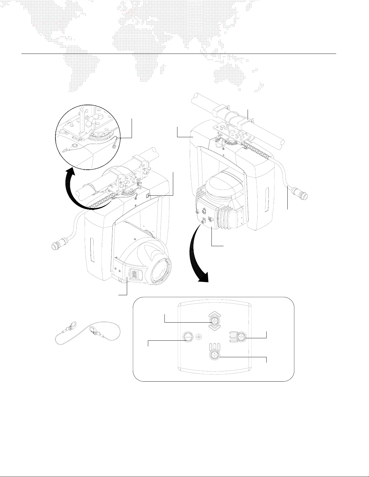
The following illustration shows the exterior VL6C+ components and controls.
Yoke Leg
Safety Cable
Yoke
Assembly
Lamp
Douse
Switch
Series 300
Truss Hook
Pigtail
Cable
Head Assembly
Hanging Safety Cable
Lamp Adjustment Controls
Focus
Captive Knob
for lamp access
(does not adjust
beam)
Figure 1-1: Exterior Components
Removable Lamp Assembly
(to access lamp for replacement)
Horizontal
Vertical
6 VL6C+ ™ SPOT LUMINAIRE USER MANUAL
Page 15
Interior Head Components
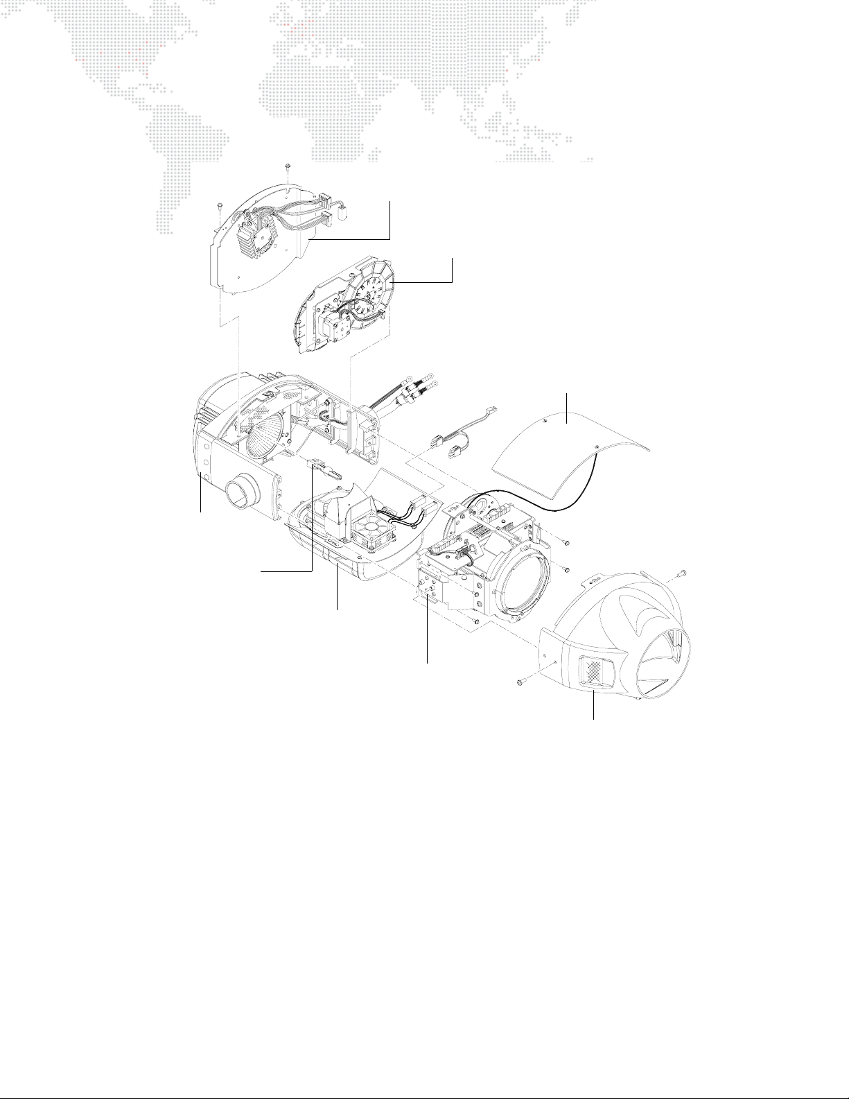
The following illustration shows the major sub-assemblies located in the VL6C+ Head.
Dimmer Bulkhead
Dim
Iris/Gobo/Color Bulkhead
Removable Top Cover
Rear Assembly
Lamp
Cover Assembly
Front Assembly
Contains Lens Barrel,
Yoke Termination Board,
and Rotating Gobo Wheel
Front Cover Assembly
Figure 1-2: Head Components
VL6C+ ™ SPOT LUMINAIRE USER MANUAL 7
Page 16

The luminaire’s fixed color and gobo wheels have twelve (12) positions, while the rotating gobo wheel has six (6)
positions. You can mix color filters and gobos on the same wheel, or have all filters on one wheel with all gobos on the
other wheel. VL6C+ Spot Luminaires are shipped in a standard configuration with all gobos on the front wheel (Wheel
1) and all color filters on the rear wheel
(Wheel 2).
Color and gobo wheels can be placed on any step position of the motor. Wheel positions are mapped to DMX512
fader positions to control 96 static positions and five (5) spin speeds. Percent values of 0 to 95 control static
positions; values 96 through 100 control spin speeds.
Standard Colors (Wheel 2) Standard Gobos (Wheel 1) Rotating Gobo Wheel
0 Open 0 Open 0 Open
1 0240 Light Red 1 7002 Pebbles 1 8005 4 Facet Prism
2 0850 Dark Blue 2 7025 Dust Breakup 2 6011 Circle of Ovals
3 0540 Yellow 3 6001 Medium Circle 3 4316 Hypno Spiral
4 0820 Lt. Blue Green 4 5011 Night Sky 4 6990 Spiral Stones
5 0150 Cool Pink 5 5501 Leaves 5 4305 Pinwheel
6 0660 Green 6 4202 Vertical Bars
7 0020 Magenta 7 7008 Waves
8 0960 Deep Lavender 8 7015 Block Breakup
9 0320 Flesh Pink 9 5523 Tribal Breakup
1
0440 Orange
0
1
0990 Congo Blue
1
1
5009 Liquid Texture
0
117029 Alpha Rays
8 VL6C+ ™ SPOT LUMINAIRE USER MANUAL
Page 17
Interior Yoke Components
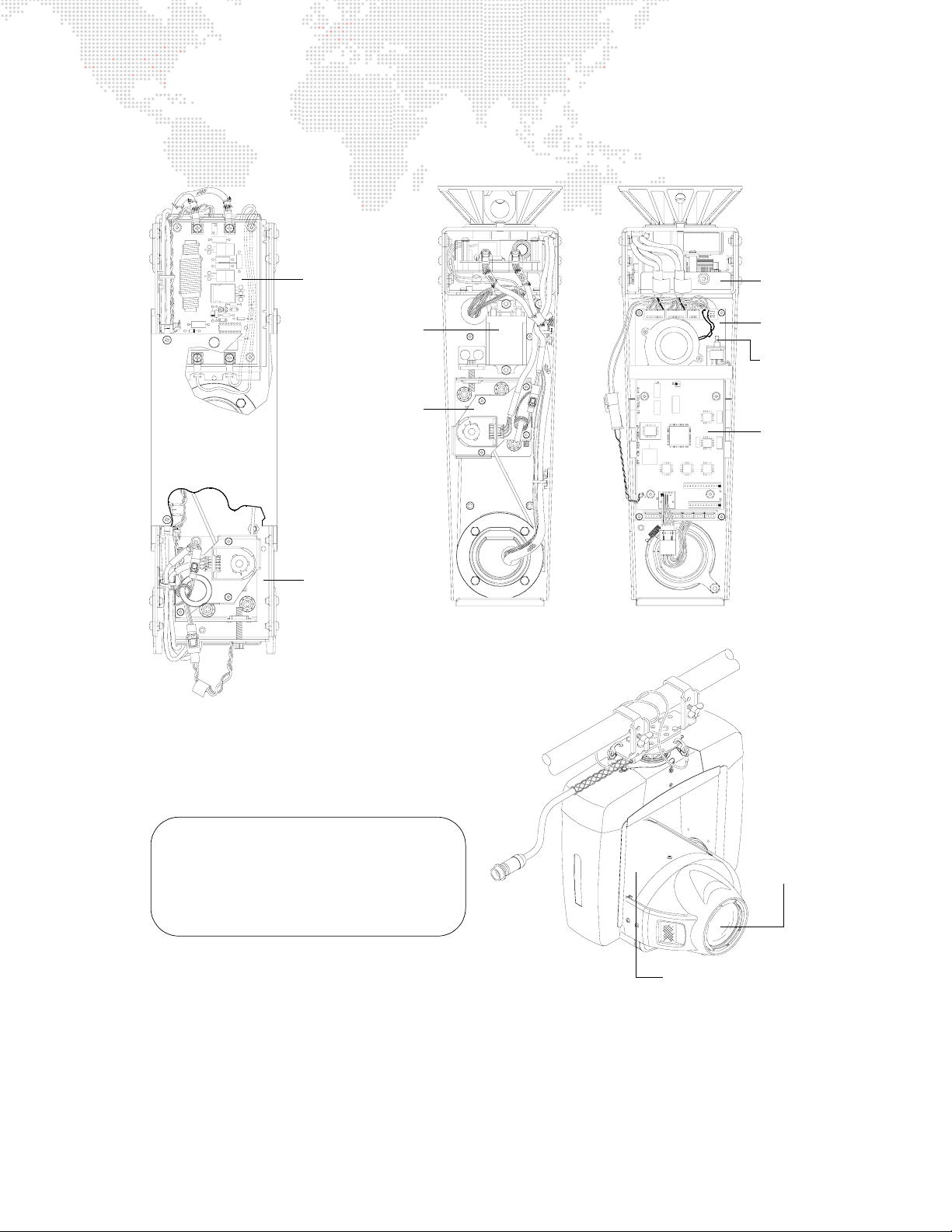
The following illustration shows the major sub-assemblies located in the VL6C+ Yoke.
YOKE TOP VIEW
Ignitor
PCB
Tilt
Mechanism
Pan
Mechanism
Relay
Pan
Mechanism
Main
Controller
PCB
Reset
Switch
Aux
Controller
PCB
TILT-SIDE YOKE LEG BOARD-SIDE YOKE LEG
To determine which yoke leg is which, without
having to remove the covers:
Position the luminaire so that you are facing the front
with the removable top cover facing up. The tilt-side
yoke leg is to the right; the board-side yoke leg is to
the left.
Figure 1-3: Yoke Components
TILT-SIDE
YOKE LEG
Front Lens
BOARD-SIDE
YOKE LEG
Removable Top Cover
VL6C+ ™ SPOT LUMINAIRE USER MANUAL 9
Page 18

Replacement Items and Accessories
The following items can be ordered from PRG. (Please order by PRG part number.)
PRG P/N Accessory
71.2528.0700.0 MSR 700W Lamp
22.9634.0145 Series 300 Safety Cable
22.9634.0161 Series 300 Floor Stand
22.9634.0195 Series 300 Third-Point Truss Hook
22.9634.0217 Series 300 Double Truss Hook
25.7042.0006 6 ft. Shielded Series 300 Lamp Cable
25.7042.0012 12 ft. Shielded Series 300 Lamp Cable
25.7042.0020 20 ft. Shielded Series 300 Lamp Cable
25.7155.0050 50 ft. Shielded Series 300 Lamp Cable (Smart Lamp Plus)
25.7155.0100 100 ft. Shielded Series 300 Lamp Cable (Smart Lamp Plus)
25.7155.0XXX Custom Length Shielded Series 300 Lamp Cable *
20.9623.0111 Smart Repeater Unit
20.9623.0600 Smart Repeater Plus Unit
22.9620.0217 Series 200 Truss Hook (2 each required for Smart Repeater)
20.9625.0024 Series 300 Molded Plastic Work Trunk
20.9625.0112 Luminaire Case
* Cannot exceed 200 ft. in length.
10 VL6C+ ™ SPOT LUMINAIRE USER MANUAL
Page 19
OPERATION OVERVIEW
External Power and Data Configuration
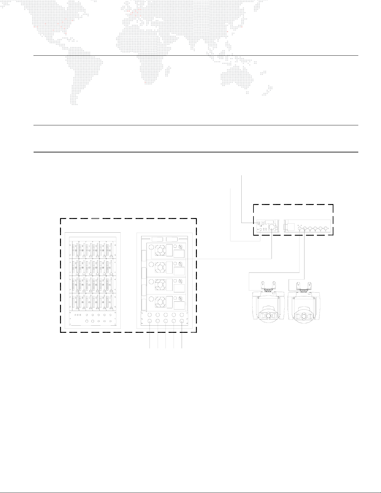
Control data signals, 24Vdc, and lamp power are provided by a Series 300 Smart Repeater or Smart Repeater Plus
processing unit to Series 300 luminaires via lamp cables. A maximum of three (3) VL6C+ Luminaires may be powered
from a Smart Repeater unit and a maximum of six (6) VL6C+ Luminaires from a Smart Repeater Plus unit. Lamp power
for VL6C+ Luminaires is provided by APS6 power supply modules located in a Series 300 Modular Rack. The
following diagram shows how data and power are distributed to VL6C+ Luminaires in a sample DMX512 system.
Note: Refer to the VARI❋LITE Interface Devices Service Manual (02.5014.0010), VARI❋LITE Series 300 Modular
Rack Service Manual (02.9640.0010) and Controlling VARI
(02.3004.0300.52) for more information about the associated equipment.
Series 300 Modular Rack
w/ APS6 Power Supply Modules
FRONT REAR
❋LITE Equipment Using a DMX512 Console Manual
DMX512 From Console
AC Power
Series 300 Smart Repeater
or Smart Repeater Plus Unit *
FRONTSIDE
Series 300
APS Trunk Cable
Power Input
120/208 Volt
3Ø AC Line
(Lamp Power)
*
A maximum of three (3) VL6C+ Luminaires may be
powered from a Smart Repeater unit and a maximum
of six (6) VL6C+ Luminaires from a Smart Repeater
Plus unit.
Series 300 Lamp Run
VL6C+ VL6C+
Figure 1-4: Power and Data Configuration (Typical DMX512 System)
VL6C+ ™ SPOT LUMINAIRE USER MANUAL 11
Page 20

Smart Repeater Units
The Smart Repeater processing units combine electrical power and data signals from different sources and provide it
for up to six VL6C+ Spot Luminaires via a single connector to each luminaire.
Smart Repeater features:
+ Receives Virtuoso® or Series 200 data signal, and AC power for electronics through standard, 9-pin Series 200
lamp cable from ACS rack and sends it to connected luminaires.
+ Receives lamp power from conventional dimmers or APS6/C3 power supply modules through standard Socapex-
type 19-pin lighting connector and sends it to connected luminaires.
+ Provides a thumbwheel switch for setting the starting address for the six luminaire outputs.
+ Provides Broadcast and Reply LEDs to monitor data traffic.
+ Contains test software for Series 300 luminaires.
+ Attaches to truss or pipes with two truss hooks and a safety cable.
+ Operates up to six VARI
+ Operates VL6C+ Luminaires on a limited basis. When using multiple combinations involving the VL6C, use the
point system indicated below. Combinations of luminaires connected to the Smart Repeater unit should not
exceed 6 points.
VL5 = 1 point
VL5Arc = 1 point
VL6 = 1 point
VL6B = 2 points
VL6C / VL6C+ = 2 points
+ Accepts DMX512 protocol from DMX control desks and translates it to Series 300 comm for DMX control of
VARI
❋LITE luminaires.
Two versions of the unit are available: a standard Smart Repeater unit and a Smart Repeater Plus unit. The standard
unit can operate any of the Series 300 luminaires with the exception of the VARI
luminaires, which can only be operated with a Smart Repeater Plus unit.
❋LITE VL5, VL5Arc, VL5B, VL6, or VLM luminaires; one on each output connector.
❋LITE VL7, VL7B, and VL7U
Smart Repeater Plus Unit
The Smart Repeater Plus unit has the ability to operate all Series 300
luminaires including the VL7 series spot luminaires, which require
additional power not available with the standard Smart Repeater unit.
Operation and functionality of the Smart Repeater Plus unit is identical
to the standard unit, with the addition of an active DMX512 termination
switch and fan cooling. The Smart Repeater Plus unit can control up to
six VL7, VL7B or VL7U luminaires.
12 VL6C+ ™ SPOT LUMINAIRE USER MANUAL
Page 21
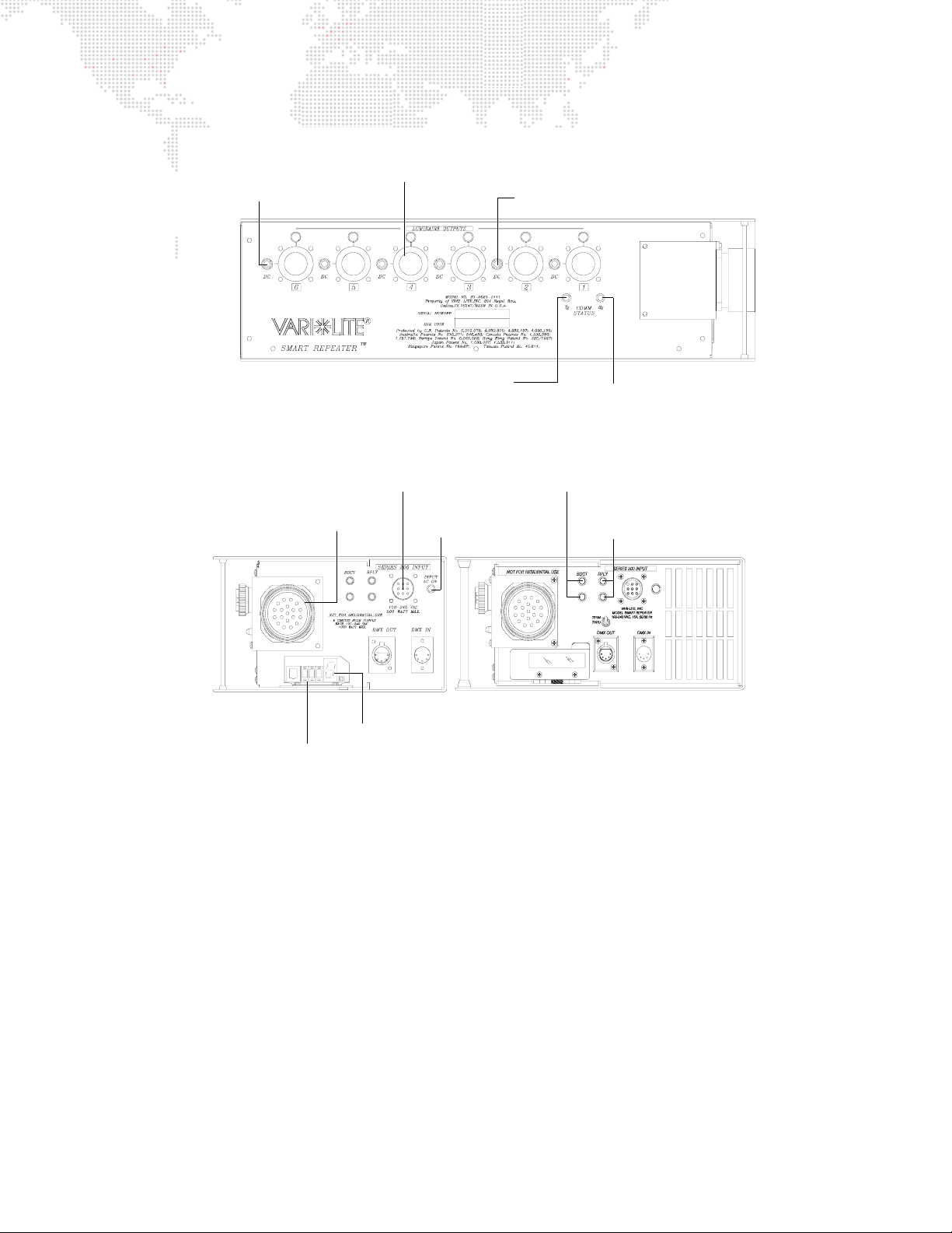
Circuit breaker protection
for each output connector
10A 10A 10A 10A 10A 10A
Output connector providing
power and signal to individual luminaire
via luminaire lamp cable
Neon lamp power indicator for each output
FRONT VIEW
Trunk Cable Connector
(Socapex) receives lamp
power from dimmers and Mod
Racks, and S300 Trunk Cable
SMART REPEATER
SIDE VIEW
Thumbwheel Switch
sets start address
for six output addresses
to luminaires
Red Transmit LED
indicates valid data
between Repeater
and luminaires
Series 200 Lamp
Cable Data Input
AC Input
Indicator
Eight-Segment Display
indicates whether DMX512
is present and current DMX
operating mode
Red Response LED indicates
valid data between Repeater
and luminaires
Red and Green Broadcast LEDs
indicate valid Virtuoso comm between
Repeater and NIF unit
Red and Green Reply LEDs
indicate valid Virtuoso comm
between Repeater and NIF unit
SMART REPEATER PLUS
SIDE VIEW
Figure 1-5: Smart Repeater / Smart Repeater Plus Input/Output Connections
VL6C+ ™ SPOT LUMINAIRE USER MANUAL 13
Page 22
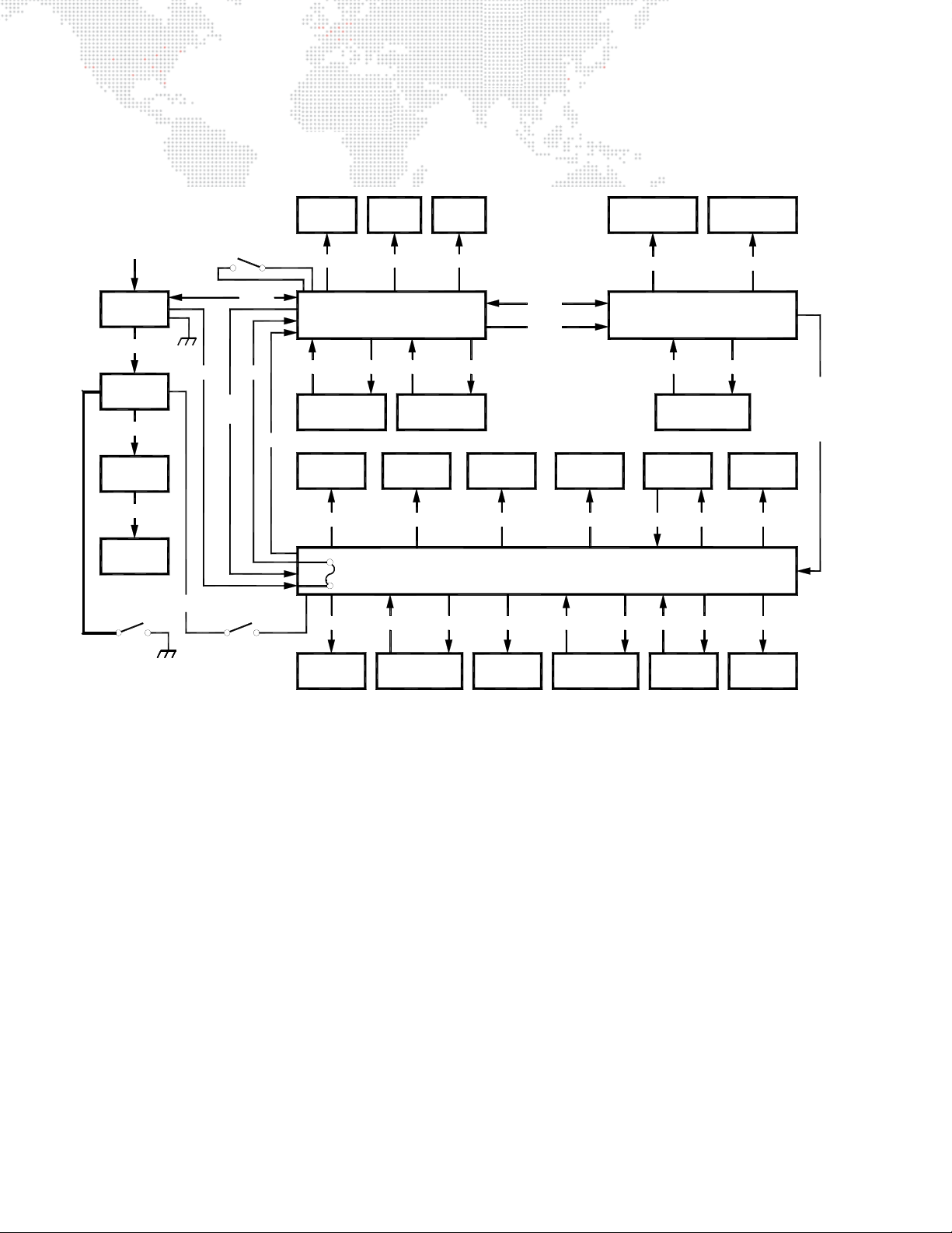
Internal Power and Data Distribution
The following diagram shows how data and power are distributed within the VL6C+ Spot Luminaire.
S300 LAMP
RUN FROM
SMART
REPEATER
INPUT
PIGTAIL
LAMP POWER
RELAY
PCB
LAMP
A
+
B
-
LAMP POWER
IGNITOR
LAMP POWER
BACKCAP
SAFETY
INTERLOCK
+24V
+24V
RESET
SWITCH
MOTOR
DRIVE
LAMP
DOUSE
DATA
+24V
SENSORS
BLOWER
FAN
+24V
MAIN CONTROLLER PCB
DATA
PAN
ENCODER
EDGE
MOTOR
DRIVE
DRIVE
PAN
MOTOR
DRIVE
+5V DATA +5V
MOTOR
+24V
7A FUSE
SENSE
TILT
MOTOR
DRIVE
DATA
+24V
TILT
ENCODER
ZOOM
DRIVE
BEAM
MOTOR
DRIVE
YOKE TERMINATION PCB
24-9660-0515
+5V SENSE +5V SENSE +5V
DRIVE
DIMMER
GOBO WHEEL
MOTOR
DRIVE
ROTATING
DRIVE DRIVE
AUX CONTROLLER PCB
24-9803-065024-9803-0600
SENSE +5V
ROT GOBO
SENSORS PCB
THERMAL
SENSOR
OT
ROTATING
GOBO INDEX
+24V
60MM
AXIAL FAN
+24V
+24V
ZOOM
AND
EDGE
MOTOR
DRIVE
GND
WHEEL 1
MOTOR
WHEEL 1
SENSOR PCB
WHEEL 2
MOTOR
WHEEL 2
SENSOR PCB
Figure 1-6: Internal Power and Data Distribution
DIMMER
SENSOR
AXIAL FAN
80MM
14 VL6C+ ™ SPOT LUMINAIRE USER MANUAL
Page 23

2.
INSTALLATION
This chapter contains instructions for hanging or floor mounting the luminaire and connecting it to the
system.
+
MOUNTING THE LUMINAIRE
+ SYSTEM CONNECTION
Page 24
MOUNTING THE LUMINAIRE
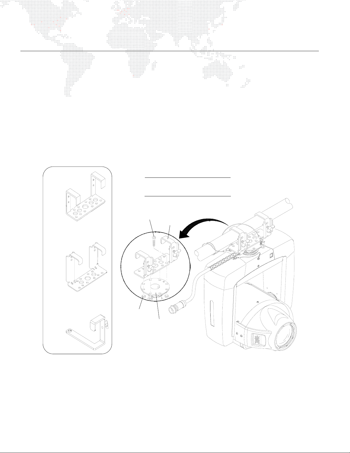
Attaching a Truss Hook
The VL6C+ Spot Luminaire can be hung horizontally or vertically from any structure designed to accommodate the
load created by this moving luminaire. In standard hanging applications, the VL6C+ Luminaire utilizes a Series 300
double truss hook, which is bolted to the pan tube. The hook can be oriented in 45 degree increments to provide
flexible mounting. (See "Standard Hang" on page 17.)
A special third-point truss hook, which mounts to the pan tube in addition to the double hook, is available to provide a
third point of support. (See "Three-Point Hang" on page 19.)
To attach a double truss hook:
Step 1. Determine type of installation and required orientation of truss hook.
Step 2. At pan tube, attach truss hook using four 5/16-18 x 1" bolts and 5/16-18 nuts (Figure 2-1).
Step 3. Ensure truss hook is secure.
Old Style
S300 Double Hook
5/16-18x 1" Grade 5
Bolt (53.7001.0003)
NOTE:
Use four 5/16-18 x 1" Grade 5 Bolts when
installing a Series 300 Double Truss Hook.
Truss
Hook
New Style
S300 Double Hook
(22.9634.0217)
S300 Third-Point
Truss Hook
(22.9634.0195)
5/16-18 Nut
w/ Nylon Insert
(53.2025.0002)
Pan Tube
Figure 2-1: Attaching a Truss Hook
16 VL6C+ ™ SPOT LUMINAIRE USER MANUAL
Page 25
Hanging Methods
Standard Hang
In standard hanging applications, the VL6C+ Spot Luminaire utilizes a Series 300 double truss hook, which is bolted
to the pan tube and affixed to square tube or round pipe; the minimum outside dimension for a piece of pipe or tube
is 1 inch (2.54 cm) and the maximum outside dimension is 2 inches (5.08 cm).
CAUTION: Wing bolts should be tightened only by hand. Do not use wrenches or other tools as this can
damage the truss or the hook.
WARNING: A safety cable MUST be used in all hanging configurations.
Step 1. Lift luminaire into mounting position (Figure 2-2 on next page).
Step 2. Tighten truss hook wing bolts by hand. Ensure that luminaire is fully supported.
Step 3. Install safety cable as follows (referring to Figure 2-2 DETAIL A):
a. Attach one end of safety cable to pan tube.
b. Loop several times around truss or pipe, leaving as little slack as possible.
c. Attach other end of safety cable to pan tube.
Step 4. Connect input pigtail cable to Series 300 Lamp Run Cable which is connected to a Smart Repeater or
Smart Repeater Plus unit. (Refer to "External Power and Data Configuration" on page 11 for an example
system diagram.)
VL6C+ ™ SPOT LUMINAIRE USER MANUAL 17
Page 26
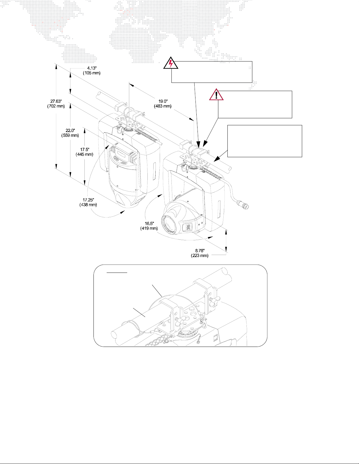
A Safety Cable MUST be used
for all hanging installations and
may be required by local codes.
Safety cable and input pigtail
cable must be dressed to
avoid interference with
luminaire motion.
Square tube or round pipe.
Minimum outside dimension for
pipe or tube is 1 inch (2.54 cm).
Maximum outside dimension is
2 inches (5.08 cm)
DETAIL A
Safety Cable
Pipe or Tube
Figure 2-2: Standard Hanging Configuration and Clearances
18 VL6C+ ™ SPOT LUMINAIRE USER MANUAL
Page 27
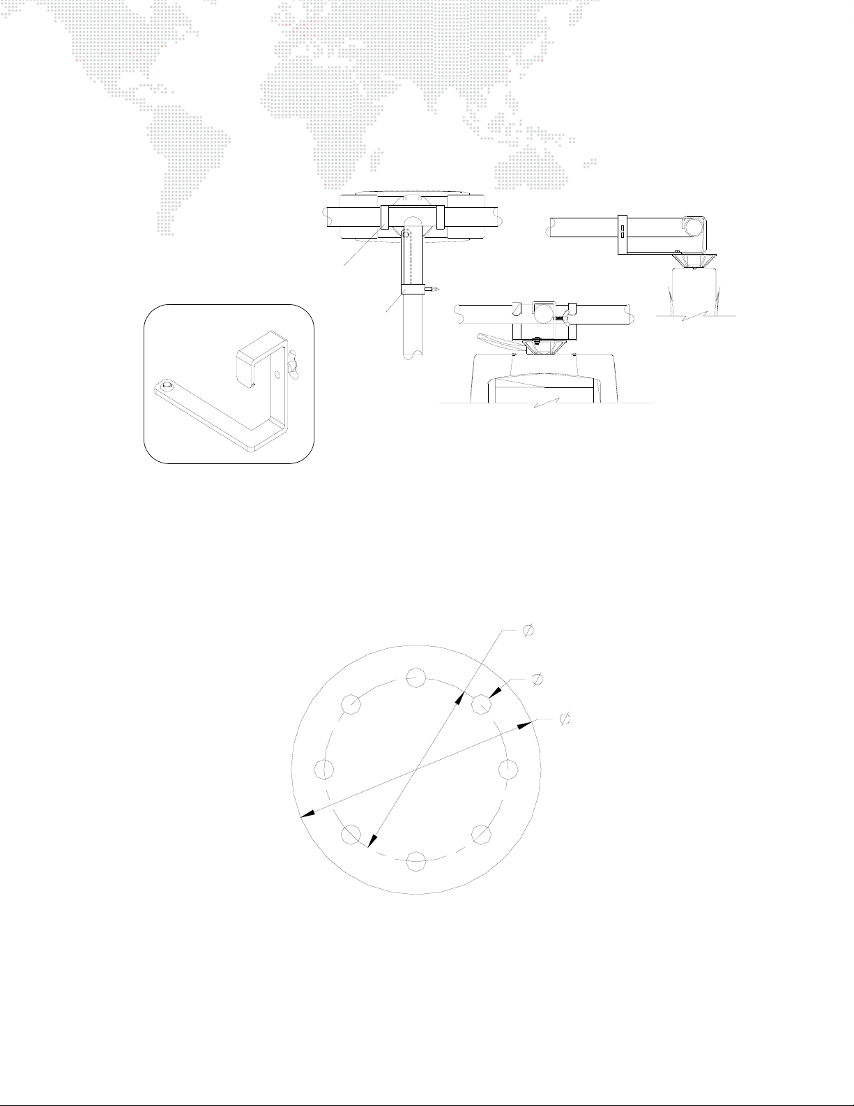
Three-Point Hang
A Series 300 third-point truss hook can be used to stabilize the luminaire in a three-point hanging configuration. The
third-point hook is bolted to the pan tube in addition to the standard double hook. The following illustration shows
how the hook is used to achieve a three-point hang.
Series 300
Double Hook
S300 Third-Point
Truss Hook
(22.9634.0195)
Third-Point
Hook
Figure 2-3: Three-Point Hang
Custom Hang
The luminaire can also be hung using custom hanging devices. The pan tube's multiple mounting holes allow flexibility
for placement of hardware. To attach custom hanging devices to the pan tube, the following hardware can be used:
+ 5/16"-18 x 1" HSCZ Grade 5 Bolt (53.7001.0003)
+ 5/16"-18 Zinc nut with nylon inserts (53.2025.0002)
Pan Tube Top View
4.055 in
103 mm
0.375 in
9.5 mm
4.67 in
119 mm
Figure 2-4: Pan Tube Hole Dimensions
VL6C+ ™ SPOT LUMINAIRE USER MANUAL 19
Page 28
Floor Mounting
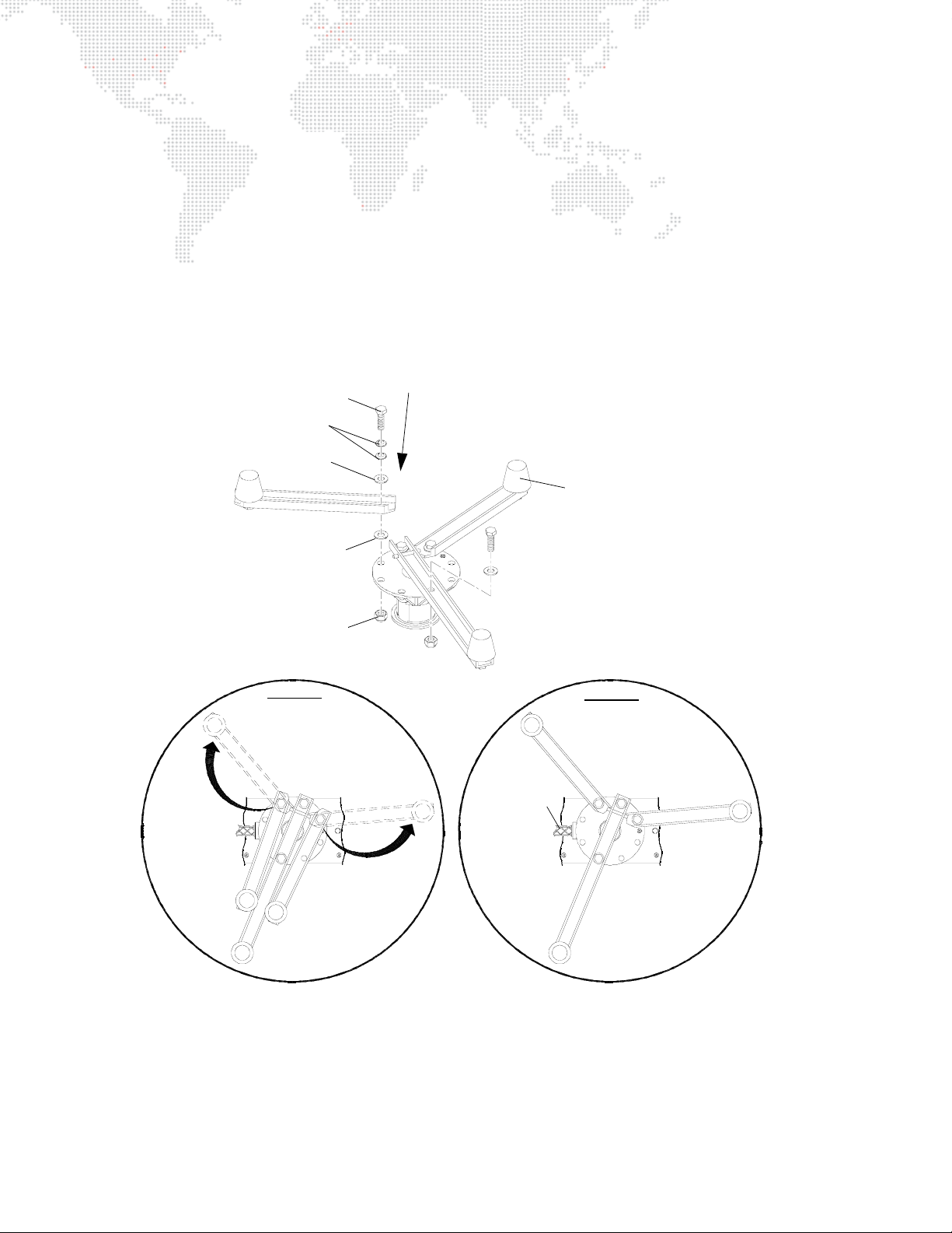
The VL6C+ Spot Luminaire may be mounted in an upright floor position using a Series 300 floor stand. The floor stand
(22.9634.0161) includes all necessary hardware as shown in Figure 2-5.
To install floor stand:
Step 1. Orient pigtail cable as shown in Figure 2-5 DETAIL B and rotate pan tube accordingly.
Step 2. Secure pivoting legs to pan tube using, on each pivoting leg, one 5/16-18 bolt and nut; with two clutch disc
springs, and one 1/4" flat washer between the bolt and the leg, one 1/4" flat washer between the leg and
the pan tube.
Step 3. Tighten nuts and bolts until there is proper tension: just enough so pivoting legs stay in place, but not so
much that the legs don’t pivot. See Figure 2-5 DETAIL A.
5/16-18 x 1" Grade 5 Bolt (one per leg)
1/4" Flat Washer (two per leg)
Be sure to install disc springs with concave surfaces facing the flat washer.
Disc springs should be installed
with concave surfaces facing down
Clutch Disc Spring
(2 per pivoting leg)
PIVOTING LEG
1/4" Flat Washer (two per leg)
S300 Floor Stand Assembly
(22.9634.0161)
PIVOTING LEG
Rubber Bumper (3)
5/16-18 Nut w/ Nylon
Insert (one per leg)
DETAIL A
Pivoting legs should
be installed so that
they pivot, yet stay in
place after opening
PIVOTING LEG
PIVOTING LEG
FIXED LEG
FIXED LEG
Pigtail Cable
FIXED LEG
DETAIL B
PIVOTING LEG
PIVOTING LEG
Figure 2-5: Installing Floor Stand
Step 4. Place luminaire in desired floor position. Refer to clearances in Figure 2-6.
Step 5. Connect input pigtail cable to Series 300 Lamp Run Cable which is connected to a Smart Repeater or
Smart Repeater Plus unit. (Refer to "External Power and Data Configuration" on page 11 for an example
system diagram.)
20 VL6C+ ™ SPOT LUMINAIRE USER MANUAL
Page 29
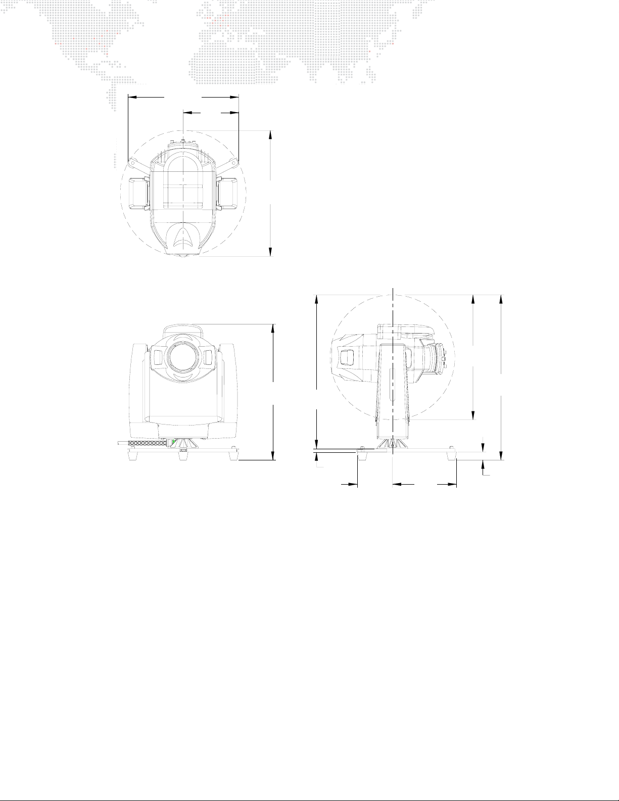
16.87"
(428 mm)
8.43"
(214 mm)
19.0"
(482 mm)
C
L
19.0"
(482 mm)
20.71"
(526 mm)
23.40"
(594 mm)
(13 mm)
0.53"
5.40"
(137 mm)
Figure 2-6: Floor Mounting Clearances
C
L
9.72"
(247 mm)
25.13"
(638 mm)
1.25"
(32 mm)
VL6C+ ™ SPOT LUMINAIRE USER MANUAL 21
Page 30
SYSTEM CONNECTION
Connecting to System (Typical)
The VL6C+ Spot Luminaire requires a Smart Repeater unit for power and control by DMX512 consoles. (Refer to
"Smart Repeater Units" on page 12 of the Operation Overview section.) Lamp power is provided by an APS6 power
supply module installed in a Series 300 Modular Rack.
WARNING: Voltages high enough to injure or kill a person exists in the AC power rack when power is
applied. Verify that power has been removed from the AC rack before reconfiguring bus bars or performing
other internal work.
Three-Phase Power Source
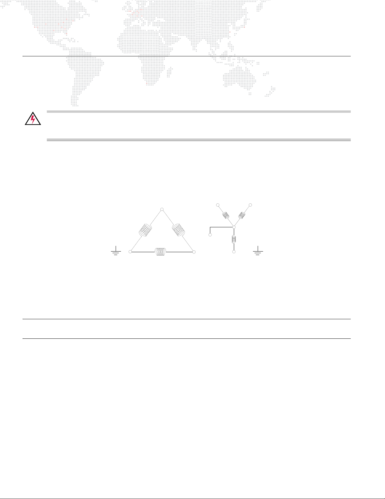
The system is commonly connected to a three-phase AC power source. Three-phase AC power is produced by
alternators which contain three separate windings designed so that the voltages induced in them are equal in
amplitude and out of phase with each other by exactly 120 degrees. The outputs can be connected in one of two
methods to produce a three-wire, three-phase circuit: wye-connected source and the delta-connected source.
EARTH
GROUND
Y
DELTA SERVICE
(NO NEUTRAL USED)
X
X
NEUTRAL
Z
WYE SERVICE
(FIVE WIRE)
Z
Y
EARTH
GROUND
Figure 2-7: Three-Phase Power Diagram
In almost all cases the power source (house service) will be wye connected, but Series 200/300 equipment may be
connected either as delta or wye loads as required. The most obvious difference between delta and wye loads is that
a wye load uses a neutral and a delta load does not.
Note: The Series 200 powered outputs on the modular rack utilize the service neutral, and therefore must not be
used with a delta service, and requires the presence of a neutral, even when connected as a delta load.
22 VL6C+ ™ SPOT LUMINAIRE USER MANUAL
Page 31

There are five connections for a wye source and four connections for a delta source. Cables are often color coded to
represent corresponding connections.
Table 2-1: Delta/Wye Connections
Delta Power * Wye Power
Connection
Phase X
Phase Y
Phase Z
Neutral
Ground
US
Color Code
Black Gray Black Gray
Red Black Red Black
Blue Brown Blue Brown
N/A N/A White Blue
Green Green Green Green
UK
Colour Code
US
Color Code
UK
Colour Code
* Not applicable in Europe.
Input Voltage
When the system is configured for delta operation, the input voltage to the luminaires equals the phase-to-phase
voltage of the power source. When the system is configured for wye operation, the input voltage to the luminaires
equals the phase-to-neutral voltage of the power source. Single-phase power can be used to operate the system by
configuring the equipment for wye operation and connecting all three phase inputs to the same single-phase source.
APS6 modules usually operate under three-phase power, but can also be operated under 180-240 VAC, single phase
mains with L1, L2, and L3 tied together at the SixPack chassis.
Typical wye services in the United States produce voltages ranging from 175 to 225 VAC phase-to-phase and 90 to
130 VAC phase-to-neutral. The SixPack Chassis and the ACS rack should be placed in delta mode so that the racks
produce 175 to 225 VAC to the system. AC for the system is produced across the phases.
In Europe, wye services produce voltages ranging from 310 to 415 VAC phase-to-phase and 180 to 240 VAC phaseto-neutral. Since the system can not operate in voltages above 260 VAC, the SixPack Chassis and ACS rack must be
placed in wye mode, thus activating the neutral and placing the system into the standard 180 to 240 VAC operating
range.
VL6C+ ™ SPOT LUMINAIRE USER MANUAL 23
Page 32
Configuring Modular Rack and APS6 Modules
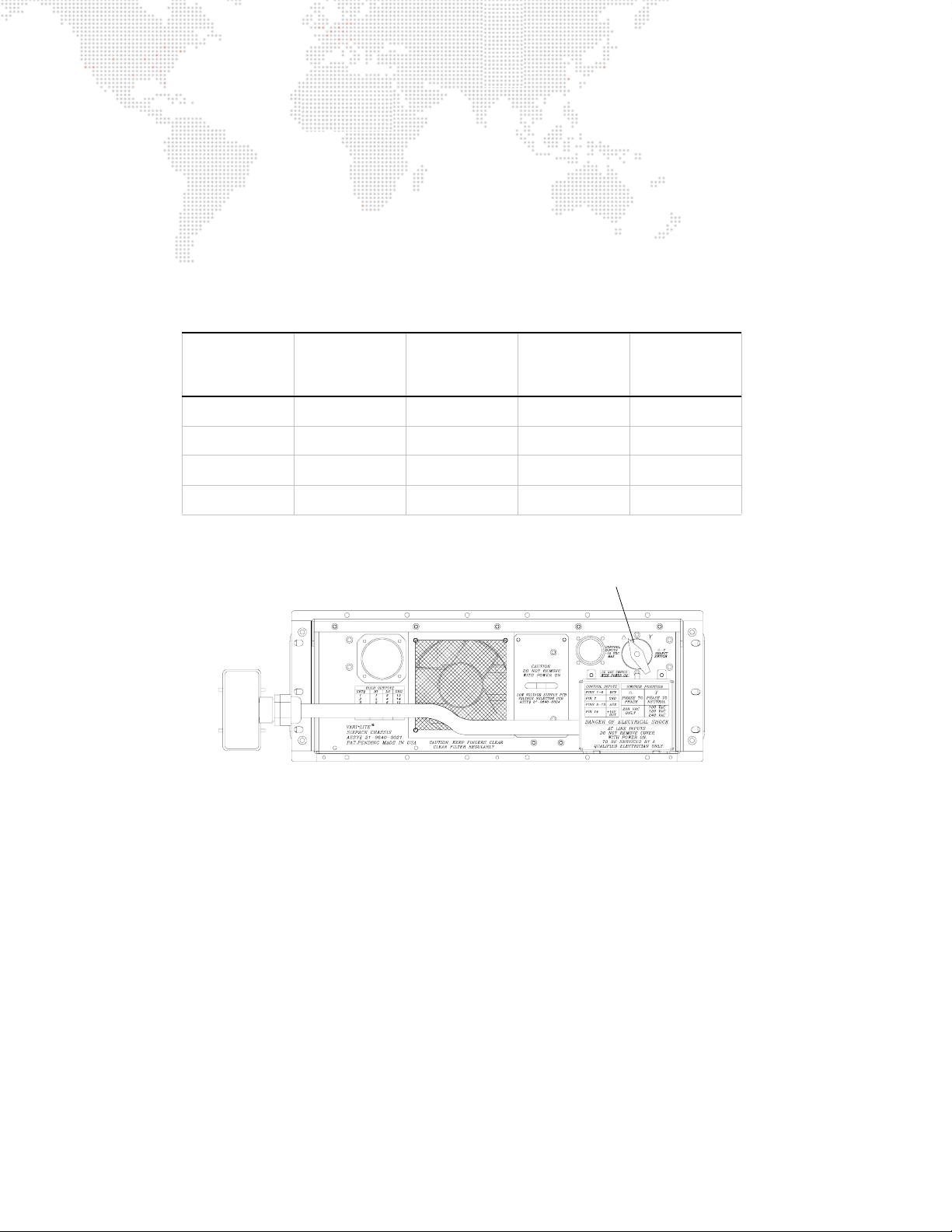
Set Modular Rack SixPack chassis delta/wye switch(es) to correct setting:
Determine requirements for either delta or wye load.
+ While operation as a delta load is typical in the U.S., most European countries require the system to be configured
as a wye load. For example, if the house service is a wye-connected source and the phase-to-neutral voltage is
220, the system must be configured as a wye load.
+ Also note that if line voltage is 120 phase-to-neutral, the system must be configured as a delta load. If line voltage
is 220 phase-to-neutral, the system must be configured as a wye load.
Table 2-2: Requirements For Delta and Wye Loads
Ty pe
Wye
Wye
Delta
Single Phase
VAC
Phase to
Neutral
100-130 175 - 225 Delta 175 - 225
180 - 240 310 - 415 Wye 180 - 240
- 180 - 240 Delta 180 - 240
180 - 240 - Wye 180 - 240
VAC
Phase to
Phase
At rear of SixPack chassis, set switch to required setting (Figure 2-8).
SIXPACK CHASSIS REAR VIEW
Figure 2-8: Series 300 Modular Rack SixPack Chassis
Delta/Wye
Jumper
Position
Delta/Wye Switch
Voltage
to
Modules
24 VL6C+ ™ SPOT LUMINAIRE USER MANUAL
Page 33
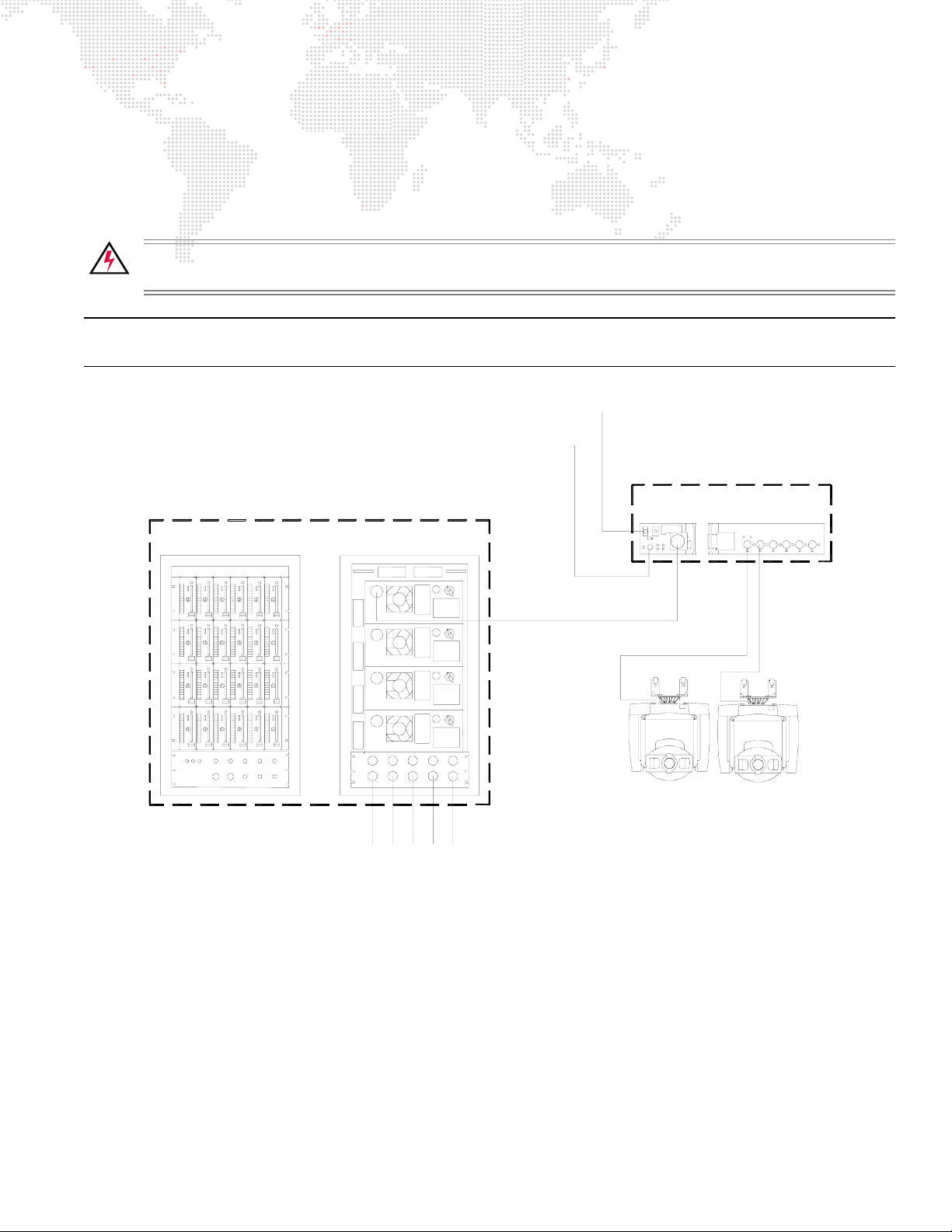
Connect Series 300 Modular Rack to power source:
Three-phase power will need to be supplied to the system. The maximum recommended Modular Rack power
requirement is 200 amps, using 2/0 feeder with 4/0 Cam-Lok connectors and a 200A line disconnect. A SixPack
Chassis requires 30 amps, and uses Hubbell or Epic connectors on 8/5 multicore cable. Connector choice is
dependent upon location. This cable will need to be run from a house disconnect through a 30A line disconnect to the
racks.
WARNING: The high voltages required to run this equipment are dangerous. Electrical "tie-ins" should be
handled by a qualified electrician.
Note: Some equipment in Europe will work using single-phase power. Check with an Account Manager regarding
your event.
DMX512 From Console
AC Power
Series 300 Smart Repeater
or Smart Repeater Plus Unit *
Series 300 Modular Rack
w/ APS6 Power Supply Modules
FRONT REAR
FRONTSIDE
Series 300
APS Trunk Cable
Power Input
120/208 Volt
3Ø AC Line
(Lamp Power)
*
A maximum of three (3) VL6C+ Luminaires may be
powered from a Smart Repeater unit and a maximum
of six (6) VL6C+ Luminaires from a Smart Repeater
Plus unit.
Series 300 Lamp Run
Figure 2-9: Power and Data Configuration (Typical)
VL6C+ VL6C+
VL6C+ ™ SPOT LUMINAIRE USER MANUAL 25
Page 34
Configure APS6 module(s):
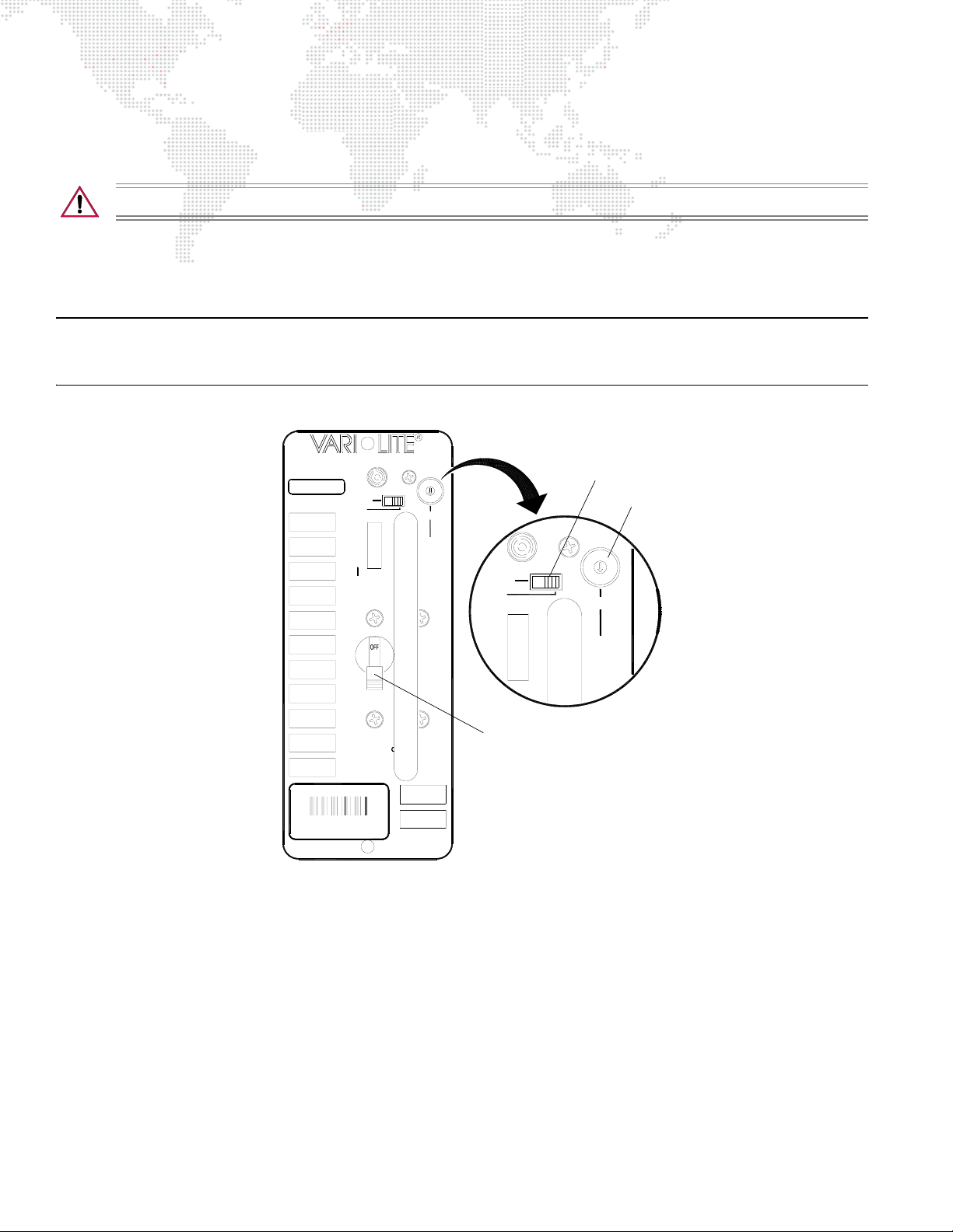
Lamp power for the VL6C+ Spot Luminaire is provided by an APS6 power supply module installed in a Series 300
Modular Rack.
CAUTION: Do not change mode or power setting with power applied to module.
Step 1. At face of APS6 module(s), set rotary power switch to the 700W position (Figure 2-10).
Step 2. Set mode switch to PSET for manual operation.
Step 3. Apply power to lamp by moving circuit breaker switch to the ON position.
Note: The PSET (Preset) mode enables manual control of the module. This is the normal mode of operation. The DCV
(Dimmer Control Voltage) mode operates the module with 0-10Vdc control input. This mode is only required when
using an SPC-36 controller to remotely control modules from a console.
APS 6
S300U-06
MODE
PRG
7257730
PRG
ARC
AC
ON
0
1
3
PSET
DCV
SHORT
DCV
IPRES
STATUS
2
POWER
0-400W
1-625W
2-700W
3-XXXW
O
O
A
O
WARNING:UNIT MU URNED
OFF BEFORE REM
DO NOT UNPLUG H
ENSURE THAT
BREAKER IS OFF
BEFORE
SELECTING POWER.
MODULE
Figure 2-10: APS6 Module
AC
ON
PSET
DCV
HORT
DCV
Circuit Breaker Switch
Mode Switch
Power Switch
0
1
3
2
POWER
0-400W
1-625W
2-700W
3-XXXW
Power Up the Luminaire:
Proceed to "Powering Up the Luminaire" on page 28 for further operating instructions.
26 VL6C+ ™ SPOT LUMINAIRE USER MANUAL
Page 35

3.
OPERATION
This chapter contains instructions for power-up, reset and lamp dousing, along with DMX512
mapping information required for controlling the luminaire.
+
POWER-UP PROCEDURES
+ SMART REPEATER MODES
+ DMX512 MAPPING
Page 36
POWER-UP PROCEDURES
Powering Up the Luminaire
When power is applied, the VL6C+ Spot Luminaire will begin a calibration sequence which moves its pan, tilt, and all
other mechanisms. After calibration, the luminaire head will either stop at its "home" position (which positions the pan
and tilt axis at mid-rotation) or move to its current DMX-defined position if DMX512 data is present. All other
mechanisms will also move to their "home" or DMX-defined positions.
CAUTION: Before applying power, be sure the luminaire is positioned so that the head and yoke can move
freely without restriction. Refer to the Installation chapter for complete setup instructions.
To power up:
Step 1. Apply power and data to Smart Repeater or Smart Repeater Plus.
Step 2. Allow luminaire to complete calibration sequence.
Step 3. The luminaire is now ready for operation. See "DMX512 Mapping" on page 32 for control parameters.
Note: Refer to "Proper Lamp Servicing and Operation" on page 43 for correct lamp operating procedures.
28 VL6C+ ™ SPOT LUMINAIRE USER MANUAL
Page 37
Soft Reset
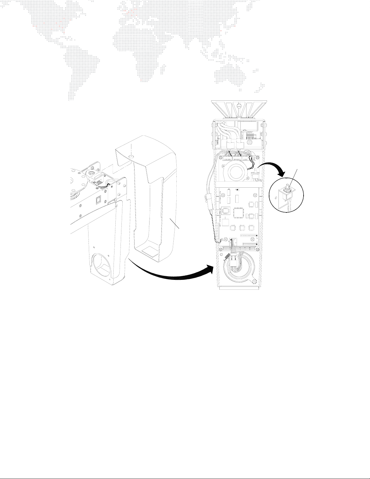
A "soft reset" can be accomplished using the reset switch located in the yoke leg. During a soft reset, the lamp will not
be extinguished, eliminating the need to wait for the lamp to cool down before restriking.
To perform a soft reset:
Step 1. Remove board-side yoke leg cover (Figure 3-1).
Reset
Switch
Yoke Leg
Cover
Figure 3-1: Accessing the Reset Switch
Step 2. Press reset switch.
Step 3. Allow luminaire to execute reset and calibration procedure.
Step 4. Replace yoke leg cover.
VL6C+ ™ SPOT LUMINAIRE USER MANUAL 29
Page 38
Lamp Douse Switch
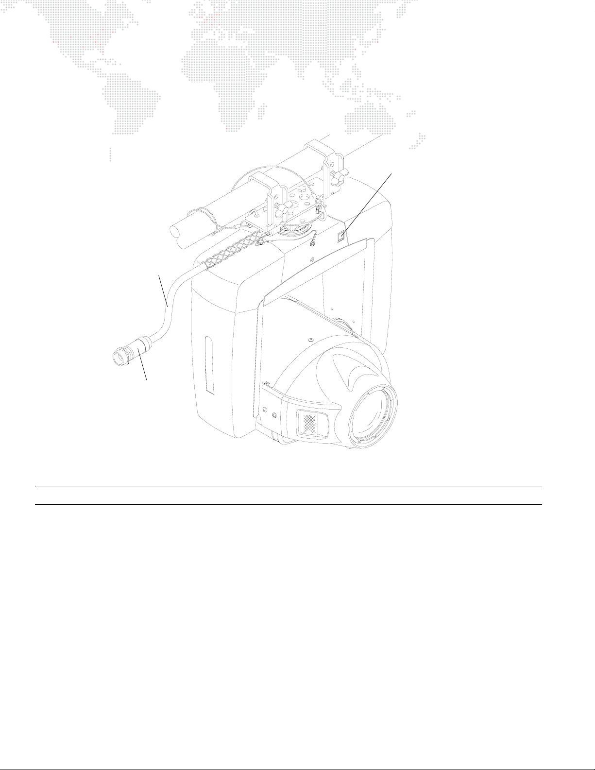
The lamp douse switch should be used to douse the arc lamp before disconnecting the pigtail cable. This will prevent
damage to the contacts in the CPC connector, which can be caused by drawing an arc during disconnect. To douse
the lamp, press the lamp douse switch located at the yoke cross-member.
Lamp Douse Switch
Pigtail Cable
CPC Connector
Figure 3-2: Lamp Douse Switch Location
Note: Refer to "Proper Lamp Servicing and Operation" on page 43 for correct lamp operating procedures.
30 VL6C+ ™ SPOT LUMINAIRE USER MANUAL
Page 39
SMART REPEATER MODES
Setting Smart Repeater DMX512 Modes
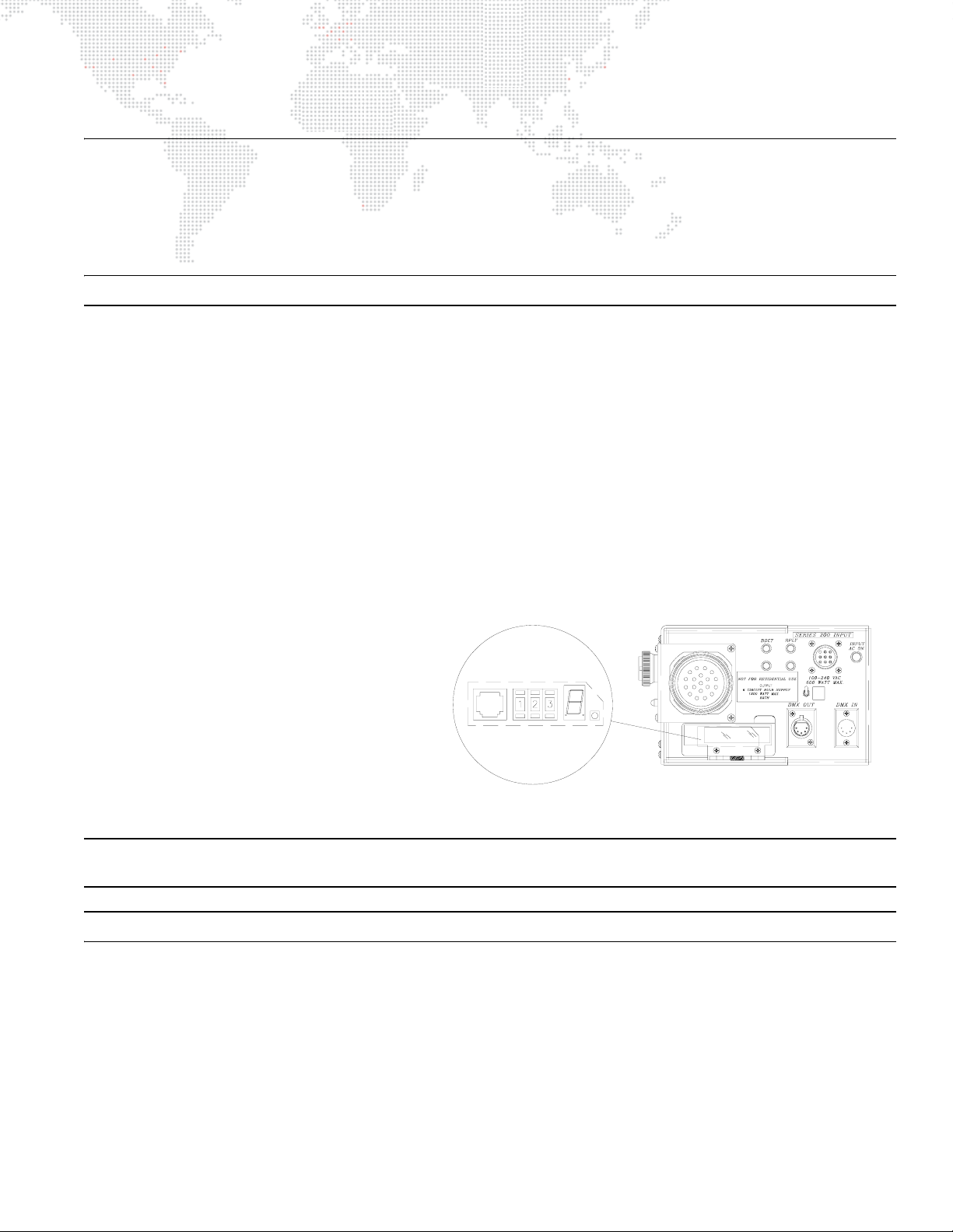
There are a total of ten (10) software modes available for use in the Smart Repeater or Smart Repeater Plus units,
allowing optimized control of the lighting system. Modes 5-10 apply to the VL6C+ Spot Luminaire. Below are brief
descriptions of the modes and how to access them.
Note: It is possible to have multiple modes in a single system, but not on a single Smart Repeater unit.
MODE 5: 16-Bit with Reset - To set Mode 5, set the thumbwheel to 905. Mode 5 requires 14 channels per luminaire
output port for a total of 84 channels per Smart Repeater unit.
MODE 6: Extended 16-Bit - To set Mode 6, set the thumbwheel to 906. Mode 6 requires 17 channels per luminaire
output port for a total of 102 channels per Smart Repeater unit.
MODE 7: 16-Bit with Reset - To set Mode 7, set the thumbwheel to 907. Mode 7 requires 17 channels per luminaire
output port for a total of 102 channels per Smart Repeater unit.
MODE 8: Extended 16-Bit - To set Mode 8, set the thumb wheel to 908. Mode 8 requires 20 channels per luminaire
output port for a total of 120 channels per Smart Repeater unit.
MODE 9: 16-Bit with Reset - To set Mode 9, set the thumbwheel to 909. Mode 9 requires 24 channels per luminaire
output port for a total of 144 channels per Smart Repeater unit.
MODE 10: Extended 16-Bit - To set Mode 10, set the thumbwheel to 910. Mode 10 requires 27 channels per
luminaire output port for a total of 162 channels per Smart Repeater unit.
To set Smart Repeater mode:
Step 1. With no signal applied (VARI
DMX512), set thumbwheel to required
mode number.
Step 2. Apply power to Smart Repeater or
Smart Repeater Plus unit (plug it in).
After a moment, a number from 1-9 or
the letter “A” (hexadecimal 10) will be
seen in the seven-segment display. The
mode is now set and will remain that
way until it is reassigned.
Note: The mode is stored in a battery backed-up RAM in the Smart Repeater unit. A dead battery may cause the
Smart Repeater to revert to the default mode (Mode 4) on power-up.
Note: When no data is being received, the Smart Repeater unit will flash a "0" and the mode number.
❋LITE or
Figure 3-3: Smart Repeater Thumbwheel and Display
VL6C+ ™ SPOT LUMINAIRE USER MANUAL 31
Page 40

DMX512 MAPPING
DMX512 Mapping by Mode
The following charts provide DMX512 mapping, by Smart Repeater mode, for the VL6C+ Spot Luminaire.
DMX Mode 5
Table 3-1: DMX Mode 5 (16-bit with Reset)
Port Number DMX Channel VL6C+ Luminaire
1Intensity
2 Hi Byte Pan
3Lo Byte Pan
4 Hi Byte Tilt
5 Lo Byte Tilt
6Wheel 1
1
2 15-28 --
3 29-42 --
4 43-56 --
5 57-70 --
6 71-84 --
7Wheel 2
8 Beam Iris
9Lens (Edge)
10 Strobe
11 Zoom
12 Rotating Wheel
13 Rotation/Index
14 Reset
32 VL6C+ ™ SPOT LUMINAIRE USER MANUAL
Page 41

DMX Mode 6
Table 3-2: DMX Mode 6 (16-bit Extended)
Port Number DMX Channel VL6C+ Luminaire
1Intensity
2 Hi Byte Pan
3Lo Byte Pan
4 Hi Byte Tilt
5 Lo Byte Tilt
6Wheel 1
7Wheel 2
8Beam Iris
1
9Lens (Edge)
10 Strobe
11 Zoom
12 Rotating Wheel
13 Rotation/Index
14 Focus Time
15 Color Time
16 Beam Time
17 Reset
2 18-34 --
3 35-51 --
4 52-68 --
5 69-85 --
686-102 --
VL6C+ ™ SPOT LUMINAIRE USER MANUAL 33
Page 42

DMX Mode 7
Applies to Smart Repeater Plus Unit ONLY.
Table 3-3: DMX512 Mode 7 (16-bit with Reset)
Port Number DMX Channel VL6C+ Luminaire
1
1Intensity
2 Hi Byte Pan
3Lo Byte Pan
4 Hi Byte Tilt
5 Lo Byte Tilt
6Wheel 1
7Wheel 2
8Beam Iris
9Lens (Edge)
10 Strobe
11 Zoom
12 Rotating Wheel
13 Rotation/Index
14 Reset
15 --
16 --
17 --
2 18-34 --
3 35-51 --
4 52-68 --
5 69-85 --
686-102 --
34 VL6C+ ™ SPOT LUMINAIRE USER MANUAL
Page 43

DMX Mode 8
Applies to Smart Repeater Plus Unit ONLY.
Table 3-4: DMX512 Mode 8 (16-bit Extended)
Port Number DMX Channel VL6C+ Luminaire
1Intensity
2Hi Byte Pan
3Lo Byte Pan
4 Hi Byte Tilt
5 Lo Byte Tilt
6Wheel 1
7 Wheel 2
8Beam Iris
9Lens (Edge)
1
2 21-40 --
3 41-60 --
4 61-80 --
581-100 --
6 101-120 --
10 Strobe
11 Zoom
12 Rotating Wheel
13 Rotation/Index
14 Focus Time
15 Color Time
16 Beam Time
17 Reset
18 --
19 --
20 --
VL6C+ ™ SPOT LUMINAIRE USER MANUAL 35
Page 44

DMX Mode 9
Applies to Smart Repeater Plus Unit ONLY.
Table 3-5: DMX512 Mode 9 (16-bit with Reset)
Port Number DMX Chan. VL6C+ Luminaire
1
1Intensity
2 Hi Byte Pan
3Lo Byte Pan
4 Hi Byte Tilt
5 Lo Byte Tilt
6Wheel 1
7Wheel 2
8Beam Iris
9Lens (Edge)
10 Strobe
11 Zoom
12 Rotating Wheel
13 Rotation/Index
14 Reset
15 --
16 --
17 --
18 --
19 --
20 --
21 --
22 --
23 --
24 --
225-49 --
350-73 --
474-97 --
598-121 --
6 122-144 --
36 VL6C+ ™ SPOT LUMINAIRE USER MANUAL
Page 45

DMX Mode 10
Applies to Smart Repeater Plus Unit ONLY.
Table 3-6: DMX512 Mode 10 (16-bit Extended)
Port Number DMX Chan. VL6C+ Luminaire
1Intensity
2 Hi Byte Pan
3Lo Byte Pan
4Hi Byte Tilt
5 Lo Byte Tilt
6Wheel 1
7Wheel 2
8Beam Iris
9 Lens (Edge)
10 Strobe
11 Rotating Wheel
12 Rotation/Index
13 Focus Time
1
228-54 --
355-81 --
4 82-108 --
5 109-135 --
6 136-162 --
14 Color Time
15 Beam Time
16 Reset
17 --
18 --
19 --
20 --
21 --
22 --
23 --
24 --
25 --
26 --
27 --
VL6C+ ™ SPOT LUMINAIRE USER MANUAL 37
Page 46

DMX512 Mapping by Component
The following charts provide DMX512 mapping for all VL6C+ Luminaire functions.
Table 3-7: DMX512 Values for Fixed Wheels
Wheel
Step/Position
0 0 0-2 0 66 77-79 30
95 3-5 1 65 80-81 31
94 6-7 2 64 4 82-84 32
93 8-10 3 63 85-86 33
92 1/2 11-12 4 62 87-89 34
91 13-15 5 61 90-91 35
90 16-17 6 60 4 1/2 92-94 36
89 18-20 7 59 95-96 37
88 1 21-22 8 58 97-99 38
87 23-25 9 57 100-101 39
86 26-28 10 56 5 102-104 40
85 29-30 11 55 105-107 41
84 1-1/2 31-33 12 54 108-109 42
83 34-35 13 53 110-112 43
82 36-38 14 52 5-1/2 113-114 44
DMX Value % Value
Wheel
Step/Position
DMX Value % Value
81 39-40 15 51 115-117 45
80 2 41-43 16 50 118-119 46
79 44-45 17 49 120-122 47
78 46-48 18 48 6 123-124 48
77 49-50 19 47 125-127 49
76 2-1/2 51-53 20 46 128-130 50
75 54-56 21 45 131-132 51
74 57-58 22 44 6-1/2 133-135 52
73 59-61 23 43 136-137 53
72 3 62-63 24 42 138-140 54
71 64-66 25 41 141-142 55
70 67-68 26 40 7 143-145 56
69 69-71 27 39 146-147 57
68 3-1/2 72-73 28 38 148-150 58
67 74-76 29 37 151-152 59
38 VL6C+ ™ SPOT LUMINAIRE USER MANUAL
Page 47

Table 3-7: DMX512 Values for Fixed Wheels (Continued)
Wheel
Step/Position
DMX Value % Value
Wheel
Step/Position
DMX Value % Value
36 7-1/2 153-155 60 15 207-209 81
35 156-158 61 14 210-211 82
34 159-160 62 13 212-214 83
33 161-163 63 12 10-1/2 215-216 84
32 8 164-165 64 11 217-219 85
31 166-168 65 10 220-221 86
30 169-170 66 9 222-224 87
29 171-173 67 8 11 225-226 88
28 8-1/2 174-175 68 7 227-229 89
27 176-178 69 6 230-232 90
26 179-181 70 5 233-234 91
25 182-183 71 4 11-1/2 235-237 92
24 9 184-186 72 3 238-239 93
23 187-188 73 2 240-242 94
22 189-191 74 1 243-244 95
21 192-193 75 Spin 1 245-247 96
20 9-1/2 194-196 76 Spin 2 248-249 97
19 197-198 77 Spin 3 250-252 98
18 199-201 78 Spin 4 253-254 99
17 202-203 79 Spin 5 255 100
16 10 204-206 80
VL6C+ ™ SPOT LUMINAIRE USER MANUAL 39
Page 48
The channel assigned to the rotating wheel selects the required gobo as follows:
DMX
Values
156-255 Open 53-76 25 Gobo 2
129-153 55 Gobo 5 27-52 15 Gobo 1
102-128 45 Gobo 4 0-26 5 Open
77-102 35 Gobo 3
13-255 Where 13 is greatest interval and 255 is least interval (fastest) strobe
Percent
Values
Value Action
0 - 2 Open
3 - 5 Closed
6 - 7 Slow Random
8-10 Medium Random
11-12 Fast Random
Action
DMX
Values
Percent
Val ues
Action
Timing Channels
Timing channel control improves the timed moves of certain groups of parameters. Three timing channels are
provided: one for Focus (Pan and Tilt), one for color parameters and one for beam parameters. Timing channels
support time values of up to six minutes.
Channel Function
Pan (Hi Byte/Lo Byte)
Tilt (Hi Byte/Lo Byte)
Blue
Amber
Magenta
Color Wheel
Diffusion
Beam
Edge
Zoom
Rotating Gobo
Gobo Index (HiByte/LoByte)
Shutter (all 9 motors)
Focus Time Color Time Beam Time
Timing Channel
A timing value of zero is full speed. A time value of 100% (or 255 in DMX) causes the associated parameter(s) to follow
cue fade time (console time) rather than the timing channel.
40 VL6C+ ™ SPOT LUMINAIRE USER MANUAL
Page 49

4.
TROUBLESHOOTING AND MAINTENANCE
This chapter provides a basic troubleshooting guide, along with procedures for extended care of the
luminaire and lamp.
+
TROUBL ESH OOT ING
+ EQUIPMENT HANDLING
+ ROUTINE MAINTENANCE
For more detailed troubleshooting and maintenance procedures, refer to the VL6C+ Spot Luminaire
Service Manual (02.9803.0010).
Page 50

TROUBLESHOOTING
Basic Troubleshooting Guide
The following is a basic troubleshooting guide to get the luminaire up and running. For more extensive troubleshooting
and testing, refer to the VL6C+ Spot Luminaire Service Manual (02.9803.0010).
Symptom Cause(s) Refer to...
No power to luminaire
No lamp output
Hot spot visible in beam
or
beam not optimized
Input cable not connected to Smart Repeater
unit.
Power not applied to Smart Repeater unit. page 11
No intensity value. Your console user manual
APS6 Module breaker switch not turned on. page 11
Lamp needs replacement. page 44
Backcap not fully seated causing backcap safety
interlock to open.
Lamp needs to be aligned. page 45
page 11
page 44
42 VL6C+ ™ SPOT LUMINAIRE USER MANUAL
Page 51

EQUIPMENT HANDLING
Proper Lamp Servicing and Operation
Servicing
+ When handling a lamp, hold it by the ceramic base while wearing cotton gloves or finger cots. Do not touch the
glass envelope (bulb). If you touch the glass with bare fingers, wipe off any fingerprints with alcohol.
Heat
+ When lamps are lit, the interior of the luminaires becomes very hot. To aid in the airflow circulation within the
luminaires, after dousing the lamps, wait ten minutes before removing power to the luminaires. This will provide
enough time for the equipment fan to cool off the unit.
Lamp Life
+ When operating arc lamps, allow luminaires to operate for at least 3 minutes. It takes about 3 minutes for the fill
components (mercury and halogen-metal compounds) in the lamp tubes to vaporize completely. If the lamps are
switched off earlier than 3 minutes, the fill components are partially vaporized. The inadequately vaporized fill
components and the electrode material (tungsten) are deposited in the areas of the lamp tubes that have
remained cool. As a result, the lamp tubes blacken prematurely and reduce the service lives of the lamps.
+ If system will be unattended for more than 3-4 hours, luminaire lamps should be doused. Standby mode should
NOT be used for more than 3-4 hours (only applies to systems using an SPC-36 Controller).
Proper Lamp Douse
+ The lamp douse switch should be used to douse the arc lamp before disconnecting the pigtail cable. This will
prevent damage to the contacts in the CPC connector, which can be caused by drawing an arc during
disconnect. To douse the lamp, press the lamp douse switch located at the yoke cross-member. (Refer to "Lamp
Douse Switch" on page 30.)
VL6C+ ™ SPOT LUMINAIRE USER MANUAL 43
Page 52
ROUTINE MAINTENANCE
Replacing the Lamp
Parts:
71.2528.0700.0 LAMP, MSR 700W
Tools:
Screwdriver, #2 Phillips
Screwdriver, slotted
WARNING: Remove power from luminaire before performing any maintenance procedures.
CAUTION: Refer to "Proper Lamp Servicing and Operation" on page 43 before handling the lamp.
To replace lamp:
Step 1. At APS6 module, remove power from lamp and allow lamp to cool for at least 5 minutes.
Step 2. Remove power from luminaire.
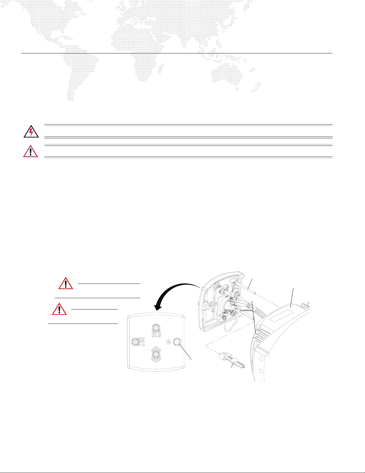
Step 3. At backcap, loosen captive knob and slide backcap out of head assembly (it will remain attached by tether).
(Figure 4-1.)
Step 4. Remove lamp by pulling straight out of socket.
Step 5. Noting polarity of lamp to socket, install new lamp by pressing firmly into socket, making sure it is fully
seated.
Step 6. Align guide rods in guide holes and slide backcap into head assembly.
Step 7. Ensure that backcap is fully seated in rear chassis and re-tighten captive knob.
Step 8. Align lamp. (Refer to next procedure.)
CAUTION:
CAUTION:
Do not touch lamp or
reflector with bare fingers.
Allow lamp to cool
before servicing.
Backcap
Captive
Knob
Figure 4-1: Lamp Replacement
Guide Rods
Head Assembly
Lamp
44 VL6C+ ™ SPOT LUMINAIRE USER MANUAL
Page 53
Aligning the Lamp
The design of the VL6C+ optical system is based on an optimally flat field. A flat field is one where there is no
detectable hot spot.
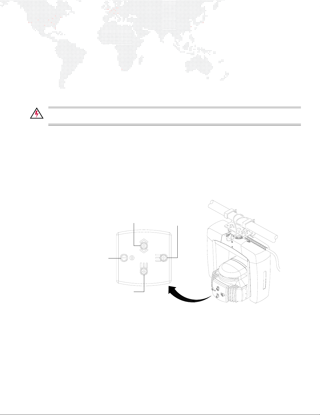
After a new lamp is installed, it will be necessary to align the lamp to optimize the beam. Knobs located at the
luminaire’s backcap allow for adjustment.
Tools:
Screwdriver, #2 Phillips
To align lamp:
WARNING: Backcap and adjustment knobs will be HOT during lamp operation. Wear gloves and/or use
tools to prevent burns.
To align lamp:
Step 1. Power up luminaire and allow to warm up for at least ten minutes.
Step 2. Set intensity to 100%.
Step 3. Position beam on a white wall at a distance of 10' to 20'.
Step 4. Using control console, open beam size iris, set zoom for mid-range, and adjust for hard edge.
Step 5. At backcap, using vertical and horizontal knobs, adjust hot spot to center of beam
(Figure 4-2.)
Step 6. Using focus knob, adjust beam for flat field.
Captive Knob for lamp access
(does not adjust beam)
Focus
Vertical
Horizontal
Figure 4-2: Lamp Alignment Controls
VL6C+ ™ SPOT LUMINAIRE USER MANUAL 45
Page 54
Replacing a Standard Gobo or Color Filter
Parts:
Standard Gobo or Color Filter, as required
Tools:
Screwdriver, #2 Phillips
WARNING: Remove power from luminaire before performing any maintenance procedures.
To remove and replace a standard gobo or color filter:
Step 1. Remove power from luminaire.
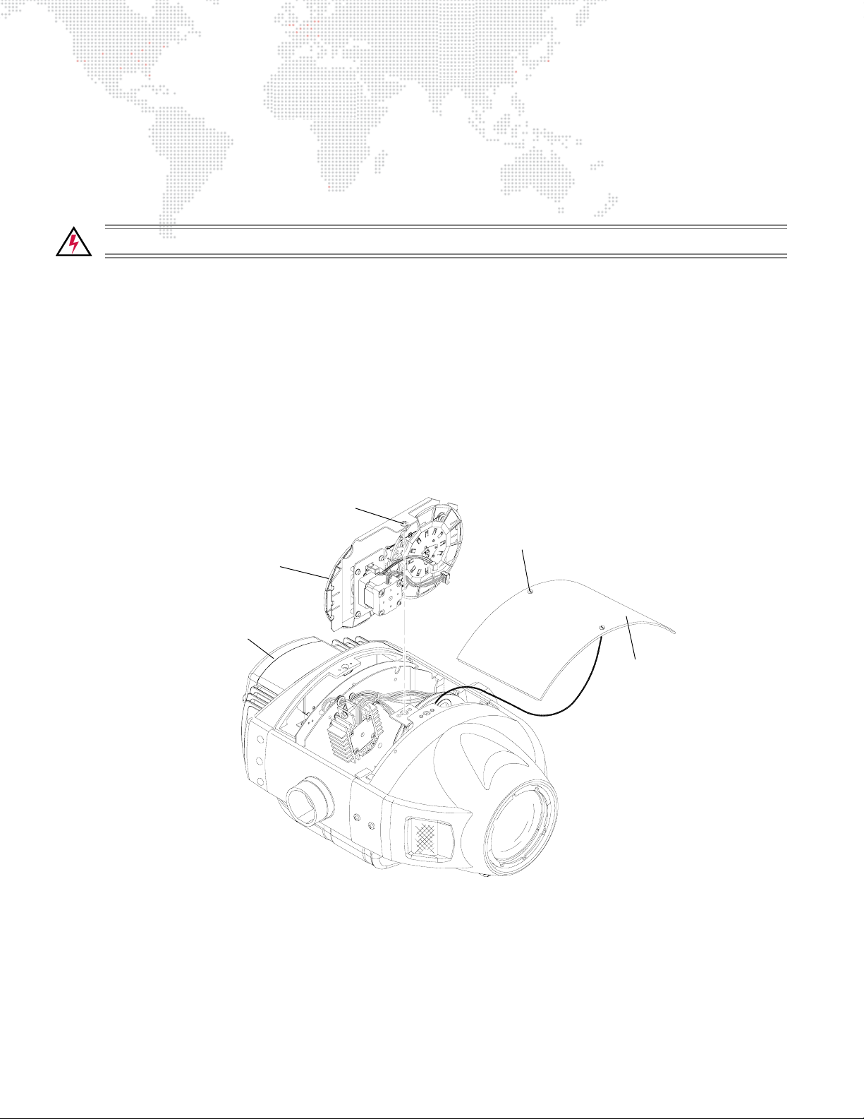
Step 2. At head assembly, turn two captive screws one-quarter turn and remove cover (it will remain attached by
tether). (Figure 4-3.)
Step 3. In some cases it is easier to slide the color/gobo bulkhead partially out of the head assembly to access
gobo and color filters. If required, do the following:
a. At Yoke Termination PCB, disconnect cables at locations J10-J17. (Cables are labeled for easy re-
connection.)
b. At color/gobo bulkhead, turn captive screw one-quarter turn to release bulkhead.
c. Remove bulkhead from head assembly.
Captive Screw
Captive Screw (2)
Color/Gobo Bulkhead
Head Assembly
Removable
Cover
Figure 4-3: Removing Color/Gobo Bulkhead
Step 4. If not removing color/gobo bulkhead, simply rotate wheel until gobo or color filter is accessible.
46 VL6C+ ™ SPOT LUMINAIRE USER MANUAL
Page 55

CAUTION: Do not touch gobo or color filters with bare fingers. Wear cotton gloves or other covering while
replacing.
Step 5. Using fingers, grasp frame of gobo or color filter and pull out of wheel hub (Figure 4-4.)
Gobo or Color Filter
Carrier Slot
Gobo or Color Wheel Hub
Figure 4-4: Replacing a Standard Gobo or Color Filter
Step 6. Noting proper orientation of carrier slot, insert new gobo or color filter into position and push fully into place.
Step 7. Re-install color/gobo bulkhead, as required, and re-connect cables to Yoke Termination PCB (Figure 4-3.)
Step 8. Re-install removable cover by positioning cover on head assembly and tightening two captive screws.
VL6C+ ™ SPOT LUMINAIRE USER MANUAL 47
Page 56
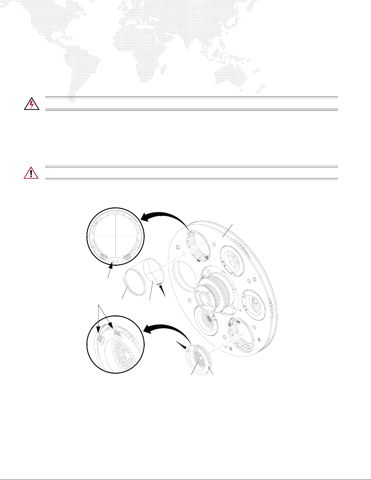
Replacing a Rotating Gobo
Parts:
Rotating Gobo, as required
Tools:
Screwdriver, #2 Phillips
WARNING: Remove power from luminaire before performing any maintenance procedures.
To remove and replace a rotating gobo:
Step 1. Remove power from luminaire.
Step 2. At head assembly, turn two captive screws one-quarter turn and remove cover (it will remain attached by
tether). (Refer back to Figure 4-3.)
Step 3. At rotating gobo wheel, spin wheel so that desired gobo is accessible.
CAUTION: Do not touch gobo with bare fingers. Wear cotton gloves or other covering while replacing.
Step 4. Remove gobo from wheel by pulling outward (Figure 4-5).
while the other gobos do not.
Flat Edge
Notches
Spring
4-Facet
Prism Gobo
Note that the 4-Facet Prism gobo has a spring,
Rotating Gobo
Wheel
Standard Rotating Gobo
Cup
Figure 4-5: Replacing a Rotating Gobo
Step 5. Install a new Prism gobo by aligning flat edge of gobo with flat space between the two notches on gobo
wheel.
CAUTION: If this is not done correctly, gobos will not index properly across multiple luminaires, and
can also fall out of the wheel.
Step 6. Install a new standard gobo by aligning the two notches in the gobo’s cup with the notches on the gobo
wheel.
Step 7. Re-install head cover.
48 VL6C+ ™ SPOT LUMINAIRE USER MANUAL
Page 57
Cleaning the Luminaire
Tools:
Clean, lint-free cloth (2)
Window cleaner
99% + Isopropyl alcohol
Vacuum cleaner with brush nozzle or compressed air
To clean the outside of the luminaire:
WARNING: Remove power from luminaire before performing any maintenance procedures.
CAUTION: Use caution when handling lenses or reflector. Avoid scratching optical surfaces.
Step 1. Remove power from luminaire.
Step 2. Using vacuum cleaner with brush nozzle or compressed air, clean dust from external components.
compressed air to clean out luminaire, DO NOT allow fans or blower to spin at high speeds, as this will
damage their bearings.
Step 3. Using window cleaner and a clean, lint-free cloth, wipe outside surface of luminaire.
DO NOT use window cleaner on lenses or reflector.
Step 4. Using 99% + Isopropyl alcohol and a clean, lint-free cloth, clean lenses and reflector.
If using
VL6C+ ™ SPOT LUMINAIRE USER MANUAL 49
Page 58

Notes
50 VL6C+ ™ SPOT LUMINAIRE USER MANUAL
Page 59

A.
TECHNICAL SPECIFICATIONS
Page 60

VL6C+ Spot Luminaire
Description
SOURCE: 700 Watt Short Arc Metal Halide Lamp
Color Temperature 5600°K
CRI 80
OUTPUT: 15,500 lumens
BALLAST. Lamp power is provided by an APS6 module in the Modular Power Distribution Rack at 90
to 264 VAC, 50/60 Hz.
LOW VOLTAGE: Luminaires are powered through a Smart Repeater or Smart Repeater Plus processing unit.*
REFLECTOR: Precision glass reflector with dichroic cold mirror coating.
OPERATING TEMP: -20° to 120°F (-29° to 49°C)
COOLING: Forced air.
CONTROL: Compatible with all PRG consoles and a wide variety of DMX-512 consoles.
POSITIONING: Can be mounted and operated in any orientation.
SPACING: Hangs on 19 in. (483 mm) centers.
WEIGHT: 29 lbs (13.2 kg)
Programmable Functions
ZOOM: Continuously variable field angle from 19° to 43°, programmable over a timed range of 2
seconds to 20 minutes.
BEAM SIZE CONTROL: In addition to the zoom optics, a mechanical iris provides continuous beam size control for
both rapid changes and smooth timed beam angle changes.
INTENSITY: Full field dimming designed for both smooth timed fades and strobe effects.
COLOR & GOBO: Two wheels, each providing 11 easily loaded positions for user-selectable color and gobo
choices.
ROTATING GOBO: Six-position rotating gobo wheel with five rotatable, indexable gobo positions and one open
position. Smooth and stepless individual gobo rotation over a range from 0.2 RPM to 80
RPM in either direction. Angular resolution is 0.3°.
EDGE & FOCUS: Variable beam focus to soften edges of gobos or spots.
PAN & TILT: Smooth, time controlled continuous motion by way of a digital servo system.
RANGE: Pan - 360°, Tilt - 270°
MAX VELOCITY: 240° per second.
ACCURACY: 0.3° resolution.
* A maximum of three (3) VL6C+ Luminaires may be powered from a Smart Repeater unit and a maximum of six (6)
VL6C+ Luminaires from a Smart Repeater Plus unit.
52 VL6C+ ™ SPOT LUMINAIRE USER MANUAL
Page 61
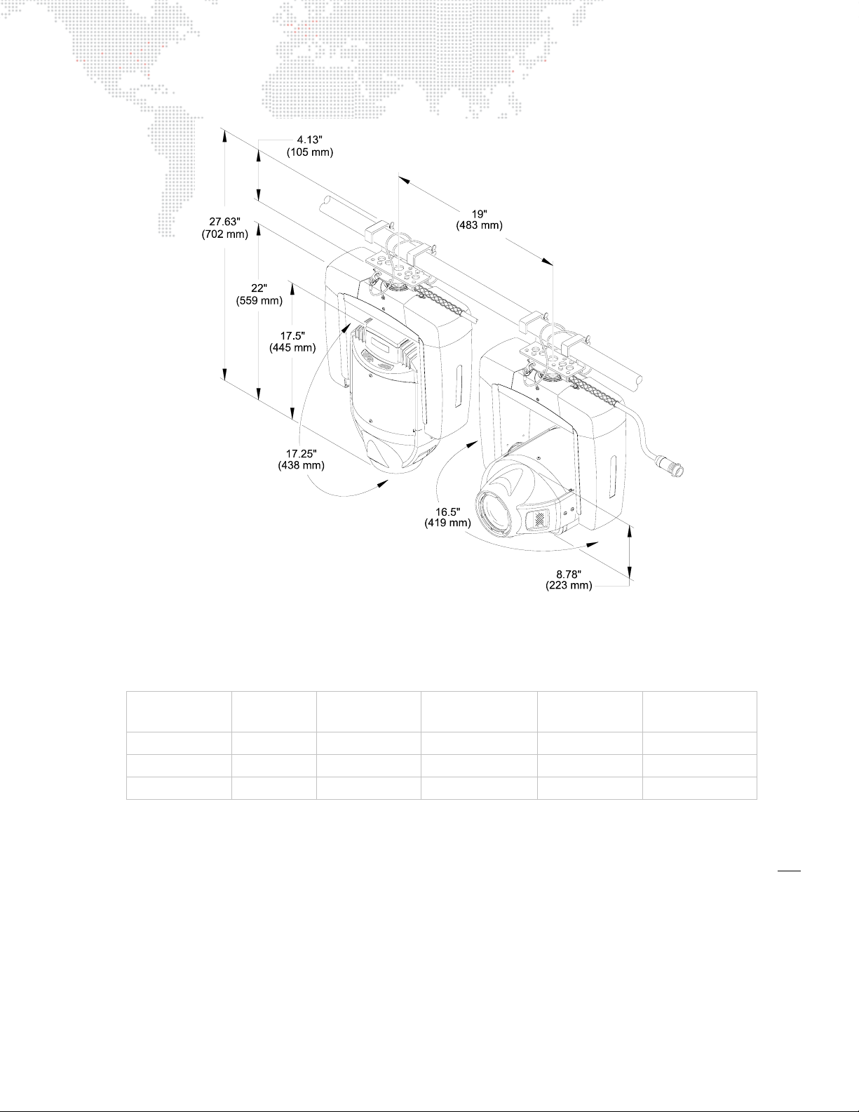
Photometric Data
VL6C+ Luminaire with 700W Short Arc Metal Halide Lamp
ZOOM LENS
POSITION
CANDELA*
(cd)
BEAM ANGLE
(degrees)
BEAM DIAMETER
1
(Tn)
FIELD ANGLE
(degrees)
FIELD DIAMETER
NFOV 297,000 15.0° .263 18.5° .326
MFOV 104,000 25.0° .443 30.5° .545
WFOV 50,000 34.5° .621 42.5° .777
1
Multiply throw distance by Tn to determine coverage.
To calculate center beam illuminance (I) at a specific distance (D):
-- if (D) is in feet, (I) is in foot candles
-- if (D) is in meters, (I) is in lux
* All data taken with seasoned light source at 20 hours of life.
VL6C+ ™ SPOT LUMINAIRE USER MANUAL 53
(Tn)
1
cd
I =
2
D
Page 62

Notes
54 VL6C+ ™ SPOT LUMINAIRE USER MANUAL
Page 63

B.
GLOSSARY
This glossary provides useful terms associated with operating VL6C+ Spot Luminaires.
Page 64

Glossary of Terms
Address
A numerical "name" given to a device on a DMX512 line indicating which of 512 possible channels it will respond to.
Align (lamp)
The process of adjusting the lamp within the reflector to obtain the desired output quality of the beam.
APS6 Module
The lamp power supply (ballast) for arc lamps found in the VL6C+ Luminaire.
APS6 Trunk Cable
Multi-conductor cable used to provide six circuits of arc lamp power to VARI
industry standard six circuit Socapex cable by using pin 19 as a shield to eliminate RF noise, which can interfere with
sound systems. (Can be used with incandescent lamps.)
Arc Lamp
A type of lamp which creates light by forming an arc of electricity. Brightness is achieved by including gasses and
metals within the envelope of the lamp which dissolve and give off a bright light. Arc lamps must be dimmed
mechanically because electrical dimming will extinguish the arc.
Attribute
An individual controllable aspect of a luminaire: pan, tilt, color, etc. Also known as "parameter."
❋LITE Series 300 luminaires. Differs from
Beam
1) The size, shape and sharpness of image of the light beam as projected on stage.
2) A function of the luminaire related to the size, shape, and sharpness of the light beam, specified by beam and edge
data, and use of gobos (patterns) as required.
C3 Dimmer
The VARI
intensity of a VL5 or VL5B wash luminaire.
Channel
A control reference which collects a device’s associated thumbwheel address(es) (device, lamp power, etc.) and maps
them to a single selectable number. Channels are assigned via the patch setup. (Also referred to as a "Control
Channel.")
Console Timing
Time value in seconds or minutes applied to an entire cue.
Dimmer
Device used to control the relative output (or intensity) of an incandescent lamp.
DMX512
Digital multiplexing; an industry standard protocol. 8-bit protocol with a maximum of 256 steps of resolution per
channel. Maximum of 512 controllable channels per DMX data stream.
❋LITE current sensing dimmer that can be installed in a Modular Rack SixPack chassis to control the
DMX512 Cable
Industry standard cable consists of two twisted pair and a shield, and 5-pin XLR style connectors. The pin out is: pin
1 = common (shield), pin 2 = data -, pin 3 = data +. The second pair (pins 4 & 5) may be used for a secondary data
link; in VARI
56 VL6C+ ™ SPOT LUMINAIRE USER MANUAL
❋LITE equipment, these pins are not used.
Page 65

DMX Power Pack
The DMX Power Pack (DPP) is a portable electronics chassis that provides lamp power and control to Series 300
luminaires.
DMX512 Universe
A group of up to 512 DMX channels. Consoles may have more than one universe, usually labeled in groups of 512.
Douse
To de-energize a luminaire lamp. (Douse is unrelated to intensity states.)
Epic Connector
A six-pin, three-phase 35 amp connector found on 8/5 wire used to provide power to a Modular Rack SixPack
chassis.
Fan-In
(Break-In) 6 male plugs to female multicore connector. In the case of Series 300 equipment, a Socapex connector.
Fan-Out
(Break-Out) A male multicore connector to 6 female plugs. In the case of Series 300 equipment, a Socapex connector.
Feeder
In the case of Series 300 equipment, 2/0 double-insulated wire, rated at 225 amps, with 4\0 Cam-Lok connectors on
either end, color coded by phase, neutral and ground.
Fixture Orientation
Based on the direction the pigtail points as it exits the fixture.
Flipped Focus
When one or more fixtures inadvertently move differently from others in the system.
Focus
The point to which the light beam is directed. Also, a function of the luminaire related to the direction of the beam as
specified by pan and/or tilt data.
Frame
A luminaire mechanism which allows framing of the light beam.
Gobo
A pattern (template) used to create backgrounds or texture when projected on to scenery or cycloramas, or to create
the illusion of natural elements such as fire, windows or tree leaves.
Hard Reset
Restarts luminaires and reloads operating system and cue data.
Home Position
Pan and Tilt values at 50%. Also called “Zero Position” or a "50/50" cue or group.
Hubbell Connector
A five-pin, three-phase connector found on 8/5 wire, used to provide power to a Modular Rack SixPack Chassis,
when used with the proper Epic to Hubbell adapter.
Indexing
A function of a rotating gobo mechanism.
VL6C+ ™ SPOT LUMINAIRE USER MANUAL 57
Page 66

Intensity
A value placed on the relative brightness of a lighting fixture; 100% is considered "full," and 0% is considered "out."
Lamp
Light source consisting of filament or electrodes, base, and envelope or "bulb."
Lamp Cable
VARI
❋LITE cable that extends the fixture pigtail to a Smart Repeater unit.
Luminaire Calibration
The process of a luminaire finding its end stops for all parameters.
Mini-Stepping
Allows for smoother movement of color and gobo wheels in a VL6 spot luminaire.
Mode
Software contained within the Smart Repeater unit allowing for different control options for luminaires.
Modular (Mod) Rack
A power distribution and storage rack for SixPack chassis. The Mod Rack is fitted for 200A Cam-Lok input, with six
Epic connectors for individual outputs for up to four rack-mounted chassis and up to two auxiliary chassis. The Mod
Rack also has a space for one SPC-36 controller for control of the modules within the chassis.
Output Port
One of the six plugs on the long side of a Smart Repeater unit, with port one being closest to the Socapex connector.
Palette
Term for groups of groups; i.e. all the color groups would be considered the Color Palette, all the beam groups would
be the Beam Palette, etc.
Pan
The 360° movement of the luminaire around the axis of the yoke.
Parameter
An individual controllable aspect of a luminaire: pan, tilt, color, etc. Also known as "Attribute."
Part Cue
Basically a "cue within a cue." A portion of a cue with a time applied that is different than the cue time.
Patch
The act of assigning a DMX512 channel to a control channel on a console.
Pigtail
Input cable of a Series 300 luminaire.
Reply
Digital data signals transmitted from each luminaire to the console. Only one luminaire may transmit at a time, in
response to a request from the console.
Signal
Control protocol from a lighting console or interface.
58 VL6C+ ™ SPOT LUMINAIRE USER MANUAL
Page 67

SixPack Chassis
Case used for lamp power distribution. Each chassis can contain up to six modules - APS6 and/or C3 in any
combination. Each slot in the chassis corresponds to an output port on the Smart Repeater unit. The SixPack Chassis
connects to the Smart Repeater unit through an APS Cable or standard Socapex cable (if no APS6 modules are
used).
Show File
A file containing all programmed cue data.
Shutter
A mechanism which controls the douser or strobe action of luminaires capable of this function.
Smart Repeater
The Smart Repeater unit is the hub for up to six Series 300 luminaires. The Smart Repeater unit is also an interface
between the control system and the luminaires. It consolidates the three things necessary to run Series 300 luminaires
into one lamp cable: Control Signal, Lamp power and Motor/Control power.
Socapex Cable
Industry standard multicore cable is used to distribute lamp power to luminaires. It is often created using 19-pin
Socapex or Veam connectors and 12/18 cable for six 20A circuits.
Splitter (Isolator)
Device used to optically isolate and split a DMX512 signal.
Note: A DMX "two-fer" cannot be used to divide a signal.
Start
To energize a luminaire arc lamp (applies to arc-lamp luminaires only).
Tails
In the case of Series 300 equipment, 2/0 double-insulated wire, rated at 225 amps, with 4\0 Cam-Lok connectors on
one end color coded by phase, neutral and ground and bare wire on the other, or 8/5 multicore wire with a female
connector (Hubbell or Epic) on one end, and bare wire on the other.
Terminate/Termination
Termination refers to the dampening of DMX signal at the end of the transmission line. Termination is created by
placing a 100 ohm resistor between pins 2 and 3 of the DMX line. Often, there is a switch on DMX devices to do this
internally. If not, a terminator is provided in the form of an XLR connector with the proper resistor between pins 2 and
3 to be placed in the DMX Thru port on the device.
Test Software
Software resident in the Smart Repeater unit that allows for troubleshooting of a Series 300 luminaire.
Three-Phase Power
In order to manufacture electricity efficiently, it is created in what is known as three "phases". In other words, in its
creation, the sine wave of alternating current are offset by 120°. The VARI
❋LITE system runs on three-phase power,
as indicated by the five Cam-Lok connectors on the mod rack - Phase X, Phase Y, Phase Z, Neutral and Ground. Each
phase in a 200A feed can support 200A of equipment. To adequately power the same amount of equipment on a
single phase, you would need a 600A feed.
Thumbwheel Switch
Three digit switching device used to set the range of channels a particular Smart Repeater unit or other Series 300
hardware device looks at for control information. Also used to set the operating mode of a Smart Repeater unit.
VL6C+ ™ SPOT LUMINAIRE USER MANUAL 59
Page 68

Tilt
The movement of the luminaire around the axis of the tilt tube.
Time
Control of the duration of the change of the variable parameters of VARI
❋LITE automated luminaires and other
devices in a lighting system.
Timing Channel
A Timing Channel is used in lieu of cue fade rate to determine the time it will take a luminaire to move from one setting
to another. For example, a cue in which a luminaire pans from one side of stage to the other may look "steppy" if cue
fade rate is used, because of the nature of the DMX512 signal. To overcome this, a timing channel causes the Smart
Repeater unit and luminaire to calculate the move in time, effectively smoothing out the movement. To operate
properly, the new position and timing channel levels need to be sent to the Smart Repeater in a zero count, (an instant
change).
Zero Position
Pan and Tilt values at 50%. Also called "Home Position" or a "50/50" cue or group.
8-Bit DMX
The universally accepted lighting control protocol in the entertainment industry. A console uses this protocol to
control specific devices in a lighting system. A DMX512 channel packet is eight bits of absolute parameter data. 8-bit
refers to the resolution of the signal: 256 step resolution, providing channel values from 0 through 255. A DMX512
data packet is a group of 512 data channels.
16-Bit DMX
To smooth out the movement of automated luminaires, the industry has adopted 16-bit DMX. This is not a change to
the DMX512 specification, rather a change in the way luminaires and consoles treat DMX512 information. In practice,
16-bit DMX adds a DMX512 channel each to pan and tilt - pan coarse, pan fine, tilt coarse, tilt fine, instead of just pan
and tilt. The console and luminaire combine these levels and increase the resolution of pan and tilt from 256 steps to
a theoretical maximum 65,536 steps at the console level, resulting in the ability to position the luminaire more
accurately.
60 VL6C+ ™ SPOT LUMINAIRE USER MANUAL
Page 69

VL6C+™ Spot Luminaire User Manual
Version as of: November 3, 2010
PRG part number: 02.9803.0001 A
Page 70

Production Resource Group
Dallas Office
8617 Ambassador Row, Suite 120
Dallas, Texas 75247
www.prg.com
 Loading...