

Page 1

2016 DUAL OUTPUT
HARDWARE
WWW.PRG.COM
MBOX
2016 DUAL OUTPUT
MEDIA SERVER
HARDWARE MANUAL (rev. A)
®
Page 2

AutoPar®, Bad Boy®, Best Boy®, Followspot Controller™, Mbox®, Mini Node™, Nocturne®, Series 400®, ReNEW®, Super Node™, UV Bullet™,
V476®, V676®, Virtuoso®, and White Light Bullet™, are trademarks of Production Resource Group, LLC, registered in the U.S. and other countries.
Mac®, QuickTime® and FireWire® are registered trademarks of Apple Computer, Inc.
All other brand names which may be mentioned in this manual are trademarks or registered trademarks of their respective companies.
This manual is for informational use only and is subject to change without notice. Please check www.prg.com for the latest version. PRG assumes no
responsibility or liability for any claims resulting from errors or inaccuracies that may appear in this manual.
Mbox® 2016 Dual Output Hardware Manual
Version as of: September 20, 2017 rev A
PRG part number: 02.9800.0006.40
Production Resource Group
Dallas Ofce
8617 Ambassador Row, Suite 120
Dallas, Texas 75247
www.prg.com
©2017 Production Resource Group, LLC. All Rights Reserved.
Mbox® 2016 Dual Output Hardware Manual
Page 3

TABLE OF CONTENTS
Chapter 1. Hardware
Hardware Components
Mbox 2016 Dual Output Case Assembly ..................................................................................................................... 4
Dual I/O Module ........................................................................................................................................................... 5
Sonnet xMac Pro .......................................................................................................................................................... 7
Mac Pro Computer ....................................................................................................................................................... 9
Focusrite Scarlett 2i2 USB/Audio Interface ............................................................................................................... 10
Hardware Setup
Basic Setup and Connections .................................................................................................................................... 11
Connecting the Stage Output .................................................................................................................................... 12
Networking Multiple Mbox Servers ............................................................................................................................ 12
Power-Up Procedure .................................................................................................................................................. 12
Chapter 2. Dual I/O Module
Operation Overview
Function ...................................................................................................................................................................... 14
Connected Display Devices and EDID
Overview ..................................................................................................................................................................... 15
Switching Between Standard EDID or Capturing EDID ............................................................................................. 17
Possible Issues with EDID and the I/O Module .......................................................................................................... 19
Frequency Selection .................................................................................................................................................. 21
SDI Output
Overview ..................................................................................................................................................................... 21
Conguration .............................................................................................................................................................. 21
Genlock (Generator Lock)
Overview ..................................................................................................................................................................... 23
Genlock and the Dual I/O Module .............................................................................................................................. 23
DMX and Ethernet
Overview ..................................................................................................................................................................... 25
DMX ............................................................................................................................................................................ 25
Ethernet ...................................................................................................................................................................... 26
Chapter 3. Capture card
Operation Overview
Function ...................................................................................................................................................................... 28
Input ........................................................................................................................................................................... 28
Output ........................................................................................................................................................................ 29
Chapter 4. USB/Audio Interface
Operation Overview
Function ...................................................................................................................................................................... 32
Input ........................................................................................................................................................................... 32
Output ........................................................................................................................................................................ 33
MBOX® 2016 DUAL OUTPUT HARDWARE MANUAL
iii
Page 4

Appendix A. Maintenance
Routine Maintenance
Cleaning or Replacing the Air Filter ............................................................................................................................ 36
Removing the Computer ............................................................................................................................................ 37
Removing the PCIe Card Cage .................................................................................................................................. 38
PCIe cards
Overview ..................................................................................................................................................................... 39
Replacing PCIe Cards ................................................................................................................................................ 39
Additional Peripherals
Overview ..................................................................................................................................................................... 39
Appendix B. Intra-rack Connections
Intra-rack Connections
Diagrams .................................................................................................................................................................... 42
iv
MBOX® 2016 DUAL OUTPUT HARDWARE MANUAL
Page 5
REVISION HISTORY
This manual has been revised as follows:
Version Release Date Notes
revA September 20, 2017 Initial Release
MBOX® 2016 DUAL OUTPUT HARDWARE MANUAL
v
Page 6

INTRODUCTION
About This Guide
This user manual provides necessary information regarding the operation of the Mbox 2016 Dual Output hardware.
This guide is provided to explain the features in the hardware in detail. This manual is written to cover the use of
latest Mbox rental hardware. Mbox software operation is covered in a separate manual.
Important Note About Control
The Mbox 2016 Dual Output hardware is designed to work with either the Mbox Director software or moving-light
consoles. There is a new version of the Mbox Director software (v4) required to control the Mbox v4 software. Mbox
v4 will work with any moving-light console that can have a compatible prole, including: PRG V676®, V476®, and
V276 consoles, MA Lighting grandMA1 and 2 consoles, High End Systems Hog® 4 series consoles, Jands Vista,
Compulite Vector, ETC EOS and Ion consoles, and Martin M-Series consoles.
Additional Documentation
For more information about DMX512 and sACN protocols, refer to the following documents available from the
American National Standards Institute (ANSI) at www.ansi.org:
+ ANSI E1.11 - 2008 (R2013): Entertainment Technology - USITT DMX512-A, Asynchronous Serial Digital Data
Transmission Standard for Controlling Lighting Equipment and Accessories
+ ANSI E1.31 - 2009: Entertainment Technology - Lightweight streaming protocol for transport of DMX512 using
ACN
The above documents are also available in electronic format free for PLASA members at www.plasa.org
For more information about Art-Net, refer to the following document available from Artistic Licence Engineering at
www.artisticlicence.com:
+ Specication for the Art-Net Ethernet Protocol
Customer Service
For technical assistance, contact the nearest PRG ofce. Contact information for all PRG ofces can be found on
our website at: www.prg.com
For Mbox support, please contact: [email protected]
For additional resources and documentation, please visit our website at: www.prg.com
MBOX® 2016 DUAL OUTPUT HARDWARE MANUAL
1
Page 7

Notes
2
MBOX® 2016 DUAL OUTPUT HARDWARE MANUAL
Page 8

1.
1.
HARDWARE
This chapter provides an overview of the Mbox 2016 Dual Output hardware and its setup
+ HARDWARE COMPONENTS
+ HARDWARE SETUP
Page 9

HARDWARE COMPONENTS
RIGH TLEFT
BALANCE D
AUDIO OUT
LINE INST LINE INST OFF ON
DIRECT
MONITOR
48V
GAIN
0
10
GAIN
0
10
MONITOR
0
10
1 2
scarlett 2i2
2 3 41
VID EO IN PUT
STAG E B LA C K OUT
PREV IE W 1
TM
DMX
ETHE R NE T
INPUT 2
INPUT 1
RDM Tx
RDM Rx
DMX Rx
PORT 1
PORT 2
POWE R
B
A
Tx
Rx
COMPU TE R
LINK
EDID C AP T UR E
OUTPU T 1
SDI 1
A
B
GENL OC K 1
OUT
IN
PRE VIE W DIM ACTIV E USB
DVI 1
VGA 1
EDID C AP T UR ESTAG E B LA C K OUT PRE VIE W DIM ACTIV E USB
SDI 2
GENL OC K 2
DVI 2 PREV IE W 2
VGA 2
A
B
IN
OUT
OUTPU T 2
Dual I/O Module
HDMI
ENE T A ENE T B
DVI 1 DVI 2
100-240V. 50-60Hz
1
2
3
234 1
LEFTRIGHT
LINE OUT P UT S
USB
LEFTR IG HT
FAULT
SITE WIRING
SENSIBILITY
OUTPUT: 120V 50/60 Hz
INPUT
RESET
PUSH TO
PROTECTOR
OVERLOAD
USB PORT
Mbox 2016 Dual Output Case Assembly
The following illustrations show the main case components for the Mbox 2016 Dual Output hardware:
UPS Power Unit
Dual I/O Module
1
FRONT VIEW REAR VIEW
Focusrite Scarlett 2i2
USB/Audio Interface
Computer
4
Mac Pro
3
Sonnet xMac Pro
2
Ethernet, USB, and
DVI Connections
Mac Pro
Computer
3
UPS Power Unit
Ethernet, RAID, and
Capture Cards
1 - Refer to “Dual I/O Module” on page 5.
2 - Refer to “Sonnet xMac Pro” on page 7.
3 - Refer to “Mac Pro Computer” on page 9.
4 - Refer to “Focusrite Scarlett 2i2 USB/Audio Interface” on page 10.
4
MBOX® 2016 DUAL OUTPUT HARDWARE MANUAL
Page 10

Dual I/O Module
Function
The function of the Dual I/O module is to provide video conversion, nal dimming of the video signal, and to send EDID
information to the Mac computer. The module also handles DMX512, sACN, and Art-Net input for the computer.
The module functions as a “dual” unit since it provides two independent output sections. These sections are noted in
the drawing below as “Server Output 1” and “Server Output 2.” While the two sections use identical hardware, because
they are independent, they must be congured separately.
Note: This section is intended to be an overview of the Dual I/O module components. For more information regarding
module operation, refer to “Chapter 2: Dual I/O Module”.
Front Panel Components
Stage
Blackout
Switch
Preview
Dim Switch
EDID
Capture
Switch
Active LED
Indicator
USB LED
Indicator
Server Output 1
Server Output 2
ST A GE B L AC K OU T
OUT P UT 1
VG A 1
ST A GE B L AC K OU T PR E VI EW D IM
VG A 2
VGA
Stage
Output
DVI 1
OUT P UT 2
DVI 2 PR E VI EW 2
DVI
Stage
Output
PR E VI EW D IM
ED ID CA PT UR E
A
PR E VI EW 1
ED ID CA PT UR E
A
DVI
Preview
Output
HD-SDI
Preview
Output
SD I 1
SD I 2
AC TI VE US B
B
AC TI VE
B
IN
OUT
GE NL OC K 1
US B
IN
OUT
GE NL OC K 2
Genlock
Input/Output*
HD-SDI
Stage
Output
DMX R x
RDM R x
RDM Tx
DMX
INP UT 1
DMX Inputs
TM
Dual I/O Module
E THE R NE T
INP UT 2
PO R T 1
Ethernet (Art-Net/
sACN) Connectors
PO R T 2
PO WE R
CO MP UTE R
LINK
Tx
Rx
A
B
+ Stage Outputs - The module provides three (3) stage outputs: VGA, DVI, and HD-SDI. The intensity level of these
stage outputs can be mastered by the Mbox software’s Global Master Intensity parameter. The stage outputs are
automatically blacked out when the Mbox application is not running or is in window mode.
+ Stage Blackout Switch - When this switch is set to “Yes,” the stage outputs will be blacked out.
+ Preview Dim Switch - When this switch is set to “Yes,” the preview outputs will have the same dimming state as the
stage outputs.
+ EDID Spoof/Capture Switch - The right-hand switch controls the EDID spoof/capture functions of the I/O module.
This switch is used when switching between the built-in EDID sets and when capturing EDID from any EDID
(Extended Display Identication Data) compliant device.
+ Preview Outputs - The module provides two (2) preview outputs: DVI and HD-SDI. The preview outputs are for local
monitors and are not affected by the hardware dimmer in the Dual I/O module (controlled by the intensity channel on
the Master xture).
+ EDID Capture - Genlock In/Out - The Genlock connectors are used with the Generator Lock function, which can
be used to sync the graphics card in the computer to a reference signal. Genlock Input and Output connectors are
provided on both output sections. Normally, only the top pair of genlock connectors are active.
Note: The Genlock Out connector is not a passthrough. The output should only be used if an Mbox server is the source
for the reference signal. Do not use the Genlock Out connector to daisy-chain genlock between servers!
MBOX® 2016 DUAL OUTPUT HARDWARE MANUAL
5
Page 11
+ DMX Input - The DMX512 XLR connectors are used to receive DMX512 data from an external console or other
controller. Electronics in the I/O Module automatically convert DMX input on these connectors to Art-Net that is then
broadcast via the Ethernet connectors on the I/O Module. The left-hand DMX512 input will be converted to Art-Net
universe 0, while the right-hand DMX512 input will be converted to Art-Net universe 1.
Note: DMX512 cables only carry one universe of data, and the minimum number of universes that the Mbox v4 Designer
software requires is two. When using more than twelve layers or more than four Output Masters, the software requires
three or more universes for control. In such cases, Art-Net or sACN should be used for control, rather than DMX.
+ Ethernet - The I/O Module has a built in 10/100 Ethernet switch that places all four of its Ethernet connections onto
the same physical network. Due to the speed of this switch, the two Ethernet connectors on the front panel should
normally be used only for sACN or Art-Net input from a control console. The two Ethernet connectors can be used
to daisy-chain Art-Net or sACN signal to more than one Mbox server. With one connector acting as the “in” and the
other acting as the “through.”
Note: If the I/O Module is receiving DMX512 data, then Ethernet cables would not normally be connected between
either of the Ethernet connectors on the front of the I/O Module and another Mbox server.
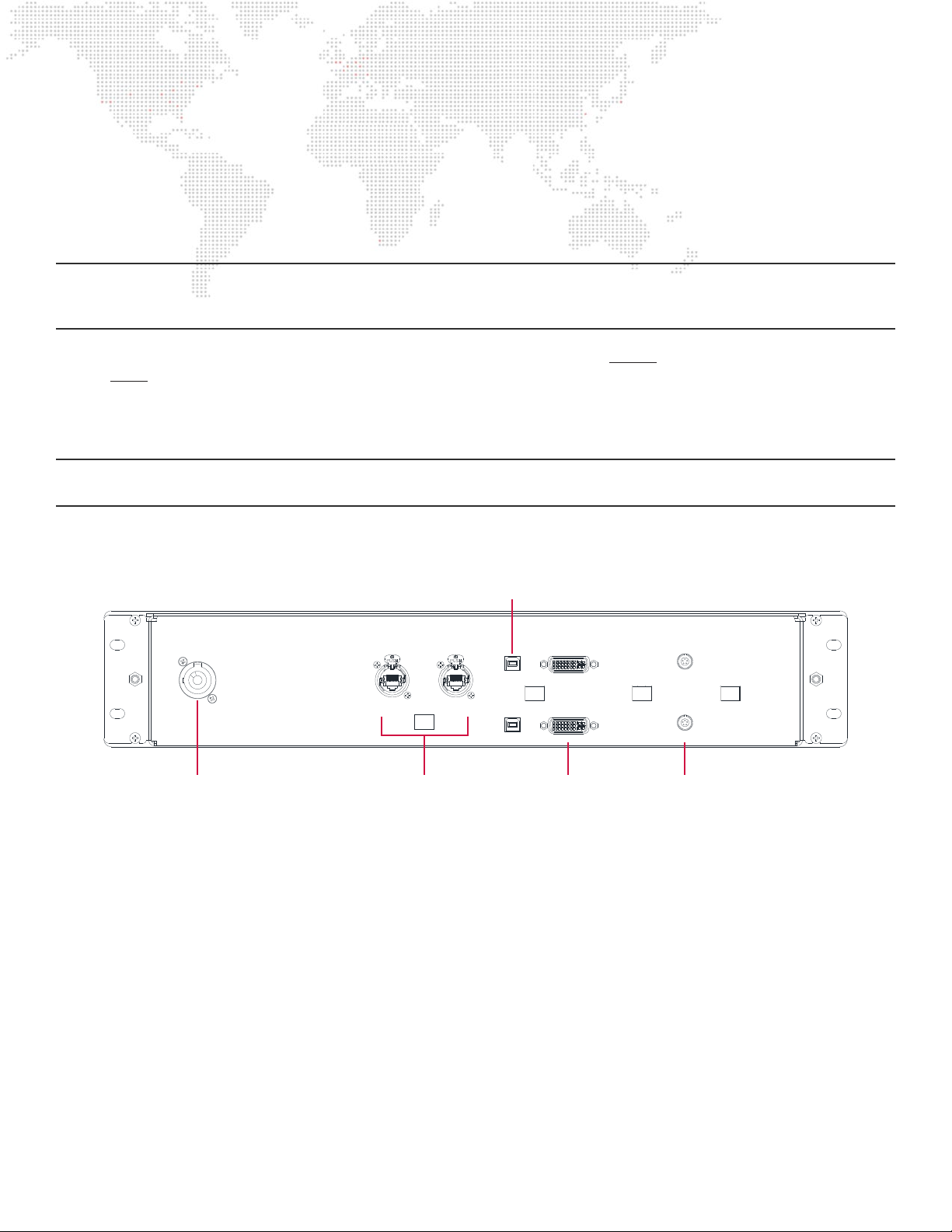
Rear Panel Components
USB
Connectors
(1 & 2)
A C IN
100 -240 VA C
50 / 60 Hz
1A MA X
E THE R NE T A E THE R NE T B
AC Input Connector DVI Inputs
Ethernet (Art-Net/sACN)
Connectors (A & B)
US B 1
US B 2
DV I IN 1
DV I IN 2
(1 & 2)
VID E O S Y NC 1
VID E O S Y NC 2
Video Sync
Connectors
(1 & 2)
+ AC Input - The I/O Module uses a Neutrik PowerCON connector for power.
+ Ethernet - These connectors allow Art-Net/sACN data to pass from either of the Ethernet connectors on the front
of the I/O Module to the Mac Pro computer. Normally, only The “Ethernet A” connector will have an Ethernet cable
connected to it.
+ USB - These connectors allow for control of the I/O Module by the Mac Pro computer. Both connectors must have
a USB cable connected to them.
+ DVI Input - These connectors receive DVI signals from the Mac Pro computer. Both connectors must have a DVI
cable connected to them.
+ Video Sync - These connectors allow video sync signals to pass from the I/O Module to the Genlock Controller on
the rear of the Sonnet xMac unit. Normally, only the top connector will have a sync cable connected to it.
6
MBOX® 2016 DUAL OUTPUT HARDWARE MANUAL
Page 12

Sonnet xMac Pro
Function
The Mbox 2016 Dual Output hardware includes a Sonnet xMac Pro unit. This unit’s primary function is to hold the Mac
Pro computer and three PCIe cards. The xMac Pro provides a Thunderbolt to PCIe bridge between the Mac Pro and the
PCIe cards. The xMac Pro unit also houses the four video input connectors.
Front Panel Components
Video Inputs
V IDE O I NP UT
2 3 41
Power Button
Filter Panel
Power
Indicator
USB
Connector
Mac Pro
Computer
+ Power Switch - This switch is used to power up the Mac Pro computer, which in turn powers up the PCIe card cage.
+ Power Indicator - This blue LED illuminates to indicate that the PCIe card cage has powered up. This is also a good
indication that the Mac Pro computer is turned on.
+ Mac Pro Computer - The bottom of the Mac Pro computer extends through the front of the xMac’s front panel. This
allows for air to be drawn through the computer for cooling purposes.
+ Filter Panel - Foam behind the front panel acts as a lter for the air that cools the PCIe cards. The entire front panel
can be removed to access the lter for cleaning purposes.
+ Video Inputs - These four connectors allow HD-SDI video to input into the Blackmagic Decklink Quad capture card
in the xMac unit’s PCIe card cage.
+ USB - This connector provides front panel access to the Mac Pro’s USB, so as to allow the connection of a keyboard
or other USB peripherals.
WARNING! Do not block the front of the Mbox rack! This will prevent proper airow through the Mac Pro computer and
Sonnet xMac unit.
MBOX® 2016 DUAL OUTPUT HARDWARE MANUAL
7
Page 13

Rear Panel Components
Genlock
Controller
Power
(Power Relay)
DV I 1 DV I 2
Power
Relay
Thunderbolt
234 1
100-240V. 50-60Hz
(Computer)
1
2
3
USBPower
HDMI
HDMI
E NE T A ENE T B
Ethernet DVI
Output
eS ATAVideo Input
Auxiliary
Ethernet
Power
(PCIe card
cage)
+ AC Power Input - There are three IEC input connectors on the rear of the xMac unit. The left-hand connector
receives power from the UPS. The center connector (on the Power Relay) also receives power from the UPS. The
right-hand connector receives switched power from the Power Relay.
+ Power Relay - This item provides switch AC power to the PCIe card cage and is controlled by a FireWire connection
to the Mac Pro computer.
+ Genlock Controller - This item receives the video sync signal from the I/O Module and converts it into the signal
used to sync the graphics card in the Mac Pro. The Genlock Controller has two cable connections: the visible LEMO
connector receives signal from the IO Module, and the 3.5mm TR connector on the opposite side of the unit sends
signal to the computer.
+ USB - These three connectors provide USB signal to the I/O Module (two USB cables) and also to the Focusrite
USB/Audio Interface (one cable). The audio interface can be disconnected if audio output/SMPTE input is not being
used, and other USB peripherals may be connected (e.g. storage devices).
+ DVI Output - These connectors provide DVI signals to the IO Module. Normally, both connectors will have a DVI
cable connected to them.
+ Ethernet - These connectors provide gigabit Ethernet interfaces from the Mac Pro. Normally, only the connector
labeled “Enet A” will have a cable connected to it. This cable connects to the “Ethernet A” connector on the rear of
the IO Module.
+ HDMI - This connector is not used and should not have anything plugged into it.
+ Auxiliary Ethernet - This NIC (Network Interface Card) provides two additional gigabit Ethernet interfaces from the
Mac Pro by way of the Thunderbolt to PCIe bridge.
+ e SATA - Normally these connectors are not used. They can be used to connect external storage devices.
+ Video Input - The four video cables from the xMac unit’s front panel connect to the input connectors on the capture
card.
+ Thunderbolt - These connectors provide for Thunderbolt connection between the Mac Pro computer and the PCIe
card cage. There must be a Thunderbolt cable connecting the Mac Pro to the card cage, connected to one of these
connectors. The other connector can be used as a pass-through to connect other Thunderbolt peripherals to the
computer.
8
MBOX® 2016 DUAL OUTPUT HARDWARE MANUAL
Page 14
Mac Pro Computer
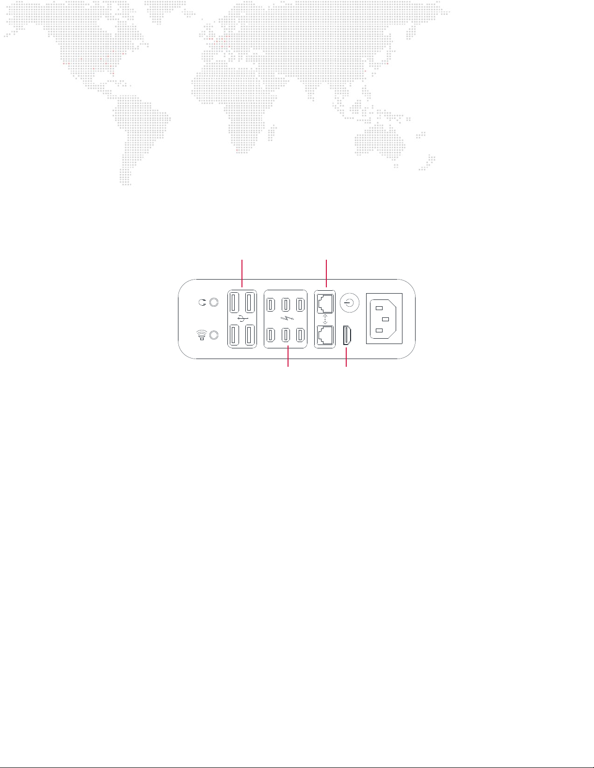
The Mbox 2016 Dual Output Server hardware includes an Apple Mac Pro computer. The Mac Pro computer runs the
Mbox software and provides input and output of various control, video, and audio signals. The computer itself has
standard computer connections for signals such as Thunderbolt, USB, and Ethernet. These connectors have cables that
send/receive signals to/from the appropriate items elsewhere in the Mbox rack
+ Hard Drive - The Mac Pro computer contains one 256GB solid-state hard drive which is used to boot the system. All
media les - including the standard media library and any custom les - are stored on a 2TB solid-state RAID housed
on a PCIe card in the PCIe card cage.
+ Graphics Card - The Mac Pro computer contains a modied graphics card, which allows the computer’s video
output to be locked to genlock reference sync.
Ethernet (2)
B
HDMI
A
Mac Pro Connections
(located inside xMac unit)
USB (4)
1 2
3 4
TB #
1 3 5
2 4 6
Thunderbolt connectors
1, 2, 5, & 6 are used for
DVI output, Thunderbolt,
and the Power Relay
HDMI
+ Ethernet - Two Ethernet cables connect between the Mac Pro and the xMac unit’s rear panel.
+ USB - The Mac Pro has four USB connections, three to the xMac unit’s rear panel, and one to the front panel.
+ Thunderbolt - The Mac Pro has one Thunderbolt connection to the xMac unit’s rear panel.
+ DVI - Two Thunderbolt to DVI adapter cables provide video to the DVI output connectors on the rear of the xMac
unit.
+ FireWire - One Thunderbolt to FireWire adapter provides control signal to the Power Relay in the xMac unit.
+ HDMI - The Mac Pro has one HDMI connection to the rear of the xMac unit.
+ Video Sync - A custom cable assembly connects between the Mac Pro and the Genlock Controller in the xMac unit.
MBOX® 2016 DUAL OUTPUT HARDWARE MANUAL
9
Page 15

Focusrite Scarlett 2i2 USB/Audio Interface
TOP VIEW
L R
RED
BLACK
LEFT RIGHT
BLACK BOOT
RED BOOT
LE FTRIG HT
LIN E OUT P UTS
USB
BACK VIEW
SECTION
"A-A"
AA
The Mbox 2016 Dual Output Server uses a USB/Audio interface for audio output (i.e. audio playback from the Mbox
software) and for SMPTE (LTC) timecode input. The audio interface connects to the Mac Pro computer via USB
and provides 3-pin XLR connectors on the front of the xMac unit for input and output. The various switches and
potentiometers on the audio interface has must be set correctly for it to work with the Mbox software.
Front Panel Components
1 2
0
10
GAIN
LINE INST LINE INST OFF ON
scarlett 2i2
Audio Input
XLR (1 & 2)
Input Gain Headphones
0
GAIN
48v
10
48V
DIRECT
MONITOR
Direct
Monitor
MonitorLine/Inst
MONITOR
USB
LED
R IGH TLE F T
0
10
BAL ANC E D
AUDIO O UT
Audio Output
XLRs (L & R)
+ Inputs - Either Input 1 (Left) or Input 2 (Right) may be used for timecode input, but not both. Input can be balanced
or unbalanced.
+ Outputs - One or both outputs can be used for Mono or Stereo audio output.
+ Input Gain - Used to adjust audio input gain.
+ Line/Inst - Selects between Instrument and Line level inputs.
+ 48v Phantom Power - Turns on phantom power - MUST be turned OFF.
+ Direct Monitor - Allows input to be routed directly to the outputs.
+ Monitor - Used to adjust audio output level.
+ USB Indicator LED - Illuminates when the interface has a USB connection to the Mac Pro.
+ Headphones - Not used in normal operation.
Note: Refer to “Chapter 4: USB/Audio Interface” for information on the correct default settings for the audio interface’s
switches and potentiometers.
Rear Panel Components
LIN E OU TP UT S
LE FTR IGH T
Audio Output
1/4” (R & L)
USB
USB
+ Output - Two unbalanced 1/4” TR connectors provide audio output. A cable assembly provides for signal
connection to the audio output XLR’s on the front panel.
+ USB - Used to connect USB between the audio interface and the rear of the xMac unit.
10
MBOX® 2016 DUAL OUTPUT HARDWARE MANUAL
Page 16

HARDWARE SETUP
1
2
3
SDI 2SDI 3SDI 4 SDI 1
HDMI
ENET A ENET B
DVI 1 DVI 2
100-240V. 50-60Hz
234 1
RESET
LEFTRIGHT
LINE OU TP UT S
USB
LEFT
RIGHT
VIDEO S Y NC 2
FAULT
SITE WIRING
SENSIBILITY
OUTP 0V 50/60 Hz
INPUT
PUSH TO
PROTECTOR
USB PORT
USB 2
DVI IN 2
VIDEO S Y NC 1
ETHER N ET A
50 / 60 Hz
1A MAX
100 -240 VA C
AC IN
USB 1
ETHER N ET B
DVI IN 1
Basic Setup and Connections
To interconnect the case components:
Step 1. Remove front and back covers from case.
Step 2. Remove keyboard and trackball from case.
Remove covers
➊
Remove keyboard and trackball
➋
Step 3. At rear of case, verify that DVI (2), USB (3), Ethernet (1), Video In (4), Thunderbolt (1), Video Sync (1), and IEC
power cables (3) are connected to the Sonnet xMac unit’s rear panel.
Verify rear connections
➌
Step 4. At front of Dual I/O Module, connect local monitor data cables to DVI Preview connectors.
Step 5. Connect local monitor power cables to UPS or to local AC power service.
Step 6. Connect UPS power cable to local AC power service.
Step 7. Connect video output Stage connectors according to the following sections.
Connect monitors and power
➍
MBOX® 2016 DUAL OUTPUT HARDWARE MANUAL
11
Page 17

Connecting the Stage Output
The Stage output should be connected to one or more of the outputs connectors on the front of Dual I/O Module. Which
connector will vary depending on the type of display device(s) being used. (Refer to “Dual I/O Module” on page 5.)
Guidelines:
+ Adapters or converters may be required to convert these outputs to specic needs.
+ All DVI connectors on the Dual I/O Module are DVI-D (digital only). There is no analog signal present on these
connectors, therefore, a DVI-to-VGA adapter will not work.
Networking Multiple Mbox Servers
The Sonnet xMac unit has two Ethernet connectors - labeled “Enet A” and “Enet B” - on its rear panel. These connect
to the Mac Pro computer’s two built-in Ethernet interfaces. Enet A has a cable that connects it to the rear of the I/O
Module. Because of the Ethernet switch in the I/O Module, the Enet A connection is part of a physical network with the
two Ethernet connectors on the front of the Dual I/O module. As noted previously, this network should be dedicated to
Art-Net or sACN reception and should NOT be used for any other purpose.
To network multiple Mbox servers together for the purpose of content distribution or remote monitoring, use either the
Enet B connector located on the rear of the xMac unit, or use one of the two auxiliary Ethernet connections on the NIC
in the PCIe card cage. The Mac Pro computer’s two built-in Ethernet interfaces have preset addressing for the ArtNet/sACN control and general networking. Changing these settings may lead to a loss of functionality, though some
exceptions may apply in certain cases (e.g. pixel mapping, refer to the Mbox Remote User manual for more information).
The two auxiliary Ethernet interfaces can be congured on an as-needed basis for additional networking functionality
(scenic tracking, content management, etc.)
Power-Up Procedure
Use the following procedure to power up the Mbox 2016 Dual Output server.
Step 1. Ensure UPS is powered up.
Step 2. At the front of the xMac unit, press the power button and allow the computer to boot. The blue power
indicator LED should illuminate.
Step 3. Press the power button of any connected preview monitors.
Step 4. Allow the Mbox software to launch. The software should start automatically, but if it does not, click on the
Mbox Launcher icon in the dock. Alternately, locate the application in the Mbox folder and double-click on
it.
Step 5. Mbox is now ready for operation.
IMPORTANT! On Mbox 2016 Dual Output servers, the Mbox application is set to go into fullscreen mode immediately
when the application launches! Because of this, the monitors may display a black image if no control data is present or
if control data is not causing any content to be visible.
12
MBOX® 2016 DUAL OUTPUT HARDWARE MANUAL
Page 18

1.
2.
DUAL I/O MODULE
This chapter provides additional information on the setup and use of the Dual I/O Module
+ OPERATION OVERVIEW
+ CONNECTED DISPLAY DEVICES AND EDID
+ SDI OUTPUT
+ GENLOCK
+ DMX AND ETHERNET
Page 19

OPERATION OVERVIEW
Function
Note: For an overview of Dual I/O Module components, refer back to “Dual I/O Module” on page 5.
The Dual I/O Module handles video conversion and dimming of the video outputs, while also providing genlock and
EDID management to the Mac Pro computer. The module also handles DMX512 conversion to Art-Net and Art-Net/
sACN transmission to the computer.
The I/O Module allows the video signal to be easily recongured to work with many display devices without the need
for an external scan converter. The module receives two DVI outputs from the computer and uses these two signals
to provide two separate output sections with DVI and HD-SDI preview, and DVI, VGA, and HD-SDI stage outputs. The
two output sections are functionally identical, but are independent so that each can be congured for its own output
requirements.
During operation, the I/O Module can dim the stage outputs to full black so that “inappropriate” content - such as the
Mac desktop or Mbox Designer application windows - will not be displayed on the stage outputs (e.g., when in window
mode).
Notes:
+ The I/O Module’s format conversion is purely a change from one signal type to another. During video conversion
there is no change to resolution, scaling, or position. The I/O Module will always output the same resolution and
frequency that the computer is outputting; provided that resolution and frequency are compatible with the output
signal type (see below).
+ The module can blackout or partially dim the video output signals to levels below full brightness. This can be done
from the control console (or Mbox Director), from the Mac computer, or by using the Stage Blackout and/or Preview
Dim switches on the front of the I/O Module.
+ The I/O Module’s DVI inputs are single-link, meaning that the maximum resolution of the I/O Module’s inputs and
outputs is 1920 x 1200.
+ The DVI outputs on the I/O Module are DVI-D (digital) only and do not have any analog signal.
+ There are only a few possible resolution and frequency combinations that are compatible with conversion to HD-SDI,
so depending on the computer’s output resolution/frequency the module may not be able to output a signal.
+ The I/O Module’s HD-SDI outputs are 1.5G. Only the following formats are supported for output:
- SMPTE 259M: NTSC 480i @ 59.94Hz, PAL 576i @ 50Hz
- SMPTE 292M: 720p @ 59.94/60Hz, 1080i @ 50/59.94/60Hz, 1080p @ 24/25/29.97/30Hz
Note: The I/O Module’s HD-SDI does not support output of 720p @ 50Hz.
Server Output 1
Server Output 2
ST A GE B L AC K OU T
VG A 1
ST A GE B L AC K OU T PR E VI EW D IM
VG A 2
PR E VI EW D IM
OUT P UT 1
DVI 1
OUT P UT 2
DVI 2 PR E VI EW 2
ED ID CA PT UR E
A
PR E VI EW 1
ED ID CA PT UR E
A
SD I 1
SD I 2
B
B
AC TI VE US B
IN
OUT
GE NL OC K 1
AC TI VE
IN
OUT
GE NL OC K 2
TM
PO WE R
Dual I/O Module
DMX R x
RDM R x
RDM Tx
INP UT 1
DMX
INP UT 2
US B
E THE R NE T
PO R T 1
PO R T 2
CO MP UTE R
LINK
Tx
Rx
A
B
14
MBOX® 2016 DUAL OUTPUT HARDWARE MANUAL
Page 20
CONNECTED DISPLAY DEVICES AND EDID
Overview
Without special hardware or software, a computer can only output video resolutions and frequencies that are supported
by the connected display equipment. Display devices communicate their possible input formats via EDID (Extended
Display Identication Data). The EDID data provides information on preferred formats and available alternate formats.
In order to provide some of the specialized outputs - for example, the various SDI signals - from the Dual I/O Module,
the computer must be told that it can output specic frequencies or resolutions. For this reason, the I/O Module
incorporates EDID management for both video outputs of the Mac Pro computer. The I/O Module always tells the
computer what frequencies and resolutions are possible; EDID from connected devices is never passed through directly
to the computer unless “captured” by the I/O Module (as will be covered later in this chapter).
IMPORTANT! In order to output SDI, the I/O Module must be using one of its built-in EDID sets, and cannot be using
captured EDID.
The Mbox v4 software reads the current resolution and frequency of all connected displays, as this information is
provided by the OS. When Mbox v4 goes into Fullscreen mode it will only use the resolution and frequency that the
display is currently set to. Older versions of the Mbox application attempted to change the resolution and frequency of
outputs when entering Fullscreen mode. At times this could lead to confusing situations where the desired resolution or
frequency were not applied, or where the display device could not display a picture based on the received format.
To eliminate these issues, Mbox v4 will not change the display into another format when going into Fullscreen mode.
The resolution and frequency of a display must be pre-set in the System Preferences > Displays preference pane
before entering Fullscreen mode. When a display’s format is changed on the Displays pref pane, that new format will
update automatically in the display assignment menu for outputs in the Mbox application. (Refer to “Outputs Tab: Output
Conguration” on page 57 of the Mbox v4 User Manual)
When connecting the I/O Module’s video outputs to a display device, conrm that the display device’s desired resolution
and frequency appear and are selected in the Displays pref pane. If the desired resolution and frequency are not
available, an alternate EDID set must be selected or EDID data should be captured from the connected display device.
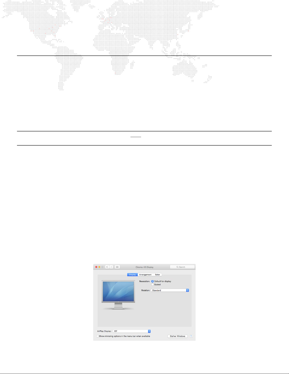
The EDID information for each of the computer’s outputs is shown in the Displays pref pane. Both outputs will show a
window similar to the illustration below. The header of each window will display the name of the EDID set (e.g. PRGMbE 60Hz) or the name of the captured EDID (e.g. Cinema HD Display as shown below).
MBOX® 2016 DUAL OUTPUT HARDWARE MANUAL
15
Page 21

When changing EDID sets or capturing EDID on the I/O Module it is necessary to force the computer to reread the EDID
by pressing the “Detect Devices” button on the Displays pref pane.
Note: In the supplied version of the Mac OS, the Detect Displays button is not visible unless the [option] key is pressed.
Once EDID has been read from the I/O Module, the Displays pref pane will display the available formats. By default,
the pref pane will select the preferred format provided by the EDID. Clicking on the “Scaled” radio button will allow the
selection of additional formats. Some formats will allow a selection of alternate refresh frequencies, but this will depend
on the EDID.
Clicking on “Scaled”
Option-clicking on “Scaled”
Note: Even after clicking on the “Scaled” radio button, all of the possible formats for the display may not be shown.
Holding down the [option] key and clicking on the radio button may reveal more possible formats.
Assuming the desired format (resolution and frequency) are available for selection on the Displays pref pane, the next
step is to actually select that format. If the desired resolution and/or frequency are not available, then the current EDID
does not support the desired format. In this case, EDID can be captured from a device that does support the desired
format.
Note: The arrangement of connected display devices is in the System Preferences > Displays pref pane not important
to the Mbox application. However, it may be helpful to arrange display devices to provide a useful working environment
when the Mbox application is in Window mode.
Default EDID Sets and EDID Capture
The Dual I/O Module can operate with one of three default EDID sets, or, if the default sets are not appropriate for the
connected display devices, then a custom EDID setting may be captured.
Default EDID Sets - Three default sets of EDID data stored within the I/O Module provide the necessary information
to work with standard computer display resolutions and frequencies, and typical SD and HD-SDI resolutions and
frequencies. These three sets include common VESA (i.e. computer) and Broadcast (i.e. SD/HD SDI) resolutions at
different frequencies.
Custom EDID Capture - At times, the default EDID sets may not provide the appropriate resolution or frequency for
the connected display devices. In these cases, EDID information from the connected displays can be captured and
presented to the computer. An EDID compliant device can be connected to the I/O Module and have its EDID data
read and captured. Captured data is stored in non-volatile memory in the I/O Module until it is replaced when EDID is
captured from a different device or when EDID is reverted back to one of the standard sets.
16
MBOX® 2016 DUAL OUTPUT HARDWARE MANUAL
Page 22

Guidelines:
+ Capturing EDID data from a specic device requires a DVI or VGA connection.
+ When capturing EDID, the I/O Module looks at the connectors in a specic order - Stage DVI rst, then Stage VGA,
and nally Preview DVI - and the rst connected device found is the only data that is captured. To reduce the
possibility of incorrect capture, it can be best if only one device is connected at the time that EDID is captured.
+ EDID must be captured for each of the I/O Module’s output sections separately.
+ It is best practice to use the same EDID for both outputs when using the I/O Module. Failure to do so may result in
a refresh frequency mismatch between the outputs, causing playback on one or both outputs to be more jerky that
otherwise.
The following chart shows the frequencies available in each of the I/O module’s three default EDID sets when a
broadcast resolution (e.g. 720p - 1280 x 720) is selected in the System Preferences > Displays pref pane.
Default EDID Sets
Desired Frequency Set 1
60Hz EDID
60Hz YES X X
59.94Hz X YES X
50Hz X X YES
30Hz YES X X
29.97Hz X YES X
25Hz X X YES
24Hz YES X X
23.98Hz X YES X
Set 2
59.94Hz EDID
Set 3
50Hz EDID
Note: Additional frequencies (e.g. 75Hz) may be available in the default EDID sets, but only when certain VESA
resolutions are selected.
Switching Between Standard EDID or Capturing EDID
The I/O Module’s current EDID set can be changed using the Stage Blackout, Preview Dim, and EDID Capture switches
on the front of the I/O Module. The position of the rst two switches (Yes or No) when the third switch is engaged, will
determine if one of the three default EDID sets is selected or if custom EDID is captured.
Server Output 1
Server Output 2
Stage
Blackout
Switch
ST A GE B L AC K OU T
VG A 1
ST A GE B L AC K OU T PR E VI EW D IM
VG A 2
Preview
Dim Switch
PR E VI EW D IM
OUT P UT 1
DVI 1
OUT P UT 2
DVI 2 PR E VI EW 2
EDID Capture
Switch and
ED ID CA PT UR E
PR E VI EW 1
ED ID CA PT UR E
LED
A
A
SD I 1
SD I 2
B
B
AC TI VE US B
IN
OUT
GE NL OC K 1
AC TI VE
IN
OUT
GE NL OC K 2
TM
PO WE R
Dual I/O Module
DMX R x
RDM R x
RDM Tx
INP UT 1
DMX
INP UT 2
US B
E THE R NE T
PO R T 1
PO R T 2
CO MP UTE R
LINK
Tx
Rx
A
B
MBOX® 2016 DUAL OUTPUT HARDWARE MANUAL
17
Page 23

To switch between the three standard EDID sets:
Step 1. Exit fullscreen mode or quit the Mbox application.
Step 2. Connect monitor to one or both preview output connectors of the I/O Module.
Step 3. Open System Preferences > Displays pref pane.
Step 4. Place Stage Blackout and Preview Dim switches in one of the following congurations (according to the
desired set):
Switch Positions
Desired EDID Set Stage Blackout Switch Preview Dim Switch
NO
NO
Set 1: 60Hz
Set 2: 59.94Hz
YES NO
NO
YES
YES NO
YES NO
YES NO
YES NO
Set 3: 50Hz
YES NOYES NO
Step 5. Flip momentary EDID Capture switch to the right and hold in position.
EDID Capture Switch
To Right
a. The indicator LED will ash rapidly for four seconds. During this time, the switch can be released and no
capturing action will take place.
b. The indicator LED will stop ashing and will illuminate. During this time, the EDID set is being changed
c. The indicator LED will start ashing slowly. The EDID set has been changed.
Step 6. On the Mac Pro computer’s System Preferences > Displays pref pane, hold down [option] and click on the
Detect Displays button. Conrm that the pref pane’s header now shows the name of the selected EDID set.
Step 7. On the Displays pref pane, select the desired resolution and frequency, clicking on the Scaled radio button to
nd additional resolutions as required.
Step 8. Relaunch the Mbox application, set it to window mode if necessary. On the Outputs tab, conrm that the
display now shows the new resolution and frequency.
It is always recommended that two monitors be connected to the I/O Module’s DVI Preview outputs and the
Displays pref pane be opened before changing EDID on the I/O Module. Furthermore, it is strongly recommended
that EDID only be changed on one output at a time so that the Gather Windows button can be used to set the
resolution and frequency of the other output should images not be visible onscreen after the EDID change.
18
MBOX® 2016 DUAL OUTPUT HARDWARE MANUAL
Page 24

To capture custom EDID:
Step 1. Exit fullscreen mode or quit the Mbox application.
Step 2. Open System Preferences > Displays pref pane.
Step 3. Connect monitor to preview output connector of the I/O Module output section that not being used for EDID
capture. Disconnect all VGA or DVI display devices from the output connectors of the output section that
will capture EDID.
Step 4. On the output section that will capture EDID, reconnect only the device to capture EDID data.
Step 5. Set both Blackout and Preview Dim switches to their “Yes” position:
Desired EDID Set Stage Blackout Switch Preview Dim Switch
YES
Capture from DVI/VGA
YES
YES NOYES NO
Step 6. Flip momentary EDID Capture switch to the right and hold in position.
EDID Capture Switch
To Right
a. The indicator LED will ash rapidly for four seconds. During this time, the switch can be released and no
capturing action will take place.
b. The indicator LED will stop ashing and will illuminate. During this time, the EDID set is being captured.
c. The indicator LED will start ashing slowly. The EDID has been captured.
Step 7. On the Mac Pro computer’s System Preferences > Displays pref pane, hold down [option] and click on the
Detect Displays button. Conrm that the pref pane header now shows the name of the device that EDID was
captured from.
Step 8. On the Displays pref pane, select the desired resolution and frequency, clicking on the Scaled radio button to
nd additional resolutions as required.
Step 9. Relaunch the Mbox application, set it to window mode if necessary. On the Outputs tab, conrm that the
display now shows the new resolution and frequency.
WARNING! If the indicator LED does not illuminate solidly (as in Step 6b) then no EDID has been captured from the
connected device. Conrm that the device is connected to one of the DVI/VGA connectors, that a working cable is
being used, and that the device does have EDID capabilities. Many DVI to Optical Fiber extenders do not transmit EDID!
Possible Issues with EDID and the I/O Module
Because the Dual I/O Module is the only source of EDID to the computer, it is possible that the formats in that EDID
result in an output resolution or frequency that a connected display device does not support. This can occur when
using devices with resolutions lower than 1920 x 1200, or devices that do not support refresh frequencies lower than
50Hz. If a connected display device does not show an image or shows an error message (e.g. “Resolution/Frequency
Not Supported”), then either a different display device is required, or the EDID needs to be changed or captured from the
connected device. If the resolution/frequency has been set to a mode where the display device cannot show an image,
neither the computer’s desktop nor the Displays pref pane will be visible. Refer to the steps below to resolve this issue.
MBOX® 2016 DUAL OUTPUT HARDWARE MANUAL
19
Page 25

To Return to a Visible Image on a Display Device
If the EDID in the I/O Module has a resolution and frequency that the connected display device does not support, it can
result in no picture on the display. Without a picture, while it is possible switch EDID sets using the switches, it is not
possible to press the Detect Displays button on the Displays pref pane because it is not visible onscreen.
The simplest solution is to nd a different display device that does support the current resolution or frequency. However,
this can be hard to determine in some cases. And alternate solution is to connect a second display to the Preview DVI
output connectors for the second output of the I/O Module to see if an image is visible there (i.e. the selected resolution/
frequency is compatible with the display).
If both of these methods are unsuccessful, it is possible to disconnect one of the DVI cables at the rear of the xMac rack
and to connect a monitor directly to that DVI connector. This will result in EDID from that monitor being presented to
the computer instead of the EDID from the I/O Module, and images being visible on the monitor. At that point, in order
to change the resolution/frequency for the I/O Module’s outputs, it will be necessary to view the Displays pref pane.
Perform the following steps to return to a supported resolution/frequency:
Step 1. Connect display devices to Preview connectors on the I/O Module.
Step 2. At the rear of the xMac unit, disconnect the DVI cable from the rst DVI output of the computer (DVI 1).
Step 3. Connect a DVI monitor directly to the DVI 1 connector at the rear of the xMac unit. Images (the Mac
desktop) should appear on the monitor, if not, make sure that the Mbox application is either in window mode
or is not running.
Step 4. Open the System Preferences > Displays pref pane and press the Gather Windows button to get the pref
panes for both outputs onto that monitor.
Step 5. Change the EDID set on the I/O Module’s second output to a different set, or capture EDID from the
connected display device. Hold down [option] and press the Detect Displays button. Then set the
resolution/frequency for the second output so that images do appear on the display device.
Step 6. Move the Displays pref pane for the second output onto the second output’s display device.
Step 7. Disconnect the monitor from the rear of the xMac unit and reconnect the DVI cable to the I/O Module. At
this point the second output should still show an image and the rst output may also show an image. If the
rst output still does not show an image, press the Gather Windows button on the Displays pref pane on the
second output and change the resolution/frequency of the rst output so that it does display an image.
If the steps above don’t result in viewable images on one or both outputs, there are still other ways to get things
working again. If another Mac computer is available, screen sharing can be used to view the screens of the Mbox
computer and to open the System Preferences > Displays pref pane to allow the display resolution/frequency to be
set to something that works.
Reverting to a Standard EDID Set
If the custom EDID data in the I/O Module is no longer needed, simply return the conguration to one of the standard
EDID sets as follows:
Step 1. Exit fullscreen mode or quit the Mbox application.
Step 2. Connect a DVI monitor to the DVI Preview connectors for both output sections of the I/O Module.
Step 3. Open the System Preferences > Displays pref pane.
Step 4. Set Stage Blackout and Preview Dim switches to new positions as required. Refer to chart on page 18.
20
MBOX® 2016 DUAL OUTPUT HARDWARE MANUAL
Page 26

Step 5. Flip momentary EDID Capture switch to the right and hold in position.
EDID Capture Switch
To Right
a. The indicator LED will ash rapidly for four seconds. During this time, the switch can be released and no
capturing action will take place.
b. The indicator LED will stop ashing and will illuminate. During this time, the EDID set is being changed
c. The indicator LED will start ashing slowly. The EDID set has been changed.
Step 6. On the Mac Pro computer’s System Preferences > Displays pref pane, hold down [option] and click on the
Detect Displays button. Conrm that the pref pane header now shows the name of the device that EDID was
captured from.
Step 7. On the Displays pref pane, select the desired resolution and frequency, clicking on the Scaled radio button to
nd additional resolutions as required.
Step 8. Perform steps 4 - 7 on the other output section of the I/O module
Frequency Selection
The Displays pref pane may or may not present one or more available frequencies depending on the selected resolution.
For example, if the Default for display radio button is pressed, typically no frequency options appear and the output
frequency will typically (but not always) be 60Hz. In most cases, the Scaled radio button must be pressed to reveal
frequency options for the display.
IMPORTANT! When using the I/O Module’s built-in EDID, in most cases a selected resolution will offer more than one
frequency with the same value. The FIRST option with the desired frequency should always be selected! Choosing any
option other than the rst may result in the output not running at exactly the desired frequency and/or no SDI output.
Additionally, when using the I/O Module’s built-in 59.94Hz EDID set, the listed available frequencies do not exactly match
the frequencies noted on page 17 - 59.94, 29.97, and 23.98Hz. Instead, the available frequencies will be shown as
59.9, 30, and 24Hz. Selecting 59.9 does result in an output frequency of 59.94Hz, and likewise selecting 30 results in
29.97Hz output and selecting 24 results in 23.98Hz output.
SDI OUTPUT
Overview
The Mbox 2016 Dual Output hardware supports SDI output (both SD and HD) directly from the Dual I/O module without
need for a scan converter. SDI can be sent from both outputs of the I/O Module simultaneously. A DVI monitor may
still need to be connected to the Preview output of the I/O Module so that the desktop can be viewed when the Mbox
application is not running in Fullscreen mode.
Conguration
In order for the I/O Module to output SDI, the graphics card in the Mac Pro must be set to use special output resolutions
and frequencies. The three built-in EDID sets in the I/O Module allow the unit to output these special resolutions and
frequencies. If EDID is captured from some other display device, the I/O Module will not be able to generate SDI output.
MBOX® 2016 DUAL OUTPUT HARDWARE MANUAL
21
Page 27

CAUTION! Due to special timings in the built-in EDID sets that the I/O Module uses to generate SDI, some DVI or VGA
display devices may not work properly. If SDI output is required, use a monitor that works with those timings (e.g. Dell
2410). If no SDI output is required, capture EDID from the display device.
To output SDI from the I/O Module, the computer simply needs to be congured to use the appropriate resolution and
frequency settings and the I/O Module will then automatically output SDI at that resolution and frequency. As noted
previously, the I/O Module must be using one of the three built-in EDID sets to be able to generate SDI output. (Refer to
“Connected Display Devices and EDID” on page 15 for further info on EDID and frequency settings)
The Mbox application does not need to be running for the I/O Module to output SDI. In fact, with the Mbox v4 software
it is necessary that the computer’s display resolution and frequency be set in the System Preferences > Displays pref
pane before the Mbox application can be set to output that resolution and frequency.
When the I/O Module is outputting SDI, some connected VGA or DVI display devices may not be able to display images.
Newer DVI monitors provide the most compatibility, but due to the differences in hardware, compatibility cannot be
guaranteed. However, the two SDI output connectors on the I/O Module do act as Preview and Stage SDI outputs. SDI
A is the Stage output, and SDI B is the Preview output. The SDI Preview output allows an SDI monitor can be used as
the preview rather than a DVI monitor.
Note: Most SD-SDI monitors cannot display an HD-SDI signal, but HD-SDI monitors can display SD-SDI signals.
When the computer has been congured to output an SDI-compatible resolution and frequency, the SDI indicator LED to
the left of SDI connector A will illuminate. If the LED does not illuminate, then the I/O Module is not outputting SDI and
the selected EDID set and the resolution and frequency should be checked.
Because the Mbox v4 software requires the Mac desktop to run at the same resolution and frequency as the fullscreen
output for Mbox, when using SD-SDI output, the Mac desktop may be quite small. There are two possible workarounds
for this:
+ If using only one output, set the computer’s rst output to a normal resolution and use the second output for Mbox.
+ If using two outputs, use Mbox Remote when changing settings.
The Dual I/O Module can output the following SDI formats:
+ SD - NTSC 480i (720 x 480) @ 59.94Hz (non-square pixels)
+ SD - PAL 576i (720 x 576) @ 50Hz (non-square pixels)
+ HD - 720p (1280 x 720) @ 59.94/60Hz
+ HD - 1080i (1920 x 1080) @ 50/59.94/60Hz
+ HD - 1080p (1920 x 1080) @ 23.98/24/25/29.97/30Hz
To get SDI output with a frequency of 24, 30, or 60Hz, the built-in 60Hz EDID set must be used. To get SDI output with
a frequency of 25 or 50Hz, the built-in 50Hz EDID set must be used. And to get SDI output with a frequency of 23.98,
29.97, or 59.94Hz, the built-in 59.94Hz EDID set must be used.
As noted previously, when using the I/O Module’s built-in 59.94Hz EDID set, the frequencies listed in the Displays
pref pane will not exactly match the frequencies mentioned above - 23.98, 29.97, or 59.94Hz. Instead, the available
frequencies will be shown as 24, 30, and 59.9Hz. Selecting 59.9 will result in an output frequency of 59.94Hz, and
likewise selecting 30 results in 29.97Hz output and selecting 24 results in 23.98Hz output. In the other two built-in EDID
sets, the selected frequency is the frequency that will be used.
22
MBOX® 2016 DUAL OUTPUT HARDWARE MANUAL
Page 28
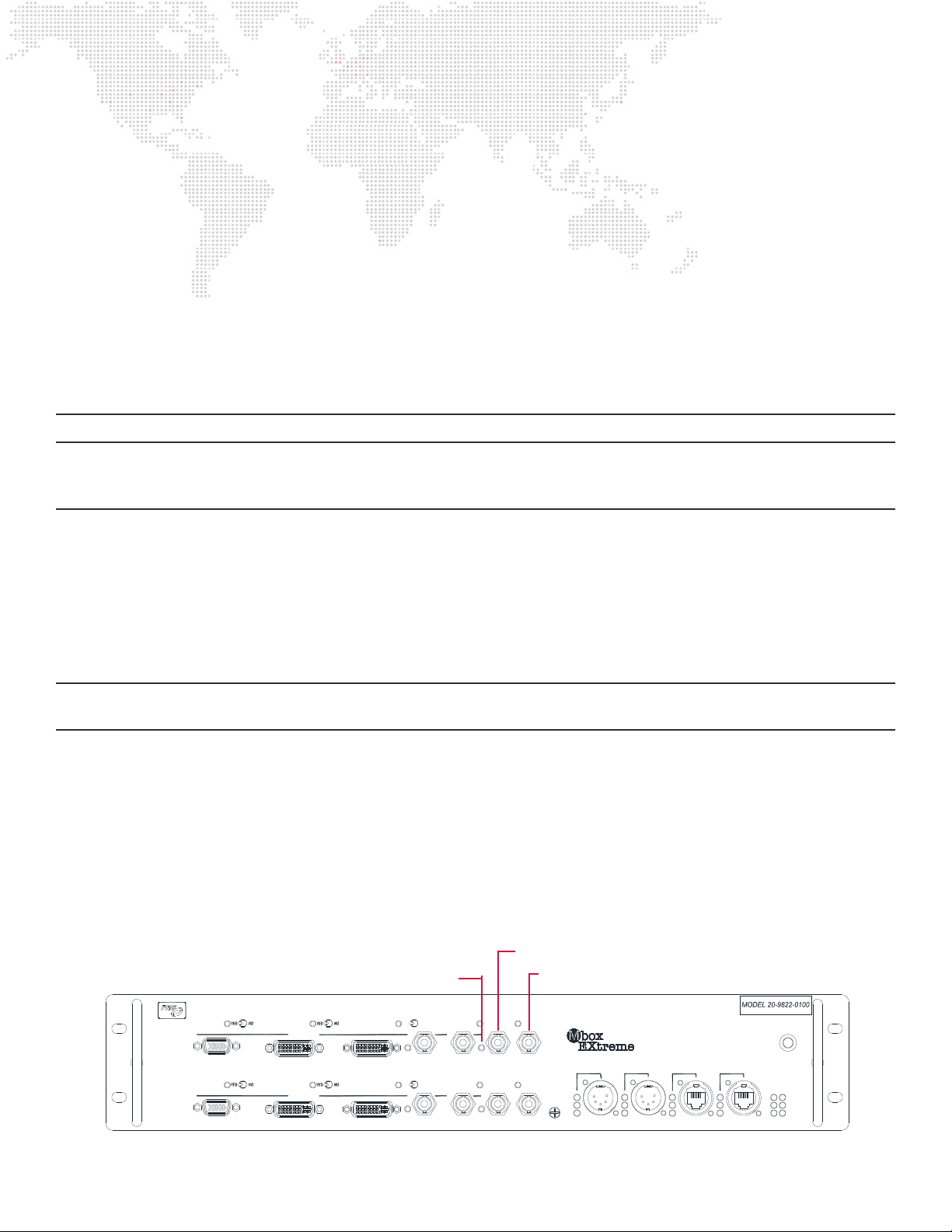
Also, as noted previously, always select the FIRST frequency that matches the desired output frequency, as the other
options with the same value may not result in the correct output frequency.
Example - To get the I/O Module to output 720p @ 59.94Hz:
Step 1. Open the System Preferences > Displays pref pane on the computer.
Step 2. Using the switch combinations outlined on page 18, change the EDID set on both outputs of the I/O
Module to the PRG-MbE 59.94Hz set.
Step 3. On the Displays pref pane, click the Detect Displays button. Then set the resolution and frequency of both
displays to be 1280 x 720 and 59.94Hz respectively.
Step 4. On the Mbox application’s Outputs tab, conrm that the display assignment pop-up for each output shows
“PRG-MbE 59.94 (1280x720) @ 59.88 Hz”.
Note: The pop-up says 59.88 Hz (not 59.94 Hz) due to the custom timing required for the I/O Module to generate SDI.
GENLOCK (GENERATOR LOCK)
Overview
The function of genlock is to synchronize the video output or capture frequency and sync point of one or more devices
to a reference signal. This functionality is important in video systems when cameras are being used or when routers or
switchers are being used. The reference sync input causes the device to start drawing or capturing each frame of video
at the correct moment (the “sync point”). With all the devices in a video system being synchronized in this manner,
tearing on outputs or between outputs, and tearing when switching between sources can be avoided.
Note: In most cases, the output/capture device must already be set to output or capture at the exact same refresh
frequency as the reference signal. This is true for the Mbox system.
Genlock and the Dual I/O Module
A genlock reference signal that is input to the Dual I/O Module can be used to tell the Mac Pro computer’s graphics card
when to start drawing each frame of video. If more than one Mbox server is used, they can all be genlocked so that all
the Mbox servers in the system will start drawing frames at the same time.
The I/O Module acts as the receiver of the genlock reference signal and compares that frequency and sync point to the
current output of the Mac Pro computer’s graphics card. If the computer is outputting video at the same frequency as
the reference signal, then the I/O Module sends a control signal to the computer’s graphics card to bring the output’s
sync point into lock with the reference signal’s sync point.
Genlock
Indicator LED
PR E VI EW 1
ED ID CA PT UR E
A
SD I 1
ED ID CA PT UR E
A
SD I 2
ST A GE B L AC K OU T
VG A 1
ST A GE B L AC K OU T PR E VI EW D IM
VG A 2
PR E VI EW D IM
OUT P UT 1
DVI 1
OUT P UT 2
DVI 2 PR E VI EW 2
B
B
AC TI VE US B
IN
OUT
GE NL OC K 1
AC TI VE
IN
OUT
GE NL OC K 2
Genlock In
Genlock Out
US B
DMX R x
RDM R x
RDM Tx
INP UT 1
TM
Dual I/O Module
DMX
INP UT 2
E THE R NE T
PO R T 1
PO R T 2
PO WE R
CO MP UTE R
LINK
Tx
Rx
A
B
MBOX® 2016 DUAL OUTPUT HARDWARE MANUAL
23
Page 29
Note: The I/O Module provided with the Mbox 2016 Dual Output system supports both tri-level (HD) and bi-level
(composite) sync input. However, the I/O Module provided with the older Mbox EXtreme system only supports bi-level
sync.
The I/O Module can also output a pseudo-genlock signal to other devices, if desired. Genlock Output connectors are
provided on the I/O module for this purpose. However, because this signal is not a true genlock signal, it should only be
used to sync one Mbox server to another and should not be used to sync other equipment to an Mbox.
Note that in normal conguration, only the top pair of Genlock connectors on each I/O Module are active.
CAUTION! The Genlock Out connector should not be used as a daisy-chain pass-through, as the output signal is locally
generated and adds propagation delay. If the genlock output is used, it should be routed to the input of a D/A and then
the individual outputs of the D/A connected to the genlock inputs of the other Mbox I/O Modules.
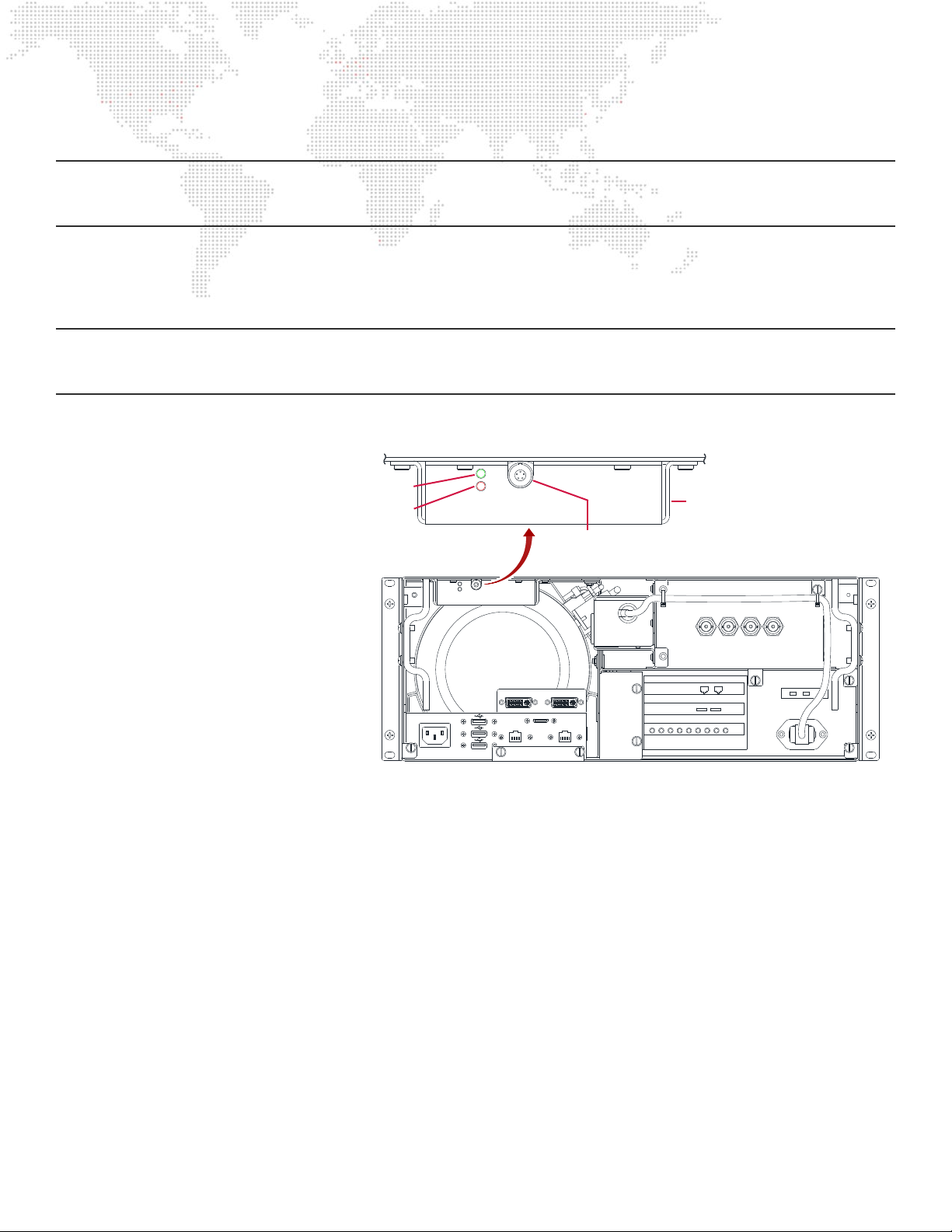
The Mbox genlock functionality uses a
connection between the rear of the I/O
Module and the Genlock Controller at
the rear of the xMac unit. An additional
cable connects the Genlock Controller
to the Mac Pro computer. The Genlock
Controller is located behind the
Green LED
Red LED
Connection to
I/O Module
Genlock Controller Detail
Connection to
Mac Pro
(on rear)
computer, above the USB connectors
on the rear of the xMac unit. It has two
indicator LEDs - one red and one green -
234 1
which function as follows:
+ If the controller is receiving power
from the I/O Module but no sync
data, the red LED will turn on.
+ When the controller is receiving sync
data (i.e. when a genlock input is
connected to the I/O Module), the
100-240V. 50-60Hz
DVI 1 DV I 2
1
EN ET A ENE T B
2
3
HDMI
green LED will turn on and the red
LED will turn off.
When a genlock signal is connected to the I/O Module, the Genlock Indicator LED to the left of the Genlock In connector
provides information on the state of the genlock sync:
+ When the genlock signal is rst connected to the I/O Module, the Genlock Indicator LED will start to ash. This is to
indicate that the module has recognized the presence of an incoming signal and is attempting to synchronize to it.
+ Once synchronization has occurred, the LED will stop ashing and stay illuminated. It may take 20 - 40 seconds for
the synchronization process to complete, so it is advisable to establish sync a few minutes before needed.
+ If the indicator LED ashes rapidly when genlock is connected, this indicates that the input frequency does not
match the frequency that the computer’s graphics card is outputting - i.e. it is too fast or too slow. Remember that
the computer must already be congured to output the correct matching frequency in advance!
+ If the indicator LED ashes rapidly then turns off altogether, this is an indication that the input signal is not a standard
sync signal. Check the type and quality of the signal.
24
MBOX® 2016 DUAL OUTPUT HARDWARE MANUAL
Page 30

To ensure that genlock input and output work successfully, make sure that all devices being synchronized are congured
to refresh at identical frequencies. If the Mbox computer is set to output video with a refresh rate of 59.94Hz, then it
can only genlock to a reference sync of 59.94Hz and its output should only be connected to another device that is set to
refresh at 59.94Hz. Similarly, if you intend to synchronize Mbox video output to a video source refreshing at 50Hz, the
computer must output video with a refresh rate of 50Hz. Please note that not all video refresh rates are available on all
devices or are compatible with all devices.
CAUTION! Both outputs of the Mac Pro computer must use the same EDID and the same resolution and frequency in
order for the genlock to work correctly. It is not possible to output at 59.94Hz from one output and 50Hz from the other
output and sync one or both outputs to genlock. Additionally, attempting to synchronize the computer’s output to an
external source with a different refresh rate, however slight, will not work.
DMX AND ETHERNET
Overview
In addition to its video conversion and distribution capabilities, the Dual I/O Module also provides connections for
DMX input and Ethernet input/output. Inside the I/O Module, a circuit board separate from the video sections handles
these two functions. Although there is no conguration possible (or necessary) for these connections, there are some
important considerations when they are being used.
DMX Input 1
(Universe 0)
DMX Input 2
(Universe 1)
Ethernet
ST A GE B L AC K OU T
VG A 1
ST A GE B L AC K OU T PR E VI EW D IM
VG A 2
PR E VI EW D IM
OUT P UT 1
DVI 1
OUT P UT 2
DVI 2 PR E VI EW 2
ED ID CA PT UR E
A
PR E VI EW 1
ED ID CA PT UR E
A
SD I 1
SD I 2
B
B
AC TI VE US B
IN
OUT
GE NL OC K 1
AC TI VE
IN
OUT
GE NL OC K 2
TM
PO WE R
Dual I/O Module
DMX R x
RDM R x
RDM Tx
INP UT 1
DMX
INP UT 2
US B
DMX LED
Indicators
E THE R NE T
PO R T 1
Ethernet LED
Indicators
(Front)
CO MP UTE R
LINK
Tx
Rx
A
PO R T 2
Ethernet LED
Indicators
(Rear)
B
DMX
The Dual I/O Module has two DMX input connectors on its front panel. The I/O Module converts the two received DMX
universes into two Art-Net universes. The resulting Art-Net is placed onto the Ethernet section of the I/O Module for
distribution on any of the Ethernet connectors.
The two DMX universes are always converted to the same Art-Net universes, and this cannot be changed. The left-hand
DMX connector (Input 1) is always converted to Art-Net universe 0. The right-hand DMX connector (Input 2) is always
converted to Art-Net universe 1.
Note: Because the Mbox v4 software can use more than two universes for control, the use of the DMX inputs is only
advisable for simple shows or for auxiliary purposes.
Each DMX input connector has three indicator LEDs that show the status of the input signal. The DMX Rx indicator LED
will illuminate if a valid DMX signal is received. The RDM Rx and Tx LEDs will illuminate to show RDM activity. However,
the Mbox system does not use RDM so these LEDs can be ignored.
MBOX® 2016 DUAL OUTPUT HARDWARE MANUAL
25
Page 31

Ethernet
The I/O Module has a total of four Ethernet connectors - two on the front panel and two on the rear. The Ethernet
section of the I/O Module incorporates an Ethernet switch, meaning that all four connectors to be on the same physical
Ethernet network. This means that any Ethernet data that is present on one of the connectors will also be present on all
of the other connectors.
One of the connectors on the rear of the I/O Module (typically Ethernet A) is connected to the Mac Pro computer,
allowing Ethernet to be transmitted between the front of the I/O Module and the computer. This allows control signals
such as Art-Net or sACN to be connected to the front of the I/O Module and then be passed to the computer for use by
the Mbox application. Either of the front panel connectors can be used for this purpose. The second connector can be
left without a connection or a second cable can be used to distribute that same Ethernet control signal to other devices.
Note: The second Ethernet connector on the rear of the I/O Module is typically not used but may be used if desired by
simply connecting a cable.
It is important to note that the Ethernet switch in the I/O Module is only capable of 10/100Mb speeds and is not a gigabit
switch. Additionally, the switch has no management capabilities. These limitations mean that there are some situations
where Ethernet should not be connected to the I/O Module and should be connected to one of the Ethernet connectors
on the back of the Mbox rack instead:
+ Large control networks (more than 30 universes) may be negatively affected by the slow speed of the I/O Module’s
non-gigabit Ethernet speed.
+ Because it has no management capability, the switch performs no routing. This means that multicast trafc (e.g.
sACN) cannot be ltered and will be present on all the Ethernet connections to/from the I/O Module.
+ Some lighting consoles’ processing networks (e.g. MA-Net) require gigabit speeds for proper function. Therefore if
the Mbox computer needs to be on the same physical network and the console, the I/O Module Ethernet connectors
should not be used.
+ Tasks such as CITP/MSEX streaming and content synchronization benet from fast networks with enough bandwidth
for the amount of data being transmitted. Using the I/O Module’s Ethernet connections for either of these purposes
is not recommended.
Each Ethernet connector on the I/O Module has three LED indicators. The indicator LEDs for the two front panel
Ethernet connectors are located adjacent to the connectors. The indicator LEDs for the two rear panel connectors are
located as a pair on the far right-hand side of the I/O module, and are labeled as “Computer”. The Ethernet A connector
on the rear of the I/O Module - which is connected to the Mac Pro computer - is the I/O Module’s third Ethernet
connection. Therefore its status is shown on the left-hand set of LEDs in this pair.
The LED indicators show Link status (an active electrical connection) as well as Ethernet Rx and Tx. While no data-
specic information can be taken from the state of the indicator LEDs, the illumination of the Link LED, coupled with the
illumination or ashing of the Rx and/or Tx LEDs indicates that Ethernet data is passing in and out of the I/O Module’s
switch hardware.
26
MBOX® 2016 DUAL OUTPUT HARDWARE MANUAL
Page 32

1.
3.
CAPTURE CARD
This chapter provides information regarding the use of the Blackmagic Decklink Quad capture
card for video input and output.
+ OPERATIONAL OVERVIEW
+ INPUT
+ OUTPUT
Page 33
OPERATION OVERVIEW
Function
Note: For an overview of the capture card components and connections, refer to “Sonnet xMac Pro” on page 7.
The Mbox 2016 Dual Output server hardware includes a Blackmagic Decklink Quad capture card. This card is located in
the PCIe card cage section of the Sonnet xMac Pro unit. The capture card provides up to four simultaneous SDI inputs
in standard conguration. Optionally, the card can be used to generate up to four simultaneous SDI outputs.
Note: The Decklink Quad capture card has four independent input/output sections, with each only capable of input or
output, but not both at the same time. Therefore, while it is possible to have four inputs or four outputs, it is not possible
to have four inputs
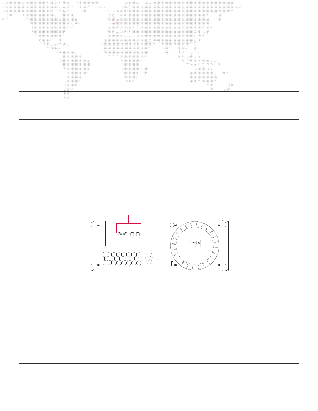
In the standard hardware conguration, the four input connectors of the capture card are internally connected to the rear
of the four BNC connectors on the front of the Mbox rack. The internal connections are made with a special adapter
cable due to the DIN 1.0/2.3 connectors on the capture card.
Input
In standard conguration, no changes need to be made to the capture card’s conguration or connections to support
use for video input. SDI video signal can be connected to the BNC connectors on the front of the xMac unit and the
Mbox software set up to enable and congure the appropriate input(s). Each input must be enabled and congured
separately.
and
four outputs. It is only possible to have a combination of inputs and outputs that totals four.
BNC Connections
to Decklink Card
VID EO IN PU T
2 3 41
The Decklink Quad card supports SD/HD SDI input (SMPTE standard 259M and 292M) with a bitrate of up to 1.5Gb/sec.
The following standard formats are supported:
+ NTSC - 720x480 @ 59.94Hz
+ PAL - 720x576 @ 50Hz
+ 720p - 1280x720 @ 50/59.94/60Hz
+ 1080i - 1920x1080 @ 50/59.94/60Hz
+ 1080p - 1920x1080 @ 23.98/24/25/29.97/30Hz
CAUTION! The capture card does not support SMPTE 424M with bitrates up to 3.0Gb/sec. This means that 1080p
formats with frequencies above 30Hz are not supported.
28
MBOX® 2016 DUAL OUTPUT HARDWARE MANUAL
Page 34

The capture card has conguration settings in both the System Preferences > Blackmagic Desktop Video pref pane
and on the Preferences tab of the Mbox application itself. For normal operation, no changes need to be made in the
Blackmagic Desktop Video pref pane, all conguration changes are made in the Mbox application.
Refer to Chapter 6: Video Input, page 144 of the Mbox software user manual for information about conguring the video
inputs on the Mbox software’s Preferences tab.
Output
While video output through Blackmagic devices is fully supported in the Mbox v4 software, the Mbox 2016 Dual Output
server is not set up by default. There are several steps required to enable and congure video input.
Step 1. On the Preferences tab of the Mbox application, conrm that the section to be used for video output is not
being used for video input. If this is the case, the input must be disabled or a different section of the card
must be used.
Step 2. On the capture card at the rear of the xMac unit, move the DIN 1.0/2.3 cable from the current input
connector to the paired output connector.
234 1
Standard connections
between front panel
and Decklink Card
DV I 1 DV I 2
1
E NE T A E NE T B
2
HDMI
Move cables here to
change from input to
output
In 1
In 2In 3In 4
Out 1
Out 2Out 3Out 4
Genlock In
Step 3. Open the System Preferences > Blackmagic Desktop Video pref pane and adjust the following output
properties as desired:
a. PsF Output (on/off) - for Progressive Segmented Frame output, the off option should be selected unless
PsF is specically required.
b. Remove Field Jitter on Pause (on/off) - the off option is recommended.
c. Idle Output (Black/Last Frame Shown) - the Black option is recommended.
d. Output Format - this property does not need to be set, and will be set in the Mbox application instead.
Step 4. On the Outputs tab of the Mbox application create an output and congure it to use the appropriate
Blackmagic output (Decklink SDI 1-4).
Step 5. Select the output format from the pop-up that is to the right of the display selection pop-up. This will cause
the output to resize automatically to match the resolution of the selected format.
Step 6. Connect a cable between the appropriate BNC connector on the front of the Mbox rack and the receiving
device.
Note: The genlock input connector on the capture card can be used to lock the outputs to external reference sync.
MBOX® 2016 DUAL OUTPUT HARDWARE MANUAL
29
Page 35

Notes
30
MBOX® 2016 DUAL OUTPUT HARDWARE MANUAL
Page 36

4.
USB/AUDIO INTERFACE
This chapter provides information regarding the use of the Focusrite Scarlett 2i2 USB/Audio
interface.
+ OPERATIONAL OVERVIEW
+ AUDIO OUTPUT
+ AUDIO INPUT (LTC)
Page 37

OPERATION OVERVIEW
TOP VIEW
L R
RED
BLACK
LEFT RIGHT
BLACK BOOT
RED BOOT
LE FTRIG HT
LIN E OUT P UTS
USB
BACK VIEW
SECTION
"A-A"
AA
Function
Note: For an overview of the USB/Audio interface components and connections, refer to “Focusrite Scarlett 2i2 USB/
Audio Interface” on page 10.
The Mbox 2016 Dual Output server hardware includes a Focusrite Scarlett 2i2 USB/Audio interface. This device is
located in Mbox rack immediately above the Sonnet xMac unit. The audio interface provides two channels of audio
input and two channels of audio output. The standard connector for both input and output is 3pin XLR, and the inputs
will also accept a 1/4” TRS plug.
For use with the Mbox application, the inputs on the audio interface are typically used for timecode input using SMPTE
LTC timecode. The outputs are typically used for playout of audio from the Mbox application.
Note: The standard audio interface only supports two-channel (stereo) audio output. If more than two channels of audio
output are required, an alternate audio interface device should be used.
Input Gain Headphones
1 2
0
10
GAIN
LINE INST LINE INST OFF ON
scarlett 2i2
Audio Input
XLR (1 & 2)
The Focusrite Scarlett 2i2 audio interface has a USB indicator LED that shows when the device has a USB connection to
48v
MONITOR
0
10
48V
GAIN
DIRECT
MONITOR
MonitorLine/Inst
Direct
Monitor
USB
LED
0
10
R IGH TLE F T
BAL ANC E D
AUDIO O UT
Audio Output
XLRs (L & R)
the Mac Pro computer. This connection is required for any audio input or output using the device.
Input
Audio input for the Mbox 2016 Dual Output server is typically only a single channel. This single channel of input audio is
in the form of Linear Time Code (LTC) which is often called SMPTE timecode. LTC is usually a balanced line-level signal,
but the audio interface will also accept an unbalanced and/or instrument-level input.
For audio input into Mbox, the audio source and input channel must be selected on the application’s Preferences tab.
With the standard audio interface, the source selection would be “Scarlett 2i2 USB”. It does not matter which input
channel (1 or 2, left or right) is used for LTC input. But depending on which input channel is receiving the signal, this
active channel must be selected. Refer to “Audio Input” on page 102 of the Mbox software user manual for information
on conguring the Mbox application for audio input.
The Scarlett 2i2 interface has several adjustments that can be made to affect the input signal:
+ Input Gain - The colored LED ring around the knob will be colored green if signal is at a good level, red if the signal is
too high. Start with the knob at 12 o’clock and adjust gain if signal drops out intermittently.
+ Line/Inst - For standard LTC, this switch should be to the left, in the Line position.
+ 48v - This button should be in the off position (red LED off)
+ Direct Monitor - If only using the audio input, the position of this switch doesn’t matter. But if using both the audio
input and output, this switch should be in the Off position.
32
MBOX® 2016 DUAL OUTPUT HARDWARE MANUAL
Page 38

Output
Audio playback in Mbox is supported with audio embedded in movies and also with “sidecar” audio les. Either of these
playback options can have between two and twenty-four channels of audio. Audio playback and output from the Mbox
2016 Dual Output server is typically two channels - stereo. And as noted above the Scarlett 2i2 audio interface is limited
to two channels of output.
For audio output from Mbox, the audio destination and number of channels must be selected on the application’s
Preferences tab. With the standard audio interface, the destination selection would be “Scarlett 2i2 USB” and the
number of channels would normally be set to “2”. When setting the number of channels, some exceptions do exist,
depending on the number of channels in the actual audio le. Refer to “Audio Output” on page 99 of the Mbox software
user manual for information on conguring the Mbox application for audio output.
The Scarlett 2i2 interface has several adjustments that can be made to affect the output signal:
+ Direct Monitor - This switch, when turned to the On position, causes the input audio to be routed directly to the
output. When outputting audio from the Mbox application, this switch should be turned off.
+ Monitor - This knob controls the output level of the XLR outputs on the right side of the unit. Start with the knob at
12 o’clock and adjust as required.
+ Headphones - The 1/4” TRS jack can be used to monitor the output. The level knob adjusts the level of the
headphone output only.
MBOX® 2016 DUAL OUTPUT HARDWARE MANUAL
33
Page 39

Notes
34
MBOX® 2016 DUAL OUTPUT HARDWARE MANUAL
Page 40

1.
A.
MAINTENANCE
This appendix contains procedures for extended care of the Mbox 2016 Dual Output server.
+ ROUTINE MAINTENANCE
+ PCIE CARDS
+ ADDITIONAL PERIPHERALS
Page 41

ROUTINE MAINTENANCE
Cleaning or Replacing the Air Filter
To clean/remove air lter:
Step 1. Disconnect power from the server.
Step 2. At the front of the rack, remove six screws to release front panel.
Step 3. Remove the front panel and air lter.
Step 4. Clean lter with compressed air or water. If water is used, allow to dry fully before use.
Step 5. Re-install lter and front panel.
36
Figure B-1: Air Filter Removal
MBOX® USER MANUAL
Page 42

Removing the Computer
The Mac Pro computer can be removed to be cleaned or replaced, or to have additional peripherals plugged into it.
To remove computer:
Step 1. At the rear of the rack, disconnect all power, USB, Ethernet, and DVI cables from the rear left side of
the Sonnet xMac unit. Make sure to also disconnect the LEMO connector from the front of the Genlock
Controller, the 3.5mm plug from the back side of the Genlock Controller, and the FireWire cable between the
computer and the Power Relay unit.
Step 2. At the rear of the xMac unit, loosen the three retaining fasteners that hold the computer enclosure into the
xMac unit.
Step 3. At the front of the rack, remove the front panel. Refer back to “Figure B-1: Air Filter Removal” on page
36.
Step 4. Carefully slide the computer enclosure out of the case, checking for cables or connectors that may become
caught. (Figure B-2).
Figure B-2: Computer Removal
MBOX® 2016 DUAL OUTPUT HARDWARE MANUAL
37
Page 43

Removing the PCIe Card Cage
The PCIe card cage in the Sonnet xMac unit can be removed from the case to be cleaned or replaced, or to have
different PCIe cards inserted.
To remove PCIe card cage:
Step 1. At the rear of the rack, disconnect all power, Thunderbolt, Ethernet, and video cables from the rear right
side of the Sonnet xMac unit. The Thunderbolt cable has shell with a screw-down retainer. The Din 1.0/2.3
connectors for the capture card have a locking collar that must be retracted when disconnecting the cable.
Step 2. At the rear of the xMac unit, loosen the ve retaining fasteners that hold the card cage into the xMac unit.
Step 3. At the front of the rack, remove the front panel and air lter. Refer back to “Figure B-1: Air Filter Removal”
on page 36.
Step 4. Carefully slide the card cage out of the case, checking for cables or connectors that may become caught.
(Figure B-3).
38
Figure B-3: Replacing PCIe Card Cage
MBOX® 2016 DUAL OUTPUT HARDWARE MANUAL
Page 44

PCIe CARDS
Overview
The Mbox 2016 Dual Output server includes three PCIe cards that are pre-installed in the PCIe card cage that is part of
the Sonnet xMac Pro unit. The standard cards are:
+ Slot 1 (top) - Small Tree NIC.
- This card has two auxiliary gigabit Ethernet interfaces.
+ Slot 2 (middle) - Sonnet Tempo Pro dual SSD card.
- This card holds the 2TB SSD RAID that holds the Mbox content.
+ Slot 3 (bottom) - Blackmagic Decklink Quad capture card.
- This card provides the SDI input for the Mbox software.
Replacing PCIe Cards
If it is necessary to replace any of the PCIe cards in the card cage, follow the refer back to “Figure B-3: Replacing PCIe
Card Cage” on page 38 for information on removing the card cage for access to the cards. Then refer to Technical
Bulletin MBX-024 for further instruction for the removal of the individual PCIe cards.
ADDITIONAL PERIPHERALS
Overview
From time to time it may become necessary to connect additional peripheral devices to the Mbox 2016 Dual Output
server. For the most part these devices will be connected to the available connectors on the front or rear of the rack.
In the case of added/alternate video output, connections may need to be altered on the Mac Pro computer’s interface
panel. For example, to switch to a 4K displayport video output, it will be necessary to disconnect one of the DVI outputs
from the computer and connect the displayport cable in its place.
+ Thunderbolt Connector 1 is used for video output 1.
+ Thunderbolt Connector 2 is used for video output 2 - Use this connector for displayport cable with 4K output.
CAUTION! Do not attempt to connect more than two video cables directly to the Mac Pro computer. Do not disconnect
the other Thunderbolt cables as doing so will result in a lack of functionality for other parts of the Mbox system.
1 2
3 4
Thunderbolt connectors 1 and 2
TB #
1 3 5
2 4 6
are used for video output
Figure B-4: Mac Pro Interface Panel
B
HDMI
A
MBOX® 2016 DUAL OUTPUT HARDWARE MANUAL
39
Page 45

Notes
40
MBOX® 2016 DUAL OUTPUT HARDWARE MANUAL
Page 46

B.
INTRA-RACK CONNECTIONS
This appendix contains a diagram of the connections made between items in the Mbox 2016
Dual Output rack
+ DIAGRAM
Page 47

INTRA-RACK CONNECTIONS
Diagrams
This diagrams below show the cable connections between equipment in the Mbox 2016 Dual Output rack. For added
clarity, colors have been assigned to specic equipment and signal types.
MacPro Connections
USB
USB 2
USB 1
USB 3
IEC
USB
Genlock Controller
Sync
In
Sync In
DVI 2
USB
MDP to DVI Adapter
for DVI 1
Thunderbolt cable to
Sonnet PCIe Bridge
Sync
Out
Sync
1
Video DVI 1
Ethernet
USB
Sync Cable from
bottom of MacPro
FW800
Sync
2
Video DVI 2
AC Power
AC Power
MDP to DVI Adapter
AC
IN
Enet AEnet
USB
Thunderbolt to
FireWire Adapter
HDMI cable to
Rear Panel
IEC cable from
Rear Panel
AC Power
B
USB 4
USB
TB 2 TB 1
for DVI 2
TB 4 TB 3
TB 6 TB 5
Enet 1 Enet 2
HDMI
Mbox I/O Module Rear Panel
DVI 1
USB 1
USB 2
Mbox 2016 Dual Output Cable Connections
Note: Dashed lines denote cables that run from the Mac Pro to items in the rack.
Solid lines denote cables that run from connections on the rear of the rack to other
connections on the rear of the rack.
MDP to DVI
Sync
MDP to DVI
DVI Bulkhead
Bulkhead 1Bulkhead 2
Sonnet xMac Rear Panel A
AC
IN
DVI
DVI
DVI 1
DVI 2
Enet 1Enet
2
USB
USB
Sonnet xMac Front Panel
USB
USB
Relay Unit
AC
USB
AC Power
FW800
IN
USB 1
USB 2
USB 3
Video In Panel (Front of Sonnet xMac)
BNC Connectors
1 2 3 4
Thunderbolt
AC
OUT
AC Power
Focusrite Scarlett 2i2 Rear Panel
USB
Audio Out Left
Audio Out Right
Sonnet xMac Rear Panel B
(PCI Card Cage)
DIN Coax Connectors
Out
Out
In 3
3
2
Video In 1
Focusrite Scarlett 2i2 Front Panel
USB
(These are ordered from RIGHT to LEFT when viewed from the rear!!)
Out
In 4
4
Video In 4
Video In 3
Video In 2
XLR3M Connectors
L R
Out
In 2
1
1/4” TS Connectors
R L
In 1 Ref
T-Bolt
AC
IN
42
MBOX® 2016 DUAL OUTPUT HARDWARE MANUAL
Page 48

C.
SPECIFICATIONS
This chapter provides specication information for the Mbox 2016 Dual Output server
+ MBOX RACK
+ DUAL I/O MODULE
+ COMPUTER
+ SONNET XMAC PRO
+ FOCUSRITE SCARLETT 2I2
Page 49

SPECIFICATIONS
Mbox Rack
Equipment:
+ Custom single-server rack
+ 1500VA UPS
+ Mbox Dual I/O Module
+ Sonnet xMac Pro
+ Apple Mac Pro computer
+ Focusrite Scarlett 2i2 USB/Audio interface
+ Apple keyboard
+ Logitech Marble Man trackball
+ Dimensions ( L x W x H): 30” x 24” x 26”
+ Weight: 236 LBS
Dual I/O Module
PRG Proprietary Dual I/O Module:
+ Dual Output video sections
+ EDID management - three built-in sets, capture from connected display
+ Video format conversion - DVI to VGA and SDI
+ Video output D/A for DVI and SDI output with independent dimming
+ Input
- DVI single-link 1920 x 1200 maximum
+ Output
- DVI: single-link 1920x1200 maximum
- VGA: 1920x1200 maximum
- SDI: SMPTE 259M, SMPTE 292M (1.5Gb/sec limit)
+ Built-in hardware dimming with program monitor for automatic blackout
+ Genlock input for interface with Mac Pro computer - bi/tri-level sync
+ DMX to Art-Net conversion - two universes
+ Built-in 10/100MB Ethernet switch - four ports
+ 100 - 240v 50-60Hz
44
MBOX® 2016 DUAL OUTPUT HARDWARE MANUAL
Page 50

Computer
Apple Mac Pro 6,1 Late 2013 (https://www.apple.com/mac-pro/):
+ 8-core 3.0GHz processor
+ 32 GB RAM
+ 256 GB Flash Storage
+ Dual D700 GPU
- Includes custom modication for genlock functionality with Mbox Dual I/O Module
+ 100-240v 50-60Hz
Sonnet xMac Pro
Sonnet xMac Pro Server expansion system (http://www.sonnettech.com/product/xmacproserver/index.html):
+ Rack mount computer enclosure
- Thunderbolt 2 interface to PCIe card cage
- Front/rear-mounted I/O connections for USB, Ethernet, DVI, Thunderbolt
+ Small Tree P2EG-2-T GbE Dual Port
+ Sonnet Tempo SSD Pro Plus with 2x 1TB Samsung 850 Pro SSD in RAID 0 conguration
+ Blackmagic Decklink Quad capture card
+ 115-230v 50-60Hz
Focusrite Scarlett 2i2
Focusrite Scarlett 2i2 USB interface (https://us.focusrite.com/usb-audio-interfaces/scarlett-2i2):
+ 2-channel audio input and output
+ USB bus-powered
+ 44.1kHz, 48kHz, 96kHz, 192kHz sample rates
+ Adjustable input/output gain
+ XLR balanced/unbalanced input and output
MBOX® 2016 DUAL OUTPUT HARDWARE MANUAL
45
 Loading...