

Page 1

WWW.PRG.COM
PRG SERIES 400®
7-PORT ETHERNET SWITCH &
10-PORT ETHERNET SWITCH
USER MANUAL
Page 2

AutoPar®, Bad Boy®, PRG Series 400®, Mbox Extreme®, V676®, Virtuoso®, Virtuoso® DX, and Virtuoso® DX2,
are trademarks of Production Resource Group, LLC, registered in the U.S. and other countries.
All other brand names which may be mentioned in this manual are trademarks or registered trademarks of their respective companies.
This manual is for informational use only and is subject to change without notice. Please check www.prg.com for the latest version.
PRG assumes no responsibility or liability for any claims resulting from errors or inaccuracies that may appear in this manual.
PRG Series 400® Ethernet Switch User Manual
Version as of: October 18, 2010
PRG part number: 02.9801.0001 B
Production Resource Group
Dallas Office
8617 Ambassador Row, Suite 120
Dallas, Texas 75247
www.prg.com
PRG Series 400® Ethernet Switch User Manual
©2006-2010 Production Resource Group, LLC. All Rights Reserved.
Page 3

INTRODUCTION
About This Manual
This manual provides necessary information regarding product safety, installation, and operation for the following
PRG equipment:
+ PRG Series 400® 10-Port Ethernet Switch (20.9801.0200)
+ PRG Series 400® 7-Port Ethernet Switch (20.9801.0200.07)
Familiarizing yourself with this information will help you get the most out of your PRG product.
WARNING: It is important to read ALL accompanying safety and installation instructions to avoid damage to
the product and potential injury to yourself or others.
Additional Documentation
For more information on related equipment, refer to the following PRG manuals:
+ PRG Series 400® Power and Data Distribution System User Manual (02.9680.0001.xx)
+ PRG Series 400® Power and Data Distribution System Service Manual (02.9680.0010)
+ Virtuoso® Node User Manual (02.9669.0001)
+ Virtuoso® Node Plus User Manual (02.9801.0301)
For more information regarding DMX512 systems, refer to the DMX512/1990 & AMX 192 Standards publication
available from United States Institute for Theatre Technology, Inc. (USITT).
USITT
6443 Ridings Road
Syracuse, NY 13206-1111 USA
1-800-93USITT
www.usitt.org
For more information regarding Art-Net protocol, refer to the specification for Art-Net II Ethernet Communication
Standard available from Artistic Licence Ltd.
Artistic Licence (UK) Ltd (Registered Office)
24 Forward Drive, Christchurch Avenue,
Harrow, Middlesex, HA3 8NT, United Kingdom
+44 (0)20 88 63 45 15 (phone)
+44 (0)20 84 26 05 51 (fax)
www.artisticlicence.com
For additional documentation, please visit our support tech center at: www.prg.com/support
PRG SERIES 400® ETHERNET SWITCH USER MANUAL 1
Page 4

Customer Service
For technical assistance, contact the PRG International Service Center or contact your nearest PRG office. Contact
information for all PRG office locations can be found on our website at: www.prg.com/about-us/locations/
PRG Dallas (International Service)
8617 Ambassador Row, Suite 120
Dallas, Texas 75247 USA
Phone: 214.630.1963
Fax: 214.630.5867
Service Fax: 214.638.2125
Service Email: [email protected]
For additional resources and documentation, please visit our website at: www.prg.com
2 PRG SERIES 400® ETHERNET SWITCH USER MANUAL
Page 5
OVERVIEW
10-Port Ethernet Switch
The PRG Series 400 10-Port Ethernet Switch provides a powerful and convenient interface between V676®,
Virtuoso®, or DMX512 control consoles and their control equipment. The 10-Port Ethernet Switch offers two types of
connections: isolated copper Ethernet ports and fiber optic ports. The fiber optic ports provide the ability to send fast
and reliable information up to 2 kilometers away without the need for repeaters using Virtuoso Fiber Optic Cable. The
copper Ethernet connections offer the ability to combine standard copper connections with fiber optic transmissions.
Note
: Copper connections are limited to a maximum distance of 300 feet.
The 10-Port Ethernet Switch automatically determines the speed of each network connection based on the
equipment connected to the switch and supports multiple connections with transmission and reception occurring
simultaneously.
Features:
+ Seven isolated copper Ethernet ports for input of 10Base-T and 100Base-TX standard signal (Neutrik®
EtherCon® connectors).
+ Three fiber optic Ethernet ports for transmission of 100Base-FX standard signal. Two ports allow use of a Fiber
Optic Cable
+ Automatic detection and configuration of input signal speed.
+ Link, Transmission, and Reception status LEDs for all ports.
+ Neutrik® PowerCon® connector for input AC supply.
+ DC power status LED.
+ Standard 1U 19" rack mount chassis.
input
connector and one port allows use of a Fiber Optic Cable
output
connector.
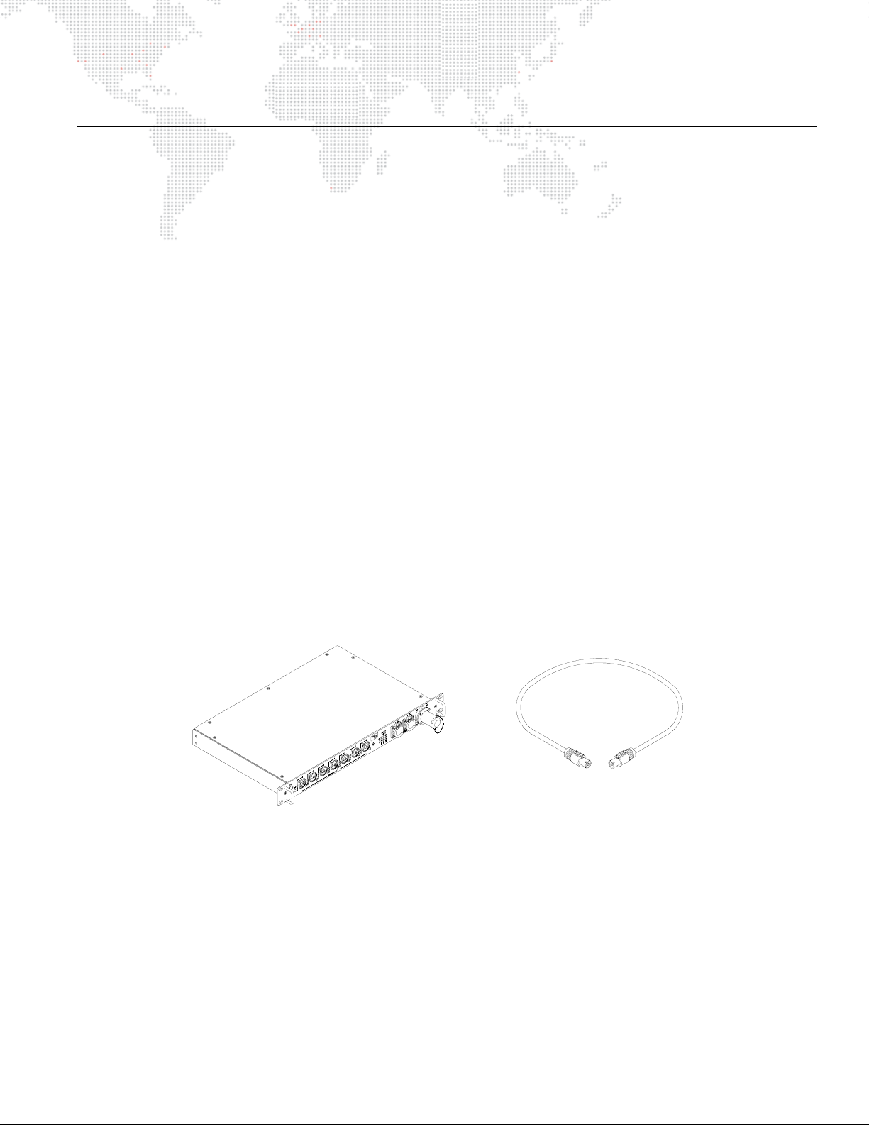
Included Items
The following illustration shows all items included with this model:
PRG Series 400 10-Port
Ethernet Switch (20.9801.0200)
Figure 1: 10-Port Ethernet Switch Included Items
AC Line Cord 208V
PowerCon® Cable Assembly
(25.9801.0214)
PRG SERIES 400® ETHERNET SWITCH USER MANUAL 3
Page 6
Controls and Indicators
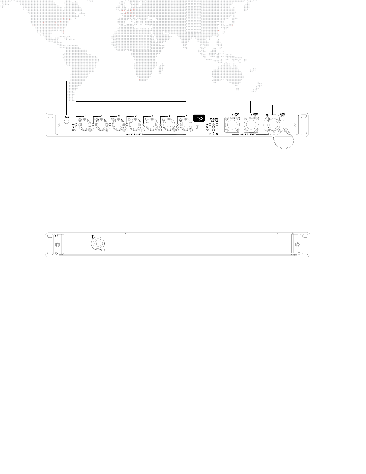
The Series 400 10-Port Ethernet Switch contains the following connections and LED indicators.
DC Power Indicator -
indicates AC power is applied.
10/100 Base T Connections -
input/output ports for standard signals.
Ethernet LEDs -
indicates valid Ethernet
link, transmit and receive
for each connection when lit.
Fiber Optic Input -
ports for fiber optic
cables with input
connectors.
Fiber Data LEDs -
indicates valid Fiber
link, transmit and receive
for each connection when lit.
Figure 2: 10-Port Ethernet Switch Front Panel
Fiber Optic Output -
port for a fiber optic
cable with an output
connector.
Neutrik Connector Allows connection of AC Line Cord 208V PowerCon Cable (supplied).
Figure 3: 10-Port Ethernet Switch Rear Panel
4 PRG SERIES 400® ETHERNET SWITCH USER MANUAL
Page 7
7-Port Ethernet Switch
The PRG Series 400 7-Port Ethernet Switch provides a powerful and convenient interface between V676®, Virtuoso®,
or DMX512 control consoles and their control equipment. The 7-Port Ethernet Switch provides seven isolated copper
Ethernet ports.
The 7-Port Ethernet Switch automatically determines the speed of each network connection based on the equipment
connected to the switch and supports multiple connections with transmission and reception occurring
simultaneously.
Features:
+ Seven isolated copper Ethernet ports for input of 10Base-T and 100Base-TX standard signal (Neutrik®
EtherCon® connectors).
+ Automatic detection and configuration of input signal speed.
+ Link, Transmission, and Reception status LEDs for all ports.
+ Neutrik® PowerCon® connector for input AC supply.
+ DC power status LED.
+ Standard 1U 19" rack mount chassis.
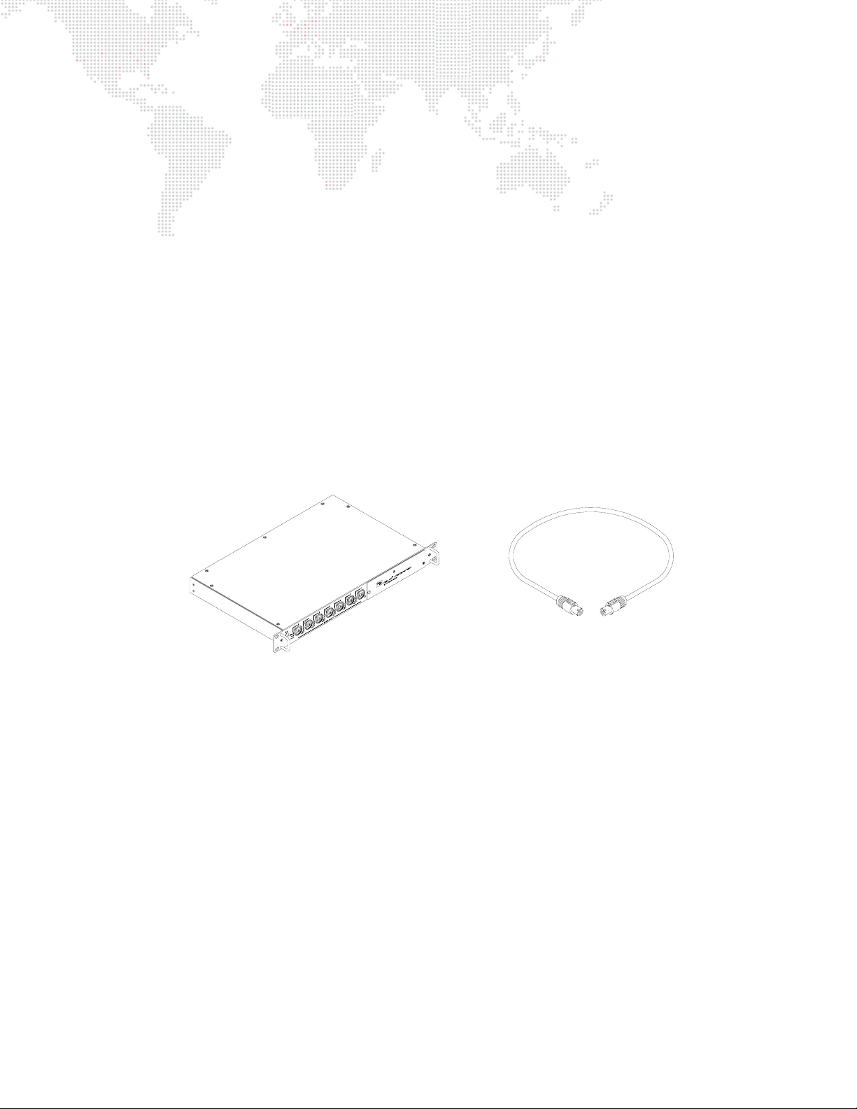
Included Items
The following illustration shows all items included with this model:
Note
: Copper connections are limited to a maximum distance of 300 feet.
AC Line Cord 208V
PRG Series 400 7-Port
Ethernet Switch (20.9801.0200.07)
PowerCon® Cable Assembly
(25.9801.0214)
Figure 4: 7-Port Ethernet Switch Included Items
PRG SERIES 400® ETHERNET SWITCH USER MANUAL 5
Page 8
Controls and Indicators
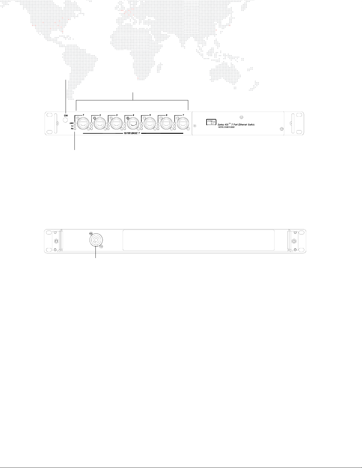
The Series 400 7-Port Ethernet Switch contains the following connections and LED indicators.
DC Power Indicator -
indicates AC power is applied.
10/100 Base T Connections -
input/output ports for standard signals.
Ethernet LEDs -
indicates valid Ethernet
link, transmit and receive
for each connection when lit.
Figure 5: 7-Port Ethernet Switch Front Panel
Neutrik Connector Allows connection of AC Line Cord 208V PowerCon Cable (supplied).
Figure 6: 7-Port Ethernet Switch Rear Panel
6 PRG SERIES 400® ETHERNET SWITCH USER MANUAL
Page 9
INSTALLATION
Installing Ethernet Switch
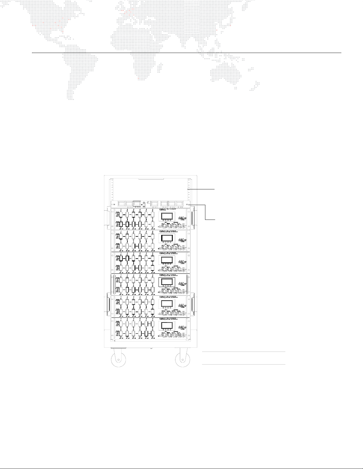
A Series 400 Ethernet Switch can be used independently or installed directly in a Series 400 rack chassis, using any
blank space above the LED Meter Module.
To install in Series 400 rack:
Step 1. Install Ethernet Switch as required in top portion of rack chassis (Figure 7).
Step 2. At Ethernet Switch rear panel, connect AC Line Cord 208V PowerCon® Cable (supplied) to Neutrik®
connector.
Step 3. After power is applied, verify that ON indicator is lit.
Step 4. At front panel, connect data cables as required. Refer to "Connecting Ethernet Switch to System" on
page 8.
SERIES 400 RACK CHASSIS
3U of rack space for
adding additional signal
processing devices.
EXAMPLE CONFIGURATION
S400 Rack Components May Vary
Figure 7: Series 400 Rack
LED Meter Module
PRG SERIES 400® ETHERNET SWITCH USER MANUAL 7
Page 10
Connecting Ethernet Switch to System
The Series 400 10-Port Ethernet Switch connects Ethernet devices using
both
CAT5e copper wire
and
armored fiber
optic cable. Copper wire communication ports conform to 10/100Base-Tx standards and the fiber ports conform to
10/100Base-Fx standards. The Series 400 7-Port Ethernet Switch connects Ethernet devices using
only
CAT5e
copper wire.
AC Input
SERIES 400 ETHERNET SWITCH
Fiber Optic Out to Additional Switches
Fiber Optic
10/100Base-T
10/100Base-T
10/100Base-T
10/100Base-T
10/100Base-T
10/100Base-T
10/100Base-T
Fiber Optic
Input from
a Virtuoso/V676 Console
or another switch
Virtuoso Nodes
Any Ethernet Device
or
(up to 7)
Input from
a Virtuoso/V676 Console
or another switch
10-Port Model Only
Figure 8: Device Connection Diagram
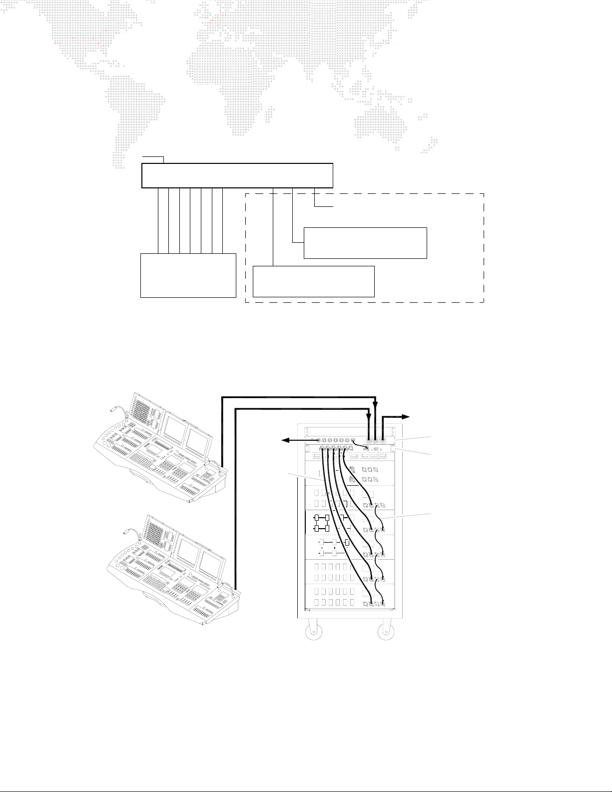
The following example system diagrams illustrate an Ethernet Switch being used with a Series 400 Power and Data
Distribution Rack.
VIRTOUSO CONSOLE A
VIRTOUSO CONSOLE B
FIBER OPTIC CABLE
FIBER OPTIC CABLE
TO OTHER
DEVICES
DMX UNIVERSE
CABLES
A
ABA
BB
A
B
SERIES 400 RACK
TO OTHER
SWITCHES
PRG S-400 10-PORT
ETHERNET SWITCH
VIRTUOSO NODE
CAT5e CABLES
* Fiber optic connections available only with the 10-Port Ethernet Switch model.
Figure 9: Sample System Connection Diagram 1
8 PRG SERIES 400® ETHERNET SWITCH USER MANUAL
Page 11
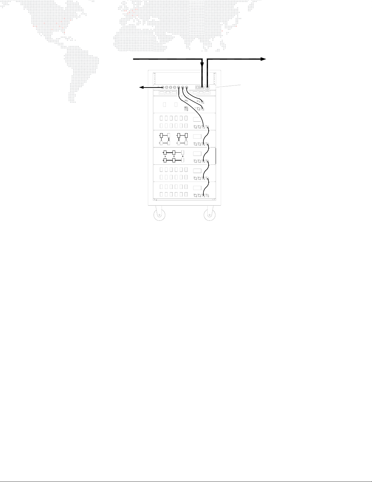
FIBER OPTIC CABLE
FROM REMOTE RACKS
FIBER OPTIC CABLE
TO REMOTE RACKS
CAT5e CABLE TO
LOCAL RACKS
* Fiber optic connections available only with the 10-Port Ethernet Switch model.
A
B
A
A
B
B
A
B
SERIES 400 RACK
PRG S-400 10-PORT
ETHERNET SWITCH
A
B
Figure 10: Sample System Connection Diagram 2
PRG SERIES 400® ETHERNET SWITCH USER MANUAL 9
Page 12
SPECIFICATIONS
Technical Specifications
POWER REQUIREMENT: 90 to 264 VAC, 47 to 63 Hz
Draws less than 60 watts continuously.
COOLING: Convection.
OPERATING TEMP: -20°C to 50°C (-4°F to 122°F)
COPPER PORTS: Seven isolated copper ports that can accept Ethernet signals using either 10Base-T or
100Base-TX standards. Automatic detection and configuration of input signal speed.
FIBER OPTIC PORTS: (
10-Port model only
) Three fiber optic ports that can accept 100Base-FX Ethernet signal.
The speed and direction of these ports are fixed. The ports use 62.5/125um multi-mode
fiber media at 1300nm wavelength and operate up to a 2KM distance.
INDICATORS: Green LED power indicator to show that DC power has been applied.
Status LEDs for each port indicating Link, TX Data, and RX Data.
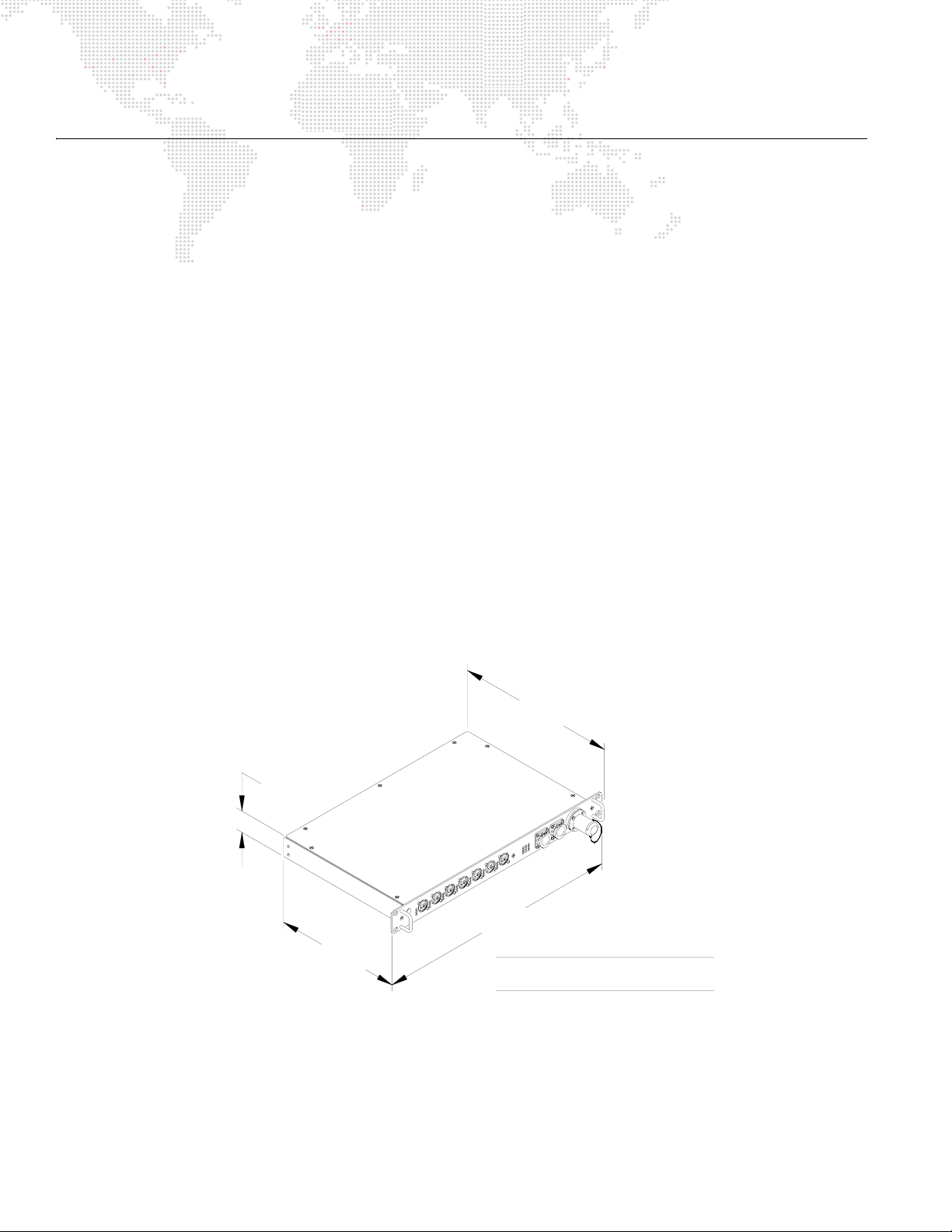
HOUSING: Standard 1U 19" rack mount chassis.
WEIGHT: 4.5 lbs (2.04 kg)
COMPLIANCE: United States: ANSI/UL 60950-1-UL Standard for Safety for Information Technology
Equipment Safety
Canada: CAN/CSA C22.2 No. 60950-1 Information Technology Equipment Safety
Europe: CE Mark
12"
(305 mm)
1.72"
(44 mm)
11"
(279 mm)
10 PRG SERIES 400® ETHERNET SWITCH USER MANUAL
19"
(483 mm)
10-Port Model Shown
All models have the same dimensions
Page 13

PRG Series 400® Ethernet Switch User Manual
Version as of: October 18, 2010
PRG part number: 02.9801.0001 B
Page 14

Production Resource Group
Dallas Office
8617 Ambassador Row, Suite 120
Dallas, Texas 75247
www.prg.com
 Loading...