

Page 1

SOFTWARE VERSION 2.1
WWW.PRG.COM
BEST BOY® HP SPOT LUMINAIRE
USER MANUAL
Page 2

AutoPar®, Bad Boy®, Best Boy®, Followspot Controller™, Mbox®, Mini Node™, Nocturne®, Series 400®, ReNEW®, Super Node™,
V476®, V676®, and Virtuoso® are trademarks of Production Resource Group, LLC, registered in the U.S. and other countries.
All other brand names which may be mentioned in this manual are trademarks or registered trademarks of their respective companies.
This manual is for informational use only and is subject to change without notice. Please check www.prg.com for the latest version.
PRG assumes no responsibility or liability for any claims resulting from errors or inaccuracies that may appear in this manual.
Best Boy® HP Spot Luminaire User Manual
Version as of: March 25, 2015
PRG part number: 02.9817.0001
Production Resource Group, LLC
Dallas Office
8617 Ambassador Row, Suite 120
Dallas, Texas 75247
www.prg.com
©2015 Production Resource Group, LLC. All Rights Reserved.
Best Boy® HP Spot Luminaire User Manual
Page 3
FOREWORD
Compliance Notice
This device complies with Part 15 of the FCC rules. Operation is subject to the following two conditions: 1) This device
may not cause harmful interference, and 2) This device must accept any interference received, including interference
that may cause undesired operation.
Conforms to:
UL STD 1573
Certified to:
CAN/CSA STD E598-1
CAN/CSA STD E598-2-17
Safety Notice
It is extremely important to read ALL safety information and instructions provided in this manual and any
accompanying documentation before installing and operating the products described herein. Heed all cautions and
warnings during installation and use of this product.
Safety symbols used throughout this manual are as follows:
CAUTION advising of potential damage to product.
WARNING advising of potential injury or death to persons.
GENERAL INFORMATION PERTAINING TO PROTECTION AGAINST ELECTRICAL SHOCK, FIRE, EXPOSURE TO
EXCESSIVE UV RADIATION, AND INJURY TO PERSONS CAN BE FOUND BELOW.
WARNING: INSTRUCTIONS FOR CONTINUED PROTECTION AGAINST FIRE
1) PRG luminaires have been designed for use only with specific lamps. Note lamp type before replacing. Installing
another type of lamp may be hazardous.
2) PRG luminaires may be mounted on any type of surface as long as mounting instructions are followed. See
instructions detailed in this manual.
3) Replace fuses with same type and rating only.
4) Minimum distance from head to any flammable object is 2m.
WARNING: INSTRUCTIONS FOR CONTINUED PROTECTION AGAINST ELECTRICAL SHOCK
1) PRG luminaires are designed for dry locations only. Exposure to rain or moisture may damage luminaire.
2) Disconnect power before servicing any PRG equipment.
3) Servicing to be performed by qualified personnel only.
WARNING: INSTRUCTIONS FOR CONTINUED PROTECTION AGAINST EXPOSURE TO EXCESSIVE
ULTRAVIOLET RADIATION
1) PRG luminaires may use an HID type lamp which produces UV radiation. DO NOT look directly at lamp.
2) It is hazardous to operate luminaires without complete lamp enclosure in place or when lens is damaged.
Lenses or UV shields shall be changed if they have become visibly damaged to such an extent that their
effectiveness is impaired.
BEST BOY® HP SPOT LUMINAIRE USER MANUAL I
Page 4

WARNING: INSTRUCTIONS FOR PROTECTION AGAINST INJURY TO PERSONS
1) Exterior surfaces of the luminaire will be hot during operation. Use appropriate safety equipment (gloves, eye
protection, etc.) when handling and adjusting hot equipment and components. Service and maintenance should
be performed only by qualified personnel as determined by the high pressure lighting fixture manufacturer.
2) Arc lamps generate intense heat. Disconnect power and allow lamp to cool for 5 minutes before relamping.
3) Arc lamps emit ultraviolet radiation which can cause serious skin burn and eye inflammation. Additionally, arc
lamps operate under high pressure at very high temperatures. Should the lamp break, there can exist a danger
of personal injury and/or fire from broken lamp particles being discharged.
4) The lamp shall be changed if it has become damaged or thermally deformed.
5) If lamp is touched with bare hands, clean lamp with denatured alcohol and wipe with lint-free cloth before
installing or powering up the luminaire.
6) Serious injury may result from the generation of ozone by this lamp system. A proper means of venting must be
provided.
II BEST BOY® HP SPOT LUMINAIRE USER MANUAL
Page 5
Notes de sécurité
Avant de procéder à l’installation des produits décrits dans ce guide et de les mettre en marche, il est extrêmement
important de lire TOUS les renseignements et TOUTES les directives de sécurité contenues dans ce guide ainsi que
toute documentation jointe. Tenir compte de tous les avertissements et suivre toutes les précautions pendant
l’installation et l’utilisation de cet appareil.
Les symboles de sécurité utilisés dans ce guide sont les suivants :
ATTENTION Ce symbole annonce que l’appareil risque d’être endommagé.
AVERTISSEMENT Ce symbole annonce qu’il y a risque d’accident grave ou même fatal.
CETTE SECTION CONTIENT DES INFORMATIONS GÉNÉRALES POUR SE PROTÉGER CONTRE LES DÉCHARGES
ÉLECTRIQUES, LES INCENDIES, L’EXPOSITION EXCESSIVE AUX RAYONS UV ET TOUT AUTRE ACCIDENT
POUVANT ENTRAÎNER DES BLESSURES.
AVERTISSEMENT: RISQUE D’ EXPLOSION.
1) Le service et le maintenance ne devront être assurés que par des personnes qualifiées comme precisé par le
frabricant des lampes à haute pression.
2) Des vêtement de protection et les procédures précisées dans le manuel du frabricant doit être fournies.
AVERTISSEMENT: RÉGLAGE DES LAMPES
1) Chaleur intense. Débrancher le matériel et laisser refroidir pendant 5 minutes avant de rallumer.
2) Risque l’incendie. N’utilise que des Philips MSR Gold™ FastFit Lamp.
AVERTISSEMENT: DIRECTIVES POUR SE PROTÉGER CONTRE UNE EXPOSITION EXCESSIVE AUX RAYONS
UV
1) Risque d’explosion en cas de radiation ultraviolet imprantes.
2) Ne pas intervener en l’absence de confinement de la lampe en place ou quand la lentille est abîmée.
AVERTISSEMENT: DIRECTIVES POUR SE PROTÉGER CONTRE LES ACCIDENTS POUVANT ENTRAÎNER DES
BLESSURES
1) Chaleur intense. Eviter tout contact avec des personnes ou des tissues. Attention, de graves blessures
peuvent résulter de production d’ozone par cette lampe. Un système de ventilation adapté doit être fournies
2) La température de surface = 300.c
La temperature de l’ambiance = 50.c
3) Ne convient pas pour un usage résidential.
4) Utilisable seulement dans les locaux secs.
BEST BOY® HP SPOT LUMINAIRE USER MANUAL III
Page 6

Revision History
This manual has been revised as follows:
Version Release Date Notes
BASIC March 25, 2015 Initial release.
IV BEST BOY® HP SPOT LUMINAIRE USER MANUAL
Page 7

TABLE OF CONTENTS
Introduction
About This Manual........................................................................................................................................................................ 1
Additional Documentation ............................................................................................................................................................ 1
Training Videos ............................................................................................................................................................................. 1
Customer Service ......................................................................................................................................................................... 2
Gobo Art Submission Guidelines ................................................................................................................................................. 2
Chapter 1. Description
Features
Overview....................................................................................................................................................................................... 4
Components
Included Items .............................................................................................................................................................................. 5
Replacement Items and Accessories ........................................................................................................................................... 5
Major Components and Controls ................................................................................................................................................. 6
Designer Color Wheel Standard Configuration ............................................................................................................................ 7
Effect Wheel Standard Configuration ........................................................................................................................................... 7
Gobo Wheel Standard Configurations ......................................................................................................................................... 8
About Moiré Gobos............................................................................................................................................................... 8
Chapter 2. Installation
Power and Data Cabling Requirements
Power ......................................................................................................................................................................................... 10
Data ............................................................................................................................................................................................ 10
DMX512 Cables .................................................................................................................................................................. 10
DMX512 Male Termination Connector ................................................................................................................................ 12
Ethernet Cables................................................................................................................................................................... 12
Ethernet Bypass .................................................................................................................................................................. 12
Installation Procedures
Unpacking and Attaching Hanging Brackets ............................................................................................................................. 13
Standard Hang ........................................................................................................................................................................... 15
Vertical "Yoke Out" Hang............................................................................................................................................................ 17
Standing Position ....................................................................................................................................................................... 19
Light Shield................................................................................................................................................................................. 20
Connecting Power and Data ...................................................................................................................................................... 21
Power Up and Basic Setup Procedures
Powering Up the Luminaire ........................................................................................................................................................ 23
Comm LED Operation ......................................................................................................................................................... 24
Bypassing Calibration................................................................................................................................................................. 24
Setting a Starting Address.......................................................................................................................................................... 25
DMX Comm......................................................................................................................................................................... 25
Ethernet Comm ................................................................................................................................................................... 26
Starting the Lamp ....................................................................................................................................................................... 27
Configuring Comm Loss Setting ................................................................................................................................................ 28
Configuring Universe, Comm, and Other Options ..................................................................................................................... 28
Chapter 3. Operation
Menu System
Using the Menu Touchscreen ..................................................................................................................................................... 30
Wake Switch............................................................................................................................................................................... 30
Menu System Overview.............................................................................................................................................................. 31
Home Screen.............................................................................................................................................................................. 32
Lamp Screen .............................................................................................................................................................................. 33
BEST BOY® HP SPOT LUMINAIRE USER MANUAL V
Page 8

Configuration Screen .................................................................................................................................................................. 33
Pan/Tilt Screen .................................................................................................................................................................... 34
Communication Screen .............................................................................................................................................................. 34
Status Screen ............................................................................................................................................................................. 35
Information Screen ..................................................................................................................................................................... 35
Test Screen ................................................................................................................................................................................. 35
Test Sub-Menu Screens...................................................................................................................................................... 36
Followspot Control ..................................................................................................................................................................... 37
DMX512 Operation
DMX Channel Mapping............................................................................................................................................................... 39
Special Notes.............................................................................................................................................................................. 47
Timing Channels ......................................................................................................................................................................... 48
Channel Functions............................................................................................................................................................... 48
Timing Channel Mapping .................................................................................................................................................... 48
Gobo Set Zero Position .............................................................................................................................................................. 52
Chapter 4. Troubleshooting and Maintenance
Troubleshooting
Troubleshooting Guide................................................................................................................................................................ 54
Errors .......................................................................................................................................................................................... 55
Status Indications................................................................................................................................................................ 55
Comm LED .......................................................................................................................................................................... 55
Te st i ng
Test Screen ................................................................................................................................................................................. 58
Mechanical Tests ........................................................................................................................................................................ 60
Group Tests ................................................................................................................................................................................ 61
Software Update
Software Update Using LumLoader Application ........................................................................................................................ 62
Software Crossload .................................................................................................................................................................... 63
Equipment Handling
Proper Lamp Servicing and Operation ....................................................................................................................................... 64
Routine Maintenance
Replacing the Lamp.................................................................................................................................................................... 65
Adjusting Lamp........................................................................................................................................................................... 67
Removing Head Covers.............................................................................................................................................................. 69
Cleaning the Luminaire Exterior.................................................................................................................................................. 70
Cleaning the Lenses ................................................................................................................................................................... 71
Cleaning Gobo, Color, and Effect Wheels .................................................................................................................................. 74
Replacing a Gobo in Gobo Wheel 1 ........................................................................................................................................... 75
Replacing a Gobo in Gobo Wheel 2 ........................................................................................................................................... 77
Replacing a Designer Color Filter ............................................................................................................................................... 79
Appendix A. Technical Specifications
Best Boy HP Spot Luminaire ...................................................................................................................................................... 82
Best Boy Road Case .................................................................................................................................................................. 84
Appendix B. Glossary
Glossary of Terms ....................................................................................................................................................................... 86
VI BEST BOY® HP SPOT LUMINAIRE USER MANUAL
Page 9
INTRODUCTION
About This Manual
This manual provides necessary information regarding product safety, installation, and operation for the following
equipment:
+ Best Boy® HP Spot Luminaire
Familiarizing yourself with this information will help you get the most out of your lighting system.
WARNING: It is important to read ALL accompanying safety and installation instructions to avoid damage to
the product and potential injury to yourself or others.
Additional Documentation
For more information about DMX512 and sACN protocols, refer to the following documents available from the
American National Standards Institute (ANSI) at www.ansi.org:
+ ANSI E1.11 - 2008 (R2013)
Entertainment Technology - USITT DMX512-A, Asynchronous Serial Digital Data Transmission Standard for
Controlling Lighting Equipment and Accessories
+ ANSI E1.31 - 2009
Entertainment Technology – Lightweight streaming protocol for transport of DMX512 using ACN
+ ANSI E1.20 - 2010
Entertainment Technology-RDM-Remote Device Management over USITT DMX512 Networks
The above documents are also available for free in electronic format at tsp.plasa.org
For more information about Art-Net, refer to the following document available from Artistic Licence Engineering at
www.artisticlicence.com:
+ Specification for the Art-Net Ethernet Protocol
Training Videos
Best Boy Training Videos are available on the PRG website. For a list of videos, refer to the following webpage:
+ http://www.prg.com/best-boy-training-videos/
BEST BOY® HP SPOT LUMINAIRE USER MANUAL 1
Page 10

Customer Service
For technical assistance, contact the PRG International Service Center or contact your nearest PRG office. Contact
information for all PRG office locations can be found on our website at: www.prg.com
PRG Dallas (International Service)
8617 Ambassador Row, Suite 120
Dallas, Texas 75247 USA
Phone: 214.630.1963
Fax: 214.630.5867
Service Fax: 214.638.2125
Service Email: [email protected]
For Best Boy support, please contact: [email protected]
For additional resources and documentation, please visit our website at: www.prg.com
Gobo Art Submission Guidelines
1) Each black and white image should be submitted with artwork oriented as intended for viewing when projected
from the luminaire onto a flat surface such as a white wall.
2) Highest resolution and cleanest available image or sketch should be submitted - preferably in vector format
(Adobe Illustrator, AutoCad .dxf or .dwg, etc.) or, alternately, a raster image (.tiff, .jpeg, .bmp or .gif) may be used.
3) Areas of the image that are to be left open or clear should be shown in the artwork as white, while areas of the
image that are to be occluded or opaque should be shown in the artwork as black.
4) Orient image so that the intended top of the image is pointing straight up.
5) Colored images should be submitted in CMYK color space to accommodate the color separation process.
6) Artwork files should be emailed to: [email protected]
2 BEST BOY® HP SPOT LUMINAIRE USER MANUAL
Page 11

1.
DESCRIPTION
This chapter contains an overview of luminaire features and components.
FEATURES
+
+ COMPONENTS
Page 12
FEATURES
Overview
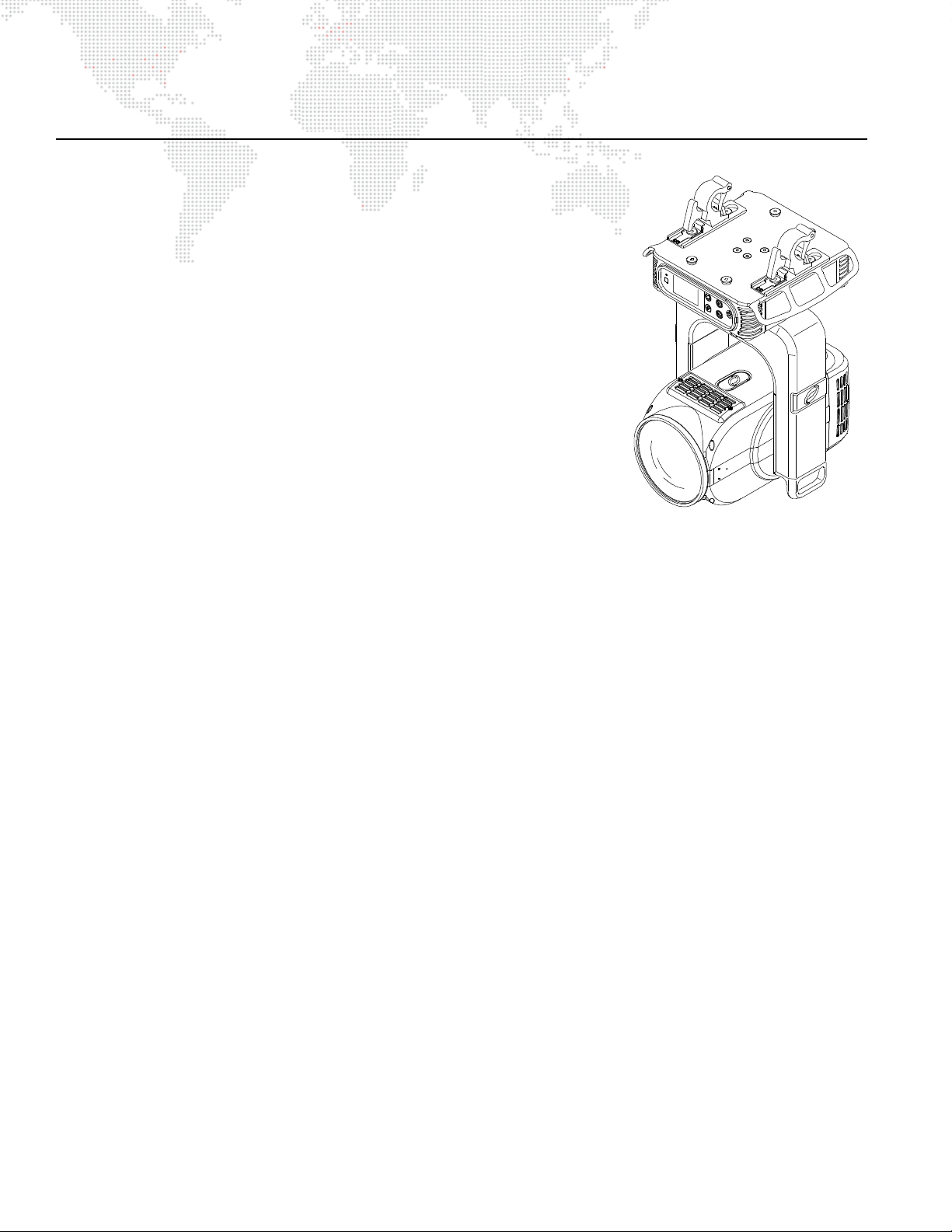
The Best Boy HP Spot Luminaire is a precision-engineered, automated fixture
with optics optimized for 20,000 lumens.
Features
+ SOURCE: HTI 1500W/D7/60 Lamp
+ OUTPUT: 31,000 lumens
+ POWER DRAW: Max. 10.5A at 208V, 8.75A at 240V. Auto-sensing voltage
input range is 200-240V, 50/60HZ
+ REFLECTOR: Precision glass reflector with cold mirror coating.
+ ZOOM RANGE: 8:1 from a tight spot of 8° to a very wide flood of 64°
maintaining focus throughout.
+ BEAM SIZE CONTROL: In addition to the zoom optics, a mechanical iris
provides continuous beam size control for both rapid changes and
smooth, timed beam angle changes.
+ FRAMING: Four-blade framing system featuring four independent blades
mounted in two planes. Each blade can be tilted +/- 30° and the entire
frame system can be rotated +/- 60° for a total travel of 120°.
+ DIMMING: Gray-scale glass dimmer for full-field dimming from 0% to 100% with accurate slow-speed control
and fast bumps.
+ STROBE: Servo-powered, lightning fast strobe wheel.
+ EFFECTS: One (1) multiplying four-facet prism, two (2) glass effects, and variable frost.
+ COLOR: CMY color system featuring three (3) crossfading color wheels of Cyan, Magenta, and Yellow, plus one
(1) designer wheel with seven (7) user-changeable color filters.
+ COLOR TEMPERATURE CONTROL: Adjustable color temperature wheel, range from 3,000K all the way up to
7,500K. Includes an integrated minus green filter.
+ ROTATING GOBOS: Two (2) indexable, rotating gobo wheels with six (6) gobos per wheel. Gobos are individually
calibrated so the unit will automatically index the orientation of each gobo regardless of initial placement. Both
gobo wheels accept PRG Moiré Gobos™ for advanced gobo rotator effects.
+ OPERATING TEMPERATURE: -20° to 120°F (-29° to 49°C)
+ CONTROL: Compatible with all PRG consoles and a wide variety of DMX512 and Art-Net consoles.
+ DMX CHANNELS: 45 DMX512 channels required per unit.
+ ETHERNET BYPASS: A relay allows Ethernet signals to pass through daisy-chained luminaires even if power is
removed.
+ ON-BOARD CONTROL: Built-in LCD touchscreen display allows for on-board fixture control and feedback. On-
board battery power allows for the fixture address and configurations to be set without having to apply AC power
to the luminaire.
+ PAN & TILT: Three-phase, high-speed servomotors. Brakes are applied when off.
+ RANGE: Pan - 615°, Tilt - 260°
+ POSITIONING: Can be mounted in any orientation.
+ SPACING: Hangs on 33 inch (838 mm) centers when Light Shield is extended. Hangs on 28 inch (711 mm) centers
when Light Shield is not extended.
+ WEIGHT: 106 lbs (48.08 kg) without hooks.
4 BEST BOY® HP SPOT LUMINAIRE USER MANUAL
Page 13
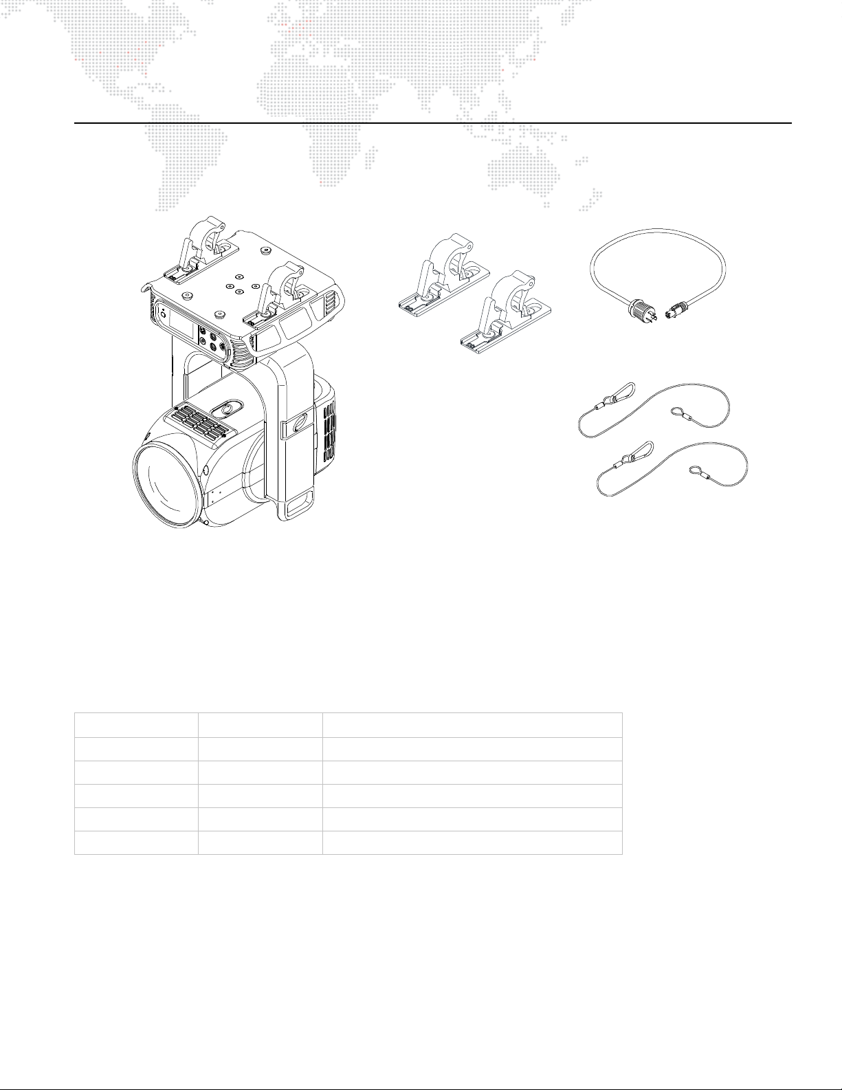
COMPONENTS
(2) Hanging Bracket Assemblies
(2) Safety Cables
AC Line Cord
-- with Mega-Claw Truss Hook
Power Cable
21.9816.0863
25.9812.0902.5
22.9816.0033
Best Boy HP Luminaire
20.981 7.0001
2.3749D
2.3749A-75
Included Items
The following illustration shows all items included with the luminaire:
Figure 1-1: Best Boy HP Luminaire Included Items
Replacement Items and Accessories
The following items can be ordered from PRG.
PRG P/N TEAM Ecode Accessory
21.9816.0863 - Hanging Bracket Assembly
22.9816.0033 2.3749A-75 Heavy Duty Safety Cable
23.9623.0177 - DMX Termination Connector
25.9812.0902.5 - AC Line Cord 2.5' 14/3 L6-20 Cable Assembly
71.2550.1500.0 2.3749D-11 HTI 1500W/D7/60 Lamp
BEST BOY® HP SPOT LUMINAIRE USER MANUAL 5
Page 14

Major Components and Controls
12AMax
50 /60 Hz
IN
DMX
THRU
ETHERNET
COMM
WAKE
BAD
-015
BST
-011
200 -240 VAC
ACIN
Neutrik® AC
DMX512 Input
DMX512 Thru
Upper Enclosure Detail
Upper Enclosure -
House s po w er su pp ly, ballas t , Ma s ter Contro l
Board (MCB), and provides Data In and Thru,
and AC power connections. Also houses the
Menu Touchscreen (see detail below).
Hanging Bracket Assembly (2) Allows l uminaire to be mou nted on truss pipe.
Yoke Assembly - Houses Yoke Driver
Contro l Board, and Pan & Tilt servos.
FRONT VIEW
Power Connector
Front Lens
Head Assembly -
Houses Color, Gobo, Effect, Zoom, Iris,
Frost, Dimmer, and Strobe mechanisms.
Ethernet Port
Ethernet Port
Menu Touchscreen Used to configu re luminaire address
and other options. Also, provid es
status information and testing.
Comm LED
Battery Wake Switch
Light Shield Blocks light spill.
The following illustration shows the external luminaire components and controls.
Figure 1-2: Best Boy HP Luminaire External Components and Controls
6 BEST BOY® HP SPOT LUMINAIRE USER MANUAL
Page 15
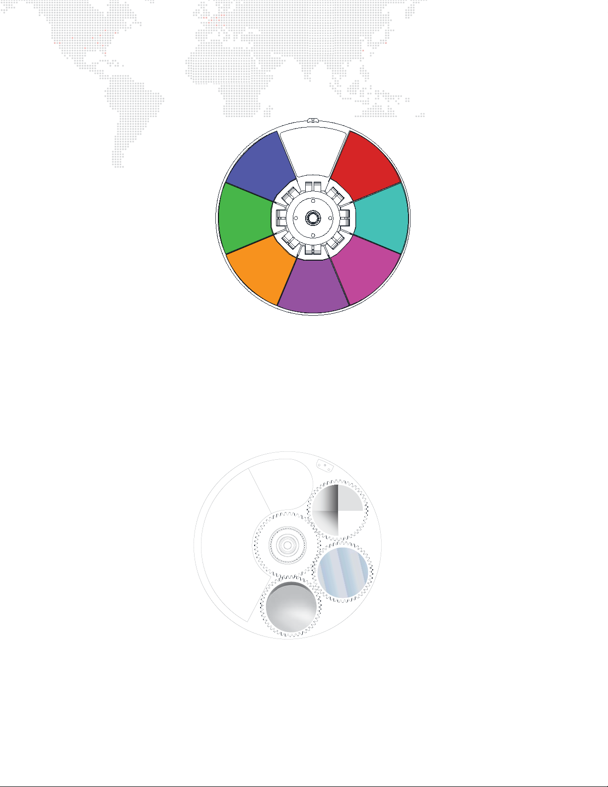
Designer Color Wheel Standard Configuration
The following drawing shows the standard Designer Color Wheel configuration.
POSITION #7
UV BLUE
(22.9816.0324.07)
POSITION #6
REAL GREEN
(22.9816.0324.06)
POSITION #5
ORANGE
(22.9816.0324.05)
Figure 1-3: Designer Color Wheel Standard Configuration
Effect Wheel Standard Configuration
OPEN
POSITION #4
ROSY MAGENTA
(22.9816.0324.04)
POSITION #1
DEEP RED
(22.9816.0324.01)
POSITION #2
TURQUOISE
(22.9816.0324.02)
POSITION #3
FOLLIES PINK
(22.9816.0324.03)
The following drawing shows the standard Effect Wheel configuration.
OPEN
VARIABLE
DIFFUSION
POSITION #3
OBLONG
(22.9816.8003)
Figure 1-4: Effect Wheel Standard Configuration
POSITION #1
4-FACET PRISM
(22.9816.8001)
POSITION #2
EXTRUDER
(22.9816.8002)
BEST BOY® HP SPOT LUMINAIRE USER MANUAL 7
Page 16
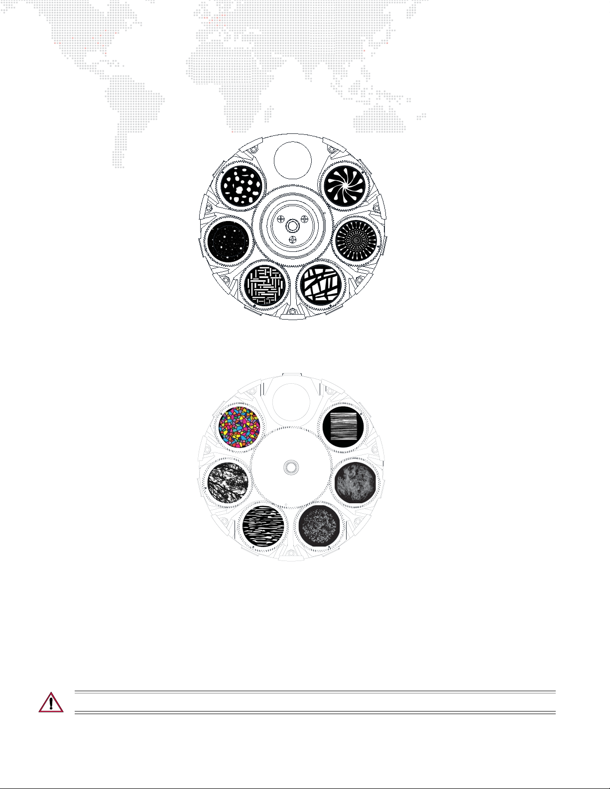
Gobo Wheel Standard Configurations
GOBO WHEEL 1
GOBO WHEEL 2
The following drawings show the standard Gobo Wheel configurations.
POSITION #1
JUST ROCKS
(17.1131.1007.01)
POSITION #2
PIN HOLE BREAKUP
(17.1131.1002.00)
POSITION #1
CHICLETS
(17.1131.5000.00)
POSITION #3
SLITS
(17.1131.1001.00)
OPEN
OPEN
POSITION #6
CLUBBED SPIRAL
(17.1131.1030.00)
POSITION #5
KALEIDOSCOPE MOIRÉ
(17.7101.0400.00)
POSITION #4
SLATE WALL 4
(17.1131.1006.01)
POSITION #6
STRAW 2
(17.1131.1022.03)
POSITION #2
OAK FOLIAGE 1
(17.1131.1010.00)
POSITION #3
CRACKLE LINEAR
(17.1131.1013.00)
POSITION #4
GHOST DUST
(17.1131.1022.04)
POSITION #5
FIREWATER ANIMATION
(17.7101.0401.00)
Figure 1-5: Gobo Wheel Standard Configurations
About Moiré Gobos
Moiré gobos contain two pieces of glass: one that is fixed and another that rotates. Since the two pieces of glass are
very close together, it creates an interesting interference effect (which is referred to as the "moiré"). Due to this
construction they do not contain sensors, and therefore cannot be calibrated to a certain orientation at startup as with
standard gobos.
CAUTION: Moiré gobo positions MUST be set using the menu system.
8 BEST BOY® HP SPOT LUMINAIRE USER MANUAL
Page 17

2.
INSTALLATION
This chapter contains instructions for installing the luminaire. It includes instructions for connecting
power and data, along with instructions for powering up the luminaire for the first time and addressing
it within your system.
POWER AND DATA CABLING REQUIREMENTS
+
+ INSTALLATION PROCEDURES
+ POWER UP AND BASIC SETUP PROCEDURES
Page 18
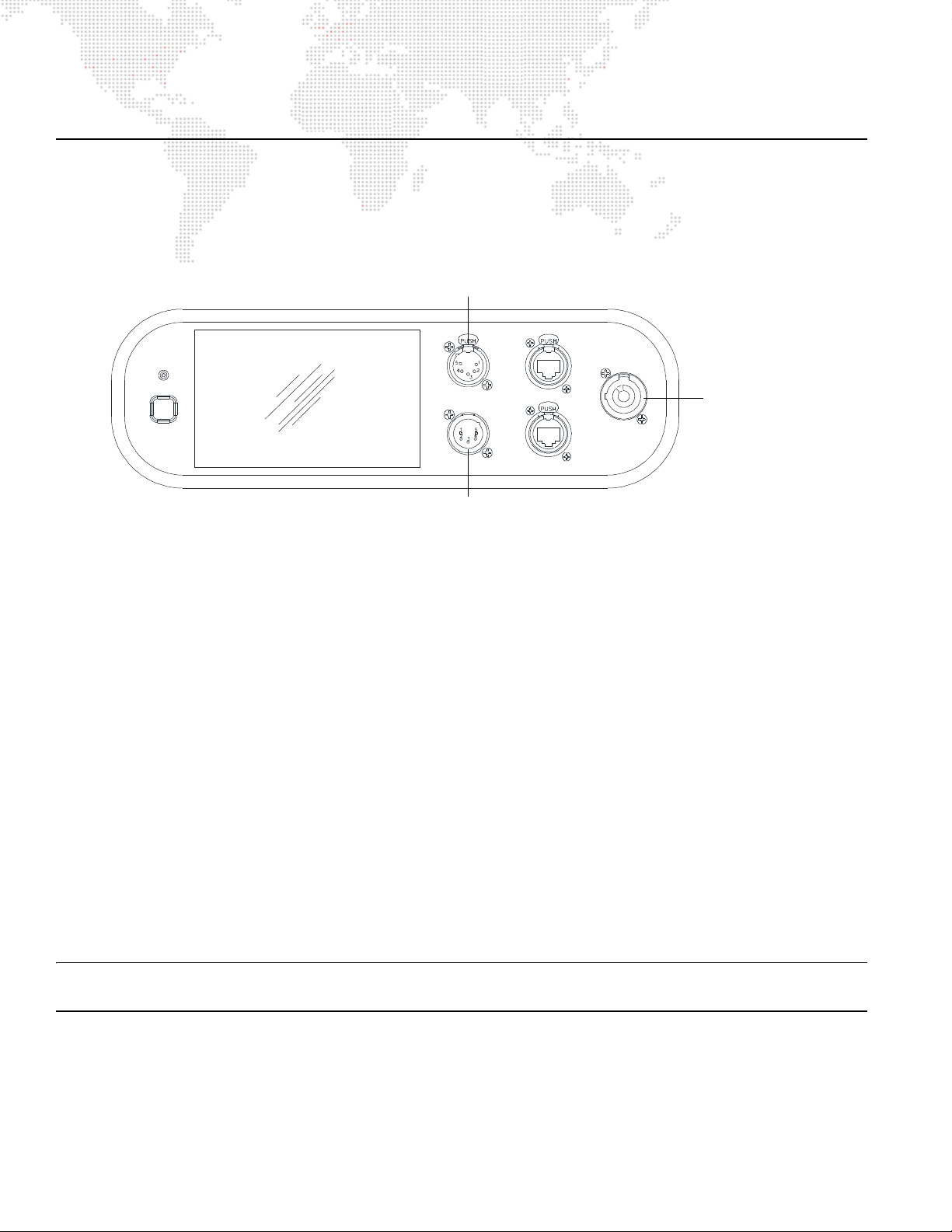
POWER AND DATA CABLING REQUIREMENTS
100 -240 VAC
12A Max
50 / 60 Hz
IN
DMX
THRU
ETHERNET
AC IN
COMM
WAKE
Neutrik® PowerCon
DMX512 Input
DMX512 Thru
AC Power Connector
Power
The Best Boy HP Spot Luminaire requires standard AC power distribution from 100-240 VAC, 50/60 Hz, 12A
maximum. The upper enclosure provides a Neutrik® PowerCon connector for power input. Use the provided AC Line
Cord Cable Assembly (25.9812.0902.5) to connect power.
Figure 2-1: Power Input and DMX512 Connections
Data
DMX512 Cables
The Best Boy HP Luminaire is equipped with two, 5-pin XLR connectors for DMX IN and DMX THRU (out)
applications. DMX IN requires a 5-pin, female XLR connector and DMX THRU requires a 5-pin, male XLR connector.
When purchasing or constructing data cables, it is important that not only the correct cable type be used, but also
quality cable to ensure a reliable DMX512 system. Your cabling should meet the following USITT DMX specification
requirements:
+ Suitable for use with EIA485 (RS485) operation at 250k baud.
+ Characteristic impedance 85-150 ohms, nominally 120 ohms.
+ Low capacitance.
+ Two twisted pairs.
+ Foil and braid shielded.
+ 24 AWG minimum gauge for runs up to 1000 feet (300m).
+ 22 AWG minimum gauge for runs up to 1640 feet (500m).
Note: Microphone type cables and other general purpose, two-core audio or signal cables are not suitable for use
with DMX512.
10 BEST BOY® HP SPOT LUMINAIRE USER MANUAL
Page 19
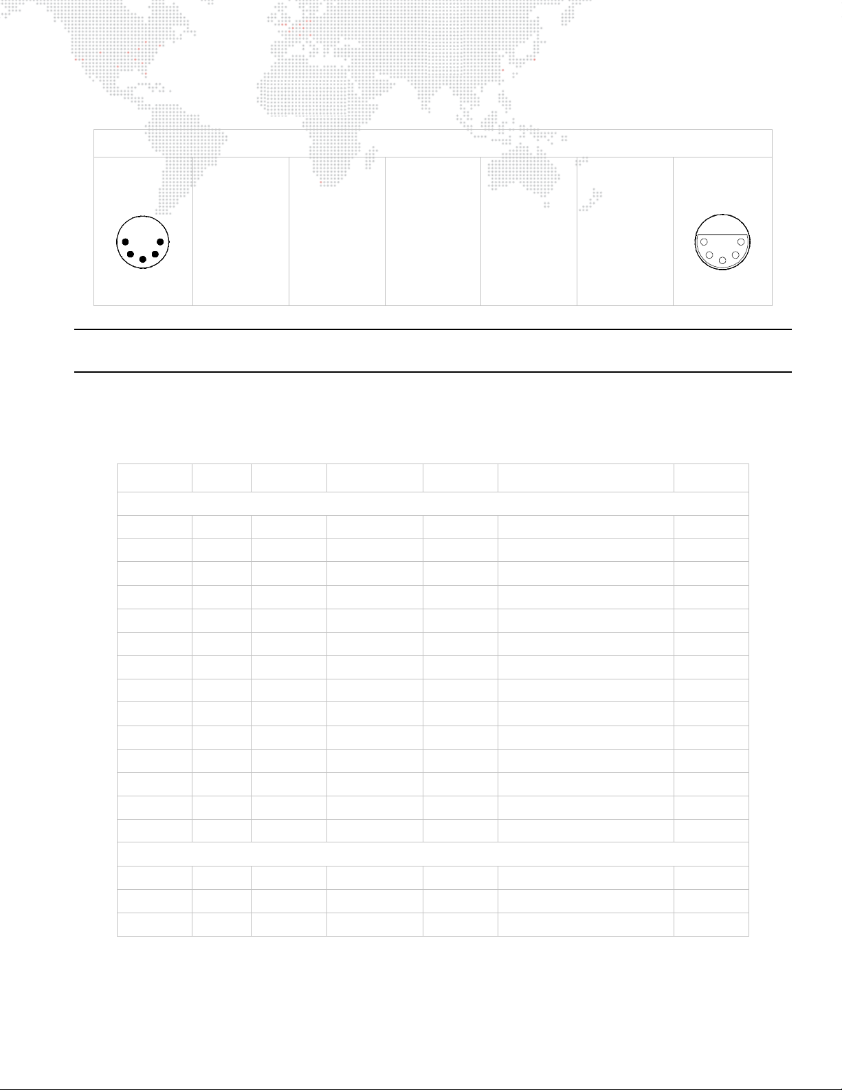
The XLR 5-pin connectors should be wired as follows:
1
2
3
4
5
1
2
3
4
5
Pin/Wire Code to XLR Connectors
DMX Thru
Cable Pinout
Male Conn
Pin 1
Foil & Braided
Shield
Pin 2
1st
conductor of
1st twisted
pair
Data (-)
Pin 3
2nd
conductor of
1st twisted
pair
Data (+)
Pin 4
1st
conductor of
2nd twisted
pair
Data (-)
Pin 5
2nd
conductor of
2nd twisted
pair
Data (+)
DMX In
Cable Pinout
Female Conn
Note: Refer to the USITT Recommended Practice for DMX512 guide for additional information regarding DMX512
systems. See "Additional Documentation" on page 1.
Recommended Cable Types/Manufacturers
These are only a few of the suitable cable types. Any quality EIA485, twisted pair, 120 ohm, shielded cable will also
work.
Ty pe P ai r s
1215A 2 150 PVC 26 IBM Type 6 Office cable 75
1269A 2 100 PTFE 22 (Solid) High Temp, Plenum cable 200
Z
Jacket AWG Use Temp (F)
Belden Cables
8102 2 100 PVC 24 UL2919 80
8132 2 120 PVC 28 UL2919 80
8162 2 100 PVC 24 UL2493 60
82729 2 100 PTFE 24 High Temp, Plenum cable 200
88102 2 100 PTFE 24 High Temp, Plenum cable 200
89696 2 100 PTFE 22 High Temp, Plenum cable 200
89729 2 100 PTFE 24 High Temp, Plenum cable 200
89855 2 100 PTFE 22 High Temp, Plenum cable 200
9729 2 100 PVC 24 UL2493 60
9804 2 100 PVC 28 UL2960 60
9829 2 100 PVC 24 UL2919 80
9842 2 120 PVC 24 UL2919 80
Proplex Cables
PC224P 2 110 Polyurethane 22 Heavy Duty and Portable 105
PC224T 2 110 PVC 22 UL2464 105
PC226T 3 110 PVC 22 UL2464
* Characteristic Impedance
BEST BOY® HP SPOT LUMINAIRE USER MANUAL 11
Page 20

DMX512 Male Termination Connector
Solder resistor
across pins 2 & 3
1
2
3
4
5
A male XLR DMX512 termination connector is required at the last luminaire (or "far end of
the line") to prevent signal reflections. Signal reflections may cancel out the signal at
certain line lengths, resulting in errors. The terminator is also necessary for software
downloads and running tests on multiple luminaires. To construct your own connector,
you will need the following components:
+ 5-pin, male XLR connector.
+ 120 ohm resistor.
Note: A male termination connector is also available as an accessory from PRG. See "Replacement Items and
Accessories" on page 5.
Ethernet Cables
The Best Boy HP Luminaire is equipped with two RJ-45 type connectors for Ethernet input/output. Ethernet cabling
should follow these guidelines:
+ Ethernet cable assemblies must match the CAT5e specification.
+ Regular or crossover cables are acceptable.
+ Both EtherCon® and RJ-45 connectors are acceptable.
Ethernet Bypass
A relay allows Ethernet signals to pass through daisy-chained luminaires even if power is removed.
12 BEST BOY® HP SPOT LUMINAIRE USER MANUAL
Page 21
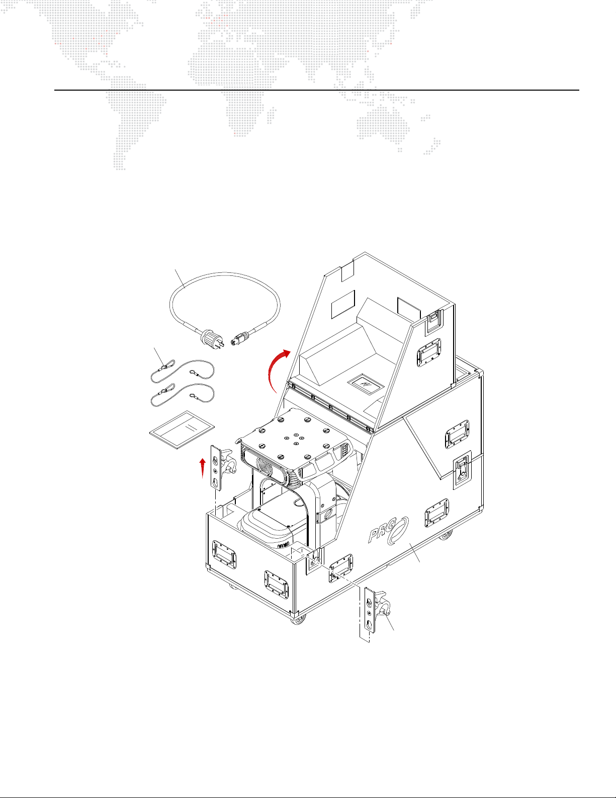
INSTALLATION PROCEDURES
Hanging Bracket (2)
Safety Cable (2)
Power Cord
Case
Unpacking and Attaching Hanging Brackets
The Best Boy HP Spot Luminaire can be hung horizontally or vertically from any structure designed to accommodate
the load of this moving luminaire. Two provided Hanging Bracket Assemblies (21.9816.0863) are used to attach the
luminaire to a truss pipe. The Hanging Brackets consist of a pre-assembled bracket with a Mega-Claw Truss Hook.
To unpack and attach brackets:
Step 1. Unlatch case lid and tilt upward as shown in Figure 2-2.
Step 2. Remove Power Cord, Safety Cables, and Hanging Brackets from case.
Figure 2-2: Unpacking Road Case
BEST BOY® HP SPOT LUMINAIRE USER MANUAL 13
Page 22
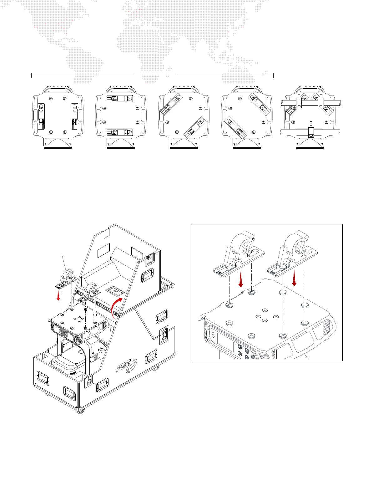
Step 3. Install Hanging Brackets as follows:
3-Point Hang *2-Point Hang
* Requires three brackets.
Hangin g B rac k et (2)
DETAIL
a. Choose orientation. Brackets may be attached in one of four positions as shown in Figure 2-3.
Figure 2-3: Hanging Bracket Orientations
b. Orient Hanging Bracket in desired direction over two attachment buttons on bottom of upper enclosure
(Figure 2-4).
c. Place Hanging Bracket down over buttons and slide until bracket locks into place (you will hear a "click"
when bracket is locked).
14 BEST BOY® HP SPOT LUMINAIRE USER MANUAL
Figure 2-4: Attaching Hanging Brackets
Page 23
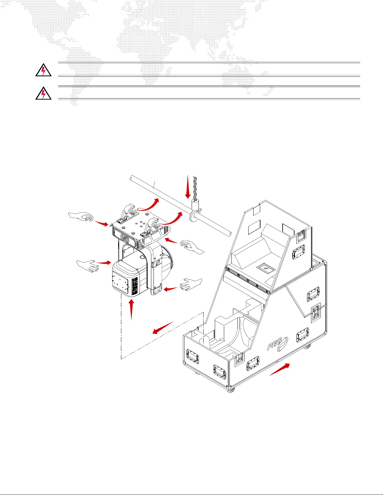
Standard Hang
Truss Pipe
WARNING: The luminaire is heavy. Use caution when lifting.
WARNING: Two safety cables and at least two truss hooks should be used in all hang configurations.
To install in standard 2-point hang:
Step 1. Unpack case and attach Hanging Brackets. Refer to "Unpacking and Attaching Hanging Brackets" on
page 13.
Step 2. Roll case to mounting location as required (Figure 2-5).
Step 3. Using two people, carefully lift luminaire into mounting position on truss pipe.
Figure 2-5: Removing Luminaire From Case
BEST BOY® HP SPOT LUMINAIRE USER MANUAL 15
Page 24
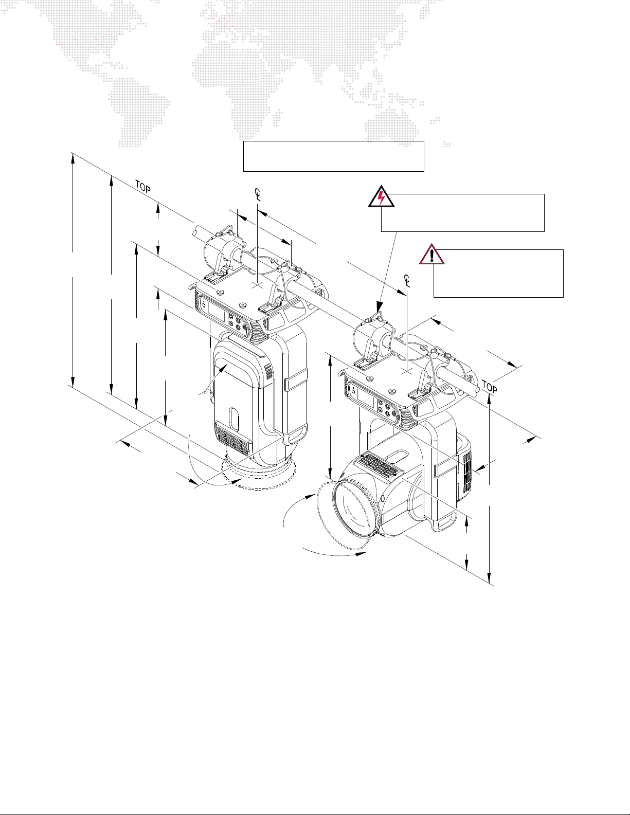
Step 4. Secure in place by tightening Truss Hook wing bolts (Figure 2-6). Ensure that luminaire is fully supported.
26.8"
(681 mm)
(711 mm)
28"
16.75"
(425 mm)
(290 mm)
11.4"
35.16"
(893 mm)
(991 mm)
39.0"
(147 mm)
5.78"
3.88"
(99 mm)
27.0"
(686 mm)
(574 mm)
22.6"
(473 mm)
18.64"
(486 mm)
19.15"
12.5"
(318 mm)
32.43"
(824 mm)
(724 mm)
28.5"
*(838 mm)
*33"
*31.6"
*(803 m m )
*(1054 m m )
*41.5"
*31.5"
*(800 mm)
Two (2) Safety Cables MUST be used
for all hanging installations and may
be required by local codes.
Safety cables and input
pigtail cable must be dressed
to avoid interference with
luminaire moti on.
NOTE: Mega-Claw Truss Hook is designed to
be used only with 2.0" OD round tubing.
* Dimensions with Light Shield extended.
POSITIONING:
Can be mounted in any orientation.
SPACING:
Hangs on 33 inch (838 mm) centers when
Light Shield is extended.
Hangs on 28 inch (711 mm) centers when
Light Shield is not extended.
WEIGHT:
109 lbs (49.44 kg) - without hooks
Step 5. Feed safety cables through base and secure around pipe as shown in Figure 2-6.
Step 6. Connect power and data cables according to "Connecting Power and Data" on page 21.
16 BEST BOY® HP SPOT LUMINAIRE USER MANUAL
Figure 2-6: Standard Hanging Configuration and Dimensions
Page 25
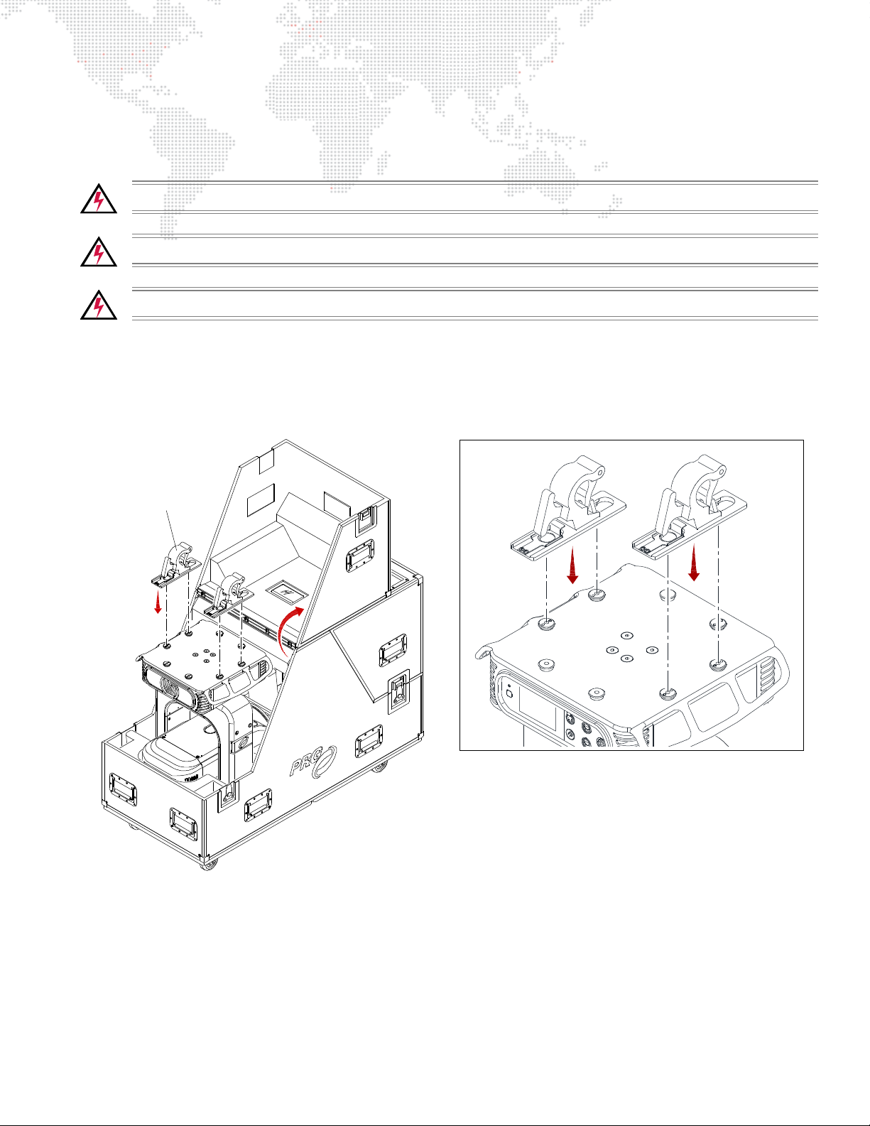
Vertical "Yoke Out" Hang
Hangin g B rac k et (2)
DETAIL
The Best Boy HP Spot Luminaire can be hung in a vertical position, if required. In this configuration, the luminaire
should be positioned so that the interface panel (display) is facing to the side for ease of programming.
WARNING: The luminaire is heavy. Use caution when lifting.
WARNING: The vertical configuration requires 3 people to hang and secure the luminaire.
WARNING: Two safety cables and at least two truss hooks must be used in all hang configurations.
To install in vertical hang:
Step 1. Orient Hanging Brackets as shown in Figure 2-7.
Step 2. Place Hanging Bracket down over buttons and slide until bracket locks into place (you will hear a "click"
when bracket is locked).
Figure 2-7: Attaching Hanging Brackets
BEST BOY® HP SPOT LUMINAIRE USER MANUAL 17
Page 26
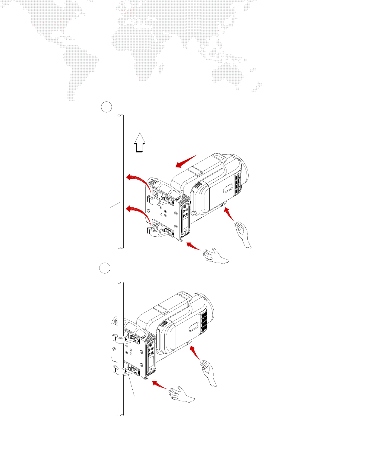
Step 3. Roll case to mounting location as required (Figure 2-8).
Remove Luminaire From Case
Attach to Vertical Truss
UP
Using a third person, secure in place
by tightening Tr uss Hook wing bolts.
Using tw o people, carefully lift luminaire
into mounting position as shown.
Wing Bolt (2)
1
2
Vertical
Truss
Step 4. Using two people, carefully lift luminaire into mounting position so that
display is facing to the side
.
Step 5. Using a third person, secure in place by tightening Truss Hook wing bolts. Ensure that luminaire is fully
supported.
Step 6. Feed safety cables through mounting bracket slots and secure around pipe.
Step 7. Connect power and data cables according to "Connecting Power and Data" on page 21.
Figure 2-8: Vertical "Yoke Out" Hanging Configuration
18 BEST BOY® HP SPOT LUMINAIRE USER MANUAL
Page 27
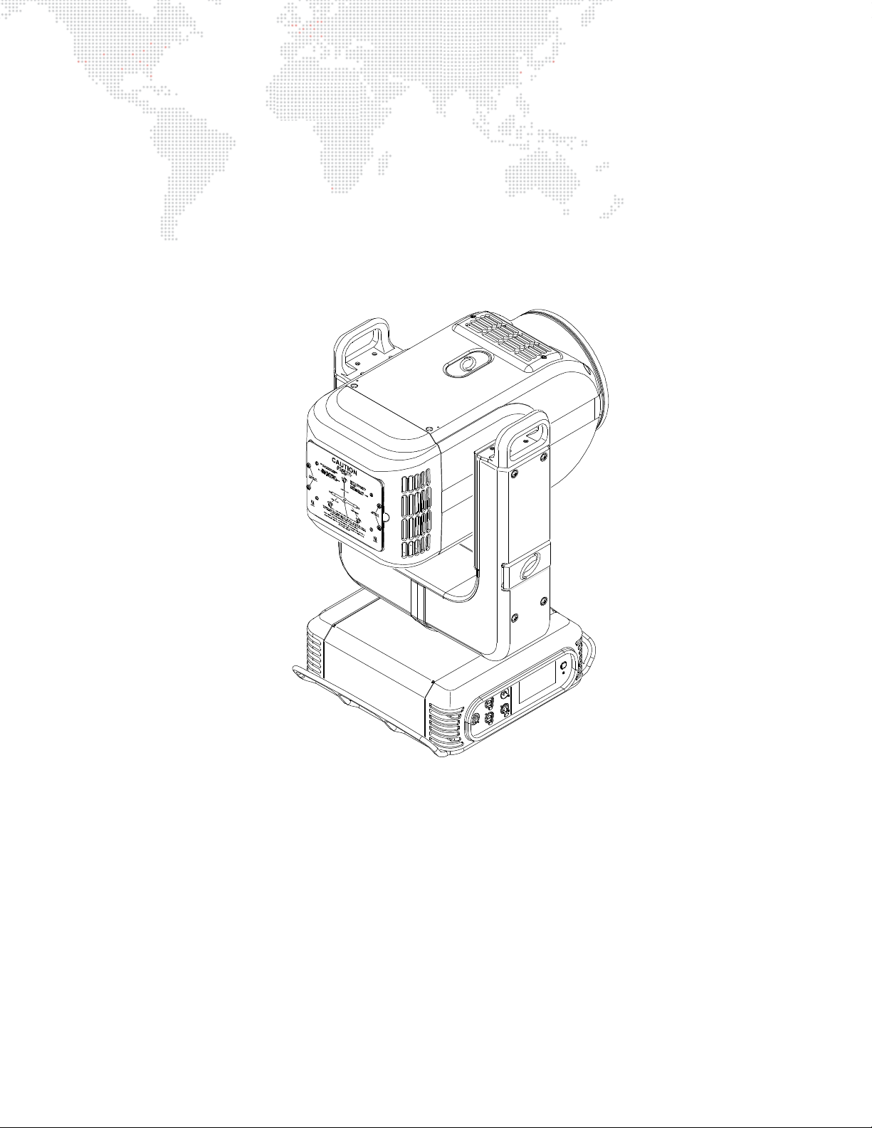
Standing Position
The Best Boy HP Spot Luminaire can also be used in a standing position. Be sure that the floor or stage will
accommodate the load of this moving luminaire.
To install in a standing position:
Step 1. Unpack case as shown in Figure 2-2 on page 13, but do not remove hanging brackets. (These are not used
for standing installations.)
Step 2. Carefully remove luminaire from case and place in standing position.
Step 3. Connect power and data cables according to "Connecting Power and Data" on page 21.
Figure 2-9: Standing Position
BEST BOY® HP SPOT LUMINAIRE USER MANUAL 19
Page 28
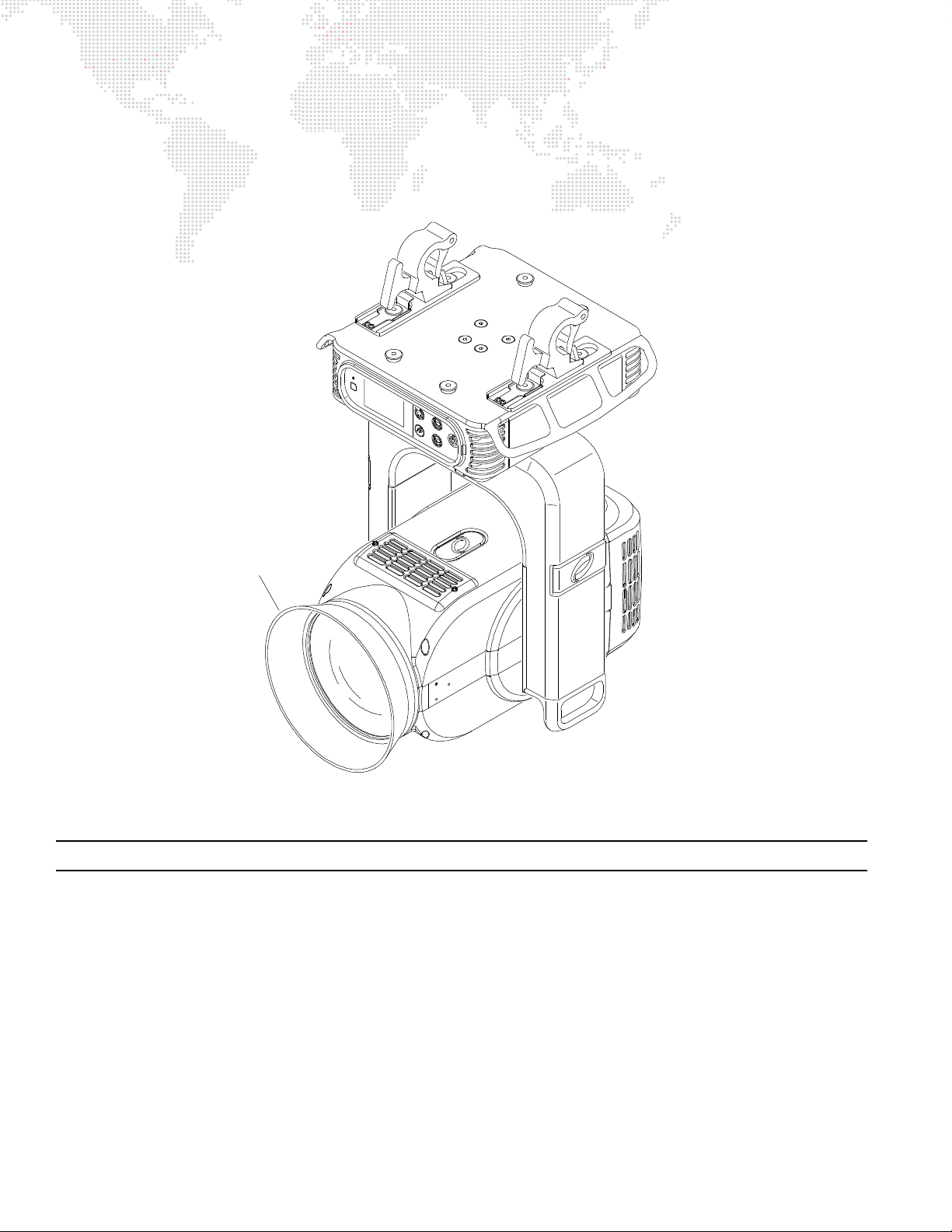
Light Shield
Light Shield
The Light Shield can be used to block light spill which may occur at some zoom angles.
To use the Light Shield, fold outward as shown below. If the Light Shield is not necessary, it can be folded backward.
Figure 2-10: Light Shield in Blocking Position
Note: When the Light Shield is extended, the luminaire spacing must be adjusted. Refer to Figure 2-6 on page 16.
20 BEST BOY® HP SPOT LUMINAIRE USER MANUAL
Page 29
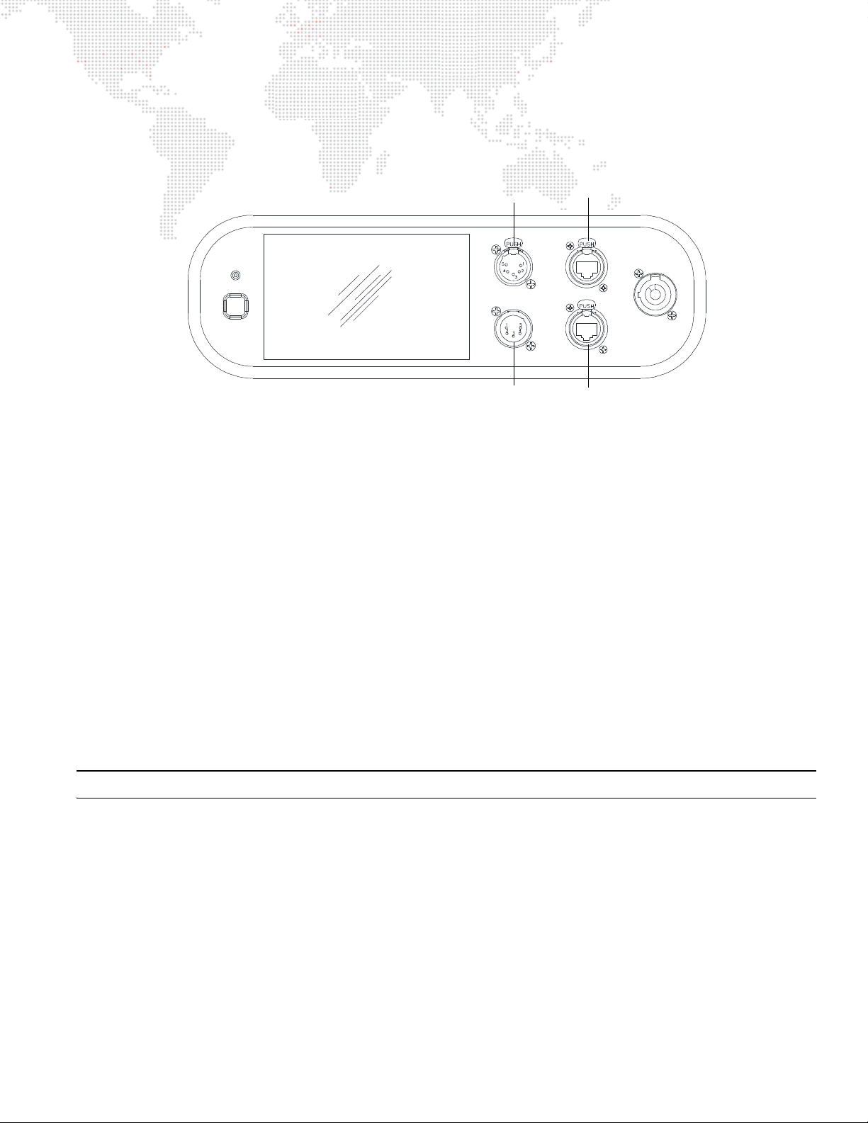
Connecting Power and Data
100 -240 VAC
12A Max
50 / 60 Hz
IN
DMX
THRU
ETHERNET
AC IN
COMM
WAKE
DMX512 Input
DMX512 Thru
Ethernet
Ethernet
The Best Boy HP Spot Luminaire may be controlled by DMX512 or Ethernet. The control inputs are located at the
upper enclosure connector panel.
Figure 2-11: Data Connections
Observe the following guidelines when setting up the system:
+ A maximum of 32 luminaires may be connected in any one DMX512 or Ethernet data link. However, note that the
maximum limit applies to the luminaire "daisy-chain" only. Your system or console may require fewer luminaires
on a single data link path. Consult your console documentation for more information.
+ The Ethernet ports are not assigned as either In or Thru as the DMX512 ports are assigned. Ethernet can be
connected in any configuration.
+ Standard "star" topology should be used with Ethernet configurations. DO NOT create a "ring" with Ethernet.
+ The ports may not be used as converters (i.e., you cannot input Art-Net and get DMX512 out on an XLR, or vice
versa).
+ A relay allows Ethernet signals to pass through daisy-chained luminaires even if power is removed.
Power is provided by the AC Line Cord Cable Assembly (25.9812.0902.5) connected to the Neutrik® power input
connector. There is no power on/off switch. Turn off the circuit breaker at the power distribution rack
connection or disconnecting the Neutrik PowerCon.
Note: Refer to "Comm LED Operation" on page 24 for more details about the Comm LED.
BEST BOY® HP SPOT LUMINAIRE USER MANUAL 21
before
Page 30
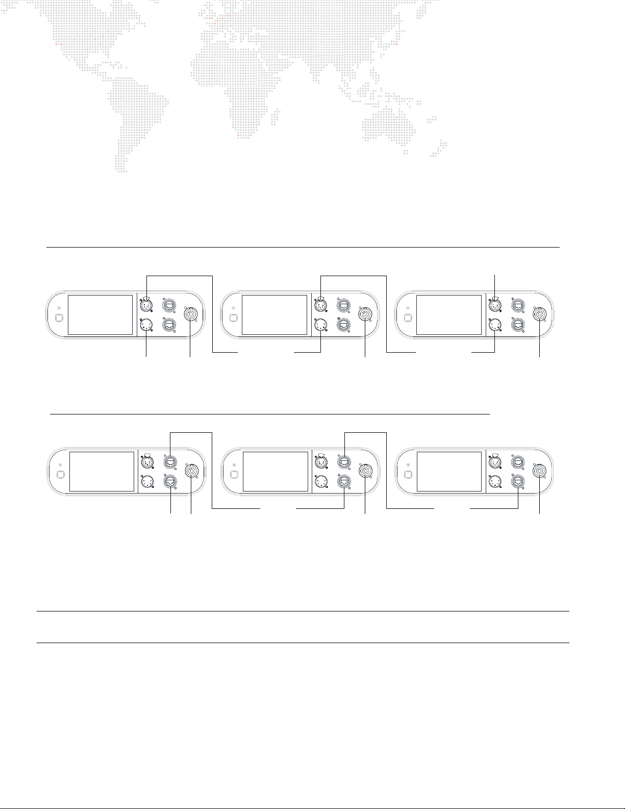
To connect power and data:
DMX512 In
Power In
Termination
Connector
DMX512 Daisy-Chain
Power In
Power In
DMX512 Thru
DMX512 Thru
Ethernet Daisy-Chain *
Power In Power In Power InEthern et In
Ethernet
Ethernet
Step 1. Connect data cable (DMX512 or Ethernet) from console to appropriate input connector at first luminaire in
chain (Figure 2-12).
Step 2. If required, connect additional data cables from appropriate thru connectors to input connectors of
remaining luminaires in chain.
Step 3.
For DMX512 systems
: At last luminaire in chain, install male termination connector at DMX512 THRU
connector. (Luminaires and other devices on the same DMX512 chain may not function properly without
termination.) Refer to "DMX512 Male Termination Connector" on page 12.
Step 4. At each luminaire, connect AC Line Cord Cable Assembly from power input source.
Step 5. Dress and secure all cables so that they will not interfere with luminaire head or yoke movement.
*The Ethernet ports are not assigned as either In or Thru as the DMX512 ports are. Ethernet can be connected in any configuration.
Note: If control data is active on both XLR and Ethernet connections, the fixture will follow the DMX512 commands
coming from the XLR.
22 BEST BOY® HP SPOT LUMINAIRE USER MANUAL
Figure 2-12: Connecting Power and Data Cables
Page 31
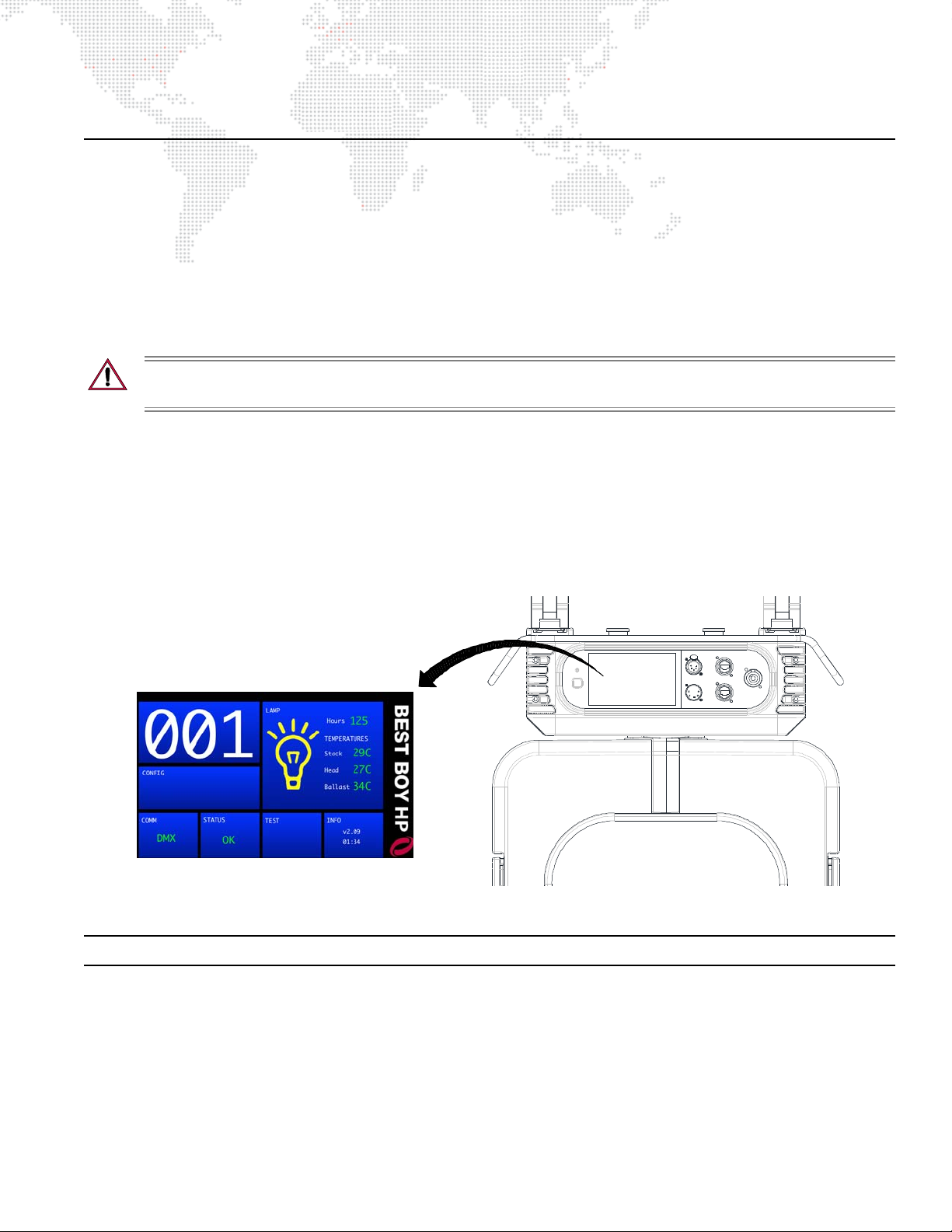
POWER UP AND BASIC SETUP PROCEDURES
Home Screen
Powering Up the Luminaire
When AC power is applied, the luminaire will begin a calibration sequence which moves its pan, tilt, and all beam
control mechanisms. After calibration, the luminaire head will either stop at its "home" position (which positions the
pan axis at mid-rotation and the head parallel to the yoke with the lens pointing away from the luminaire upper
enclosure) or move to its current DMX-defined position if DMX512 data is present. The beam control mechanisms will
also move to their "home" or DMX-defined positions. The lamp is set to OFF in the default mode.
The luminaire also contains an on-board battery so that it can be addressed and configured without being connected
to main power (refer to "Wake Switch" on page 30).
CAUTION: Before applying power, be sure the luminaire is hung or positioned so that the head and yoke can
move freely without restriction. Refer clearances in Figure 2-6 on page 16.
To power up:
Step 1. At each luminaire, connect power. Allow luminaire to complete its calibration sequence.
Step 2. For normal power up, the Menu Touchscreen "Home" screen will display Status OK. The Home screen will
also display the luminaire’s DMX address and lamp information.
Step 3. Check Comm LED for proper operation. Refer to "Comm LED Operation" on page 24.
Step 4. To strike lamp, send appropriate command from console or follow steps provided in "Starting the Lamp" on
page 27.
Figure 2-13: Menu Touchscreen at Power Up
Note: Refer to "Menu System" on page 30 for more information about the Menu Touchscreen.
BEST BOY® HP SPOT LUMINAIRE USER MANUAL 23
Page 32
Comm LED Operation
100 -240 VAC
12A Max
50 / 60 Hz
IN
DMX
THRU
ETHERNET
AC IN
COMM
WAKE
Comm LED
The Comm LED - located on the upper enclosure connector panel - indicates system control status. This can be used
determine if the luminaire is receiving a control signal. LED indications are as follows:
Figure 2-14: Comm LED
+ Green - The Comm LED will light
green
if either DMX or Ethernet control is present. Note that if both valid DMX
and Ethernet control are being received, DMX control will take precedence.
+ Red - The Comm LED will light red if no DMX or Ethernet is present, or if the incoming Ethernet control does not
include the fixture's selected universe.
+ Blink - The Comm LED will blink to indicate an error, regardless of the status of incoming comm.
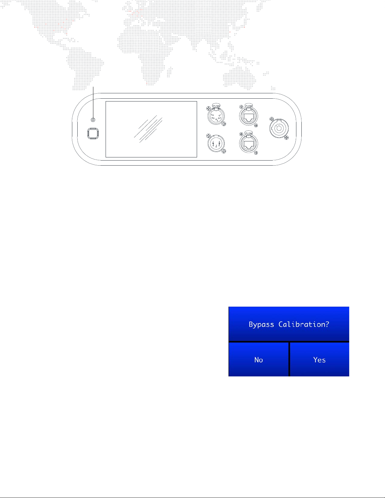
Bypassing Calibration
If the menu screen is touched (in the center) and held during startup, the luminaire will present a menu that provides
the option to bypass calibration. This feature allows the luminaire to skip the calibration sequence so that it can be
powered up in the case for configuration purposes.
To bypass calibration:
Step 1. Connect power to luminaire.
Step 2. At startup, touch center of menu screen and hold until
Bypass Calibration menu appears.
Step 3. Press Yes to bypass calibration. (The menu will
automatically dismiss if no selection is made within 5
seconds.)
Step 4. Proceed with programming of starting address or other
options.
24 BEST BOY® HP SPOT LUMINAIRE USER MANUAL
Page 33
Setting a Starting Address
Contr ol Input Type (DMX)
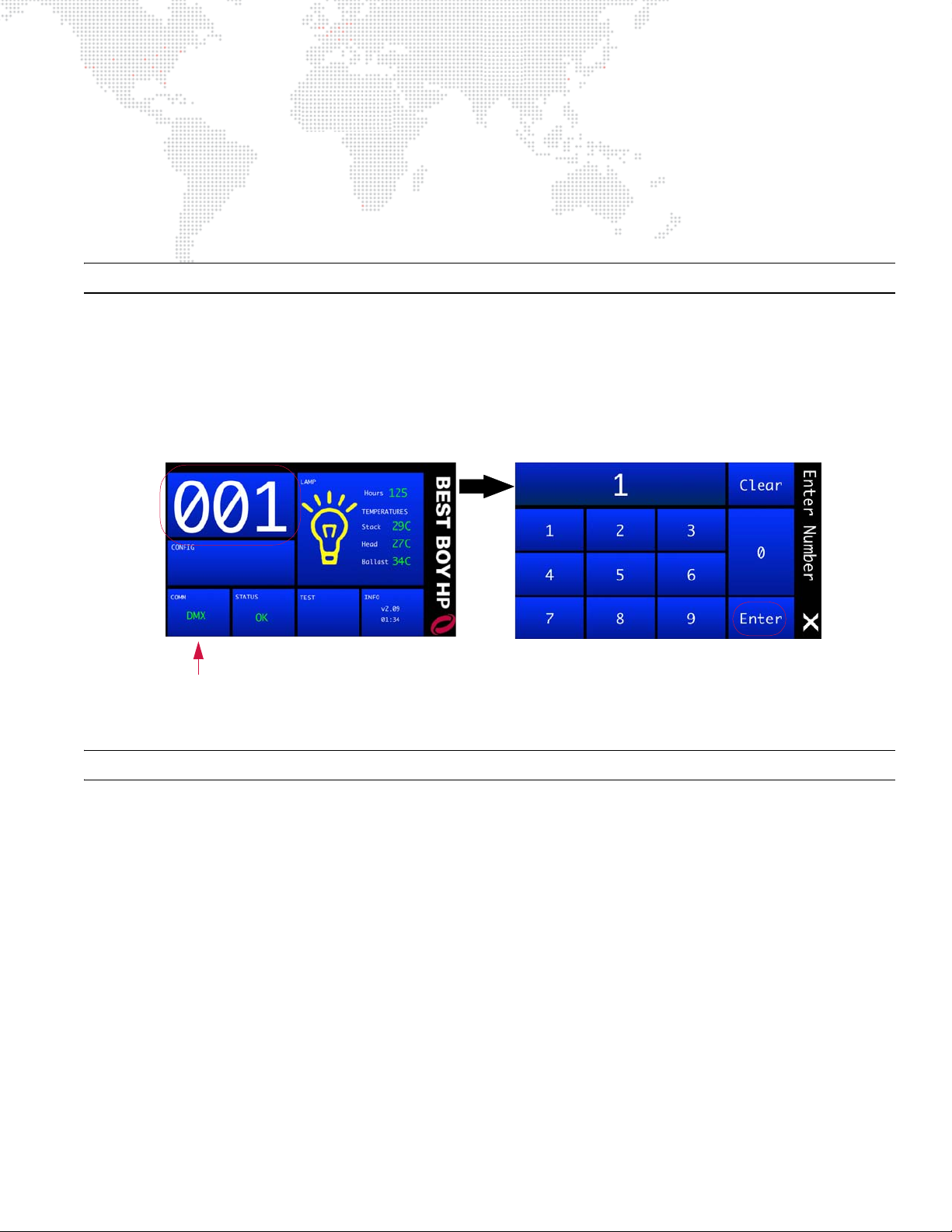
The method for setting a DMX starting address is the same whether the luminaire is being controlled by DMX512 or
Ethernet (Art-Net/sACN). The only difference is that the Home screen will display the Comm as either "DMX,"
"ArtNet," or "sACN," depending on the control input.
The DMX starting address is programmed at the Menu Touchscreen.
The luminaire retains its address even if power is
removed.
Note: Refer to your console operating instructions for specific information regarding its addressing requirements.
DMX Comm
The starting address for DMX512 systems can be set from the HOME screen.
To program a starting address:
Step 1. At Home screen, press address number panel.
Step 2. At numeric keypad, enter new starting address and press ENTER.
Figure 2-15: Setting Starting Address (DMX Control)
Note: Refer to "Menu System" on page 30 for more information about the Menu Touchscreen.
BEST BOY® HP SPOT LUMINAIRE USER MANUAL 25
Page 34
Ethernet Comm
Control Input Type (Ethernet)
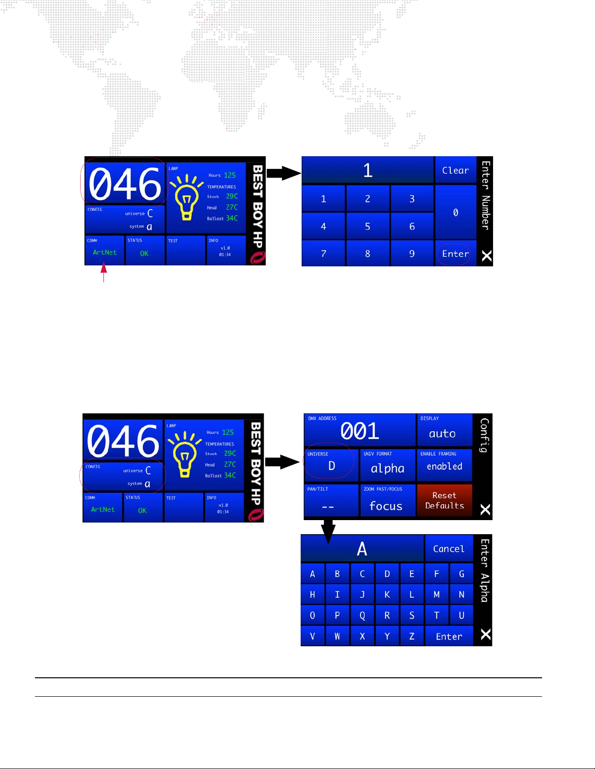
The starting address for Ethernet (Art-Net/sACN) systems can be set from the HOME screen.
To program a starting address:
Step 1. At Home screen, press address number panel.
Step 2. At numeric keypad, enter new starting address and press ENTER.
Figure 2-16: Setting Starting Address (Ethernet Control)
To select an Art-Net or sACN universe:
If using Ethernet control, a universe must be selected in addition to the DMX address. The universe can be selected
and displayed in either alphabetic or numeric mode (using the UNIV FORMAT screen). The alpha mode is useful to
differentiate universes from DMX addresses and is the standard on PRG console systems. The valid universes for ArtNet are 0-255 (A-IV), and the valid universes for sACN are 1-63999 (B-CPQN).
To set the Universe and Universe Format, press the CONFIG panel at the Home screen:
Figure 2-17: Selecting a Universe (Ethernet Control)
Note: Refer to "Menu System" on page 30 for more information about the Menu Touchscreen.
26 BEST BOY® HP SPOT LUMINAIRE USER MANUAL
Page 35
Starting the Lamp
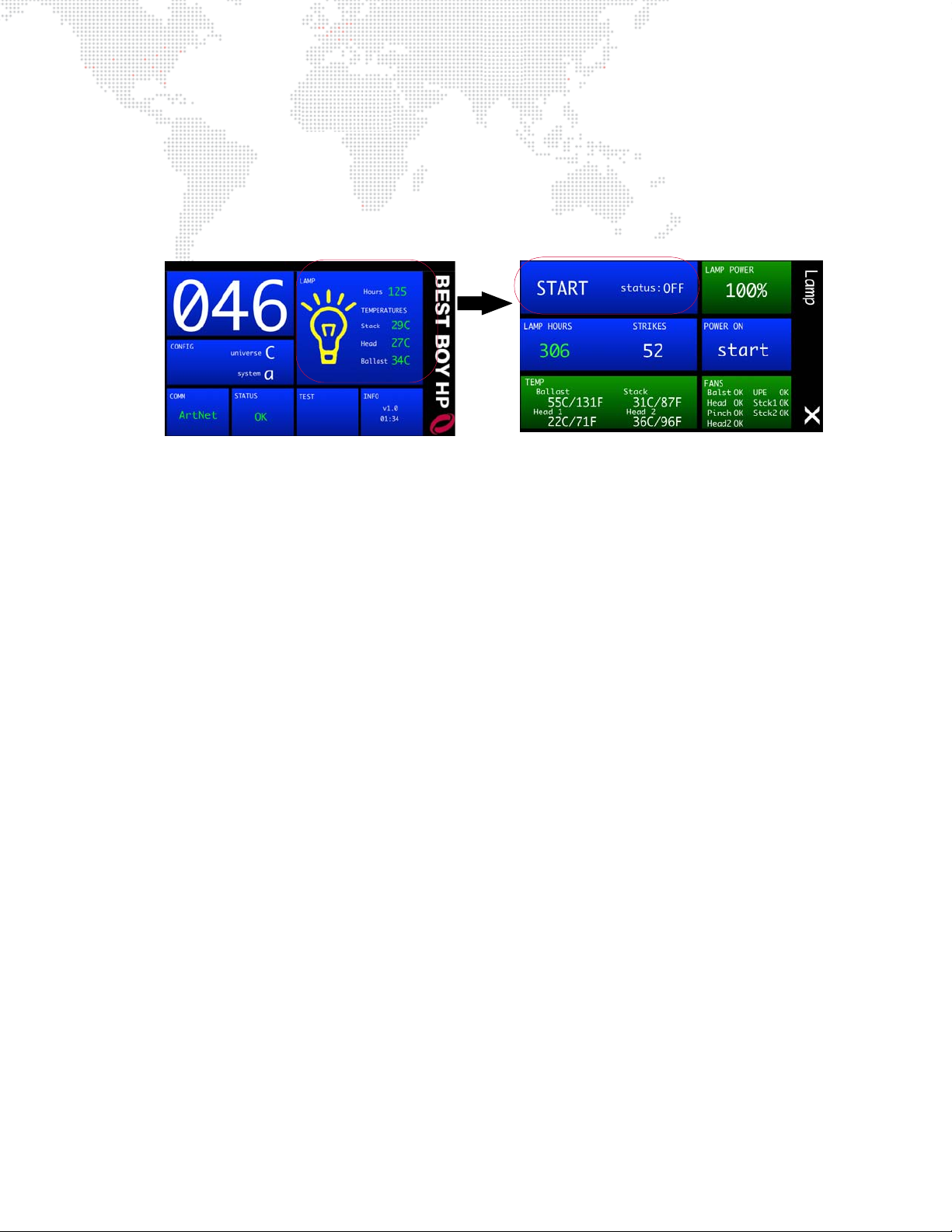
The lamp can be started (turned on) via console command or at the luminaire itself using the Menu Touchscreen.
To start lamp using Menu Touchscreen:
Step 1. At Home screen, press LAMP panel.
Step 2. At Lamp screen, current lamp status (ON/OFF) will be displayed. Press START to bring up YES/NO options.
Figure 2-18: Starting the Lamp
Step 3. Press YES to start lamp.
Step 4. Exit Lamp screen by pressing (X).
Lamp Power Up Setting
The luminaire can be configured to power up with its lamp on or off via the Lamp screen. For details about all lamp
configuration options, refer to "Lamp Screen" on page 33.
BEST BOY® HP SPOT LUMINAIRE USER MANUAL 27
Page 36
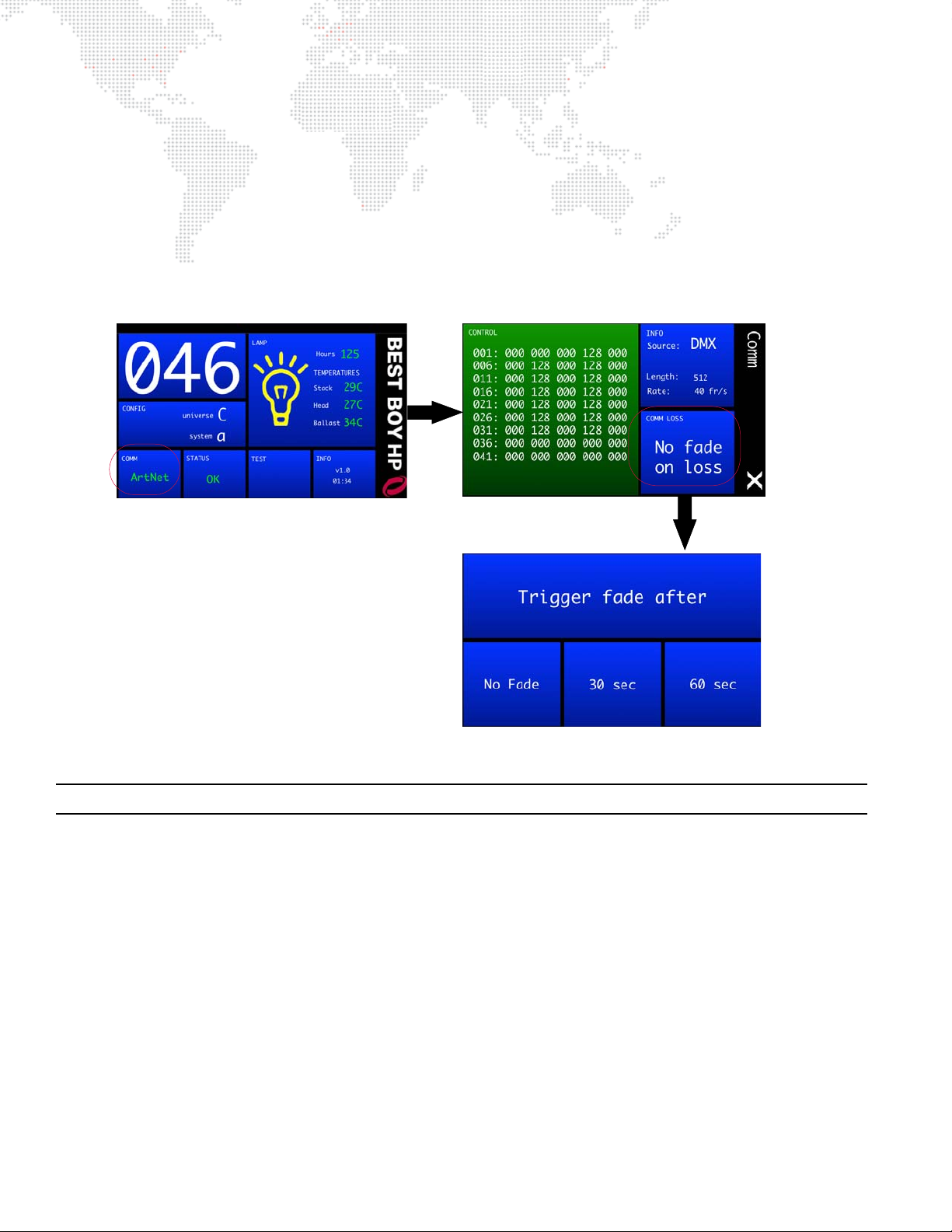
Configuring Comm Loss Setting
The Communication screen includes a "Comm Loss" setting. This setting will configure how long to wait before the
fixture fades to black upon loss of comm data.
To configure the Comm Loss setting:
Step 1. At Home screen, press COMM panel.
Step 2. At Communication screen, press COMM LOSS panel.
Step 3. Set Trigger Fade After to No Fade, 30 Seconds or 60 Seconds.
Step 4. Exit Communication screen by pressing (X).
Figure 2-19: Configuring Comm Loss Setting
Note: Comm Loss can also be configured with Control Channel commands. Refer to "Control Channels" on page 45.
Configuring Universe, Comm, and Other Options
Other luminaire configurations can be set using the menu screens available at the Menu Touchscreen. Refer to "Menu
System" on page 30 for complete instructions on using these features.
28 BEST BOY® HP SPOT LUMINAIRE USER MANUAL
Page 37

3.
OPERATION
This chapter contains instructions for using the menu system and controlling the luminaire by
DMX512.
MENU SYSTEM
+
+ DMX512 OPERATION
Page 38
MENU SYSTEM
100 -240 VAC
12A Max
50 / 60 Hz
IN
DMX
THRU
ETHERNET
AC IN
COMM
WAKE
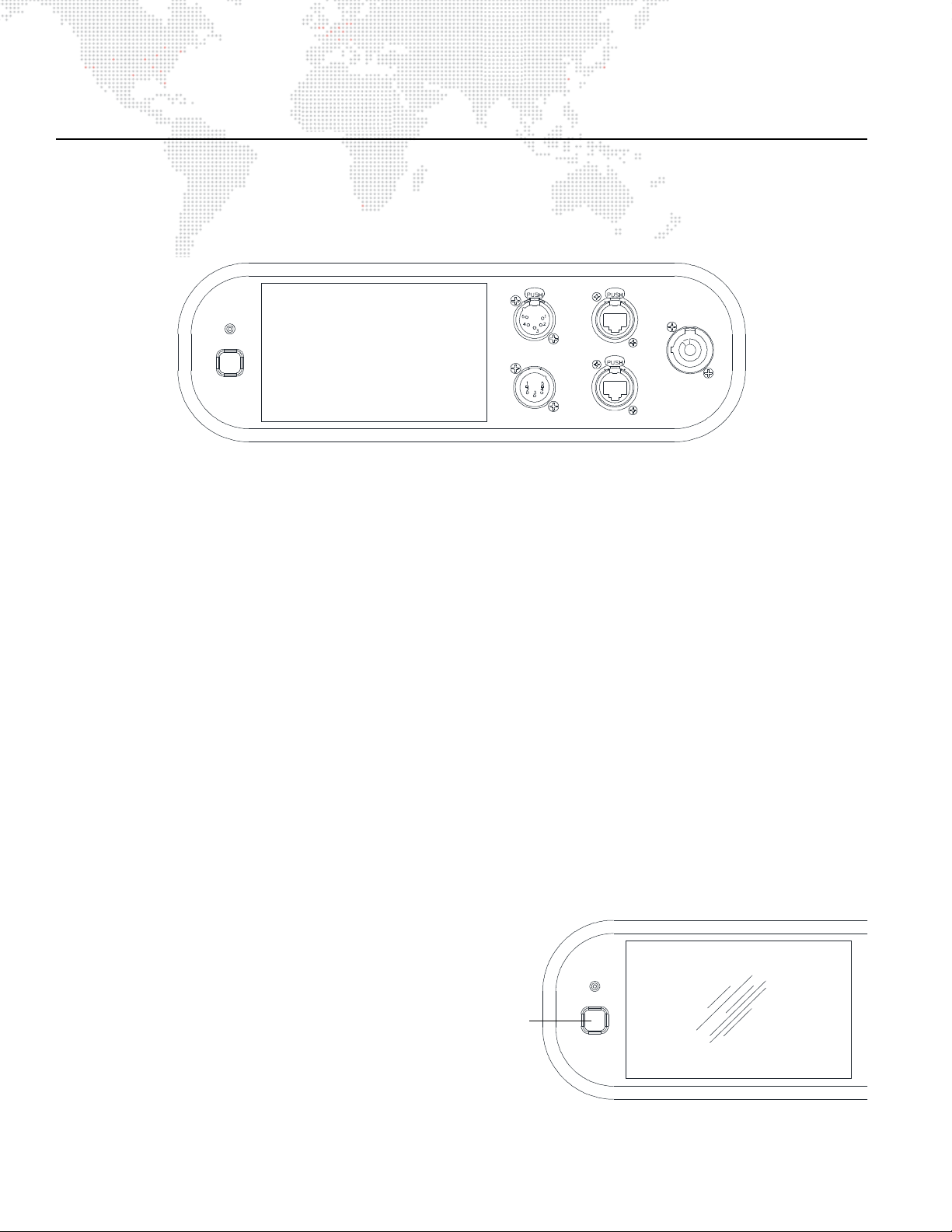
Menu Touchscreen -
Used to configure luminaire address
and other options. Also, provides
status information and testing.
COMM
WAKE
Wake Switch
Figure 3-2: Wake Switch
Using the Menu Touchscreen
The menu system is a set of software screens used to configure, address, report status, and test the luminaire. These
functions are controlled at the Menu Touchscreen as shown in Figure 3-1.
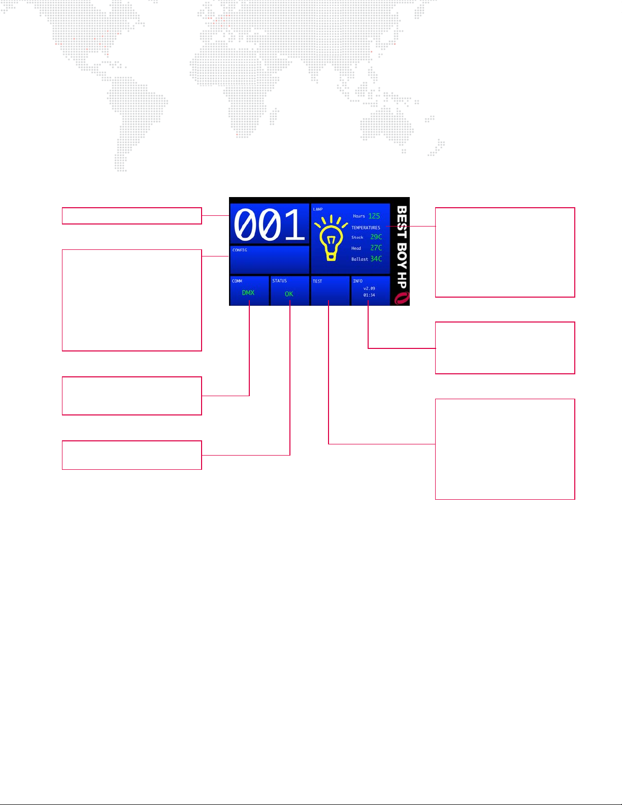
Figure 3-1: Menu Touchscreen
Color Codes
The menu panels are color coded as follows:
+ Blue - function control panels. These are configurable functions which will open a sub-menu when touched.
+ Green - informational panels. These display status info and will not open further menus when touched.
+ Red - important control panels. These are configurable functions which will open a sub-menu when touched.
Activating these functions will affect important luminaire settings.
Navigation
To navigate the menus, press the blue or red areas of the touchscreen.
Screen Saver Mode
The menu will automatically return to the Home screen, from a sub-menu, if inactive for 45 seconds. The display will
go into screen saver mode (backlight off) if inactive for five minutes.
The menu will automatically jump to the Status screen and wake up the display when a mechanism status changes
(error, calibration, etc.).
Bypass Calibration
If the menu screen is touched (in the center) and held during startup, the luminaire will present a menu that provides
the option to bypass calibration. This feature allows the luminaire to skip the calibration sequence so that it can be
powered up in the case for configuration purposes. (Refer to "Bypassing Calibration" on page 24.)
Wake Switch
The Best Boy HP Luminaire contains an on-board
battery so that it can be addressed and configured
without being connected to main power. A Battery
Wake Switch, located near the menu touchscreen,
can be used to access the menu system as required.
+ Press the switch once to bring up the power
down menu.
+ Press and hold the switch to force a power
30 BEST BOY® HP SPOT LUMINAIRE USER MANUAL
down.
Page 39
Menu System Overview
Lamp
- Start
- Lamp Powe r
- Lamp Hour s
- Strikes
- Power On
- Tempera tu re (T emp)
- Fans
Config (Configuration)
- DMX Address
- Display
- Universe
- Univers e Fo rm at
- Enable Fr am in g
- Pan/Tilt
- Zoom Fast /F oc us
- Reset Defaults
Status
- Mechanisms
- Log
Test
- Recalibrate
- Recalibrate ALL
- Disable
- Moiré Positions
- Mechanical Test
- Group Test
- Clean Lenses
- Fuse Map
Info (Information)
- Fixture Hours
- Run Time
- Softwar e Ver si on
- Crossload Software
Address
- DMX Address
Comm (Co mm un ication)
- Control
- Info
- Comm Loss
The menu system consists of a hierarchy of menu levels. Sub-menus, options, and alpha/numeric keypads may be
accessed by pressing the blue and red areas of these main screens. Pressing the right bar (X) while at a sub-menu will
return to the previous screen.
When power is applied to the luminaire, the Menu Touchscreen will display an initialization screen during calibration.
After calibration is complete, the Home screen will be displayed.
The main menu structure is illustrated below:
Figure 3-3: Menu Structure
BEST BOY® HP SPOT LUMINAIRE USER MANUAL 31
Page 40
Home Screen
DMX
Ethernet (Art-Net)
Ethernet (sACN)
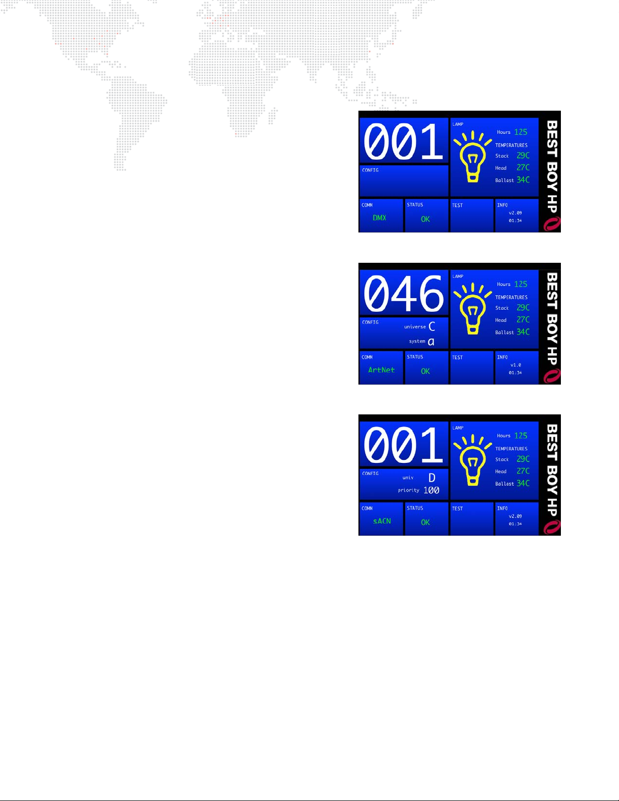
The Home screen consists of several sections (referred to as
"panels") which provide status and configuration information.
Pressing the panels on the touchscreen will open the applicable
sub-menus.
Address (#)
The large number is the current DMX or Ethernet (Art-Net/sACN)
address of the luminaire.
Press panel to bring up the numeric keypad for editing.
LAMP
+ Lamp Status - displays lamp on/off status, hours, and
temperatures. The lamp icon color indicates status of lamp: off
= gray icon, on = yellow icon (shown in example at right), error =
red icon.
+ Lamp Hours - displays total lamp hours. Lamp hours are
shown in green if under threshold, yellow at 650 hours, and red
at 750 hours.
750 hours.
+ Temperatures - displays luminaire head temperatures. The
temperatures are shown in green if under limit, yellow if close to
the limit, and red if over the limit.
It is mandatory that the lamp be changed before
Press panel to open Lamp Screen.
CONFIG
+ Universe - displays current Art-Net (alpha A-IV or numeric 0-
255) or sACN (alpha B-CPQN or numeric 1-63999) universe, if
present.
+ System/Priority - displays current Art-Net system or sACN
priority if either is present.
Press panel to open Configuration Screen.
COMM
+ Comm - displays currently active input protocol: Artnet (green/
red), sACN (green/red), DMX (green), or NONE (red). Ethernet
control is shown in green when the fixture's universe is present,
and red if absent.
Press panel to open Communication Screen.
STATUS
+ Status - displays fixture status: CAL (yellow), OK (green), or ERR (red).
Press panel to open Status Screen.
TEST
Press panel to open Te st Sc ree n.
INFO
+ Run Time - displays current software version and run time in
Press panel to open Information Screen.
32 BEST BOY® HP SPOT LUMINAIRE USER MANUAL
hours:minutes
format.
Page 41
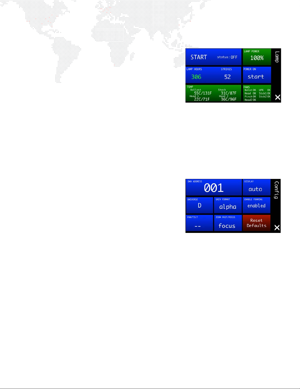
Lamp Screen
+ Start/Douse - displays current lamp status and power setting.
Press START/DOUSE to bring up Yes/No options (depending on
current lamp state).
+ Lamp Power - displays lamp power status as a percentage.
+ Lamp Hours- displays total lamp hours. Lamp hours are shown
in green if under threshold, yellow at 650 hours, and red at 750
hours.
hours.
It is mandatory that the lamp be changed before 750
Press to bring up Reset Lamp Hours Yes/No options.
+ Strikes - displays number of times the lamp has been struck.
Press to bring up Reset Lamp Hours Yes/No options.
+ Power On - sets option to strike lamp automatically upon power up. Press to bring up Wait/Start options.
+ Tem p - displays temperatures in Celsius and Fahrenheit. The temperature is shown in green if under limit, yellow
at 80°C, and red at 90°C. At 90°C the lamp will douse.
+ Fans - displays fan status as OK if fan is running, ERR (red) if fan is not running, or OFF (gray) if shut off due to
extended idle period.
Press (X) to return to Home Screen.
Configuration Screen
+ DMX Address - displays current DMX512 address. Press to
bring up numeric keypad for inputing the address.
+ Display - configures orientation of the Menu Touchscreen. Press
to bring up Auto/Up/Down options.
+ Universe - displays current universe. Press to bring up alpha
keypad or numeric keypad (based on universe format selection).
+ Universe Format - displays alpha/numeric universe format.
Press to bring up Alpha/Numeric options.
+ Enable Framing - displays current frame setting. Press to bring
up Enable/Disable options.
+ Pan/Tilt - displays summary of pan/tilt settings:
lock = pan or tilt is locked.*
swap = pan/tilt is swapped.
invert = pan or tilt is inverted.
free = "free" control is enabled (for operating fixture as a follow spot).
Press to bring up Pan/Tilt Screen.
+ Zoom Fast/Focus - option which allow the zoom to move as fast as possible (Fast), or to move a little slower and
retain focus while zooming (In Focus). Press to bring up Focus/Fast options.
+ Reset Defaults - resets all configuration settings and address to default values. Press to bring up "Reset All
Defaults" Yes/No options. Default settings are as follows:
- Address: 001
- Universe: A
- Universe Setting: alpha
- P/T: unlocked
- P/T: standard
(not inverted or swapped)
- Lamp Power Up: wait
- Zoom: in focus
- Display: auto
- Comm loss: no fade
- Moiré positions: gobo slot 5
- Framing: enabled
Press (X) to return to Home Screen.
* When Pan and/or Tilt are locked, it prevents the fixture from moving when the power is reset. For example, if a fixture is
placed within a piece of scenery that could interfere with Pan and Tilt calibration, they can be locked so that only the
internal mechanisms calibrate.
BEST BOY® HP SPOT LUMINAIRE USER MANUAL 33
Page 42
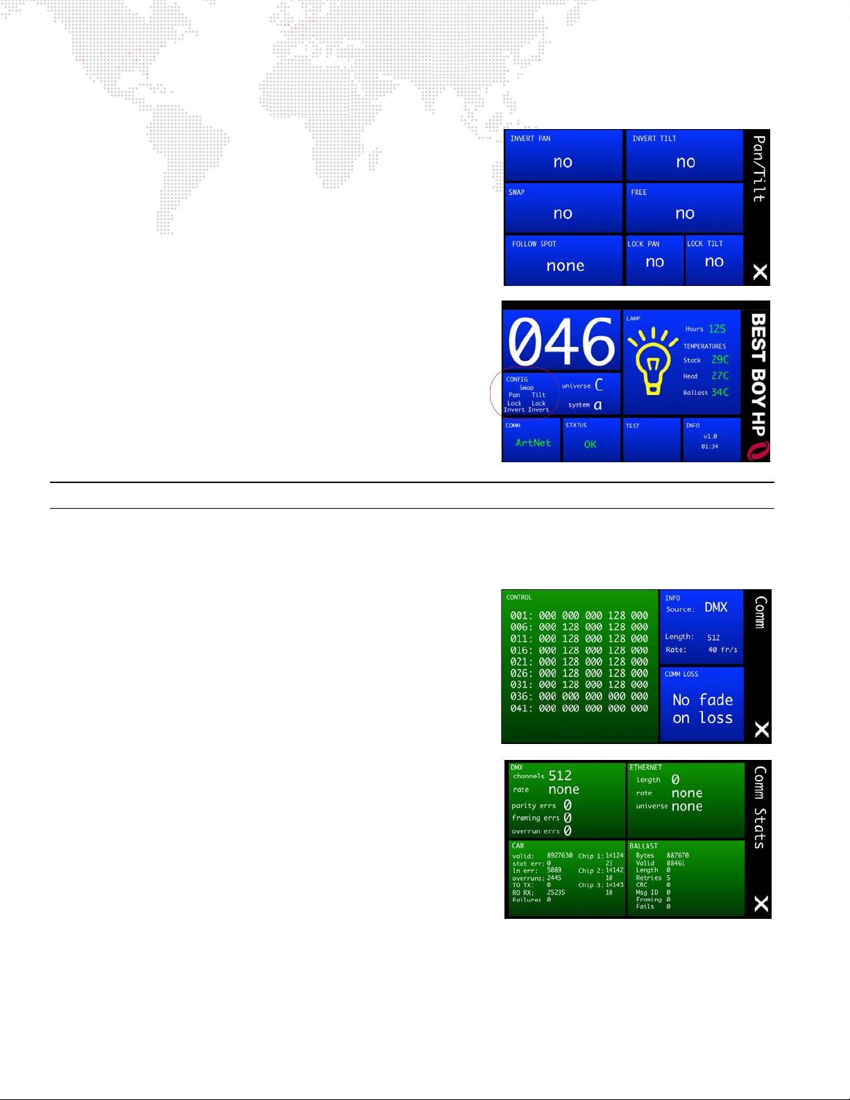
Pan/Tilt Screen
+ Invert Pan / Invert Tilt - displays current invert settings. Press
to bring up Invert Yes/No options. When inverted, pan/tilt will
move in the opposite direction.
+ Swap - displays current swap setting. Press to bring up Swap
Pan/Tilt Yes/No options. When swapped, the pan channel will
control tilt and vice versa.
+ Free - displays the current "free" setting. Press to bring up Yes/
No options. Yes will enable "free" control, which allows the
luminaire to be used as a followspot.
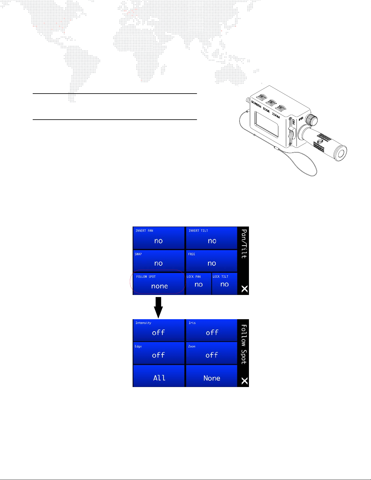
+ Follow Spot - displays which mechanisms are currently
enabled for followspot control (e.g., "intensity," "zoom/iris,"
"all," "none," etc.) Press to bring up the Follow Spot menu. (See
"Followspot Control" on page 37 for more information.)
+ Lock Pan/Tilt - displays current lock setting. Press to bring up
Lock Yes/No options. When locked, a mechanism will not
release brake or calibrate, only remain in its fixed position.
Once configured, any Pan/Tilt settings will be displayed in the
CONFIG panel of the Home screen as shown in the example to the
right.
Note: Pan/Tilt will retain its settings even if power is removed.
Press (X) to return to Lamp Screen.
Communication Screen
+ Control - displays current DMX512 control values. Values will
be highlighted in green when changing, yellow when being
controlled by a Followspot Controller. (Refer to "Followspot
Control" on page 37.)
+ Info - displays current source (DMX512 or Art-Net/Ethernet),
number of bytes in the frame, update rate, and universe
number (if Art-Net). Press INFO to bring up the Comm Stats
screen.
+ Comm Loss - configures how long to wait before the fixture
fades to black upon loss of comm data. Press COMM LOSS to
bring up "Set Trigger Fade After" option. Set to No Fade, 30
Seconds or 60 Seconds. (Also refer to "Configuring Comm
Loss Setting" on page 28.)
Press (X) to return to Home Screen.
34 BEST BOY® HP SPOT LUMINAIRE USER MANUAL
Page 43
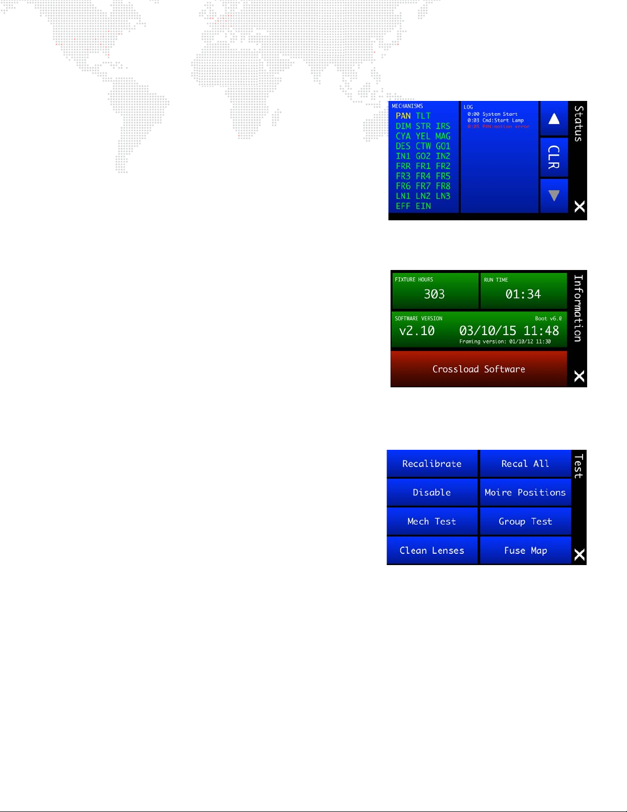
Status Screen
+ Mechanisms - displays mechanism status. Mechanism names
will be shown in yellow while calibrating, then change to green if
okay or red if an error exists. Locked mechanisms will be shown
in white. Press to bring up Test Screen.
+ Log - displays system status log. The log entries are stored in
persistent memory and are retained through power down. Use
touchscreen arrows to scroll up or down. Press CLR to bring up
Clear Log Yes/No options. Press the LOG panel itself to scroll
directly to the bottom, displaying the most recent log entries.
Press (X) to return to Home Screen.
Information Screen
+ Fixture Hours - displays total number of hours that the fixture has
been operated.
+ Run Time - displays current run time in
+ Software Version - displays operating software date and time,
along with Boot and Framing versions.
+ Crossload Software - allows the luminaire to send its software
version out over the DMX512 and Ethernet lines to other
connected luminaires in the daisy-chain. (See "Software
Crossload" on page 63 for more explanation of this function.)
Press (X) to return to Home Screen.
hours:minutes
format.
Test Screen
+ Recalibrate - press to bring up Recalibration Screen. (During
recalibration, intensity goes out until all mechanism calibrations
are complete and back in position, then fades in.)
+ Recal All - press to bring up Recalibrate All Yes/No options.
+ Disable - press to bring up Disable Screen, which allows specific
mechanisms to be disabled during testing.
+ Moiré Positions - press to bring up Moiré Gobos screen. (Moiré
gobos contain two pieces of glass: one that is fixed and another
that rotates. Due to this construction they do not contain
sensors, and therefore cannot be calibrated to a certain
orientation at startup as with standard gobos.) The Moiré Gobos screen is used to specify which wheel positions
contain Moiré gobos.
+ Mech Test - press to bring up Mechanical Tests Screen. (See "Mechanical Tests" on page 60 for more
explanation.)
+ Group Test - press to bring up Group Tests screen, which allows multiple luminaires to be run through a
configurable test sequence when chained together via DMX512 or Ethernet. (See "Group Tests" on page 61 for
more explanation.)
+ Clean Lenses - press to bring up Cleaning Lenses screen. This feature will position lenses so that all surfaces
may be cleaned with a cloth. (Note that pressing the buttons does not actually clean the lenses.)
+ Fuse Map - press to bring up Fuse Map screen. The Fuse Map provides the circuit board location for all
mechanism fuses.
Press (X) to return to Home Screen.
BEST BOY® HP SPOT LUMINAIRE USER MANUAL 35
Page 44
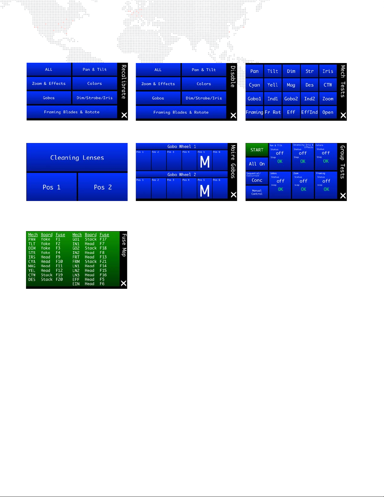
Test Sub-Menu Screens
Disable Screen - Specifies mechanisms
to be excluded from tests.
Moiré Gobos Screen - Prov ides a way to
specify which wheel positions contain
Moiré gobos (M).
Mechanical Tests Screen - Specifies
mechanisms to be tested.
Cleaning Lenses Screen - Positions
lenses so that th ey ma y be easi ly clea ned
with a cloth.
Recalibrate Screens - Specifies a
specific me chanism for recalibration.
Group Tests Screen - Allows multiple
luminaires to be tested when daisychained together.
Fuse Map - Provides the circuit board
location for all mechanism fuses.
36 BEST BOY® HP SPOT LUMINAIRE USER MANUAL
Page 45
Followspot Control
Followspot Controller
The Best Boy HP Luminaire can be controlled by a PRG Followspot Controller (FSC). In order to interface with this
device, followspot functionality and indicators are incorporated into luminaire’s menu system.
Note: For more information about FSC installation or
operation, refer to the PRG Followspot Controller User
Manual (02.9812.0060).
The Pan/Tilt menu provides a FOLLOW SPOT panel. This panel displays which mechanisms are currently enabled for
followspot control (e.g., "intensity," "zoom/iris," "all," "none," etc.)
Pressing FOLLOW SPOT brings up the Follow Spot menu. This menu is used to specify which mechanisms (of the
four available) are controlled by a Followspot Controller, which will override DMX control on those mechanisms.
BEST BOY® HP SPOT LUMINAIRE USER MANUAL 37
Page 46
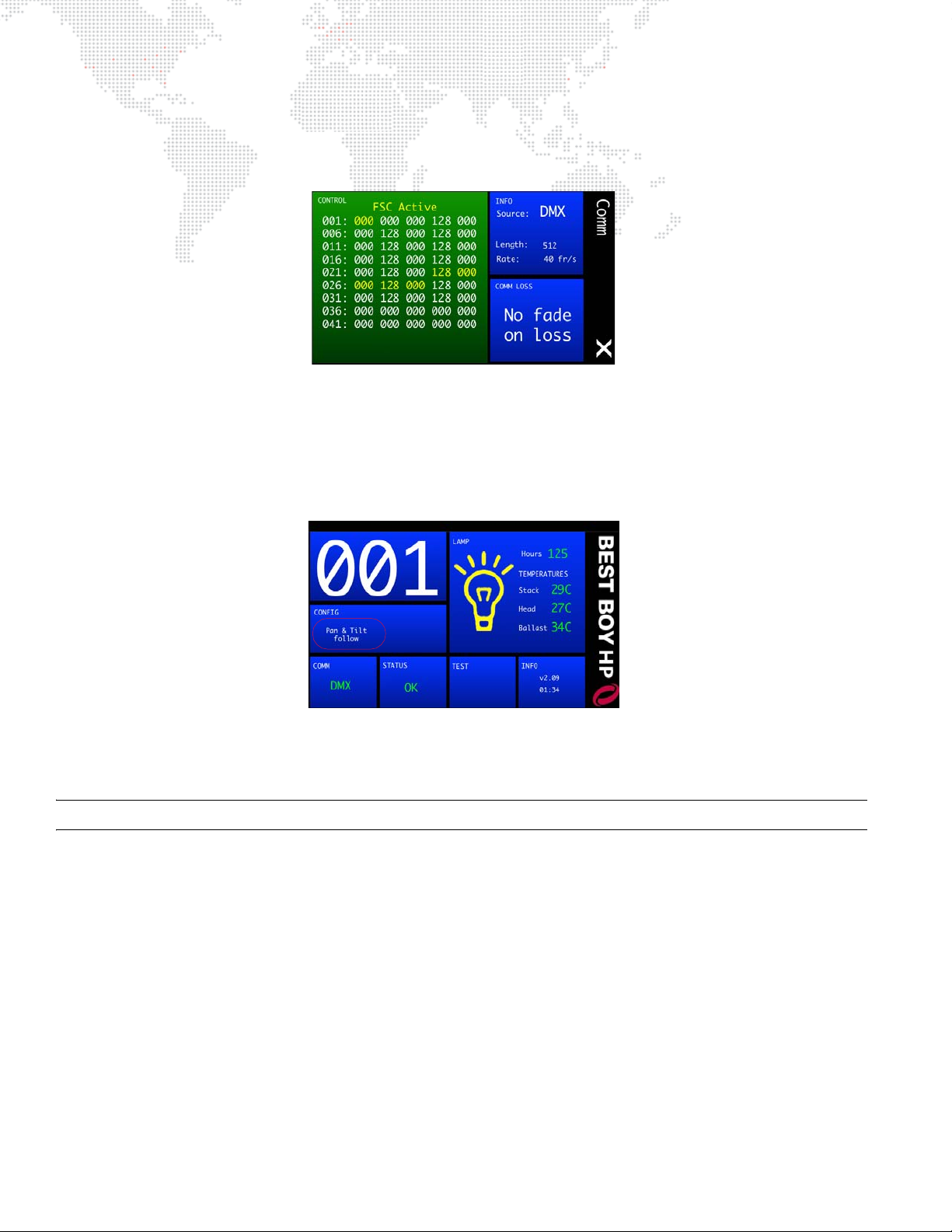
When any or all mechanisms are enabled for followspot control, "FSC Active" will be displayed in the Comm menu.
The DMX channels associated with the active FSC mechanism(s) will be highlighted in yellow to indicate that those
values come directly from the Followspot Controller and are not DMX-controlled.
When any mechanism has been enabled for followspot control, pan and tilt will automatically become free. Pan and
tilt will remain free until Followspot mode is turned off (all mechanisms deselected). At that time, upon exiting the Pan/
Tilt menu, pan and tilt will recalibrate (unless pan/tilt mode is changed to free or locked before exiting the Pan/Tilt
menu).
When pan and tilt are in Free mode due to followspot mechanisms being activated, “Pan & Tilt follow” will be
displayed in the CONFIG panel on the main menu.
Note that the Followspot Controller device does not need to be connected in order to enable followspot control on the
luminaire. If there is no FSC connected while in Followspot mode, the selected mechanisms will simply ignore DMX
until Followspot mode is exited.
Note: The FSC will control the selected mechanisms whether or not DMX is present on the attached fixture.
38 BEST BOY® HP SPOT LUMINAIRE USER MANUAL
Page 47
DMX512 OPERATION
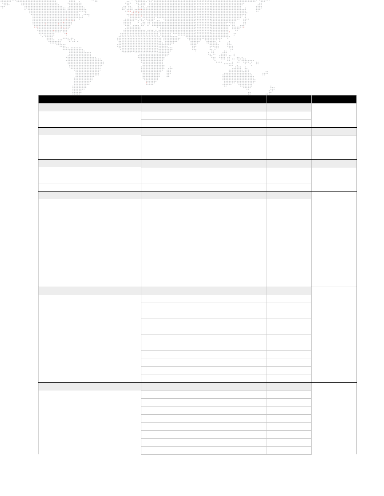
DMX Channel Mapping
Table 3-1: Best Boy DMX Channel Mapping
Channel Function Description 8-Bit 16-Bit
1 INTENSITY Intensity Adjustment home: 0
Out 0
Full 255
2 PAN Pan linear coarse adjustment home: 127 32768
0° 0
615° 255
3 Pan Fine Pan fine adjustment home: 0
4 TILT Tilt linear coarse adjustment home: 127 32768
0° 0
260° 255
5 Tilt Fine Tilt fine adjustment home: 0
6 CYAN Cyan Color Mix home: 0
Mix [Mode: Continuous] 0-255
Open 0
Full 255
Wheel Spin [Mode: Spin] 0-255
Clockwise
Fast 0
Slow 126
Stop 127-128
Counter-Clockwise
Slow 129
Fast 255
7 YEL LO W Yellow Color Mix home: 0
Mix [Mode: Continuous] 0-255
Open 0
Full 255
Wheel Spin [Mode: Spin] 0-255
Clockwise
Fast 0
Slow 126
Stop 127-128
Counter-Clockwise
Slow 129
Fast 255
8 MAGENTA Magenta Color Mix home: 0
Mix [Mode: Continuous] 0-255
Open 0
Full 255
Wheel Spin [Mode: Spin] 0-255
Clockwise
Fast 0
Slow 126
Stop 127-128
0-126
129-255
0-126
129-255
0-126
BEST BOY® HP SPOT LUMINAIRE USER MANUAL 39
Page 48
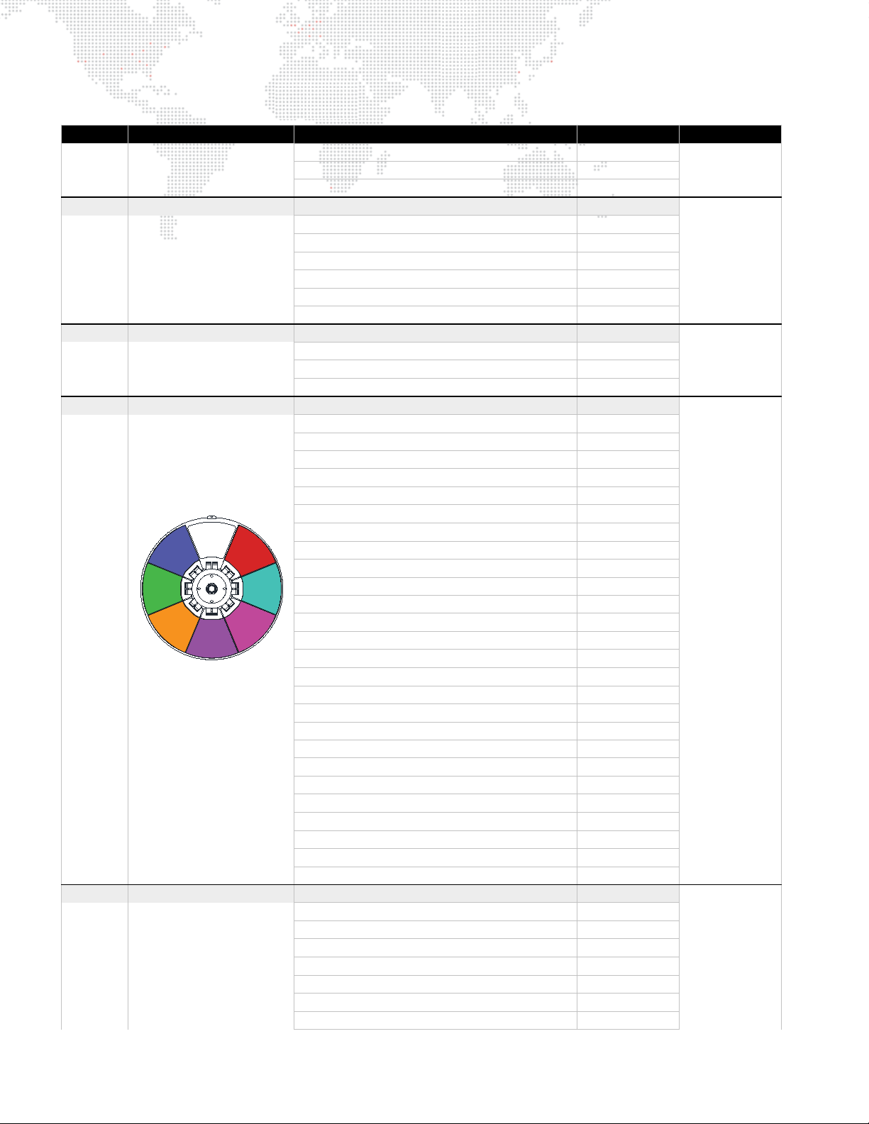
Table 3-1: Best Boy DMX Channel Mapping (Continued)
OPEN
1
2
3
4
5
6
7
Channel Function Description 8-Bit 16-Bit
Counter-Clockwise
Slow 129
Fast 255
9 COLOR MIX CONTROL Sets color mix control mode home: 0
Continuous 0-9
Spin Cyan 10-19
Spin Yellow 20-29
Spin Magenta 30-39
Spin ALL mixers 40-49
Reserved 50-255
10 COLOR TEMPERATURE Linear color temperature adjustment home: 50
7500k 0
Open 50
3000k 255
11 DESIGNER COLOR Color Wheel Choice home: 0
Color Choice [Mode: Continuous, Discrete, Strobe] 0-255
Open 0
Open / Color 1 26
Color 1 32
Color 1 / Color 2 42
Color 2 64
Color 2 / Color 3 79
Color 3 96
Color 3 / Color 4 114
Color 4 128
Color 4 / Color 5 145
Color 5 160
Color 5 / Color 6 175
Color 6 192
Color 6 / Color 7 208
Color 7 224
Color 7 / Open 232
Open 255
Wheel Spin [Mode: Spin] 0-255
Clockwise
Fast 0
Slow 126
Stop 127-128
Counter-Clockwise
Slow 129
Fast 255
12 DESIGNER CONTROL Sets Designer Wheel control mode home: 0
Continuous 0-9
Discrete 10-19
Spin 20-39
Strobe Random - Slow 40-43
Strobe Random - Medium 44-46
Strobe Random - Fast 47-49
Linear Strobe Rate 50-255
129-255
0-126
129-255
40 BEST BOY® HP SPOT LUMINAIRE USER MANUAL
Page 49
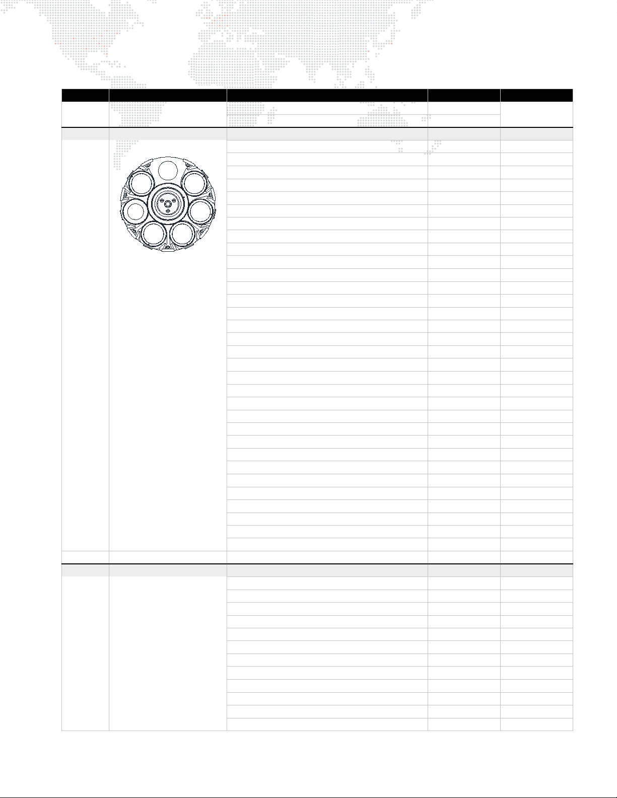
Table 3-1: Best Boy DMX Channel Mapping (Continued)
1
2
34
5
6
OPEN
Channel Function Description 8-Bit 16-Bit
Slow 50
Fast 255
13 GOBO 1 Rotating Gobo 1 Choice / Modifier home: 0 0
Discrete Choice
Open 0-9 0-2339
Gobo 1 10-18 2340-4679
Gobo 2 19-27 4680-7019
Gobo 3 28-35 7020-9359
Gobo 4 36-45 9360-11699
Gobo 5 46-54 11700-14039
Gobo 6 55-63 14040-16383
Continuous Choice
Open 64 16384
Open / Gobo 1 74 18850
Gobo 1 82 21014
Gobo 1 / Gobo 2 91 23400
Gobo 2 100 25661
Gobo 2 / Gobo 3 109 27980
Gobo 3 118 30284
Gobo 3 / Gobo 4 128 32760
Gobo 4 137 34966
Gobo 4 / Gobo 5 147 37543
Gobo 5 155 39642
Gobo 5 / Gobo 6 163 41833
Gobo 6 173 44288
Gobo 6 / Open 182 46513
Open 191 49150
Wheel Spin
Clockwise
Fast 192 49152
Slow 222 57087
Stop 223-224 57088-57599
Counter-Clockwise
Slow 225 57600
Fast 255 65535
14 Gobo 1 Fine Gobo 1 fine adjustment home: 0
15 GOBO 1 INDEX Rotating Gobo 1 Index Modifier home: 96 24575
Index Position
0° 0 0
180° 96 24575
360° 191 49151
Index Rotation
Clockwise
Fast 192 49152
Slow 222 57087
Stop 223-224 57088-57599
Counter-Clockwise
Slow 225 57600
Fast 255 65535
0-64 0-16383
64-191 16384-49150
192-255 49152-65535
192-223 49152-57343
225-255 57600-65535
0-191 0-49151
192-255 49152-65535
192-223 49152-57343
225-255 57600-65535
BEST BOY® HP SPOT LUMINAIRE USER MANUAL 41
Page 50
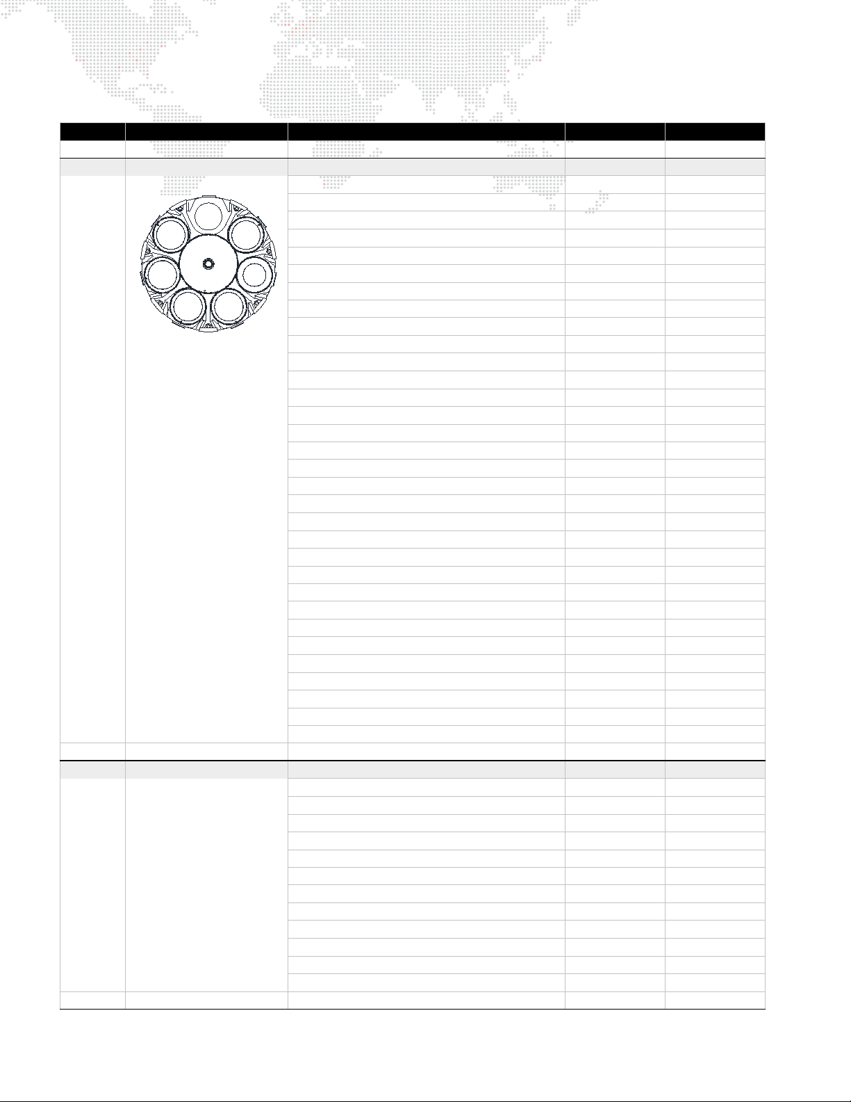
Table 3-1: Best Boy DMX Channel Mapping (Continued)
Channel Function Description 8-Bit 16-Bit
16 Gobo 1 Index Fine Gobo 1 Index fine adjustment home: 0
17 GOBO 2 Rotating Gobo 2 Choice / Modifier home: 0 0
Discrete Choice
OPEN
1
2
34
6
5
Open 0-9 0-2339
Gobo 1 10-18 2340-4679
Gobo 2 19-27 4680-7019
Gobo 3 28-36 7020-9359
Gobo 4 37-45 9360-11699
Gobo 5 46-54 11700-14039
Gobo 6 55-63 14040-16383
Continuous Choice
Open 64 16384
Open / Gobo 1 74 18850
Gobo 1 82 21014
Gobo 1 / Gobo 2 91 23400
Gobo 2 100 25661
Gobo 2 / Gobo 3 109 27980
Gobo 3 118 30284
Gobo 3 / Gobo 4 128 32760
Gobo 4 137 34966
Gobo 4 / Gobo 5 147 37543
Gobo 5 155 39642
Gobo 5 / Gobo 6 163 41833
Gobo 6 173 44288
Gobo 6 / Open 182 46513
Open 191 49150
Wheel Spin
Clockwise
Fast 192 49152
Slow 222 57087
Stop 223-224 57088-57599
Counter-Clockwise
Slow 225 57600
Fast 255 65535
18 Gobo 2 Fine Gobo 2 fine adjustment home: 0
19 GOBO 2 INDEX Rotating Gobo 2 Index Modifier home: 96 24575
Index Position
0° 0 0
180° 96 24575
360° 191 49151
Index Rotation
Clockwise
Fast 192 49152
Slow 222 57087
Stop 223-224 57088-57599
Counter-Clockwise
Slow 225 57600
Fast 255 65535
20 Gobo 2 Index Fine Gobo 2 Index fine adjustment home: 0
0-63 0-16383
64-191 16384-49150
192-255 49152-65535
192-223 49152-57343
225-255 57600-65535
0-191 0-49151
192-255 49152-65535
192-223 49152-57343
225-255 57600-65535
42 BEST BOY® HP SPOT LUMINAIRE USER MANUAL
Page 51
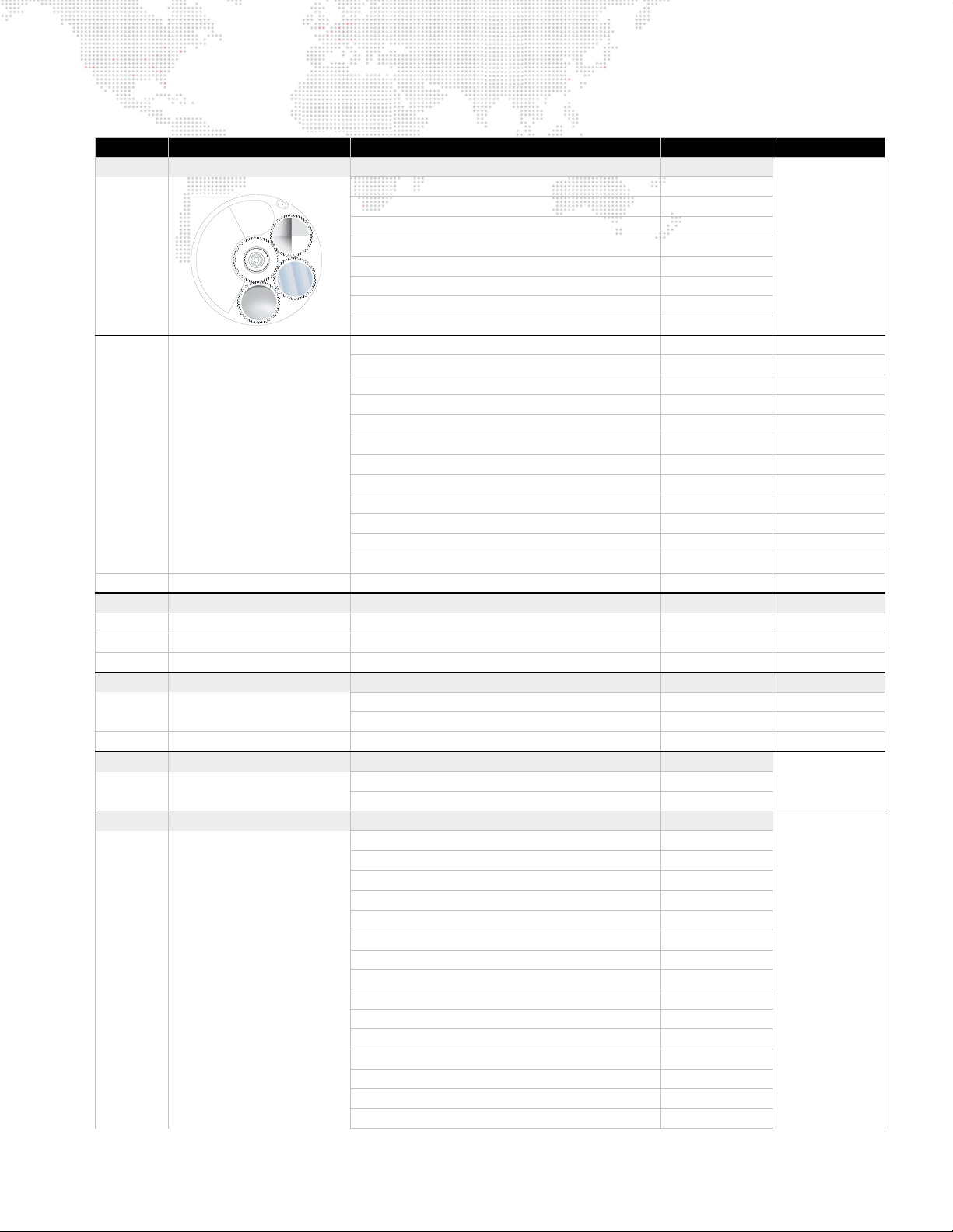
OPEN
1
2
3
VARIABLE
DIFFUSION
Table 3-1: Best Boy DMX Channel Mapping (Continued)
Channel Function Description 8-Bit 16-Bit
21 EFFECT Effect control home: 146
Discrete Choice
Gag 3 (Oblong) 0-35
Gag 2 (Extruder) 36-71
Gag 1 (4-Facet Prism) 72-107
Open 108-146
Varia b le Frost
Open 147
Full 255
22 EFFECT INDEX Effect Index control home: 96 home: 24575
Index Position
0° 0 0
360° 191 49151
Index Rotation
Clockwise
Fast 192 49152
Slow 222 57087
Stop 223-224 57088-57599
Counter-Clockwise
Slow 225 57600
Fast 255 65535
23 Effect Fine Effect fine adjustment home: 0
24 ZOOM Zoom coarse adjustment home: 94 home: 24064
8° (narrow) 0 0
64° (wide) 255 65535
25 Zoom Fine Zoom fine adjustment home: 0
26 EDGE Edge coarse adjustment home: 255 home: 65535
Near 0 0
Far 255 65535
27 Edge Fine Edge fine adjustment home: 255
28 BEAM IRIS Iris control home: 255
Small 0
Large 255
29 STROBE Strobe adjustment home: 0
Open 0-9
Closed 10-19
Pulse Clockwise
Fast 20
Slow 39
Pulse Counter-Clockwise
Slow 40
Fast 59
Ceiling Fan Clockwise
Fast 60
Slow 79
Ceiling Fan Counter-Clockwise
Slow 80
Fast 99
Slow Random 100-102
0-63
147-255
0-191 0-49151
192-255 49152-65535
192-223 49152-57087
225-255 57600-65535
20-39
40-59
60-79
80-99
BEST BOY® HP SPOT LUMINAIRE USER MANUAL 43
Page 52
Table 3-1: Best Boy DMX Channel Mapping (Continued)
Channel Function Description 8-Bit 16-Bit
Medium Random 103-106
Fast Random 107-109
Speed
Slow 110
Fast 255
30 MACRO Macro Control home: 0
None 0
Macro control overrides the
DMX control for that
parameter.
Iris - square wave 1
Iris - sine wave 2
Iris - sawtooth 3
Iris - reverse sawtooth 4
Iris close 5
Iris open 6
Zoom/Iris close 7
Zoom/Iris open 8
Framing - square wave 9
Framing - sine wave 10
Framing - sawtooth 11
Framing - reverse sawtooth 12
Framing close 13
Framing open 14
Zoom/Framing close 15
Zoom/Framing open 16
Iris/Framing alternate square wave 17
Iris/Framing alternate sine wave 18
Frost - sine wave 19
Frost - sawtooth 20
Frost - reverse sawtooth 21
Edge - sine wave 22
Edge - sawtooth 23
Edge - reverse sawtooth 24
Fire 25
Water 26
Clouds 27
31 MACRO SPEED Macro Speed control home: 0
Speed Range
Slow 0
Fast 246
Random Speed - Slow Rate 247-249
Random Speed - Medium Rate 250-252
Random Speed - Fast Rate 253-255
32 FOCUS TIME
33 COLOR TIME home: 255
34 IMAGE TIME home: 255
Refer to "Timing Channels" on page 48
35 BEAM TIME home: 255
110-255
0-246
home: 255
44 BEST BOY® HP SPOT LUMINAIRE USER MANUAL
Page 53
Table 3-1: Best Boy DMX Channel Mapping (Continued)
Channel Function Description 8-Bit 16-Bit
36 CONTROL Control Channels home: 0
Idle 0
All values must be held for a
minimum of 3 seconds to
take effect.
Recalibrate: All 10
Recalibrate: Erred Mechanisms 11
Recalibrate: Zoom/Edge and Effects 12
Recalibrate: Color 14
Recalibrate: Gobos 16
Recalibrate: Framing Blades and Rotate 17
Recalibrate: Dimmer/Strobe/Iris 18
Recalibrate: Pan/Tilt 19
Lamp: Douse 20
Lamp: Start 30
Zoom Table Select: 15
Zoom Table Select: 25
Zoom Table Select: 30
Zoom Table Select: 42
Zoom Table Select: 58
Zoom Table Select: 80
Zoom Table Select: 112
Zoom Table Select: 155
Zoom Table Select: 215
Zoom Table Select: 300
´ Throw 56
´ Throw 58
´ Throw (default) 60
´ Throw 62
´ Throw 64
´ Throw 66
´ Throw 68
´ Throw 70
´ Throw 72
´ Throw 74
Zoom Speed Select: Maintain Focus (default) 75
Zoom Speed Select: Move Fast 77
Gobo: Set Zero Position 80
Display: Turn Backlight ON 90
Display: Turn Backlight OFF 95
Pan: Lock 100
Pan: Unlock 102
Tilt: Lock 104
Tilt: Unlock 106
Pan/Tilt: Free Motion 108
Pan/Tilt: Free Lock 110
Pan/Tilt: End Free Motion 112
No Fade Out 114
Fade Out After 30s 116
Fade Out After 60s 118
Clear Logs 120
Invert Pan 122
Don't Invert Pan 124
Invert Tilt 126
Don't Invert Tilt 128
Swap Pan/Tilt 130
Don’t Swap Pan/Tilt 132
Followspot: Intensity/Iris 134
Followspot: Intensity/Iris/Edge 135
Followspot: Intensity/Iris/Edge/Zoom 136
Followspot: Intensity/Iris/Zoom 137
End Followspot Mode 138
BEST BOY® HP SPOT LUMINAIRE USER MANUAL 45
Page 54
Table 3-1: Best Boy DMX Channel Mapping (Continued)
Channel Function Description 8-Bit 16-Bit
Followspot: Intensity 139
Followspot: Intensity/Edge 140
Followspot: Intensity/Edge/Zoom 141
Followspot: Intensity/Zoom 142
Followspot: Iris 143
Followspot: Iris/Edge 144
Followspot: Iris/Zoom 145
Followspot: Iris/Edge/Zoom 146
Followspot: Edge 147
Followspot: Edge/Zoom 148
Followspot: Zoom 149
37 FRAMING 1 Blade 1A Position home: 0
Open 0
Inserted 255
38 FRAMING 2 Blade 1B Position home: 0
Open 0
Inserted 255
39 FRAMING 3 Blade 2A Position home: 0
Open 0
Inserted 255
40 FRAMING 4 Blade 2B Position home: 0
Open 0
Inserted 255
41 FRAMING 5 Blade 3A Position home: 0
Open 0
Inserted 255
42 FRAMING 6 Blade 3B Position home: 0
Open 0
Inserted 255
43 FRAMING 7 Blade 4A Position home: 0
Open 0
Inserted 255
44 FRAMING 8 Blade 4B Position home: 0
Open 0
Inserted 255
45 FRAMING ROTATE Blade rotation control home: 128
(-) Angle 0
Center 128
(+) Angle 255
Framing
channels can
be disabled or
enabled using
the "Enable
Framing"
option at the
CONFIG
menu. Refer
to page 33.
46 BEST BOY® HP SPOT LUMINAIRE USER MANUAL
Page 55

Special Notes
Macros
The Best Boy HP Luminaire offers 27 pre-defined sequences, called Macros, which allow for quick and easy control of
luminaire functions such as iris, zoom, framing, and more.
Macro control overrides the DMX control for that parameter. For example, if an iris macro is running, then the DMX
control for iris will not have any effect. Some macros also control multiple functions.
Gobo: Set Zero Position
Set Zero Position allows adjustment of the gobo wheel home position. Refer to "Gobo Set Zero Position" on page 52.
Zoom Tables
The zoom tables, which allow the fixture to maintain sharp focus on an image throughout the zoom range, are
sensitive to the throw distance. For this reason, a variety of zoom table versions are available for use with different
throws. The Zoom Table Select values are handled live to allow cue recall with different zoom tables. If the zoom value
changes and the control channel is on one of the zoom select values, the indicated zoom table will be used for that
zoom recall.
Note also that zoom table select is not persistent between power cycles, it always resets to the default 30' table at
power-up.
Framing
The Framing channels are optional, as controlled by the "Enable Framing" menu selection. (Refer to "Configuration
Screen" on page 33.)
The blade positions are as follows:
4B 4A
1A 1B
BLADE 1
BLADE 4
FIXTURE BEAM
BLADE 3
3B 3A
Figure 3-4: Blade Positions
2A 2B
BLADE 2
BEST BOY® HP SPOT LUMINAIRE USER MANUAL 47
Page 56
Timing Channels
Channel Functions
Timing channel control improves the timed moves of certain groups of parameters. Four timing channels are provided
for this purpose: Focus, Color, Beam, and Image.
Timing channels support time values of up to six minutes.
Table 3-2: Timing Channel Allocations
Channel Function Timing Channel
Pan
Tilt
Cyan
Yellow
Magenta
Color Wheel
Zoom
Edge
Iris
Framing
Rotating Gobo Wheels 1 & 2
Gobo Index 1 & 2
Effects Wheel
Effects Index
Focus
Color
Beam
Image
Timing Channel Mapping
Refer to the Timing Channels Table starting on the next page. The following guidelines apply:
+ A timing value of zero is full speed.
+ A time value of 100% (or 255 in DMX) causes the associated parameter(s) to follow cue fade time (console time)
rather than the timing channel.
+ Timing channels can be set in either % or 0-255 (DMX) modes, with the values assigned - as shown in the tables.
48 BEST BOY® HP SPOT LUMINAIRE USER MANUAL
Page 57

Table 3-3: Timing Channels
% Value DMX = Seconds
0 Full Speed
10.2
20.4
13 0.6
40.8
25 1
61.2
71.4
38 1.6
91.8
410 2
11 2.2
12 2.4
513 2.6
14 2.8
615 3
16 3.2
17 3.4
718 3.6
19 3.8
820 4
21 4.2
22 4.4
923 4.6
24 4.8
10 25 5
26 5.2
27 5.4
11 28 5.6
29 5.8
30 6
12 31 6.2
32 6.4
13 33 6.6
34 6.8
35 7.0
14 36 7.2
37 7.4
15 38 7.6
39 7.8
40 8
16 41 8.2
42 8.4
17 43 8.6
44 8.8
45 9
18 46 9.2
47 9.4
19 48 9.6
49 9.8
50 10
20 51 10.2
Table 3-3: Timing Channels (Continued)
% Value DMX = Seconds
52 10.4
53 10.6
21 54 11
55 11
22 56 12
57 12
58 13
23 59 13
60 14
24 61 14
62 14
63 15
25 64 15
65 16
26 66 16
67 16
68 17
27 69 17
70 18
28 71 18
72 18
73 19
29 74 19
75 20
30 76 20
77 20
78 21
31 79 21
80 21
81 22
32 82 22
83 23
33 84 23
85 23
86 24
34 87 24
88 25
35 89 25
90 25
91 26
36 92 26
93 27
37 94 27
95 27
96 28
38 97 28
98 29
39 99 29
100 29
101 30
40 102 30
103 30
104 31
BEST BOY® HP SPOT LUMINAIRE USER MANUAL 49
Page 58

Table 3-3: Timing Channels (Continued)
Table 3-3: Timing Channels (Continued)
% Value DMX = Seconds
41 105 31
106 32
42 107 32
108 32
109 33
43 110 33
111 34
44 112 34
113 34
114 35
45 115 35
116 36
46 117 36
118 36
119 37
47 120 37
121 38
48 122 38
123 38
124 39
49 125 39
126 39
127 40
50 128 40
129 41
51 130 41
131 41
132 42
52 133 42
134 43
53 135 43
136 43
137 44
54 138 44
139 45
55 140 45
141 45
142 46
56 143 46
144 47
57 145 47
146 47
147 48
58 148 48
149 49
59 150 49
151 49
152 50
60 153 50
154 50
155 51
61 156 51
157 52
% Value DMX = Seconds
62 158 52
159 52
160 53
63 161 53
162 54
64 163 54
164 54
165 55
65 166 55
167 56
66 168 56
169 56
170 57
67 171 57
172 58
68 173 58
174 58
175 59
69 176 59
177 59
178 60
70 179 60
180 65
71 181 65
182 65
183 70
72 184 70
185 75
73 186 75
187 75
188 80
74 189 80
190 85
75 191 85
192 85
193 90
76 194 90
195 95
77 196 95
197 95
198 100
78 199 100
200 110
79 201 110
202 110
203 120
80 204 120
205 120
81 206 130
207 130
208 140
82 209 140
210 140
50 BEST BOY® HP SPOT LUMINAIRE USER MANUAL
Page 59

Table 3-3: Timing Channels (Continued)
% Value DMX = Seconds
211 150
83 212 150
213 160
84 214 160
215 160
216 170
85 217 170
218 180
86 219 180
220 180
221 190
87 222 190
223 200
88 224 200
225 200
226 210
89 227 210
228 210
229 220
90 230 220
231 230
91 232 230
233 230
234 240
92 235 240
236 250
93 237 250
238 250
239 260
94 240 260
241 270
95 242 270
243 270
244 280
96 245 280
246 290
97 247 290
248 290
249 300
98 250 300
251 310
99 252 310
253 310
254 310
100 255 Follows Cue Data
BEST BOY® HP SPOT LUMINAIRE USER MANUAL 51
Page 60
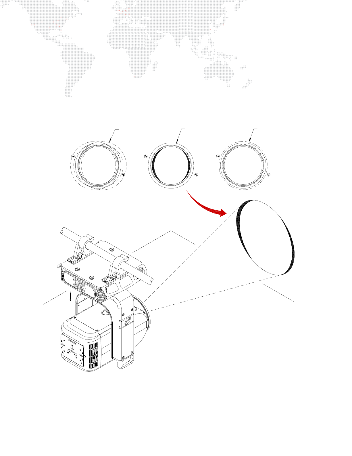
Gobo Set Zero Position
OUT OF ALIGNMENT PROPERLY ALIGNED
GOBO WHEEL
The Gobo Set Zero command allows adjustment of the gobo wheel’s home position. When this command is issued,
the luminaire sets the current wheel position as the "zero" position and stores this offset so it will be retained at the
next startup. This allows correction for a sensor that may be slightly out of position causing the gobo wheel to not be
perfectly centered and therefore obstructing part of the beam in the open position.
To set zero position:
Step 1. Using console, move wheel into desired center position.
Step 2. Execute Set Zero Position command (Control Channel DMX value 80). The luminaire will now remember the
setting as the new zero position.
52 BEST BOY® HP SPOT LUMINAIRE USER MANUAL
Figure 3-5: Gobo Alignment
Page 61

4.
TROUBLESHOOTING AND MAINTENANCE
This chapter provides a basic troubleshooting guide, along with procedures for testing, proper
handling, and routine maintenance.
TROUBLESHOOTING
+
+ TEST ING
+ SOFTWARE UPDATE
+ EQUIPMENT HANDLING
+ ROUTINE MAINTENANCE
Page 62
TROUBLESHOOTING
Troubleshooting Guide
The following table provides a list of common start-up problems and possible solutions.
Symptom Solution(s) Refer to...
Ensure power cable is properly connected to Neutrik
input connector.
No power to luminaire.
Ensure power is switched on at source (mains,
disconnect box, etc.)
Ensure DMX512 or Ethernet data cable is properly
No console control.
connected.
Ensure DMX512 address setting is correct. page 25
Ensure data cables are correctly configured.
DMX512 control not working
correctly throughout daisy-chain.
Ensure termination connector is installed at last
luminaire in data link.
Lamp does not strike at power-up. Configure lamp to start at power-up.
Comm LED is red indicating that no
valid DMX or Ethernet signal is
detected.
Ensure DMX512 or Ethernet data cable is properly
connected.
Check console.
Ensure that luminaire is not also receiving a DMX
No Ethernet control.
signal. If both valid DMX and Ethernet control are
being received, DMX control will take precedence.
page 10
n/a
page 21
page 21
page 12
page 33
page 21
page 24
Beam obstructed by gobo in open
position.
Luminaire won’t take software
update.
Light spill occurring at some zoom
angles.
Comm LED flashing red or green.
54 BEST BOY® HP SPOT LUMINAIRE USER MANUAL
Set new gobo zero position.
Remove active control (DMX512 or Art-Net).
Engage Light Shield.
Indicates an internal error on the fixture. Check Status
screen to isolate.
page 52
page 63
page 20
page 55
Page 63
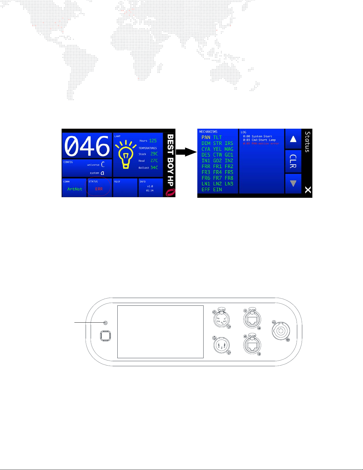
Errors
100 -240 VAC
12A Max
50 / 60 Hz
IN
DMX
THRU
ETHERNET
AC IN
COMM
WAKE
Comm LED
Status Indications
The STATUS panel at the Home screen will report overall luminaire conditions as follows:
+ CALIBRATION (yellow)
+ OK (green)
+ ERROR (red)
+ LOCKED (white)
Pressing the STATUS panel will bring up a detailed Status screen as shown below:
The Status screen will indicate which specific mechanisms, if any, have errors. It also provides a log of systems
activity. The Status screen operates as follows:
+ Mechanisms - displays mechanism status. Mechanism names will be shown in yellow during calibration, green if
okay, and red if an error exists. If an error exists, press the Mechanisms panel to bring up the Recalibration
screen. Try recalibrating the mechanism(s) that is reporting the error.
+ Log - displays system log. Use touchscreen arrows to scroll up or down. Press CLR to bring up Clear Log Yes/No
options.
Comm LED
In the case of a mechanism error, the Comm LED on the input panel will flash either red or green (depending on the
comm state).
Figure 4-1: Comm LED
BEST BOY® HP SPOT LUMINAIRE USER MANUAL 55
Page 64

Mechanism Errors
Errors will be shown after the mechanism code, for example: PAN:Comm Error.
Error Code Explanation Solution
Cal Error
Cal Timeout
Comm Error
Get Position Error
Init Error
Motion Error
No Sensor
No Stop
Sensor Stuck
Spin Error
Error resetting position values in motion
processor at beginning of calibration
An action during calibration took longer
than expected
Error communicating with motion
processor
Error when retrieving current position
from motion processor
Error during initialization of motion
processor
Mechanism's actual position is too far
from its commanded position
During calibration, no sensor was found
in the range of travel
Mechanism which calibrates to a
physical stop did not find that stop
During calibration, could not find either
edge of the sensor or the sensor did not
turn off as expected
Error while sending spin command to
motion processor
Check CAN cables/connections, motor
control board
Check CAN cables/connections, motor
control board
Check CAN cables/connections, motor
control board
Check CAN cables/connections, motor
control board
Check CAN cables/connections, motor
control board
Check mechanism motion
Check for mechanism motion, sensor
operation
Check mechanism
Check for mechanism motion, sensor
operation
Check CAN cables/connections, motor
control board
Stop Spin Error
Error while sending stop spin command
to motion processor
Check CAN cables/connections, motor
control board
Other Errors
Error Code Explanation Solution
Ballast Errors: Parity, Overrun,
Bad Header, Msg Too Long
Ballast Heat Sink Over Temp Ballast too hot Check fans
Ballast Short Detected Short circuit on ballast output Check wiring
Ballast Timeout: Lamp Strike Lamp failed to strike Check igniter, lamp
CAN Comm Error
Crossload Timeout
Data not crossload format
DMX busy: cancel crossload
DMX: UART transmit error Transmit buffer busy when trying to send Remove any incoming DMX, retry
Fuse Blown One or more fuses are blown Check fuse on specified board
Various ballast errors Check ballast comm cable/connections
Stopped receiving CAN messages from
motion processor
Crossload execution took too long due to
error
Data in memory is not proper format for
crossload
Cannot execute crossload with traffic on
DMX line
Check CAN cables/connections, motor
control board
Remove any incoming DMX, retry
Load software via computer
Remove incoming DMX control for cross
load
56 BEST BOY® HP SPOT LUMINAIRE USER MANUAL
Page 65

Error Code Explanation Solution
Gobo out of zero range
When zeroing gobo wheels, the wheel is
too far away from zero to set the position
Move wheel closer to home position
before zero command
Head Fan Error Fan not running properly Check fan
In Free Mode: Can’t Lock Free mode is enabled
Lamp Off
Fan Error: Cannot strike lamp while any
fan is in error state
Use pan/tilt menu to change from "free"
to "lock"
Check fan, fan cabling
Lamp Off: Over Temperature Head temperature too high Check fans
Lamp over threshold
Must Unlock via Free Option Lock is enabled
Lamp hours above recommended
maximum
Change lamp
Use pan/tilt menu to change from "lock"
to "norm"
Plenum Fan Error Fan not running properly Check fan
PMD Motion Error
Mechanism's actual position is too far
from its commanded position
Check mechanism motion
Framing Motor Disabled Framing not running properly Recalibrate, check mechanism motion
Stack Fan Error
One or more stack fans not running
properly
Check fan, fan cabling
Temp over threshold Temperature too high Check fans/filters
Tip Fan Error Fan not running properly Check fan
UPE Fans Error
Upper Enclosure fans not running
properly
Check fan, fan cabling
Yoke Fan Error Fan not running properly Check fan
BEST BOY® HP SPOT LUMINAIRE USER MANUAL 57
Page 66
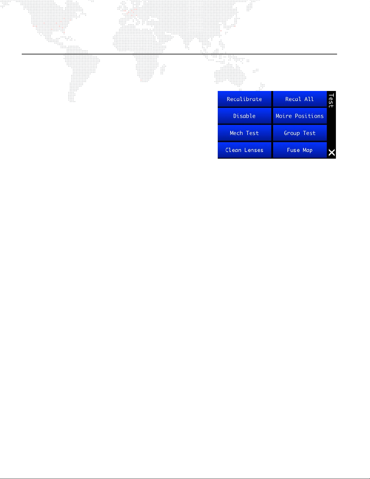
TES TIN G
Test Screen
The Test menu provides options for using the luminaire’s self-test features.
+ Recalibrate - press to bring up Recalibration Screen. (During
recalibration, intensity goes out until all mechanism calibrations
are complete and back in position, then fades in.)
+ Recal All - press to bring up Recalibrate All Yes/No options.
+ Disable - press to bring up Disable Screen, which allows specific
mechanisms to be disabled during testing.
+ Moiré Positions - press to bring up Moiré Gobos screen, which
provides a way to specify the wheel positions containing Moiré
gobos. Moiré gobos contain two pieces of glass: one that is fixed
and another that rotates. Due to this construction they do not
contain sensors, and therefore cannot be calibrated to a certain orientation at startup as with standard gobos.
+ Mech Test - press to bring up Mechanical Tests Screen. (See "Mechanical Tests" on page 60 for more
explanation.)
+ Clean Lenses - press to bring up Cleaning Lenses screen. This feature will position lenses so that all surfaces
may be cleaned with a cloth. (Note that pressing the buttons does not actually clean the lenses.)
+ Group Test - press to bring up Group Tests screen, which allows multiple luminaires to be run through a
configurable test sequence when chained together via DMX512 or Ethernet. (See "Group Tests" on page 61 for
more explanation.)
58 BEST BOY® HP SPOT LUMINAIRE USER MANUAL
Page 67
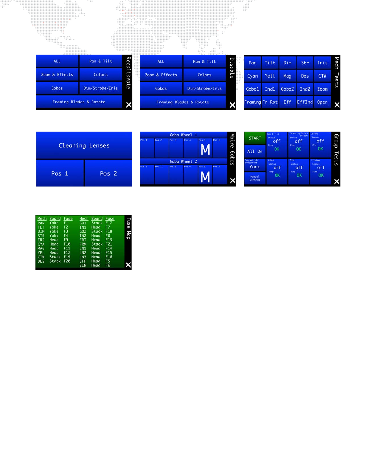
Test Sub-Menu Screens
Disable Screen - Specifies mechanisms
to be excluded from tests.
Moiré Gobos Screen - Prov ides a way to
specify which wheel positions contain
Moiré gobos (M).
Mechanical Tests Screen - Specifies
mechanisms to be tested.
Cleaning Lenses Screen - Positions
lenses so that th ey ma y be easi ly clea ned
with a cloth.
Recalibrate Screens - Specifies a
specific me chanism for recalibration.
Group Tests Screen - Allows multiple
luminaires to be tested when daisychained together.
Fuse Map - Provides the circuit board
location for all mechanism fuses.
BEST BOY® HP SPOT LUMINAIRE USER MANUAL 59
Page 68
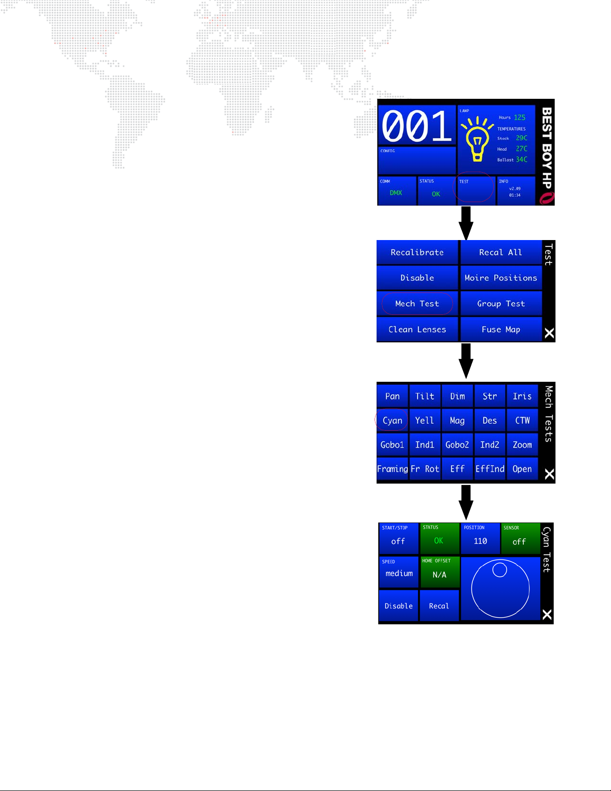
Mechanical Tests
The Mechanical Tests menu provides a method for exercising all
luminaire mechanisms individually. Each mechanism has a similar Test
screen. Cyan is shown in the example to the right.
The following test functions are available:
+ Test Ch ase - The mechanism will move back and forth between
two positions. The START/STOP button starts and stops the
motion, and the SPEED button sets the rate of the motion. For
mechanisms with sensors, one of the positions will be on the
sensor and the other position will be off.
+ Manual Control - The knob at the bottom right of the screen
moves the mechanism through its range of travel, manually.
+ Manual Position Entry - Press POSITION to enter a value for the
mechanism's position.
+ Feedback -The current status of the mechanisms encoder
(POSITION) and sensor (SENSOR) are shown (if available for that
mechanism). STATUS indicates whether the mechanism is in an
error state or normal operating state.
+ Utility Functions - Press Recalibrate to recalibrate the
mechanism or Disable to turn off the motor control to allow the
mechanism to move freely.
+ Configuration Information - HOME OFFSET indicates whether
the home position* has been adjusted to fine tune sensor positions
(applies to gobo wheel only; refer to Control Channel settings in
"DMX Channel Mapping" on page 39).
* Due to small variations in sensor and sensor board positions, the open
position on a gobo wheel might not be precisely aligned with the optical
axis, creating a slight blockage on one side of the open beam. Adjust
the wheel position via DMX to get the proper alignment and send the
HOME OFFSET command to store the current position as the new
"home" position. This position is stored in persistent memory and will
be used going forward as the home position.
60 BEST BOY® HP SPOT LUMINAIRE USER MANUAL
Page 69
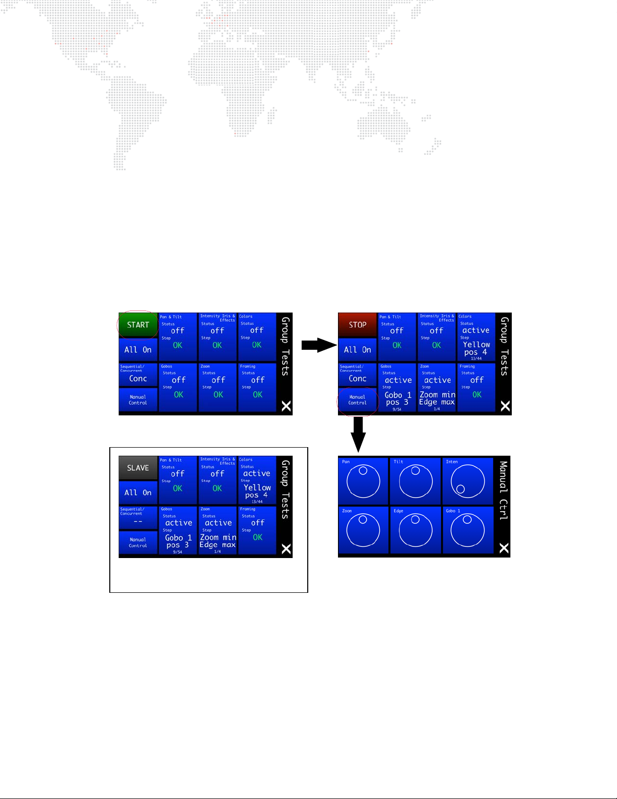
Group Tests
Slave fixtures will display "SLAVE"
in the Group Tests screen as shown.
The Group Test menu allows multiple Best Boy HP Luminaires to be run through a configurable test sequence when
chained together via DMX512 or Ethernet. (Refer to "Connecting Power and Data" on page 21 for more information
about daisy-chaining.)
To perform a group test:
Step 1. At Group Test screen, select options to run: Pan/Tilt, Intensity, Colors, Gobos, Zoom, and/or Framing.
Step 2. Select test option: Concurrently (all selected tests are run at once) or Sequentially (tests are run one at a
time as each one finishes).
Step 3. Press START to begin testing. All luminaires connected to the main fixture (now referred to as the "Master")
will become "Slaves" and follow the test routine set on the Master in an endless loop.
Step 4. To stop the test sequence, press STOP on the Master.
While in group test, a Master can manually change certain values by using the Manual Control screen. From here, you
can adjust the levels of parameters not active in the test sequence. For example, if a test were running on gobos and
colors, you can adjust the pan and tilt to point the Master and all Slaves to a position where it will be easier see the
output of the fixtures.
BEST BOY® HP SPOT LUMINAIRE USER MANUAL 61
Page 70
SOFTWARE UPDATE
Mac/PC Ethernet Best Boy Ethernet Best Boy ...
Mac/PC Ethernet Series 400 Ethernet Best Boy Ethernet Best Boy ...
Mac/PC Ethernet Series 400 DMX Best Boy DMX Best Boy ...
Mac/PC Ethernet PRG Node DMX Best Boy DMX Best Boy ...
Software Update Using LumLoader Application
Introduction
The LumLoader application allows you to update the software in a Best Boy HP Luminaire. The update will be sent
over an Ethernet connection. The luminaire can take the Ethernet input directly, or the update can be translated to
DMX512 signal with an appropriate device, either Series 400® or a PRG Node (with the required software update).
The fixtures can be daisy-chained to load multiple fixtures at once.
Supported configurations:
Note: There should be no active control (DMX512 or Ethernet) during the update process.
Preparation - Java
The loader (LumLoader) is a Java application which can be run on a Mac or a PC computer.
Note: Microsoft Windows® and new Mac computers do not come with the required Java run-time library installed, so
you may need to go to the Sun website (java.com/getjava/) to download Java.
Selecting an Ethernet Interface
Connect the computer to the system, and start the LumLoader application. When the application starts, it will ask
which active Ethernet port should be used. Select the appropriate port. You may be able to differentiate the ports by
IP address, compared with your network setup. Typically the en0 is the first built-in Ethernet port, and other interfaces
could include additional network ports or wireless adapters.
Selecting the Module
The loader can support multiple versions of software, so make sure the appropriate version is selected. The default
version will typically be fine.
Download the Software
Press "Start Download" to initiate the update. You should see the luminaires immediately drop into the startup screen
and erase flash, which takes about 30 seconds. Then the new module is sent out, the screen indicates "Loading",
and when complete they will go back to the main menu and start calibration.
If the fixture already has the update software version, it will not attempt the update.
62 BEST BOY® HP SPOT LUMINAIRE USER MANUAL
Page 71
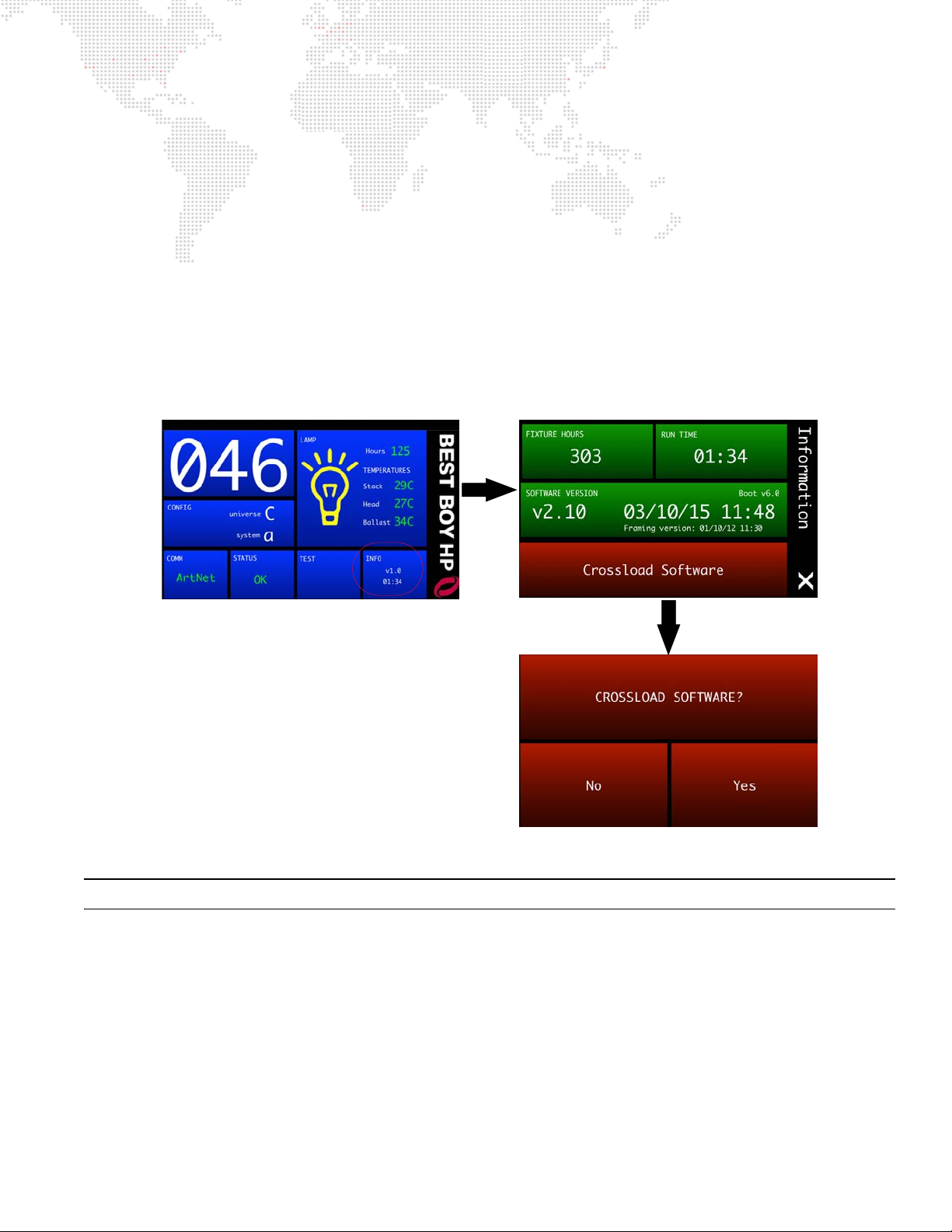
Troubleshooting
+ If the LumLoader application does not start up, make sure the Java library is installed.
+ Make sure the network port is active before starting the application. Sometimes it takes several seconds for the
operating system to recognize the network link.
+ Make sure there is only one instance of the LumLoader application running.
+ Wireless should be disabled on the computer.
Software Crossload
The Information menu provides a method for sending a luminaire’s current software version to all connected
luminaires. (Luminaires can be daisy-chained via DMX512 or Ethernet.)
To initiate the software crossload, press Crossload Software at the Information screen. At confirmation screen, press
"Yes." If a connected luminaire already has that software version, it will do nothing. If it does not have the same
version, it will go into the boot screen and start updating.
Note: There should be no active control (DMX512 or Ethernet) during the update process.
BEST BOY® HP SPOT LUMINAIRE USER MANUAL 63
Page 72
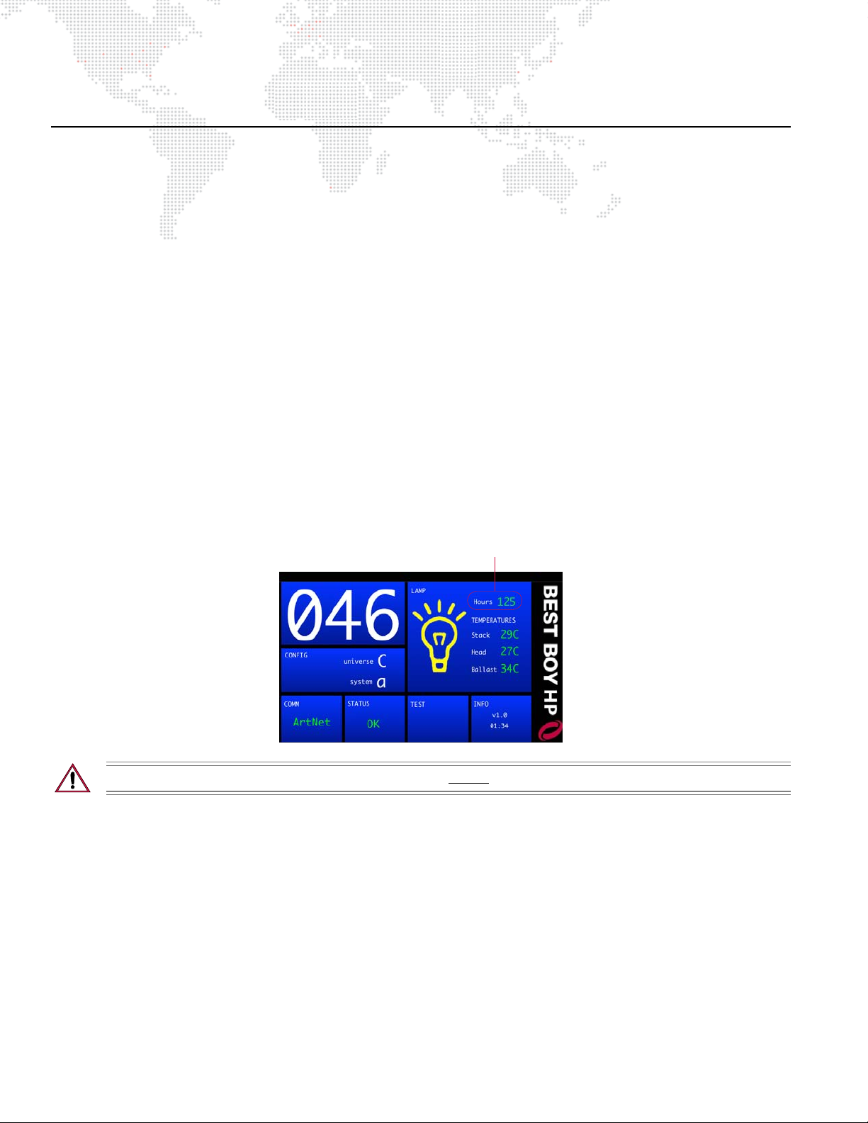
EQUIPMENT HANDLING
Lamp hours
Proper Lamp Servicing and Operation
Servicing
+ When handling a lamp, hold it by the ceramic base while wearing cotton gloves or finger cots. Do not touch the
glass envelope (bulb). If you touch the glass with bare fingers, wipe off any fingerprints with alcohol.
Heat
+ When lamps are lit, the interior of the luminaires becomes very hot. To aid in the airflow circulation within the
luminaires, after dousing the lamps, wait 5 minutes before removing power to the luminaires. This will provide
enough time for the equipment fan to cool off the unit.
Lamp Life
+ When operating arc lamps, allow luminaires to operate for at least 3 minutes. It takes about 3 minutes for the fill
components (mercury and halogen-metal compounds) in the lamp tubes to vaporize completely. If the lamps are
switched off earlier than 3 minutes, the fill components are partially vaporized. The inadequately vaporized fill
components and the electrode material (tungsten) are deposited in the areas of the lamp tubes that have
remained cool. As a result, the lamp tubes blacken prematurely and reduce the service lives of the lamps.
+ If system will be unattended for more than 3-4 hours, luminaire lamps should be doused.
+ The lamp indicator (available on the menu Home screen) displays total lamp hours. Lamp hours are shown in
green if under threshold, yellow at 650 hours, and red at 750 hours.
before 750 hours.
It is mandatory that the lamp be changed
CAUTION: It is mandatory that the lamp be changed before 750 hours.
64 BEST BOY® HP SPOT LUMINAIRE USER MANUAL
Page 73
ROUTINE MAINTENANCE
Replacing the Lamp
Parts:
71.2550.1500.0 / 2.3749D-11 1 EA LAMP, HTI 1500W/D7/60
Tools:
Cotton gloves or finger cots
Alcohol wipe (supplied with new lamp)
WARNING: Remove power from luminaire before performing any maintenance procedures.
CAUTION: Refer to "Proper Lamp Servicing and Operation" on page 64 before handling the lamp.
CAUTION: Wear cotton gloves or finger cots while servicing lamp. Touching the lamp glass with bare fingers
will leave oil and cause the lamp to explode or burn out early. Clean with alcohol wipe after installing.
To replace lamp:
Step 1. If luminaire is powered-up, douse lamp and allow fans to run for at least 5 minutes.
Step 2. Remove power from luminaire.
Step 3. At lamp access door, loosen four captive screws (two on each side). Refer to Figure 4-2 on next page.
Step 4. Pull lamp box out of head assembly and rotate 90 degrees to access lamp.
Step 5. Grasp lamp at metal ends and carefully remove from lamp box.
Step 6. While holding new lamp at metal ends, install lamp so that nipple faces rear of luminaire (towards reflector).
Step 7. Ensure lamp base is fully seated so that it touches contacts on both ends of socket.
Step 8. Using supplied alcohol wipe, carefully - but thoroughly - clean glass bulb.
Step 9. Re-insert lamp box into head and tighten four captive screws.
Step 10. Reset Lamp Hours. (Refer to "Lamp Screen" on page 33.)
Step 11. Optimize lamp. (Refer to "Adjusting Lamp" on page 67.)
BEST BOY® HP SPOT LUMINAIRE USER MANUAL 65
Page 74
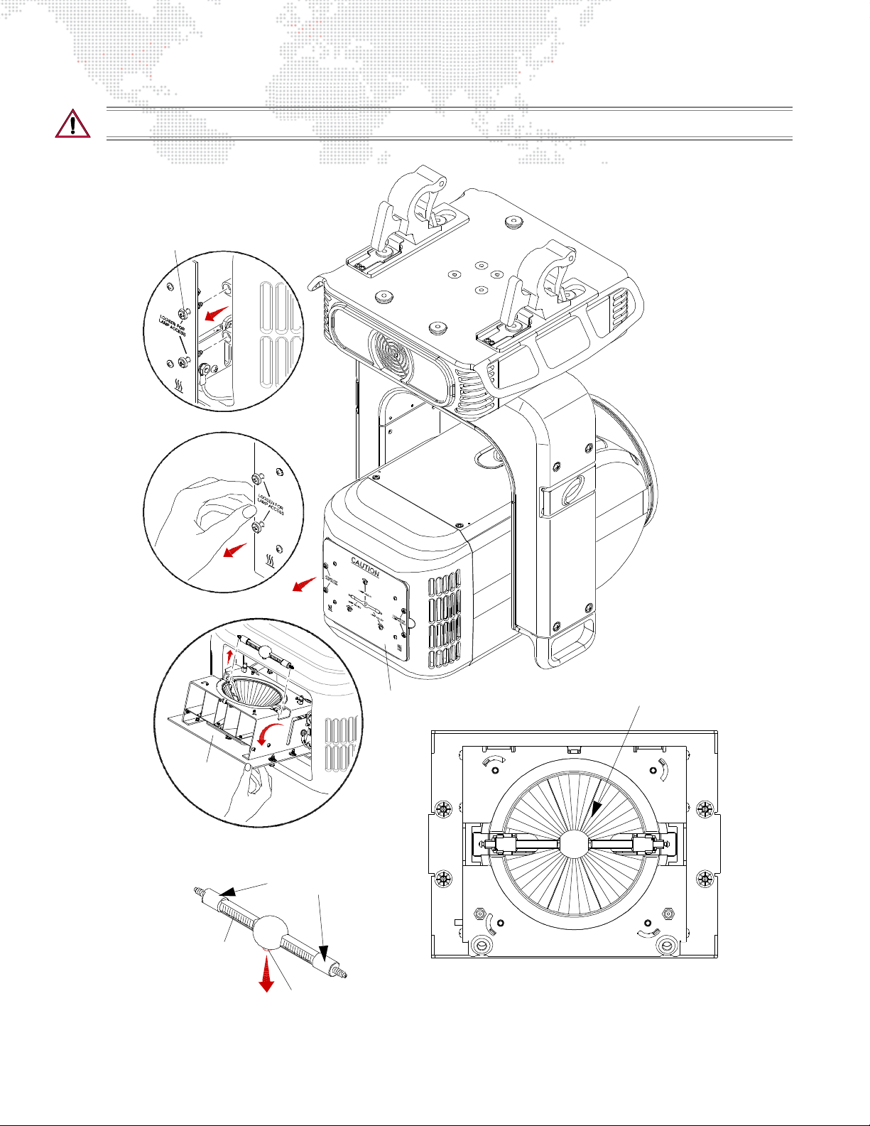
CAUTION: Allow lamp to cool before servicing.
Lamp Box
Lamp
TO P VIEW
Captive Screw
(2 per side)
Pull lamp box out
using ha ndles
Rotate lamp box
to access lamp
Lamp Box
Grip la mp at each
end to remove/install
Install lamp with nipple
facing rear of fixture
(towards reflector)
Nipple (install towards reflector)
66 BEST BOY® HP SPOT LUMINAIRE USER MANUAL
Figure 4-2: Replacing the Lamp
Page 75
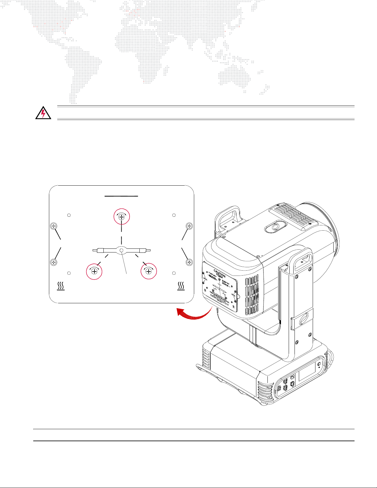
Adjusting Lamp
DO NOT OPERATE WITHOUT
IN PLACE OR WHEN LENS IS
COMPL ETE LA MP EN CL O S UR E
DAMAG ED.
RISK OF EXPOSURE TO EXCESSIVE
ULTRAVIOLET RADIATION
SOURCE DE RAYONNEMENT UV
FOR 5 MINU T ES. DISCONNECT FIX T URE BEFORE RELAMPING OR SERVICING.
NE PAS ENLEVER L’ECRAN DE
PROTECTION
DANGER: I NTENSE HEAT. AVOID CONTACT BY PERSONS AN D MA TERIALS
COUPER L’ALIM ENTATION AVANT LE DEPANN AGE
INSTALL LAM P NIPPLE TOWARD REAR OF FIXTUR E.
RISK OF FIRE: USE WIT H MAX
1500 WATT LAMP. USE ONLY A
HIGH-PRESSURE LAMP OF DOUBLE-ENDED
TYPE HTI 1500W METAL HALIDE.
DANGE R: CHALEUR IN TENSE . E VITER TOU T CONTAC T ET TE NI R TOUTE
MATIERE A L’ECART
WARNING: RISK OF POSSIBLE LAMP EXPLOSION. ALLOW HOUSING TO COOL
ATTENTION: UTILISER UNE
LAMPE 1500 WATTS DOUBLE-CLO S
TYPE HTI METAL HALIDE.
LAMP ADJUST
LAMP ADJUST LAMP ADJUST
LOOSEN FOR
LAMP ACCESS
LOOSEN FOR
LAMP ACCESS
CAUTION
After a new lamp is installed, the lamp must be aligned to optimize the beam. Adjustment controls are located on the
backcap.
Tools:
#2 Phillips screwdriver
optional
To adjust lamp:
Step 1. Power up luminaire and allow to warm up for at least ten minutes.
Step 2. Set intensity to 100%.
Step 3. Position beam on a white wall at a distance of 10' to 20'.
Step 4. At backcap, use three adjustment screws to optimize beam (Figure 4-3).
: 5/16"-1/2" telescoping gauge (http://www.mcmaster.com/#inside-micrometers/=r6gx02 - item # 2081A6)
WARNING: Backcap may be HOT during lamp operation.
Note: Be sure to reset Lamp Hours when installing a new lamp.
Figure 4-3: Adjusting the Lamp
BEST BOY® HP SPOT LUMINAIRE USER MANUAL 67
Page 76
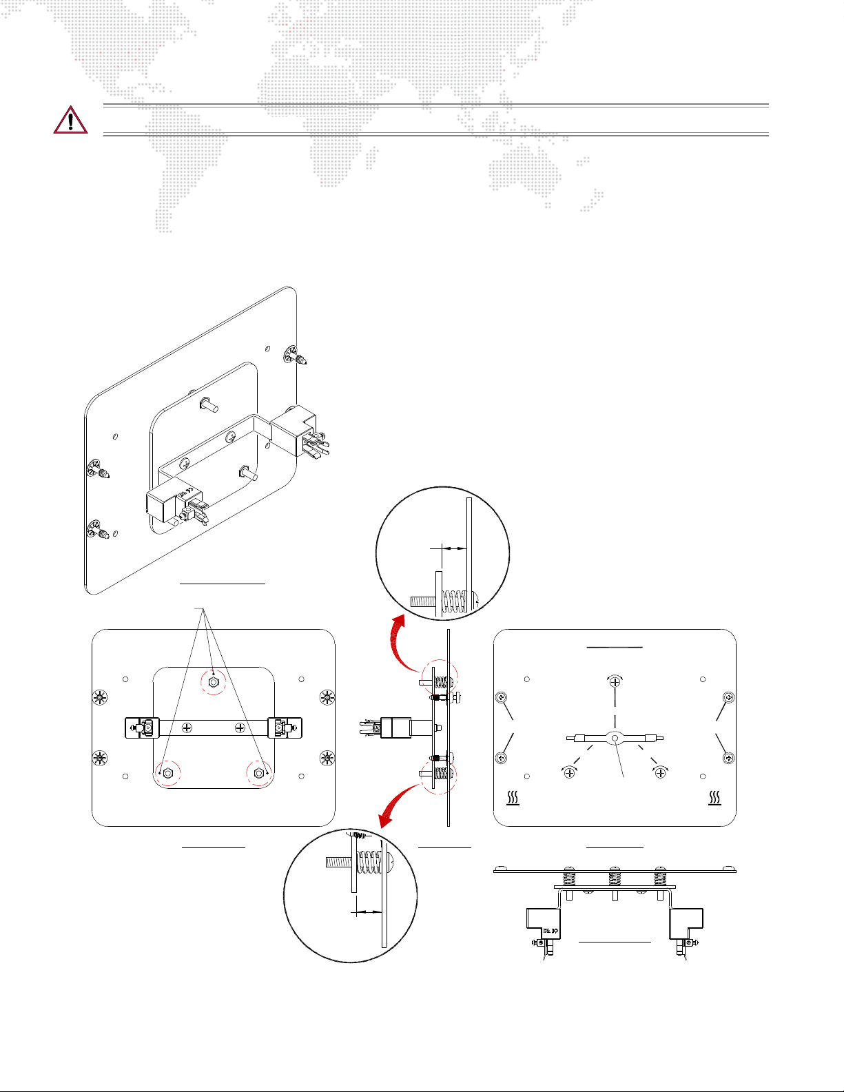
CAUTION: Allow lamp to cool before servicing.
FRONT VIEW REAR VIEWSIDE VIEW
BOTTOM VIEW
ISOMETRIC VIEW
0.343" TYP
2 PLACES
0.353"
MEASUREMENT POINTS
DO NOT OPER ATE WITH OUT
IN PLACE OR WHEN LENS IS
COMPLETE LAMP ENCLOSURE
DAMAGED.
RISK OF EXPOSURE T O EXCESSIV E
ULTRAVIOLET RADIATION
SOURCE DE RAYONNEMENT UV
FOR 5 MINUTES. DISCONNECT FIXTURE BEFORE RELAMPING OR SERVICING.
NE PAS ENLEVER L’ECRAN DE
PROTECTION
DANGER: INTENSE HEAT. AVOID CONTACT BY PERSONS AND MATERIALS
COUPER L’ALIMENTATION AVANT LE DEPANNAGE
INSTALL LAMP NIPPLE TOWARD REAR OF FIXTURE.
RISK OF FIRE: USE WITH MAX
1500 WATT LAMP. USE ONLY A
HIGH-PRESSURE LAMP OF DOUBLE-ENDED
TYPE HTI 1500W METAL HALIDE.
DANGER: CHA LEUR INTE NS E . EVITER TOUT CONTACT ET TENIR TOUTE
MATIERE A L’ECART
WARNING: RISK OF POSSIBLE LAMP EXPLOSION. ALLOW HOUSING TO COOL
ATTENTION: UTILISER UNE
LAMP E 1500 WA TTS DOU BLE-CLOS
TYPE HTI METAL HALIDE.
LAMP ADJUST
LAMP ADJUST LAMP ADJUST
LOOSEN FOR
LAMP ACCESS
LOOSEN FOR
LAMP ACCESS
CAUTION
Step 5. (Optional) Lamp alignment can be double-checked and/or adjusted by measuring the distance of the lamp
plate from the rear door.
a. First, open the lamp access door (refer to "Replacing the Lamp" on page 65).
b. Then use a telescoping gauge tool to measure the distance at three places. These should all be 0.388"
as shown in Figure 4-4. Adjust the lamp plate as necessary using the three lamp adjustment screws.
c. When finished, close lamp access door.
68 BEST BOY® HP SPOT LUMINAIRE USER MANUAL
Figure 4-4: Measuring Lamp Alignment Position
Page 77
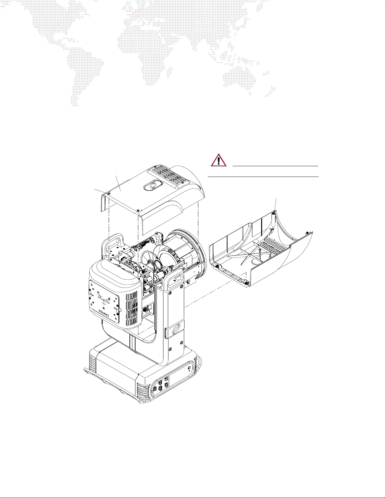
Removing Head Covers
R2 / Designer Wheel
Head Cover
R1 Head Cover
Captive
Screw (4)
CAUTION: DO NOT let covers hang by lanyards!
To access some interior head components, one or both of the Head Covers may need to be removed.
A label on the backcap indicates which wheel components the head cover provides access to.
Parts:
21.9816.0630 2 EA ASSY, HEAD COVER
Tools:
#2 Philips screwdriver
To remove Head Covers:
Step 1. At cover, loosen four captive screws (Figure 4-5). (Cover will still be secured by a safety lanyard.)
Step 2. Unclip lanyard to completely remove cover.
Step 3. Replace covers as follows:
a. Attach lanyard clip.
b. Fit cover in place.
c. Tighten four captive screws.
Figure 4-5: Removing Head Covers
BEST BOY® HP SPOT LUMINAIRE USER MANUAL 69
Page 78
Cleaning the Luminaire Exterior
Tools:
Lint-free cloth
Window cleaner
Vacuum cleaner with brush nozzle or compressed air
#2 Phillips screwdriver
To clean luminaire:
WARNING: Remove power from luminaire before this procedure.
CAUTION: Use ONLY OptiMax™ Ultra Pure Cleaning Solution to clean optical components. DO NOT use
Window Cleaner on lens!
Step 1. Remove power from luminaire.
Step 2. Using vacuum cleaner with brush nozzle or compressed air, clean dust from external components.
compressed air to clean out luminaire, DO NOT allow fans or blower to spin at high speeds, as this will
damage their bearings.
Step 3. Using window cleaner and a clean, lint-free cloth, wipe outside surface of luminaire.
DO NOT use window cleaner on lens!
If using
70 BEST BOY® HP SPOT LUMINAIRE USER MANUAL
Page 79
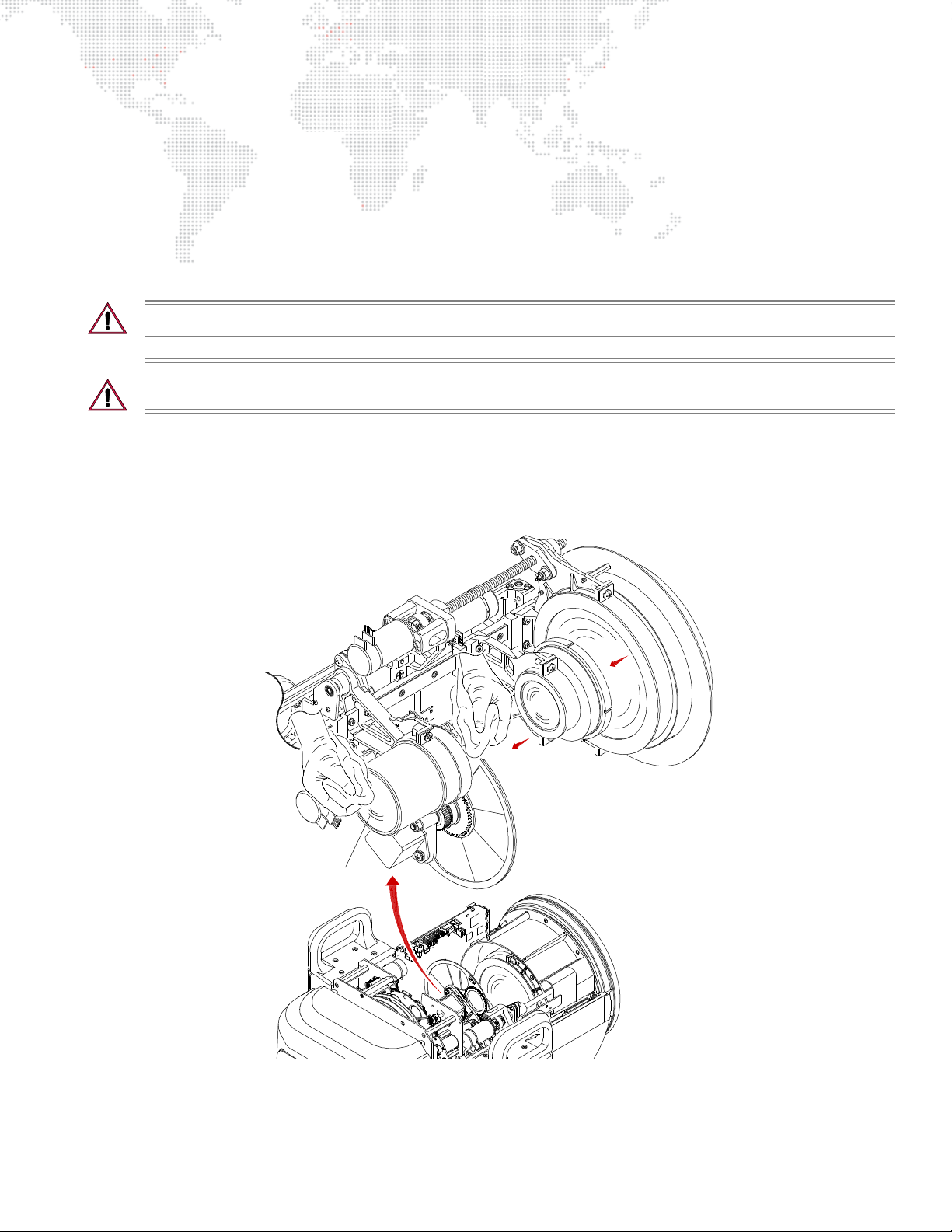
Cleaning the Lenses
ZOOM LENS ASSEMBLY DETAIL
Lenses
Tools:
(2) Micro Fiber cloths (06.6085.0001.0)
OptiMax™ Ultra Pure Cleaning Solution (06.6084.0001.0)
Cotton gloves or finger cots
#2 Phillips screwdriver
3/16" flat screwdriver
To clean lenses:
CAUTION: Use caution when handling lenses. Avoid scratching optical surfaces.
CAUTION: Use ONLY OptiMax™ Ultra Pure Cleaning Solution to clean optical components. DO NOT use
Window Cleaner on lenses! Wear cotton gloves or finger cots when handling lenses/glass.
Step 1. Apply power to luminaire and set intensity to 20%. (A beam will be necessary to see dirt and dust on the
lenses.)
Step 2. Remove R2/Designer Head Cover to access Zoom Lens Assembly. (Refer to "Removing Head Covers" on
page 69.)
Figure 4-6: Accessing Zoom Lens Assembly
BEST BOY® HP SPOT LUMINAIRE USER MANUAL 71
Page 80
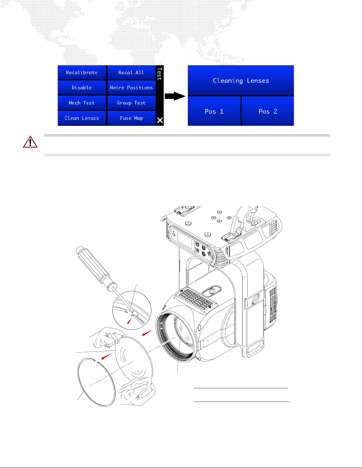
Step 3. At menu TEST screen, press "Clean Lenses." The Cleaning Lenses screen will open.
Front Glass
Retaining
Front Le ns
Notch
Ring
Note: Ensure gasket under Front Glass is not
damaged or missing before reinst alling.
Step 4. Press "Pos1" to position lenses in first cleaning configuration.
CAUTION: When cleaning, do not allow the cleaning cloth to come into contact with the lens carrier rail. The
rail has lubrication that will contaminate the cleaning cloth. Wear cotton gloves or finger cots.
Step 5. If lenses are only dusty, use Micro Fiber cloth to carefully wipe lens surfaces. If further cleaning is required,
use OptiMax™ Ultra Pure Cleaning Solution and a Micro Fiber cloth to clean.
DO NOT use window cleaner!
Step 6. At menu, press "Pos2" to position lenses in second cleaning configuration. (This will allow access to the
remaining lens surfaces.)
Step 7. As in Step 5 above, clean remaining lens surfaces and front of luminaire Front Glass (Figure 4-7).
72 BEST BOY® HP SPOT LUMINAIRE USER MANUAL
Figure 4-7: Removing Front Glass
Page 81
CAUTION: Be extremely careful when removing Retaining Ring and Front Glass in next step. The glass can
be easily chipped or cracked.
Step 8. To clean backside of Front Glass and front of Lens Group , remove Front Glass as follows:
a. Position luminaire head so that Front Glass is facing upward. (To prevent it from falling onto the floor
when the Retaining Ring is removed in the next step.)
b. Insert flat screwdriver under notch in Front Lens Retaining Ring. Carefully remove Retaining Ring.
c. Remove Front Glass and place facedown on a Micro Fiber cloth.
d. Using OptiMax™ Ultra Pure Cleaning Solution and a Micro Fiber cloth, clean both sides of Front Glass
and front of Lens Group.
DO NOT use window cleaner!
e. Ensure gasket under Front Glass is not damaged or missing.
f. Re-install Front Glass.
CAUTION: "Done" MUST BE pressed at the menu to complete the procedure. If the lens motors are left in
the cleaning configuration for too long, they may be damaged due to overheating.
Step 9. At menu, press "Done." This will free the motors and recalibrate the lenses.
Step 10. Replace Head Cover.
BEST BOY® HP SPOT LUMINAIRE USER MANUAL 73
Page 82
Cleaning Gobo, Color, and Effect Wheels
Tools:
Micro Fiber cloth (06.6085.0001.0)
OptiMax™ Ultra Pure Cleaning Solution (06.6084.0001.0)
Cotton gloves or finger cots
#2 Phillips screwdriver
To clean gobo, color and effect wheels:
CAUTION: Use ONLY OptiMax™ Ultra Pure Cleaning Solution to clean optical components. DO NOT use
Window Cleaner on gobo, color, or dimmer wheels! Wear cotton gloves or finger cots when handling optical
components.
CAUTION: The optical components are very fragile, use extreme caution when cleaning! Color gobos have
thin layers applied to one side that can be damaged if cleaned too roughly. Use caution.
WARNING: Remove power from luminaire before this procedure.
Step 1. Remove power from luminaire.
Step 2. Remove Head Covers. (Refer to "Removing Head Covers" on page 69.)
Step 3. To clean Gobos:
a. Remove all gobos. (Refer to "Replacing a Gobo in Gobo Wheel 1" on page 75.)
b. Using OptiMax™ Ultra Pure Cleaning Solution and a Micro Fiber cloth, carefully clean gobos.
DO NOT use window cleaner!
Step 4. To clean Designer Wheel:
a. Remove each filter. (Refer to "Replacing a Designer Color Filter" on page 79.)
b. Using OptiMax™ Ultra Pure Cleaning Solution and a Micro Fiber cloth, carefully clean filters.
DO NOT use window cleaner!
Step 5. To clean Color Wheels:
a. Using OptiMax™ Ultra Pure Cleaning Solution and a Micro Fiber cloth, carefully clean color wheels.
DO NOT use window cleaner!
b. Rotate wheels to access all surfaces.
Step 6. To clean Effect Wheel:
a. Using OptiMax™ Ultra Pure Cleaning Solution and a Micro Fiber cloth, carefully clean Effect Wheel.
DO NOT use window cleaner!
b. Rotate wheel to access all surfaces.
Step 7. Replace Head Covers.
74 BEST BOY® HP SPOT LUMINAIRE USER MANUAL
Page 83

Replacing a Gobo in Gobo Wheel 1
Gobo
Wheel
Locking
Tongue
1
2
3
4
5
6
Note: Some components are
shown exploded for clarity.
Tab
Alignment
Mark
Sun Gear
Magnet
Carrier Ta b
Due to the complex gear alignment, it is best to remove ALL gobos from the wheel even when replacing or swapping
only one gobo. This way all gobos can be re-installed at one time with the proper alignment. Recalibrating a single
gobo can be a difficult process.
Parts:
Standard or Custom Gobo(s), as required. (Refer to "Gobo Wheel Standard Configurations" on page 8.)
Tools:
#2 Phillips screwdriver
Cotton gloves or finger cots
WARNING: Remove power from luminaire before performing any maintenance procedures.
To replace a gobo:
Step 1. Remove power from luminaire.
Step 2. Remove R1 Head Cover. (Refer to "Removing Head Covers" on page 69.)
CAUTION: Do not touch gobos with bare fingers. Wear cotton gloves or finger cots when handling.
Step 3. Using fingers, grasp frame of each gobo and pull out of wheel (Figure 4-8). Remove ALL gobos.
Figure 4-8: Replacing a Gobo (Wheel 1)
BEST BOY® HP SPOT LUMINAIRE USER MANUAL 75
Page 84

Step 4. Re-install all gobos (making changes as necessary) by doing the following:
1
2
34
5
6
a. Rotate gobo wheel so that first position is accessible. Refer to Figure 4-9 for wheel positions.
b. Align gobo’s magnet with alignment mark on sun gear as shown in Figure 4-8.
c. Carefully insert gobo, ensuring that carrier tab goes under retaining plate (under sun gear). Press until
tongue is secured by locking tab.
d. Rotate gobo wheel to next position and install next gobo in same manner. Repeat for remaining gobos.
Step 5. When finished, rotate gobo wheel as a visual test. When properly installed, the gobo magnet for each
installed gobo should be positioned in the same approximate position as the gobo wheel is spun around.
Adjust as necessary.
Step 6. Replace Head Cover.
Figure 4-9: Gobo Wheel 1 Positions
76 BEST BOY® HP SPOT LUMINAIRE USER MANUAL
Page 85
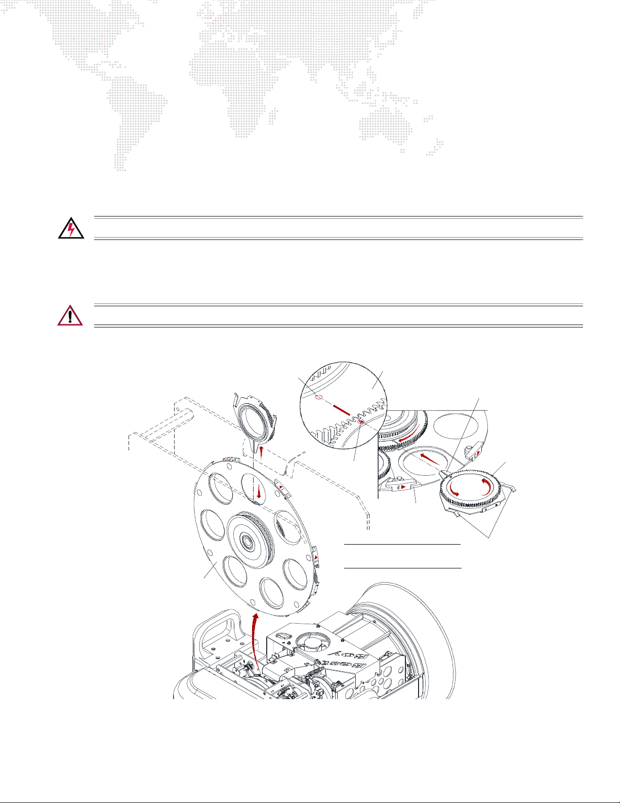
Replacing a Gobo in Gobo Wheel 2
Gobo
Wheel
Sun Gear
Locking
Tongue
1
2
3
4
5
6
Note: Some components are
shown exploded for clarity.
Tab
Alignment
Mark
Magnet
Carrier Tab
Due to the complex gear alignment, it is best to remove ALL gobos from the wheel even when replacing or swapping
only one gobo. This way all gobos can be re-installed at one time with the proper alignment. Recalibrating a single
gobo can be a difficult process.
Parts:
Standard or Custom Gobo(s), as required. (Refer to "Gobo Wheel Standard Configurations" on page 8.)
Tools:
#2 Phillips screwdriver
Cotton gloves or finger cots
WARNING: Remove power from luminaire before performing any maintenance procedures.
To replace a gobo:
Step 1. Remove power from luminaire.
Step 2. Remove R2/Designer Head Cover. (Refer to "Removing Head Covers" on page 69.)
CAUTION: Do not touch gobos with bare fingers. Wear cotton gloves or finger cots when handling.
Step 3. Using fingers, grasp frame of each gobo and pull out of wheel (Figure 4-10). Remove ALL gobos.
Figure 4-10: Replacing a Gobo (Wheel 2)
BEST BOY® HP SPOT LUMINAIRE USER MANUAL 77
Page 86
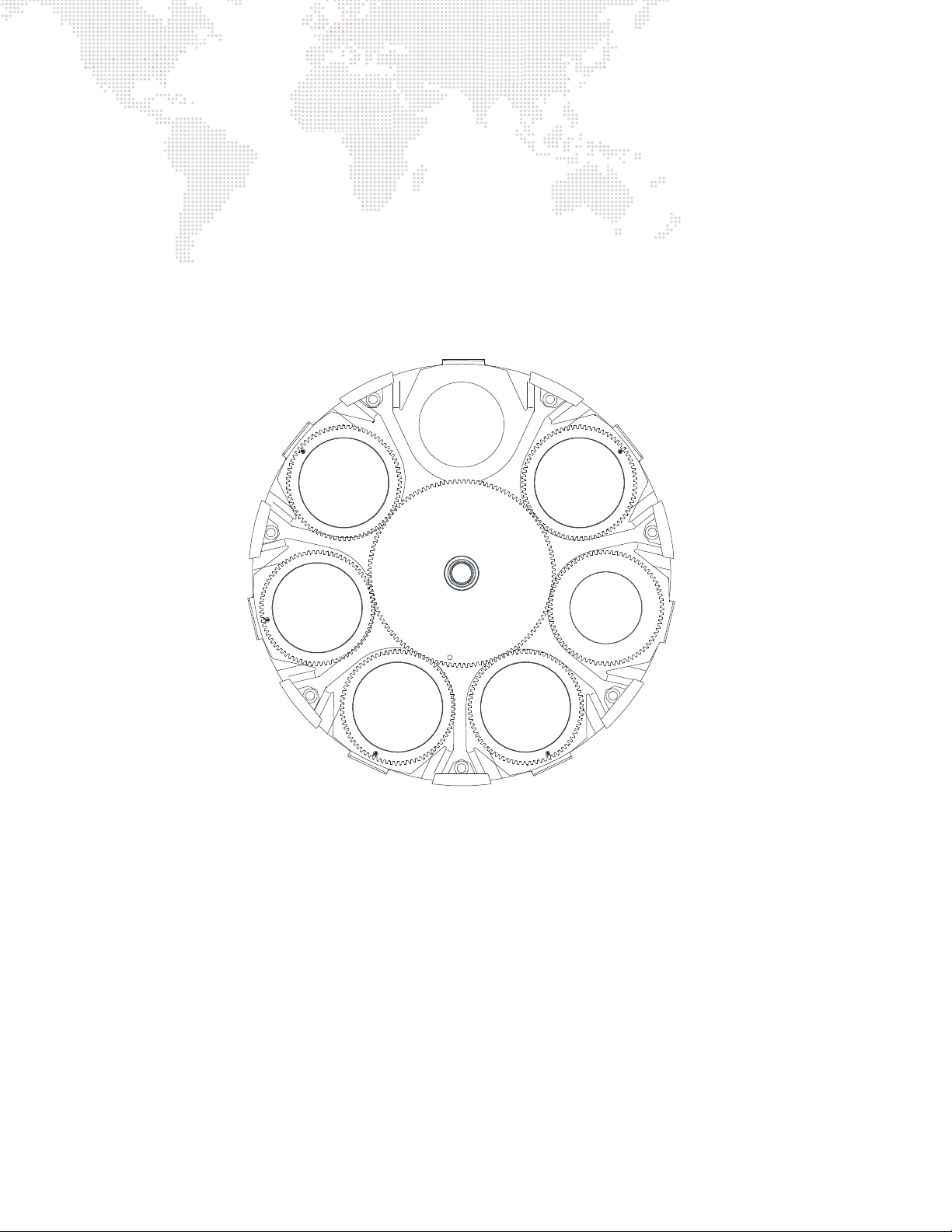
Step 4. Re-install all gobos (making changes as necessary) by doing the following:
1
2
34
5
6
a. Rotate gobo wheel so that first position is accessible. Refer to Figure 4-11 for wheel positions.
b. Align gobo’s magnet with alignment mark on sun gear as shown in Figure 4-10.
c. Carefully insert gobo, ensuring that carrier tab goes under retaining plate (under sun gear). Press until
tongue is secured by locking tab.
d. Rotate gobo wheel to next position and install next gobo in same manner. Repeat for remaining gobos.
Step 5. When finished, rotate gobo wheel as a visual test. When properly installed, the gobo magnet for each
installed gobo should be positioned in the same approximate position as the gobo wheel is spun around.
Adjust as necessary.
Step 6. Replace Head Cover.
Figure 4-11: Gobo Wheel 2 Positions
78 BEST BOY® HP SPOT LUMINAIRE USER MANUAL
Page 87
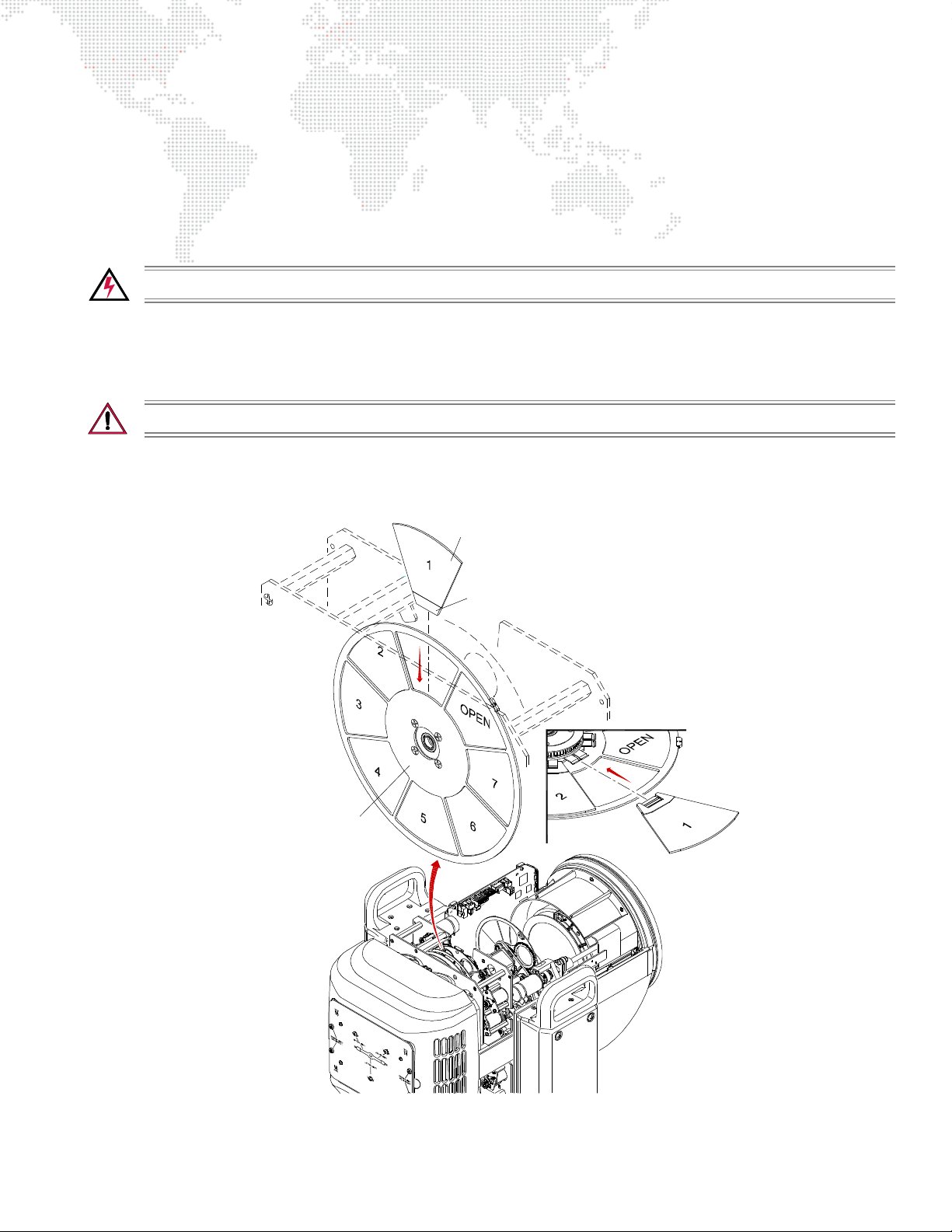
Replacing a Designer Color Filter
Designer Color Filter
Wheel Hub
Carrier
Parts:
Designer Color Filter(s), as required. (Refer to "Designer Color Wheel Standard Configuration" on page 7.)
Tools:
#2 Phillips screwdriver
Cotton gloves or finger cots
WARNING: Remove power from luminaire before performing any maintenance procedures.
To replace a designer color filter:
Step 1. Remove power from luminaire.
Step 2. Remove R2/Designer Head Cover. (Refer to "Removing Head Covers" on page 69.)
CAUTION: Do not touch color filters with bare fingers. Wear cotton gloves or finger cots when handling.
Step 3. Rotate wheel until desired designer color filter is accessible (Figure 4-12).
Step 4. Using fingers, grasp frame of color filter and pull straight out of wheel hub.
Figure 4-12: Removing a Designer Color Filter
BEST BOY® HP SPOT LUMINAIRE USER MANUAL 79
Page 88
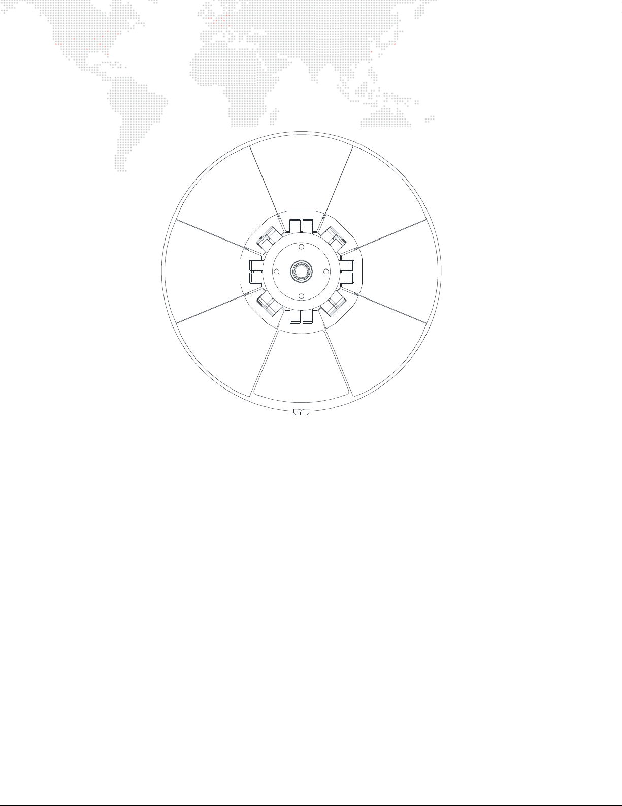
Step 5. Noting proper orientation of carrier, insert new designer color filter into position and push until carrier clicks
2
3
4
1
OPEN
7
6
5
into place. Refer to Figure 4-13 for wheel positions.
Step 6. Replace Head Cover.
Figure 4-13: Designer Color Wheel Positions
80 BEST BOY® HP SPOT LUMINAIRE USER MANUAL
Page 89

A.
TECHNICAL SPECIFICATIONS
+ BEST BOY HP SPOT LUMINAIRE
+ BEST BOY ROAD CASE
Page 90

Best Boy HP Spot Luminaire
SOURCE: HTI 1500W/D7/60 Lamp
OUTPUT: 31,000 lumens
POWER DRAW: Max. 10.5A at 208V, 8.75A at 240V. Auto-sensing voltage input range is 200-240V, 50/
60HZ
REFLECTOR: Precision glass reflector with cold mirror coating.
ZOOM RANGE: 8:1 from a tight spot of 8° to a very wide flood of 64° maintaining focus throughout.
BEAM SIZE CONTROL: In addition to the zoom optics, a mechanical iris provides continuous beam size control
for both rapid changes and smooth, timed beam angle changes.
FRAMING: Four-blade framing system featuring four independent blades mounted in two planes.
Each blade can be tilted +/- 30° and the entire frame system can be rotated +/- 60° for a
total travel of 120°.
DIMMING: Gray-scale glass dimmer for full-field dimming from 0% to 100% with accurate slow-
speed control and fast bumps.
STROBE: Servo-powered, lightning fast strobe wheel.
EFFECTS: One (1) multiplying four-facet prism, two (2) glass effects, and variable frost.
COLOR: CMY color system featuring three (3) crossfading color wheels of Cyan, Magenta, and
Yellow, plus one (1) designer wheel with seven (7) user-changeable color filters.
COLOR TEMP CONTROL: Adjustable color temperature wheel, range from 3,000K all the way up to 7,500K.
Includes an integrated minus green filter.
ROTATING GOBOS: Two (2) indexable, rotating gobo wheels with six (6) gobos per wheel. Gobos are
individually calibrated so the unit will automatically index the orientation of each gobo
regardless of initial placement. Both gobo wheels accept PRG Moiré Gobos™ for
advanced gobo rotator effects.
OPERATING TEMP: -20° to 120°F (-29° to 49°C)
CONTROL: Compatible with all PRG consoles and a wide variety of DMX512 and Art-Net consoles.
DMX CHANNELS: 45 DMX512 channels required per unit.
ETHERNET BYPASS: A relay allows Ethernet signals to pass through daisy-chained luminaires even if power is
removed.
ON-BOARD CONTROL: Built-in LCD touchscreen display allows for on-board fixture control and feedback. On-
board battery power allows for the fixture address and configurations to be set without
having to apply AC power to the luminaire.
PAN & TILT: Three-phase, high-speed servomotors. Brakes are applied when off.
RANGE: Pan - 615°, Tilt - 260°
POSITIONING: Can be mounted in any orientation.
SPACING: Hangs on 33 inch (838 mm) centers when Light Shield is extended.
Hangs on 28 inch (711 mm) centers when Light Shield is not extended.
WEIGHT: 109 lbs (49.44 kg) without hooks.
82 BEST BOY® HP SPOT LUMINAIRE USER MANUAL
Page 91
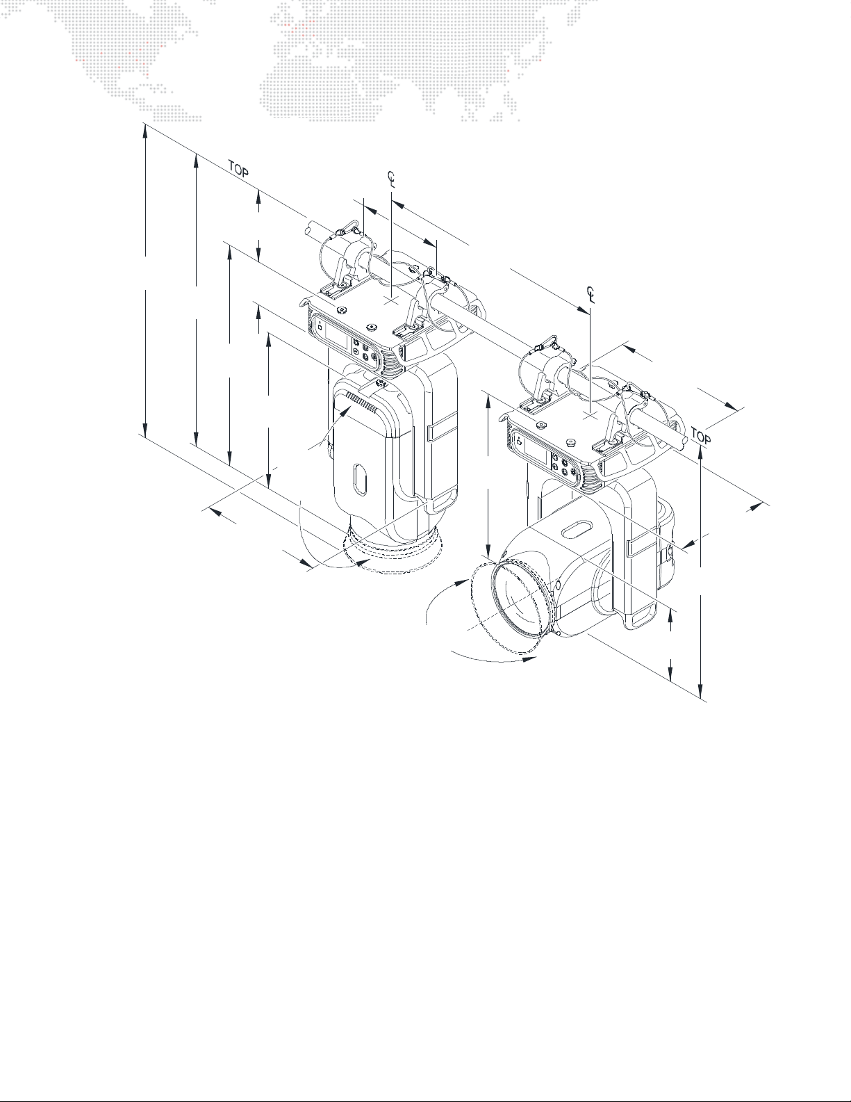
26.8"
(681 mm)
(711 mm)
28"
16.75"
(425 mm)
(290 mm)
11.4"
35.16"
(893 mm)
(991 mm )
39.0"
(147 mm)
5.78"
3.88"
(99 mm)
27.0"
(686mm)
(574 mm)
22.6"
(473 mm)
18.64"
(486 mm )
19.15"
12.5"
(318 mm)
32.43"
(824 mm)
(724 mm)
28.5"
*(838 mm)
*33"
*31.6"
*(80 3 mm)
*(1054 mm)
*41.5"
*31. 5"
*(800 mm)
* Dimensions with Light Shield extended.
BEST BOY® HP SPOT LUMINAIRE USER MANUAL 83
Page 92
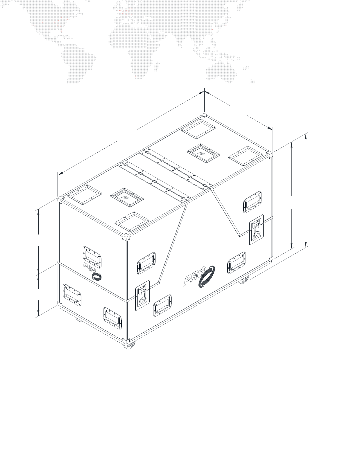
Best Boy Road Case
52"
(1321 mm)
(533 mm)
21"
12.8"
(325 mm)
(610 mm)
24"
(859 mm)
33.8"
(1003 mm)
39.5"
EMPTY WEIGHT: 171 lbs (77.56 kg)
LOADED WEIGHT: 389 lbs (176.45 kg)
84 BEST BOY® HP SPOT LUMINAIRE USER MANUAL
Page 93

B.
GLOSSARY
This glossary provides useful terms associated with operating the Best Boy HP Spot Luminaire.
Page 94

Glossary of Terms
8-Bit DMX
The universally accepted lighting control protocol in the entertainment industry. A console uses this protocol to
control specific devices in a lighting system. A DMX512 channel packet is eight bits of absolute parameter data. 8-bit
refers to the resolution of the signal: 256 step resolution, providing channel values from 0 through 255. A DMX512
data packet is a group of 512 data channels.
16-Bit DMX
To smooth out the movement of automated luminaires, the industry has adopted 16-bit DMX. This is not a change to
the DMX512 specification, rather a change in the way luminaires and consoles treat DMX512 information. In practice,
16-bit DMX adds a DMX512 channel each to pan and tilt - pan coarse, pan fine, tilt coarse, tilt fine, instead of just pan
and tilt. The console and luminaire combine these levels and increase the resolution of pan and tilt from 256 steps to
a theoretical maximum 65,536 steps at the console level, resulting in the ability to position the luminaire more
accurately.
Address
A numerical "name" given to a device on a DMX512 line indicating which of 512 possible channels it will respond to.
Align (lamp)
The process of adjusting the lamp within the reflector to obtain the desired output quality of the beam.
Arc Lamp
A type of lamp which creates light by forming an arc of electricity. Brightness is achieved by including gasses and
metals within the envelope of the lamp which dissolve and give off a bright light. Arc lamps must be dimmed
mechanically because electrical dimming will extinguish the arc.
Art-Net
Protocol for sending DMX512 data over IP networks.
Attribute
An individual controllable aspect of a luminaire: pan, tilt, color, etc. Also known as "parameter."
Beam
1) The size, shape and sharpness of image of the light beam as projected on stage.
2) A function of the luminaire related to the size, shape, and sharpness of the light beam, specified by beam and
edge data, and use of gobos (patterns) as required.
Blade
One of the four components of the Framing mechanism used to mask off certain areas of the beam’s output.
Channel
A control reference which collects a device’s associated thumbwheel address(es) (device, lamp power, etc.) and maps
them to a single selectable number. Channels are assigned via the patch setup. (Also referred to as a "Control
Channel.")
Console Timing
Time value in seconds or minutes applied to an entire cue.
CMY
Acronym for "Cyan, Magenta, and Yellow."
86 BEST BOY® HP SPOT LUMINAIRE USER MANUAL
Page 95

DMX512
Digital multiplexing; an industry standard protocol. 8-bit protocol with a maximum of 256 steps of resolution per
channel. Maximum of 512 controllable channels per DMX data stream.
DMX512 Cable
Industry standard cable consists of two twisted pair and a shield, and 5-pin XLR style connectors.
The pin out is: pin 1 = common (shield), pin 2 = data -, pin 3 = data +.
The second pair (pins 4 & 5) may be used for a secondary data link.
DMX512 Universe
A group of up to 512 DMX channels. Consoles may have more than one universe, usually labeled in groups of 512.
Douse
To de-energize a luminaire lamp. (Douse is unrelated to intensity states.)
Ethernet
Networking technology used to connect local area networks (LANs) via CAT5 cable or wireless.
Fixture Orientation
Based on the direction the pigtail points as it exits the fixture.
Flipped Focus
When one or more fixtures inadvertently move differently from others in the system.
Focus
The point to which the light beam is directed. Also, a function of the luminaire related to the direction of the beam as
specified by pan and/or tilt data.
Framing
A device/function of the luminaire which can be used to mask off certain areas of the beam’s output.
Gobo
A removable piece of glass or metal which contains a pattern used to create backgrounds or textures when projected
onto scenery or cycloramas. Gobos typically contain geometrical shapes or natural elements such as fire, stars, or
leaves.
Gobo, Moiré
See
Moiré Gobo
.
Hard Reset
Restarts luminaires and reloads operating system and cue data.
Home Position
Pan and Tilt values at 50%. Also called “Zero Position” or a "50/50" cue or group.
Indexing
A function of a rotating gobo mechanism.
Intensity
A value placed on the relative brightness of a lighting fixture; 100% is considered "full," and 0% is considered "out."
Iris
A motor controlled mechanism which is used to adjust the beam diameter.
BEST BOY® HP SPOT LUMINAIRE USER MANUAL 87
Page 96

Lamp
Light source consisting of filament or electrodes, base, and envelope or "bulb."
Luminaire Calibration
The process of a luminaire finding its end stops for all parameters.
Macro
A pre-defined sequence that allows for quick and easy control of luminaire functions such as iris, zoom, framing, and
more.
Moiré Gobo
A gobo that has two pieces of glass wherein one is fixed and the other rotates. Since the two pieces of glass are very
close together, it creates an interesting interference effect (which is referred to as the "moiré").
Palette
Term for groups of groups; i.e. all the color groups would be considered the Color Palette, all the beam groups would
be the Beam Palette, etc.
Pan
The movement of the luminaire around the axis of the yoke.
Parameter
An individual controllable aspect of a luminaire: pan, tilt, color, etc. Also known as "Attribute."
Patch
The act of assigning a DMX512 channel to a control channel on a console.
Reply
Digital data signals transmitted from each luminaire to the console. Only one luminaire may transmit at a time, in
response to a request from the console.
Signal
Control protocol from a lighting console or interface.
Shutter
See
Framing.
Splitter (Isolator)
Device used to optically isolate and split a DMX512 signal.
Note: A DMX "two-fer" cannot be used to divide a signal.
Start
To energize a luminaire arc lamp (applies to arc-lamp luminaires only).
Strobe
A special lighting effect which produces multiple rapid bursts of high intensity light.
Terminate/Termination
Termination refers to the dampening of DMX signal at the end of the transmission line. Termination is created by
placing a 100 ohm resistor between pins 2 and 3 of the DMX line. Often, there is a switch on DMX devices to do this
internally. If not, a terminator is provided in the form of an XLR connector with the proper resistor between pins 2 and
3 to be placed in the DMX Thru port on the device.
Tilt
The movement of the luminaire around the axis of the tilt tube.
88 BEST BOY® HP SPOT LUMINAIRE USER MANUAL
Page 97

Time
Control of the duration of the change of the variable parameters of some automated luminaires and other devices in a
lighting system.
Timing Channel
A Timing Channel is used in lieu of cue fade rate to determine the time it will take a luminaire to move from one setting
to another. For example, a cue in which a luminaire pans from one side of stage to the other may look "steppy" if cue
fade rate is used, because of the nature of the DMX512 signal. To overcome this, a timing channel allows the luminaire
to calculate the move "in time," effectively smoothing out the movement.
Zero Position
Pan and Tilt values at 50%. Also called "Home Position" or a "50/50" cue or group.
Zoom Table
Allows the fixture to maintain sharp focus on an image throughout the zoom range. (Note that zoom tables are
sensitive to throw distance. For this reason, a variety of zoom table versions are available for use with different
throws.)
BEST BOY® HP SPOT LUMINAIRE USER MANUAL 89
Page 98

Notes
90 BEST BOY® HP SPOT LUMINAIRE USER MANUAL
Page 99

Best Boy® HP Spot Luminaire User Manual
Version as of: March 25, 2015
PRG part number: 02.9817.0001
Page 100

Production Resource Group, LLC
Dallas Office
8617 Ambassador Row, Suite 120
Dallas, Texas 75247
www.prg.com
 Loading...