

Page 1

SOFTWARE VERSION 2.1
WWW.PRG.COM
AUTOPAR® WASH LUMINAIRE
USER MANUAL
Page 2

AutoPar®, Bad Boy®, PRG Series 400®, Mbox Extreme®, V676®, Virtuoso®, Virtuoso® DX, Virtuoso® DX2, and VL6C+™
All other brand names which may be mentioned in this manual are trademarks or registered trademarks of their respective companies.
This manual is for informational use only and is subject to change without notice. Please check www.prg.com for the latest version.
PRG assumes no responsibility or liability for any claims resulting from errors or inaccuracies that may appear in this manual.
are trademarks of Production Resource Group, LLC, registered in the U.S. and other countries.
AutoPar® Wash Luminaire User Manual
Version as of: November 8, 2010
PRG part number: 02.9802.0001.21
Production Resource Group
Dallas Office
8617 Ambassador Row, Suite 120
Dallas, Texas 75247
www.prg.com
AutoPar® Wash Luminaire User Manual
©2006-2010 Production Resource Group, LLC. All Rights Reserved.
Page 3
FOREWORD
Compliance Notice
This device complies with Part 15 of the FCC rules. Operation is subject to the following two conditions: 1) This device
may not cause harmful interference, and 2) This device must accept any interference received, including interference
that may cause undesired operation.
Conforms to:
UL STD 1573
Certified to:
CAN/CSA STD E598-1
CAN/CSA STD E598-2-17
Safety Notice
It is extremely important to read ALL safety information and instructions provided in this manual and any
accompanying documentation before installing and operating the products described herein. Heed all cautions and
warnings during installation and use of this product.
Safety symbols used throughout this manual are as follows:
CAUTION advising of potential damage to product.
WARNING advising of potential injury or death to persons.
GENERAL INFORMATION PERTAINING TO PROTECTION AGAINST ELECTRICAL SHOCK, FIRE, EXPOSURE TO
EXCESSIVE UV RADIATION, AND INJURY TO PERSONS CAN BE FOUND BELOW.
WARNING: INSTRUCTIONS FOR CONTINUED PROTECTION AGAINST FIRE
1) PRG luminaires have been designed for use only with specific lamps. Note lamp type before replacing. Installing
another type of lamp may be hazardous.
2) PRG luminaires may be mounted on any type of surface as long as mounting instructions are followed. See
instructions detailed in this manual.
3) Replace fuses with same type and rating only.
4) Minimum distance from head to any flammable object is 2m.
WARNING: INSTRUCTIONS FOR CONTINUED PROTECTION AGAINST ELECTRICAL SHOCK
1) PRG luminaires are designed for dry locations only. Exposure to rain or moisture may damage luminaire.
2) Disconnect power before servicing any PRG equipment.
3) Servicing to be performed by qualified personnel only.
WARNING: INSTRUCTIONS FOR CONTINUED PROTECTION AGAINST EXPOSURE TO EXCESSIVE ULTRAVIOLET RADIATION
1) PRG luminaires may use an HID type lamp which produces UV radiation. DO NOT look directly at lamp.
2) It is hazardous to operate luminaires without complete lamp enclosure in place or when lens is damaged. Lenses
or UV shields shall be changed if they have become visibly damaged to such an extent that their effectiveness is
impaired.
AUTOPAR® WASH LUMINAIRE USER MANUAL I
Page 4

WARNING: INSTRUCTIONS FOR PROTECTION AGAINST INJURY TO PERSONS
1) Exterior surfaces of the luminaire will be hot during operation. Use appropriate safety equipment (gloves, eye
protection, etc.) when handling and adjusting hot equipment and components. Service and maintenance should
be performed only by qualified personnel as determined by the high pressure lighting fixture manufacturer.
2) Arc lamps generate intense heat. Disconnect power and allow lamp to cool for 15 minutes before relamping.
3) Arc lamps emit ultraviolet radiation which can cause serious skin burn and eye inflammation. Additionally, arc
lamps operate under high pressure at very high temperatures. Should the lamp break, there can exist a danger of
personal injury and/or fire from broken lamp particles being discharged.
4) The lamp shall be changed if it has become damaged or thermally deformed.
5) Wear eye protection when relamping.
6) If lamp is touched with bare hands, clean lamp with denatured alcohol and wipe with lint-free cloth before
installing or powering up the luminaire.
7) Serious injury may result from the generation of ozone by this lamp system. A proper means of venting must be
provided.
II AUTOPAR® WASH LUMINAIRE USER MANUAL
Page 5
Notes de sécurité
Avant de procéder à l’installation des produits décrits dans ce guide et de les mettre en marche, il est extrêmement
important de lire TOUS les renseignements et TOUTES les directives de sécurité contenues dans ce guide ainsi que
toute documentation jointe. Tenir compte de tous les avertissements et suivre toutes les précautions pendant
l’installation et l’utilisation de cet appareil.
Les symboles de sécurité utilisés dans ce guide sont les suivants :
ATTENTION Ce symbole annonce que l’appareil risque d’être endommagé.
AVERTISSEMENT Ce symbole annonce qu’il y a risque d’accident grave ou
même fatal.
CETTE SECTION CONTIENT DES INFORMATIONS GÉNÉRALES POUR SE PROTÉGER CONTRE LES DÉCHARGES
ÉLECTRIQUES, LES INCENDIES, L’EXPOSITION EXCESSIVE AUX RAYONS UV ET TOUT AUTRE ACCIDENT
POUVANT ENTRAÎNER DES BLESSURES.
AVERTISSEMENT: Risque d’ explosion.
1) Le service et le maintenance ne devront être assurés que par des personnes qualifiées comme precisé par le
frabricant des lampes à haute pression.
2) Des vêtement de protection et les procédures précisées dans le manuel du frabricant doit être fournies.
AVERTISSEMENT: Réglage des lampes
1) Chaleur intense. Débrancher le matériel et laisser refroidir pendant 15 minutes avant de rallumer.
2) Risque l’incendie. N’utilise que des METAL HALIDE MSR 700 Watt G 22 Base.
AVERTISSEMENT: DIRECTIVES POUR SE PROTÉGER CONTRE UNE EXPOSITION EXCESSIVE AUX RAYONS
UV
1) Risque d’explosion en cas de radiation ultraviolet imprantes.
2) Ne pas intervener en l’absence de confinement de la lampe en place ou quand la lentille est abîmée.
AVERTISSEMENT: DIRECTIVES POUR SE PROTÉGER CONTRE LES ACCIDENTS POUVANT ENTRAÎNER DES
BLESSURES
1) Chaleur intense. Eviter tout contact avec des personnes ou des tissues. Attention, de graves blessures peuvent
résulter de production d’ozone par cette lampe. Un système de ventilation adapté doit être fournies
2) La température de surface = 300.c
La temperature de l’ambiance = 50.c
3) Ne convient pas pour un usage résidential.
4) Utilisable seulement dans les locaux secs
AUTOPAR® WASH LUMINAIRE USER MANUAL III
Page 6

Revision History
This manual has been revised as follows:
Version Release Date Notes
BASIC February 8, 2006 Software version 1.0. Initial release.
A March 20, 2006 Revised “Aligning Lamp” p. 13
B September 11, 2007 Updated menu system operation to software version 2.0
C November 8, 2010
Changed software version to 2.1 and updated book format. (No change
to technical information.)
IV AUTOPAR® WASH LUMINAIRE USER MANUAL
Page 7

TABLE OF CONTENTS
Introduction
About This Manual........................................................................................................................................................................ 1
Additional Documentation............................................................................................................................................................ 1
Customer Service......................................................................................................................................................................... 2
Chapter 1. Description
Features
Overview....................................................................................................................................................................................... 4
Components
Included Items.............................................................................................................................................................................. 5
Replacement Items and Accessories........................................................................................................................................... 5
Major Components and Controls ................................................................................................................................................. 6
Chapter 2. Installation
Power and Data Cabling Requirements
Power ........................................................................................................................................................................................... 8
Data .............................................................................................................................................................................................. 8
Male Termination Connector............................................................................................................................................... 10
Installation Procedure
Hanging the Luminaire ............................................................................................................................................................... 11
Floor Mounting the Luminaire..................................................................................................................................................... 13
Connecting Data and Power ...................................................................................................................................................... 13
Power Up Procedure
Powering Up the Luminaire........................................................................................................................................................ 14
Programming a Starting Address............................................................................................................................................... 15
Programming Starting Address Without Calibrating .................................................................................................................. 15
Configuring Lamp Operation and Other Options ....................................................................................................................... 15
Chapter 3. Operation
Menu System
Overview..................................................................................................................................................................................... 18
Menu Functions.......................................................................................................................................................................... 19
DMX512 Operation
Channel Mapping ....................................................................................................................................................................... 20
Control Channel Functions......................................................................................................................................................... 21
Luminaire Timing
Timing Channel Information ....................................................................................................................................................... 22
Chapter 4. Troubleshooting and Maintenance
Troubleshooting
Error Messages........................................................................................................................................................................... 28
Troubleshooting Guide ............................................................................................................................................................... 29
Routine Maintenance
Replacing Lamp ......................................................................................................................................................................... 30
Aligning Lamp............................................................................................................................................................................. 31
Replacing Front Lens.................................................................................................................................................................. 32
Installing a Color Gel .................................................................................................................................................................. 33
Cleaning the Luminaire............................................................................................................................................................... 34
AUTOPAR® WASH LUMINAIRE USER MANUAL V
Page 8

Appendix A. Technical Specifications
AutoPar Wash Luminaire ............................................................................................................................................................ 36
VI AUTOPAR® WASH LUMINAIRE USER MANUAL
Page 9

INTRODUCTION
About This Manual
This manual provides necessary information regarding product safety, installation, and operation for the following
PRG equipment:
+ AutoPar® Wash Luminaire (20.9802.0001)
The instructions apply to AutoPar software version 2.1.
Familiarizing yourself with this information will help you get the most out of your PRG product.
WARNING: It is important to read ALL accompanying safety and installation instructions to avoid damage to
the product and potential injury to yourself or others.
Additional Documentation
For extended service information, refer to the following PRG manual:
+ AutoPar Wash Luminaire Service Manual (02.9802.0010)
For more information regarding DMX512 systems, refer to the DMX512/1990 & AMX 192 Standards publication
available from United States Institute for Theatre Technology, Inc. (USITT).
USITT
6443 Ridings Road
Syracuse, NY 13206-1111 USA
1-800-93USITT
www.usitt.org
AUTOPAR® WASH LUMINAIRE USER MANUAL 1
Page 10

Customer Service
For technical assistance, contact the PRG International Service Center or contact your nearest PRG office. Contact
information for all PRG office locations can be found on our website at: www.prg.com/about-us/locations/
PRG Dallas (International Service)
8617 Ambassador Row, Suite 120
Dallas, Texas 75247 USA
Phone: 214.630.1963
Fax: 214.630.5867
Service Fax: 214.638.2125
Service Email: [email protected]
For additional resources and documentation, please visit our website at: www.prg.com
2 AUTOPAR® WASH LUMINAIRE USER MANUAL
Page 11

1.
DESCRIPTION
This chapter contains descriptions of luminaire features, components, and accessories.
+
FEATURES
+ COMPONENTS
Page 12
FEATURES
Overview
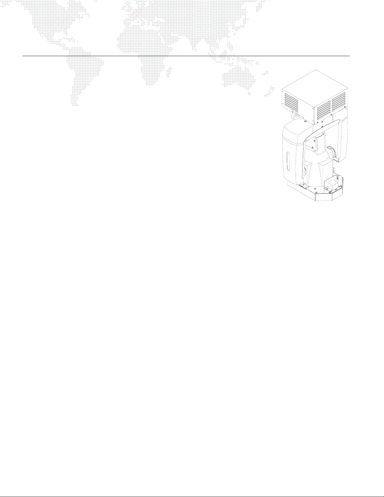
The AutoPar Wash Luminaire from PRG Lighting is a compact, lightweight fixture which
incorporates PAR 56 illumination with the dynamic features of an automated luminaire.
The AutoPar luminaire features a powerful 700 watt arc lamp, an integrated ballast with
power factor correction and a moving yoke. Four interchangeable front lenses provide
a wide range of beam options, while a standard gel frame allows for color
customization. A programmable rotating front lens assembly provides smooth rotation
of the front lens within a 200° range. The unit contains a cold mirror dichroic coated
reflector and a UV filter, which produce a cool, safe beam of light.
The AutoPar wash luminaire can be mounted in any orientation and easily controlled by
any DMX512-compatible console. Two Mega-Claw truss hooks are included for quick,
safe installation.
Features:
+ 700W arc lamp
+ Programmable rotating front lens assembly.
+ Smooth, timed continuous pan and tilt motion by way of three-phase stepper motors.
+ Integrated electronic ballast with universal input and power factor correction.
+ Modified parabolic, multifaceted reflector finished with a metal cold mirror dichroic coating.
+ Internal coated UV filter which rejects greater than 99% of ultra-violet radiation.
+ Four heat resistant, molded borosilicate glass lenses included: Very Narrow Spot, Narrow Spot,
8-Row Lenticular, and 12-Row Lenticular.
+ Gel frame holder which allows tool-free replacement of standard color gels.
+ Forced-air cooling for ballast.
+ Control by DMX512.
+ Remote start and douse from console.
+ Self-test functions.
4 AUTOPAR® WASH LUMINAIRE USER MANUAL
Page 13
COMPONENTS
Included Items
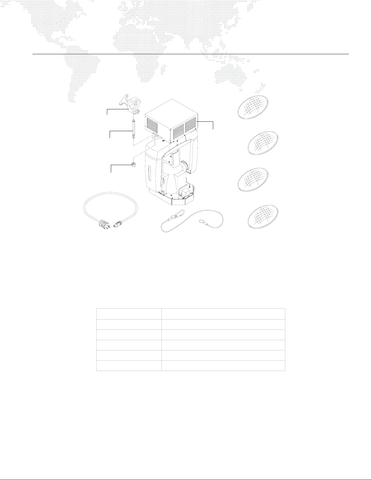
The following illustration shows all items included with the luminaire:
Mega Claw Hook (2)
Clamp Mount (2)
Flex Top Lock Nut (2)
Power Cable
AutoPar
Luminaire
Safety Cable
Very Narrow Spot Lens
Narrow Spot Lens
8-Row Lenticular Lens
12-Row Lenticular Lens
Figure 1-1: AutoPar Wash Luminaire Included Items
Replacement Items and Accessories
The following items can be ordered from PRG. (Please order by PRG part number.)
PRG P/N Accessory
10.9802.0010 Clamp Mount
23.9623.0177 DMX Termination Connector
55.6840.0001 Mega-Claw Truss Hook (Round and Square)
55.6841.0001 Mega-Claw Truss Hook (2" Round Tube)
71.2566.0700.0 MSR 700W LAMP
AUTOPAR® WASH LUMINAIRE USER MANUAL 5
Page 14
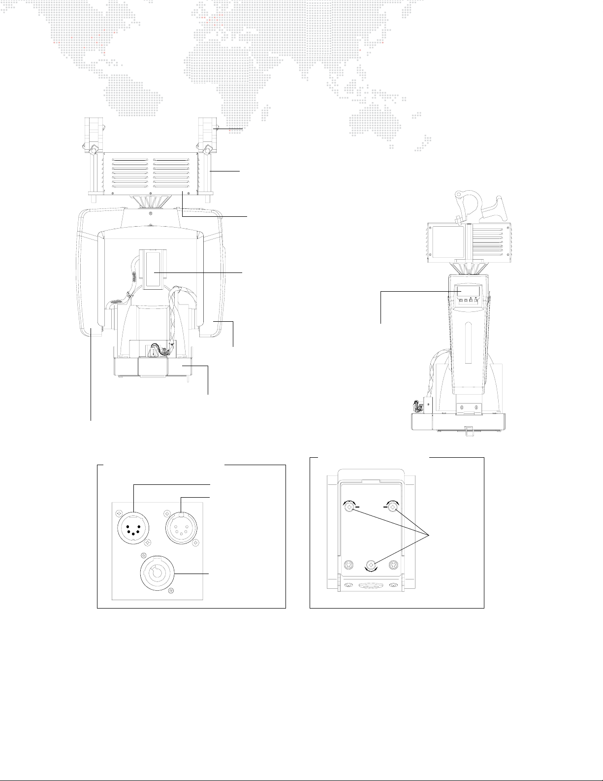
Major Components and Controls
The following illustration shows the external luminaire components and controls.
Mega-Claw Truss Hook (2) Allows luminaire to be mounted on truss pipe.
(May be replaced with other truss hook types.)
Clamp Mount (2) Provides attachment point for truss
hooks or other mounting hardware.
Upper Enclosure Houses power supply, ballast, and
provides Data In and Thru, and AC
power connections (see detail below).
Backcap Assembly Provides beam adjustment
controls and access to lamp for
replacement (see detail below).
Menu Display Used to configure luminaire
Yoke Assembly Houses Master Control Board
(MCB) and Menu Display.
FRONT VIEW
Lens Rotation Assembly Mechanism for rotating front lens.
DMX address and other
options. Also, provides
status information.
ENTERMENU
Yoke Leg Cover Protects interior components. (Do not operate with covers removed.)
Upper Enclosure Connections
Data In
Data Thru
Neutrik® AC
Power Connector
Figure 1-2: AutoPar External Components and Controls
Lamp Adjustment Controls
CAUTION
LAMP ADJUST
DANGER: INTENSE HEAT.
DISCONNECT FIXTURE AND ALLOW
HOUSING TO COOL FOR
15 MINUTES BEFORE RELAMPING.
RISK OF FIRE. USE ONLY
MSR 700 WATT METAL HALIDE
LAMP, G22 BASE.
RELAMP
x2
LAMP ADJUST
RELAMP
x2
BACKCAP REAR VIEW
SIDE VIEW
Lamp
Adjust
Screws
6 AUTOPAR® WASH LUMINAIRE USER MANUAL
Page 15

2.
INSTALLATION
This chapter contains instructions for installing the luminaire. It includes connecting power and data,
along with instructions for powering up the luminaire for the first time and addressing it within your
system.
+
POWER AND DATA CABLING REQUIREMENTS
+ INSTALLATION PROCEDURE
+ POWER UP PROCEDURE
Page 16
POWER AND DATA CABLING REQUIREMENTS
Power
The AutoPar Wash Luminaire requires standard AC power distribution from 100-240 VAC, 50/60 Hz, 10 Amps
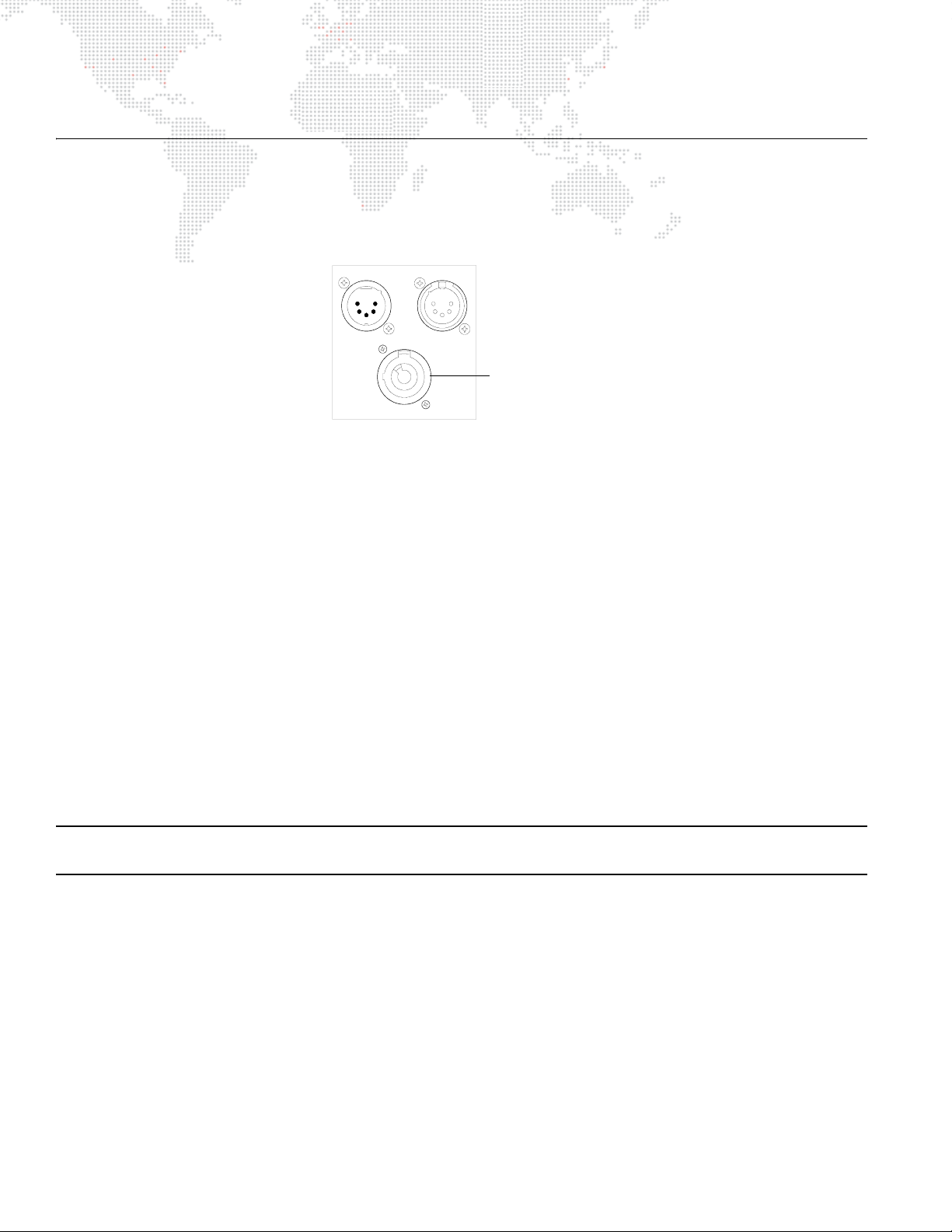
maximum. The upper enclosure provides a Neutrik® connector for power input. (Power cable not supplied.)
Neutrik AC
Power Connector
Figure 2-1: Power Input Connector
Data
The AutoPar Luminaire is equipped with two, 5-pin XLR connectors for DATA IN and DATA THRU (out) applications.
DATA IN requires a 5-pin, female XLR connector and DATA THRU requires a 5-pin, male XLR connector. When
purchasing or constructing data cables, it is important that not only the correct cable type be used, but also quality
cable to ensure a reliable DMX512 system. Your cabling should meet the following USITT DMX specification
requirements:
+ Suitable for use with EIA485 (RS485) operation at 250k baud.
+ Characteristic impedance 85-150 ohms, nominally 120 ohms.
+ Low capacitance.
+ Two twisted pairs.
+ Foil and braid shielded.
+ 24 AWG minimum gauge for runs up to 1000 feet (300m).
+ 22 AWG minimum gauge for runs up to 1640 feet (500m).
Note: Microphone type cables and other general purpose, two-core audio or signal cables are not suitable for use
with DMX512.
8 AUTOPAR® WASH LUMINAIRE USER MANUAL
Page 17
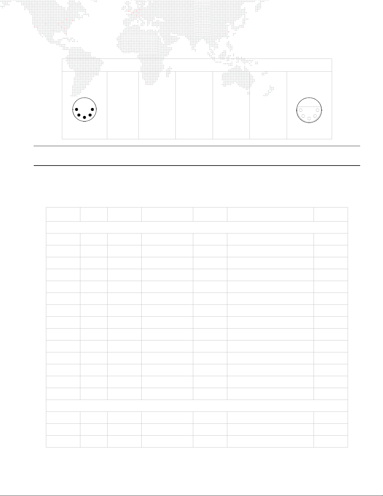
The XLR 5-pin connectors should be wired as follows:
Pin/Wire Code to XLR Connectors
Data Thru
Cable Pinout
1
2
4
3
Male Conn
5
Pin 1
Foil &
Braided
Shield
Pin 2
1st
conductor
of 1st
twisted pair
Data (-)
Pin 3
2nd
conductor
of 1st
twisted pair
Data (+)
Pin 4
1st
conductor
of 2nd
twisted pair
Data (-)
Pin 5
2nd
conductor
of 2nd
twisted pair
Data (+)
Data In
Cable Pinout
5
4
2
3
Female Conn
1
Note: Refer to the USITT Recommended Practice for DMX512 guide for additional information regarding DMX512
systems. See "Additional Documentation" on page 1.
Recommended Cable Types/Manufacturers
These are only a few of the suitable cable types. Any quality EIA485, twisted pair, 120 ohm, shielded cable will also
work.
Ty pe P ai rs
ZΩ
∗
Belden Cables
1215A 2 150 PVC 26 IBM Type 6 Office cable 75
1269A 2 100 PTFE 22 (Solid) High Temp, Plenum cable 200
Jacket AWG Use Temp (F)
8102 2 100 PVC 24 UL2919 80
8132 2 120 PVC 28 UL2919 80
8162 2 100 PVC 24 UL2493 60
82729 2 100 PTFE 24 High Temp, Plenum cable 200
88102 2 100 PTFE 24 High Temp, Plenum cable 200
89696 2 100 PTFE 22 High Temp, Plenum cable 200
89729 2 100 PTFE 24 High Temp, Plenum cable 200
89855 2 100 PTFE 22 High Temp, Plenum cable 200
9729 2 100 PVC 24 UL2493 60
9804 2 100 PVC 28 UL2960 60
9829 2 100 PVC 24 UL2919 80
9842 2 120 PVC 24 UL2919 80
Proplex Cables
PC224P 2 110 Polyurethane 22 Heavy Duty and Portable 105
PC224T 2 110 PVC 22 UL2464 105
PC226T 3 110 PVC 22 UL2464
* Characteristic Impedance
AUTOPAR® WASH LUMINAIRE USER MANUAL 9
Page 18

Male Termination Connector
A male XLR termination connector is required at the last luminaire (or "far end of the line")
to prevent signal reflections. Signal reflections may cancel out the signal at certain line
lengths, resulting in errors. The terminator is also necessary for software downloads and
running tests on multiple luminaires. To construct your own connector, you will need the
following components:
+ 5-pin, male XLR connector.
+ Two 1/4W 5% 120 ohm resistors.
Note: A male termination connector is also available as an accessory from PRG. See "Replacement Items and
Accessories" on page 5.
1
2
Solder resistors across
pins 2 & 3, and 4 & 5
4
3
5
10 AUTOPAR® WASH LUMINAIRE USER MANUAL
Page 19
INSTALLATION PROCEDURE
Hanging the Luminaire
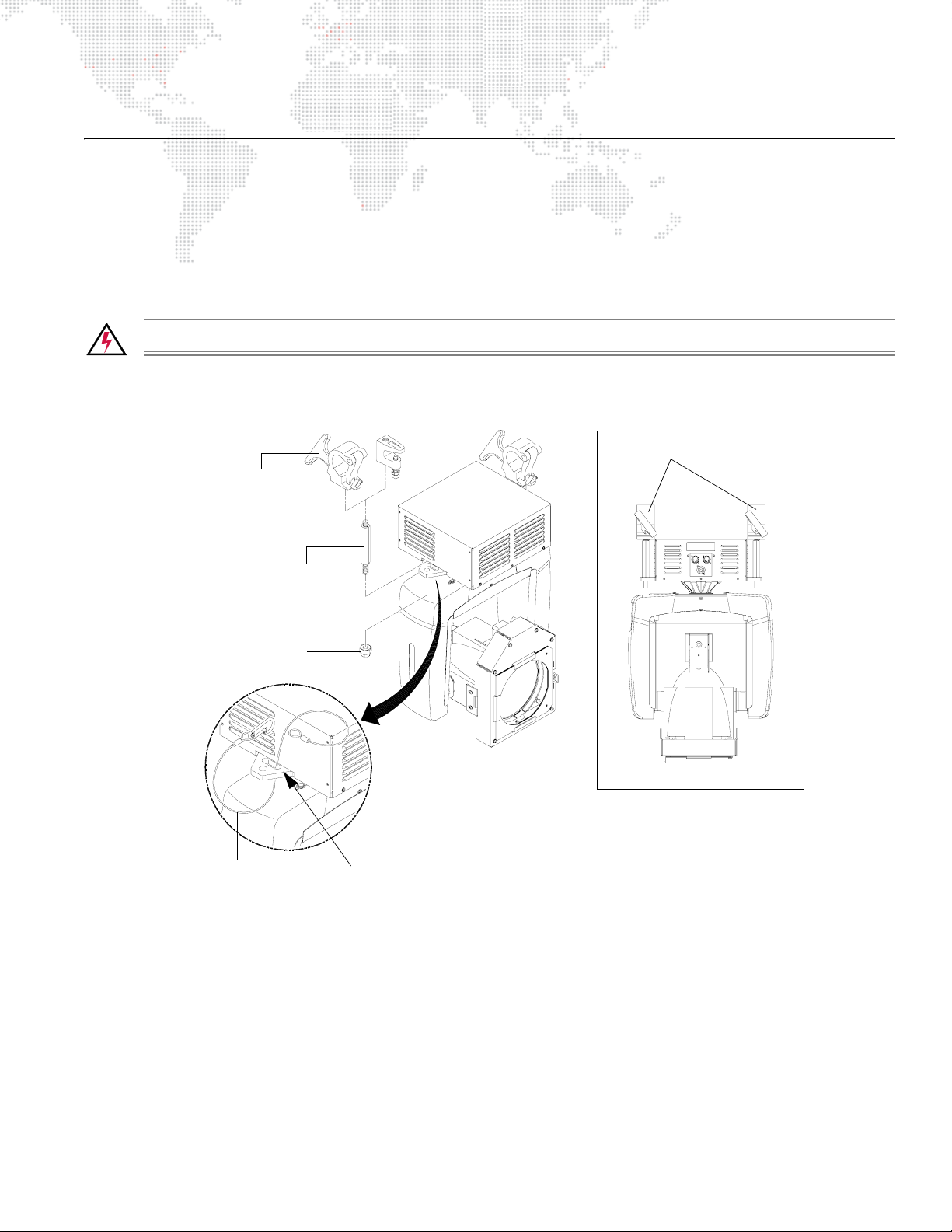
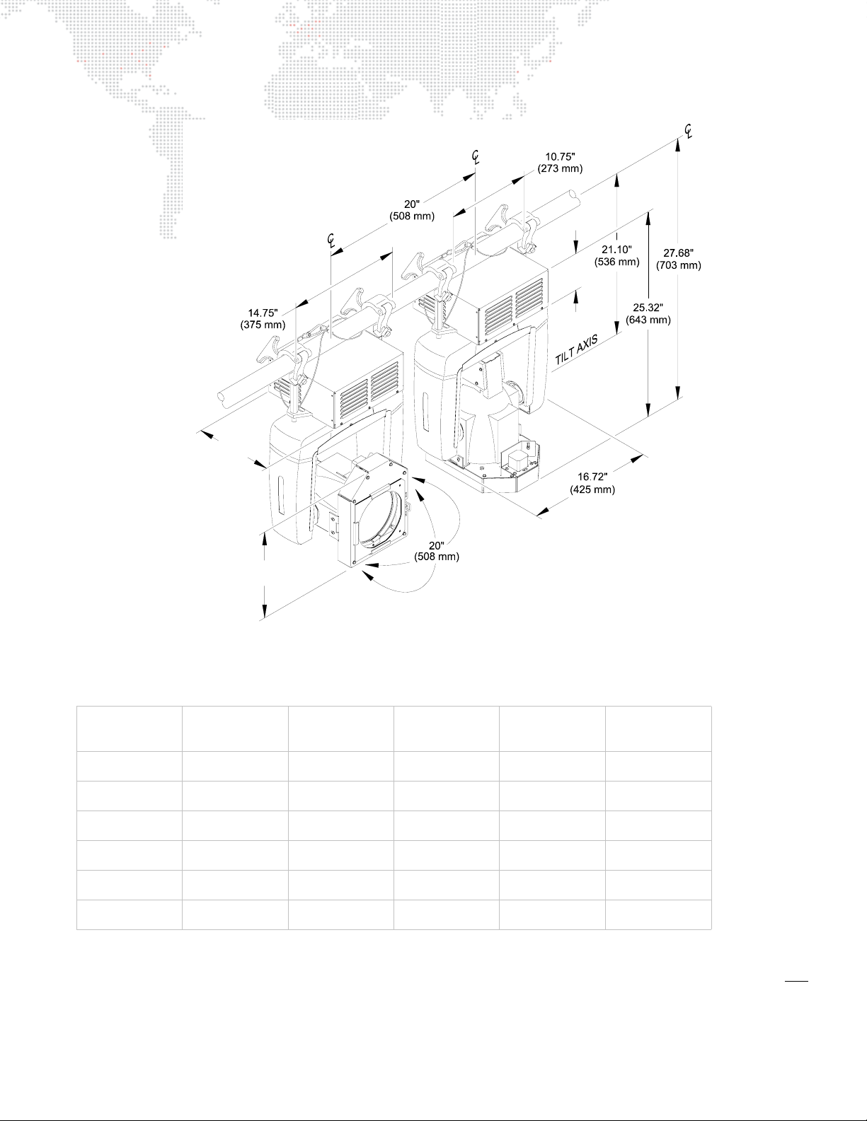
The AutoPar wash luminaire can be hung horizontally or vertically from any structure designed to accommodate the
load created by this moving luminaire. Two provided clamp mounts are used to attach truss hooks or other mounting
hardware as required. A Mega-Claw truss hook is provided, however, other compatible truss hooks are available from
manufacturers such as Grainger.
The safety cable (provided), should be looped through the mounting bracket slot and then attached to the pipe.
WARNING: A safety cable and two truss hooks should be used in all hanging configurations.
Grainger Beam Clamp (2)
Truss Hooks
Mega Claw Hook (2)
Clamp Mount (2)
Flex Top Lock Nut (2)
Safety Cable
FRONT VIEW
Loop safety cable through slot
Figure 2-2: Attaching Truss Hooks and Safety Cable
AUTOPAR® WASH LUMINAIRE USER MANUAL 11
Page 20
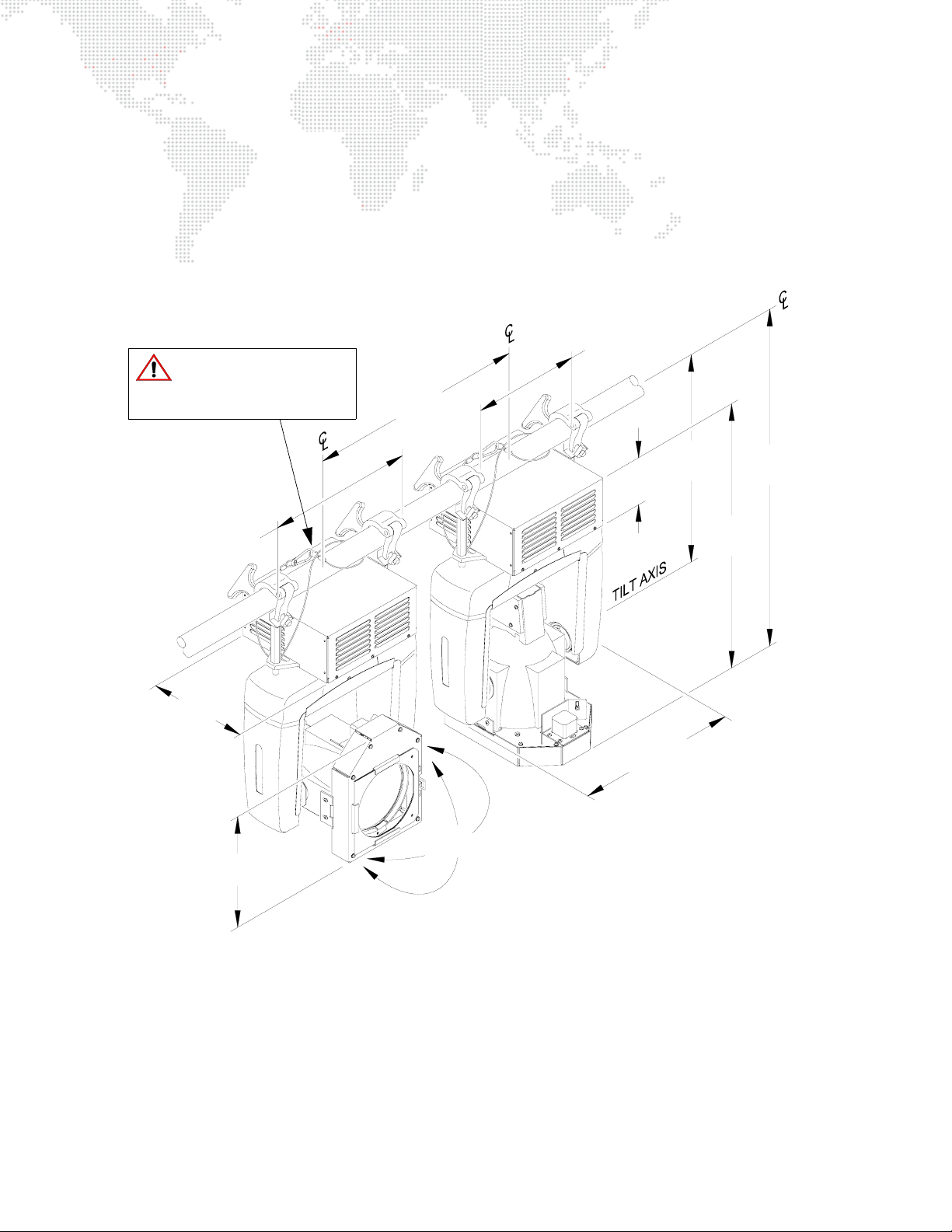
Installing in Truss:
Step 1. Attach hardware and loop safety cable through mounting bracket slot (Figure 2-2).
Step 2. Lift luminaire into mounting position (Figure 2-3).
Step 3. Secure in place with truss hooks. Ensure truss hook hardware (e.g. wing bolt) is properly tightened and that
luminaire is fully supported.
Step 4. Attach safety cable around pipe as shown.
Step 5. Connect power and data cables according to "Connecting Data and Power" on page 13.
10.75"
Safety Cable:
Recommended for all hanging
installations and may be
required by local codes.
20.0"
(508 mm)
(273 mm)
10.12"
(257 mm)
14.75"
(375 mm)
11.38"
(289 mm)
20.0"
(508 mm)
4.80"
(122 mm)
16.72"
(425 mm)
21.10"
(536 mm)
27.68"
(703 mm)
25.32"
(643 mm)
Figure 2-3: Hanging Configuration and Dimensions
12 AUTOPAR® WASH LUMINAIRE USER MANUAL
Page 21
Floor Mounting the Luminaire
The luminaire enclosure is sufficient to stabilize the luminaire in a floor installation, provided
that the mounting surface is flat and sturdy.
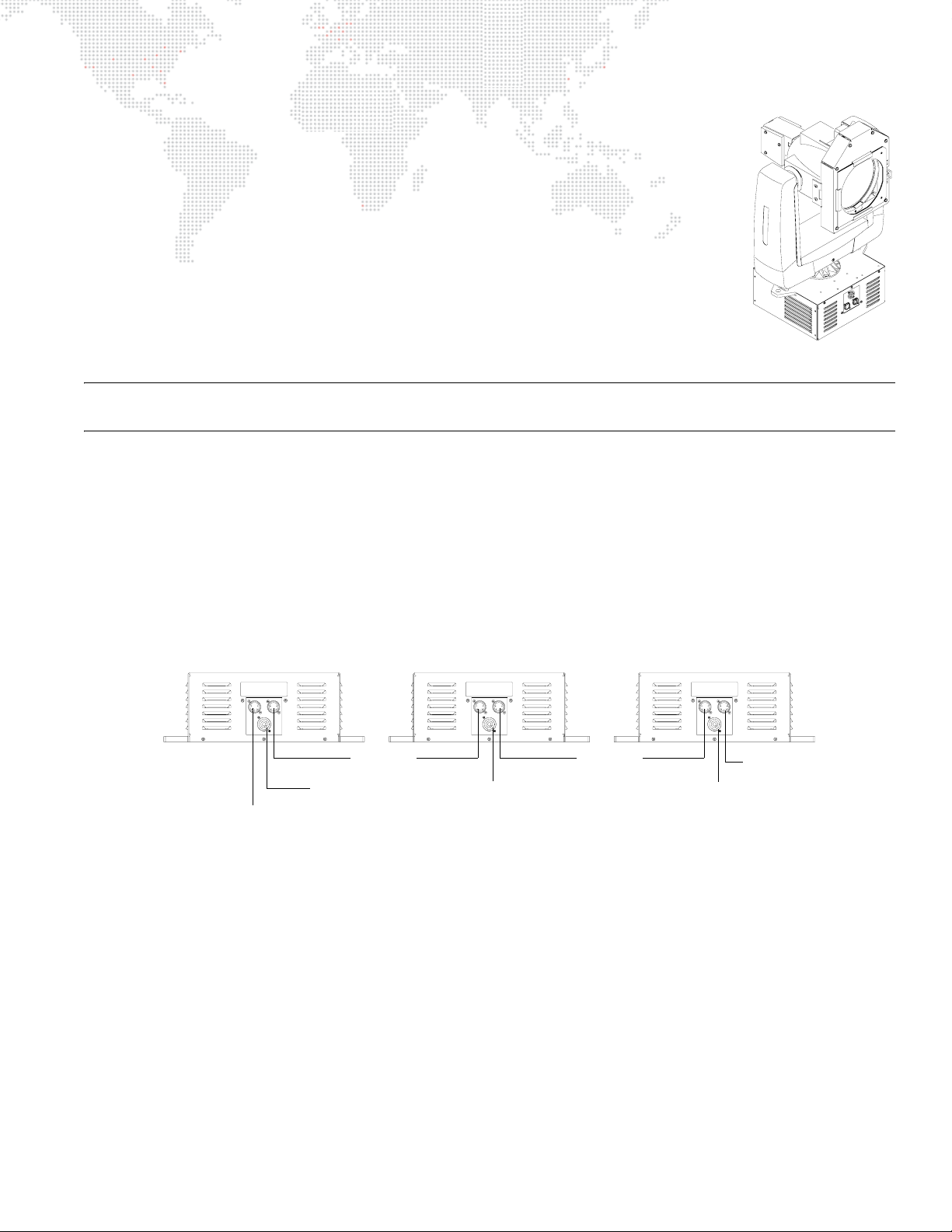
Connecting Data and Power
A maximum of 32 luminaires may be connected in any one DMX data link.
Note: This maximum limit applies to the luminaire "daisy chain" only. Your system or console may require fewer
luminaires on a single data link path. Consult your console documentation for more information.
To connect power and data:
Step 1. Connect data cable from console to first luminaire in chain at DATA IN connector
(Figure 2-4).
Step 2. If required, connect additional data cables from DATA THRU connectors to DATA IN connectors of
remaining luminaires in link.
Step 3. At last luminaire in link, install male termination connector at DATA THRU connector. (Luminaires and other
devices on the same DMX chain may not function properly without termination.)
Step 4. At each luminaire, connect AC cable from power input source.
Step 5. Dress and secure all cables so that they will not interfere with luminaire head or yoke movement.
INPUT RATING:
100-240VAC, 50/60 Hz, 10A MAX
DMX IN DMX THRU
Data In
(from console)
INPUT RATING:
100-240VAC, 50/60 Hz, 10A MAX
DMX IN DMX THRU
Data Thru Data Thru
Power In
Power In
Figure 2-4: Connecting Power and Data Cables
INPUT RATING:
100-240VAC, 50/60 Hz, 10A MAX
DMX IN DMX THRU
Power In
Termination
Connector
AUTOPAR® WASH LUMINAIRE USER MANUAL 13
Page 22
POWER UP PROCEDURE
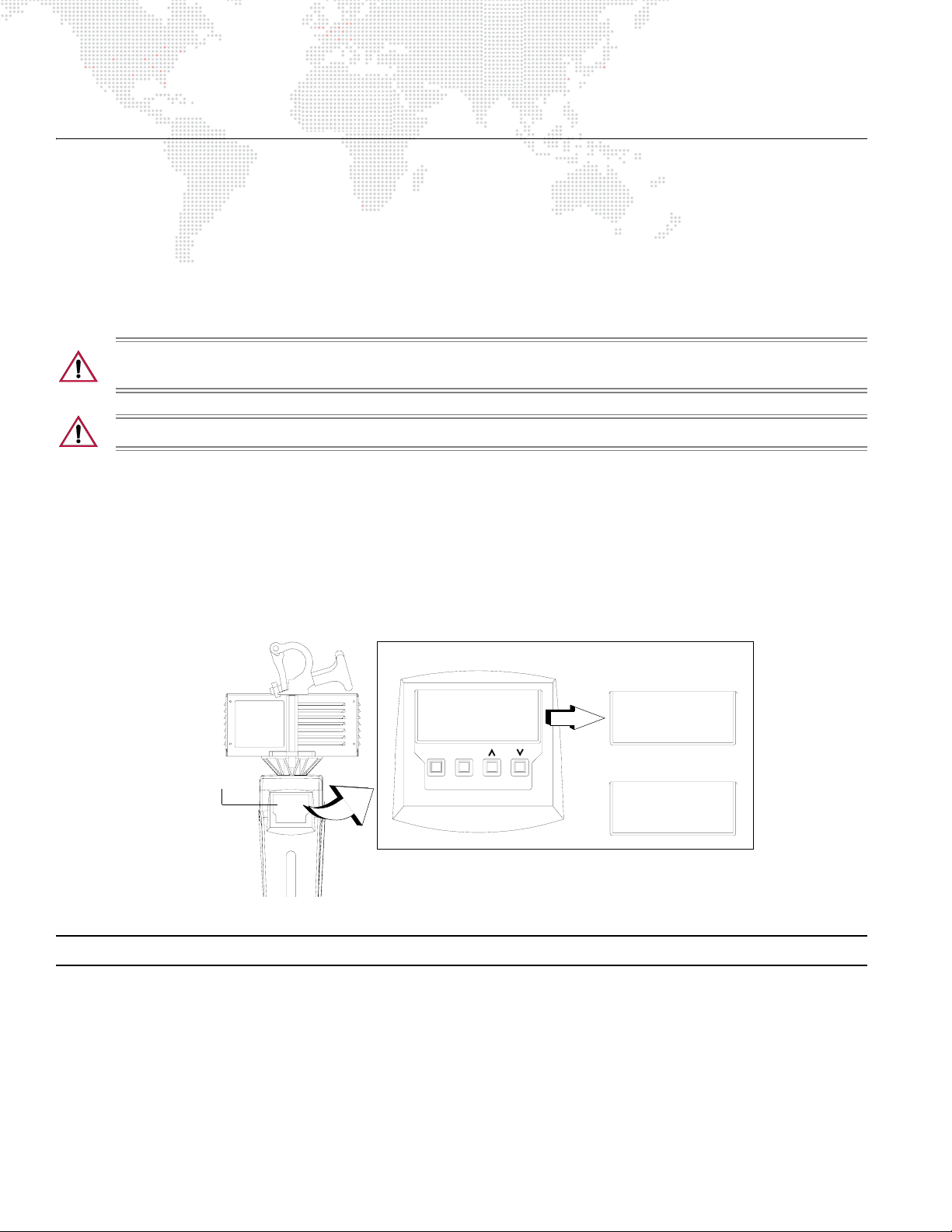
Powering Up the Luminaire
When AC power is applied, the luminaire will begin a calibration sequence which moves its pan, tilt, and lens rotation
mechanisms. After calibration, the luminaire head will either stop at its "home" position (which positions the pan axis
at mid-rotation and the head parallel to the yoke with the lens pointing away from the luminaire upper enclosure) or
move to its current DMX-defined position if DMX512 data is present. The lens rotation mechanism will also move to its
"home" or DMX-defined position.
The lamp is set to off in the default mode. DMX512 control is required to strike the lamp.
CAUTION: Before applying power, be sure the luminaire is hung or positioned so that the head and yoke
can move freely without restriction.
CAUTION: If luminaire is operated without yoke leg covers in place, pan problems will occur.
To power up:
Step 1. At each luminaire, connect AC input cable and apply power. Allow luminaire to complete its calibration
sequence.
Step 2. For normal power up, Display Menu will display "Status OK." After a few seconds, Menu will display a DMX
address or "No Comm" if an address has not been set or no DMX512 signal is detected.
Step 3. To strike lamp, send appropriate DMX512 value from console. Refer to "Control Channel Functions" on
page 21.
Menu Display
Luminaire Status
Status
MENU
ENTER
OK
DMX512 Signal
DMX
1
No Comm
Figure 2-5: Menu Display at Power Up
Note: Refer to "Menu System" on page 18 for more information about the Menu Display.
OR
14 AUTOPAR® WASH LUMINAIRE USER MANUAL
Page 23
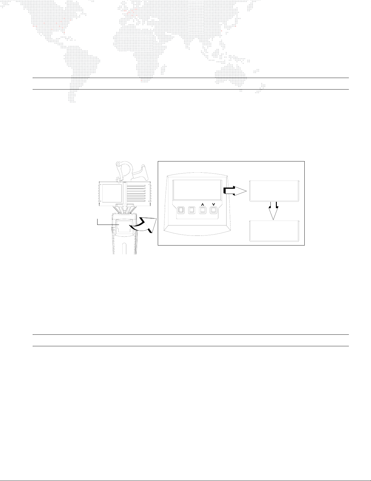
Programming a Starting Address
The address setting for DMX512 systems is programmed at the Menu Display (refer to "Menu System" on page 18 for
more detailed instructions). The luminaire retains its DMX512 address even if power is removed.
Note: Refer to your console operating instructions for specific information regarding its addressing requirements.
Program a DMX512 starting address:
Step 1. Press [Enter] to access top level functions.
Step 2. Press [Up] / [Down] arrows to scroll to Dmx menu. Press [Enter].
Step 3. Press [Up] / [Down] arrows to scroll to Address menu. Press [Enter] to begin edit mode.
Step 4. Press [Up] / [Down] arrows to enter starting address.
Step 5. Press [Enter] to set.
Luminaire Status
Setting DMX512 Address
Menu Display
No Comm
MENU
ENTER
Dmx
Address
30
Figure 2-6: Setting DMX512 Address
Programming Starting Address Without Calibrating
It is possible to bypass the calibration sequence and go directly to the Menu Display programming in order to preprogram an address setting.
Program starting address without calibrating luminaire:
+ While powering up luminaire, press and hold [Menu]. Program address as in Programming a Starting Address
above.
Note: The luminaire will require a reset to restore control.
Configuring Lamp Operation and Other Options
The lamp can be turned off or on using the Menu Display. The luminaire can also be configured to power up with the
lamp on or off. For instructions on setting all menu options, refer to "Menu Functions" on page 19.
AUTOPAR® WASH LUMINAIRE USER MANUAL 15
Page 24

Notes
16 AUTOPAR® WASH LUMINAIRE USER MANUAL
Page 25

3.
OPERATION
This chapter contains instructions for using the Menu Display system and controlling the luminaire by
DMX512.
+
MENU SYSTEM
+ DMX512 OPERATION
+ LUMINAIRE TIMING
Page 26
MENU SYSTEM
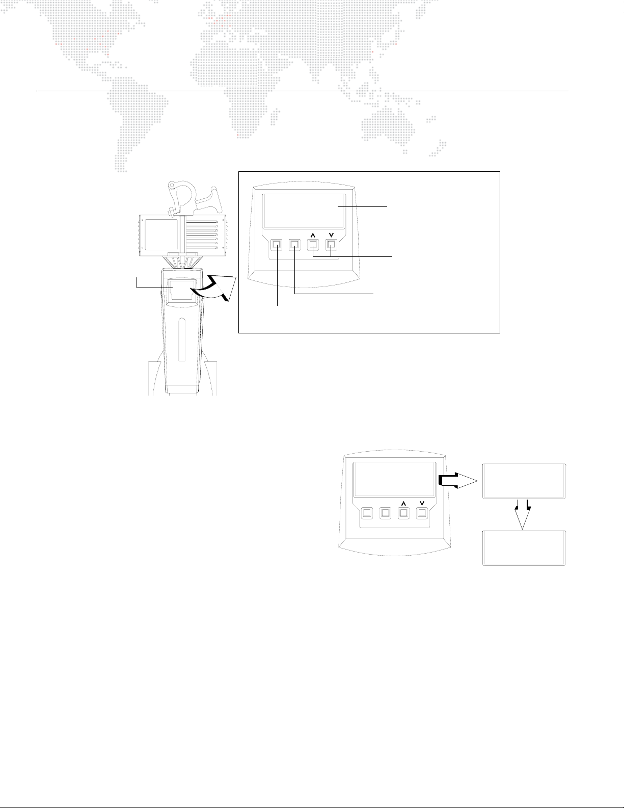
Overview
The menu system is a programmable set of commands used to configure, address, and report status information at
the Menu Display. The system is controlled by four buttons as shown in Figure 3-1.
Address
Menu function or value
30
MENU
ENTER
Changes a value or scrolls
Menu Display
Initiates menu system
or returns to top level
through menu options
Places currently selected
menu into editing mode and
saves any changed settings
Figure 3-1: Menu Display Controls
To enter the menu system, press [Menu]. The first level of
Top Level Menu
functions are referred to as top level functions. Scroll through
the top level functions by pressing [Up] / [Down] arrows. Once
the desired function appears in the display, press [Enter] to
Fixture
move to the sub function. Once again, press the [Up] / [Down]
arrows to scroll through all sub functions. At any function, press
MENU
ENTER
[Enter] to enter editing mode. Use [Up] / [Down] arrows to
program a value or toggle a setting such as On/Off. Press
[Enter] to store the value or setting. Press [Menu] to move up a
level.
Example: Enable tilt reverse option
Figure 3-2: Menu Levels
Step 1. Press [Enter] to access top level functions.
Step 2. Press [Up] / [Down] arrows to scroll to Dmx menu. Press [Enter].
Step 3. Press [Up] / [Down] arrows to scroll to Rev Tilt option. Press [Enter] to begin edit mode.
Step 4. Press [Down] arrow to toggle setting to Yes.
Step 5. Press [Enter] to set.
Sub Level Menus
Status
OK
Serial No
123456
18 AUTOPAR® WASH LUMINAIRE USER MANUAL
Page 27
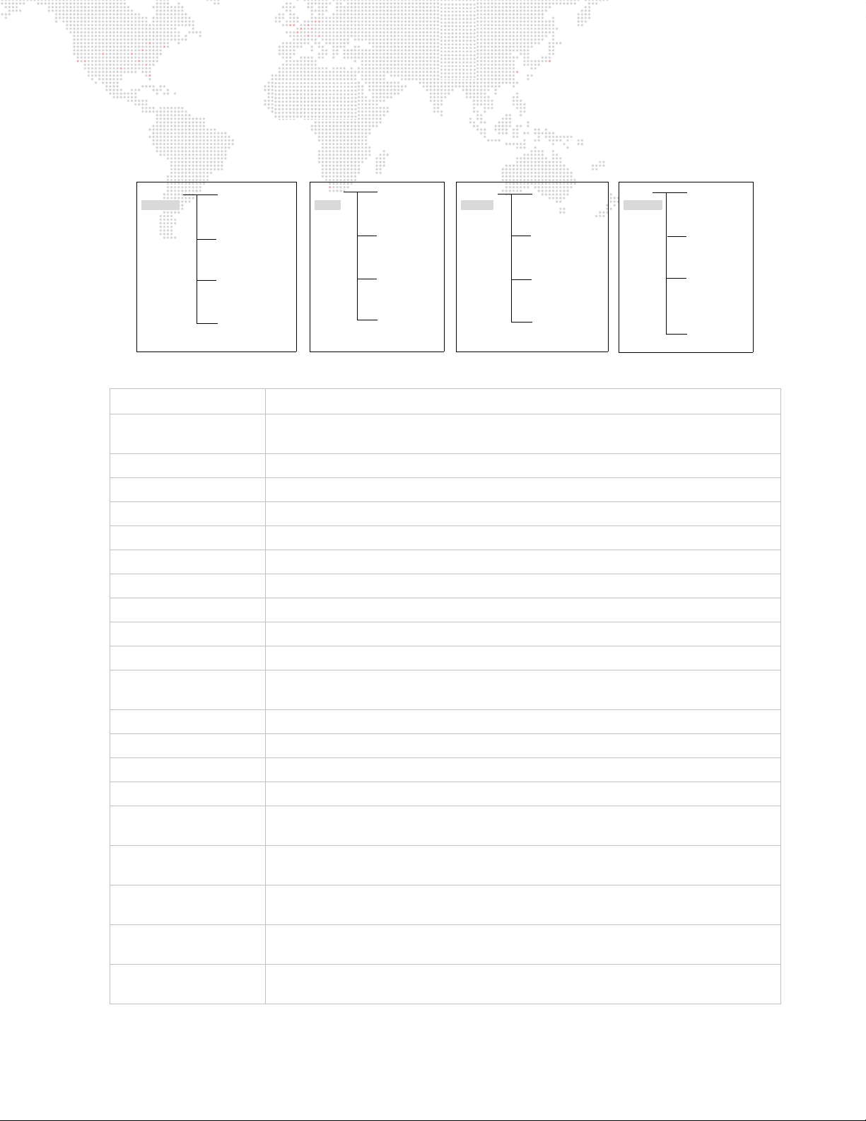
Menu Functions
The following is a graphic representation of the menu system. Fixture, Dmx, Lamp and Tes t are top level functions
which have a series of sub-functions associated with each.
Fixture
Status
OK
Serial No
xxxxxx
Version
xx/xx/xx | x:xx
FixtHours
xxx
Dmx
Function Purpose
Fixture
Status
Serial No
Version
FixtHrs
Dmx
Address
Rev Tilt
Rev Pan
Time Chan
Top level menu which accesses luminaire information such as serial number, software
version, and total operation hours.
Indicates calibration status.
Displays luminaire serial number.
Displays luminaire software version by date and time.
Displays total number of hours luminaire has been powered on.
Top level menu which accesses luminaire DMX address and control options.
Sets DMX512 address.
Sets reverse tilt option: yes or no.
Set reverse pan option: yes or no.
Sets luminaire to Timing Channel Mode: yes or no.
Address
xxx
Rev Tilt
Yes/ No
Rev Pan
Yes/ No
Time Chan
Yes/ No
Lamp
Lamp On
Yes/No
Rst Lamp Hr
Yes/No
LampHours
xxx
Powrup On
Yes/No
Test
Beam Test
Pan Test
Tilt Test
All Tests
Lamp
Lamp On
Reset Lamp Hours
Lamp Hours
Power-up On
Te st
Beam Test
Pan Test
Tilt Test
All Tests
Top level menu which accesses lamp information, turns lamp on or off, and configures
lamp operation at luminaire power-up.
Turns lamp on or off: yes or no.
Resets total lamp operation hours.
Requires a confirmation.
Displays total number of hours lamp has been powered on.
Configures lamp to turn on at luminaire power-up: yes or no (default).
Top level menu which accesses self-test options. Allows tests to be performed without DMX512 input.
NOTE: Tests will not operate if DMX is present.
Rotates lens through a full range of motion at full speed.
Press [Enter] to start. Press any button other than [Enter] to stop.
Moves luminaire head through entire range of pan motion at full speed.
Press [Enter] to start. Press any button other than [Enter] to stop.
Moves luminaire head through entire range of tilt motion at full speed.
Press [Enter] to start. Press any button other than [Enter] to stop.
Runs Beam, Pan and Tilt tests simultaneously at full speed.
Press [Enter] to start. Press any button other than [Enter] to stop.
AUTOPAR® WASH LUMINAIRE USER MANUAL 19
Page 28

DMX512 OPERATION
Channel Mapping
These tables assume a DMX512 start address of 1. When a different starting address is used, this address becomes
channel 1 function and other functions follow in sequence.
DMX Channel Function Default Virtuoso® Control
1 Intensity 0 (dummy channel)
2-3 Pan 32767 Pan
4-5 Tilt 32767 Tilt
6 Lens 0 Beam
7 Control 0 Start/Douse/Reset
DMX Channel Function Default Virtuoso® Control
1 Intensity 0 (dummy channel)
2-3 Pan 32767 Pan
4-5 Tilt 32767 Tilt
6 Lens 0 Beam
7 Focus Time 0 (timing channel)
8 Beam Time 0 (timing channel)
9 Control 0 Start/Douse/Reset
Note: Use Menu Display to enable Timing Channels. Refer to "Menu Functions" on page 19.
20 AUTOPAR® WASH LUMINAIRE USER MANUAL
Page 29

Control Channel Functions
Control channel functions allow special actions such as reset, douse and start. These must be executed with zero
time transition or with console timing disabled. Discrete values must be used; not manual controls such as faders or
encoders (see chart below for values).
Reset - resets all luminaire mechanisms.
Douse - turns lamp off.
Start - strikes lamp.
DMX Value Action
85 Reset
168 Douse
252 Start
To use control channel functions:
Step 1. Select an action to be sent.
Step 2. Set control channel value for desired action (for example, 85 for reset). Hold value for 3 seconds.
Step 3. Set control channel value to zero. (This must occur without any scaling values. Action will be voided if other
values are detected between action value and zero.)
Note: A numerical keypad is required for sending values. An encoder or fader does not allow for a quick value
change, which is required to effect the control functions.
AUTOPAR® WASH LUMINAIRE USER MANUAL 21
Page 30

LUMINAIRE TIMING
Timing Channel Information
Timing channel control allows for smoother transition and movement of the luminaire mechanisms. In this case, timing
channels are provided for focus (pan/tilt) and beam.
Types of timing control:
+ Timing Control Channel: the luminaire uses its timing channel value to calculate a smooth, continuous movement
for a given time and transition.
+ Console Timing: the console calculates the time duration between the DMX512 increments to be sent for a given
time and transition.
Guidelines:
+ Timing channels support time values of up to six minutes.
+ To use a timing channel instead of console timing, it is necessary to set the timing channel to the desired value
and set cue and/or parameter time to zero. A combination of time controls can produce unexpected results.
+ The default value setting in the profile should be 255 (proportional control) to allow smooth movement when using
console timing.
+ The timing channel data should change as a snap. A zero value will give the fastest move, however, without any
smoothing this can appear "steppy" in console timed moves.
Channel Function
Pan (Hi Byte/Lo Byte)
Tilt (Hi Byte/Lo Byte)
Beam
Timing Channel
Focus Time Beam Time
A timing value of zero is full speed. A time value of 100% (or 255 in DMX) enables the associated parameter(s) to
follow cue fade time (console time) rather than the timing channel.
Note: For instructions on storing syntax and writing cues, refer to your particular console manual.
To use these channels, you must:
Step 1. Create the cue, including beam and position settings as required.
Step 2. Decide which fixtures and which parameters will use timing channels.
Step 3. Assign a value to the particular timing channel(s) you wish to use (for timing information, see chart on next
page).
Step 4. Set console timing (or cue fade time) for parameters and timing channels to zero seconds.
Step 5. Store cue.
Note: Avoid changing timing channel values in a fading cue. This can cause unexpected behavior in the luminaire as
the timing channel value is updated over time. Timing channel values and the final destination of the parameters
affected by the timing channel should always be sent in a zero count.
22 AUTOPAR® WASH LUMINAIRE USER MANUAL
Page 31

Timing channels can be set in either % or 0-255 (DMX)
modes, with the following values assigned:
Table 3-1: DMX Mapping
% Value DMX = Seconds
0 Full Speed
10.2
20.4
13 0.6
40.8
25 1
61.2
71.4
38 1.6
91.8
410 2
11 2.2
12 2.4
513 2.6
14 2.8
615 3
16 3.2
17 3.4
718 3.6
19 3.8
820 4
21 4.2
22 4.4
923 4.6
24 4.8
10 25 5
26 5.2
27 5.4
11 28 5.6
29 5.8
30 6
12 31 6.2
32 6.4
13 33 6.6
34 6.8
35 7.0
14 36 7.2
37 7.4
15 38 7.6
Table 3-1: DMX Mapping (Continued)
% Value DMX = Seconds
39 7.8
40 8
16 41 8.2
42 8.4
17 43 8.6
44 8.8
45 9
18 46 9.2
47 9.4
19 48 9.6
49 9.8
50 10
20 51 10.2
52 10.4
53 10.6
21 54 11
55 11
22 56 12
57 12
58 13
23 59 13
60 14
24 61 14
62 14
63 15
25 64 15
65 16
26 66 16
67 16
68 17
27 69 17
70 18
28 71 18
72 18
73 19
29 74 19
75 20
30 76 20
77 20
78 21
31 79 21
80 21
AUTOPAR® WASH LUMINAIRE USER MANUAL 23
Page 32

Table 3-1: DMX Mapping (Continued)
Table 3-1: DMX Mapping (Continued)
% Value DMX = Seconds
81 22
32 82 22
83 23
33 84 23
85 23
86 24
34 87 24
88 25
35 89 25
90 25
91 26
36 92 26
93 27
37 94 27
95 27
96 28
38 97 28
98 29
39 99 29
100 29
101 30
40 102 30
103 30
104 31
41 105 31
106 32
42 107 32
108 32
109 33
43 110 33
111 34
44 112 34
113 34
114 35
45 115 35
116 36
46 117 36
118 36
119 37
47 120 37
121 38
48 122 38
% Value DMX = Seconds
123 38
124 39
49 125 39
126 39
127 40
50 128 40
129 41
51 130 41
131 41
132 42
52 133 42
134 43
53 135 43
136 43
137 44
54 138 44
139 45
55 140 45
141 45
142 46
56 143 46
144 47
57 145 47
146 47
147 48
58 148 48
149 49
59 150 49
151 49
152 50
60 153 50
154 50
155 51
61 156 51
157 52
62 158 52
159 52
160 53
63 161 53
162 54
64 163 54
164 54
24 AUTOPAR® WASH LUMINAIRE USER MANUAL
Page 33

Table 3-1: DMX Mapping (Continued)
Table 3-1: DMX Mapping (Continued)
% Value DMX = Seconds
165 55
65 166 55
167 56
66 168 56
169 56
170 57
67 171 57
172 58
68 173 58
174 58
175 59
69 176 59
177 59
178 60
70 179 60
180 65
71 181 65
182 65
183 70
72 184 70
185 75
73 186 75
187 75
188 80
74 189 80
190 85
75 191 85
192 85
193 90
76 194 90
195 95
77 196 95
197 95
198 100
78 199 100
200 110
79 201 110
202 110
203 120
80 204 120
205 120
81 206 130
% Value DMX = Seconds
207 130
208 140
82 209 140
210 140
211 150
83 212 150
213 160
84 214 160
215 160
216 170
85 217 170
218 180
86 219 180
220 180
221 190
87 222 190
223 200
88 224 200
225 200
226 210
89 227 210
228 210
229 220
90 230 220
231 230
91 232 230
233 230
234 240
92 235 240
236 250
93 237 250
238 250
239 260
94 240 260
241 270
95 242 270
243 270
244 280
96 245 280
246 290
97 247 290
248 290
AUTOPAR® WASH LUMINAIRE USER MANUAL 25
Page 34

Table 3-1: DMX Mapping (Continued)
% Value DMX = Seconds
249 300
98 250 300
251 310
99 252 310
253 310
254 310
100 255 Follows Cue Data
26 AUTOPAR® WASH LUMINAIRE USER MANUAL
Page 35

4.
TROUBLESHOOTING AND MAINTENANCE
This chapter provides a basic troubleshooting guide, along with procedures for extended care of the
luminaire.
+
TROUBL ESH OOT ING
+ ROUTINE MAINTENANCE
Page 36
TROUBLESHOOTING
Error Messages
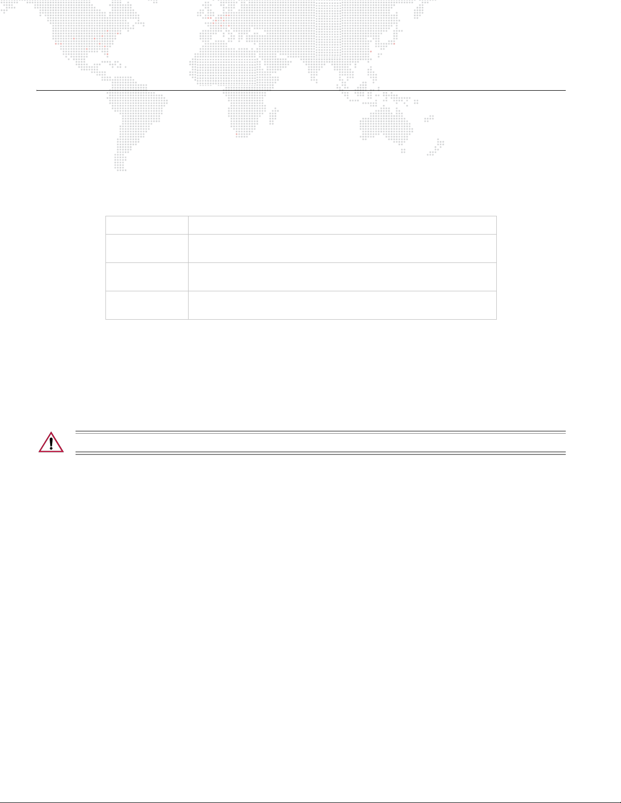
After calibration, the Menu Display will cycle through any applicable error message(s), one a time until the end of the
list is reached. To review the error messages again, it will be necessary to access them using the Status function.
The following table provides all possible error messages. These errors can be reported for each mechanism (Pan, Tilt,
or Beam), except Enc Fail which does not apply to the Beam mechanism.
Display Cause
No Sensor
Sensor On
Enc Fail
The active sensor state was not detected during calibration. Mechanism
not moving (off sensor), sensor broken or disconnected.
The sensor was stuck active during calibration. Mechanism not moving
(on sensor), sensor broken or disconnected.
The encoder was not changing during pan or tilt calibration. Mechanism
not moving, encoder broken or disconnected.
To access error messages:
Step 1. Press [Enter] to access top level functions.
Step 2. Press [Up] / [Down] arrows to scroll to Fixture menu. Press [Enter].
Step 3. Press [Up] / [Down] arrows to access Status. (Display will scroll through any error messages or display OK
if no errors.)
CAUTION: If luminaire is operated without yoke leg covers in place, pan problems will occur.
28 AUTOPAR® WASH LUMINAIRE USER MANUAL
Page 37

Troubleshooting Guide
The following table provides a list of common failures and possible solutions.
Symptom Message Solution(s) Refer to...
Ensure power cable is properly connected to Neutrik
input connector.
No power to luminaire. n/a
No DMX512 control. No Comm
DMX512 control not working
correctly throughout daisy chain.
Erratic control of luminaire(s). n/a
n/a
Ensure power is switched on at source (mains,
disconnect box, etc.)
Ensure data cable is connected to DMX In connector.
Ensure DMX512 address setting is correct.
Ensure data cables are correctly configured.
Ensure termination connector is installed at last
luminaire in data link.
Ensure termination connector is installed at last
luminaire in data link.
Ensure termination connector is properly configured.
page 13
page 13
page 15
page 13
page 13
page 13
page 10
Lamp does not strike at power-up. n/a Configure lamp to start at power-up.
Timing Channels not working. n/a Ensure Timing Channels are enabled.
Pan mechanism not operating
correctly.
n/a
Ensure yoke leg covers are installed. (Light beams from
adjacent fixtures can affect the optical pan encoder,
causing it to lose track.)
page 19
page 20
n/a
AUTOPAR® WASH LUMINAIRE USER MANUAL 29
Page 38
ROUTINE MAINTENANCE
Replacing Lamp
Parts:
71.2566.0700.0 LAMP, MSR 700W
Tools:
#2 Phillips Screwdriver
WARNING: Remove power from luminaire before performing any maintenance procedures.
CAUTION: Wear cotton gloves or other covering while installing lamp. Touching lamp glass with bare
fingers will leave oil and may cause the lamp to explode or reduce lamp life. If touched, use alcohol and
cotton cloth to thoroughly clean glass portion of lamp.
To replace lamp:
Step 1. Remove power from luminaire and allow lamp to cool.
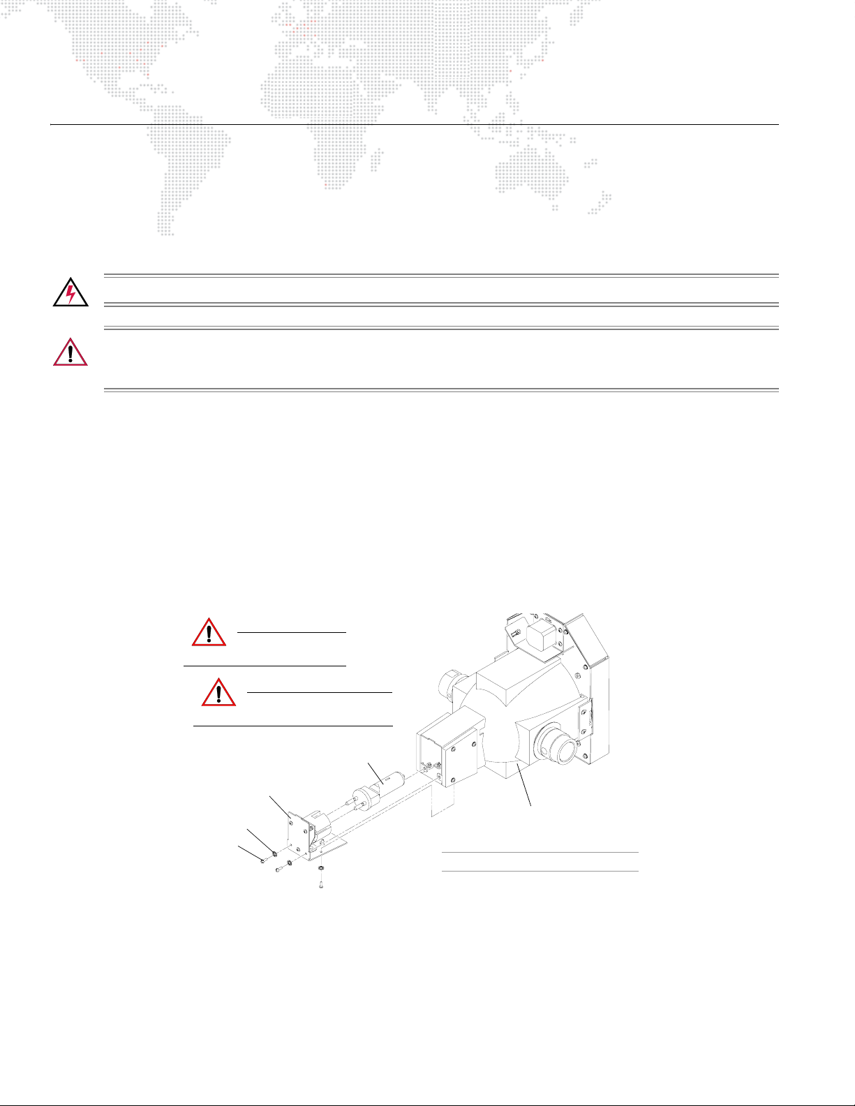
Step 2. At backcap, remove four tamper-proof screws and lock washers (Figure 4-1).
Step 3. Pull backcap straight back and out of head assembly.
Step 4. Gripping lamp at base, remove from socket.
Step 5. Install new lamp.
Step 6. Reset lamp hours as required. Refer to "Menu Functions" on page 19.
Step 7. Align lamp according to procedure on next page.
CAUTION:
CAUTION:
Backcap
#6 Int. Tooth
Lock Washer (4)
Tamper-Proof
Screw (4)
Allow lamp to cool
before servicing.
Do not touch lamp or
reflector with bare fingers.
Lamp
Figure 4-1: Replacing Lamp
Head Assembly
Luminaire Yoke Not Shown For Clarity
30 AUTOPAR® WASH LUMINAIRE USER MANUAL
Page 39
Aligning Lamp
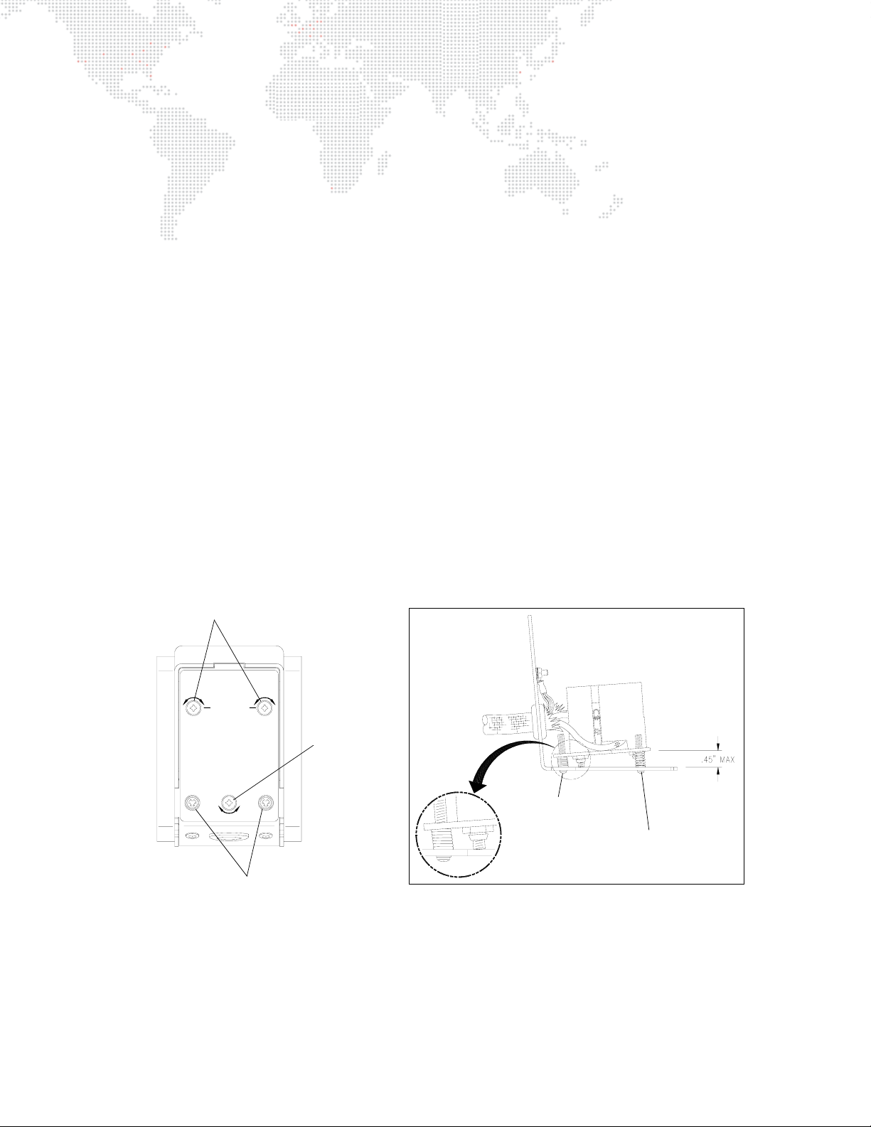
After a new lamp is installed, it will be necessary to align the lamp to optimize the beam. Screws located at the
luminaire’s backcap allow for adjustment.
Tools:
#2 Phillips screwdriver
Light meter
To align lamp:
Step 1. Remove power from luminaire.
Step 2. Remove front lens (refer to "Replacing Front Lens" on page 32).
Step 3. At backcap, using
centered within the reflector hole. This can be done by visually looking at the lamp from the front (while the
lens is removed).
Step 4. Once lamp is centered, install a clear lens. (Lenticular lenses are not recommended for alignment
purposes.)
Step 5. Power-up luminaire, strike lamp and allow it to achieve full brightness (about 1 minute).
Step 6. Position beam on a white wall at a distance of 10 to 20 feet.
Step 7. Using two adjustment screws, adjust as needed so that "hot spot" is centered within beam.
Step 8. Using meter and two adjustment screws, adjust so that brightness is maximized as follows:
a. Turn adjustment screws equally 1/2 turn clockwise
brightness increases or decreases. Do one of the following:
1)
If brightness increases
increases.
2)
If brightness decreases
only
top two adjustment screws (as shown in Figure 4-2), align lamp so that it is
or
counterclockwise. Using light meter, note whether
, try turning screws in 1/2 turn in same direction until brightness no longer
, turn screws back 1/2 turn (to original position).
Lamp Adjustment Screws
CAUTION
LAMP ADJUST
DANGER: INTENSE HEAT.
DISCONNECT FIXTURE AND ALLOW
HOUSING TO COOL FOR
15 MINUTES BEFORE RELAMPING.
RISK OF FIRE. USE ONLY
MSR 700 WATT METAL HALIDE
LAMP, G22 BASE.
RELAMP
x2
BACKCAP
RELAMP
LAMP ADJUST
x2
Backcap Removal Screws
INTERIOR DETAIL
Not Used
(Factory Set See Detail)
Spring should be fully
compressed as shown
Lamp Adjustment
Screws
Figure 4-2: Lamp Adjustment Screws
AUTOPAR® WASH LUMINAIRE USER MANUAL 31
Page 40
Replacing Front Lens
The luminaire includes four different front lens which can be swapped as needed.
Parts:
LENS, VERY NARROW
LENS, NARROW
LENS, 8-ROW LENTICULAR
LENS, 12-ROW LENTICULAR
Tools:
none
WARNING: Remove power from luminaire before performing any maintenance procedures.
To replace Front Lens:
Step 1. Remove power from luminaire.
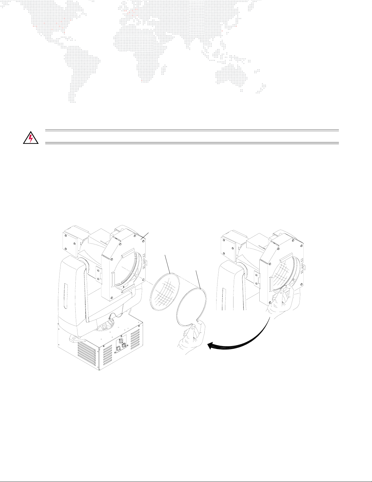
Step 2. At securing ring, squeeze flanges and remove (Figure 4-3).
Step 3. Remove Front Lens.
Step 4. Align raised areas on back of new Front Lens with notches in Rotation Assembly. (Lens can be installed in
one of two 180° orientations.)
Step 5. Re-install securing ring, ensuring it is fully seated in its groove.
Lens Rotation Assembly
Front Lens
Securing Ring
Figure 4-3: Replacing Front Lens
Squeeze flanges
to loosen
32 AUTOPAR® WASH LUMINAIRE USER MANUAL
Page 41
Installing a Color Gel
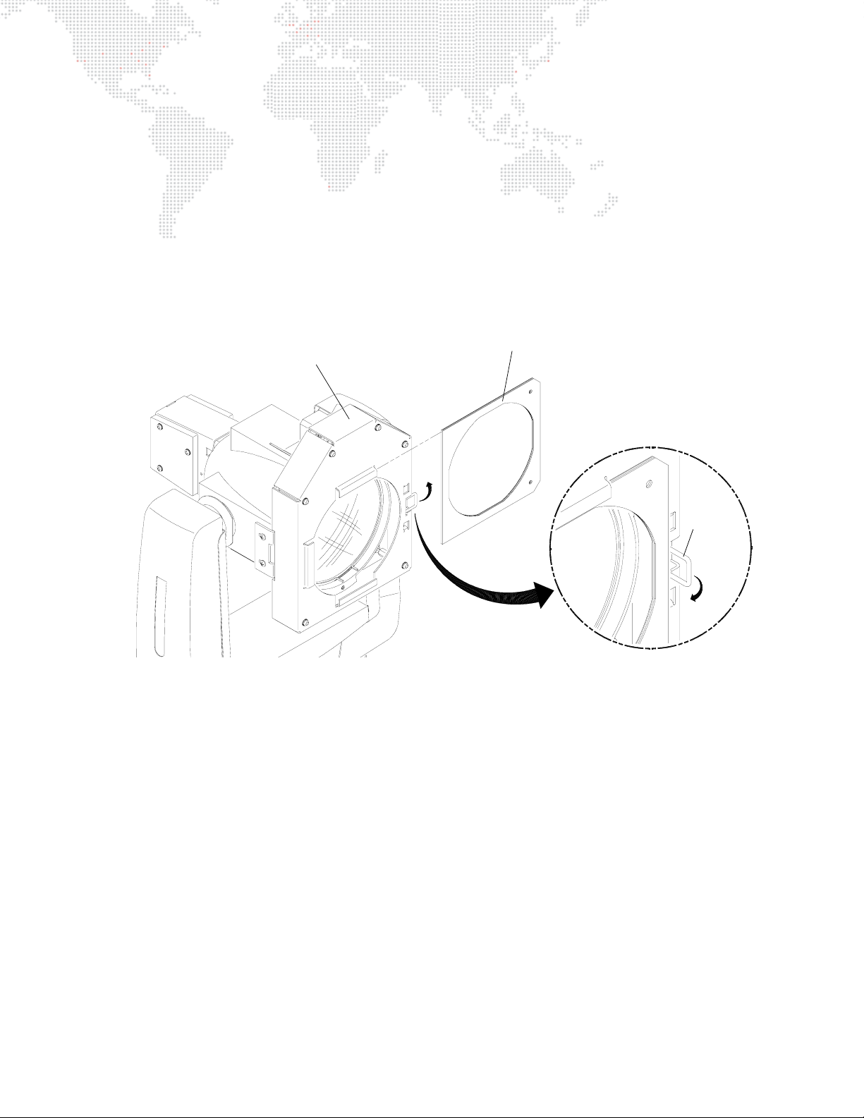
Color gels can be installed in the gel frame located at the front of the head assembly.
Tools:
none
To install/replace a color gel:
Step 1. At front of luminaire, press latch to release gel frame as shown (Figure 4-4).
Step 2. Remove gel frame from luminaire.
Step 3. Install color gel in frame.
Step 4. Re-install gel frame in luminaire and close latch.
Head Assembly
Figure 4-4: Installing/Replacing a Color Gel
Gel Frame
Latch
AUTOPAR® WASH LUMINAIRE USER MANUAL 33
Page 42
Cleaning the Luminaire
Tools:
Window cleaner (commercial grade)
Clean, lint-free cloth
Vacuum cleaner with brush nozzle
To clean the outside of the luminaire:
WARNING: Remove power from luminaire before performing any maintenance procedures.
Step 1. Remove power from luminaire.
Step 2. Using vacuum cleaner with brush nozzle, gently clean dust from external components.
Step 3. Apply window cleaner sparingly to clean, lint-free cloth.
Step 4. Wipe outside surface of luminaire with cloth.
34 AUTOPAR® WASH LUMINAIRE USER MANUAL
Page 43

A.
TECHNICAL SPECIFICATIONS
Page 44

AutoPar Wash Luminaire
Description
SOURCE: Philips MSR700 1CT 700W arc lamp
Color Temp: 5600°K
CRI: 85
BALLAST: Integrated electronic ballast with universal input and power factor correction.
REFLECTOR: Modified parabolic, multifaceted reflector finished with a metal cold mirror dichroic coating.
UV FILTER: Internal coated filter. Rejects greater than 99% of ultra-violet radiation.
LENSES: Four heat resistant, molded borosilicate glass lenses included:
Very Narrow Spot, Narrow Spot, 8-Row Lenticular, and 12-Row Lenticular.
OUTPUT: 30,000 lumens
COLOR: Gel frame holder allows tool-free replacement of standard color gels.
TEMP RANGE: -20° to 120° F (-29° to 49° C)
COOLING: Ballast: forced air
Head and Yoke: free convection
CONTROL: Control by DMX512. Uses nine DMX512 channels.
POSITIONING: Can be mounted and operated in any orientation.
SPACING: Hangs on 20 inch (508 mm) centers.
WEIGHT: 38 lbs (17 kg)
POWER REQ. 120V/8A, 208V/4A
Programmable Functions
LAMP CONTROL: Remote start and douse from console.
ROTATING LENS: Programmable rotating front lens assembly with 200° range and 5 second full travel.
PAN AND TILT: Smooth, timed continuous motion by way of three-phase stepper motors.
RANGE: Pan - 360° and Tilt - 240° @ 60° per second.
ACCURACY: 0.3° resolution.
36 AUTOPAR® WASH LUMINAIRE USER MANUAL
Page 45
10.12"
(257 mm)
11.38"
(289 mm)
Photometric Data
AutoPar Luminaire with MSR700 Lamp
4.80"
(122 mm)
LENS
VNSP 1,625,000 5° 0.087 14° 0.246
NSP 1,155,000 7.5° 0.131 15° 0.263
8-Row Horiz 360,000 18° 0.317 31° 0.555
8-Row Vert 360,000 12° 0.210 23° 0.407
12-Row Horiz 140,000 31° 0.555 50° 0.933
12-Row Vert 140,000 21° 0.371 33° 0.592
CANDELA
(cd) **
BEAM ANGLE
(degrees)
BEAM
(Tn) *
FIELD ANGLE
(degrees)
FIELD
(Tn) *
* Multiply throw distance by Tn to determine coverage.
**To calculate center beam illuminance (I) at a specific distance (D):
-- if (D) is in feet, (I) is in foot candles
-- if (D) is in meters, (I) is in lux
AUTOPAR® WASH LUMINAIRE USER MANUAL 37
I =
cd
D
2
Page 46

Notes
38 AUTOPAR® WASH LUMINAIRE USER MANUAL
Page 47

AutoPar® Wash Luminaire User Manual
Version as of: November 8, 2010
PRG part number: 02.9802.0001.21
Page 48

Production Resource Group
Dallas Office
8617 Ambassador Row, Suite 120
Dallas, Texas 75247
www.prg.com
 Loading...