

Prexiso G5, G4, G4 Series, G5 Series, G4 GSM User Manual
...
Prexiso G4/G5
User Manual
Version 1.0
G4/G5 | 2Introduction
Introduction
Purchase Congratulations on the purchase of a Prexiso G4/G5 GNSS instrument.
This manual contains important safety directions as well as instructions for setting
up the product and operating it. Refer to "5 Safety Directions" for further information.
Read carefully through the User Manual before you switch on the product.
Product identification
The type and serial number of your product are indicated on the type plate.
Enter the type and serial number in your manual and always refer to this information
when you need to contact your agency or Prexiso authorised service workshop.
Symbols The symbols used in this manual have the following meanings:
Type: _____________________________________
Serial No.: _____________________________________
Type Description
DANGER Indicates an imminently hazardous situation which, if not
avoided, will result in death or serious injury.
Introduction G4/G5 | 3
Trademarks • Windows is a registered trademark of Microsoft Corporation in the United
States and other countries
• Bluetooth is a registered trademark of Bluetooth SIG, Inc.
• microSD is a trademark of the SD Card Association
All other trademarks are the property of their respective owners.
Validity of this
manual
This manual applies to the G4/G5 instruments. Differences between the models are
marked and described.
WARNING Indicates a potentially hazardous situation or an unintended
use which, if not avoided, could result in death or serious
injury.
CAUTION Indicates a potentially hazardous situation or an unintended
use which, if not avoided, may result in minor or moderate
injury and/or appreciable material, financial and environmental damage.
)
Important paragraphs which must be adhered to in practice
as they enable the product to be used in a technically correct
and efficient manner.
Type Description

G4/G5 | 4Introduction
Available documentation
Refer to the following resources for all G4/G5 documentation/software:
• the Prexiso G4/G5 CD
• www.prexiso.com
Name Description/Format
G4/G5 Quick
Guide
Provides an overview of the product together with
technical data and safety directions. Intended as a
quick reference guide.
99
G4/G5 User
Manual
All instructions required in order to operate the product
to a basic level are contained in the User Manual.
Provides an overview of the product together with
technical data and safety directions.
- 9
PREXISO
User Manual
Version
Table of Contents G4/G5 | 5
Table of Contents
In this manual Chapter Page
1 Description of the System
8
1.1 System Components 8
1.2 Container Contents 10
1.3 Instrument Components 11
1.4 System Concept 12
1.4.1 Software Concept 12
1.4.2 Power Concept 13
1.4.3 Data Storage Concept 14
2 User Interface
15
2.1 Keyboard 15
2.2 Operating Principles 19
3 Operation
20
3.1 Equipment Setup 20
3.1.1 Setting up as a Real-Time Base 20
3.1.2 Setting up as a Post-Processing Base 23
3.1.3 Setting Up as a Real-Time Rover 25
3.1.4 Fixing the handheld to a holder and pole 27
G4/G5 | 6Table of Contents
3.1.5 Connecting to a Personal Computer 29
3.1.6 Configuring the Instrument 31
3.1.7 The Mechanical Reference Plane, MRP 32
3.2 Batteries 33
3.2.1 Operating Principles 33
3.2.2 Battery for instrument 35
3.3 Working with the Data Storage Device 37
3.4 Working with the RTK Device 39
3.5 LED Indicators 41
3.6 Guidelines for Correct Results with GNSS Surveys 44
4 Care and Transport
45
4.1 Transport 45
4.2 Storage 46
4.3 Cleaning and Drying 47
5 Safety Directions
48
5.1 General Introduction 48
5.2 Intended Use 49
5.3 Limits of Use 51
5.4 Responsibilities 52
5.5 Hazards of Use 54

Table of Contents G4/G5 | 7
5.6 Electromagnetic Compatibility EMC 64
5.7 FCC Statement, Applicable in U.S. 67
6 Technical Data
70
6.1 G4/G5 Technical Data 70
6.1.1 Tracking Characteristics 70
6.1.2 Accuracy 71
6.1.3 Technical Data 73
6.2 Conformity to National Regulations 77
6.2.1 G4/G5 77
7 International Limited Warranty, Software Licence Agreement
81
Appendix A Pin Assignments and Sockets
83
A.1 Instrument 83
Index
85
G4/G5 | 8Description of the System
1 Description of the System
1.1 System Components
Main components
Instruments Depending on the satellite systems and signals configured, a maximum number of
72 channels (G4) or 120 channels (G5) is allocated.
Component Description
Instrument To receive the satellite signals and calculate a position
from the computed ranges to all visible GNSS (Global
Navigation Satellite System) satellites.
Getac PPS236 handheld
Handheld to operate the instrument.
Survey field software The software used on the handheld for performing various
surveying applications.
Instrument Description
G4 Up to 14 L1, 14 L2 channels (GPS), 12 L1, 12 L2 channels
(GLONASS), code and phase, real-time capable
Description of the System G4/G5 | 9
)
For GLONASS tracking a licence key has to be uploaded to the instrument
with Prexiso Assistant.
Available models
*1 removable
G5 Up to 16 L1, 16 L2, (GPS), up to 14 L1, 14 L2 channels
(GLONASS), Galileo, code and phase, real-time capable
Instrument Description
Model
Internal radio
modem
Internal GSM
modem
Internal battery
*1
Bluetooth
G4 GSM-UHF 99 99
G4 GSM - 999
G5 GSM-UHF 99 99
G5 GSM - 999

G4/G5 | 10Description of the System
1.2 Container Contents
Container for instrument and accessories
a) PBA202 batteries
b) G4/G5 instrument
c) Antennas of device
d) PPC210 base pole
e) Connection screw
f) Carrier
g) Tribrach
h) Measuring tape
i) USB cable
j) Adapter for charger
k) Pole holder
l) Getac PPS236 handheld
m) PCH202 battery charger
n) Manual and CD
gfh
jiklmn
ab cd e
Description of the System G4/G5 | 11
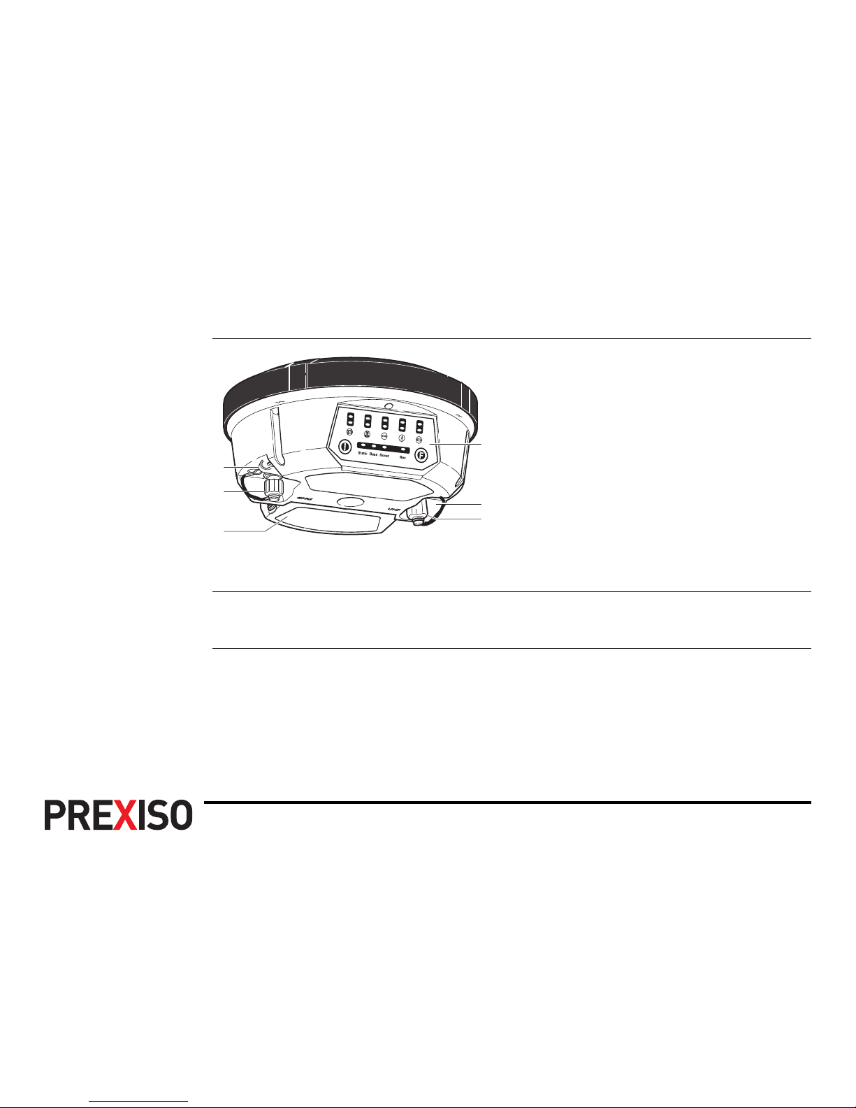
1.3 Instrument Components
Instrument components
)
A Bluetooth port is included inside the instrument to enable connectivity to a
controller.
a) LEMO port 1
b) TNC connector for GSM antenna
c) Battery compartment with SIM card
and microSD card holder
d) LEDs, ON/OFF button and Function
button
e) LEMO port 2
f) TNC connector for UHF antenna
a
e
f
d
b
c
G4/G5 | 12Description of the System
1.4 System Concept
1.4.1 Software Concept
Instrument software
Software upload The firmware can be uploaded using Prexiso Assistant.
)
Uploading instrument firmware can take some time. Ensure that the battery
is at least 75% full before beginning the upload, and do not remove the
battery during the upload process.
The instrument has to be restarted after the firmware upload.
Software type Description
Instrument firmware
(xx.bin)
This important software covers all functions of the instrument.

Description of the System G4/G5 | 13
1.4.2 Power Concept
General Use the Prexiso batteries, chargers and accessories or accessories recommended by
Prexiso to ensure the correct functionality of the instrument.
Power options Power for the instrument can be supplied either internally or externally.
Internal power supply: One PBA202 battery fitting into the instrument.
External power supply: 9 V to 18 V DC power supply via cable.

G4/G5 | 14Description of the System
1.4.3 Data Storage Concept
Description Data (GNSS raw data and RINEX data) can be recorded on a microSD card or
internal memory.
Data storage device
)
Unplugging connecting cables or removing the microSD card during the measurement can cause loss of data. Only remove the microSD card or unplug connecting
cables when the instrument is switched off.
microSD card: The instrument has a microSD card holder fitted as
standard. A microSD card can be inserted and removed.
Capacity: Up to 4 GB.
Internal memory: The instrument has an internal memory fitted as
standard. Available capacity: 256 MB.

User Interface G4/G5 | 15
2 User Interface
2.1 Keyboard
Keyboard
a) ON/OFF button
b) Function button
ab
G4/G5 | 16User Interface
ON/OFF button
Button Function
ON/OFF • Turn on instrument:
Hold button for 1 s.
)
While the instrument is booting all LEDs are
lighted (except the blue Bluetooth LED and the red
Power LED). Once the instrument has started, the
normal LED behaviour starts.
• Turn off instrument:
Hold button for 3 s until instrument beeps 3 times and
only the red power LED is lighted.
User Interface G4/G5 | 17
• Instrument self-check:
While the instrument is turned on hold button for 10 s until
the instrument beeps once. The instrument performs a
self-check.
)
An instrument self-check can be performed to
check if the communication of the internal GNSS
board, radio module and GSM module is working
correctly.
– If the green Satellite, UHF and GPRS LED are on, the
communication of the internal GNSS board, radio
module and GSM module is working correctly. The
instrument reboots 5 s after finishing the self-check.
– If the red Satellite, UHF or GPRS LED is on, the
communication of the internal GNSS board, radio
module or GSM module might not work correctly. The
instrument starts beeping. Press any key to reboot the
instrument and contact your local Prexiso dealer.
Button Function
G4/G5 | 18User Interface
Function button
)
The function described assumes that the instrument is turned on.
Button combination
)
The function described assumes that the instrument is turned off.
Button Function
Function • Switch datalink
Press and hold button for 1 s to switch between the datalink options UHF, GPRS and Bluetooth. The corresponding
green LED flashes. To select the datalink, press and hold
the power button for 1 s.
Button Function
ON/OFF • Switch working mode
Function Press and hold buttons for 6 s until all LEDs flash (except
for the blue Bluetooth LED). Press and hold Function
button for 1 s to switch between the working mode
options Static, Base and Rover. The corresponding LED
flashes. To select the working mode, press and hold the
ON/OFF button for 1 s.
User Interface G4/G5 | 19
2.2 Operating Principles
Operating the
instrument
The instrument is operated either by the pressing its buttons (ON/OFF button, Function button) or by a handheld.
Operation by buttons
The instrument is operated by pressing its buttons. Refer to "2.1 Keyboard" for a
description of the buttons and their function.
Operation by handheld
The instrument is operated by a handheld. Refer to the Field Software User Manual
for more information.
Turn on instrument To turn on the instrument press and hold the ON/OFF button for 1 s.
Turn off instrument To turn off the instrument press and hold the ON/OFF button for 3 s until the instru-
ment beeps 3 times and only the red power LED is lighted.

G4/G5 | 20Operation
3 Operation
3.1 Equipment Setup
3.1.1 Setting up as a Real-Time Base
Use The following equipment setup is used for real-time base stations with the need of
optimal radio coverage. Raw observation data can also be collected for postprocessing.
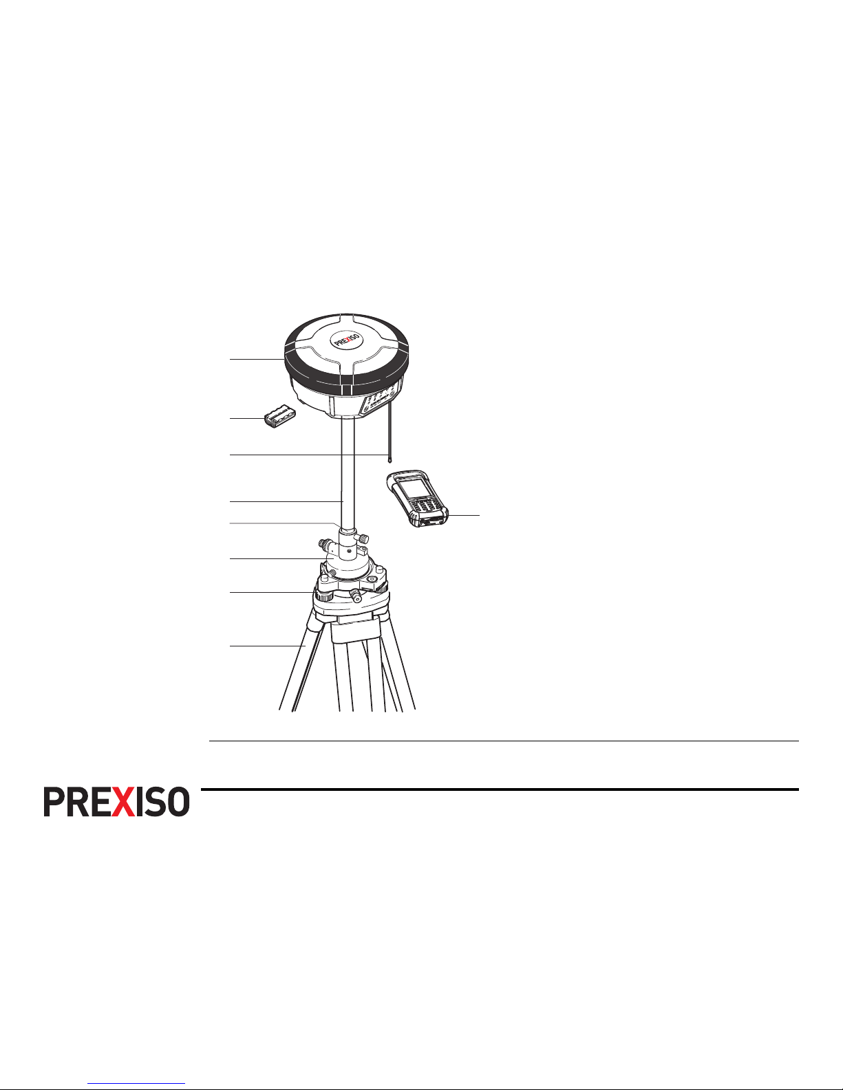
Operation G4/G5 | 21
Equipment setup G4/G5
a) G4/G5 instrument
b) PBA202 battery
c) RTK antenna
d) PPC210 base pole
e) Connection screw
f) Carrier
g) Tribrach
h) Tripod
i) Getac PPS236 handheld
i
g
a
b
c
d
e
f
h
G4/G5 | 22Operation
Equipment setup
step-by-step
Step Description
1. Set up the tripod.
2. Mount the tribrach on the tripod.
3. Ensure that the tribrach is over the marker.
4. Mount and level the carrier on the tribrach.
5. Mount the connection screw on the carrier.
6. Screw the base pole to the connection screw.
7. Insert the battery into the instrument.
8. Connect the RTK antenna to the instrument.
9. Press the ON/OFF button on the instrument for 1s to switch on the instrument.
10. Screw the instrument onto the base pole.
11. Check that the tribrach and carrier are still level.
12. Connect the handheld to the instrument through Bluetooth.
13. Measure the antenna height using the measuring tape. Refer to "3.1.7 The
Mechanical Reference Plane, MRP" for information on the antenna height.
Operation G4/G5 | 23
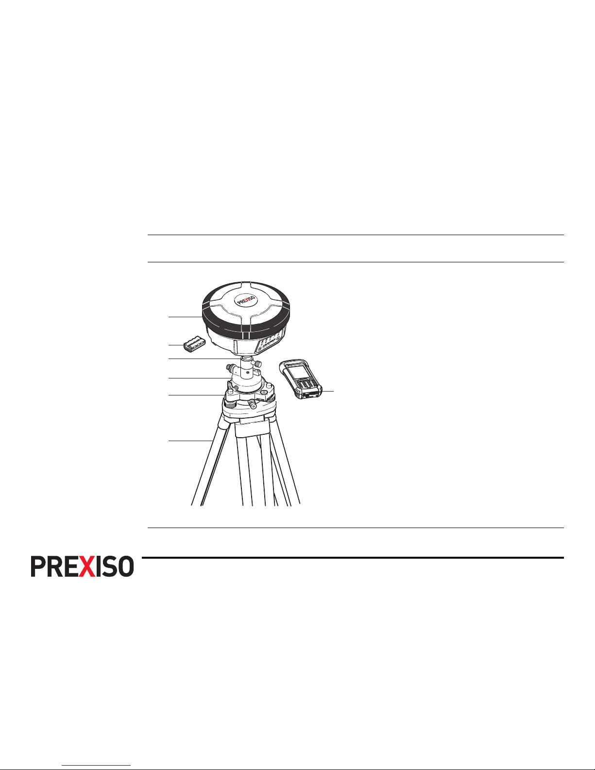
3.1.2 Setting up as a Post-Processing Base
Use The following equipment setup is used for static operations over markers.
Equipment setup G4/G5
a) G4/G5 instrument
b) PBA202 battery
c) Connection screw
d) Carrier
e) Tribrach
f) Tripod
g) Getac PPS236 handheld
g
f
a
b
c
d
e
G4/G5 | 24Operation
Equipment setup
step-by-step
Step Description
1. Set up the tripod.
2. Mount the tribrach on the tripod.
3. Ensure that the tribrach is over the marker.
4. Mount and level the carrier on the tribrach.
5. Mount the connection screw on the carrier.
6. Insert the battery into the instrument.
7. Press the ON/OFF button on the instrument for 1 s to switch on the instrument.
8. Screw the instrument onto the connection screw.
9. Check that the tribrach and carrier are still level.
10. Connect the handheld to the instrument through Bluetooth.
11. Measure the antenna height using the measuring tape. Refer to "3.1.7 The
Mechanical Reference Plane, MRP" for information on the antenna height.
Operation G4/G5 | 25
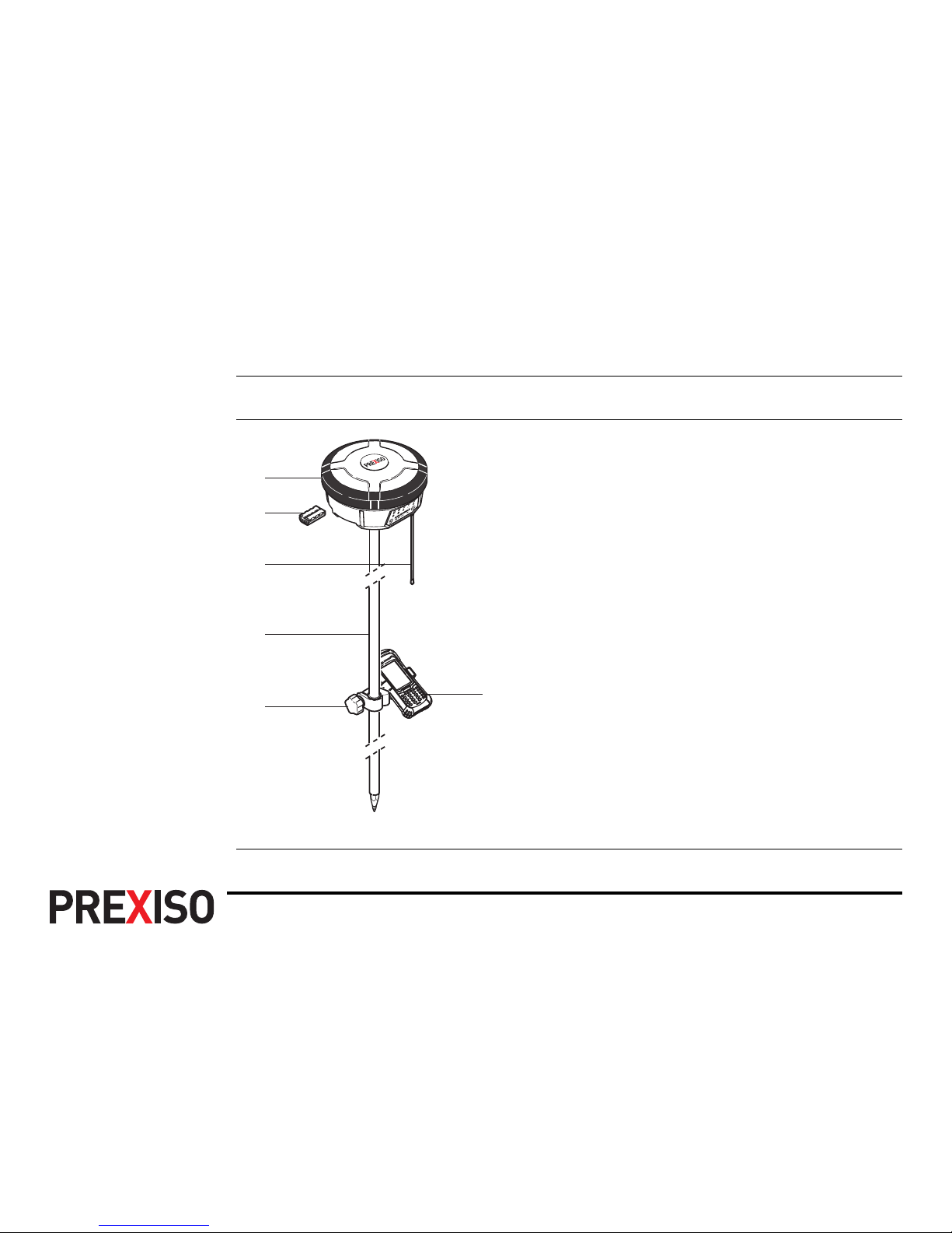
3.1.3 Setting Up as a Real-Time Rover
Use The following equipment setup is used for real-time rover.
Equipment setup G4/G5
a) G4/G5 instrument
b) PBA202 battery
c) RTK antenna
d) PPC200 pole
e) Pole holder
f) Getac PPS236 handheld
f
a
b
c
d
e
G4/G5 | 26Operation
Equipment setup
step-by-step
Step Description
1. Attach the pole holder to the ZPC200 pole. Refer to "3.1.4 Fixing the handheld to a holder and pole".
2. Clip the handheld into the holder and lock it by tighten the screw on the
holder.
3. Turn on the handheld.
4. Insert the battery into the instrument.
5. Connect the RTK antenna to the instrument.
6. Press ON/OFF button on the instrument for 1 s to switch on the instrument.
7. Screw the instrument to the top of the pole.
8. Connect the handheld to the instrument through Bluetooth.
Operation G4/G5 | 27
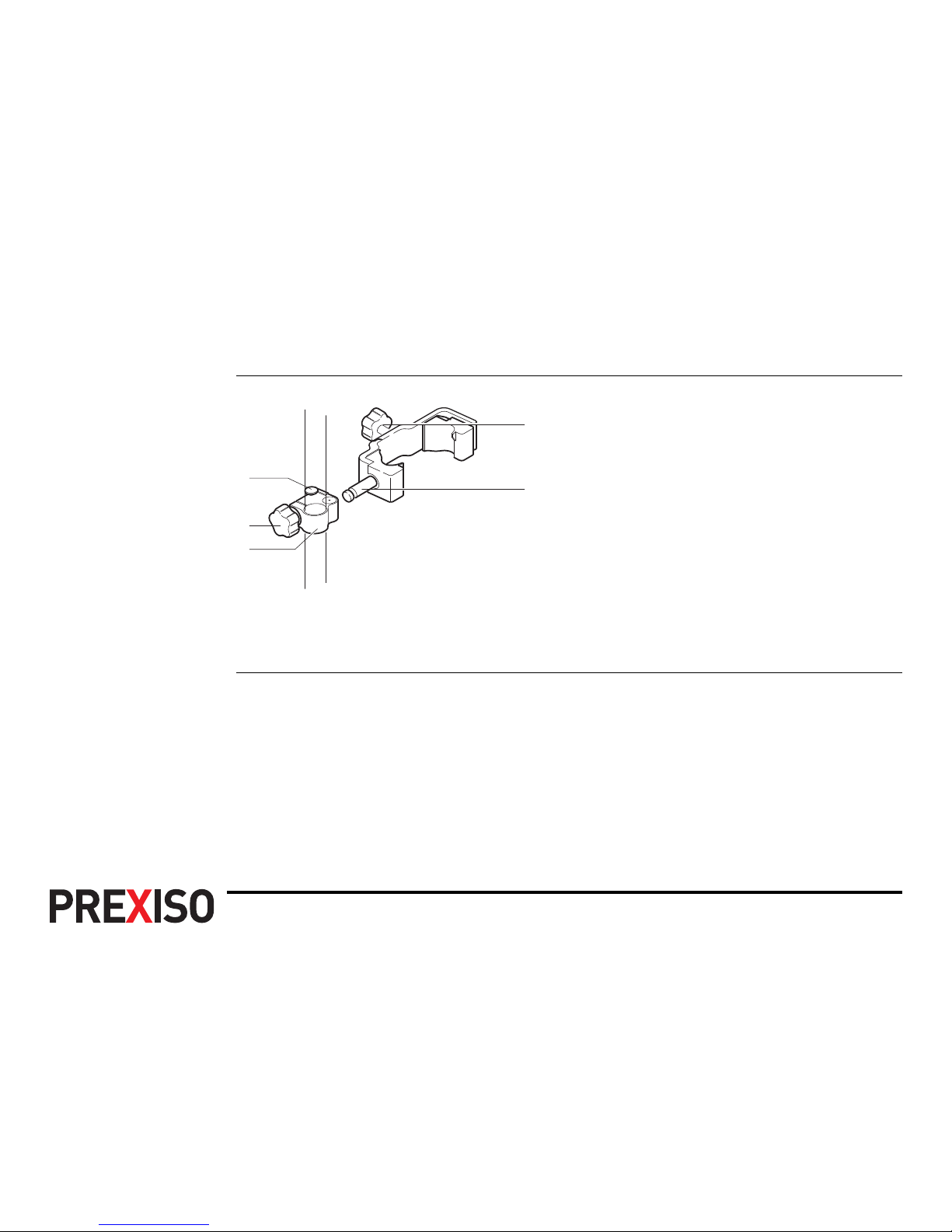
3.1.4 Fixing the handheld to a holder and pole
Components of the
pole holder
Clamp
a) Locking pin
b) Tightening screw
c) Pole clamp
Holder
d) Tightening screw
e) Pin
a
b
c
e
d
Zenith20_017
 Loading...