

Page 1
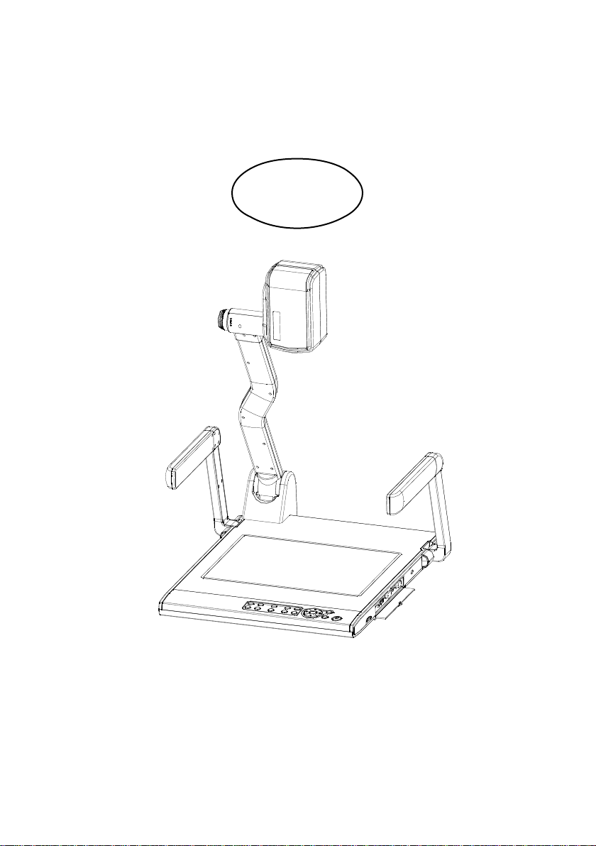
View Tech Desktop Visualizer
VT-666
User Manual
Page 2

Page 3

Page 4

PRECAUTIONS
Please follow these precautions:
To prevent fire or shock hazard, do not expose the unit to rain or moisture.
To prevent electrical shock, do not open the cabinet. Refer to qualified
personnel for service only.
Do not use the unit continuously for more than 24 hours with camera auto
focus on. It may cause damage to the camera lens.
Be careful not to spill water or other liquids onto the unit, or allow combustible
or metallic objects to get inside the cabinet.
Unplug the visualizer from the wall outlet when it is not in use for
an extended period of time.
Clean cabinet with a soft cloth lightly moistened with a mild detergent.
Clean lens carefully with an air spray or soft dry cloth to avoid scratching.
When lamps flash or become dark, they should be replaced with new ones.
Avoid interchanging arm lights and back light frequently.
Remove the camera lens cap before power the unit on.
1
Page 5

CONTENTS:
PARTS IDENTIFICATION ................................................................................. 3
CONTROL PANEL ............................................................................................ 3
BUTTON INSTRUCTION .................................................................................. 4
REMOTE CONTROL ........................................................................................ 5
CONNECTIONS ................................................................................................ 6
BASIC PREPARATIONS ................................................................................... 7
PAL/NTSC VIDEO OUTPUTS ........................................................................ 10
WORKING ON THE STAGE ........................................................................... 10
WORKING OUTSIDE THE STAGE ................................................................ 10
LIGHT .............................................................................................................. 11
ADJUSTING IMAGE SIZE .............................................................................. 11
WORKING WITH NEGATIVES ....................................................................... 12
FOCUSING ..................................................................................................... 12
FREEZING IMAGE ......................................................................................... 12
BRIGHTNESS ADJUSTMENT ........................................................................ 12
WHITE BALANCE ADJUSTMENT .................................................................. 12
AUTO ADJUSTMENT ..................................................................................... 13
TEXT/IMAGE MODE ....................................................................................... 13
COLOR AND B&W MODE SWITCH............................................................... 13
COMPUTER / VIDEO INPUTS ....................................................................... 13
PROJECTOR ON/STANDBY .......................................................................... 13
PROJECTOR INPUTS SELECTION .............................................................. 13
IMAGE ROTATION .......................................................................................... 14
IMAGE REVERSION ...................................................................................... 14
INFRARED REMOTE CONTROL ................................................................... 14
4 X 4 MULTIPLE SCREEN DISPLAY ............................................................. 14
INSTALLING VISUALIZER SOFTWARE ........................................................ 15
USB PORT ...................................................................................................... 15
USB IMAGE CAPTURE .................................................................................. 16
CONTROLLING VISUALIZER BY COMPUTER ............................................ 17
CONTROLLING PROJECTOR BY VISUALIZER ........................................... 17
FOLDING THE UNIT ....................................................................................... 21
SPECIFICATIONS ........................................................................................... 22
2
Page 6
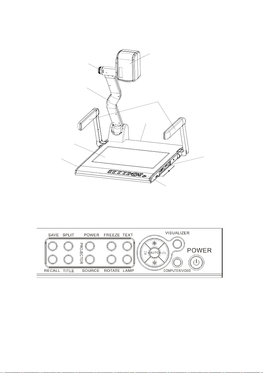
PARTS IDENTIFICATION
Zoom in/out knob
Camera
Stage
Camera stand
Arm lights
Connectors
Back light
Remote control slot
Connectors
Operation panel
CONTROL PANEL
SAVE (Save captured images)
RECALL (Multiple Screen Display)
SPLIT (Image Split function)
TITLE (Freeze the top 1/8 of the screen)
PROJECTOR POWER (Control the projector On/Standby)
PROJECTOR SOURCE (Projector input signal selection)
3
Page 7
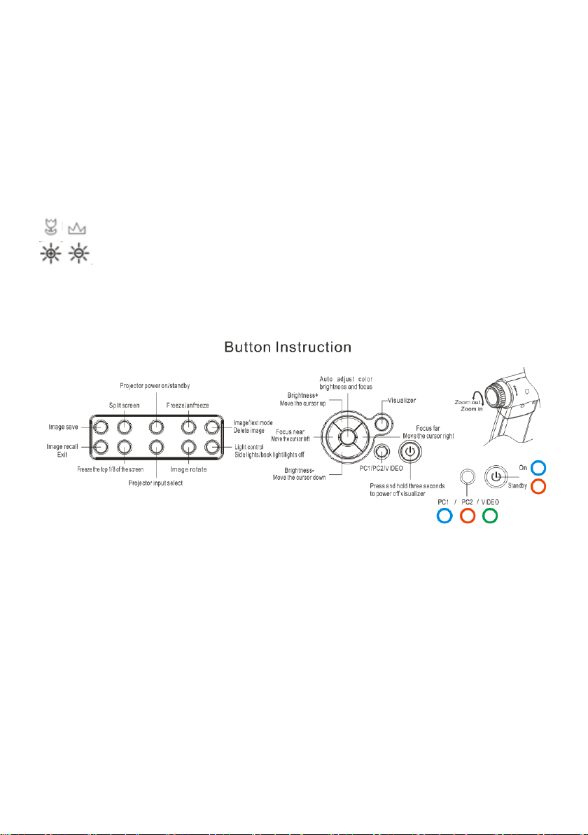
FREEZE (Freeze the image)
ROTATE (Rotate the image)
TEXT (Switch between image/text mode)
LAMP (Control the arm lights and back light)
POWER (Control the visualizer On/Off)
VISUALIZER (Camera signal output selection)
COMPUTER/VIDEO (Computer/ Video input signal selection)
AUTO (To auto white balance and auto focus)
/ (Focus near or far)
/ (Increase or decrease the brightness)
BUTTON INSTRUCTION
Note: 1.When the indicator is mixed color(red and blue),camera signal output
from PROJECTOR port.
2.When the indicator is mixed color(red and green),camera signal
output from VIDEO or S-VIDEO port.
4
Page 8
REMOTE CONTROL
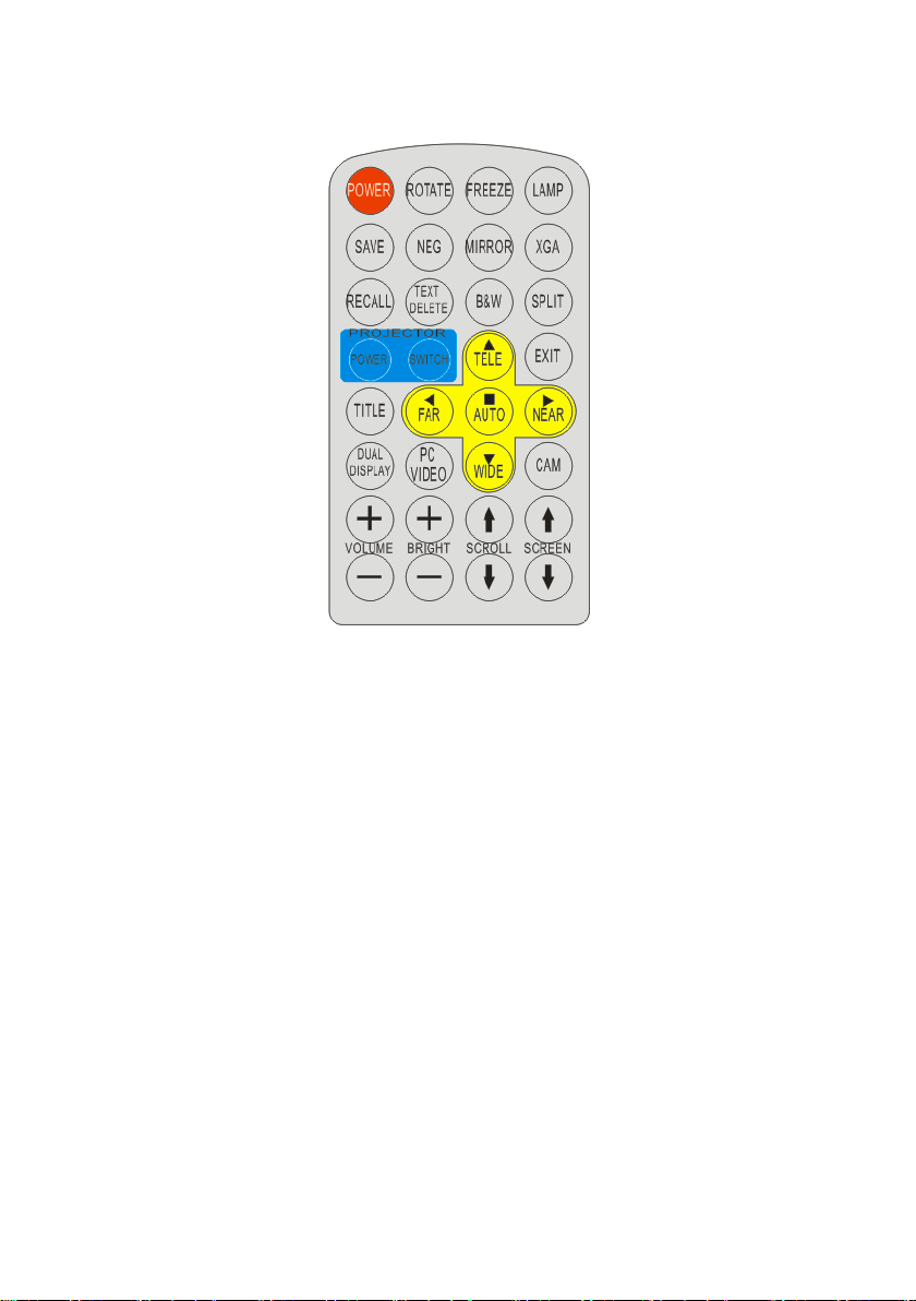
POWER (Control the visualizer On/Off)
ROTATE (Rotate the image)
FREEZE (Freeze the image)
LAMP (Control the arm lights and back light)
SAVE (Save captured images)
NEG (Display film negatives)
MIRROR (V-Reverse the image)
XGA (Switch among XGA , SXGA, WXGA and 720P)
RECALL (Multiple screen display)
TEXT/DELETE (Switch between image/text mode, delete image under recall
mode)
B&W (Switch between Color mode and Black & White mode)
SPLIT (Image Split function)
PROJECTOR POWER (Control the projector On/Standby)
PROJECTOR SWITCH (Projector input signal selection)
EXIT (Exit selected function)
5
Page 9
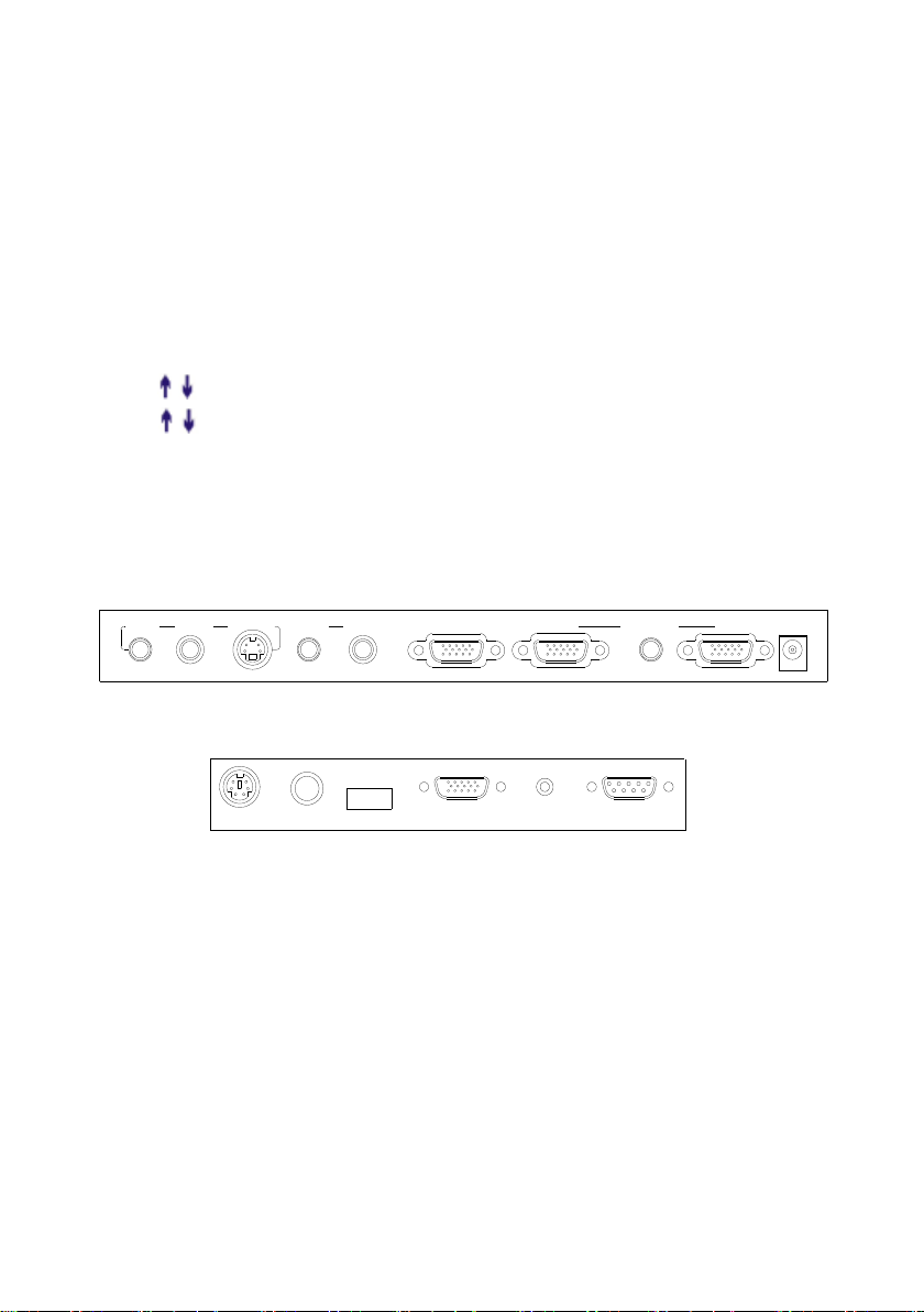
TITLE (Freeze the top 1/8 of the screen)
Rear Panel
USBMIC RGB IN AUDIO IN RS232
PROJECTOR
Side Panel
INOUT
AUDIO IN
COMPUTER PROJECTOR
IN
VIDEO
AUDIO
VIDEO
AUDIO
OUTOUT
S-VIDEO
12V- IN
1
2 3
4
5
6
7
8
9
10
11 12
13
14
15
16
TELE/WIDE (Increase and decrease magnification)
FAR/NEAR (Focus near or far)
AUTO (To auto white balance and auto focus)
DUAL DISPLAY(*No function)
PC/VIDEO (Computer/Video input signal selection)
CAM (Visualizer output selection)
VOLUME+/- (Increase or decrease the volume)
BRIGHT+/- (Increase or decrease the brightness)
SCROLL / (*No function)
SCREEN / (*No function)
CONNECTIONS
#1 AUDIO OUT #2 VIDEO OUT #3 S-VIDEO OUT
#4 VIDEO AUDIO IN #5 VIDEO IN #6 PROJECTOR Connector
#7 COMPUTER OUT #8 COMPUTER AUDIO IN
#9 COMPUTER IN #10 POWER IN
#11 PROJECTOR RS232 Connector #12 MIC IN
#13 USB Connector #14 RGB IN
#15 RGB AUDIO IN #16 COMPUTER RS-232 Connector
6
Page 10
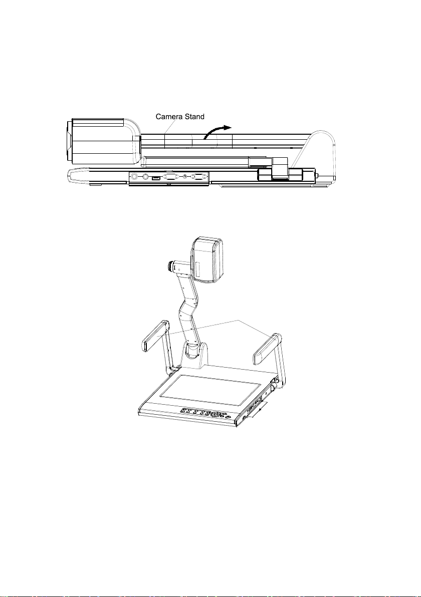
BASIC PREPARATIONS
Arm lights
1. Place one hand firmly on the base of the visualizer, while carefully
lifting up the camera stand using the other hand.
2. Open the arm lights and rotate the camera head until they are properly
positioned.
3. Making connections:
Before making any connections, turn off all the power. Please ensure that
the visualizer along with all other equipments to be connected are turned
off.
Step 1: Connect power source.
First connect the power cord to the 12V IN connector.
7
Page 11
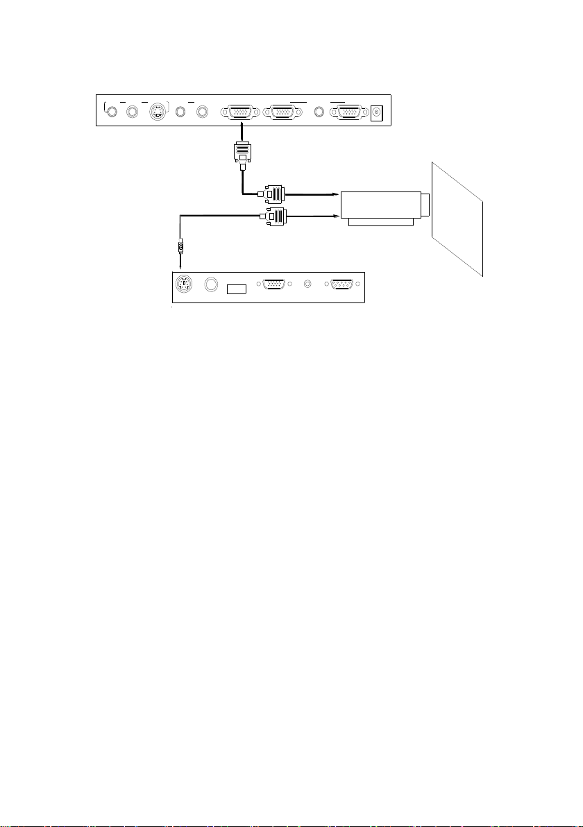
Step 2: Connect to the projector.
Projector
RGB Input
Screen
RS232 Cable
Rear Panel
USB
MIC RGB IN AUDIO IN
RS232
PROJECTOR
Side Panel
INOUT
AUDIO IN
COMPUTER PROJECTOR
IN
VIDEO
AUDIO
VIDEO
AUDIO
OUTOUT
S-VIDEO
12V- IN
1
2 3
4
5
6
7
8
9
10
11 12
13
14
15
16
Connect the PROJECTOR port to the projector‟s RGB IN port using the
RGB cable. You can also control a projector using the controls on the
visualizer by connecting the projector to the visualizer using a 6-pin to 9-pin
RS232 cable. Some projector models may require a converter cable in
addition to this standard RS232 cable to connect to the projector control
port, for the pin locations and shape of some projectors‟ control port
connector may be different from the connector of a standard RS232 cable.
Once the visualizer is connected to the projector, you can control the
projector‟s power on, standby and input selection by using the visualizer.
(Aside from Hitachi projectors, the Code Writing program that comes with
the visualizer is required to access this function.)
8
Page 12
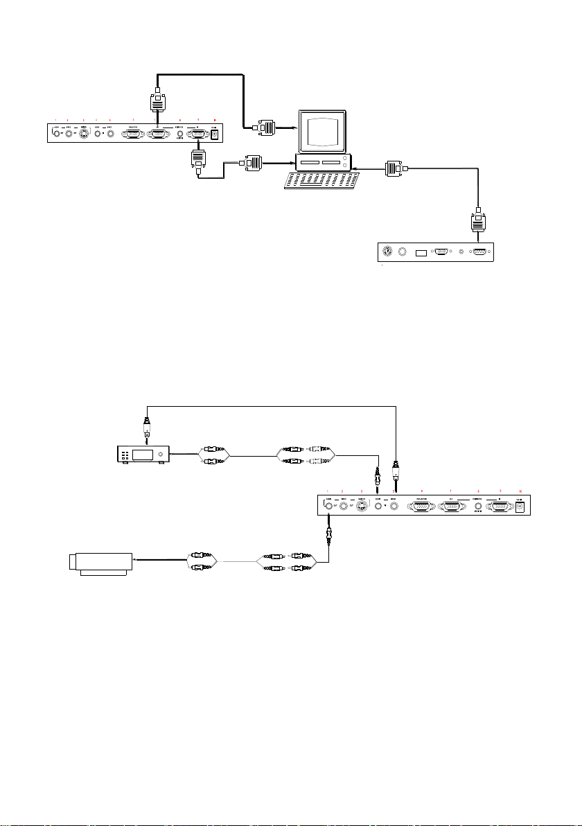
Step 3: Connect to a desktop computer.
Rear Panel
11
USB
PROJECTOR
MIC
15
RGB IN AUDIO IN
RS232
Side Panel
12 13
14
16
RS232
Cable
Computer
To the
Monitor
RGB Output
Video Cable
Projector
(or amplifier/speaker equipment)
Audio input
Audio out
Video out
Video equipment
Rear Panel
Note: You can connect a laptop computer to the RGB IN port of side panel
using a RGB cable.
Step 4: Connect to the video equipment.
9
Page 13
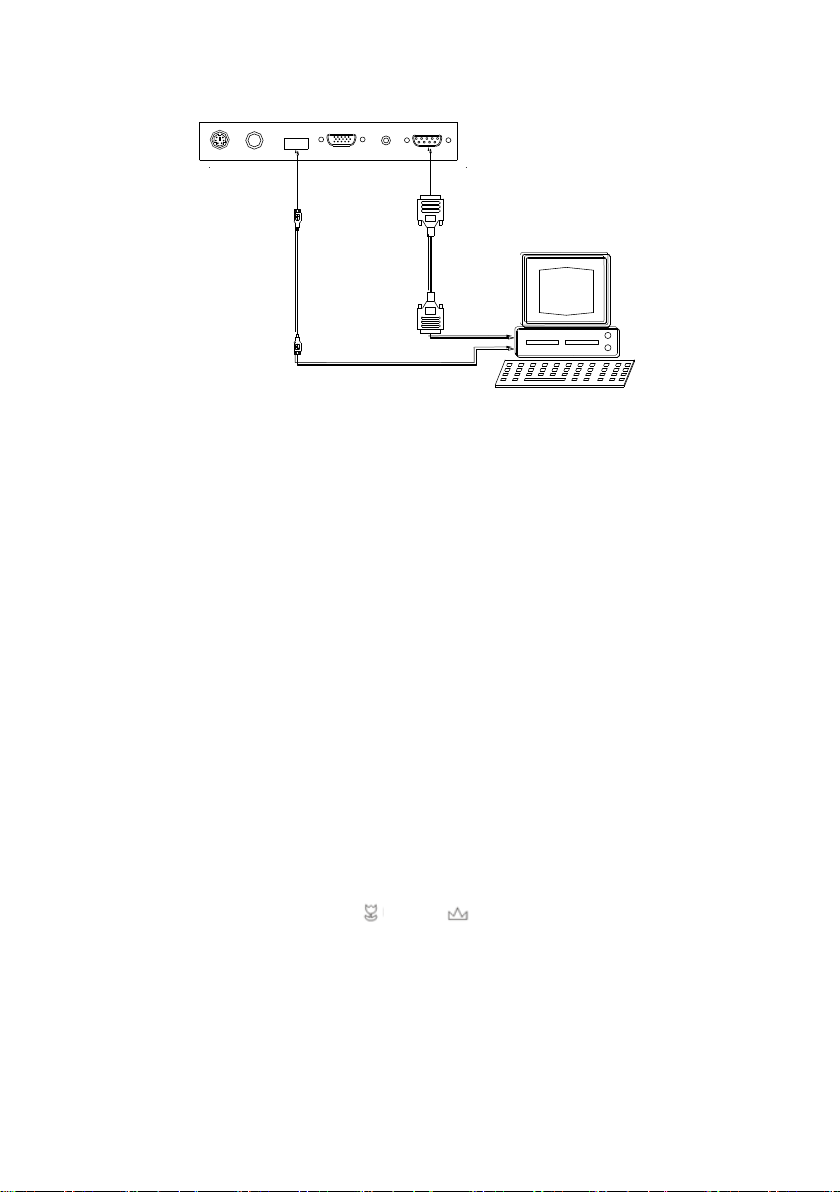
Step 5: Connections for external control from the computer.
RS 232 connector
USB connector
of the computer
of the computer
USB cable
RS-232 cable
Side Panel
USB
PROJECTOR
MIC
RGB IN AUDIO IN
RS232
11
12
13
14 16
15
Use the computer RS232 cable (9-pin to 9-pin) to make the
connections displayed below to control the visualizer from an external
computer.
A USB connection enables the computer to capture still images and/or
video streams from the visualizer. Special software is required for this
operation.
4. Turn on the power by pressing the “POWER” button.
PAL/NTSC VIDEO OUTPUTS
The S-Video and composite video outputs are set to PAL (NTSC) during
manufacturing.
WORKING ON THE STAGE
1. Place your material on the platform.
2. Select the enlargement required using the Zoom in/out knob.
3. Adjust the focus using the “ ” and “ ” buttons or “AUTO” button.
WORKING OUTSIDE THE STAGE
To show a 3-dimensional object using the visualizer, place the object on the
working surface and adjust the Zoom in/out knob and “AUTO” keys. If the
object is too large for the stage or if you would like to show it from one of its
10
Page 14
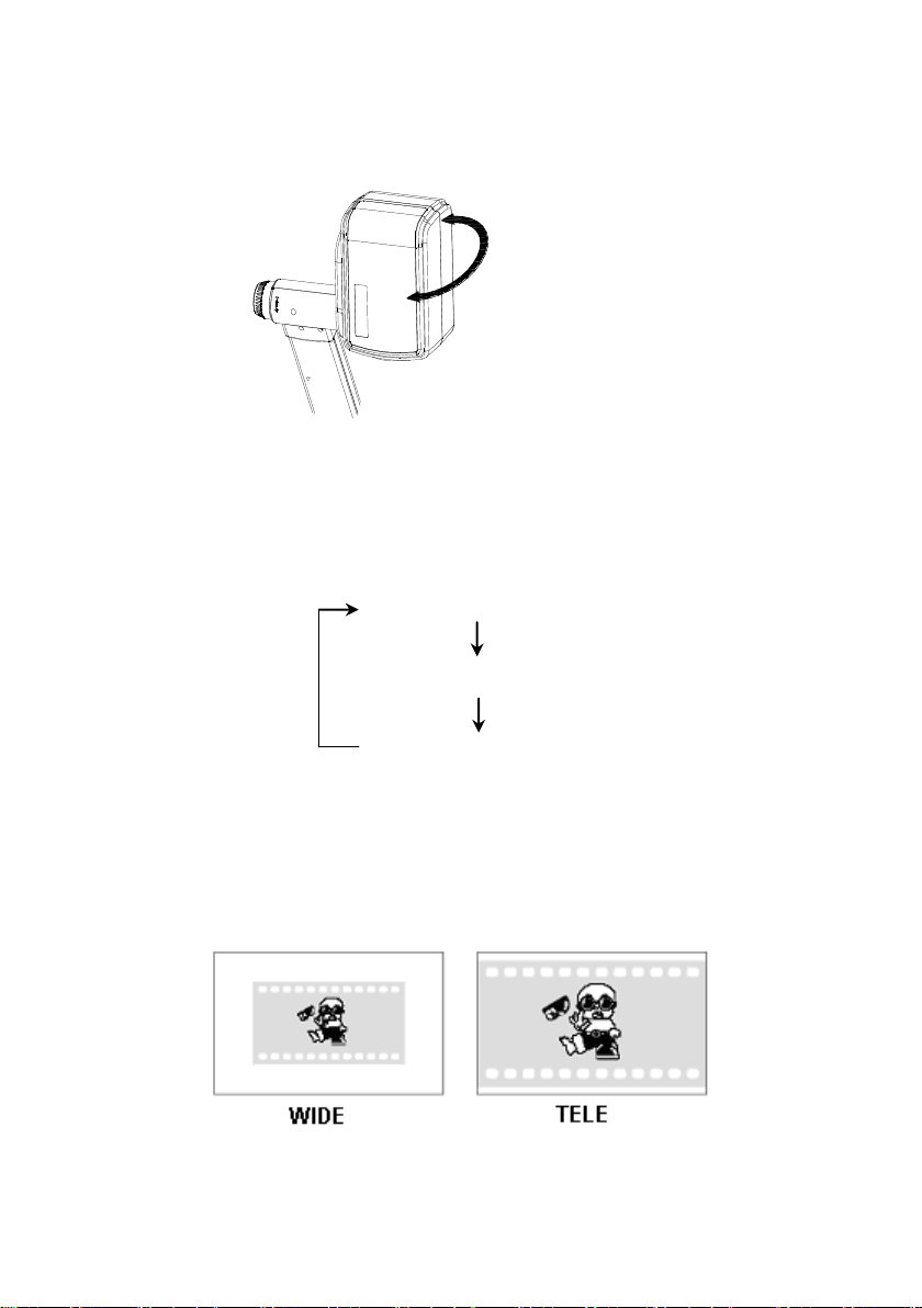
side, or a different angel, just place the object behind or in front of the unit
Rotate 330 degrees
vertically
and manually tilt the camera head (remove the close-up lens prior to titling
the camera head).
LIGHT
The arm lights are powered on when the power is turned on. Each time you
press the “LAMP” buttons, the lighting changes occur as demonstrated.
The arm lights turn on
The back light turns on
All the lights turn off
ADJUSTING IMAGE SIZE
To reduce or enlarge the image size displayed on the screen, rotate the
Zoom in or Zoom out knob.
11
Page 15
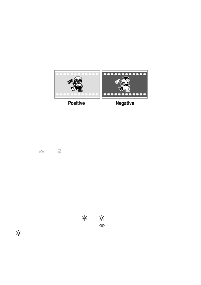
WORKING WITH NEGATIVES
The visualizer is automatically set to display normal materials on the
screen when the power is on. To display negatives, turn on the backlight by
pressing the “LAMP” key, and then press the “NEG” button to display the
film negatives. Press the “NEG” button again to display normal materials in
the color mode.
FOCUSING
When the visualizer is turned on the focus automatically adjusts to the
stage, Only 3D objects require a focus adjustment.
Press the “AUTO” button to auto focus.
Press the “ ” or “ ” button to focus manually.
FREEZING IMAGE
To show a still image on the screen, when the output signal is RGB, press
the “FREEZE” button. The frozen image cannot be adjusted (Zoom in/out,
color adjustment, etc.).
BRIGHTNESS ADJUSTMENT
If the image effect is not satisfactory, you can adjust the brightness to get a
better image effect. Use the “ ” or “ ” button to adjust the brightness. To
increase the brightness, press the “ ” button. To decrease it, press the
“ ” button.
WHITE BALANCE ADJUSTMENT
Each time the lighting condition changes, the user should adjust the white
12
Page 16

balance of the CAM.
Press the “AUTO” button to adjust the white balance automatically.
AUTO ADJUSTMENT
One of the visualizer‟s special functions is auto adjustment. Press the
“AUTO” button to auto adjust the brightness, the white balance and the
focus.
TEXT/IMAGE MODE
Press the “TEXT” button to switch between image/text modes. To display a
text file, switch to the text mode to get a clearer text effect.
COLOR AND B&W MODE SWITCH
Press “B&W” once to enter the Black & White mode; press again to return
to the Color mode. (On the remote control)
COMPUTER / VIDEO INPUTS
Press the “COMPUTER/VIDEO” button to switch between computer and
composite video signals. Each time the “COMPUTER/VIDEO” button is
pressed, it provides seamless transitions among different sources such as
COMPUTER (IN), and RGB (IN),VIDEO(IN).
Notes: COMPUTER OUT always outputs COMPUTER IN signals. VIDEO
IN just can be output from S-VIDEO OUT or VIDEO OUT. COMPUTER IN
and RGB IN just can be output from PROJECTOR port.
PROJECTOR ON/STANDBY
Press the “POWER” button to turn on the visualizer‟s power and press the
“PROJECTOR POWER” button to turn the projector power on. To place the
projector on standby after the use, press the “PROJECTOR POWER”
button and hold for more than 2 seconds.
PROJECTOR INPUTS SELECTION
When the projector is connected to several input sources, use the
13
Page 17
“PROJECTOR SOURCE” button to switch between projector signal inputs.
(Using the remote control, press the “PROJECTOR SWITH” button)
IMAGE ROTATION
In order to rotate the image, press the “ROTATE” button once, the
displayed image will be rotated 90,180,270 degrees clockwise. Continue
to press the “ROTATE” button to restore the image to its initial position.
IMAGE REVERSION
To display a vertically mirrored image, press the “MIRROR” button. Press
the “MIRROR” button again to exit.
INFRARED REMOTE CONTROL
The visualizer‟s remote control can control the camera from different
angels. On the left side of the visualizer stage, there is a built-in remote
control storage compartment where you can store the remote control when
it is not in use.
Please note that an infrared remote control can only be used up to a
certain distance to the unit. Objects situated between the visualizer and the
infrared remote control and a weak battery may interfere with the reception.
4 X 4 MULTIPLE SCREEN DISPLAY
Press “RECALL”, the stored images can be displayed in a 4 x 4 matrix.
Use , , , button to Select the image that you want to display,
then click button to display the selected image, press “TEXT” button
to delete the selected image. Press “RECALL” to exit the 4 x 4 image
display mode.
On the remote control, the “RECALL”,“ ”, “ ”, “ ”, “ ”, “ ” and “TEXT”
button can do the operation. Press “EXIT” to exit the 4 x 4 image display
mode.
14
Page 18

INSTALLING VISUALIZER SOFTWARE
This function is to snap and display images with the USB interface, which
includes displaying static and dynamic pictures, snapping dynamic images and
playback the dynamic images with the Windows Media Player or its own
player.
A. Insert the CD-ROM that comes with the visualizer into the CD-ROM drive.
If Autorun is enabled on your system, then the Software Setup window will
be displayed automatically as below.
If it does not start automatically, after inserting the CD-ROM, Click [Start]
[My Computer], and double click (the CD-ROM drive letter might
be different in different computer systems), and then the above screen will
appear immediately.
B. Click the Capture Program file to install the program that captures
images in the AVI or JPG format.
C. Click the Code-Writing Program file to install Code-Writing Program.
D. Shut down your computer when prompted in order for the changes to take
effect.
E. Use the USB2.0 cable provided to connect your computer to the visualizer
before your computer is restarted.
USB PORT
The USB port can be used to store still images from the visualizer in a
computer. Connect the visualizer to your computer with the supplied USB
cable. The visualizer software is available on the supplied CD-ROM.
* Please pay attention to the following:
1. Computer hardware requirement: CPU: 2.4GHz, RAM: 256M or above,
Graphic card 64M, USB 2.0 port, Hard disk 40G or more, Monitor
display resolution higher than XGA (1024x768).
2. Operating system: Windows XP SP2 ,Win7.
3. Must use a high-speed USB 2.0 cable provided .
15
Page 19
4. When connecting the visualizer to a desktop computer with the
high-speed USB 2.0 cable provided, we recommend using the USB
port located on the rear of the mainframe. The USB port on the front
of the computer might have interference.
USB IMAGE CAPTURE
You can capture and control images on the visualizer from a computer
connected with a USB connector.
Click [Start] [Program] [VideoCap] “VideoCapx.xx” (x.xx is
software‟s version) to open the software.
A. Static Images Snap
Click “Capture”“Capture Frame”, input the file name in dialog box, or you
can click icon on the toolbar, then input file name in dialog window. The
image file is JPG format.
B. Snap Video Stream
Click “Capture” “Start Capture”, input the file name in dialog box, or click
icon on the toolbar, then input the file name in dialog box. If you want to
set the time limit for the capture, select “Capture” “Set Time Limit“ to set
the time limit. Click “Start Capture” to start capture, and click “Stop
Capture” or icon on the toolbar to stop capture. (If you have set the
time limit, it will stop automatically when the time is up.) The video file is
AVI format.
C. Set the Frame Rate
Click [Capture] [Set Frame Rate], and click open “Choose Frame Rate”
to set the frame rate.
D. Set Time Limit
Click [Capture] [Set Time Limit] to set the time limit while capturing
16
Page 20

video.
E. Note:
Do not connect / disconnect the USB cable when the application is running,
which will cause the program to be interrupted.
CONTROLLING VISUALIZER BY COMPUTER
You can control the visualizer from a computer connected with a RS232
connector.
A. Connect the computer and the visualizer using the RS232 cable.
B. Double click X:\ 232 Control\Control Panel (you can open this file from
the CD and double click it, or copy this file to any directory on your
computer‟s hard drive and double click to launch it).
CONTROLLING PROJECTOR BY VISUALIZER
The code writing software is used to inputting projector‟s control code, then
can control various projector with the visualizer.
1. Click the Code-Writing file to install Code-Writing Program.
2. Connect the visualizer to the projector with the RGB、VIDEO、S-VIDEO
cables.
3. Connect the RS232 cable to the computer‟s connector. The visualizer‟s
RS232 port is located on its right side.
4. After completion of the connection, turn on the visualizer,click [start] ->
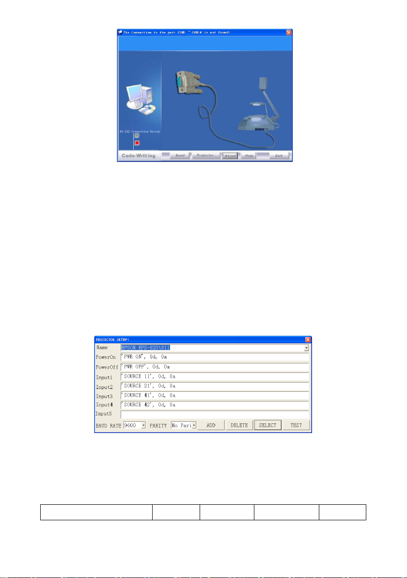
[All Programs] -> Visualizer -> and the following
dialog box appears as below:
17
Page 21
BE EF 03 06 00
BA D2
01 00
00 60
01 00
When the indicator of “Current RS-232 Connection Status” is green, that
means the connection between the visualizer and the computer‟s RS232
connector is good. If the indicator is red, please check if the RS232 cable is
connected correctly. When all the cables are connected correctly, please
click “Projector” to select your projector model under the drop-down list,
then click “Send”. If you can not find your particular projector model in the
“Projector”, please do the following:
1).Select “Baud rate” and “parity” and input the projector control code.
(The baud rate, parity and control code is supplied by projector‟s
manufacturer, please refer to the projector‟ manual)
The input format of projector‟s control code is as follows:
a. If the data is in the numerical value format, please input data directly,
block them off with comma, do not distinguish lowercase and uppercase.
For example: the “POWER ON” code in Hitachi projector manual is :
In the POWRE ON box,Input : be, ef, 03, 06, 00, ba, d2, 01, 00, 00, 60, 01,
18
Page 22
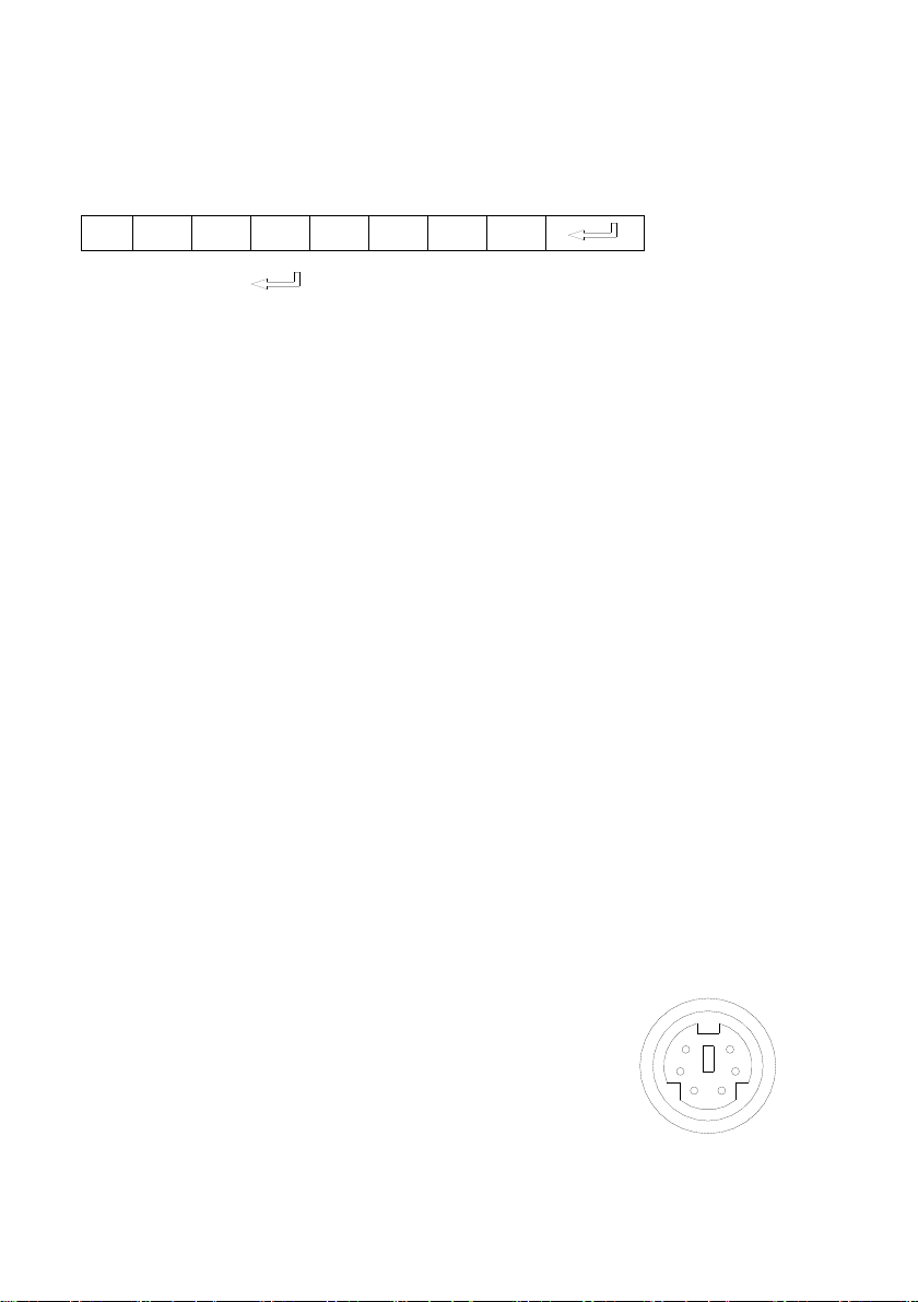
00. Then use the same input rule to input other code.
P O W R - - -
1
6
5
4
3
2
1
b. If the data is in the character string format, input „character string‟.
For example: the “POWER ON” code in the SHARP C40/50 projector
manual is :
( “-” is space, is enter.)
In the POWER ON box, input ‟POWR 1‟, 0d, 0a
(Remarks: There are 3 spaces after POWER, 0d, 0a is enter.)
Input other codes in the same way.
c. If the data is in the numerical value and character format, then
synthesize the above-mentioned formats.
3).Once done, click “Add” to add your projector model, then Click “Send”.
Afterward, click “Ok”. Now, you can use the visualizer to control your
projector.
4. Connect the visualizer‟s projector control port to the RS232 port with a
RS232 cable(Please disconnect the computer from the RS232 port first).
Then use buttons on the operation panel to control the projector.
The visualizer provides a 6-pin to 9-pin RS232 cable. If this cable does not
match to your projector‟s RS232 port, an additional RS232 cable is needed.
This additional RS232 cable can be made based on the pin location of the
projector‟s RS232 control port. The pin locations of the visualizer are: the
pin 1 is RXD (Received Data); the pin 5 is TXD (Transmitted Data); the pin
4 is GND (Ground). Other pins are not defined. The pin location information
of the projector is provided by the projector‟s manufacturer. The projector‟s
RS232 control port normally has RXD pin, TXD
pin and GND pin, the name may be different. The
parallelism of each data pin is shown as follows:
Visualizer‟s RXD pin------------Projector‟s TXD pin
Visualizer‟s TXD pin------------Projector‟s RXD pin
Visualizer‟s GND pin------------Projector‟s GND pin
19
Page 23
5. If you can not use buttons on the operation panel to control the projector,
please use Code-Writing software‟s projector control code testing function
to check if the control code is correct.
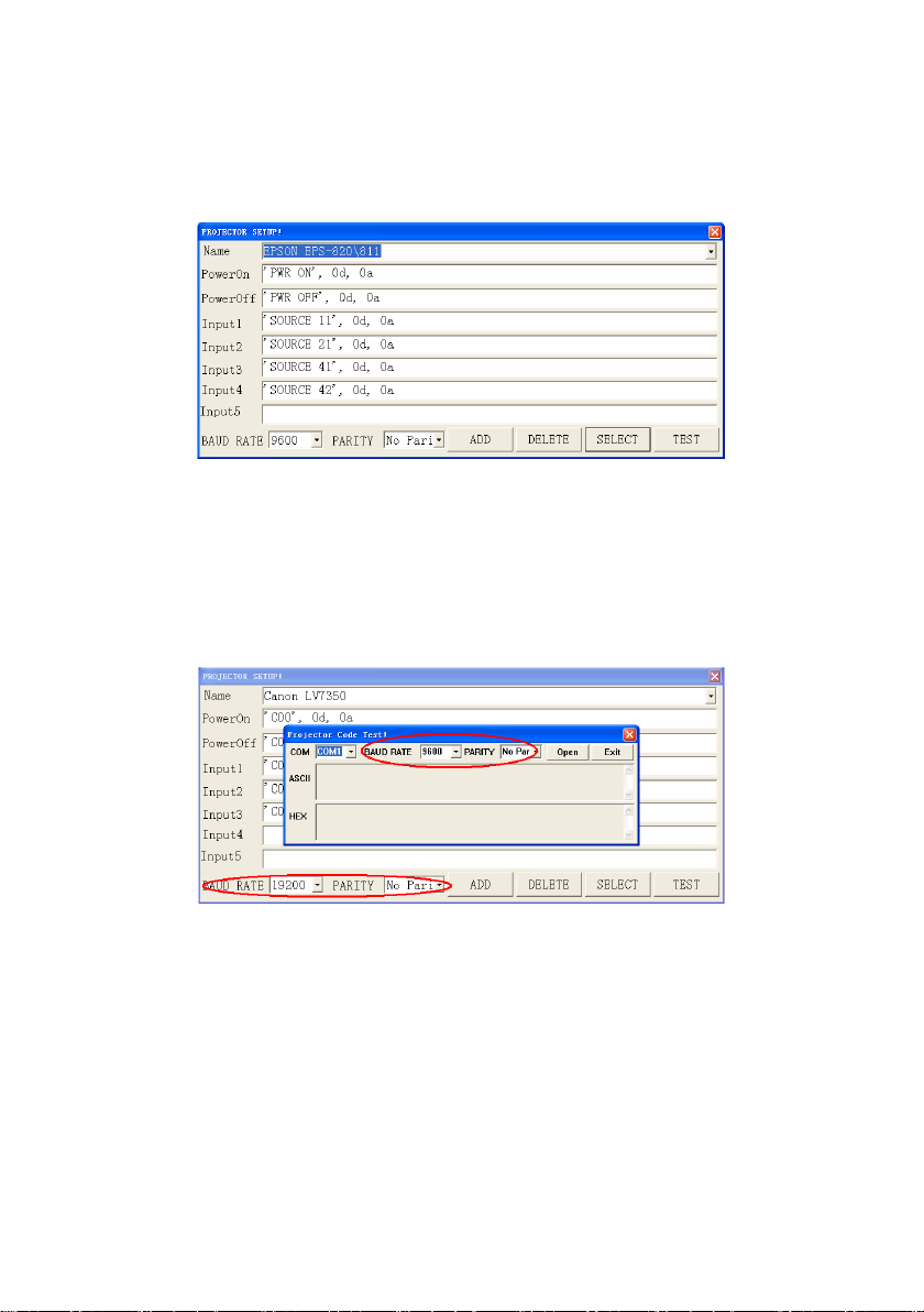
Click “Projector” button, the following dialog box appears as below:
Connect the visualizer to a computer with a RS232 cable (Please
disconnect the projector from the RS232 port first) and select the Baud
Rate and Parity based on the projector‟s Baud Rate, then click the “TEST”
button to pop up the Projector Code Test dialog box, input the Baud Rate
and Parity based on the projector‟s Baud rate, then click “Open”.
Click the projector control buttons on the visualizer‟s operating panel to
check if the control code that the program received is the same as the
sending code. If the receiving code is same to the sending code, the input
codes are correct. If the visualizer can not control the projector, please do
the following.
1. Check to see if the source control codes of projector are correct.
2. Check to make sure the connection between the visualizer and the
projector is correct.
20
Page 24
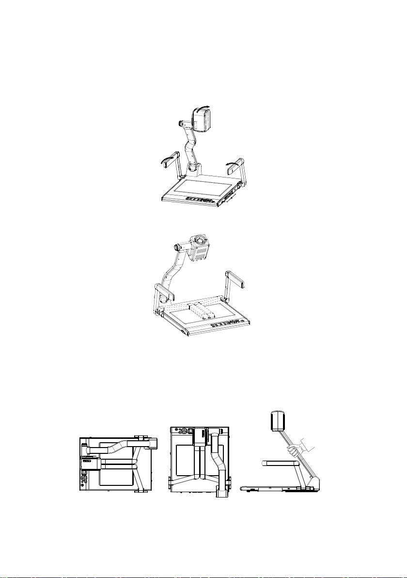
FOLDING THE UNIT
NOT THIS WAY
1. Fold the right arm light down first onto the base, then the left arm down.
Rotate the camera head clockwise until the camera head is parallel to the
camera stand.
2. Carefully fold the camera stand down to the front panel.
Cautions:
a. Do not lay the unit down flat.
b. Do not try to stand it on its rear or sides.
c. Do not try to pick up this unit by pulling the camera stand.
21
Page 25
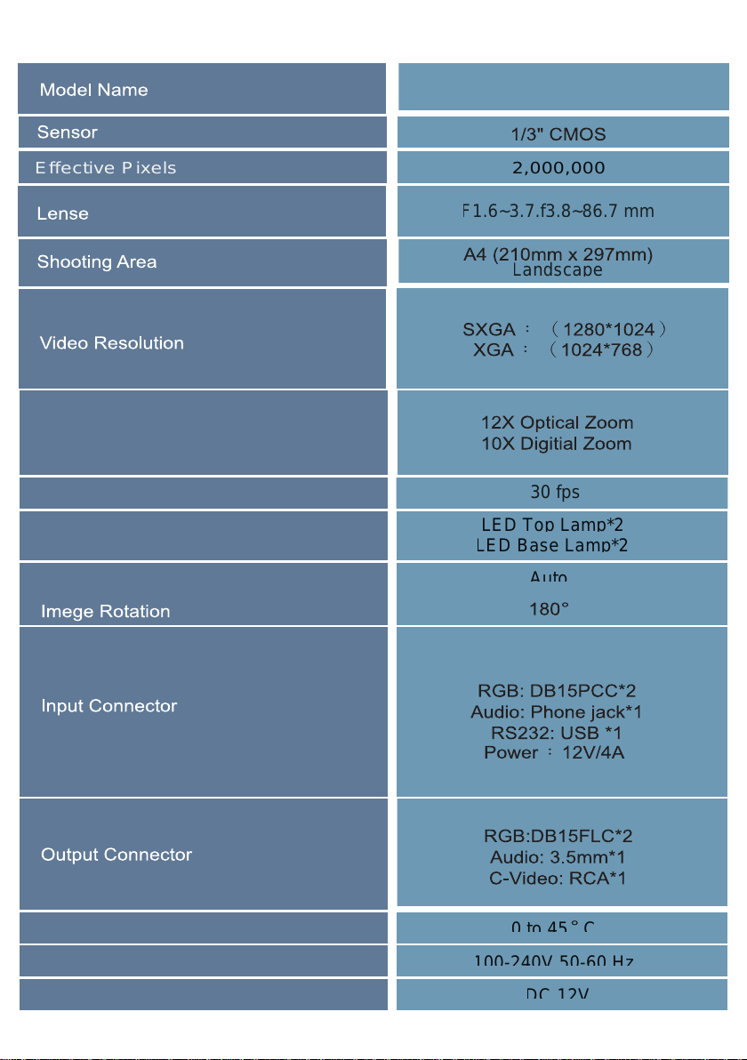
SPECIFICATIONS
VT-666
Effective Pixels 2,000,000
30 fps
22
Page 26
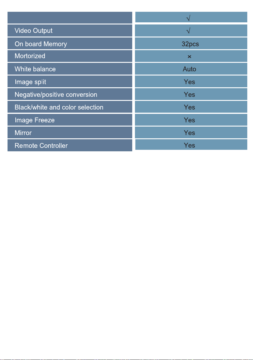
* Design and specifications are subject to change without prior notice.
23
Page 27

Page 28

Pretron Technologies Pte.Ltd.
25, Tagore Lane #04-10-2 Singapore 787602
www.pretron.com.sg/
 Loading...