

Page 1
P4
Level Loader
Model Number ___________________
Serial # _________________________
Date Placed in Service _____________
IMPORT ANT : READ CAREFULLY
BEFORE INST ALLING OR OPERA TING LIFT
Part orders are subject to a $50 miminum charge
May 2006
Page 2

INTRODUCTION
The P4 Level Loader is designed to allow faster, safer, and easier pallet loading and
unloading. Pallets may be loaded or unloaded in a single step, using a fork truck, or
hand pallet truck. Using a pushbutton or footswitch control, the operator can position
boxes or containers at a convenient working height. This allows workers to load or
unload without bending or stretching.
The unit includes a photo eye toe guard feature. A photo eye is positioned near the
front of the unit. If the operator’s toes block this photo eye, the unit stops immediately .
This manual contains instructions on the safe and proper installation, use, and
maintenance of a P4 Level Loader. Please be sure that this manual is available to
anyone who uses or services the P4 unit. Be sure that everyone who uses the P4 unit
has read this manual.
P4 Level Loaders may be used in a wide variety of industrial settings. The
instructions included in this manual are not necessarily all-inclusive, because
Presto Lifts cannot anticipate all conceivable or unique situations.
In the interest of safety, please read this whole manual carefully. Please
understand the material in the manual before you install, use, or service the P4
unit. If you have any questions about the instructions in this manual, please
contact your dealer or Presto Lifts Inc.
Presto Lift’s product warranty is shown on the rear cover of this manual. This instruction
manual is not intended to be or to create any other warranty , express or implied,
including any implied warranty of merchantability or fitness for a particular
purpose, all of which are hereby expressly excluded. As set forth more specifically
in the product warranty, Presto Lift’s obligation under that warranty is limited to the
repair or replacement of defective components, which shall be the buyer’s sole remedy ,
and Presto Lift shall not be liable for any loss, injury , or damage to persons or property ,
nor for any direct, indirect, or consequential damage of any kind resulting from the P4
Level Loader.
2 PRESTO P4 LEVEL LOADER OWNER’S MANUAL
Page 3

TABLE OF CONTENTS
INTRODUCTION...............................................................................................................2
SAFETY ........................................................................................................................4
INST ALLA TION INSTRUCTIONS ......................................................................................4
Preparation...................................................................................................... 4
Positioning the Unit .........................................................................................4
Electrical Connections .................................................................................... 5
Testing.............................................................................................................6
OPERATING INSTRUCTIONS ........................................................................................7
Safety Instructions .......................................................................................... 7
Loading the Unit .............................................................................................. 8
Raising the Platform ........................................................................................ 8
Lowering the Platform..................................................................................... 9
MAINTENANCE AND TROUBLESHOOTING ...............................................................10
Hazards .........................................................................................................10
Routine Periodic Maintenance......................................................................11
Troubleshooting Check List .......................................................................... 12
Repacking the Cylinder ................................................................................. 15
Adjusting the Chain Tension ......................................................................... 15
Ordering Replacement Parts ........................................................................16
LIST OF FIGURES
Fig. 1 Safety labels ....................................................................................................5
Fig. 2 Pinch points.....................................................................................................6
Fig. 3 Load the unit correctly..................................................................................... 7
Fig. 4. Electrical diagram ...........................................................................................8
Fig. 5. Hydraulic diagram ........................................................................................... 9
Fig. 6. Parts identification — Front view.................................................................... 12
Fig. 7. Parts identification — Rear view..................................................................... 13
Fig. 8. Hydraulic pump .............................................................................................13
Fig. 9. Down valve ....................................................................................................14
Fig. 10 Hydraulic oil specifications ........................................................................... 16
PRESTO P4 LEVEL LOADER OWNER’S MANUAL 3
Page 4

SAFETY
The safety of all persons installing, using, servicing, or working near the P4 Level Loader unit is of
paramount concern to Presto. The P4 Level Loader unit is a powerful machine with moving parts,
and is CAPABLE OF CAUSING PERSONAL INJURY IF PROPER PRECAUTIONS ARE NOT
T AKEN.
Therefore, throughout this manual, Presto has identified certain hazards which may occur in the
use of the P4 Level Loader unit, and provided appropriate INSTRUCTIONS or PRECAUTIONS
which should be taken to avoid these hazards. In some cases, Presto has also pointed out the
CONSEQUENCES which may occur if Presto’s instructions or precautions are not followed. Presto
uses the following system of identifying the severity of the hazards associated with its products:
PLEASE READ AND FOLLOW THIS INSTRUCTION MANUAL, INCLUDING ALL SAFETY
INSTRUCTIONS AND PRECAUTIONS, CAREFULLY AND COMPLETELY.
DANGER: Immediate hazard which will result in severe personal injury or death.
WARNING: Hazard or unsafe practice which could result in severe personal injury or death.
CAUTION: Hazard or unsafe practice which could result in minor personal injury or
property damage.
INSTALLATION INSTRUCTIONS
Preparation
1. Before you start to install the unit, check for
local codes and ordinances which may
apply. It is your responsibility to obtain any
necessary permits.
2. Read all of these installation instructions
carefully. Be sure to read and understand
all of the warnings.
3. The unit should be placed indoors, or
protected from the weather.
WARNING!
Protect the unit from rain or
moisture. If the electrical parts in the
power unit get wet, workers may be
hurt by electrical shock. The
electrical parts may fail if they are
wet.
WARNING!
The electric motor can create
sparks. Don’t install the unit in an
area where flammable gases may be
present.
4. You will need these tools to install the unit:
• A crane or lift truck that can lift the unit safely .
If you plan to lag the unit in place, you will
need these tools:
• Shims and lag bolts.
• A masonry drill and bit to drill the holes for the
lag bolts.
• Wrenches to fit the lag bolts
• Grouting material to fill any spaces under the
frame of the machine.
Positioning the Unit
1. Remove the shipping material. Unbolt the
lag screws at the lag angles on the corners.
(If you plan to bolt the unit in place, leave the
lag angles attached to the frame of the unit.
Otherwise, unbolt and remove the lag
angles.)
2. On the front of this manual, write down the
model number , serial number , and date the
unit is placed in service. You can find the
model number and serial number on the
name plate.
4 PRESTO P4 LEVEL LOADER OWNER’S MANUAL
Page 5
3. During shipping, the platform of the unit is
raised 5-1/2", and this platform is supported
on two pins. This allows a space under the
platform. When you want to move the unit,
put a pallet jack under the platform and lift
the unit. This is the best way of moving the
unit.
CAUTION!
If you place the unit on a surface
which is not firm or level, the
unit may shift as it operates. Y ou
may be hurt, or the unit or load
may be damaged.
CAUTION!
Always raise the platform and insert
the pins before you move the unit. If
you try to move the unit in another
way , the frame may be bent. Be sure
to remove the pins before you
operate the unit. If you do not do
this, the unit may be damaged. Once
the unit has power, raise the plat form
just a bit to take the load off of the
pins, then remove the pins.
4. The unit has an 10' power cord. Choose a
location where the cord can reach an outlet
easily , without stretching the cord tightly.
5. Move the unit into position, supporting the
platform of the unit. Place the unit on a firm,
level surface.
6. The unit may be operated without bolting
the frame to the floor. However, the
mounting arrangement is more secure if
you use lag screws. Bolt the unit to the
floor using four lag bolts. These should run
through the lag angles at the corners of
the base frame. Insert and tighten the lag
bolts to secure the unit. Grout under the
base rails to prevent vibration and distortion
of the base frame.
Electrical Connections
DANGER!
The unit uses a power supply of 115
volts AC. This voltage can kill you.
Don’t work with the electrical parts
unless you are a qualified electrician.
PRESTO P4 LEVEL LOADER OWNER’S MANUAL 5
Page 6
1. The unit is supplied with a power cord which
is 10' long. You must provide a two-prong
outlet within this distance from the unit. The
circuit should be provided with a 20 amp
circuit breaker or fuse.
WARNING!
To avoid fire danger, be sure to
provide a circuit breaker or fuse.
2. The standard unit has a foot switch
assembly. Position the control box in a
convenient location near the unit.
3. Check the level of the hydraulic fluid in the
tank. In order to check the level, lower the
unit completely and unplug the power cord.
Remove the rear cover on the unit. When
the unit is fully lowered, the oil should be 1/
2" to 3/4” (13 to 19 mm) below the top of the
tank. Add oil as necessary.
2. Warn others to stay away from the unit.
Operate the unit through its full range of
travel. The unit should rise smoothly with a
quiet humming sound, and lower smoothly
and quietly. Raise and lower the unit a few
times to check the lifting action.
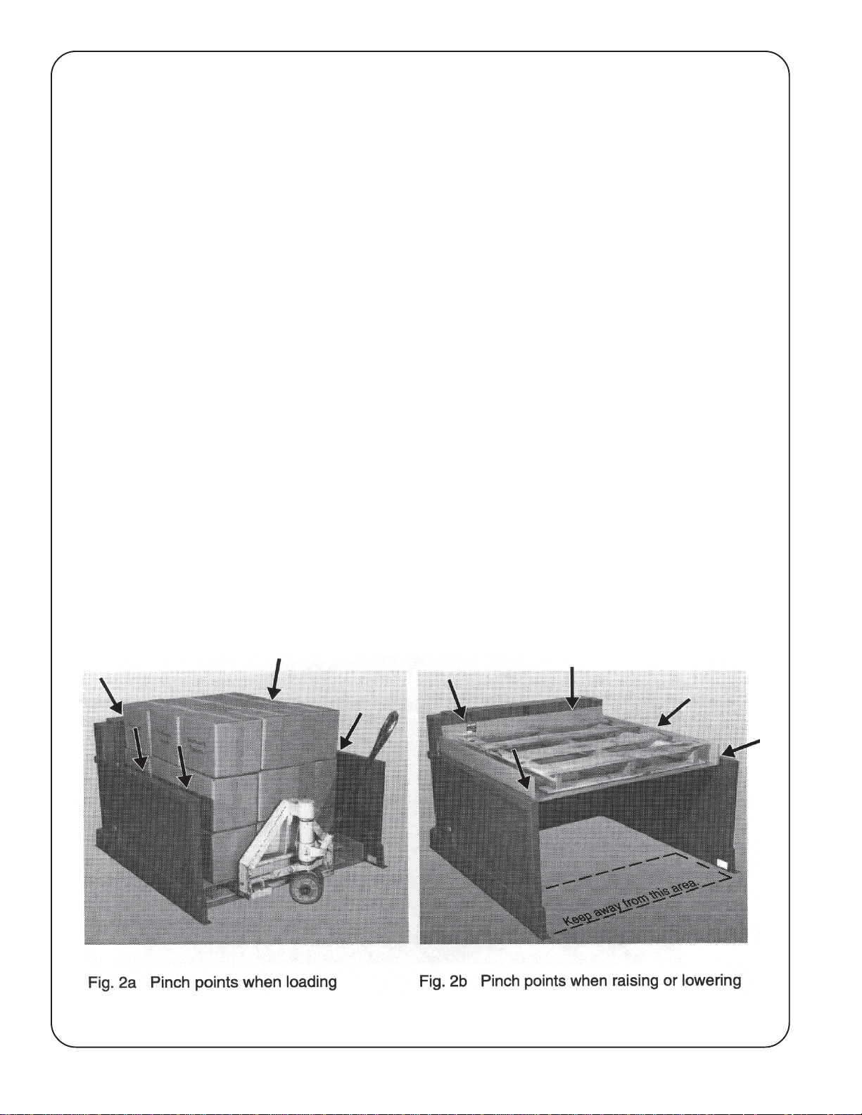
WARNING!
As the platform moves up and clown,
“pinch points” are created at the
places shown in Fig. 2. If you are
standing too close to the unit when
it is moving, your arm or leg may be
caught in the moving parts, and you
may be hurt. Stay away from the pinch
points when the unit is moving.
3. Test the unit with the rated load. If the unit
does not rise, and you hear a loud squealing
noise, the pressure relief valve is operating.
Contact Presto Lifts for instructions.
Testing
1. Clear the area around the unit. Remove any
loose wires, lumber, or other materials
which might get in the way of the unit as it
raises or lowers.
WARNING!
Don’t continue to use the unit if this
happens - the pump will overheat
very quickly , and may be permanently
damaged. Do not try to adjust the
relief valve. If you change the setting
6 PRESTO P4 LEVEL LOADER OWNER’S MANUAL
Page 7

on the relief valve, you may overwork
the unit. This can cause the unit to
fail suddenly, and you may be hurt.
WARNING!
As you operate this lift, follow these
rules:
4. Clean up any spilled hydraulic fluid. Spilled
hydraulic oil is slippery, and may present a
fire hazard. If you clean up any spilled fluid,
you will be able to tell right away if the unit
begins to leak.
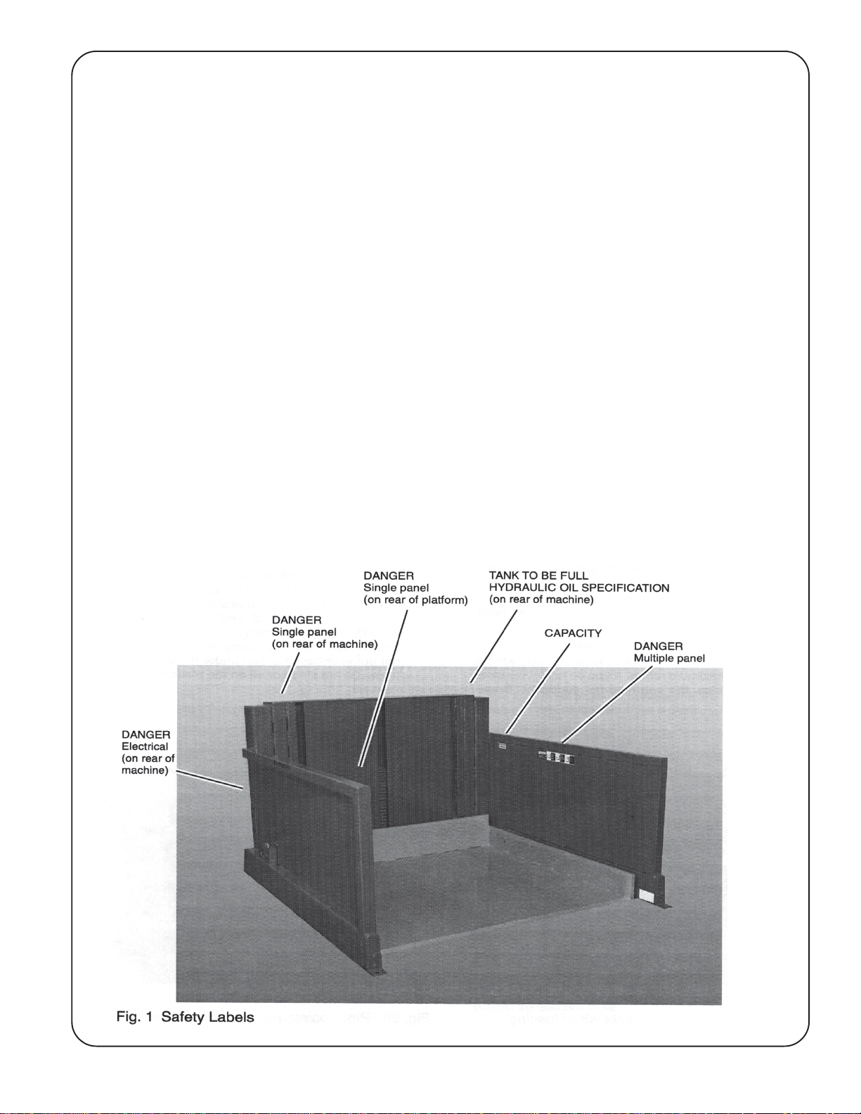
5. Figure 1 shows the safety labels on this
unit. Check to be sure all of the labels are in
place.
OPERATING INSTRUCTIONS
Safety Instructions
DANGER!
The unit uses a power supply of 115
Volts AC. This voltage can kill you.
DON’T WORK WITH THE
ELECTRICAL PARTS UNLESS YOU
ARE A QUALIFIED ELECTRICIAN!
• Do not put your hands or feet under
the lift platform.
• Do not work under the lift platform
without installing the safety pins.
(See Fig. 6 and the section on
“Maintenance.”)
• Do not stand, sit, or ride on the lift.
WARNING!
This unit includes a photo eye toe
guard. See Fig. 6. If something blocks
the light beam, the unit will stop
quickly. The control system will stop
the motor and close the down valve,
preventing the platform of the unit
from moving down. This is designed
to prevent the unit from lowering
PRESTO P4 LEVEL LOADER OWNER’S MANUAL 7
Page 8

onto the operator’s toes. If this safety
system is not working correctly, do
not operate the unit. Call a
maintenance worker right away .
Loading the Unit
1. Before operating the unit, please read and
understand all of this section.
2. Be sure that the load weighs no more than
the maximum rated for the unit. The
maximum rated load is listed on the data
plate. Remember that an empty pallet may
weigh 40 Ibs (18 kg) or more.
3. The load should always be balanced in the
side-to-side direction. Whenever possible,
place the load in the center of the pallet, as
shown in Fig. 3. If the load is off-center on
the pallet, place the heaviest part of the load
near the back of the platform - never near
the front!
suddenly. Someone may be hurt, or
the unit and load may be damaged.
• The unit is designed so it can lift
the rated load if
the load center is
placed over the center of the
platform. (The load center should be
24" or 61 cm from the rear of the
platform.) If the load is placed
“offcenter,” near the front of the
platform, the unit will not be able to
lift the rated load safely. It is also
important
that the load be centered
side-to-side. For these reasons, it is
very important to be sure the load is
centered in the platform area.
4. Sometimes the unit may be used to lift parts
which can roll. St ack the part s on the p allet
so they cannot roll. Be sure that all parts of
the load are secure, and will not move as
the unit is operated.
WARNING!
• Don’t try to lift a load that exceeds
the maximum rating. If you do not
follow these rules, the unit may fail
Raising the Platform
1. Before raising the platform, be sure all
workers are clear of the unit.
Fig. 4 Electrical diagram
8 PRESTO P4 LEVEL LOADER OWNER’S MANUAL
Page 9

WARNING!
As the platform moves up and down,
“pinch points” are created as shown
in Fig. 2. STAY AWAY FROM THESE
PINCH POINTS! Part of your body or
clothing may become caught, and
you may be hurt. Do not put your
hands or feet under the platform. Do
not stand or sit on the platform.
2. Before lifting, be sure the pallet is pushed
up against the back of the unit. Be sure the
fork lift or pallet truck is clear of the unit
before you begin lifting.
3. Plug in the electrical cord. Be sure the cord
cannot become caught in the moving parts
as the platform rises.
4. Operate the unit. Press and hold the Up
button to raise the platform, and Down to
lower it. If the unit does not operate right
away, unplug the power cord and call a
qualified maintenance worker .
WARNING!
If you hear a squealing noise from the
pump, the pressure relief valve is
operating. DON’T CONTINUE TO
USE THE UNIT! The pump will
overheat very quickly, and may be
permanently damaged. The relief
valve is included to protect the
machine operators - DO NOT
CHANGE THE SETTING ON THE
RELIEF V ALVE. If you do change the
setting, this may cause a hydraulic
part to fail. The platform may drop
suddenly . Someone may be hurt, and
the unit and load may be damaged.
The hydraulic parts in the unit are
designed to handle a certain amount
of pressure. The relief valve has
been included for the protection of
all of the workers who use the unit.
Lowering the Platform
1. Press the Down button to lower the platform.
PRESTO P4 LEVEL LOADER OWNER’S MANUAL 9
Page 10

2. Before lowering the platform, be sure all
workers are clear of the unit.
WARNING!
As the platform moves up and down,
“pinch points” are created as shown
in Fig. 2. STAY AWAY FROM THESE
PINCH POINTS! Part of your body or
clothing may become caught, and
you may be hurt.
3. There is a photoelectric toe guard near the
front of this unit. If anything blocks the
photoelectric beam, the unit will stop. This
is designed to prevent an operator from
lowering the platform onto his or her feet.
WARNING!
Stand back from the unit when
raising or lowering the platform.
Keep your feet away from the
platform when the unit is operating.
MAINTENANCE AND
TROUBLESHOOTING
All servicing should be done by qualified
personnel. Qualified personnel should be able
to read and understand wiring and hydraulic
diagrams. They should be able to troubleshoot
live electrical circuits safely and in accordance
with accepted practice. FOR SAFETY’S SAKE,
if in doubt, please contact your distributor or
Presto Lift’s Customer Service Department at
(800) 343-9322. Before servicing the unit,
please read and understand all of this section
and the section entitled “Operating Instructions.”
WARNINGS!
• As the unit moves up and down,
“pinch points” are formed as shown
in Fig. 2. KEEP HANDS, FEET AND
LOOSE CLOTHING AWAY FROM
THESE PINCH POINTS. If your hand
or arm or a part of your clothing is
caught, you may be hurt.
• Before performing any
maintenance on the unit, lower the
platform completely . Failure to do so
could result in severe personal
injury.
• You should not have to do any
maintenance work with the platform
raised. All normal maintenance can
be done with the platform lowered.
However, if you ever need to work
under the platform, you must be
careful to do this safely. Raise the
platform until you can insert the
safety pins on each side. The pins
are shown in Fig. 6. Finally, unplug
the power cord. DO NOT WORK
UNDER THE PLATFORM UNTIL YOU
HA VE INSERTED THE PINS. If you fail
to do this, the platform may drop
suddenly . You may be hurt.
• The relief valve has been included
for the protection of all of the
workers who use the unit. DON’T
CHANGE THE RELIEF SETTING! If
the relief valve does not open when
it should, the unit may fail. Someone
may be hurt, and the unit and load
may be damaged.
Hazards
There are several hazards you should be aware
of as you service the unit:
DANGER!
The unit uses a power supply of 115
Volts AC. This voltage can kill you.
DON’T WORK ON THE ELECTRICAL
PARTS UNLESS YOU ARE A
QUALIFIED ELECTRICIAN!
10 PRESTO P4 LEVEL LOADER OWNER’S MANUAL
• If the hydraulic fluid is released
under high pressure, it can cause
personal injury . Before you open any
part of the hydraulic system, BE
SURE TO RELEASE THE
HYDRAULIC PRESSURE. Y ou can do
this by lowering the platform all the
way down.
• The warning labels have been
included for the safety of the
Page 11

operator. If the labels are worn or
missing, or have been painted over,
REPLACE THEM before releasing
the lift for operation. Fig. 1 shows
the safety markings on this unit.
Routine Periodic Maintenance
Every month:
• Remove the plate on the rear of the unit and
check the mechanical parts. Inspect the leaftype chain which lifts the platform. Check for
signs of wear. If the machine is operated in a
very dusty environment, you may have to wipe
off the dust.
Sometimes the fittings can be worked loose by
the vibrations from the power unit.
WARNING!
If a hydraulic fitting becomes loose,
or if a hydraulic hose breaks, the
hydraulic fluid may escape from the
system under pressure. If the
platform is raised when this happens,
it can drop quickly. Someone may be
hurt, or the unit or load may be
damaged. To avoid this problem,
inspect all of the hydraulic hoses and
fittings regularly, and replace them
if they are worn or damaged.
• Check the bolts which anchor the ends of
the chain. The chain should be tight, and each
bolt should be locked in place.
• Check the level and appearance of the
hydraulic fluid. In order to check the level, lower
the unit completely and unplug the power cord.
Remove the rear cover on the unit. Remove the
red plastic vent plug on top of the hydraulic tank,
and use a dipstick to check the oil level. When
the platform is fully lowered, the oil should be
about 1/2’’ to 3/4’’ inch below the top of the tank.
Add oil if necessary. Change the oil if it has
darkened, or feels gritty or sticky .
CAUTION!
It is important to use hydraulic fluid
with the correct grade and
properties. See the hydraulic oil
specification in Fig. 10 of this manual.
Every six months or 500 hours of operation,
whichever comes first:
• Lubricate the lifting chain lightly with spray
lube or SAE 30 mineral oil.
• Lubricate the bushing inside the sheave or
pulley which supports the upper part of the
chain.
• Apply a light coat of grease to the vertical
guides for the rollers on the rear of the unit.
• The clear plastic vent line and the cylinder
rod should be free of hydraulic fluid. If you find
much fluid in either place, the cylinder seals
may be leaking. (It is also possible the tank
may be over-filled.) If the worn parts must be
replaced, see the section on “Repacking the
Cylinder.”
• Lower the platform and disassemble the
down valve as shown in Fig. 8. Blow the valve
plunger clean with compressed air.
Reassemble the valve and reinstall it.
• Drain and discard the hydraulic fluid. The
suction filter is in the tank, at the point where
the suction line runs out to the pump. Unscrew
the hydraulic line, then remove the filter. Blow
the filter clean with compressed air. Reinstall
the filter in the tank and reassemble the
hydraulic line.
• Refill the tank with new hydraulic fluid.
CAUTION!
If you continue to use fluid after it
has “worn out,” the moving parts in
the system will wear more quickly .
• Be sure all of the warning labels are in position
and legible. See Fig. 1. THE WARNING
LABELS ARE INTENDED TO PROTECT
YOUR WORKERS. If the labels are missing,
or if they have been painted over , replace them.
• Check all of the hydraulic fittings and hoses,
and tighten the connections if necessary.
PRESTO P4 LEVEL LOADER OWNER’S MANUAL 11
Page 12

Troubleshooting Check List
All servicing should be done by qualified
personnel. Qualified personnel should be able
to read and understand wiring and hydraulic
diagrams. They should be able to troubleshoot
live electrical circuits safely and in accordance
with accepted practice. FOR SAFETY’S SAKE,
if in doubt, please contact your distributor or
Presto Lifts at (800) 343-9322.
Before servicing the unit, read and understand
this entire section and the section entitled
“Operating Instructions.”
WARNING!
Before performing any maintenance
on this unit, lower the platform
completely.
If the platform will not raise:
CAUTION!
If the platform will not raise, do not
continue to hold the Up button for
more than 2 or 3 seconds. You may
damage the pump.
1. The sensor and reflector are mounted at
the front of the unit, near the floor level. There
may be something blocking the beam of the
photo eye toe guard. The reflector may need
to be cleaned or replaced.
2. The load may be too heavy . Check the actual
weight of the load. The rated capacity of the
unit is shown on the name plate.
WARNING!
DON’T CHANGE THE SETTING OF
THE RELIEF V AL VE. If you do change
the setting, this may cause a
hydraulic part to fail. The platform
may drop suddenly . Someone may be
hurt, and the unit and load may be
damaged. The hydraulic parts in the
lift are designed to handle a certain
amount of pressure. The relief valve
is set to relieve this pressure before
it becomes too great. The relief
12 PRESTO P4 LEVEL LOADER OWNER’S MANUAL
Page 13

Outer spring
R
Inner spring
elief valve poppet
Coupling – pump
to motor
Gasket
Relief valve cap
Retainer ring
Relief valve
adjusting screw
Down valve plunger
Down valve strainer
Nut
Down valve solenoid
Check valve cap
O-ring
Check valve spring
Check valve ball
Fig. 8 Pump
PRESTO P4 LEVEL LOADER OWNER’S MANUAL 13
Page 14

valve has been included for the
protection of all of the workers who
use the unit.
3. If the motor is not running, check the
electrical plug, the circuit breaker or fuse,
and the wiring to the motor .
4. The hydraulic oil level may be low. In order to
check the level, lower the unit completely
and unplug the power cord. Remove the rear
cover on the unit. When the platform is
lowered as far as possible, the oil should
be about 1/2’’ to 3/4’’ inch below the top of
the tank. Remove the red plastic plug on
top of the tank. Use a dipstick to check the
oil level.
5. The motor voltage may be too low. Check
the voltage at the starter when the motor is
under load. The supply voltage should be
within ±10% of the rating.
6. The tank vent may be plugged. Before
operating the unit, you must remove the solid
plug from the top of the tank and insert the
red plastic vented plug. The vent line must
be clear.
7. The suction filter may be clogged. Clean the
suction filter as described in the section on
“Periodic Maintenance.”
8. A vacuum leak may be allowing air into the
suction line, causing cavitation (loss of
suction) in the pump. Check all fittings in
the suction line, and tighten or replace them
if necessary.
CAUTION!
If cavitation is allowed to continue,
the pump may be damaged, and may
have to be replaced.
9. For the platform to raise, the down valve
must be de-energized and closed
completely. Check for a problem with the
wiring to the down valve. Check the solenoid
in the valve with a voltmeter. The valve must
be clean and free to operate. To check this,
remove the solenoid and then the valve. Look
for dirt or metal chips which could block the
valve action. Clean the valve plunger with
kerosene, then blow it clean with
compressed air. The expansion nut which
holds the solenoid should be finger tight
only).
10. If the pump has been changed, the coupling
may not have been installed between the
motor and pump. See the pump assembly
in Fig. 8.
If the platform elevates, but fails to hold a load:
1. The check valve may be leaking. Dirt on the
valve seat can prevent the valve from
closing fully . The check valve is mounted in
the base of the pump housing, as shown in
Fig. 8. Remove the check valve cap and
inspect the valve for dirt or metal chips
which may be preventing it from closing. Y ou
may be able to restore the seal by lightly
rapping the ball into the seat using a 1/4"
diameter rod and a small hammer.
2. The down valve may be energized. While
the unit is holding a load, the down valve
should be de-energized and fully closed.
Check the solenoid in the valve with a
voltmeter . The valve must be clean and free
to operate. To check this, remove the
solenoid and then the valve. Look for dirt or
metal chips which could block the valve
action. Clean the valve plunger with
kerosene, then blow it clean with
compressed air. The expansion nut which
holds the solenoid should be finger tight only!
3. The cylinder may be leaking. Look for oil on
the cylinder rod and in the vent line. (This
may also occur if the oil tank has been overfilled.) If you find much oil in either place,
and the tank is not over-filled, the cylinder
must be repacked. See the section in this
manual on “Repacking the Cylinder .”
If the platform fails to lower:
1. The sensor and reflector for the photo eye
toe guard are mounted at the front of the
unit, near the floor level. There may be
something blocking the beam of the photo
14 PRESTO P4 LEVEL LOADER OWNER’S MANUAL
Page 15

eye. The reflector may need to be cleaned
or replaced.
2. The down valve may be de-energized. While
the platform is lowering, the down valve
should be energized and fully open. Check
the solenoid in the valve with a voltmeter.
The valve must be clean and free to operate.
Remove the solenoid, then the down valve.
Look for dirt or metal chips which could block
the valve action. Clean the valve plunger
with kerosene, then blow it clean with
compressed air. Before reassembly,
depress the plunger manually several times
to be sure it moves freely . The expansion
nut which holds the solenoid should be
finger tight only! If these steps do not solve
the problem, please call the Presto Lifts
Customer Service Department at (800) 343-9322.
Repacking the Cylinder
The lift in the P4 Level Loader unit may use
several different types of cylinders. To order a
repacking kit and receive repacking instructions,
please call the Presto Lifts Parts Department
at (800) 343-9322. When ordering, specify the
model number and serial number of the unit.
Adjusting the Chain Tension
It is very important that the lifting chain be
tensioned correctly . As the chain is used, it will
tend to stretch a bit. Over time, this can cause
it to loosen. The adjustment mechanism is
located on the rear of the unit. See Fig. 7.
1. Lower the platform completely and unplug
the unit. Remove the plate on the rear of the
unit.
2. Loosen the two locking bolts.
3. Find the two tensioning bolts. Loosen the
locknuts so you can turn these bolts.
4. Turn the tensioning bolts in or out to change
the chain tension. The chain tension should
be as tight as possible without lifting the
platform off of the floor. The setting should
be the same on each side of the
mechanism.
5. When the tension is correct, tighten the lock
nuts.
6. Tighten the two locking bolt s.
PRESTO P4 LEVEL LOADER OWNER’S MANUAL 15
Page 16

Ordering Replacement Parts
Presto Lifts has carefully chosen the components in your unit to be the best available for the purpose. Replacement
parts should be identical to the original equipment. Presto Lifts will not be responsible for equipment failures
resulting from the use of incorrect replacement parts or from unauthorized modifications to the unit.
Presto Lifts can supply all replacement parts for your lift. With your order , please include the model number and
the serial number of the unit. You can find these numbers on the name plate. This plate is located on the lower
corner of the right side panel.
To order replacement parts, please call the Presto Parts Department. Parts are shipped subject to the following
terms:
• FOB factory
• Returns only with the approval of our parts department.
• Credit cards preferred (except parts covered by warranty).
• Freight collect for truck (except parts covered by warranty).
• Freight – prepaid and invoice for small parcel shipments (except parts covered by warranty).
Parts replaced under warranty are on a “charge-credit” basis. We will invoice you when we ship the replacement
part, then credit you when you return the worn or damaged part.
Presto Parts Department
21 Park Street
Attleboro, MA 02703
T elephone: 800-343-9322
F AX: 888-788-6496
Email: service@PrestoLifts.com
www.PrestoLifts.com
Table 10 – Hydraulic Oil Specifications
If the lift will be used at normal ambient temperatures, Presto Lifts supplies the unit
with Citgo AW 32 oil. This may be replaced by any other good quality oil with 150 SSU
at 100° F and rust and oxidation inhibitors and anti-wear properties.
If the lift will be used at ambient temperatures below 0°F, use aircraft hydraulic oil.
Use Type 15 aircraft hydraulic oil.
The following are equivalent to CITGO AW32:
TYPE MANUFACTURER
DTE 24 ..........................EXXON/MOBIL
NUTO H32 .................... EXXON/MOBIL
AMOCO AW32.............. CHEVRON (AMOCO CO.)
CAUTION!
It is very important to keep the hydraulic oil free of dirt, dust, metal
chips, water, and other contamination. Most of the problems with
hydraulic systems are caused by contamination in the oil.
16 PRESTO P4 LEVEL LOADER OWNER’S MANUAL
Page 17

RESTOCKING POLICY
Presto Lift, Inc.’s goal is for you to be satisfied with your order. Merchandise may be returned,
but returns will be subject to a restocking fee to cover the costs Presto Lift, Inc. incurs which
include but are not limited to handling, storage of the units, etc. Presto Lift, Inc. will issue refurbishing costs where end-user wear is apparent. We would prefer to not charge for these costs
but find it necessary any apologize for any inconvenience. Please review the RETURN MATERIALS AUTHORIZATION (RMA) PROCEDURES.
LIFTS
Lifts may be returned with a restocking fee according to the following schedule:
1. Standard unit or standard unit with stock options:
Three or less 20 %
With re-order 15%
Four or more of the same model Consult Customer Svc.
With re-order Consult Customer Svc.
2. Custom engineered/modified lifts: No Returns
PARTS
Standard parts may be returned with a 20% restocking fee. Modified or custom-engineered parts
are not returnable. Unfortunately, due to potentially concealed damage, all sales of electrical
assemblies are final.
QUALITY ISSUES
Should you feel there is a quality problem, please contact the seller to ask questions and gather
information on how to rectify the issue. Presto Lift Inc. reserves the right to determine potential
credits, as a result of factory defects, based on its inspection of the merchandise.
GENERAL
All products shipped from our factory have passed Quality Assurance inspection and testing.
The carrier of choice has signed for, and accepted the product in new working condition. The
customer should inspect to ensure it is not received damaged, has no concealed damage or is not
incomplete. Parts orders are determined to be complete based upon Presto Lift, Inc. inspection
sheets and carrier shipping weights.
PRESTO P4 LEVEL LOADER OWNER’S MANUAL 17
Page 18

RETURN MA TERIALS AUTHORIZA TION
(RMA) PROCEDURES
Although Presto Lift, Inc. is not legally obligated to issue a credit for any merchandise, the
RETURN MATERIALS AUTHORIZATION (RMA) PROCEDURE is provided as a cour-
tesy to our customers in the event they do not receive what they wanted.
If a customer wishes to return a Presto Lift, Inc. product, the first step in the process is to
request an RMA number from Presto Lift, Inc.’s Customer Service Department. This request
must be made on or before the thirtieth (30th) calendar day following the date of Presto Lift,
Inc.’ s invoice for the merchandise being returned.
The RMA number must appear on the outside of any packaging material for a return to be
accepted and processed by Presto Lift, Inc. Customers shipping returns back to Presto Lift,
Inc. from the Continental US, Canada and Mexico have thirty (30) days from the effective
date of the RMA to have the merchandise arrive freight prepaid at Presto Lift, Inc. Returns
from locations other than the Continental US, Canada and Mexico must be shipped within the
thirty (30) day period to arrive Free On Board (FOB) at Presto Lift Inc as soon as practical. If
a customer believes Presto Lift, Inc.’s merchandise is defective, freight will be reimbursed to
the original “Bill To” on the invoice if Presto Lift Inc. finds that the merchandise is defective.
Please remember that merchandise with RMA’s coming back to Presto Lift Inc. from the
Continental US, Canada and Mexico will not be accepted by Presto Lift Inc. if the returned
goods do not arrive freight prepaid at Presto Lift Inc. within the thirty (30) day effective period.
All credits issued are less restocking fees as applicable, plus any assessed outbound/inbound
in-transit damages.
Return addresses: please refer to your RMA for the address to which your product should be
returned.
Presto Lift Inc.
715 Highway 77
Manila, Arkansas 72442
T elephone: 800-343-9322
Fax: 888-788-6496
18 PRESTO P4 LEVEL LOADER OWNER’S MANUAL
Page 19

PRESTO P4 LEVEL LOADER OWNER’S MANUAL 19
Page 20

Presto Lifts Limited Warranty Policy
Presto Lifts warrants all of its products against defects in the welded structural frame and, if
applicable, scissor legs from faulty material and workmanship for a period of five (5) years from
the date of invoice.
A lifetime limited warranty is provided for the Airstroke Actuator
defect due to faulty material or workmanship.
All batteries are covered under a separate limited warranty from the battery manufacturer for a
period of one year from the date of invoice.
All other components have a limited warranty against defects in faulty material and workmanship
for a two (2) year period from the date of invoice and 30 day limited warranty on labor. Please
note that prior authorization from Presto Lifts is required on all warranty work.
There are no implied warranties of any kind, more specifically, there are no warranties of merchantability or fitness for any particular purpose. Presto Lifts' sole warranty shall be as set forth in
this limited warranty .
Presto Lifts will elect to repair or replace a defective component without charge, if any components should become defective within the limited warranty period. Proof of purchase is required
for warranty. The charge for shipping the defective component is the responsibility of the buyer
and must be accompanied with an RMA number. The shipping charge to return the component to
the buyer is the responsibility of Presto Lifts, Inc.
TM in all pneumatic lifts against any
This limited warranty does not cover labor expense for removal or reinstallation of components
after thirty days. This limited warranty shall not cover, among other things: damages resulting from
foreign matter or water, failure to provide reasonable and necessary maintenance, and if applicable, use of product while charger is plugged into an AC outlet, or failure to follow operating
instructions. The limited warranty is not valid for damage resulting from negligence, accident,
unreasonable use, abuse or misuse, exceeding data plate capacities or altering the product without
Presto Lifts authorization.
Presto Lifts expressly disclaims and excludes any liability for consequential, incidental, indirect or
punitive damages or financial loss to people or property resulting from any breach of warranty or
the operation or failure of this product.
Presto Lifts makes no representation that this product complies with local, state, or federal safety/
product standards codes. Should this product fail to comply in any way with those codes, it shall
not be considered a defect of materials or workmanship. Presto Lifts shall not be held liable for
any damages resulting from noncompliance. It is the dealer's responsibility to exercise this limited
warranty . This limited warranty is provided to the original purchaser (defined as the original end
user) and is nontransferable. This constitutes the complete and final agreement involving Presto
Lifts and limited warranty obligations for products.
20 PRESTO P4 LEVEL LOADER OWNER’S MANUAL
 Loading...