

Page 1

PRESTIGIO SIGNORE 152
TECHNICAL SERVICE
MANUAL
Page 2

Service Guide
PART NO.:
49.42W01.Z01
PRINTED IN TAIWAN
Page 3

Revision History
Please refer to the table below for the updates made on OpenBook 1846 service guide.
Date Chapter Updates
II
Page 4

Copyright
Copyright © 2002 by Wistron Corporation. All rights reserved. No part of this publication may be reproduced,
transmitted, transcribed, stored in a retrieval system, or translated into any language or computer language, in
any form or by any means, electronic, mechanical, magnetic, optical, chemical, manual or otherwise, without
the prior written permission of Wistron Corporation.
Disclaimer
The information in this guide is subject to change without notice.
Wistron Corporation makes no representations or warranties, either expressed or implied, with respect to the
contents hereof and specifically disclaims any warranties of merchantability or fitness for any particular
purpose. Any Wistron Corporation software described in this manual is sold or licensed "as is". Should the
programs prove defective following their purchase, the buyer (and not Wistron Corporation, its distributor, or
its dealer) assumes the entire cost of all necessary servicing, repair, and any incidental or consequential
damages resulting from any defect in the software.
Intel is a registered trademark of Intel Corporation.
Pentium and Pentium II/III are trademarks of Intel Corporation.
Other brand and product names are trademarks and/or registered trademarks of their respective holders.
III
Page 5

Conventions
The following conventions are used in this manual:
Screen messages Denotes actual messages that appear
on screen.
NOTE Gives bits and pieces of additional
information related to the current
topic.
WARNING Alerts you to any damage that might
result from doing or not doing specific
actions.
CAUTION Gives precautionary measures to
avoid possible hardware or software
problems.
IMPORTANT Reminds you to do specific actions
relevant to the accomplishment of
procedures.
IV
Page 6

Preface
Before using this information and the product it supports, please read the following general information.
1. This Service Guide provides you with all technical information relating to the BASIC CONFIGURATION
decided for our "global" product offering. To better fit local market requirements and enhance product
competitiveness, your regional office MAY have decided to extend the functionality of a machine (e.g.
add-on card, modem, or extra memory capability). These LOCALIZED FEATURES will NOT be covered
in this generic service guide. In such cases, please contact your regional offices or the responsible
personnel/channel to provide you with further technical details.
2. Please note WHEN ORDERING FRU PARTS, that you should check the most up-to-date information
available on your regional web or channel. If, for whatever reason, a part number change is made, it will
not be noted in the printed Service Guide. For AUTHORIZED SERVICE PROVIDERS, your office may
have a DIFFERENT part number code to those given in the FRU list of this printed Service Guide. You
MUST use the list provided by your regional office to order FRU parts for repair and service of customer
machines.
V
Page 7

Chapter 1 System Specifications 1
Features . . . . . . . . . . . . . . . . . . . . . . . . . . . . . . . . . . . . . . . . . . . . . . . . . . . . . . . .1
System Block Diagram . . . . . . . . . . . . . . . . . . . . . . . . . . . . . . . . . . . . . . . . . . . . .2
Board Layout . . . . . . . . . . . . . . . . . . . . . . . . . . . . . . . . . . . . . . . . . . . . . . . . . . . . 3
Top View . . . . . . . . . . . . . . . . . . . . . . . . . . . . . . . . . . . . . . . . . . . . . . . . . . . .3
Bottom View . . . . . . . . . . . . . . . . . . . . . . . . . . . . . . . . . . . . . . . . . . . . . . . . .4
Outlook View . . . . . . . . . . . . . . . . . . . . . . . . . . . . . . . . . . . . . . . . . . . . . . . . . . . . .5
Top View . . . . . . . . . . . . . . . . . . . . . . . . . . . . . . . . . . . . . . . . . . . . . . . . . . . .5
Front View . . . . . . . . . . . . . . . . . . . . . . . . . . . . . . . . . . . . . . . . . . . . . . . . . . .6
Left Panel . . . . . . . . . . . . . . . . . . . . . . . . . . . . . . . . . . . . . . . . . . . . . . . . . . .6
Right Panel . . . . . . . . . . . . . . . . . . . . . . . . . . . . . . . . . . . . . . . . . . . . . . . . . .7
Rear Panel . . . . . . . . . . . . . . . . . . . . . . . . . . . . . . . . . . . . . . . . . . . . . . . . . .8
Bottom Panel . . . . . . . . . . . . . . . . . . . . . . . . . . . . . . . . . . . . . . . . . . . . . . . .9
Indicators . . . . . . . . . . . . . . . . . . . . . . . . . . . . . . . . . . . . . . . . . . . . . . . . . . . . . .10
Lock Keys . . . . . . . . . . . . . . . . . . . . . . . . . . . . . . . . . . . . . . . . . . . . . . . . . . . . . .11
Embedded Numeric Keypad . . . . . . . . . . . . . . . . . . . . . . . . . . . . . . . . . . . . . . . . 12
Windows Keys . . . . . . . . . . . . . . . . . . . . . . . . . . . . . . . . . . . . . . . . . . . . . . . . . .13
Hot Keys . . . . . . . . . . . . . . . . . . . . . . . . . . . . . . . . . . . . . . . . . . . . . . . . . . . . . . . 14
Launch Keys . . . . . . . . . . . . . . . . . . . . . . . . . . . . . . . . . . . . . . . . . . . . . . . . . . . .15
Hardware Specifications and Configurations . . . . . . . . . . . . . . . . . . . . . . . . . . .16
Chapter 2 System Utilities 27
BIOS Setup Utility . . . . . . . . . . . . . . . . . . . . . . . . . . . . . . . . . . . . . . . . . . . . . . . .27
Navigating the BIOS Utility . . . . . . . . . . . . . . . . . . . . . . . . . . . . . . . . . . . . . . . . .27
Multi-Boot Menu . . . . . . . . . . . . . . . . . . . . . . . . . . . . . . . . . . . . . . . . . . . . . . . . .28
System Information . . . . . . . . . . . . . . . . . . . . . . . . . . . . . . . . . . . . . . . . . . .28
Basic System Settings . . . . . . . . . . . . . . . . . . . . . . . . . . . . . . . . . . . . . . . .29
Startup Configuration . . . . . . . . . . . . . . . . . . . . . . . . . . . . . . . . . . . . . . . . .31
Primary Master . . . . . . . . . . . . . . . . . . . . . . . . . . . . . . . . . . . . . . . . . . . . . .32
Secondary Master . . . . . . . . . . . . . . . . . . . . . . . . . . . . . . . . . . . . . . . . . . . .33
OnBoard Device Configuration . . . . . . . . . . . . . . . . . . . . . . . . . . . . . . . . . .34
System Security . . . . . . . . . . . . . . . . . . . . . . . . . . . . . . . . . . . . . . . . . . . . . 35
Boot Options . . . . . . . . . . . . . . . . . . . . . . . . . . . . . . . . . . . . . . . . . . . . . . . .39
Exit Setup . . . . . . . . . . . . . . . . . . . . . . . . . . . . . . . . . . . . . . . . . . . . . . . . . .40
BIOS Flash Utility . . . . . . . . . . . . . . . . . . . . . . . . . . . . . . . . . . . . . . . . . . . . . . . .41
System Utility Diskette . . . . . . . . . . . . . . . . . . . . . . . . . . . . . . . . . . . . . . . . . . . . 42
System Diagnostic Diskette . . . . . . . . . . . . . . . . . . . . . . . . . . . . . . . . . . . . . . . .43
Running PQA Diagnostics Program . . . . . . . . . . . . . . . . . . . . . . . . . . . . . .44
Chapter 3 Machine Disassembly and Replacement 47
General Information . . . . . . . . . . . . . . . . . . . . . . . . . . . . . . . . . . . . . . . . . . . . . .48
Before You Begin . . . . . . . . . . . . . . . . . . . . . . . . . . . . . . . . . . . . . . . . . . . .48
Disassembly Procedure Flowchart . . . . . . . . . . . . . . . . . . . . . . . . . . . . . . . . . . .49
Removing the Battery Pack . . . . . . . . . . . . . . . . . . . . . . . . . . . . . . . . . . . . . . . .51
Removing the Extended Memory . . . . . . . . . . . . . . . . . . . . . . . . . . . . . . . . . . . .52
Removing the Modem Board . . . . . . . . . . . . . . . . . . . . . . . . . . . . . . . . . . . . . . .53
Removing the CD-RW Drive Module . . . . . . . . . . . . . . . . . . . . . . . . . . . . . . . . .54
Disassembling the CD-RW Drive Module . . . . . . . . . . . . . . . . . . . . . . . . . .54
Removing the Hard Disk Drive Module . . . . . . . . . . . . . . . . . . . . . . . . . . . . . . . .55
Disassembling the Hard Disk Drive Module . . . . . . . . . . . . . . . . . . . . . . . .55
Disassembling the LCD . . . . . . . . . . . . . . . . . . . . . . . . . . . . . . . . . . . . . . . . . . .56
Removing the Middle Cover . . . . . . . . . . . . . . . . . . . . . . . . . . . . . . . . . . . .56
Removing the Keyboard . . . . . . . . . . . . . . . . . . . . . . . . . . . . . . . . . . . . . . .56
Removing the LCD Module . . . . . . . . . . . . . . . . . . . . . . . . . . . . . . . . . . . . .57
VI
Page 8

Table of Contents
Removing LCD Bezel . . . . . . . . . . . . . . . . . . . . . . . . . . . . . . . . . . . . . . . . .58
Removing the Inverter/LED Board . . . . . . . . . . . . . . . . . . . . . . . . . . . . . . .59
Removing the LCD . . . . . . . . . . . . . . . . . . . . . . . . . . . . . . . . . . . . . . . . . . .59
Removing the Coaxial Cable . . . . . . . . . . . . . . . . . . . . . . . . . . . . . . . . . . . 60
Disassembling the Upper Case . . . . . . . . . . . . . . . . . . . . . . . . . . . . . . . . . . . . .61
Removing the Touch Pad . . . . . . . . . . . . . . . . . . . . . . . . . . . . . . . . . . . . .62
Disassembling the Lower Case . . . . . . . . . . . . . . . . . . . . . . . . . . . . . . . . . . . . .63
Removing the Keyboard Support Bracket . . . . . . . . . . . . . . . . . . . . . . . . . . 63
Removing the DC Charger Plate . . . . . . . . . . . . . . . . . . . . . . . . . . . . . . . . 63
Removing the RTC Battery . . . . . . . . . . . . . . . . . . . . . . . . . . . . . . . . . . . . . 63
Removing the DC-DC Board . . . . . . . . . . . . . . . . . . . . . . . . . . . . . . . . . . . . 64
Removing the CPU Fan Sink . . . . . . . . . . . . . . . . . . . . . . . . . . . . . . . . . . .64
Removing the CPU (Part I) . . . . . . . . . . . . . . . . . . . . . . . . . . . . . . . . . . . . .65
Installing the CPU (Part I) . . . . . . . . . . . . . . . . . . . . . . . . . . . . . . . . . . . . . .65
Removing the CPU (Part II) . . . . . . . . . . . . . . . . . . . . . . . . . . . . . . . . . . . . 65
Installing the CPU (Part II) . . . . . . . . . . . . . . . . . . . . . . . . . . . . . . . . . . . . .66
Removing the Thermal Plate . . . . . . . . . . . . . . . . . . . . . . . . . . . . . . . . . . . 66
Removing the Floppy Disk Drive Module . . . . . . . . . . . . . . . . . . . . . . . . . .67
Removing the Speakers . . . . . . . . . . . . . . . . . . . . . . . . . . . . . . . . . . . . . . .68
Removing the Main Board . . . . . . . . . . . . . . . . . . . . . . . . . . . . . . . . . . . . .69
Removing the PCMCIA . . . . . . . . . . . . . . . . . . . . . . . . . . . . . . . . . . . . . . . . 70
Removing the I/O Port bracket . . . . . . . . . . . . . . . . . . . . . . . . . . . . . . . . . .70
Chapter 4 Troubleshooting 73
System Check Procedures . . . . . . . . . . . . . . . . . . . . . . . . . . . . . . . . . . . . . . . . .74
External Diskette Drive Check . . . . . . . . . . . . . . . . . . . . . . . . . . . . . . . . . .74
External CD/DVD-ROM Drive Check . . . . . . . . . . . . . . . . . . . . . . . . . . . . .74
Keyboard or Auxiliary Input Device Check . . . . . . . . . . . . . . . . . . . . . . . . .74
Memory Check . . . . . . . . . . . . . . . . . . . . . . . . . . . . . . . . . . . . . . . . . . . . . .75
Power System Check . . . . . . . . . . . . . . . . . . . . . . . . . . . . . . . . . . . . . . . . .75
Touchpad Check . . . . . . . . . . . . . . . . . . . . . . . . . . . . . . . . . . . . . . . . . . . . .76
Phoenix BIOS Error Code Messages . . . . . . . . . . . . . . . . . . . . . . . . . . . . . . . . .77
Power-On Self-Test (POST) Error Message . . . . . . . . . . . . . . . . . . . . . . . . . . .80
Index of Error Messages . . . . . . . . . . . . . . . . . . . . . . . . . . . . . . . . . . . . . . .80
Index of Symptom-to-FRU Error Message . . . . . . . . . . . . . . . . . . . . . . . . . . . . .82
Intermittent Problems . . . . . . . . . . . . . . . . . . . . . . . . . . . . . . . . . . . . . . . . .86
Undetermined Problems . . . . . . . . . . . . . . . . . . . . . . . . . . . . . . . . . . . . . . .86
Index of PQA Diagnostic Error Code, Message . . . . . . . . . . . . . . . . . . . . . 87
Chapter 5 Jumper and Connector Locations 89
Top View . . . . . . . . . . . . . . . . . . . . . . . . . . . . . . . . . . . . . . . . . . . . . . . . . . . . . . .89
Dip Switch Setting . . . . . . . . . . . . . . . . . . . . . . . . . . . . . . . . . . . . . . . . . . . .90
Bottom View . . . . . . . . . . . . . . . . . . . . . . . . . . . . . . . . . . . . . . . . . . . . . . . . . . . .91
Chapter 6 FRU (Field Replaceable Unit) List 93
Exploded Diagram . . . . . . . . . . . . . . . . . . . . . . . . . . . . . . . . . . . . . . . . . . . . . . . 94
Appendix A Model Definition and Configuration 105
Appendix B Test Compatible Components 107
Microsoft Windows XP Environment Test . . . . . . . . . . . . . . . . . . . . . . . . . . . . .108
Appendix C Online Support Information 111
Index 113
VII
Page 9

TECHNICAL SERVICE MANUAL Prestigio Signore 152
Chapter 1
System Specifications
Features
This computer was designed with the user in mind. Here are just a few of its many features:
Performance
Intel® Pentinum IV Desktop Northwood up to 2.4GHz processor with 256KB L2 cache/ Desktop
T
Celeron 1.7 GHz (and higher) with 128KB L2 cache.
128/256/512MB 144-pin SDRAM memory sockets (DDR 333/ 266)
T
Large LCD display with high performance 2D/ 3D graphics
T
High-capacity, Enhanced-IDE hard disk and CD-R/ RW/ DVD ROM.
T
Smart Lithium-Ion or Smart Nickel Metal-Hydride battery pack
T
Power management system
T
Dual display capability
T
Simultaneous LCD and CRT display
T
Multimedia
Built-in AC97 audio subsystem.
T
Built-in dual stereo speakers
T
Internal removable optical drive (CD-ROM, CD-RW or DVD/CD-RW combo)
T
Support S/PDIF digital audio output.
T
Connectivity
High-speed fax/data modem port
T
Onboard PCI 10/100 Mbps LAN support
T
PS/2 keyboard/keypad interface,
T
USB (Universal Serial Bus) ports
T
IEEE 1394 port
T
Human-centric design and ergonomics
All-in-one design.
T
Smooth and stylish design.
T
Full-sized keyboard
T
Wide and curved palm rest
T
Ergonomically-centered touchpad pointing device with Internet scroll key
T
Launch keys
T
Expansion
Upgradeable memory and hard disk
T
Swappable Media bay modules
T
1
Page 10
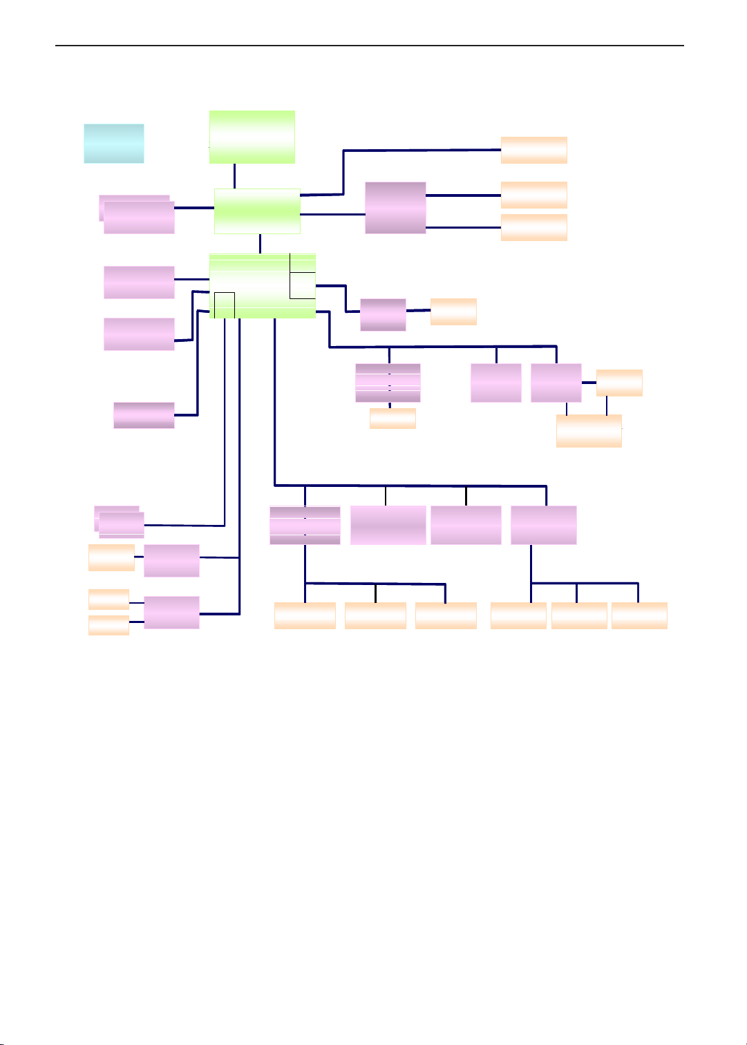
System Block Diagram
CLK GEN
CLK GEN
ICS:I CS952004AG
ICS:I CS952004AG
DDRBUF:I CS93722
DDRBUF:I CS93722
DDR* 2
DDR* 2DDR* 2
Pri mary EI DE
Pri mary EI DE
HDD ATA 100
HDD ATA 100
Seconda ry EIDE
Seconda ry EIDE
CD-ROM/COMBO
CD-ROM/COMBO
Ther mal
Ther mal
G768D
G768D
De s kt op - CP U
De s kt op - CP U
Northwood 0.13u 2.0G - 2.4G
Northwood 0.13u 2.0G - 2.4G
2.5V
2.5V
266MHz
266MHz
USB 2 .0
USB 2 .0
962 only
962 only
GTL+
GTL+
100/133MHz
100/133MHz
SiS650
SiS650
SiSM962
SiSM962
TECHNICAL SERVICE MANUALPrestigio Signore 152
CRT
CRT
VGA R/G/ B
VGA R/G/ B
SIS
VB 3.3V/1.8V
VB 3.3V/1.8V
MuT IO L 6 6 MHz
MuT IO L 6 6 MHz
16bits/533MBs
16bits/533MBs
LAN MAC
LAN MAC
1394
1394
1394 MAC
1394 MAC
962 only
962 only
W/R
W/R
TC
TC
PCI Bus
PCI Bus
33MHz
33MHz
LPC Bus
LPC Bus
33MHz
33MHz
SIS
302LV
302LV
PHY
PHY
TI -TS B41 AB1
TI -TS B41 AB1
/TSB41AB2
/TSB41AB2
LAN
LAN
Realtek 8100(B)
Realtek 8100(B)
RJ 4 5
RJ 4 5
Dual LVDS
Dual LVDS
1394
1394
conn.
conn.
Mi ni PCI
Mi ni PCI
802.11B
802.11B
14.1”/15”
14.1”/15”
TV
TV
LCD
LCD
Car dBus
Car dBus
TI PCI1 520
TI PCI1 520
SLOT A/B
SLOT A/B
Power Switch
Power Switch
TPS2223DB
TPS2223DB
USB* 2
USB* 2USB* 2
RJ1 1
RJ1 1
LINE- I N
LINE- I N
MIC-IN
MIC-IN
Li ne- Out
Li ne- Out
S/PDIF
S/PDIF
USB2.0(port2,3)
USB2.0(port2,3)
MDC
MDC
CODEC
CODEC
Cirrus logic
Cirrus logic
CS4299-XQ
CS4299-XQ
AC Link
AC Link
KBC
KBC
M38859
M38859
PS/2 Floppy
PS/2 Floppy
LPC ROM
LPC ROM
ST M50LPW040
ST M50LPW040
PLCC32
PLCC32
Touch Pad Internal KB
Touch Pad Internal KB
Debug Port
Debug Port
SIO
SIO
NS87392
NS87392
Parallel Port Ser ial Port
Parallel Port Ser ial Port
2
Page 11
TECHNICAL SERVICE MANUAL Prestigio Signore 152
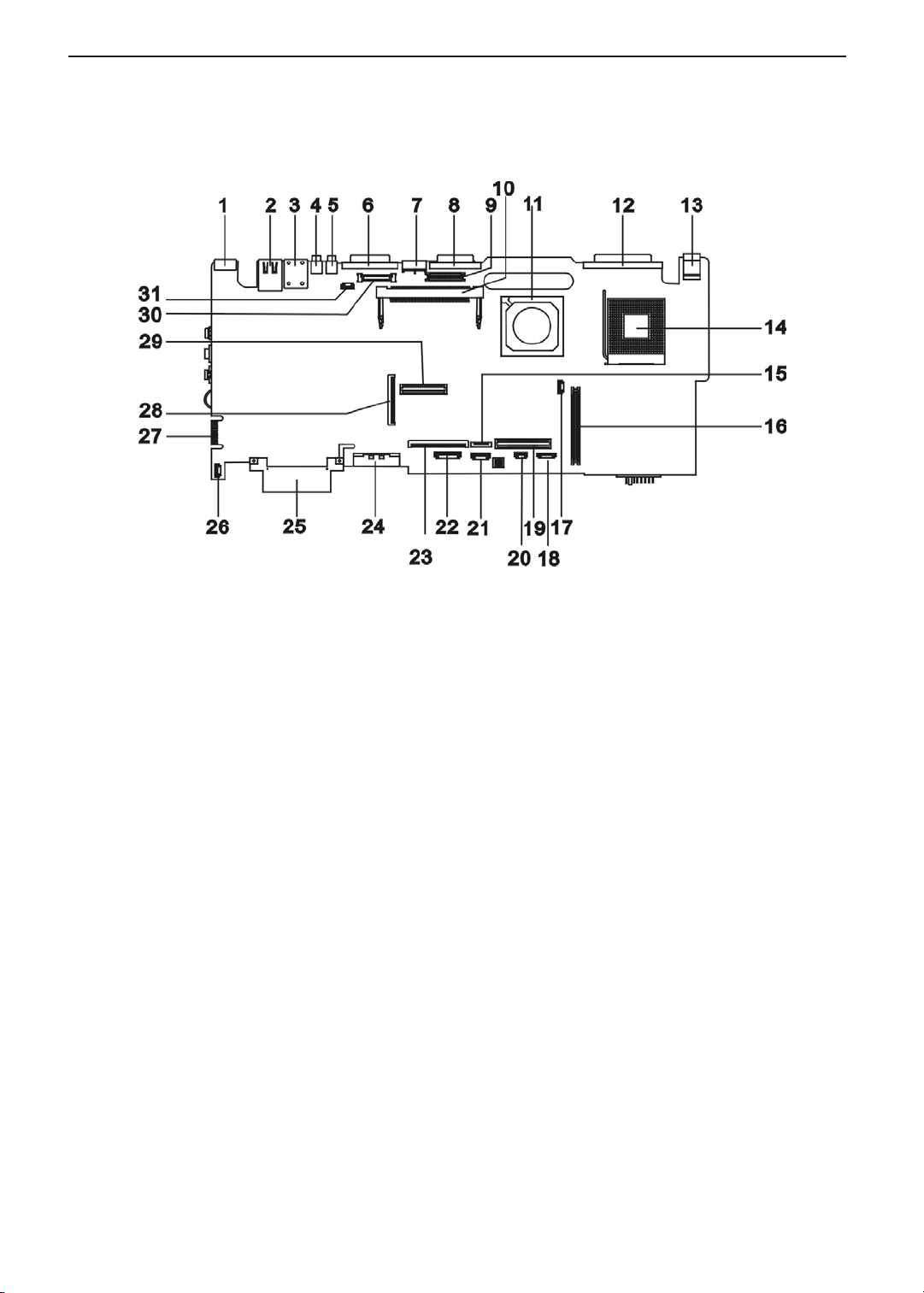
Board Layout
Top Vi ew
PCB No. : 02201-SB
1 PS/2 keyboard/mouse port 17 FAN Connector
2 LAN port 18 Finger Printer (Dummy)
3 Modem Port 19 DC to DC Connector
4 USB Port 20 RTC Connector
5 USB Port 21 FIR Connector (Dummy)
6 Serial Port 22 Bluetooth Connector (Dummy)
7 S-Video Connector 23 Keyboard Connector
8 External Display Port 24 Secondary IDE Connector
9 Inverter Connector 25 Primary IDE Connector
10 Mini-PCI Connector 26 Speaker Connector
11 SiSM650 27 Debug Board Connector
12 Parallel Port 28 Floppy Diskette Drive Connector
13 DC-in Port 29 DC to DC Connector
14 CPU Socket 30 LCD Monitor Connector
15 Touchpad Connector 31 Power Button
16 Cardbus Connector
3
Page 12
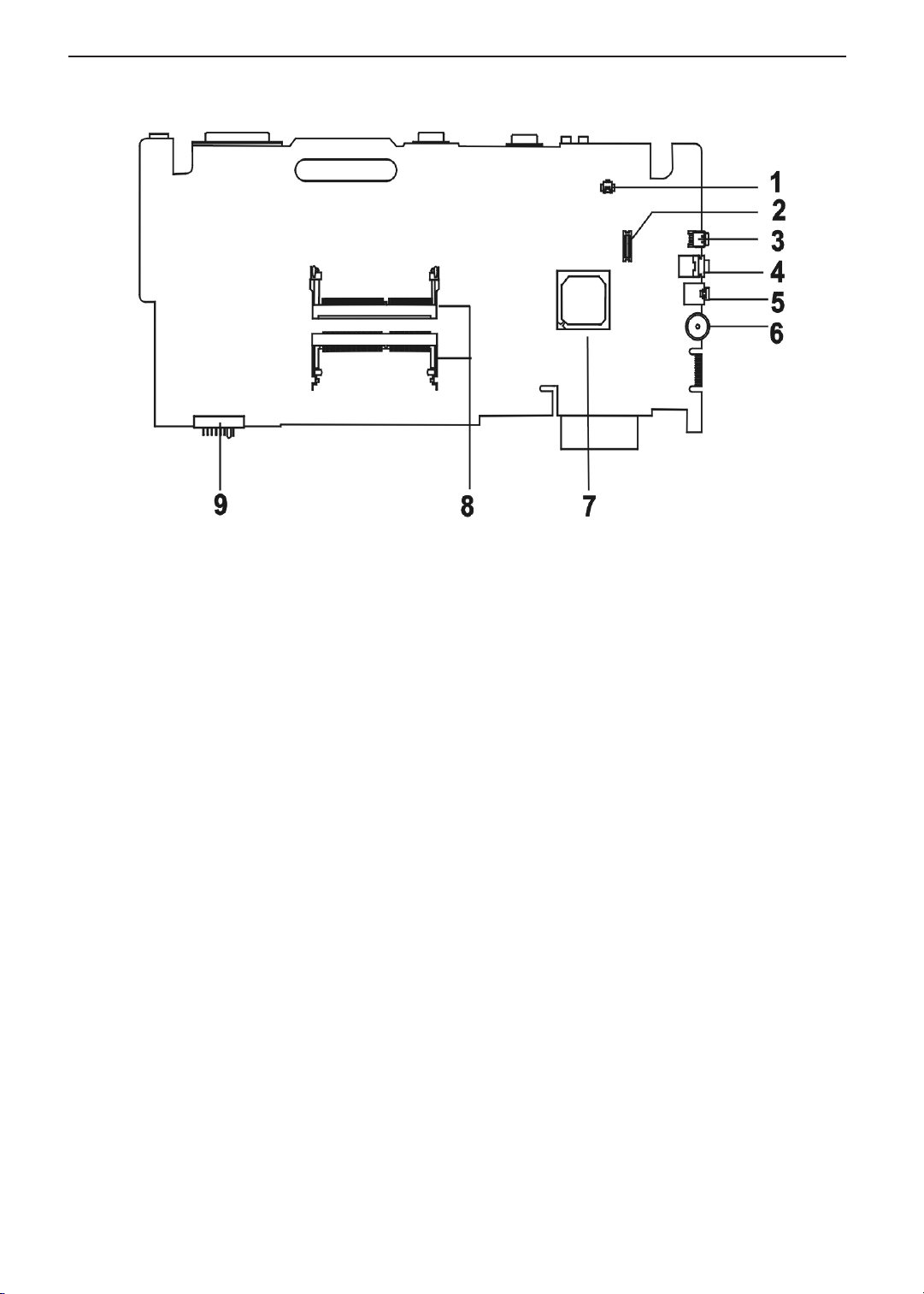
Bottom View
TECHNICAL SERVICE MANUALPrestigio Signore 152
1 Modem Card Cable Connector 6 Volume Controller
2 Modem Card Connector 7 SiS962
3 IEEE 1394 Port 8 Memory Slot 1
Memory Slot 2
4 Speaker Out Port 9 Battery Connector
5Line-in Port
4
Page 13
TECHNICAL SERVICE MANUAL Prestigio Signore 152
Outlook View
A general introduction of ports allow you to connect peripheral devices, as you would with a desktop PC.
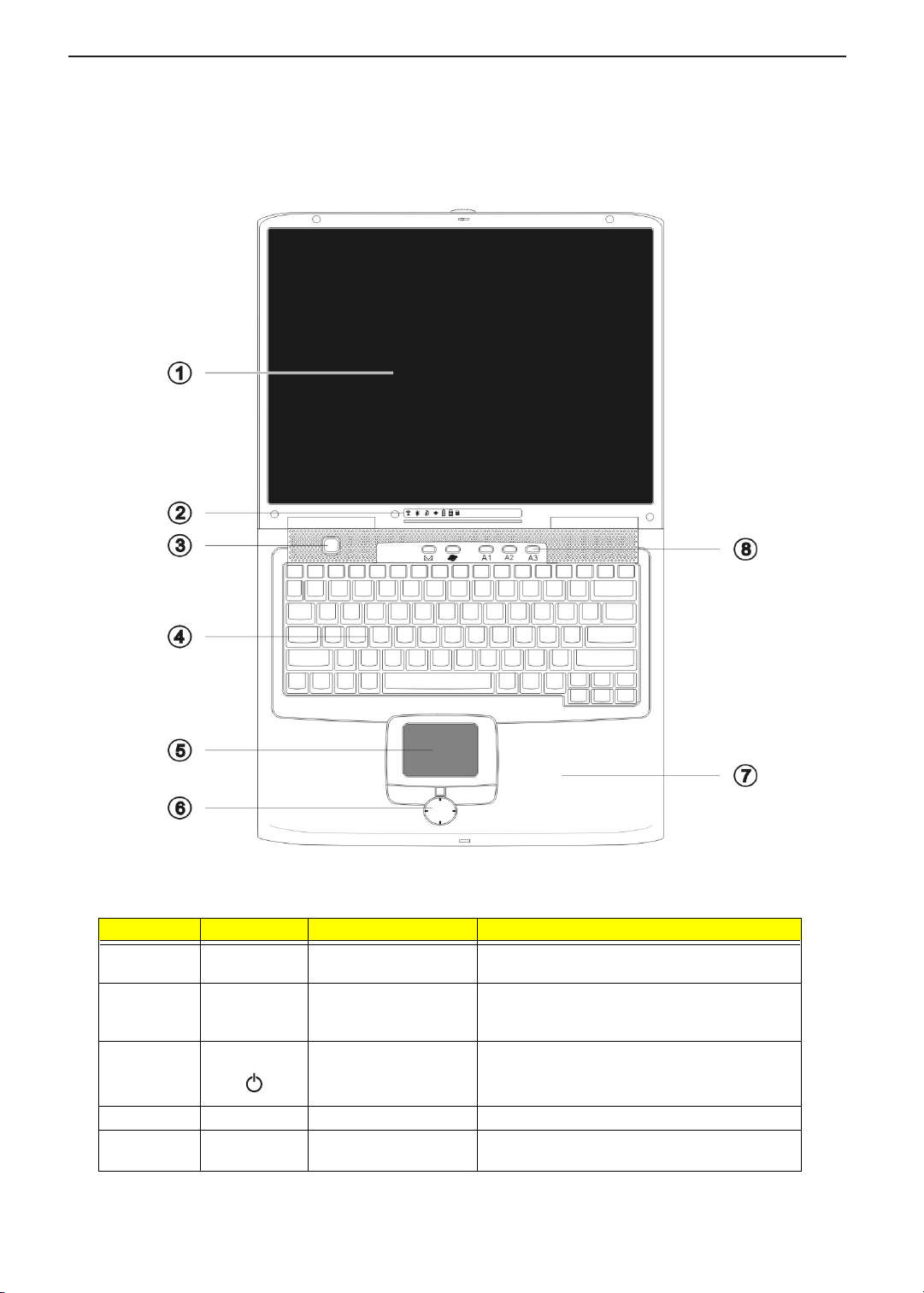
Top Vi ew
# Icon Item Description
1 Display screen Also called LCD (liquid-crystal display), displays
computer output.
2 Status indicators LEDs (Light-emitting diodes) that turn on and off to
show the status of the computer and its functions
and components.
3 Power button Turns of the computer power.
4 Keyboard Inputs data into your computer.
5 Touchpad Touch-sensitive pointing device which functions like
a computer mouse.
5
Page 14
# Icon Item Description
6 Click buttons (left, center
7 Palmrest Comfortable support area for your hands when you
8 Easy Launch keys Buttons for launching frequently used programs.
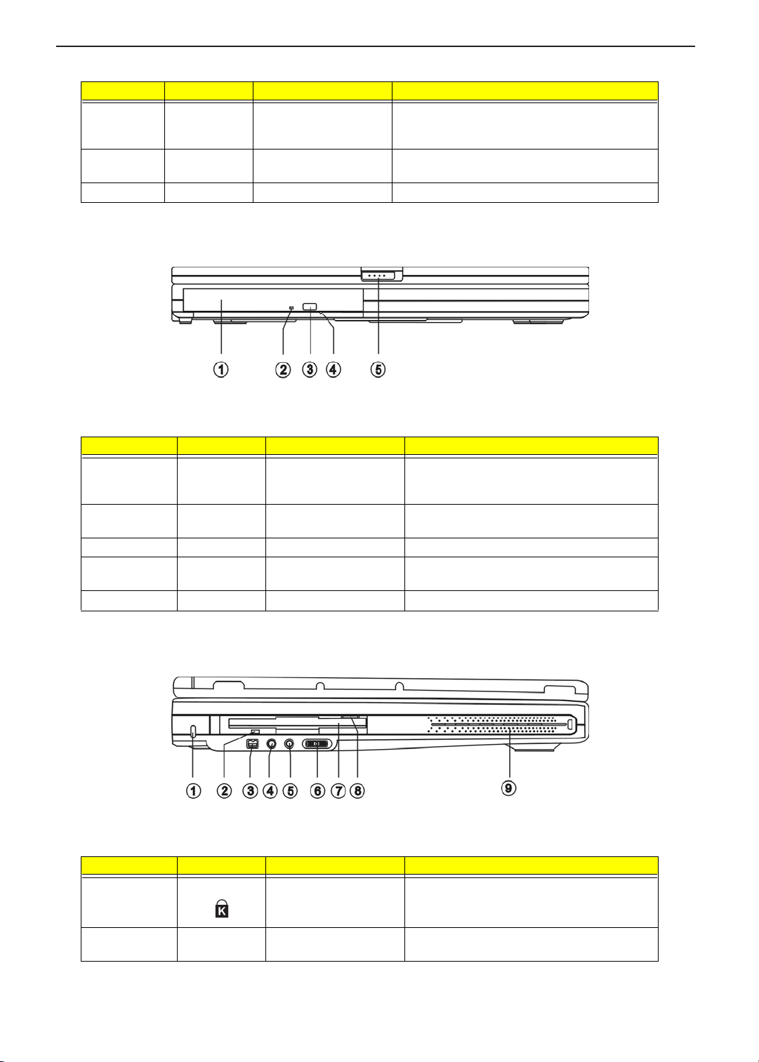
Front View
and right)
TECHNICAL SERVICE MANUALPrestigio Signore 152
The left and right buttons function like the left and
right mouse buttons. The center button is a fourdirectional scroll pad.
use the computer.
# Icon Item Description
1 Media bay module Installed in the Media bay, provides optical media
2 Optical drive activity
3 Optical drive eject button Ejects the disc from the optical drive.
4 Optical drive emergency
5 Display latch Slide to the right to unlatch and open the display.
Left Panel
indicator
eject hole
access or secondary storage by way of
removable modules.
Lights/flashes when the optical drive is in use.
Ejects the disc from the optical drive when the
computer is turned off.
# Icon Item Description
1 Security keylock Connects to a Kensington-compatible computer
security lock.
2 Floppy drive activity
indicator
Lights when the floppy drive is in use.
6
Page 15
TECHNICAL SERVICE MANUAL Prestigio Signore 152
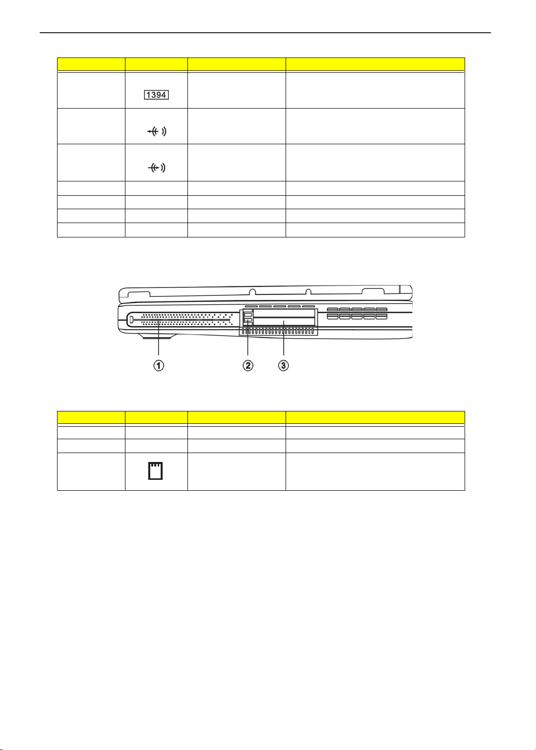
# Icon Item Description
3 IEEE 1394 port Connects to a IEEE 1394-compatible device
4 Line-out jack Connects to audio line-out devices (e.g.,
5 Line-in jack Connects an external microphone or an external
6 Volume control knob Controls the volume of the speakers.
7 Floppy drive Accepts a 3.5-inch diskette.
8 Floppy drive eject button Ejects the diskette from the floppy drive.
9 Speaker (left) Outputs sound.
(e.g., digital video camera).
speakers, headphones).
audio line-in device.
Right Panel
# Icon Item Description
1 Speaker (right) Outputs sound.
2 PC Card eject button Eject the PC Card from its slot.
3 PC Card slots Accepts one type III or two II/I PC Card(s).
7
Page 16
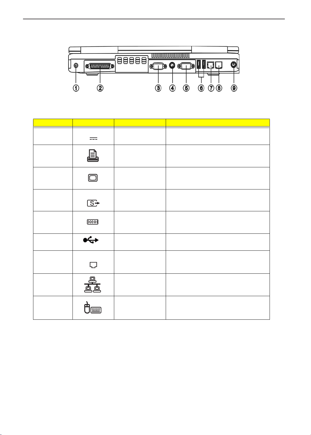
Rear Panel
# Icon Item Description
1 DC-in jack Connects to an AC adapter.
2 Parallel port Connects to a parallel device (e.g., parallel
3 External monitor port Connects to a display device.
TECHNICAL SERVICE MANUALPrestigio Signore 152
printer).
4 Video-out port Connects to a display device with S-video input.
5 Serial port Connects to a serial device (e.g., serial mouse).
6 USB ports (t wo) Connect to Universal Serial Bus devices (e.g.,
USB mouse, USB digital camera).
7 Modem jack Connects to a phone line (only for models with
8 Network jack Connects to an Ethernet 10/100-based network.
9 PS/2 port Connects to any PS/2-compatible device (e.g.,
an internal fax/data modem).
PS/2 mouse/keyboard/keypad).
8
Page 17
TECHNICAL SERVICE MANUAL Prestigio Signore 152
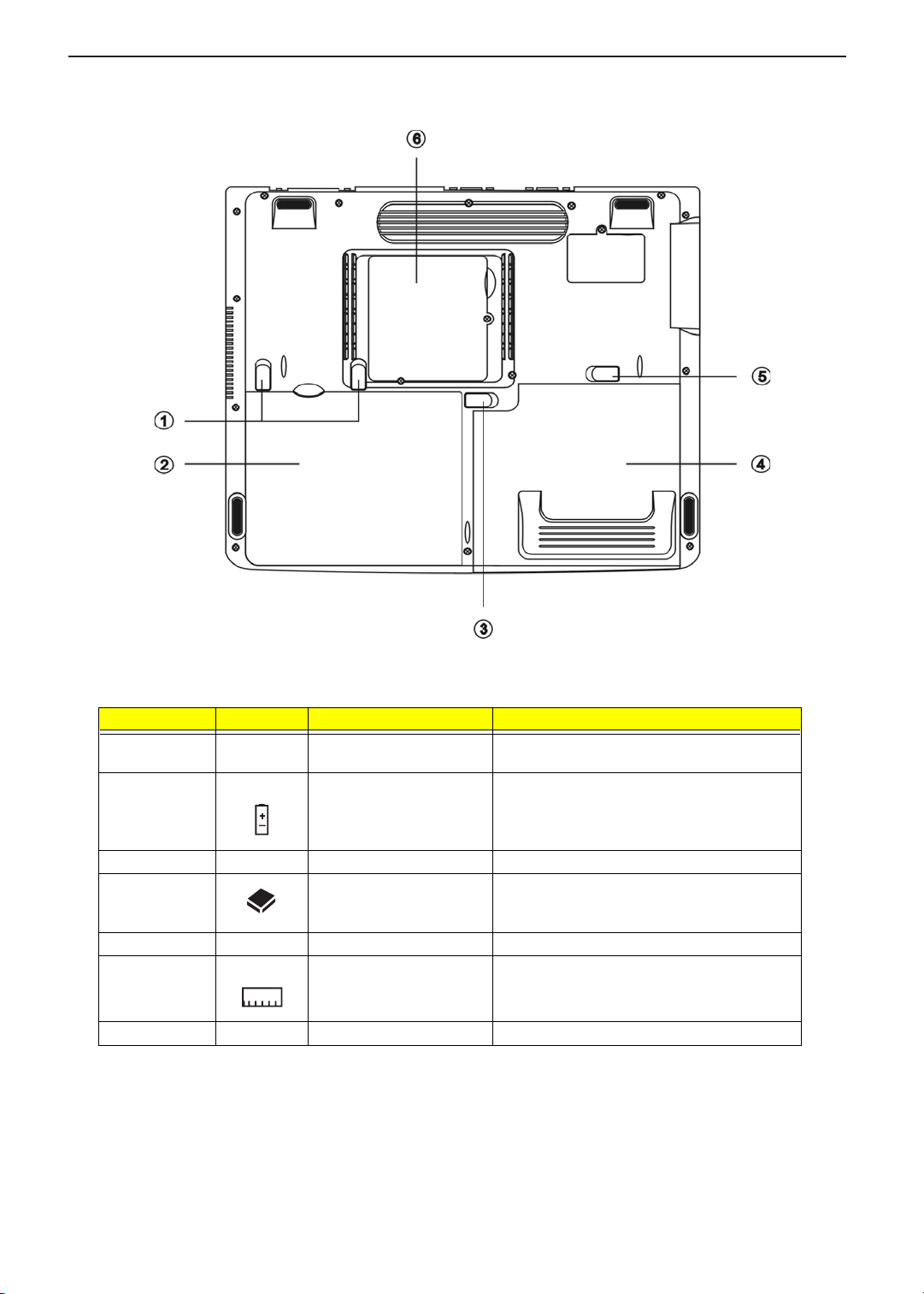
Bottom Panel
# Icon Item Description
1 Battery release latches Unlatches the battery to remove the battery
pack.
2 Battery Houses the computer’s battery pack.
3 Battery lock Locks/unlocks the battery pack in the battery bay.
4 Media bay Module Installed in the Media bay, provides optical media
access or secondary storage by way of
removable modules.
5 Media bay release latch Unlatches the Media bay module.
6 Memory compartment Houses the computer’s main memory.
7 MDC compartment Houses the computer’s modem card.
9
Page 18
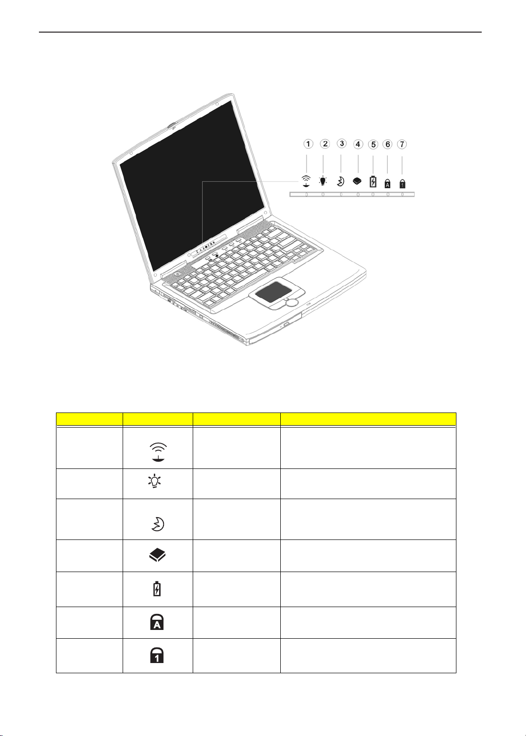
Indicators
The computer has seven easy-to-read status icons on the right of the display screen.
TECHNICAL SERVICE MANUALPrestigio Signore 152
The Power and Standby status icons are visible even when you close the display cover so you can see the
status of the computer while the cover is closed.
# Icon Function Description
1 Wireless
communication
2 Power Lights when the computer is on;
3 Sleep Lights when the computer enters Sleep mode’
4 Media activity Flashes when the hard disk or optical drive is
4 Battery charge Lights when the battery is being charged.
5 Caps lock Lights when Caps Lock is activated.
Lights when the Wireless connection is active.
flashes when a battery-low condition occurs.
flashes when the computer is waking up from
Sleep mode.
accessed.
6 Num lock Lights when Numeric Lock is activated.
10
Page 19
TECHNICAL SERVICE MANUAL Prestigio Signore 152
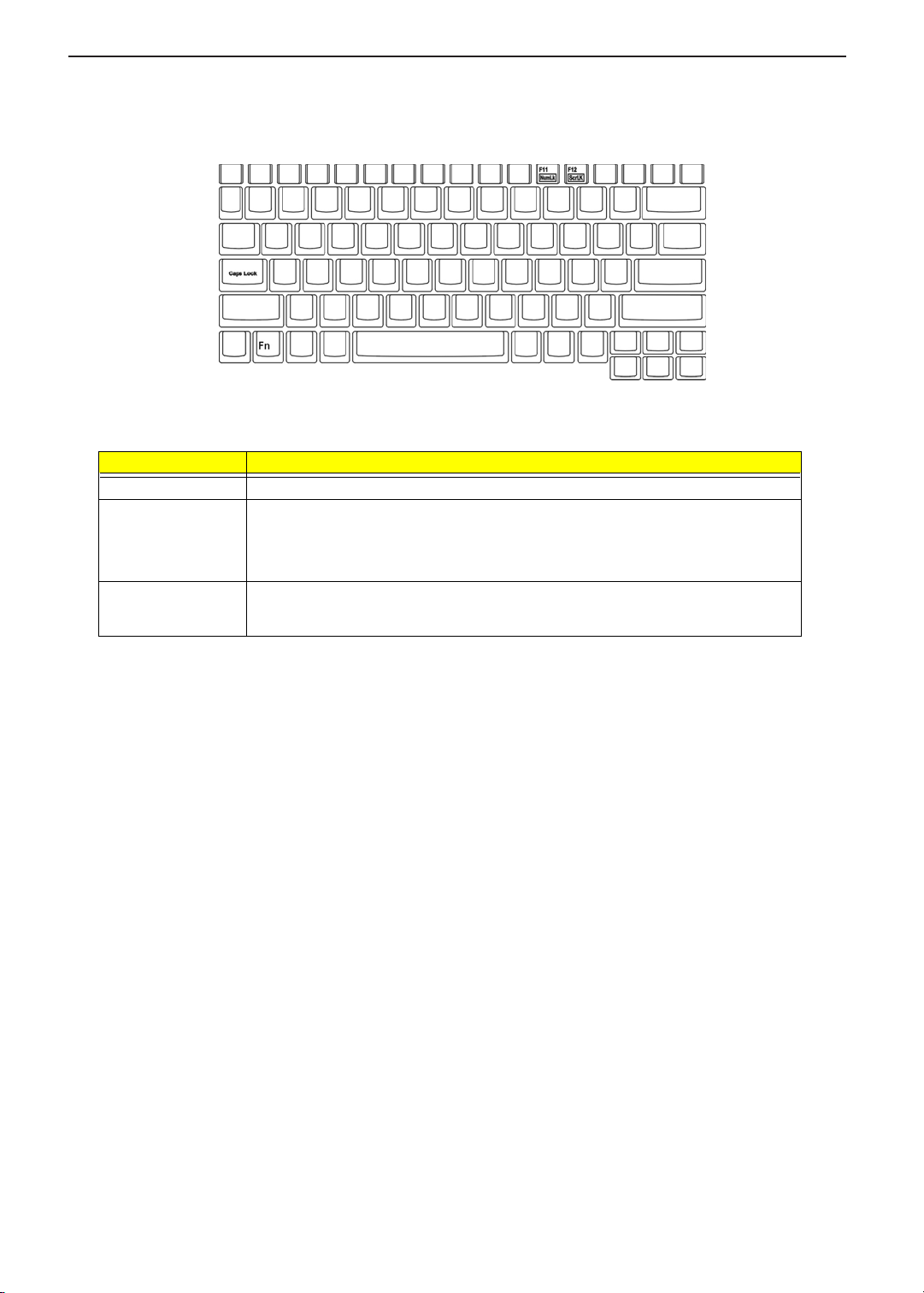
Lock Keys
The keyboard has three lock keys which you can toggle on and off.
Lock Key Description
Caps Lock When Caps Lock is on, all alphabetic characters typed are in uppercase.
] (Fn-F11) When ] is on, the embedded keypad is in numeric mode. The keys function as a
calculator (complete with the arithmetic operators +, -, *, and /). Use this mode when you
need to do a lot of numeric data entry. A better solution would be to connect an external
keypad.
[(Fn-F12) When [ is on, the screen moves one line up or down when you press the
arrow keys respectively.
[ does not work with some applications.
w
or y
11
Page 20
TECHNICAL SERVICE MANUALPrestigio Signore 152
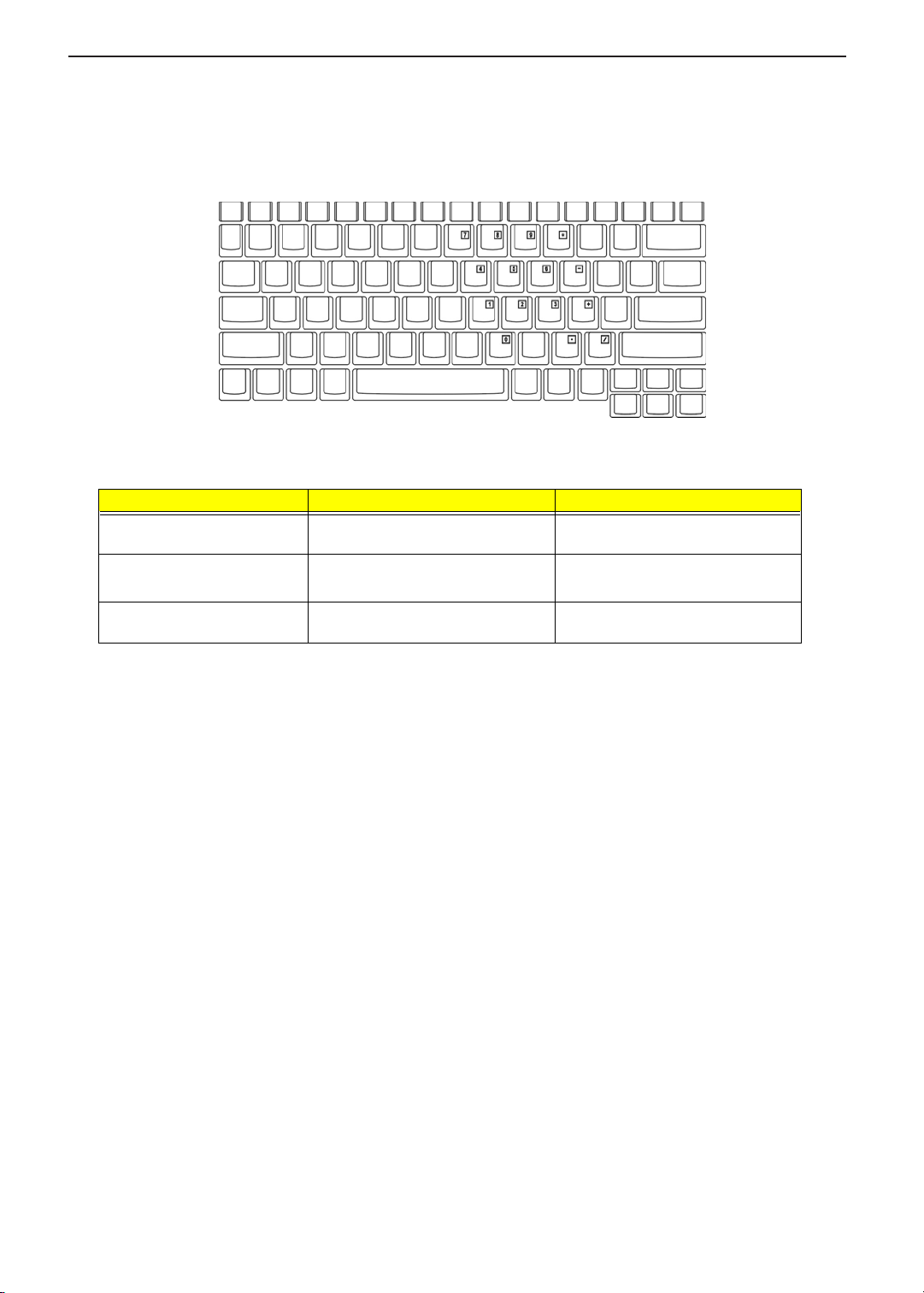
Embedded Numeric Keypad
The embedded numeric keypad functions like a desktop numeric keypad. It is indicated by small characters
located on the upper right corner of the keycaps. To simplify the keyboard legend, cursor-control key symbols
are not printed on the keys.
Desired Access Num Lock On Num Lock Off
Number keys on embedded
keypad
Cursor-control keys on
embedded keypad
Main keyboard keys Hold Fn while typing letters on
Type numbers in a normal manner.
j while using cursor-control
Hold
keys.
embedded keypad.
j while typing numbers.
Hold
Use cursor-control keys in a normal
manner.
Type the letters in a normal manner.
NOTE: If an external keyboard or keypad is connected to the computer, the Num Lock feature automatically
shifts from the internal keyboard to the external keyboard or keypad.
12
Page 21
TECHNICAL SERVICE MANUAL Prestigio Signore 152
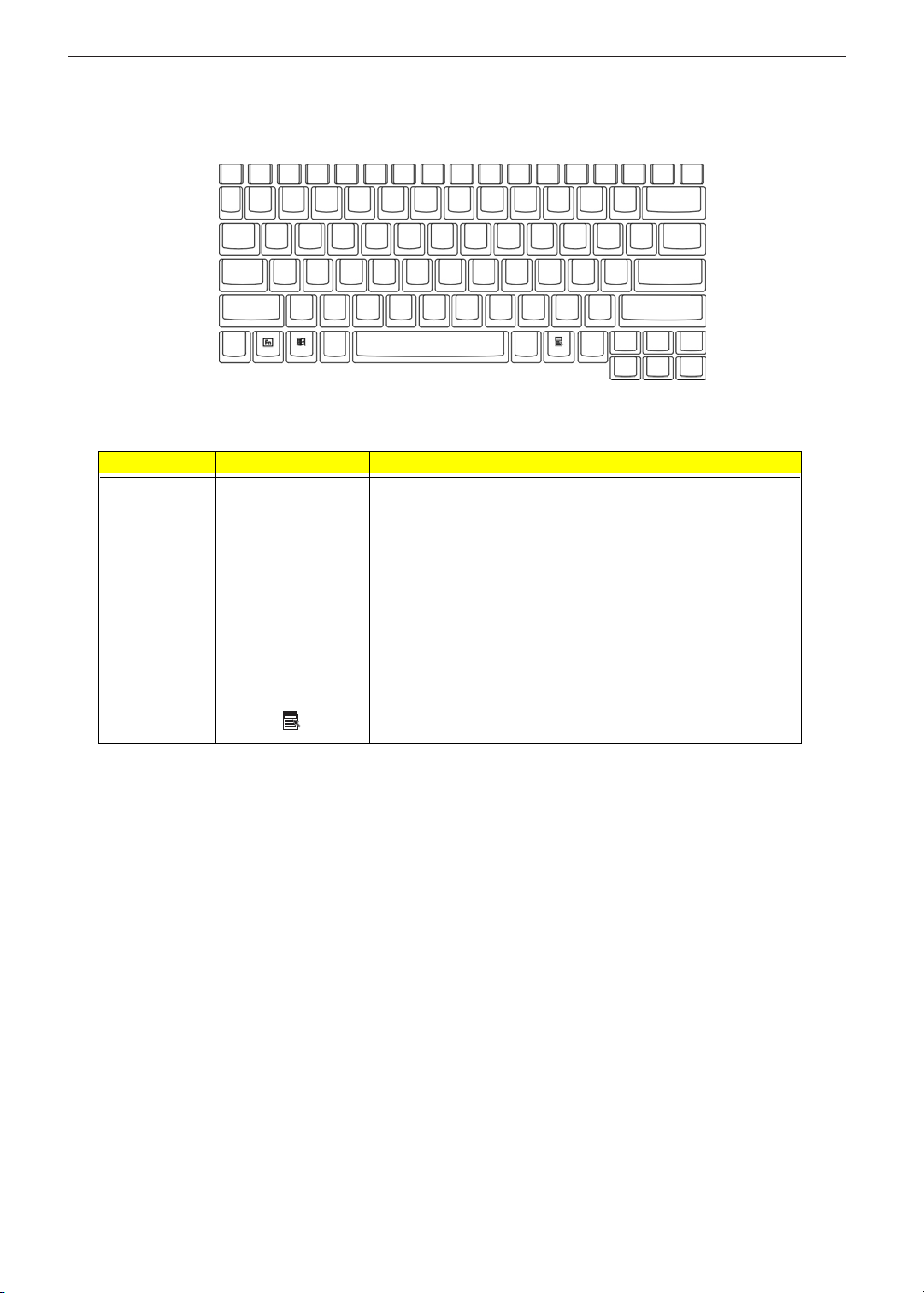
Windows Keys
The keyboard has two keys that perform Windows-specific functions.
Key Icon Description
Windows logo
key
Application key
(Fn-Application
key)
á
Start button. Combinations with this key perform shortcut functions.
Below are a few examples:
+ Tab (Activates next taskbar button)
á
+ E (Explores My Computer)
á
+ F (Finds Document)
á
+ M (Minimizes All)
á
j
+ á + M (Undoes Minimize All)
+ R (Displays the Run...dialog box)
á
Opens the application’s context menu (same as a right-click).
13
Page 22
TECHNICAL SERVICE MANUALPrestigio Signore 152
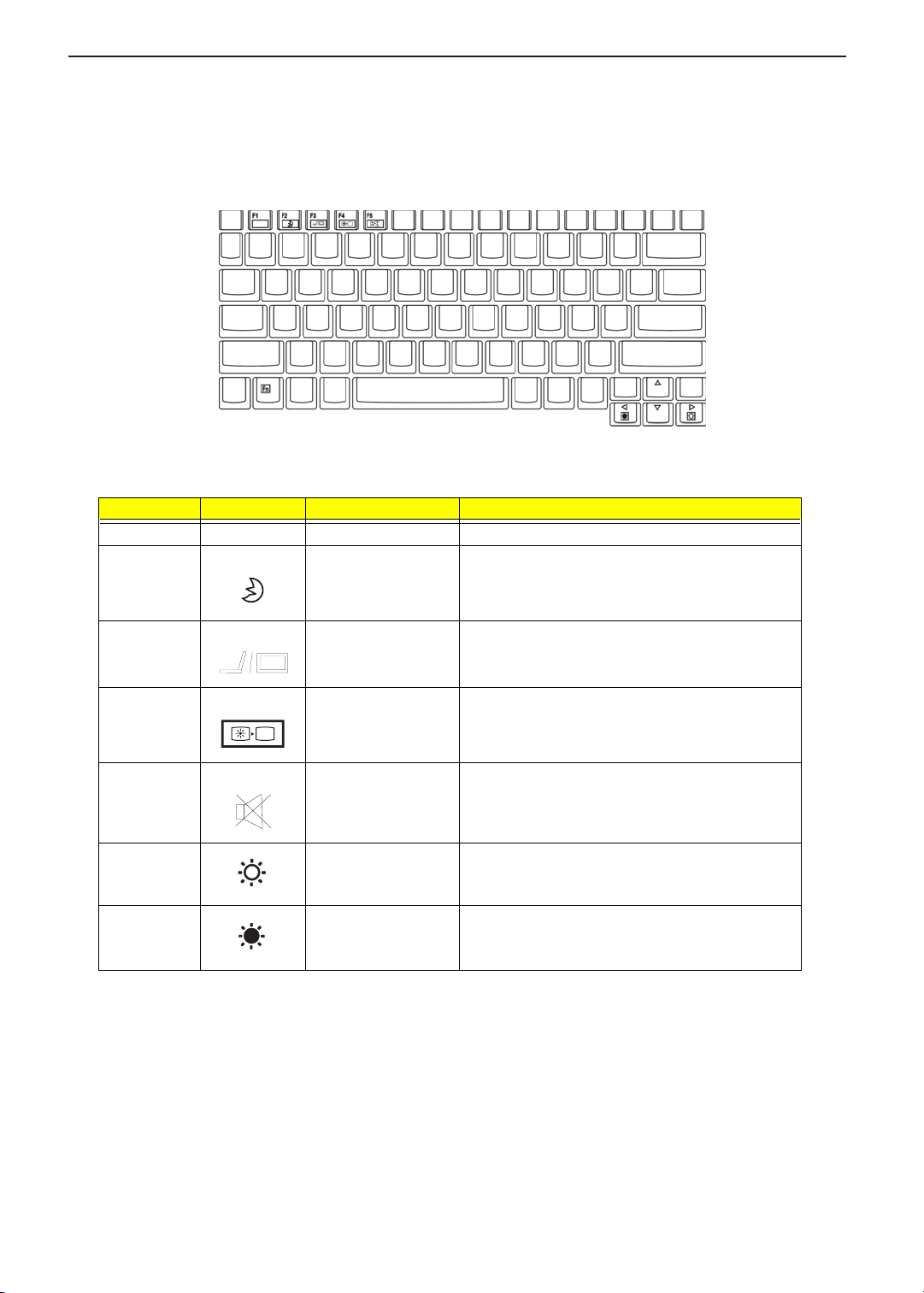
Hot Keys
The computer employs hot keys or key combinations to access most of the computer’s controls like screen
contrast and brightness, volume output and the BIOS Utility.
To activate hot keys, press and hold the Fn key before pressing the other key in the hot key combination.
Hot Key Icon Function Description
Fn-F1 Hot key Help Menu Displays a list of the hotkeys and their functions.
Fn-F2 Sleep Button Puts the computer in Sleep mode, which can be
defined via the advanced section of the Power
Management Properties in the Windows Control
Panel.
Fn-F3 Display toggle Switches display output between the display screen,
external monitor (if connected) and both the display
screen and external monitor.
Fn-F4 Screen blank Turns the display screen backlight off to save power.
Fn-F5 Speaker on/off Turns the speakers on and off; mutes the sound.
Fn-→ Brightness up Increases the screen brightness.
Fn-
←
Brightness down Decreases the screen brightness.
Press any key to return.
14
Page 23
TECHNICAL SERVICE MANUAL Prestigio Signore 152
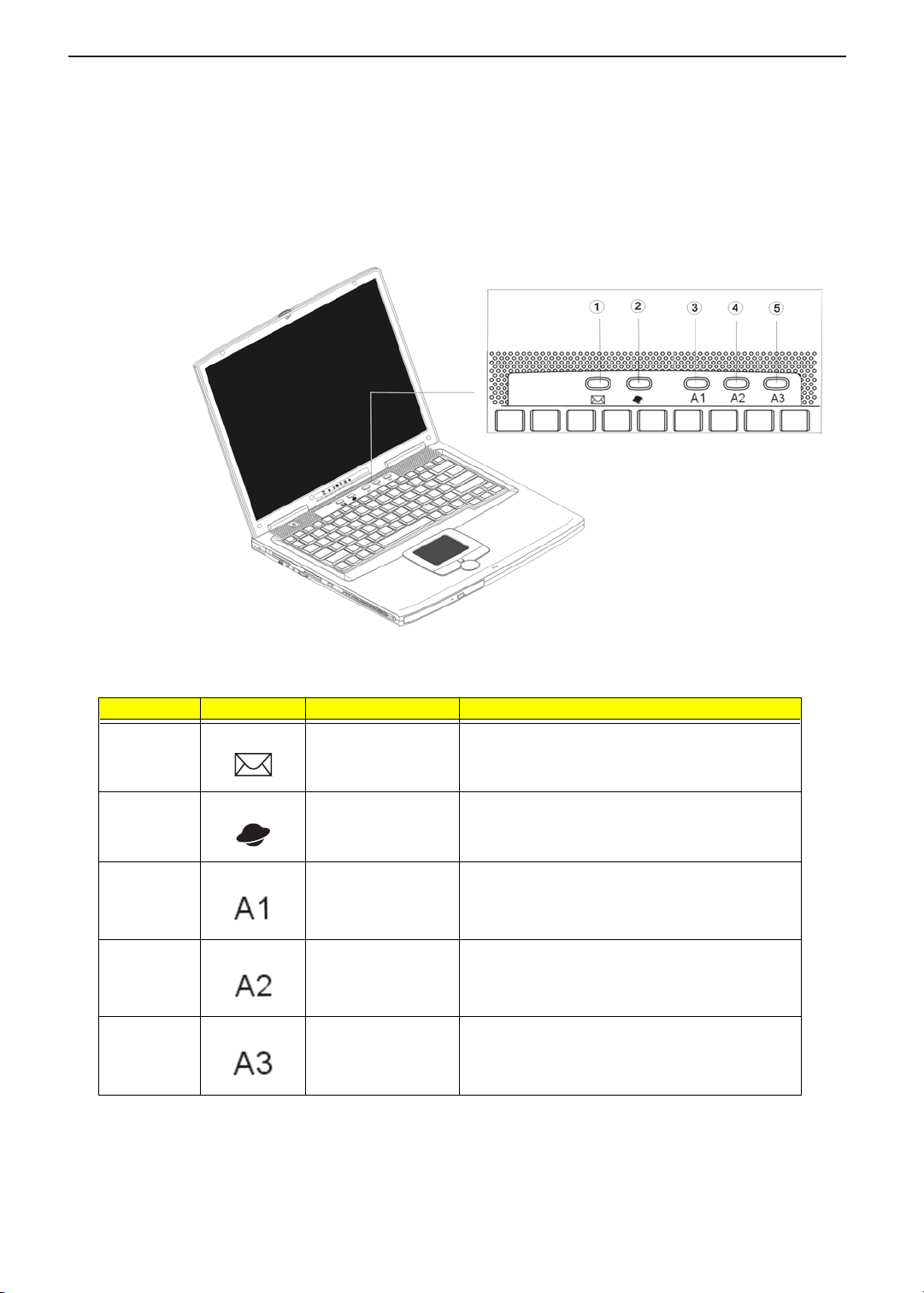
Launch Keys
Located at the top of the keyboard are five launch keys. Used to launch frequently used applications, these
launch keys are designated as Mail, Web, A1 and A2 and A3.
Number Icon Function Description
1 Email By default, is used to launch the email application;
lights when incoming email is received.
2 Internet browser By default, is used to launch your internet browser
application.
3 A1 This button is user-programmable.
4 A2 This button is user-programmable.
5 A3 This button is user-programmable.
15
Page 24
TECHNICAL SERVICE MANUALPrestigio Signore 152
Hardware Specifications and Configurations
Processor
Item Specification
CPU type
CPU package Micro-PGA2 478 pin package
CPU core voltage 1.45V/1.75V (max)
CPU VID voltage 1.2V
BIOS
Item Specification
BIOS vendor Phoenix
BIOS Version R01-C5
BIOS ROM type Flash ROM
BIOS ROM size 512KB
BIOS package 32-pin
Supported protocols ACPI 1.0b/ 2.0, HDD Password, INT 13h Extensions, Boot Block, Simple
BIOS password control Set by switch, see SW1 setting
®
Intel
PIV Northwood 0.13u desktop processor from 2.0GHz up to 2.4GHz
, integrated with 512KB L2 cache
Boot Flag Specification 1.0, PnP BIOS 1.0a, PCI 2.2, USB 1./ 2.0, DTMF
Desktop Management, SMBIOS 2.3, IEEE 1394 V1.0, WfM 2.0 (for build in
Ethernet model, PCMCIA V3.0 compliant device.
Second Level Cache
Item Specification
Cache controller CPU
Cache size 512KB
1st level cache control Always enabled
2st level cache control Always enabled
Cache scheme control Fixed in write-back
System Memory
Item Specification
Memory controller Built-in SiSM650
Onboard memory size 0MB
DIMM socket number 2 sockets (2 banks)
Supports memory size per socket 128/ 256/ 512MB (DDR 266)
Supports maximum memory size 512MB X2
Supports DIMM type DDR SDRAM
Supports DIMM Speed 133 MHz
Supports DIMM voltage 2.5V
Supports DIMM package 144-pin
Memory module combinations You can install memory modules in any combinations as long as they
match the above specifications.
16
Page 25
TECHNICAL SERVICE MANUAL Prestigio Signore 152
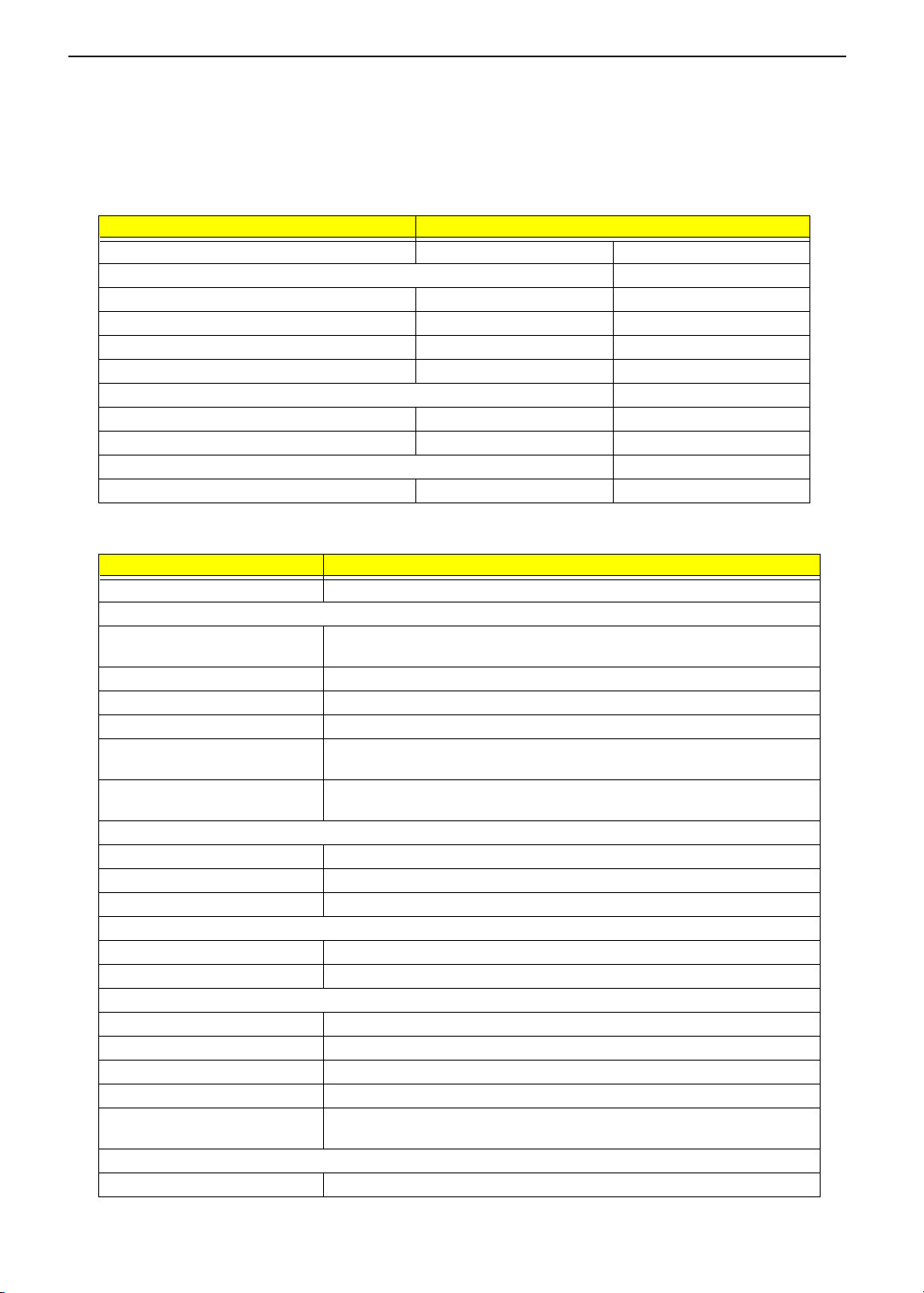
Memory Combinations
DIMM I DIMM II Total M emory
128 MB 0 MB 128 MB
0 MB 128 MB 128 MB
128 MB 128 MB 256 MB
256 MB 0 MB 256 MB
0 MB 256 MB 256MB
128 MB 256 MB 384 MB
256MB 128 MB 384 MB
256 MB 256 MB 512 MB
512 MB 0MB 512 MB
0 MB 512 MB 512 MB
128 MB 512 MB 640 MB
512 MB 128 MB 640 MB
256 MB 512 MB 768 MB
512 MB 256 MB 768 MB
512 MB 512 MB 1024MB
Above table lists some system memory configurations. You may combine DIMMs with various capacities to
form other combinations.
Modem Interface
Item Specification
Chipset Agere MDC
Fax modem data baud rate (bps) 14.4K
Data modem data baud rate (bps) 56K
Supports modem protocol V.92 56K fax/ modem
Modem connector type RJ11
Modem connector location Rear side
LAN Interface
Item Specification
Chipset Realtek 8100BL
Supports LAN protocol 10/100 Mbps
LAN connector type RJ45
LAN connector location Rear side
Wireless LAN Interface
Item Specification
Module Lucent/ANC 64 bit AGERE W/RES
LAN interface Mini PCI interface IEEE 802.11b LAN module
Channel support and default channel protocol IEEE 802.11b
Enable/disable radio Support FAA requirement
17
Page 26
TECHNICAL SERVICE MANUALPrestigio Signore 152
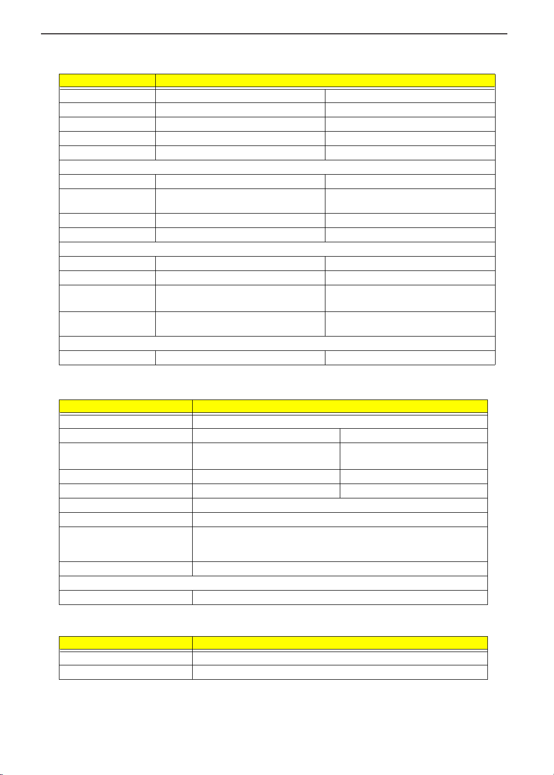
Hard Disk Drive Interface
Item Specification
Vendor & Model name Toshiba MK3018GAS Toshiba MK4018GAS
Capacity (GB) 30000 40000
Bytes per sector 512 512
Logical heads 16 16
Logical sectors 63 63
Drive Format
Logical cylinders 16383 16383
Physical read/write
heads
Disks 2 2
Spindle speed (RPM) 5400 5400
Performance Specifications
Buffer size 16348KB 16348KB
Interface ATA-2/3/4/5 ATA-2/3/4/5
Data transfer rate
(disk-buffer, Mbytes/s)
Data transfer rate
(host~buffer, Mbytes/s)
DC Power Requirements
Voltage tolerance 5V(DC) +/- 5% 5V(DC) +/- 5%
34
200.8~333.2(max) 200.8~333.2(max)
100MB/Sec 100MB/Sec
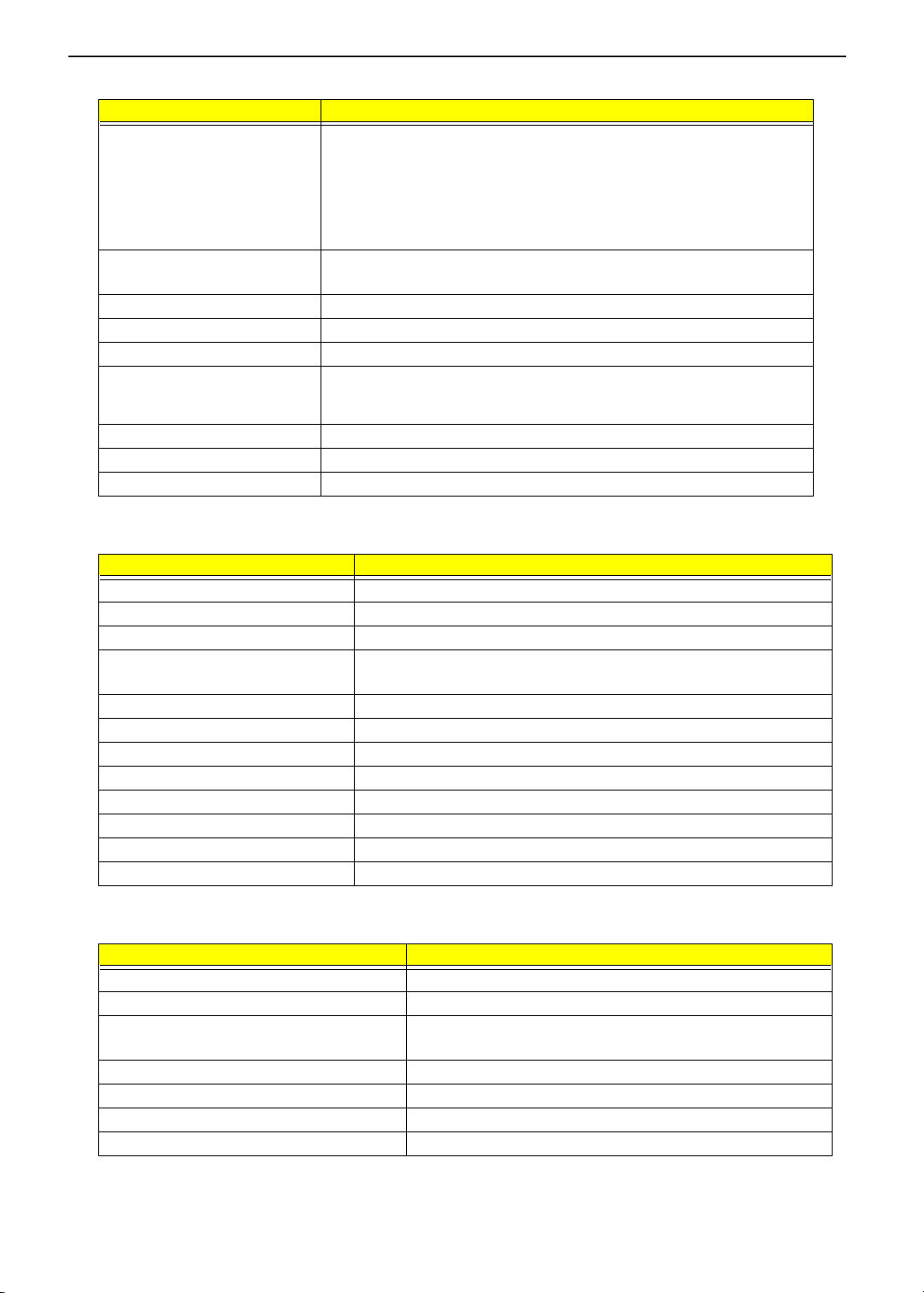
DVD/CD-RW Combo
Item Specification
Vendor & model name SONY CRX-801E
Performance specification With CD Diskette With DVD Diskette
Transfer rate (KB/sec) 1,500KB/sec. ~ 3,600KB/sec.
(FULL - CAV)
Access time (typ.) 110 ms 150 ms
Rotation speed 4800 rpm (typ.) 3700 rpm (typ.)
Buffer memory 512 KBytes
Interface ATAPI
Applicable disc format DVD-ROM, DVD-Video, CD-DA, CD-ROM (Mode-1, Mode-2), CD-ROM XA
Mode-2 (FORM-1, FORM-2), Multi-Session Photo CD, CD-I, Video CD,
Enhanced CD & CD PLUS Compatible, CD-R/W
Loading mechanism Drawer with soft eject and emergency eject hole
Power Requirement
Input voltage 5V(DC) +/- 5%
4.58MB/sec. ~ 11.08MB/sec.
(FULL - CAV)
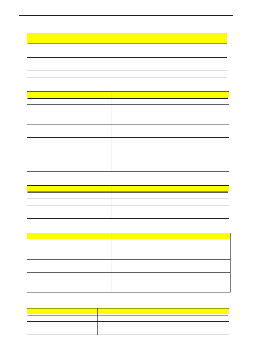
CD-RW Module
Item Specification
Vendor & Model name KME-UJDA360
Performance Specification
18
Page 27
TECHNICAL SERVICE MANUAL Prestigio Signore 152
CD-RW Module
Item Specification
Transfer rate (KB/sec) CAV Mode:
775~1800 blocks/sec
Mode 1:
1550-3600 KBytes/sec
Mode 2:
1768~4106 KBytes/sec
Access time (typ.) Random: 150 ms
Full Stroke: 300 ms
Rotation speed 5000 rpm (typ.)
Buffer memory 2MB
Interface ATAPI
Applicable disc format CD-DA, CD-ROM (Mode-1, Mode-2), CD-ROM XA Mode-2 (FORM-1, FORM-
2), Multi-Session Photo CD, CD-I, Video CD, Enhanced CD & CD PLUS
Compatible, CD-R/W
Loading mechanism Drawer with soft eject and emergency eject hole
Power Requirement
Input voltage 5V(DC) +/- 5%
Audio Interface
Item Specification
Audio Controller Cirrus CS4299-XQ with S/PDIF function
Audio onboard or optional Built-in
Mono or Stereo Stereo
Resolution 20 bit stereo Digital to analog converter
18 bit stereo Analog to Digital converter
Compatibility AC97 2.1
Mixed sound source Line-in, CD, Video, AUX
Voice channel 8/16-bit, mono/stereo
Sampling rate 44.1 KHz
Internal microphone Yes
Internal Headphone Yes
Internal speaker / Quantity Yes/ 2
Supports PnP IRQ IRQ11
Video Interface
Item Specification
Chip vendor SIS
Chip name SiSM650+SiS302LV
Chip voltage Core/3.3V
Memory/2.5V
Supports ZV (Zoomed Video) port No
Graph interface VB (Video Bridge) Bus
Maximum resolution (LCD) 14.1”/ 15”-1024x768 (32 bit colors)
Maximum resolution (CRT) 1600x1200 (32 bit colors)
19
Page 28
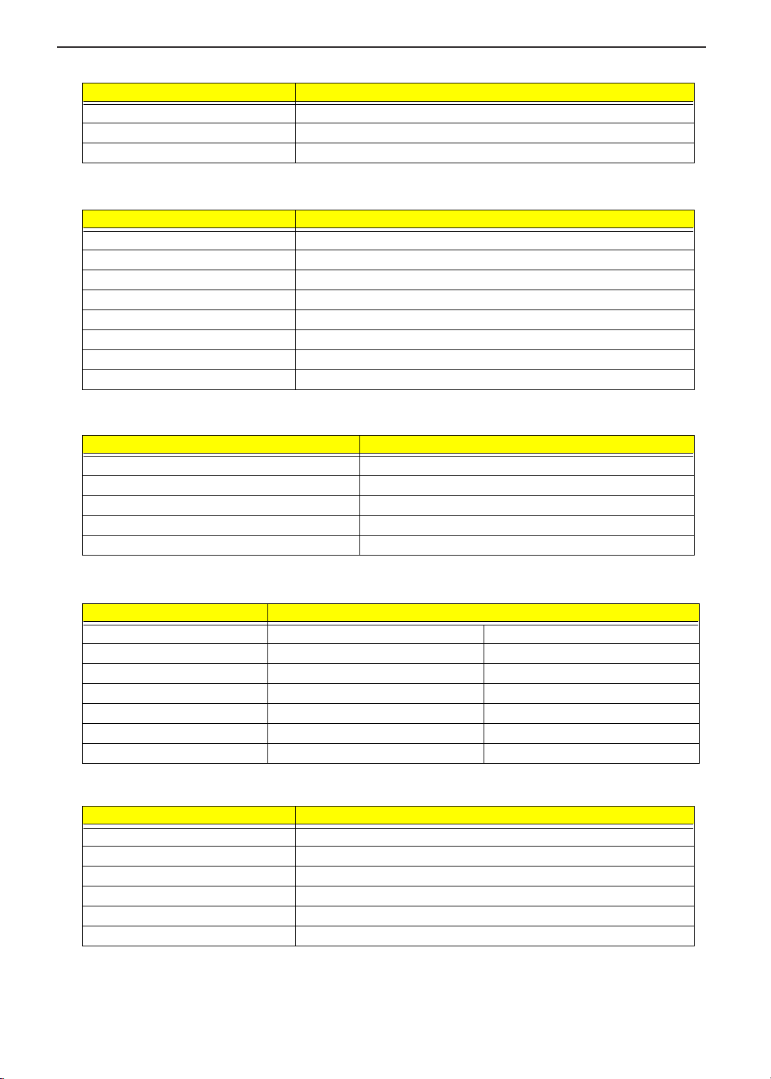
Video Resolutions Mode (for 14”/ 15” XGA LCD)
TECHNICAL SERVICE MANUALPrestigio Signore 152
Resolution
640x480 Yes Yes Yes
800x600 Yes Yes Yes
1024x768 Yes Yes Yes
1600X1200 (CRT only) Yes Yes Yes
1024X768 (TV) Yes Yes Yes
8 bits
(256 colors)
16 bits
(High color)
Parallel Port
Item Specification
Parallel port controller SIO NS87392
Number of parallel port 1
Location Rear side
Connector type 25-pin D-type connector, in female type
Parallel port function control Enable/Disable by BIOS Setup
Supports ECP Yes (set by BIOS setup)
Optional ECP DMA channel
(in BIOS Setup)
Optional parallel port I/O address
(in BIOS Setup)
Optional parallel port IRQ
(in BIOS Setup)
DMA channel 1 or 3
378, 278
IRQ7
32 bits
(True color)
USB Port
Item Specification
USB Compliancy Level 1.1/ 2.0
OHCI USB 1.1/ 2.0
Number of USB port 2
Location Rear side
Serial Port
Item Specification
Serial port controller NS87392
Number of serial port 1
Supports 16550 UART Yes
Connector type 9 pin D-sub connector (male)
Location Rear side
Serial port function control Enable/Disable by BIOS Setup
Optional serial port (in BIOS Setup) 3F8h, 2F8h, 3E8h, 2E8h
Optional serial port IRQ (in BIOS Setup) IRQ3
PCMCIA Port
Item Specification
PCMCIA controller TI PCI1520
Supports card type Type-II/ III
Number of slots One type-III/ two type II
20
Page 29
TECHNICAL SERVICE MANUAL Prestigio Signore 152
PCMCIA Port
Item Specification
Access location Right side
Supports ZV (Zoomed Video) port No ZV support
Supports 32 bit CardBus Yes (IRQ10)
System Board Major Chips
Item Controller
System core logic SiSM650
Super I/O controller NS87392
Audio controller CS4299-XQ
Video controller NorthBridge (SiSM650) with integrated 2D/3D engine
Hard disk drive controller SiS962
Keyboard controller M38859
PCMCIA controller TI1520
RTC SiS962 (embedded)
Keyboard
Item Specification
Keyboard controller NSK A7001
Keyboard vendor & model name Darfon
Total number of keypads 88-key PS/2 and AT-compatible
Windows 95 keys Yes
Internal & external keyboard work simultaneously Yes
Battery
Item Specification
Vendor & model name Sony BTP-46A3 Sanyo BTP-47A3
Battery Type Li-ion Ni-MH
Pack capacity 5880 mAH 4500 mAH
Cell voltage 3.7V (Typical) 1.2V (Typical)
Number of battery cell 12 10
Package configuration 4 cells in series, 3 series in parallel 10S
Package voltage 14.8 V (Typical) 12V (Typical)
DC-AC LCD Inverter
Item Specification
Vendor & model name Ambit T62l194.04
Input voltage (V) 7.3 ~ 21V
Input current (mA) 1000mA max
Output voltage (Vrms, no load) 1450Vrms
Output voltage frequency (kHz) 45K-80K Hz
Output Current/Lamp 6.0 mA max
NOTE: DC-AC inverter is used to generate very high AC voltage, then support to LCD CCFT backlight user,
and is also responsible for the control of LCD brightness. Avoid touching the DC-AC inverter area while
21
Page 30
TECHNICAL SERVICE MANUALPrestigio Signore 152
the system unit is turned on.
NOTE: There is an EEPROM in the inverter, which stores its supported LCD type and ID code. If you replace
a new inverter or replace the LCD with a different brand, use Inverter ID utility to update the ID
information.
LCD
Item Specification
Vendor & model name AU B141XN04V2 Hanstar HSD150PX11
Mechanical Specifications
LCD display area (diagonal, inch) 14.1 15”
Display technology TFT TFT
Resolution XGA (1024x768) XGA (1024x768)
Supports colors 262K 262K
Optical Specification
Brightness control Keyboard hotkey Keyboard hotkey
Contrast control No No
Electrical Specification
Supply voltage for LCD display (V) 3.3 3.3
AC Adapter
Item Specification
Vendor & model name LiteON PA-1121-02AC (3 pin)
Input Requirements
Maximum input current (A,
@90Vac, full load)
Nominal frequency (Hz) 50 - 60
Frequency variation range (Hz) 47 - 63
Nominal voltages (Vrms) 90 - 264
Inrush current The maximum inrush current will be less than 50A and 100A when the adapter
Efficiency It should provide an efficiency of 83% minimum, when measured at maximum
Output Ratings (CV mode)
DC output voltage +20V+1.5/-1V
Noise + Ripple 250mvp-pmax (20MHz bandwidth)
Load 0 A (min.) 6 A (max.)
Output Ratings (CC mode)
DC output voltage +8V ~ +20V
Constant output 7 ± 0.5 A
Dynamic Output Characteristics
Turn-on delay time 3 sec. (@115Vac)
Hold up time 8 ms min. (@115 Vac input, full load)
Over Voltage Protection (OVP) 25 V
Short circuit protection Output can be shorted without damage
Electrostatic discharge (ESD) 15kV (at air discharge)
Dielectric Withstand Voltage
Primary to secondary 1500 Vac (or 2121 Vdc), 10 mA for 1 second
2 A @ 100Vac
1 A @ 240Vac
is connected to 115Vac(60Hz) and 240Vac(50Hz) respectively.
load under 115V(60Hz).
8kV (at contact discharge)
22
Page 31

TECHNICAL SERVICE MANUAL Prestigio Signore 152
AC Adapter
Item Specification
Leakage current 0.25 mA max. (@ 254 Vac, 60Hz)
Regulatory Requirements Internal filter meets:
1. FCC class B requirements. (USA)
2. VDE 243/1991 class B requirements. (German)
3. CISPR 22 Class B requirements. (Scandinavia)
4. VCCI class II requirements. (Japan)
Power Management
Power Saving Mode Phenomenon
Standby Mode
Waiting time specified by the System
Standby value or the operating system
elapses without any system activit y.
Or
When the computer is about to enter
Hibernation mode (e.g., during a battery-low
condition), but the Hibernation file is invalid
or not present.
Hibernation Mode
When customized functions for power
management are set to Hibernation and the
corresponding action is taken.
Display Standby Mode
Keyboard, built-in touchpad, and an external
PS/2 pointing device are idle for a specified
period.
Hard Disk Standby Mode
Hard disk is idle within a specified period of
time.
T
The Sleep indicator lights up
T
All power shuts off
T The display shuts off
T
Hard disk drive is in standby mode.
(spindle turned-off)
Environmental Requirements
Item Specification
Temperature
Operating
Non-operating
Non-operating (Package)
Humidity
Operating 20% to 80% RH
Non-operating 0% to 80% RH
Non-operating (Package) 0% to 90% RH
+5~+35
-10~+65
-20~+65
°
C
°
C
°
C
Mechanical Specification
Item Specification
Dimensions 323(W) x 275 (D) x 35-39.5mm(H)
Weight depends on local configuration
I/O Ports 2 type II/ 1 type III CardBus socket, 1 RJ-11 modem port, 1 RJ-45 Ethernet LAN
Drive Bays Two
port, 1 DC-in jack (AC adapter), 1 IEEE1394 port (4-pin jack), 1 parallel port, 1
external monitor port, 1 PS/2 keyboard/mouse port, 2 USB ports, 1 speaker/
headphone-out jack, 1 Mini-PCI socket,1 microphone line-in jack.
23
Page 32

TECHNICAL SERVICE MANUALPrestigio Signore 152
Mechanical Specification
Item Specification
Material Upper Case, Lower Case, Keyboard/ Keypad, LCD Bezel, LCD panel : MCS-803
Shielding Plates: Anodic treatment
LED Lens: Transparent treatment
Indicators Wireless Communication, Power LED, Standby LED, Media Activity, Battery
Charge, Caps Lock, Num Lock
Switch Power
Memory Address Map
Memory Address Size Function
00100000h-000F0000h 64 KB System BIOS
000F0000h-000E0000h 64 KB UMB Area
000D0000h-000C0000h 128 KB VGA BIOS
000C0000h-000A0000h 128 KB Video memory (VRAM)
000A0000h-00000000h Conventional memory
I/O Address Map
I/O Address Function
000-00F DMA controller-1
020-021 Interrupt controller-1
040-043 Timer 1
060, 064 Keyboard controller 38859 chip select
061-061 System speaker out
062-062 ACPI-compliant embedded controller
066-066 ACPI-compliant embedded controller
070-071 System CMOS/real-time clock
081-08F DMA controller
094-09F DMA controller
0A0-0A1 Programmable interrupt controller
0C0-0DF DMA controller
0F0-0FF Numeric data processor
170-177 Secondary IDE controller
1F0-1F7 Primary IDE controller
240-247 SMC IrCC-fast infrared port
274-277 ISAPNP read data port
279-279 ISAPNP read data port
2F0-2FF SMC IrCC-fast infrared port
376-376 Secondary IDE controller
378-37F Parallel port (LPT)
3B0-3BB SIS 650_651_M650_740 (VGA)
3C0-3DF SIS Accelerated Graphic Port (AGP)
3F0-3F5 Standard floppy disk controller
3F6-3F6 Primary IDE controller
3F7-3F7 Standard floppy disk controller
3F8-3FF Communications port (COM1)
480-48F DMA Controller
4D0-4D1 Motherboard resource
24
Page 33

TECHNICAL SERVICE MANUAL Prestigio Signore 152
I/O Address Map
I/O Address Function
778-77F ECP Printer port (LPT1)
A79-A79 ISAPNP read data port
1000-100F SIS PCI IDE UDMA controller
2000-20FF Realtek RTL8139/810x Family Fast Ethernet NIC (LAN)
8000-80FE Motherboard resources
9000-907F Motherboard resources
A000-A07F SIS 650_651_M650_740 (VGA)
A000-AFFF SIS Accelerated Graphic Port (AGP)
F400-F4FF AC’97 Audio controller
F500-F5FF PCI modem
F600-F6FF Texas Instruments PCI-1410 CardBus controller
F800-F8FF Texas Instruments PCI-1410 CardBus controller
F900-F9FF Texas Instruments PCI-1520 CardBus controller
FA00-FAFF Texas Instruments PCI-1520 CardBus controller
FC00-FCFF Texas Instruments PCI-1520 CardBus controller
FD00-FDFF Texas Instruments PCI-1520 CardBus controller
FE00-FE00 Motherboard resources
FE40-FE7F ORiNONO Mini-PCI Card (Wireless)
FE80-FEFF AC’97 audio controller
FF00-FF7F PCI modem
IRQ Assignment Map
Interrupt Channel Function
IRQ0 System timer
IRQ1 Keyboard
IRQ4 COM1(Serial Port)
IRQ6 Standard floppy disk controller (FDC)
IRQ8 Real-time clock/ CMOS
IRQ9 ACPI SCI
IRQ11 On Board LAN, 1394/ 802.11 (PCI)
IRQ12 PS/2-style mouse
IRQ13 Coprocessor
IRQ14 Primary Integrated Device Electronics (IDE) controller
IRQ15 Secondary IDE controller
DMA Channel Assignment
DMA Channel Function
DRQ0 Reserved
DRQ1 Reserved
DRQ2 FDD
DRQ3 LPT1
DRQ4 DMA controller
DRQ5 Reserved
DRQ6 Reserved
DRQ7 Reserved
25
Page 34

TECHNICAL SERVICE MANUALPrestigio Signore 152
26
Page 35

TECHNICAL SERVICE MANUAL Prestigio Signore 152
Chapter 2
System Utilities
BIOS Setup Utility
The BIOS Setup Utility is a hardware configuration program built into your computer’s BIOS (Basic Input/
Output System).
Your computer is already properly configured and optimized, and you do not need to run this utility. However, if
you encounter configuration problems, you may need to run Setup. Please also refer to Chapter 4
Troubleshooting when problem arises.
To activate the BIOS Utility, press
Information Main Advanced Security Boot Exit
Information Main Advanced Security Boot Exit
CPU Type
CPU Type
CPU Speed
CPU Speed
System Memory
System Memory
Extended Memory
Extended Memory
HDD1 Serial Number
HDD1 Serial Number
HDD2 Serial Number
HDD2 Serial Number
System BIOS Version
System BIOS Version
VGA BIOS Version
VGA BIOS Version
KBC Version
KBC Version
Serial Number
Serial Number
Asset Tag Number
Asset Tag Number
Product Name
Product Name
Manufacture Name
Manufacture Name
UUID Number
UUID Number
LAN Device
LAN Device
F1 Help ÏÐ Select Item F5/F6 Change Values F9 Setup Defaults
F1 Help ÏÐ Select Item F5/F6 Change Values F9 Setup Defaults
Esc Exit ÍÎ Select Menu Enter Select Sub-Menu F10 Save and Exit
Esc Exit ÍÎ Select Menu Enter Select Sub-Menu F10 Save and Exit
during POST
m
PhoenixBIOS Setup Utility
PhoenixBIOS Setup Utility
Intel ® Pentium ® 4 CPU 2.00GHz
Intel ® Pentium ® 4 CPU 2.00GHz
2000MHz
2000MHz
640KB
640KB
95232KB
95232KB
52C62840TP
52C62840TP
None
None
R01-C5
R01-C5
1.10.7i
1.10.7i
02.13.29
02.13.29
0123456789012345678900123456789
0123456789012345678900123456789
0123456789ABCDEF0123456789ABCDEF
0123456789ABCDEF0123456789ABCDEF
1846
1846
AOpen
AOpen
30313233-3435-3637-3839-3a3b3c3d3e3f
30313233-3435-3637-3839-3a3b3c3d3e3f
Exist (MAC Address= 00:00:E2:7F:33:F8
Exist (MAC Address= 00:00:E2:7F:33:F8
)
)
Navigating the BIOS Utility
There are six menu options: System Information, Basic System Settings, Startup Configuration, Onboard
Device Configuration, System Security and Loading Default Settings.
To enter a menu, highlight the item using the
Within a menu, navigate through the BIOS Utility by following these instructions:
Press the
T
Press the
T
Press the
T
NOTE: You can change the value of a parameter if it is enclosed in square brackets. Navigation keys for a
particular menu are shown at the bottom of the screen.
w
p
|
keys to move between the parameters.
y
/
keys to change the value of a parameter.
q
/
key while you are in any of the menu options to return to the main menu.
w
keys, then press
y
/
e
.
27
Page 36

TECHNICAL SERVICE MANUALPrestigio Signore 152
Multi-Boot Menu
Users can press F12 to access the Multi Boot Selection Menu. In this menu, users can boot device without
entering BIOS SETUP utility.
Boot Menu
Boot Menu
1. CD-ROM Drive
1. CD-ROM Drive
2. +Removable Devices
2. +Removable Devices
3. +Hard Drive
3. +Hard Drive
4. Network Boot
4. Network Boot
NOTE: If users disable “Boot on LAN” option in BIOS SETUP Utility, then this option “BootROM” will not
appear.
System Information
The System Information screen displays a summary of your computer hardware information.
PhoenixBIOS Setup Utility
PhoenixBIOS Setup Utility
Information Main Advanced Security Boot Exit
Information Main Advanced Security Boot Exit
Intel ® Pentium ® 4 CPU 2.00GHz
CPU Type
CPU Type
CPU Speed
CPU Speed
System Memory
System Memory
Extended Memory
Extended Memory
HDD1 Serial Number
HDD1 Serial Number
HDD2 Serial Number
HDD2 Serial Number
System BIOS Version
System BIOS Version
VGA BIOS Version
VGA BIOS Version
KBC Version
KBC Version
Serial Number
Serial Number
Asset Tag Number
Asset Tag Number
Product Name
Product Name
Manufacture Name
Manufacture Name
UUID Number
UUID Number
LAN Device
LAN Device
Intel ® Pentium ® 4 CPU 2.00GHz
2000MHz
2000MHz
640KB
640KB
95232KB
95232KB
52C62840TP
52C62840TP
None
None
R01-C5
R01-C5
1.10.7i
1.10.7i
02.13.29
02.13.29
0123456789012345678900123456789
0123456789012345678900123456789
0123456789ABCDEF0123456789ABCDEF
0123456789ABCDEF0123456789ABCDEF
1846
1846
AOpen
AOpen
30313233-3435-3637-3839-3a3b3c3d3e3f
30313233-3435-3637-3839-3a3b3c3d3e3f
Exist (MAC Address= 00:00:E2:7F:33:F8
Exist (MAC Address= 00:00:E2:7F:33:F8
)
)
F1 Help ÏÐ Select Item F5/F6 Change Values F9 Setup Defaults
F1 Help ÏÐ Select Item F5/F6 Change Values F9 Setup Defaults
Esc Exit ÍÎ Select Menu Enter Select Sub-Menu F10 Save and Exit
Esc Exit ÍÎ Select Menu Enter Select Sub-Menu F10 Save and Exit
NOTE: The screen above is a sample and may not reflect the actual data on your computer. “X” may refer to a
series of numbers and/or characters.
28
Page 37

TECHNICAL SERVICE MANUAL Prestigio Signore 152
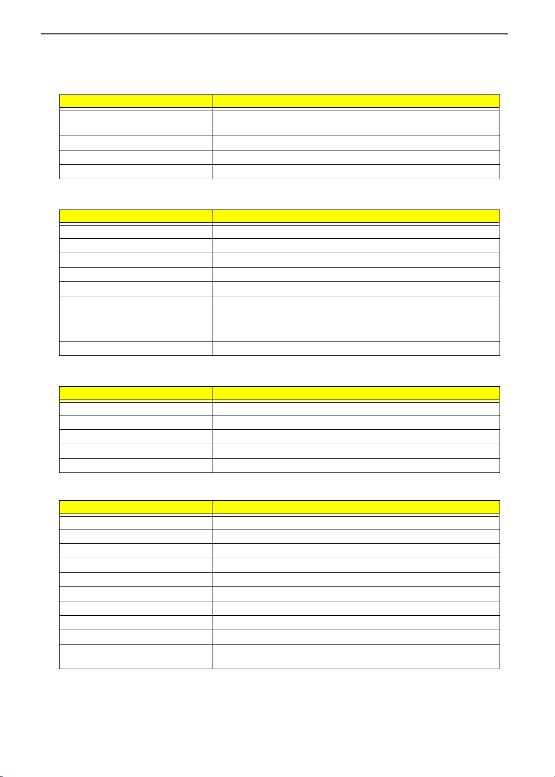
The following table describes the information in this screen.
Parameter Description
CPU Type Describes the type of CPU installed in the system
CPU Speed Describes the speed of CPU installed in this system
System Memory Display the current system memory
Extended Memory Display the current extended memory
HDD1 Serial Number Display the primary master HDD serial number. If there is no primary master
HDD, then show “None”
HDD 2 serial Number Display the secondary master HDD serial number. If there is no secondary
master HDD, then show “None”
System BIOS Version Shows the current system BIOS version.
VGA BIOS Version Shows the video graphics accelerator BIOS version
KBC Version The current KBC version
Serial Number Display the System Serial Number (32 Characters)
Asset Tag Number Display the Asset Tag Number (16 Characters)
Product Name Display the Product Name (15 Characters)
Manufacture Name Display the Manufacture Name (15 Characters)
UUID Display the UUID (16 Byte Hex-Digital)
LAN Device Shows the status of LAN device. Displays the MAC address of LAN device
existed. If the device does not exist, this entry should be invisible.
The items in this screen are important and vital information about your computer. If you experience computer
problems and need to contact technical support, this data helps our service personnel know more about your
computer.
Basic System Settings
The Basic System Settings screen allows you to set the system date and time.
PhoenixBIOS Setup Utility
PhoenixBIOS Setup Utility
Information Main Advanced Security Boot Exit
Information Main Advanced Security Boot Exit
Item Specific Help
System Time: [15:38:18]
System Time: [15:38:18]
System Date: [08/13/2002]
System Date: [08/13/2002]
Boot Display [Both]
Boot Display [Both]
Screen Expansion [Enabled]
Screen Expansion [Enabled]
QuickBoot Mode [Enabled]
QuickBoot Mode [Enabled]
Startup Screen [Disabled]
Startup Screen [Disabled]
Boot on LAN [Disabled]
Boot on LAN [Disabled]
Hotkey Beep [Enabled]
Hotkey Beep [Enabled]
Auto Dim [Enabled]
Auto Dim [Enabled]
F12 Multi-Boot [Enabled]
F12 Multi-Boot [Enabled]
Item Specific Help
<Tab>, <Shift-Tab>, or
<Tab>, <Shift-Tab>, or
<Enter> slects field.
<Enter> slects field.
F1 Help ÏÐ Select Item F5/F6 Change Values F9 Setup Defaults
F1 Help ÏÐ Select Item F5/F6 Change Values F9 Setup Defaults
Esc Exit ÍÎ Select Menu Enter Select Sub-Menu F10 Save and Exit
Esc Exit ÍÎ Select Menu Enter Select Sub-Menu F10 Save and Exit
¡¿
¡¿
29
Page 38

The following table describes the parameters in this screen.
Parameter Description Options
System Time Sets the system time.
HH:MM:SS (hour:minute:second)
Help: <Tab>, <Shift-Tab>, or
<Enter> Selects field.
System Date Sets the system date.
DDD MMM DD, YYYY
(day-of-the-week month day, year)
Help: <Tab>, <Shift-Tab>, or
<Enter> Selects field.
Boot Display Set the display output device on
boot up
When set to Auto, the computer is
automatically determines the
display device. if an external display
device (e.g., monitor) is connected,
it becomes the boot display.
When set to Both, the computer
outputs to both the LCD and the
external display if one is connected.
Screen Expansion Help: Options: Enable or Disable Enabled or Disabled
QuickBoot Mode Allow the system to skip certain
tests while booting. This will
decrease the time needed to boot
the system.
Startup Screen When set to disabled, system will
show the graphic picture screen on
boot up.
Boot on LAN When set to enabled, the system
will boot from on LAN.
Notice: Need to restart the system
to enable Boot-on-LAN function.
Hotkey Beep Enable or disable hotkey beep. Enabled or Disabled
Auto Dim The system will support an
automatic dimming of the LCD
F12 Multi-Boot Users could choose if “Fn-F12 for
multi-boot” message is to be
displayed during post.
Both or Auto
Enabled or Disabled
Disabled or Enabled
Disabled or Enabled
Enabled or Disabled
Enabled or Disabled
TECHNICAL SERVICE MANUALPrestigio Signore 152
30
Page 39

TECHNICAL SERVICE MANUAL Prestigio Signore 152
Startup Configuration
The Startup Configuration screen contains parameter values that define how your computer behaves on
system startup.
PhoenixBIOS Setup Utility
PhoenixBIOS Setup Utility
Information Main Advanced Security Boot Exit
Information Main Advanced Security Boot Exit
Item Specific Help
Legacy Disk A:: [1.44/1.25 MB 3½” ]
Legacy Disk A:: [1.44/1.25 MB 3½” ]
Primary Master [TOSHIBA MK3018GAP]
Primary Master [TOSHIBA MK3018GAP]
Secondary Master [UJDA360-(SM)]
Secondary Master [UJDA360-(SM)]
Onboard Device Configuration
Onboard Device Configuration
Wake on LAN from S5 [Disabled]
Wake on LAN from S5 [Disabled]
Reset Configuration Data [No]
Reset Configuration Data [No]
CPU Power Management Mode [Auto]
CPU Power Management Mode [Auto]
Battery Refresh
Battery Refresh
Item Specific Help
Selects floppy type. Note
Selects floppy type. Note
that 1.25 MB 3½” floppy
that 1.25 MB 3½” floppy
refers to a 1024 byte/sector
refers to a 1024 byte/sector
Japanese media format.
Japanese media format.
The1.25 MB, 3½” diskette
The1.25 MB, 3½” diskette
requires a 3-Mode
requires a 3-Mode
floppy-disk drive/
floppy-disk drive/
F1 Help ÏÐ Select Item F5/F6 Change Values F9 Setup Defaults
F1 Help ÏÐ Select Item F5/F6 Change Values F9 Setup Defaults
Esc Exit ÍÎ Select Menu Enter Select Sub-Menu F10 Save and Exit
Esc Exit ÍÎ Select Menu Enter Select Sub-Menu F10 Save and Exit
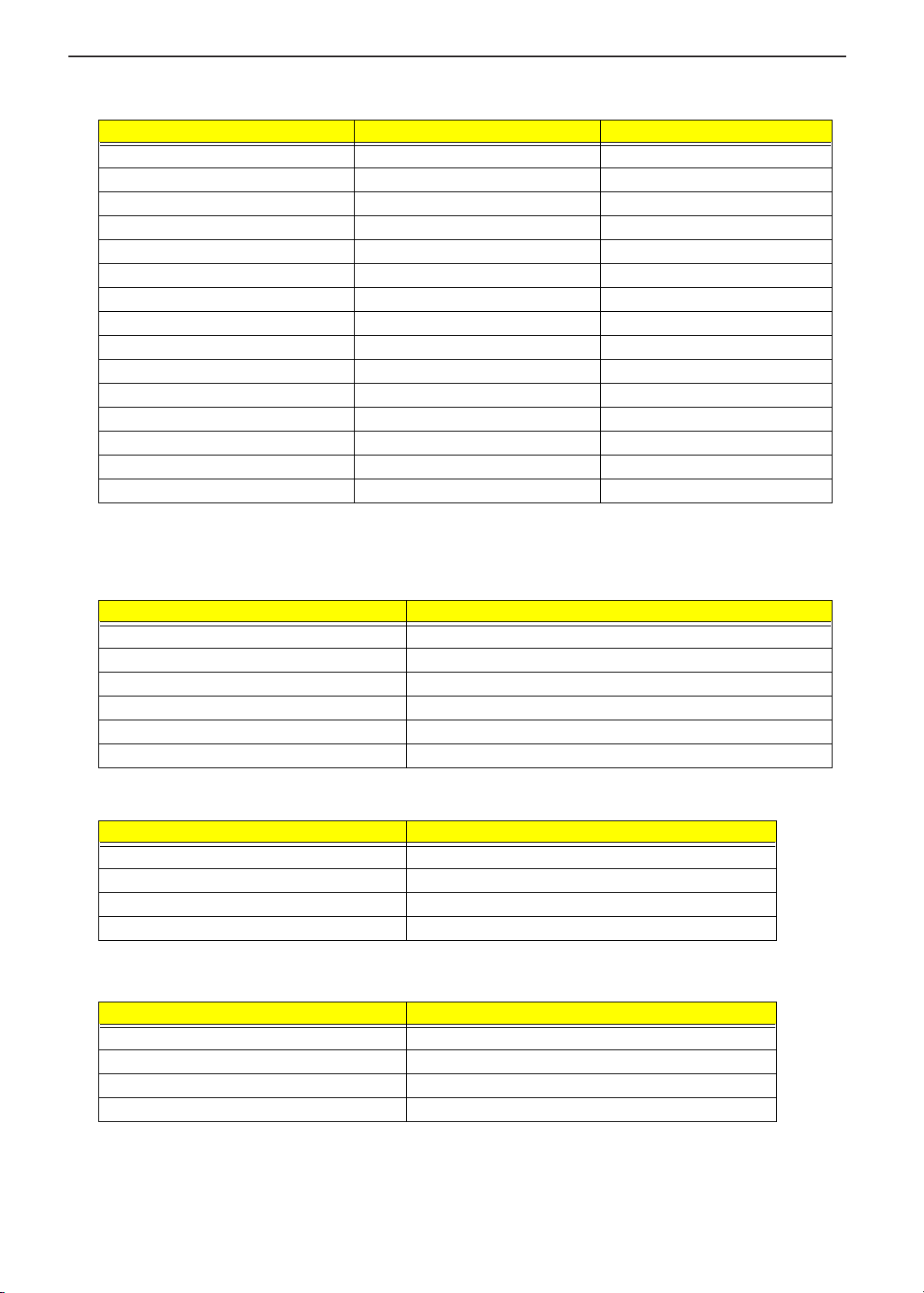
The following table describes the parameters in this screen. Settings in boldface are the default and
suggested parameter settings.
Parameter Description Options
Legacy Diskette A Enable or Disable Legacy Diskette A. 1.44/1.25MB 31/2 or
Primary Master Show IDE Primary Master HDD size.
User can enter sub-menu to set some detail
functions.
Secondary Master Show IDE Secondary Master Device Status.
User can enter sub-menu to set some detail
functions.
OnBoard Device Configuration Enter sub-menu to set onboard device configuration
Help: Peripheral Configuration
Disabled: No configuration
Enabled: User Configuration
Serial port: Enabled
Parallel port: Enabled
Wake on LAN from S5 Set Enabled or Disabled to wake on LAN access. Disabled or Auto
Reset Configuration Data Select “Yes” if you want to clear the Extended System
Configuration Data (ESCD) area.
CPU Power Management Mode If the setting is Auto, then do the CPU stop clock
state. If the setting is Disabled, then do the CPU stop
grant state, and FAN always on.
Battery Refresh Select for battery refresh function.
¡¿
¡¿
disabled
Auto, User, CD-ROM,
ATAPI Removable
Auto, User, CD-ROM,
ATAPI Removable
Enabled or Disabled
No or Yes
Disabled or Auto
31
Page 40

TECHNICAL SERVICE MANUALPrestigio Signore 152
Primary Master
The Primary Master sub-menu contains parameter related to the primary hard disk.
CAUTION: The parameters in this screen are for advanced users only. Typically you do not need to change
the values in this screen. The default setting of Auto optimizes all the setting for your hard disk.
PhoenixBIOS Setup Utility
PhoenixBIOS Setup Utility
Advanced
Advanced
Primary Master [TOSHIBA MK3018GAP-(PM)]
Primary Master [TOSHIBA MK3018GAP-(PM)]
Type: [Auto]
Type: [Auto]
Multi-Sector Transfers: [16 Sectors]
Multi-Sector Transfers: [16 Sectors]
LBA Mode Control: [Enabled]
LBA Mode Control: [Enabled]
32 Bit I/O: [Disabled]
32 Bit I/O: [Disabled]
Transfer Mode: [Fast PIO 4]
Transfer Mode: [Fast PIO 4]
Ultra DMA Mode: [Disabled]
Ultra DMA Mode: [Disabled]
F1 Help ÏÐ Select Item F5/F6 Change Values F9 Setup Defaults
F1 Help ÏÐ Select Item F5/F6 Change Values F9 Setup Defaults
ÍÎ
Esc Exit
Esc Exit
Parameter Description Options
Type The setting of detail functions stands on type. Auto, User, CD-ROM, ATAPI
ÍÎ
Select Menu Enter Select Sub-Menu F10 Save and Exit
Select Menu Enter Select Sub-Menu F10 Save and Exit
¡¿
¡¿
Item Specific H elp
Item Specific H elp
User= you enter parameters of
User= you enter parameters of
Hard-disk drive installed at this
Hard-disk drive installed at this
Connection.
Connection.
Auto= autotypes hard-disk
Auto= autotypes hard-disk
drive installed here.
drive installed here.
CD-ROM = a CD-ROM drive is
CD-ROM = a CD-ROM drive is
Installed here.
Installed here.
ATAPI Removable= removable
ATAPI Removable= removable
disk drive is installed here.
disk drive is installed here.
Removable
32
Page 41

TECHNICAL SERVICE MANUAL Prestigio Signore 152
Secondary Master
The Secondary Master sub-menu contains parameters related to the Media bay drive.
CAUTION: The parameters in this screen are for advanced users only. Typically you do not need to change
the values in this screen. The default setting of Auto optimizes all the setting for your hard disk.
PhoenixBIOS Setup Utility
PhoenixBIOS Setup Utility
Advanced
Advanced
Secondary Master [UJDA360-(SM)]
Secondary Master [UJDA360-(SM)]
Type: [Auto]
Type: [Auto]
Multi-Sector Transfers: [Disabled]
Multi-Sector Transfers: [Disabled]
LBA Mode Control: [Disabled]
LBA Mode Control: [Disabled]
32 Bit I/O: [Disabled]
32 Bit I/O: [Disabled]
Transfer Mode: [Standard]
Transfer Mode: [Standard]
Ultra DMA Mode: [Disabled]
Ultra DMA Mode: [Disabled]
F1 Help ÏÐ Select Item F5/F6 Change Values F9 Setup Defaults
F1 Help ÏÐ Select Item F5/F6 Change Values F9 Setup Defaults
Esc Exit ÍÎ Select Menu Enter Select Sub-Menu F10 Save and Exit
Esc Exit ÍÎ Select Menu Enter Select Sub-Menu F10 Save and Exit
Parameter Description Options
Type The setting of detail functions stands on type. Auto, User, CD-ROM, ATAPI
¡¿
¡¿
Item Specific Help
Item Specific Help
User= you enter parameters of
User= you enter parameters of
Hard-disk drive installed at this
Hard-disk drive installed at this
Connection.
Connection.
Auto= autotypes hard-disk
Auto= autotypes hard-disk
drive installed here.
drive installed here.
CD-ROM= a CD-ROM drive is
CD-ROM= a CD-ROM drive is
Installed here.
Installed here.
ATAPI Removable= removable
ATAPI Removable= removable
disk drive is installed here.
disk drive is installed here.
Removable
33
Page 42

TECHNICAL SERVICE MANUALPrestigio Signore 152
OnBoard Device Configuration
The parameters in this screen are for advanced users only. You do not need to change the values in this
screen because these values are already optimized.
The Onboard Device Configuration screen assigns resources to basic computer communication hardware.
PhoenixBIOS Setup Utility
PhoenixBIOS Setup Utility
Advanced
Advanced
OnBoard Device Configuration
OnBoard Device Configuration
Serial port [Enabled]
Serial port [Enabled]
Base I/O address: [3F8]
Base I/O address: [3F8]
Interrupt: [IRQ4]
Interrupt: [IRQ4]
Parallel port: [Enabled]
Parallel port: [Enabled]
Mode: [ECP]
Mode: [ECP]
Base I/O address: [378]
Base I/O address: [378]
Interrupt: [IRQ7]
Interrupt: [IRQ7]
DMA channel: [DMA3]
DMA channel: [DMA3]
F1 Help ÏÐ Select Item F5/F6 Change Values F9 Setup Defaults
F1 Help ÏÐ Select Item F5/F6 Change Values F9 Setup Defaults
Esc Exit ÍÎ Select Menu Enter Select Sub-Menu F10 Save and Exit
Esc Exit ÍÎ Select Menu Enter Select Sub-Menu F10 Save and Exit
The following table describes the parameters in this screen. Settings in boldface are the default and
suggested parameter settings.
Parameter Description Options
Serial Port Enables or disables the serial port.
The serial port is a PnP device. Enabled/Disabled
setting won’t affect the Windows Device Manager
setting of the serial port.
¡¿
¡¿
Item Specific Help
Item Specific Help
Configure serial port using
Configure serial port using
options:
options:
[Disabled]
[Disabled]
No configuration
No configuration
[Enabled]
[Enabled]
User configuration
User configuration
Enabled or Disabled
Base I/O address: Set the base I/O address of the
serial port.
Help: Set the I/O address for the serial port A.
Interrupt: Set the IRQ of the serial port.
Help: Set the IRQ for the serial port A.
34
3F8, 2F8, 3E8 or 2E8
4 or 3
Page 43

TECHNICAL SERVICE MANUAL Prestigio Signore 152
Parameter Description Options
Parallel Port Enables or disable the parallel port.
The parallel port is a PnP device. Enabled/Disabled
setting won’t affect the Windows Device Manager
setting of the parallel port.
Help: [Enabled]=User Configuration
[Disabled]=No Configuration
Enabled or Disabled
1 or 3
Mode: Set the mode for the parallel port using options.
If operation mode is set to ECP DMA Channel, sets
the direct memory access (DMA) channel for the
printer to operate in ECP mode. This parameter is
enabled only if operation mode is set to ECP.
Base I/O address: If operation mode is set to Base I/O
address, sets the base I/O address of the parallel port.
Interrupt: If operation mode is set to interrupt, sets the
interrupt request of the parallel port.
DMA Channel: Set a DMA channel for the printer to
operate in ECP mode. This parameter is enabled only
if the operation mode is set to ECP. Sets the DMA
channel for the parallel port.
ECP, Bi-directional, EPP, or
Output only
378, 3BC, or 278
7 or 5
DMA 3 or DMA 1
System Security
The System Security screen contains parameters that help safeguard and protect your computer from
unauthorized use.
PhoenixBIOS Setup Utility
PhoenixBIOS Setup Utility
Information Main Advanced Security Boot Exit
Information Main Advanced Security Boot Exit
Item Specific Help
Item Specific Help
Set Supervisor Password [Enter]
Set Supervisor Password [Enter]
Set User Password [Enter]
Set User Password [Enter]
Password on boot: [Disabled]
Password on boot: [Disabled]
Supervisor Password controls
Supervisor Password controls
Set Primary Hard Disk Password [Enter]
Set Primary Hard Disk Password [Enter]
F1 Help ÏÐ Select Item F5/F6 Change Values F9 Setup Defaults
F1 Help ÏÐ Select Item F5/F6 Change Values F9 Setup Defaults
Esc Exit ÍÎ Select Menu Enter Select Sub-Menu F10 Save and Exit
Esc Exit ÍÎ Select Menu Enter Select Sub-Menu F10 Save and Exit
The following table describes the parameters in this screen. Settings in boldface are the default and
suggested parameter settings.
¡¿
¡¿
access to the setup utility.
access to the setup utility.
35
Page 44

Parameter Description Options
Set Supervisor Password While entering SETUP, BIOS need to request user to enter
supervisor password if set.
This password protects the BIOS SETUP menu from
unauthorized entry.
Set User Password During POST, BIOS need to check user password if set.
This password protects the system from unauthorized user
entry before OS boots up.
Password on boot During POST, BIOS need to check hard disk password if set.
This password protects the computer from unauthorized entry
during boot-up.
Set Primary Hard Disk
Password
Input HDD Password. When set, this password protects the
hard disk from unauthorized access. See the following section
for instructions on how to set a password.
Setting a Password
Follow these steps:
1. Use the cursor
Password on boot or Primary Hard Disk Password) and press the
as below if choosing Set Supervisor Password:
keys to highlight a Password parameter (Supervisor Password, User Password,
w/y
TECHNICAL SERVICE MANUALPrestigio Signore 152
Enter
Enter
Disabled
Enter
key. The password box appears
e
Set Supervisor Password
Set Supervisor Password
Ente r N e w Passwo rd [ ]
Ente r N e w Passwo rd [ ]
Con firm N ew P assword [ ]
Con firm N ew P assword [ ]
2. Type a password. The password may consist of up to eight characters (A-Z, a-z, 0-9) and then press
.
e
IMPORTANT:Be very careful when typing your password because the characters do not appear on the
screen.
3. Retype password to verify your first entry and then press
Setup Notice
Setup Notice
Changes have been saved.
Changes have been saved.
[Continue]
[Continue]
4. After setting the password, the computer automatically sets the chosen password parameter to Present.
5. Press
6. Press
to return to the main menu.
^
. The following dialogue box appears.
^
. The following screen appears:
e
36
Page 45

TECHNICAL SERVICE MANUAL Prestigio Signore 152
Setup Confirmation
Setup Confirmation
Save Configuration changes and exit now?
Save Configuration changes and exit now?
[Yes] [No]
[Yes] [No]
7. Select Yes and press
Four password types protect your computer from unauthorized access. Setting these passwords creates
several different levels of protection for your computer and data:
Supervisor Password prevents unauthorized entry to the BIOS Utility. Once set, you must key-in
T
this password to gain access to the BIOS Utility.
User Password and Password On Boot secure your computer against unauthorized use. Combine
T
the use of this password with password checkpoints on boot-up and resume from hibernation for
maximum security.
Hard Disk Password protects your data by preventing unauthorized access to your hard disk.
T
Even if the hard disk is removed from the computer and moved to another computer, it cannot be
accessed without the Hard Disk Password.
When a password is set, a password prompt appears on the left-hand corner of the display screen.
1. When the Supervisor Password is set, the following prompt appears when you press
BIOS Utility at boot-up.
to save the password and exit the BIOS utility.
e
to enter the
m
Enter Password
Type the Supervisor Password and press
2. When the User Password is set and Power on boot is set enabled, the following prompt appears at bootup when pressing
m
.
to access the BIOS Utility.
e
Enter Password
Type the User Password (a symbol appears for each character you type) and press
If you enter the password incorrectly, an x symbol appears. Try again and press
3. When the Power on boot is set enabled, the following prompt appears at boot-up.
e
e
Enter Password
4. When the Hard Disk Password is set, the following prompt appears at boot-up.
37
to use the computer.
.
Page 46

Enter Password
TECHNICAL SERVICE MANUALPrestigio Signore 152
Type the Hard Disk Password (a symbol appears for each character you type) and press
computer. If you enter the password incorrectly, an x symbol appears. Try again and press
You have three chances to enter a password. If you successfully entered the password, the system starts
Windows.
Removing a Password
If you fail to enter the password correctly after three tries, the system hangs.
To change a password, follow the same steps used to set a password.
1. Use the cursor
Password on boot ) and press
keys to highlight a Password parameter (Supervisor Password, User Password,
w/y
. The following prompt appears:
e
e
e
to use the
.
Enter Current Password [ ]
Enter New Password [ ]
Confi r m New Password [ ]
2. Type Current Password, leave the “ Enter New Password” blank, and then type “ Confirm New Password”.
Press
Removing a HDD Password
If you fail to enter a HDD password correctly after three tries, the system will be disabled.
To change a password, follow the same steps used to set a password.
1. After three tries, a prompt appears: (for example, if the primary master HDD is locked.)
, the password is removed.
e
Enter Primary Master HDD Master Password [ ]
2. Enter the BIOS utility to check HDD’s serial number and write it down.
3. Use another computer to generate the HDD Password with hddmas.exe or mashdd2.exe . Type the
HDD’s serial number, press
4. Type the generated HDD password in the following prompt you set up.
, HDD password will be generated.
e
Enter Primary Master HDD Master Password [ ]
38
Page 47

TECHNICAL SERVICE MANUAL Prestigio Signore 152
5. Press
, the previous HDD password you set up will be overwritten.
e
Boot Options
Users can press F12 during POST to enter the Boot Options Menu. In this menu users can change boot
device without entering BIOS SETUP utility.
PhoenixBIOS Setup Utility
PhoenixBIOS Setup Utility
Boot
Information Main Advanced Security
Information Main Advanced Security
1. CD-ROM Drive
1. CD-ROM Drive
2. +Removable Devices
2. +Removable Devices
3. +Hard Drive
3. +Hard Drive
4. Network Boot
4. Network Boot
Keys used to view or configure
Keys used to view or configure
devices:
devices:
<Enter> expands or collapses
<Enter> expands or collapses
devices with a + or - <F6> and
devices with a + or - <F6> and
<F5> moves the device up or
<F5> moves the device up or
down.
down.
Boot
Item Specific Help
Item Specific Help
Exit
Exit
F1 Help ÏÐ Select Item F5/F6 Change Values F9 Setup Defaults
F1 Help ÏÐ Select Item F5/F6 Change Values F9 Setup Defaults
Esc Exit ÍÎ Select Menu Enter Select Sub-Menu F10 Save and Exit
Esc Exit ÍÎ Select Menu Enter Select Sub-Menu F10 Save and Exit
NOTE: There are four priorities that can let the user to specify the boot device sequence.
The priority of options from top to bottom is 1
If the Removable Device or Hard Drive option has multi devices, show ‘+’ in front of option and show each
device information.
If secondary Hard Disk exists, user can also choose it to Boot. If secondary hard Disk is nonexistence, hide the
secondary Hard Disk option.
Help: Keys used to view or configure devices:
<
> expands or collapses devices with a + or -
e
<
>and <q> moves the device up and or down.
p
st
, 2nd, 3rd, 4th.
¡¿
¡¿
39
Page 48

Exit Setup
This menu contains exit options.
Information Main Advanced Security Boot Exit
Information Main Advanced Security Boot Exit
Exit Saving Changes
Exit Saving Changes
Exit Discarding Changes
Exit Discarding Changes
Load Setup Defaults
Load Setup Defaults
Discard Changes
Discard Changes
Save Changes
Save Changes
F1 Help ÏÐ Select Item F5/F6 Change Values F9 Setup Defaults
F1 Help ÏÐ Select Item F5/F6 Change Values F9 Setup Defaults
Esc Exit ÍÎ Select Menu Enter Select Sub-Menu F10 Save and Exit
Esc Exit ÍÎ Select Menu Enter Select Sub-Menu F10 Save and Exit
PhoenixBIOS Setup Utility
PhoenixBIOS Setup Utility
Item Specific Help
Item Specific Help
Exit System Setup and save your
Exit System Setup and save your
Changes to CMOS
Changes to CMOS
¡¿
¡¿
TECHNICAL SERVICE MANUALPrestigio Signore 152
The following table describes the parameters in this screen. Setting in boldface are the defaults and
suggested parameter settings.
Parameter Description
Exit Saving Changes Save any changes, and exit BIOS setup.
Help: Exit System Setup and save your changes to CMOS.
Exit Discarding Changes Discard any changes, and exit BIOS setup.
Help: Exit utility without saving Setup data to CMOS.
Load Setup Defaults Load Setup Defaults.
Help: Load default values for all SETUP items.
Discard Changes Discard any changes.
Help: Load previous value from CMOS for all SETUP items.
Save Changes Save changes.
Help: Save Setup data to CMOS.
Load Default Settings
If you want to restore all parameter settings to their default values, select this menu item and press
following dialog box displays.
e
. The
If you would like to load factory- default settings for all parameters, use the cursor
then press
. Choose No if otherwise.
e
40
z
/
keys to select Yes;
x
Page 49

TECHNICAL SERVICE MANUAL Prestigio Signore 152
BIOS Flash Utility
The BIOS flash memory update is required for the following conditions:
New versions of system programs
T
New features or options
T
Use the Phlash utility to update the system BIOS flash ROM.
NOTE: Do not install memory-related drivers (XMS, EMS, DPMI) when you use Phlash.
NOTE: This program contains a readme.txt file. This readme.txt file will introduce on how to use Phlash utility.
41
Page 50

TECHNICAL SERVICE MANUALPrestigio Signore 152
System Utility Diskette
This utility diskette is for the OpenBook 1846 notebook machine. You can find the utility in Service CD kit. It
provides the following functions:
1. Panel ID Utility
2. Thermal & Fan Utility
3. Mother Board Data Utility
To use this diskette, first boot from this diskette, then a “Microsoft Windows ME Startup Menu” prompt you to
choose the testing item. Follow the instructions on screen to proceed.
NOTE: This program contains a readme.txt file. This readme.txt file will introduce each test utility and its
functions.
42
Page 51

TECHNICAL SERVICE MANUAL Prestigio Signore 152
System Diagnostic Diskette
1
IMPORTANT:
NOTE: This program contains a readme.txt file. This readme.txt file will introduce each test and its functions.
The diagnostics program here that we used is called PQA (Product Quality Assurance) and is
provided by Headquarters. You can utilize it as a basic diagnostic tool. To get this program, you can
find it in the service CD kit.
To better fit local service requirements, your regional office MAY have other diagnostic program.
Please contact your regional offices or the responsible personnel/channel to provide you with further
technical details.
1
New added description. Please pay attention to it.
43
Page 52

Running PQA Diagnostics Program
PQA Vx_x xx-xx-xx
TECHNICAL SERVICE MANUALPrestigio Signore 152
Result
SysInfo
Option
to enable the selected option. The main options
e
Exit
Press
z
Diag
/
to move around the main menu. Press
x
are Diag, Result, SysInfo, Option and Exit.
The Diag option lets you select testing items and times.
The following screen appears when you select Diag from the main menu.
PQA Vx_x xx-xx-xx
Diag
Result
Diag
ONE TEST
MULTI TEST
FULL TEST
QUICK TEST
SysInfo
Option
Exit
One Test performs a single test and Manual checks the selected test items in sequence.
Multi Test performs multiple tests of the selected items and check the selected test items in sequence.
Full Test performs all test items in detail for your system.
Quick Test performs all test items quickly for your system.
44
Page 53

TECHNICAL SERVICE MANUAL Prestigio Signore 152
The screen below appears if you select Multi Test.
PQA Vx_x xx-xx-xx
PQA Vx_x xx-xx-xx
Diag
Diag
Specify the desired number of tests and press
Result
Result
Diag
Diag
ONE TEST
One TEST
MULTI TEST
Multi TEST
FULL TEST
QUICK TEST
TEST COUNT VALUE (1...9999) 1
SysInfo
SysInfo
e
.
Option
Option
Exit
Exit
After you specify the number of tests to perform, the screen shows a list of test items (see below).
PQA Vx_x xx-xx-xx
Diag Result
Diag
Test Items
MANUAL TEST
[ ] System Board
AUTO TEST
[ ] Memory
[ ] Keyboard
[ ] Video
[ ] Parallel Port
[ ] Serial Port
[ ] Diskette Drive
[ ] Hard Disk
[ ] CD-ROM
[ ] Coprocessor
[ ] Pointing Dev.
[ ] Cache
SysInfo
Option
SPACE: mark/unmark selecting item
ESC : return to upper menu
F1 : Help menu
F2 : test the marked item(s)
ENTER: open sub-item’s menu
Test Ti mes = 1
Exit
Move the highlight bar from one item to another. Press Space to enable or disable the item. Press
view the available options of each selected item. Press
to close the submenu.
|
e
to
The right corner screen information gives you the available function keys and the specified test number.
T k
T ^
T l
T m
T e
T
NOTE: The
: Enables/disables the item
: Exits the program
: Help
: Tests the selected item(s)
: Opens the available options
Test Times: Indicates the number of tests to perform.
and m keys function only after you finish configuring the Test option.
l
NOTE: When any errors are detected by diagnostic program, refer to “Index of PQA Diagnostic Error Code” for
troubleshooting.
45
Page 54

TECHNICAL SERVICE MANUALPrestigio Signore 152
46
Page 55

TECHNICAL SERVICE MANUAL Prestigio Signore 152
Chapter 3
Machine Disassembly and Replacement
This chapter contains step-by-step procedures on how to disassemble the notebook computer for
maintenance and troubleshooting.
To disassemble the computer, you need the following tools:
Wrist grounding strap and conductive mat to prevent electrostatic discharge
T
Flat-bladed screwdriver
T
Phillips screwdriver
T
Hexagonal screwdriver
T
Plastic stick
T
A2 screwdriver
T
NOTE: The screws for the different components vary in size. During the disassembly process, group the
screws with the corresponding components to avoid mismatches when putting back the components.
47
Page 56

General Information
Before You Begin
Before proceeding with the disassembly procedure, make sure that you do the following:
1. Turn off the power to the system and all peripherals.
2. Unplug the AC adapter and all power and signal cables from the system.
TECHNICAL SERVICE MANUALPrestigio Signore 152
48
Page 57

TECHNICAL SERVICE MANUAL Prestigio Signore 152
Disassembly Procedure Flowchart
The flowchart on the succeeding page gives you a graphical representation on the entire disassembly
sequence and instructs you on the components that need to be removed during servicing. For example, if you
want to remove the system board, you must first remove the keyboard, then disassemble the inside assembly
frame in that order.
START
START
Battery
Battery
Hx1
Modem
Modem
Cover
Cover
Modem
Modem
Board
Board
CPU
CPU
PCMCIA
PCMCIA
Socket
Socket
I/O Port
I/O Port
Chassis
Chassis
Hx1
Ax2Ax2
Ax2Ax2
Ax2
Ax2
Ax4
Ax4
DVD-RW
DVD-RW
Dri ve W/
Dri ve W/
Transfer
Transfer
Board
Board
DVD-RW
DVD-RW
Transfer
Transfer
Board
Board
DVD-RW
DVD-RW
Module
Module
Ax2
Ax2
Bx4
Bx4
HDD
HDD
Module
Module
DVD-RW
DVD-RW
Chassis
Chassis
Dx4
Dx4
HDD
HDD
HDD
HDD
Bracket
Bracket
Touch Pad
Touch Pad
Scroll Key
Scroll Key
DIMM Cover
DIMM Cover
Touch Pad
Touch Pad
Frame W/
Frame W/
Touch Pad
Touch Pad
Button
Button
Touch Pad
Touch Pad
DIMM
DIMM
Board
Board
Hx1
Hx1
Bx4
Bx4
Cx3
Cx3
LCD Module
LCD Module
(See Next
(See Next
Page)
Page)
Ax2
Ax2
Speakers
Speakers
Keyboard
Keyboard
Upper Case
Upper Case
FDD
FDD
Bracket
Bracket
Ax3
Ax3
Ax1
Ax1
Cx2
Cx2
DC Charger
DC Charger
RTC Bat ter y
RTC Bat ter y
AX1
AX1
Cx2
Cx2
Bx14
Bx14
Cx1
Cx1
FDD Module
FDD Module
Launch Board
Launch Board
Plate
Plate
Cx3
Cx3
Gx2
Gx2
FDD
FDD
Middle
Middle
Cover W/
Cover W/
Keyboard
Keyboard
Support
Support
Bracket
Bracket
DC to DC
DC to DC
Board
Board
Launch
Launch
Ex4
Ex4
CPU Fan
CPU Fan
Sink
Sink
Thermal
Thermal
Plate
Plate
Mai n
Mai n
Board
Board
Lower Case
Lower Case
Board
Board
Cx4
Cx4
Ax2
Ax2
Ax2
Ax2
Fx6
Fx6
Ax1
Ax1
49
Page 58

LCD
LCD
Module
Module
LCD
LCD
Bezel
Bezel
Bx5
Bx5
TECHNICAL SERVICE MANUALPrestigio Signore 152
Bx4
Bx4
LCD
LCD
Hinges
Hinges
LCD
LCD
Coaxial
Coaxial
Cable
Cable
Screw List
Item Description
A SCREW M2*L4 (Silver)
B SCREW M2.5XL6 (Black)
C SCREW M2XL5 (Silver)
D SCREW M3XL4 (Silver)
E CPU FAN SINK SCREW M2.5XL18 (Silver)
F SCREW HEX I#R-40/0#4-40 L5.5 (Silver)
G SCREW M2.5XL3 (Silver)
H SCREW M2XL3 (Black)
Inv erter
Inv erter
Board
Board
Bx1
Bx1
Ax6
Ax6
LCD
LCD
Panel
Panel
LCD Latch
LCD Latch
W/ Spring
W/ Spring
50
Page 59

TECHNICAL SERVICE MANUAL Prestigio Signore 152
Removing the Battery Pack
1. To remove the battery pack, first push the secure latch and release the battery latch.
2. Release the other two latches and lift the battery pack up at the same time.
3. Detach the battery pack from the machine.
51
Page 60

TECHNICAL SERVICE MANUALPrestigio Signore 152
Removing the Extended Memory
1. See “Removing the Battery Pack” on page 51
2. To remove the extended memory, first loosen the screw as shown and then lift the extended memory
cover upward.
3. Detach the DIMM cover from the main unit.
4. Press the latches on both sides of the socket and pull the memory module out from the machine.
52
Page 61

TECHNICAL SERVICE MANUAL Prestigio Signore 152
Removing the Modem Board
1. See “Removing the Battery Pack” on page 51
2. To remove the modem board from the machine, first release the screw from the modem cover.
3. Remove the two screws as shown here.
4. Lift the modem and turn it over carefully. Disconnect the modem cable from the modem then remove it
from the system.
53
Page 62

TECHNICAL SERVICE MANUALPrestigio Signore 152
Removing the CD-RW Drive Module
1. See “Removing the Battery Pack” on page 51
2. Push the CD-RW latch forward, then slide the CD-RW drive out from the machine at the same time.
Disassembling the CD-RW Drive Module
1. See “Removing the Battery Pack” on page 51
2. See “Removing the CD-RW Drive Module” on page 54
3. Remove the four screws from both sides as shown here, then detach the bracket from the CD-RW drive.
4. Remove the two screws as shown, then detach the CD-RW bay transfer board from the CD-RW drive.
54
Page 63

TECHNICAL SERVICE MANUAL Prestigio Signore 152
Removing the Hard Disk Drive Module
1. See “Removing the Battery Pack” on page 51
2. See “Removing the CD-RW Drive Module” on page 54
3. Remove the four screws as shown here.
4. Pull the plastic tag out, then carefully remove the hard disk drive module from the machine.
Disassembling the Hard Disk Drive Module
1. See “Removing the Battery Pack” on page 51
2. See “Removing the CD-RW Drive Module” on page 54
3. See “Removing the Hard Disk Drive Module” on page 55
4. Remove the four screws as shown here, then slide the hard disk drive out from the bracket .
55
Page 64

TECHNICAL SERVICE MANUALPrestigio Signore 152
Disassembling the LCD
To avoid the risk of LCD damage, we suggest you to place a protective film on the LCD surface before
disassembly.
Removing the Middle Cover
1. See “Removing the Battery Pack” on page 51
2. To remove the middle cover, push up the middle cover gently from the main unit.
3. Pull the middle cover up and turn the middle cover over carefully, disconnect the launch cable from the
launch board to remove the middle cover.
4. Remove the two screws as shown and then remove the launch board from the middle cover.
Removing the Keyboard
1. See “Removing the Battery Pack” on page 51
2. See “Removing the Middle Cover” on page 56
56
Page 65

TECHNICAL SERVICE MANUAL Prestigio Signore 152
3. To remove the keyboard, first remove the three screws as shown here.
4. Lift the keyboard upward and then carefully place it on the upper case.
5. Disconnect the keyboard cable from the main board with a plastic flat screwdriver, then carefully remove
the keyboard from the main unit
Removing the LCD Module
1. See “Removing the Battery Pack” on page 51
2. See “Removing the Middle Cover” on page 56
3. See “Removing the Keyboard” on page 56
4. Disconnect the inverter cable from the main board.
57
Page 66

TECHNICAL SERVICE MANUALPrestigio Signore 152
5. Remove the screw and disconnect the LCD coaxial cable from the main board.
6. Remove four screws in front and two screws on the rear side to remove the LCD from the main unit.
Removing LCD Bezel
1. See “Removing the Battery Pack” on page 51
2. See “Removing the Middle Cover” on page 56
3. See “Removing the Keyboard” on page 56
4. See “Removing the LCD Module” on page 57
5. Remove five LCD plugs and then the five screws from the LCD bezel.
58
Page 67

TECHNICAL SERVICE MANUAL Prestigio Signore 152
6. Snap off the LCD bezel carefully then remove the LCD bezel from the module.
Removing the Inverter/LED Board
1. See “Removing the Battery Pack” on page 51
2. See “Removing the Middle Cover” on page 56
3. See “Removing the Keyboard” on page 56
4. See “Removing the LCD Module” on page 57
5. To remove the inverter board, remove the screw from the inverter.
6. Disconnect the power cable from the inverter.
7. Remove the inverter from the system.
Removing the LCD
1. See “Removing the Battery Pack” on page 51
2. See “Removing the Middle Cover” on page 56
3. See “Removing the Keyboard” on page 56
4. See “Removing the LCD Module” on page 57
5. See “Removing the Inverter/LED Board” on page 59
59
Page 68

6. Remove six screws from both sides of the LCD.
7. Then remove the LCD from the LCD panel.
TECHNICAL SERVICE MANUALPrestigio Signore 152
Removing the Coaxial Cable
1. See “Removing the Battery Pack” on page 51
2. See “Removing the Middle Cover” on page 56
3. See “Removing the Keyboard” on page 56
4. See “Removing the LCD Module” on page 57
5. See “Removing the Inverter/LED Board” on page 59
6. See “Removing the LCD” on page 59
7. Gently remove the ESD tape and disconnect the LCD coaxial cable from the LCD.
60
Page 69

TECHNICAL SERVICE MANUAL Prestigio Signore 152
Disassembling the Upper Case
1. See “Removing the Battery Pack” on page 51
2. See “Removing the Middle Cover” on page 56
3. See “Removing the Keyboard” on page 56
4. See “Removing the LCD Module” on page 57
5. See “Removing the Keyboard Support Bracket” on page 63
6. See “Removing the DC Charger Plate” on page 63
7. See “Removing the RTC Battery” on page 63
8. See “Removing the CPU Fan Sink” on page 64
9. To remove the upper case, first remove the two screws from the front side, and then remove the fifteen
screws from the rear side of the main unit.
10. Remove the touch pad cable from the connector carefully, and then detach the upper case from the lower
case.
61
Page 70

Removing the Touch Pad
1. See “Removing the Battery Pack” on page 51
2. See “Removing the Middle Cover” on page 56
3. See “Removing the Keyboard” on page 56
4. See “Removing the LCD Module” on page 57
5. See “Removing the Keyboard Support Bracket” on page 63
6. See “Removing the DC Charger Plate” on page 63
7. See “Removing the RTC Battery” on page 63
8. See “Disassembling the Upper Case” on page 61
9. Disconnect the touch pad cable from the main board and the touch pad board carefully.
TECHNICAL SERVICE MANUALPrestigio Signore 152
10. Release the latches as shown below and then snap off the touch pad frame together with the touch pad
button
11. Detach the scroll key and then remove the touch pad board from the upper case
62
Page 71

TECHNICAL SERVICE MANUAL Prestigio Signore 152
Disassembling the Lower Case
Removing the Keyboard Support Bracket
1. See “Removing the Battery Pack” on page 51
2. See “Removing the Middle Cover” on page 56
3. See “Removing the Keyboard” on page 56
4. First remove the screw as shown here.
5. And then remove the keyboard support bracket out from the main unit carefully.
Removing the DC Charger Plate
1. See “Removing the Battery Pack” on page 51
2. See “Removing the Middle Cover” on page 56
3. See “Removing the Keyboard” on page 56
4. See “Removing the Keyboard Support Bracket” on page 63
5. Remove the two screws as shown here, and then detach the DC-DC charger plate from the main board.
Removing the RTC Battery
1. See “Removing the Battery Pack” on page 51
2. See “Removing the Middle Cover” on page 56
3. See “Removing the Keyboard” on page 56
4. See “Removing the Keyboard Support Bracket” on page 63
5. See “Removing the DC Charger Plate” on page 63
63
Page 72

6. Remove the RTC Battery from the main board gently.
Removing the DC-DC Board
1. See “Removing the Battery Pack” on page 51
2. See “Removing the Middle Cover” on page 56
3. See “Removing the Keyboard” on page 56
4. See “Removing the Keyboard Support Bracket” on page 63
5. See “Removing the DC Charger Plate” on page 63
6. Detach the DC-DC board from the main board carefully.
TECHNICAL SERVICE MANUALPrestigio Signore 152
Removing the CPU Fan Sink
1. See “Removing the Battery Pack” on page 51
2. See “Removing the Middle Cover” on page 56
3. See “Removing the Keyboard” on page 56
4. See “Removing the Keyboard Support Bracket” on page 63
5. Remove the four screws as shown.
6. Disconnect the CPU fan sink cable, and then remove the CPU fan sink from the main board.
64
Page 73

TECHNICAL SERVICE MANUAL Prestigio Signore 152
Removing the CPU (Part I)
1. See “Removing the Battery Pack” on page 51
2. See “Removing the Middle Cover” on page 56
3. See “Removing the Keyboard” on page 56
4. See “Removing the Keyboard Support Bracket” on page 63
5. See “Removing the CPU Fan Sink” on page 64
6. Unsecure the latch as shown here.
7. Push the latch outward by using A2 screwdriver carefully.
8. Pull the CPU out from the socket carefully.
Installing the CPU (Part I)
1. Push the latch outward by using A2 screwdriver as shown here.
2. And then secure it well.
Removing the CPU (Part II)
1. See “Removing the Battery Pack” on page 51
2. See “Removing the Middle Cover” on page 56
3. See “Removing the Keyboard” on page 56
4. See “Removing the Keyboard Support Bracket” on page 63
5. See “Removing the CPU Fan Sink” on page 64
65
Page 74

TECHNICAL SERVICE MANUALPrestigio Signore 152
6. Release the latch, detach the CPU from its socket carefully and then put the latch back to its original
position.
Installing the CPU (Part II)
1. Release the latch and attach the CPU back to its socket. Please note that the triangle mark on the CPU
should align with the socket as shown below.
2. Secure the CPU well by putting the latch back to its original position.
Removing the Thermal Plate
1. See “Removing the Battery Pack” on page 51
2. See “Removing the Middle Cover” on page 56
3. See “Removing the Keyboard” on page 56
4. “Removing the Keyboard Support Bracket” on page 63
5. See “Removing the DC Charger Plate” on page 63
6. See “Removing the CPU Fan Sink” on page 64
7. Remove the four screws as shown here and then remove the thermal plate from the main board gently.
66
Page 75

TECHNICAL SERVICE MANUAL Prestigio Signore 152
Removing the Floppy Disk Drive Module
1. See “Removing the Battery Pack” on page 51
2. See “Removing the Middle Cover” on page 56
3. See “Removing the Keyboard” on page 56
4. See “Removing the Keyboard Support Bracket” on page 63
5. See “Removing the DC Charger Plate” on page 63
6. See “Removing the LCD Module” on page 57
7. See “Disassembling the Upper Case” on page 61
8. To remove the floppy disk drive module, first remove the screw.
9. Disconnect the floppy disk drive cable from the main board and remove it from the main unit carefully.
Disassembling the Floppy Disk Drive Module
1. See “Removing the Battery Pack” on page 51
2. See “Removing the Middle Cover” on page 56
3. See “Removing the Keyboard” on page 56
4. See “Removing the Keyboard Support Bracket” on page 63
5. See “Removing the DC Charger Plate” on page 63
6. See “Removing the LCD Module” on page 57
7. See “Disassembling the Upper Case” on page 61
8. See “Removing the Floppy Disk Drive Module” on page 67
67
Page 76

TECHNICAL SERVICE MANUALPrestigio Signore 152
9. To disassemble the floppy disk drive from the disk drive module, first remove the two screws as shown
here.
10. Detach the floppy disk from the floppy disk drive bracket and then tear off the floppy disk drive FPC cable
gently from the floppy disk drive.
Removing the Speakers
1. See “Removing the Battery Pack” on page 51
2. See “Removing the Middle Cover” on page 56
3. See “Removing the Keyboard” on page 56
4. See “Removing the Keyboard Support Bracket” on page 63
5. See “Removing the DC Charger Plate” on page 63
6. See “Removing the LCD Module” on page 57
7. See “Disassembling the Upper Case” on page 61
8. To remove the speakers, first disconnect the cable from the main board, and then remove the two screws
as shown.
9. Remove the speakers from the main board gently.
68
Page 77

TECHNICAL SERVICE MANUAL Prestigio Signore 152
Removing the Main Board
1. See “Removing the Battery Pack” on page 51
2. See “Removing the Middle Cover” on page 56
3. See “Removing the Keyboard” on page 56
4. See “Removing the Keyboard Support Bracket” on page 63
5. See “Removing the DC Charger Plate” on page 63
6. See “Removing the LCD Module” on page 57
7. See “Removing the CPU Fan Sink” on page 64
8. See “Disassembling the Upper Case” on page 61
9. See “Removing the Floppy Disk Drive Module” on page 67
10. See “Removing the Thermal Plate” on page 66
11. Disconnect the speaker cable from the main board. Remove the three screws as shown, then remove the
main board from the lower case gently.
69
Page 78

TECHNICAL SERVICE MANUALPrestigio Signore 152
Removing the PCMCIA
1. See “Removing the Battery Pack” on page 51
2. See “Removing the Middle Cover” on page 56
3. See “Removing the Keyboard” on page 56
4. See “Removing the Keyboard Support Bracket” on page 63
5. See “Removing the DC Charger Plate” on page 63
6. See “Removing the LCD Module” on page 57
7. See “Removing the CPU Fan Sink” on page 64
8. See “Disassembling the Upper Case” on page 61
9. See “Removing the Floppy Disk Drive Module” on page 67
10. See “Removing the Thermal Plate” on page 66
11. See “Removing the Main Board” on page 69
12. To remove the PCMCIA slot, first remove the four screws as shown, and then remove the PCMCIA slot
from the main board carefully.
Removing the I/O Port bracket
1. See “Removing the Battery Pack” on page 51
2. See “Removing the Middle Cover” on page 56
3. See “Removing the Keyboard” on page 56
4. See “Removing the Keyboard Support Bracket” on page 63
5. See “Removing the DC Charger Plate” on page 63
6. See “Removing the LCD Module” on page 57
7. See “Removing the CPU Fan Sink” on page 64
8. See “Disassembling the Upper Case” on page 61
9. See “Removing the Floppy Disk Drive Module” on page 67
10. See “Removing the Thermal Plate” on page 66
11. See “Removing the Main Board” on page 69
70
Page 79

TECHNICAL SERVICE MANUAL Prestigio Signore 152
12. Remove the three screws and then the other six hex screws.
13. Detach the main board from the I/O port bracket gently.
71
Page 80

TECHNICAL SERVICE MANUALPrestigio Signore 152
72
Page 81

TECHNICAL SERVICE MANUAL Prestigio Signore 152
Chapter 4
Troubleshooting
Use the following procedure as a guide for computer problems.
NOTE: The diagnostic tests are intended to test only our company’s products. Other brand’s products,
prototype cards, or modified options can give false errors and invalid system responses.
1. Obtain the failing symptoms in as much detail as possible.
2. Verify the symptoms by attempting to re-create the failure by running the diagnostic.
3. Test or by repeating the same operation.
4. Use the following table with the verified symptom to determine which page to go to.
Symptoms (Verified) Go To
Power failure. (The power indicator does not go on or
stay on.)
POST does not complete. No beep or error codes are
indicated.
POST detects an error and displayed messages on
screen.
The diagnostic test detected an error and displayed a
FRU code.
Other symptoms (i.e. LCD display problems or others). “Power-On Self-Test (POST) Error Message” on page
Symptoms cannot be re-created (intermittent problems). Use the customer-reported symptoms and go to “Power-
“Power System Check” on page 75.
“Power-On Self-Test (POST) Error Message” on page
80
“Undetermined Problems” on page 86
“Error Message List” on page 80
“System Diagnostic Diskette” on page 43
80
On Self-Test (POST) Error Message” on page 80
“Intermittent Problems” on page 86
“Undetermined Problems” on page 86
73
Page 82

TECHNICAL SERVICE MANUALPrestigio Signore 152
System Check Procedures
External Diskette Drive Check
Do the following to isolate the problem to a controller, driver, or diskette. A write-enabled, diagnostic diskette is
required.
NOTE: Make sure that the diskette does not have more than one label attached to it. Multiple labels can cause
damage to the drive or cause the drive to fail.
Do the following to select the test device. See “System Diagnostic Diskette” on page 43 for details.
1. Boot from the diagnostics diskette and start the PQA program (See “System Diagnostic Diskette” on page
43).
2. Go to the diagnostic Diskette Drive in the test items.
in the test items.
3. Press
4. Follow the instructions in the message window.
If an error occurs with the internal diskette drive, reconnect the diskette connector on the main board.
If the error still remains:
1. Reconnect the external diskette drive/CD-ROM module.
2. Replace the external diskette drive/CD-ROM module.
3. Replace the main board.
m
External CD/DVD-ROM Drive Check
Do the following to isolate the problem to a controller, drive, or CD/DVD-ROM. Make sure that the CD/DVDROM does not have any label attached to it. The label can cause damage to the drive or can cause the drive
to fail.
Do the following to select the test device:
1. Boot from the diagnostics diskette and start the PQA program (refer to “System Diagnostic Diskette” on
page 43.
2. Go to the diagnostic CD/DVD-ROM in the test items.
in the test items.
3. Press
4. Follow the instructions in the message window.
If an error occurs, reconnect the connector on the main board. If the error still remains:
1. Reconnect the external diskette drive/CD/DVD-ROM module.
2. Replace the external diskette drive/CD/DVD-ROM module.
3. Replace the main board.
m
Keyboard or Auxiliary Input Device Check
Remove the external keyboard if the internal keyboard is to be tested.
If the internal keyboard does not work or an unexpected character appears, make sure that the flexible cable
extending from the keyboard is correctly seated in the connector on the main board.
If the keyboard cable connection is correct, run the Keyboard Test. See “System Diagnostic Diskette” on page
43 for details.
If the tests detect a keyboard problem, do the following one at a time to correct the problem. Do not replace a
non-defective FRU:
1. Reconnect the keyboard cables.
2. Replace the keyboard.
3. Replace the main board.
74
Page 83

TECHNICAL SERVICE MANUAL Prestigio Signore 152
The following auxiliary input devices are supported by this computer:
Numeric keypad
T
External keyboard
T
If any of these devices do not work, reconnect the cable connector and repeat the failing operation.
Memory Check
Memory errors might stop system operations, show error messages on the screen, or hang the system.
1. Boot from the diagnostics diskette and start the PQA program (please refer to “System Diagnostic
Diskette” on page 43.
2. Go to the diagnostic memory in the test items.
3. Press
in the test items.
m
4. Follow the instructions in the message window.
NOTE: Make sure that the DIMM is fully installed into the connector. A loose connection can cause an error.
Power System Check
To verify the symptom of the problem, power on the computer using each of the following power sources:
1. Remove the battery pack.
2. Connect the power adapter and check that power is supplied.
3. Disconnect the power adapter and install the charged battery pack; then check that power is supplied by
the battery pack.
If you suspect a power problem, see the appropriate power supply check in the following list:
“Check the Power Adapter” on page 75
T
“Check the Battery Pack” on page 76
T
Check the Power Adapter
Unplug the power adapter cable from the computer and measure the output voltage at the plug of the power
adapter cable. See the following figure
Pin 1: +19 to +20.5V
Pin 2: 0V, Ground
1. If the voltage is not correct, replace the power adapter.
2. If the voltage is within the range, do the following:
Replace the main board.
T
If the problem is not corrected, see “Undetermined Problems” on page 86.
T
If the voltage is not correct, go to the next step.
T
NOTE: An audible noise from the power adapter does not always indicate a defect.
3. If the power-on indicator does not light up, check the power cord of the power adapter for correct
continuity and installation.
4. If the operational charge does not work, see “Check the Battery Pack” on page 76.
75
Page 84

TECHNICAL SERVICE MANUALPrestigio Signore 152
Check the Battery Pack
To check the battery pack, do the following:
From Software:
1. Check out the Power Management in control Panel
2. In Power Meter, confirm that if the parameters shown in the screen for Current Power Source and Total
Battery Power Remaining are correct.
3. Repeat the steps 1 and 2, for both battery and adapter.
4. This helps you identify first the problem is on recharging or discharging.
From Hardware:
1. Power off the computer.
2. Remove the battery pack and measure the voltage between battery terminals 1(+) and 6(ground). See the
following figure.
7
6
5
4
3
2
1
3. If the voltage is still less than 7.5 Vdc after recharging, replace the battery.
To check the battery charge operation, use a discharged battery pack or a battery pack that has less than 50%
of the total power remaining when installed in the computer.
If the battery status indicator does not light up, remove the battery pack and let it return to room temperature.
Re-install the battery pack.
If the charge indicator still does not light up, replace the battery pack. If the charge indicator still does not light
up, replace the DC/DC charger board.
Touchpad Check
If the touchpad doesn’t work, do the following actions one at a time to correct the problem. Do not replace a
non-defective FRU:
1. Reconnect the touchpad cables.
2. Replace the touchpad.
3. Replace the main board.
After you use the touchpad, the pointer drifts on the screen for a short time. This self-acting pointer movement
can occur when a slight, steady pressure is applied to the touchpad pointer. This symptom is not a hardware
problem. No service actions are necessary if the pointer movement stops in a short period of time.
76
Page 85

TECHNICAL SERVICE MANUAL Prestigio Signore 152
Phoenix BIOS Error Code Messages
The following are the list of messages that Phoenix BIOS can display. Most of them occur during POST. Some
of them display information about a hardware device, e.g., and the amount of memory installed. Others may
indicate a problem with a device, such as the way it has been configured. The following lists the explanation of
the messages and remedies for reported problems.
NOTE: If your system displays one of the messages marked below with an asterisk (*), write down the
message and contact your dealer. If your system change after you make changes in the Setup menus,
reset the computer, enter Setup and install Setup defaults or correct the error.
Error Codes Error Messages
0200 Failure Fixed Disk
Fixed disk is not working or not configured properly. Check to see if fixed disk is
attached properly. Run Setup. Find out if the fixed-disk type is correctly identified.
0210 Stuck key
Stuck key on keyboard
0211 Keyboard Error
Keyboard is not working
0212 *Keyboard Controller Failed
Keyboard controller failed test. May require replacing keyboard controller.
0213 Keyboard Locked - Unlock Key Switch
Unlock the system to proceed
0220 Monitor type does not match CMOS - Run Setup
Monitor type not correctly identified on Setup
*0230 Shadow RAM failed at offset: nnnn
Shadow RAM failed at offset nnnn of in the 64k block at which the error was detected.
*0231 System RAM failed at offset: nnnn
System RAM failed at offset nnnn of in the 64k block at which the error was detected.
*0232 Extended RAM failed at offset: nnnn
Extended memory not working or not configured properly at offset nnnn.
0250 System batt ery is dead - Replace and run setup
The CMOs clock battery indicator shows the battery is dead. Replace the battery and
run Setup to reconfigure the system.
0251 System CMOS checksum bd - Default configuration used
System CMOS has been corrupted or modified incorrectly, perhaps by an application
program that changes data stored in CMOS. The BIOS default installed Default Setup
Values. If you do not want these values, enter Set up and enter your own values. If the
error persists, check the system battery or contact your dealer.
*0260 System Time Error
The timer test failed. Requires repair of system board
*0270 Real Time Clock Error
Real-Time Clock fail BIOS hardware test. May require board repair.
0271 Check date and time settings
BIOS found date or time out of range and reset the Real-Time Clock. May require
setting legal date (1991 - 2099)
0280 Previous Boot Incomplete - Default Configuration used
Previous POST did not complete successfully. POST loads default values and offers to
run Setup. If the failure was caused by incorrect values and they are not corrected, the
next boot will likely fail. On systems with control of wait states, improper Setup settings
can also terminate POST and cause this error on the next boot. Run Set up and verify
that the wait state configuration is correct. This error is cleared the next time the system
is booted.
77
Page 86

Error Codes Error Messages
0281 Memory Size found by POST differed from CMOS
Memory size found by POST differed from CMOS
02B0 Diskette Drive Error
02B1 Diskette Drive B Error
02B2 Incorrect Drive A type - run Setup
Type of floppy drive A: Not correct
02B3 Incorrect Drive B Type - run Setup
Type of floppy Drive A: not correctly identified in Setup.
02B3 Incorrect Drive B Type - run Setup
Type of floppy drive B: not correctly identified in Setup.
02D0 System cache error - Cache disabled
RAM cache failed and BIOS disabled the cache. On older boards, check the cache
jumpers. You may have to replace the cache. See your dealer. A disabled cache slows
system performance considerably.
02F0 CPU ID:
CPU socket number for Multi-Purpose error.
*02F4 EISA CMOS not writable
Server BIOS 2 test error: C annot write to EISA CMOS.
*02F5 DMA Test Failed
Server BIOS 2 test error: Cannot write to extended DMA (Direct Memory Access)
registers.
*02F6 Software NMI Failed
Server BIOS 2 test error: Cannot generate software NMI
(Non- Maskable Interrupt)
*02F7 Fail-Safe Timer NMI Failed
Server BIOS 2 test error: Fail-Safe timer takes too long.
Device Address Conflict
Address conflict for specified device
Allocation Error for: device
Run ISA or EISA Configuration Utility to resolve resource conflict for the specified
device.
CD ROM Drive
CD ROM Drive identified
Entering Setup
Starting Setup program
*Failing Bits: nnnn
The hex number nnnn is a map of the bits at the RAM address which failed the memory
test. Each one (1) in the map indicates a failed bit. See errors 230, 231, or 232 above
for offset of the failure in System, Extended, os Shadow memory.
Fixed Disk n
Fixed disk n (0-3) identified.
Invalid System Configuration Data
Problem with NVRAM (CMOS) data.
I/O device IRQ Conflict
I/O device IRQ conflict error
PS/2 Mouse Boots Summary Screen
PS/2 Mouse installed
nnnn KB Extended RAM Passed
Where nnnn is the amount of RAM in kilobytes successfully tested.
TECHNICAL SERVICE MANUALPrestigio Signore 152
78
Page 87

TECHNICAL SERVICE MANUAL Prestigio Signore 152
Error Codes Error Messages
nnnn Cache SRAM Passed
Where nnnn is the amount of shadow RAM in kilobytes successfully tested.
nnnn KB Shadow RAM Passed
Where nnnn is the amount of shadow RAM in shadow in kilobytes successfully tested.
nnnn KB system RAM Passed
Where nnnn is the amount of shadow RAM in kilobytes successfully test ed.
One or more I20 Block Storage Devices wer e excluded from the S etup Boot Menu.
There was not enough room in the IPL table to display all installed I
devices.
Operating System Not Found
Operating system cannot be located on either drive A.: or drive C: Enter Setup and see
if fixed disk and drive A are properly identified.
*Parity check 1 nnnn
Parity error found in the system bus. BIOS attempts to locate the address and its
display. Parity is a method for checking errors in binary data. A parity error indicates
that some data has been corrupted.
Parity check 2 nnnn
Parity error found in the I/O bus. BIOS attempts to locate the address and display it on
the screen. If it cannot located the address, it displays????.
Press <F1> to resume, <F2> to Setup, for previous
Displayed after any recoverable error message. Press <F1> to start the boot process or
<F2> to Enter Setup and change the settings. Press <F3> to display the previous
screen (usually an initialization error of an Option ROM, i.e., an add-on card). Write
down and follow the information shown on the screen.
Press <F2> to enter Setup
Optional message displayed during POST. Can be turned off in Setup.
PS/2 Mouse
PS/2 mouse identified
Run the I2O Configuration Utility
One or more unclaimed block storage devices have the Configuration Request bit set in
the LCT. Run an I2O Configuration Utility. (e.g. the SAC Utility)
System BIOS Shadowed
System BIOS copied to shadow RAM
UMB upper limit segment address: nnnn
Displays the address nnnn of the upper limit of Upper Memory Blocks, Indicating
released segments of the BIOS which can be reclaimed by a virtual memory manager.
Video BIOS Shadowed
Video BIOS successfully copied to shadow RAM
O bloc storage
2
79
Page 88

TECHNICAL SERVICE MANUALPrestigio Signore 152
Power-On Self-Test (POST) Error Message
The POST error message index lists the error message and their possible causes. The most likely cause is
listed first.
NOTE: Perform the FRU replacement or actions in the sequence shown in FRU/Action column, if the FRU
replacement does not solve the problem, put the original part back in the computer. Do not replace a
non-defective FRU.
This index can also help you determine the next possible FRU to be replaced when servicing a computer.
If the symptom is not listed, see “Undetermined Problems” on page 86.
The following lists the error messages that the BIOS displays on the screen and the error symptoms classified
by function.
NOTE: Most of the error messages occur during POST. Some of them display information about a hardware
device, e.g., the amount of memory installed. Others may indicate a problem with a device, such as the
way it has been configured.
NOTE: If the system fails after you make changes in the BIOS Setup Utility menus, reset the computer, enter
Setup and install Setup defaults or correct the error.
Index of Error Messages
Error Message List
Error Messages FRU/Action in Sequence
Failure Fixed Disk Reconnect hard disk drive connector.
“Load Default Settings” in BIOS Setup Utility.
Hard disk drive
Main Board
Stuck Key see “Keyboard or Auxiliary Input Device Check” on page 74.
Keyboard error see “Keyboard or Auxiliary Input Device Check” on page 74.
Keyboard Controller Failed see “Keyboard or Auxiliary Input Device Check” on page 74.
Keyboard locked - Unlock key switch Unlock external keyboard
Monitor type does not match CMOS - Run
Setup
Shadow RAM Failed at offset: nnnn BIOS ROM
System RAM Failed at offset: nnnn DIMM
Extended RAM F ailed at offset: nnnn DIMM
System battery is dead - Replace and run
Setup
System CMOS checksum bad - Default
configuration used
System timer error RTC battery
Real time clock error RTC battery
Run “Load Default Settings” in BIOS Setup Utility.
Main Board
Main Board
Main Board
Replace RTC battery and Run BIOS Setup Utility to reconfigure
system time, then reboot system.
RTC battery
Run BIOS Setup Utility to reconfigure system time, then reboot
system.
Run BIOS Setup Utility to reconfigure system time, then reboot
system.
Main Board
Run BIOS Setup Utility to reconfigure system time, then reboot
system.
Main Board
80
Page 89

TECHNICAL SERVICE MANUAL Prestigio Signore 152
Error Message List
Error Messages FRU/Action in Sequence
Previous boot incomplete - Default
configuration used
Memory size found by POST differed from
CMOS
Diskette drive A error Check the drive is defined with the proper diskette type in BIOS
Incorrect Drive A type - run SETUP Check the drive is defined with the proper diskette type in BIOS
System cache error - Cache disabled Main Board
CPU ID: Main Board
DMA Test Failed DIMM
Software NMI Failed DIMM
Fail-Safe Timer NMI Failed DIMM
Device Address Conflict Run “Load Default Settings” in BIOS Setup Utility.
Allocation Error for device Run “Load Default Settings” in BIOS Setup Utility.
Failing Bits: nnnn DIMM
Fixed Disk n None
Invalid System Configuration Data BIOS R OM
I/O device IRQ conflict Run “Load Default Settings” in BIOS Setup Utility.
Operating system not found Enter Setup and see if fixed disk and drive A: are properly
Run “Load Default Settings” in BIOS Setup Utility.
RTC battery
Main Board
Run “Load Default Settings” in BIOS Setup Utility.
DIMM
Main Board
Setup Utility
See “External Diskette Drive Check” on page 74.
Setup Utility
See “External Diskette Drive Check” on page 74.
Main Board
Main Board
Main Board
RTC battery
Main Board
RTC battery
Main Board
BIOS ROM
Main Board
Main Board
RTC battery
Main Board
identified.
Diskette drive
Hard disk drive
Main Board
81
Page 90

Index of Symptom-to-FRU Error Message
Error Message List
No beep Error Messages FRU/Action in Sequence
No beep, power-on indicator turns off and LCD
is blank.
No beep, power-on indicator turns on and LCD
is blank.
No beep, power-on indicator turns on and LCD
is blank. But you can see POST on an external
CRT.
No beep, power-on indicator turns on and a
blinking cursor shown on LCD during POST.
No beep during POST but system runs
correctly.
Power source (battery pack and power adapter). See “Power
System Check” on page 75.
Ensure every connector is connected tightly and correctly.
Reconnect the DIMM.
LED board.
Main Board.
Power source (battery pack and power adapter). See “Power
System Check” on page 75.
Reconnect the LCD connector
Hard disk drive
LCD inverter ID
LCD cable
LCD Inverter
LCD
Main Board
Reconnect the LCD connectors.
LCD inverter ID
LCD cable
LCD inverter
LCD
Main Board
Ensure every connector is connected tightly and correctly.
Main Board
Speaker
Main Board
TECHNICAL SERVICE MANUALPrestigio Signore 152
LCD-Related Symptoms
Symptom / Error Action in Sequence
LCD backlight doesn't work
LCD is too dark
LCD brightness cannot be adjusted
LCD contrast cannot be adjusted
Unreadable LCD screen
Missing pels in characters
Abnormal screen
Wrong color displayed
LCD has extra horizontal or vertical lines
displayed.
Enter BIOS Utility to execute “Load Setup Default Settings”, then
reboot system.
Reconnect the LCD connectors.
Keyboard (if contrast and brightness function key doesn't work).
LCD inverter ID
LCD cable
LCD inverter
LCD
Main Board
Reconnect the LCD connector
LCD inverter ID
LCD cable
LCD inverter
LCD
Main Board
LCD inverter ID
LCD inverter
LCD cable
LCD
Main Board
82
Page 91

TECHNICAL SERVICE MANUAL Prestigio Signore 152
Indicator-Related Symptoms
Symptom / Error Action in Sequence
Indicator incorrectly remains off or on, but
system runs correctly
Power-Related Symptoms
Symptom / Error Action in Sequence
Power shuts down during operation Power source (battery pack and power adapter). See “Power
The system doesn’t power-on. Power source (battery pack and power adapter). See “Power
The system doesn’t power-off. Power source (battery pack and power adapter). See “Power
Battery can’t be charged See “Check the Battery Pack” on page 76.
Reconnect the inverter board
Inverter board
Main Board
System Check” on page 75.
Battery pack
Power adapter
Hard drive & battery connection board
Main Board
System Check” on page 75.
Battery pack
Power adapter
Hard drive & battery connection board
Main Board
System Check” on page 75.
Hold and press the power switch for more than 4 seconds.
Main Board
Battery pack
Main Board
PCMCIA/Smart Card-Related Symptoms
Symptom / Error Action in Sequence
System cannot detect the PC Card (PCMCIA) PCMCIA/Smart Card slot assembly
Main Board
System cannot detect the Smart Card Smart Card
PCMCIA/Smart Card slot assembly
Main Board
PCMCIA/Smart Card slot pin is damaged. PCMCIA/Smart Card slot assembly
Memory-Related Symptoms
Symptom / Error Action in Sequence
Memory count (size) appears different from
actual size.
Enter BIOS Setup Utility to execute “Load Default Settings, then
reboot system.
DIMM
Main Board
Speaker-Related Symptoms
Symptom / Error Action in Sequence
In Windows, multimedia programs, no sound
comes from the computer.
Internal speakers make noise or emit no
sound.
Audio driver
Speaker
Main Board
Speaker
Main Board
83
Page 92

Power Management-Related Symptoms
Symptom / Error Action in Sequence
The system will not enter hibernation Keyboard (if control is from the keyboard)
Hard disk drive
Main Board
The system doesn't enter hibernation mode
and four short beeps every minute.
The system doesn’t enter standby mode after
closing the LCD
The system doesn't resume from hibernation
mode.
The system doesn't resume from standby
mode after opening the LCD.
Battery fuel gauge in Windows doesn’t go
higher than 90%.
System hangs intermittently. See “Thermal & Fan Utility” on page 42.
See “Hibernation Mode” on page 23.
Press Fn+m and see if the computer enters hibernation mode.
Touchpad
Keyboard
Hard disk connection board
Hard disk drive
Main Board
See “Standby Mode” on page 23.
LCD cover switch
Main Board
See “Hibernation Mode” on page 23.
Hard disk connection board
Hard disk drive
Main Board
See “Standby Mode” on page 23.
LCD cover switch
Main Board
Remove battery pack and let it cool for 2 hours.
Refresh battery (continue use battery until power off, then charge
battery).
Battery pack
Main Board
Reconnect hard disk/CD-ROM drives.
Hard disk connection board
Main Board
TECHNICAL SERVICE MANUALPrestigio Signore 152
Peripheral-Related Symptoms
Symptom / Error Action in Sequence
System configuration does not match the
installed devices.
External display does not work correctly.
USB does not work correctly See “System Diagnostic Diskette” on page 43
Print problems. Ensure the “Parallel Port” in the “Onboard Devices Configuration”
Enter BIOS Setup Utility to execute “Load Default Settings”, then
reboot system.
Reconnect hard disk/CD-ROM/diskette drives.
n
Press Fn+
See “System Diagnostic Diskette” on page 43.
Main Board
Main Board
of BIOS Setup Utility is set to Enabled.
Onboard Devices Configuration
Run printer self-test.
Printer driver
Printer cable
Printer
Main Board
, LCD/CRT/Both display switching
84
Page 93

TECHNICAL SERVICE MANUAL Prestigio Signore 152
Peripheral-Related Symptoms
Symptom / Error Action in Sequence
Serial or parallel port device problems. Ensure the “Serial Port” in the Devices Configuration” of BIOS
Keyboard/Touchpad-Related Symptoms
Symptom / Error Action in Sequence
Keyboard (one or more keys) does not work. Reconnect the keyboard cable.
Touchpad does not work. Reconnect touchpad cable.
Modem-Related Symptoms
Symptom / Error Action in Sequence
Internal modem does not work correctly. modem board
Setup Utility is set to Enabled.
Device driver
Device cable
Device
Main Board
Keyboard
Main Board
Touchpad board
Main Board
Main Board
NOTE: If you cannot find a symptom or an error in this list and the problem remains, see “Undetermined
Problems” on page 86.
LAN-Related Symptoms
Symptom / Error Action in Sequence
Internal LAN does not work correctly. LAN board
Main Board
Wireless LAN-Related Symptoms
Symptom / Error Action in Sequence
Internal wireless LAN does not work correctly. right or left antenna kits
wireless LAN board
Main Board
85
Page 94

TECHNICAL SERVICE MANUALPrestigio Signore 152
Intermittent Problems
Intermittent system hang problems can be caused by a variety of reasons that have nothing to do with a
hardware defect, such as: cosmic radiation, electrostatic discharge, or software errors. FRU replacement
should be considered only when a recurring problem exists.
When analyzing an intermittent problem, do the following:
1. Run the advanced diagnostic test for the main board in loop mode at least 10 times.
2. If no error is detected, do not replace any FRU.
3. If any error is detected, replace the FRU. Rerun the test to verify that there are no more errors.
Undetermined Problems
The diagnostic problems does not identify which adapter or device failed, which installed devices are incorrect,
whether a short circuit is suspected, or whether the system is inoperative.
Follow these procedures to isolate the failing FRU (do not isolate non-defective FRU).
NOTE: Verify that all attached devices are supported by the computer.
NOTE: Verify that the power supply being used at the time of the failure is operating correctly. (See “Power
System Check” on page 75):
1. Power-off the computer.
2. Visually check them for damage. If any problems are found, replace the FRU.
3. Remove or disconnect all of the following devices:
Other companies’ devices
T
Printer, mouse, and other external devices
T
Battery pack
T
Hard disk drive
T
DIMM
T
CD-ROM/Floppy diskette drive Module
T
PC Cards
T
4. Power-on the computer.
5. Determine if the problem has changed.
6. If the problem does not recur, reconnect the removed devices one at a time until you find the failing FRU.
7. If the problem remains, replace the following FRU one at a time. Do not replace a non-defective FRU:
Main Board
T
LCD assembly
T
86
Page 95

TECHNICAL SERVICE MANUAL Prestigio Signore 152
Index of PQA Diagnostic Error Code, Message
Error Code Message Action in Sequence
16XXX Backup battery error Backup battery
01XXX CPU or main board error Reload BIOS default setting.
Main Board
02XXX Memory error DIMM
Main Board
03XXX Keyboard error Reset Keyboard
Keyboard
Main Board
04XXX Video error Main Board
05XXX Parallel Port error Main Board
06XXX Serial port or main board error Main Board
07XXX Diskette drive error Diskette drive
Main Board
08XXX Hard disk error Reload BIOS default setting
Hard disk
Main Board
09XXX CD-ROM error Reset CD-ROM cable
CD-ROM drive
Main Board
10XXX Co-processor error Main Board
11XXX Pointing device error Reset Keyboard
Keyboard
Main Board
12XXX Cache test error Main Board
87
Page 96

TECHNICAL SERVICE MANUALPrestigio Signore 152
88
Page 97

TECHNICAL SERVICE MANUAL Prestigio Signore 152
Chapter 5
Jumper and Connector Locations
Top Vi ew
PCB No. : 02201-SB
CN1 PS/2 keyboard/mouse port CN17 DC to DC Connector
CN2 Modem Port CN18 Primary IDE Connector
CN3 USB port CN19 Keyboard Connector
CN4 USB port CN20 Bluetooth Connector (Dummy)
CN5 Serial Port CN21 FIR Connector (Dummy)
CN6 External Display Port CN22 Touchpad Connector
CN7 Parallel port CN23 RTC Connector
CN8 LCD monitor Connector CN24 Finger Printer (Dummy)
CN9 Inverter Connector CN25 Speaker Connector
CN10 Power Button CN26 Secondary IDE Connector
CN11 Mini-PCI Connector JK1 LAN Port
CN12 DC to DC Connector JK2 DC-in Port
CN13 Fan connector U9 SiSM650
CN14 Floppy Diskette Drive Connector U10 CPU Socket
CN15 Cardbus Connector SKT1 S-Video Connector
CN16 Debug Board Connector SW1 Switch
89
Page 98

Jumper Switch Settings
ByPass or Erase Power On/Setup password Switch 1-1
Enabled ON=1
Disabled OFF=0
BIOS Bootblock Switch 1-2
Enabled ON=1
Disabled OFF=0
NOTE: All switches default setting are “OFF”.
Dip Switch Setting
TECHNICAL SERVICE MANUALPrestigio Signore 152
NOTE: Auto Power on and 1394 Bootable: Function-- reserved.
90
Page 99

TECHNICAL SERVICE MANUAL Prestigio Signore 152
Bottom View
CN29 Modem Card Cable Connector JK4 IEEE 1394 port
CN30 Modem Card Connector U103 Speaker out port
CN27 Battery connector PH1 Line-in port
DM1 Memory slot 1 VR1 Volume controller
DM2 Memory slot 2 U82 SiS962
91
Page 100

TECHNICAL SERVICE MANUALPrestigio Signore 152
92
 Loading...