


Index
1. Safety precautions ................................................................................................................. 2
2. Repair Tools .......................................................................................................................... 2
3. Wiring diagram .................................................................................................................... 2
4. Power Voltage ....................................................................................................................... 3
5 Troubleshooting guide ............................................................................................................ 5
5.1 Power part ........................................................................................................................ 5
5.2 Not updating .................................................................................................................... 6
5.3 Display Trouble ............................................................................................................... 7
5.3.1 Backlight .................................................................................................................. 7
5.3.2 Display ...................................................................................................................... 8
5.4 Audio Trouble ................................................................................................................. 9
5.5 Function Trouble ............................................................................................................. 9
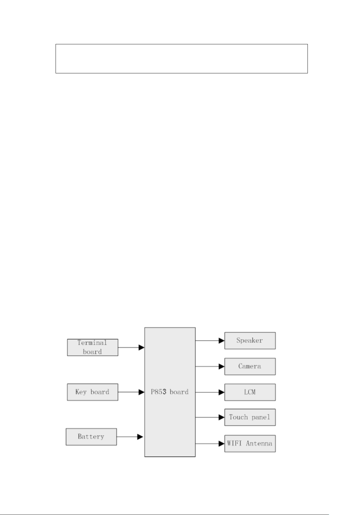
6. Block Diagram of The main board ...................................................................................... 10
页 1
Attention: This service manual is only for service personnel to take reference with. Before
servicing please read the following points carefully.
1. Safety precautions
1.1 Be sure to switch off the power supply before replacing or welding any components or
inserting/plugging in connection wire.
1.2 Antistatic measures must be taken (throughout the entire production process!):
a)Do not touch here and there by hand at will;
b)Be sure to use antistatic electric iron;
c)It’s necessary for the welder to wear antistatic gloves.
1.3 Please refer to the part list before replacing components that have special safety requirements.
Do not replace with different components with different specs and type at will.
2. Repair Tools
Multimeter、Oscilloscope、DC power、 PC(Should be installed FLASH program)
3. Wiring diagram
页 2
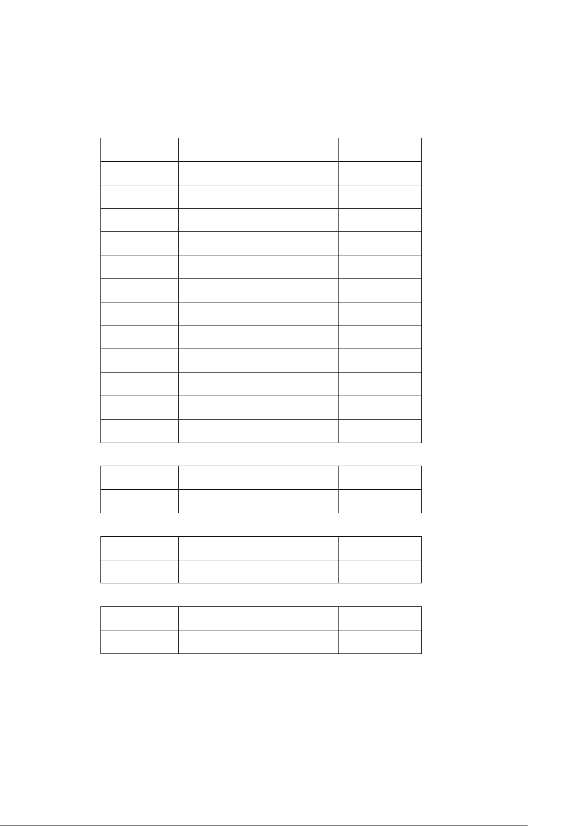
4. Power Voltage
4.1 U2 Output
Name Min. Typ. Max.
VDD_ARM 1.05 -- 1.45
VCC_DDR 1.47 1.5 1.53
VCC_IO 3.15 3.2 3.25
VCC18_CIF 1.48 1.5 1.52
VDD_11 1.08 1.1 1.12
VCC25_HDMI 2.40 2.5 2.60
VCCA_33 3.27 3.3 3.33
VCC_WIFI 3.27 3.3 3.33
VCC_25 2.47 2.5 2.53
VCC_18 1.78 1.8 1.82
VCC_RTC 1.78 1.8 1.83
VCC28_CIF 2.78 2.8 2.83
4.2 Q8 Output
Name Min. Typ. Max.
VCC_TF3V 3.15 3.2 3.25
4.3 U12 Output
Name Min. Typ. Max.
VDD_LOG 1.05 -- 1.35
4.4 Q1 Output
Name Min. Typ. Max.
LED_MAIN 3.4 -- 5.2
页 3