

Page 1

90cm Dual Fuel Range Cooker
Electric Ovens and Grill with Gas Hob
DF90
User Guide & Installation Handbook
®
Page 2

User’s Section . . . . . . . . . . . . . . . . . . . . . . . . . . . . . . . . . . . . . . . . . . . . . . . . . 3 - 22
Before Using Your Cooker. . . . . . . . . . . . . . . . . . . . . . . . . . . . . . . . . . . . . . . . . . . . . . 3
About Your Cooker. . . . . . . . . . . . . . . . . . . . . . . . . . . . . . . . . . . . . . . . . . . . . . . . . . . 4
Hob & Cooker Safety . . . . . . . . . . . . . . . . . . . . . . . . . . . . . . . . . . . . . . . . . . . . . . . . . 5
Chip Pan Fires . . . . . . . . . . . . . . . . . . . . . . . . . . . . . . . . . . . . . . . . . . . . . . . . . . . . . . 6
Using The Minute Minder . . . . . . . . . . . . . . . . . . . . . . . . . . . . . . . . . . . . . . . . . . . . . . 7
Using Your Gas Hob . . . . . . . . . . . . . . . . . . . . . . . . . . . . . . . . . . . . . . . . . . . . . . . . . . 9
Using Your Grill . . . . . . . . . . . . . . . . . . . . . . . . . . . . . . . . . . . . . . . . . . . . . . . . . . . . 10
Grilling Guide. . . . . . . . . . . . . . . . . . . . . . . . . . . . . . . . . . . . . . . . . . . . . . . . . . . . . . 11
Using Your Main Oven(s) . . . . . . . . . . . . . . . . . . . . . . . . . . . . . . . . . . . . . . . . . . . . . 12
Oven & Grill Functions . . . . . . . . . . . . . . . . . . . . . . . . . . . . . . . . . . . . . . . . . . . . . . . 13
Fanned Oven Guide . . . . . . . . . . . . . . . . . . . . . . . . . . . . . . . . . . . . . . . . . . . . . . . . . 14
Cooking Guide . . . . . . . . . . . . . . . . . . . . . . . . . . . . . . . . . . . . . . . . . . . . . . . . . . . . . 15
Roasting Guide . . . . . . . . . . . . . . . . . . . . . . . . . . . . . . . . . . . . . . . . . . . . . . . . . . . . 16
General Baking Guide . . . . . . . . . . . . . . . . . . . . . . . . . . . . . . . . . . . . . . . . . . . . . . . . 18
Cleaning Your Gas Hob. . . . . . . . . . . . . . . . . . . . . . . . . . . . . . . . . . . . . . . . . . . . . . . 19
Cleaning Your Cavities . . . . . . . . . . . . . . . . . . . . . . . . . . . . . . . . . . . . . . . . . . . . . . . 20
Cleaning Your Appliance . . . . . . . . . . . . . . . . . . . . . . . . . . . . . . . . . . . . . . . . . . . . . . 21
Cook Shop. . . . . . . . . . . . . . . . . . . . . . . . . . . . . . . . . . . . . . . . . . . . . . . . . . . . . . . . 22
Trouble Shooting . . . . . . . . . . . . . . . . . . . . . . . . . . . . . . . . . . . . . . . . . . . . . . 23 - 24
Before You Call . . . . . . . . . . . . . . . . . . . . . . . . . . . . . . . . . . . . . . . . . . . . . . . . . . . . 23
Changing Light Bulbs . . . . . . . . . . . . . . . . . . . . . . . . . . . . . . . . . . . . . . . . . . . . . . . . 24
Installation Instructions . . . . . . . . . . . . . . . . . . . . . . . . . . . . . . . . . . . . . . . . 25 - 32
Installing Your Cooker . . . . . . . . . . . . . . . . . . . . . . . . . . . . . . . . . . . . . . . . . . . . . . . 25
Technical Data. . . . . . . . . . . . . . . . . . . . . . . . . . . . . . . . . . . . . . . . . . . . . . . . . . . . 32
Service Record. . . . . . . . . . . . . . . . . . . . . . . . . . . . . . . . . . . . . . . . . . . . . . . . . . . . 34
Customer Care . . . . . . . . . . . . . . . . . . . . . . . . . . . . . . . . . . . . . . . . . . . . Back Cover
Contents
If you smell gas:
Do not try to light any appliance. Do not touch any electrical switch.
Call the Gas Emergency Helpline at TRANSCO on: 0800 111999
Page 3
Before Using Your Cooker
Before using this appliance please make sure that
you have removed all packaging and wrapping.
Some of the furniture inside this
appliance may have additional wrapping.
It is also advised that you turn the ovens and/or
grill on for a short while, this will burn off any
residues left from manufacturing. There may be a
smell which accompanies this process - but this is
nothing to worry about and is harmless.
We also recommend that you wash the oven
shelves, the baking tray, the grill pan, and the grill
pan trivet before their first use in hot soapy water,
this will remove the protective oil coating.
Although every care has been taken to ensure this
appliance has no burrs, or sharp edges, we
recommend that you wear protective gloves when
installing and moving this appliance.
This will prevent any injury.
Our policy is one of constant development and
improvement. Strict accuracy of illustrations and
specifications cannot be guaranteed. Modification
to design and material may be necessary
subsequent to publication.
Please bear in mind that not all the sections inside
this handbook are relevant to your appliance, but
you should read carefully the sections which are
relevant before installation and use. This will save
you time.
Always use a registered installer for this appliance.
Environmental protection:
Glen Dimplex Home Appliance brands are
committed to protecting the environment and
operates and Environmental Management System
which complies with BS EN ISO 14001.
All packaging with this appliance is recyclable and
environmentally friendly.
Please recycle whenever possible - contact your
local authority for your nearest recycling centre.
!!!
3
i
i
!!!
i
i
!!!
Page 4
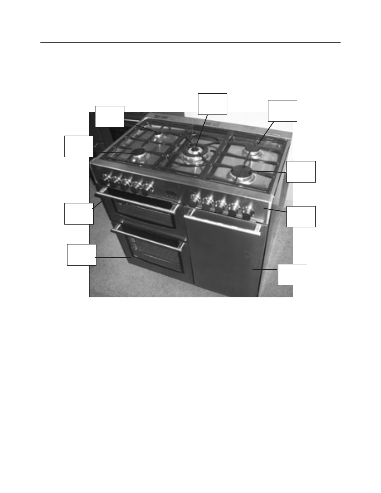
About Your Cooker
Fanned
oven
Fanned
oven
Fascia
panel
Grill
Large
burner
Wok
burner
Small
burner
Medium
burner
Medium
burner
4
Page 5

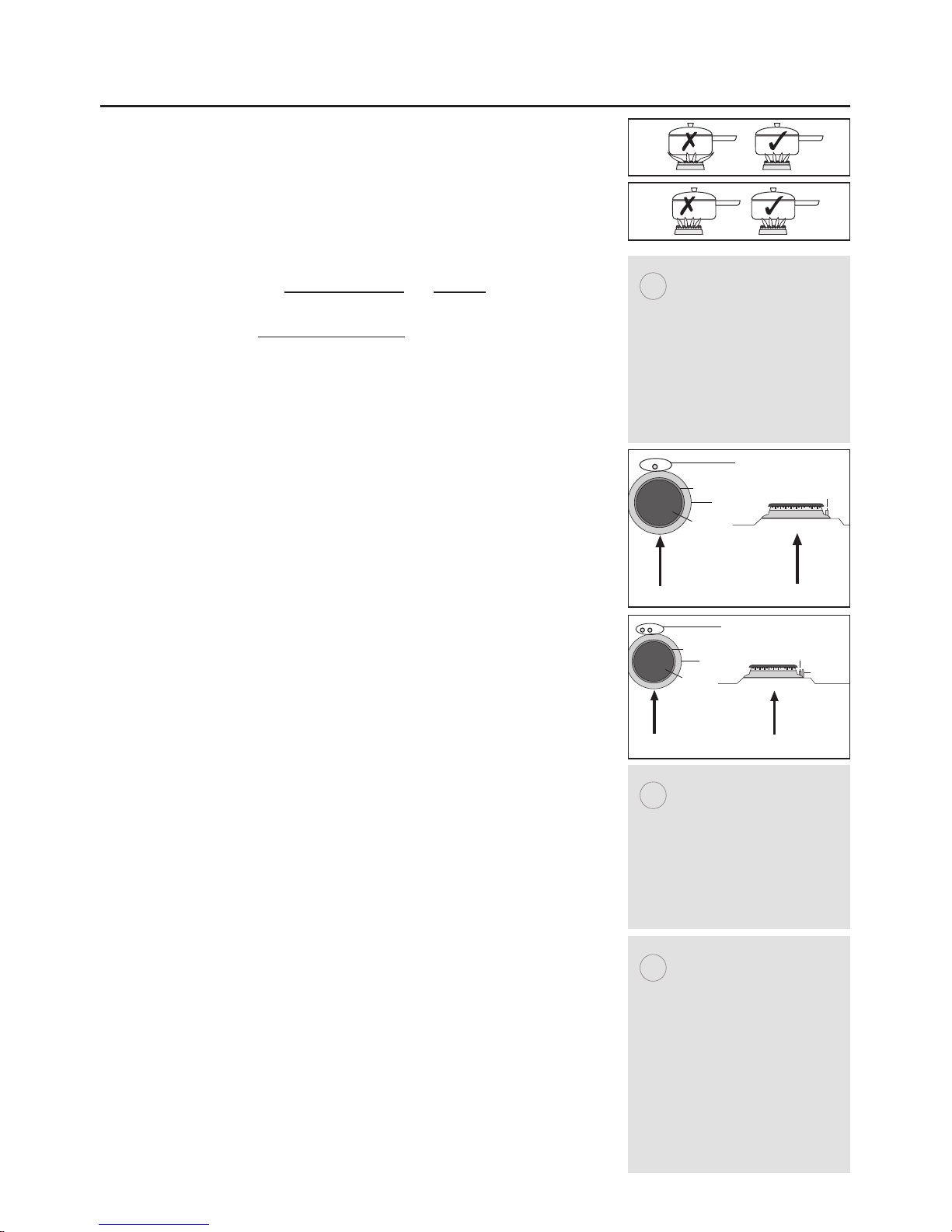
Hob & Cooker Safety
4Always ensure that pan bases are dry, and flat before
using them on the hob.
4Always position pans over the centre of the burner, and
turn the handles to a safe position so they cannot be
knocked or grabbed.
4Always use pans which are no smaller than 100mm
(4”), or larger than 250mm (10”).
4 Always take care when removing food from the oven
as the area around the cavity may be hot.
4 Always use oven gloves when handling any utensils
which have been in the oven as they will be hot.
4Always make sure that the oven shelves are resting in
the correct position in between two runners. Do not
place the oven shelves on top of the highest runner,
this will lead to spillage and injury if the baking tray, or
dish falls.
6 Never use double pans, rimbased pans, old or
misshapen pans, or any pan which is not stable on a
flat surface.
6 Never leave cooking fat, or oil, unattended.
6 Never use commercial simmering aids, or heat
diffusers, as they create excessive heat and can
damage the surface of the hob.
6 Never use the hob for any other purpose than cooking
food.
6 Plastic cooking utensils can melt if they come into
contact with a warm hob. Never leave them close to,
or on top of, the hob.
6 Never leave the burner alight without a pan covering it.
This causes a fire hazard.
6 Do not place items on the door while it is open.
6 Do not wrap foil around the oven shelves, or allow it to
block the flue.
6 Do not drape tea towels near the oven while it is on,
this will cause a fire hazard.
6 Do not pull heavy items, such as turkeys, or large
joints of meat, out fr
om the o
v
en on the shel
f, as they
may overbalance and fall.
6 Do not use this appliance to heat anything other than
food items, and do not use i
t f
or heating the r
oom.
5
Always make sure that the
burner caps, rings and
pansupports are correctly
placed. This will prevent pans
becoming unstable while in
use, and ensure an
uninterrupted gas flow.
Call Customer Care for a
service engineers visit if:
lThe cooling fan fails to
work.
i
WARNING: Parts of
the appliance may
become hot while in
use, always make sure
that children are
supervised when they
are near to the
appliance.
!!!
Page 6

Chip Pan Fires
What causes a chip pan fire?
l Chip pan fires start when oil of fat overheats and catches fire,
or when oil or fat spills on to the cooker because the pan has
been filled too high.
l They can also start when wet chips are put into hot oil,
making it bubble up and over flow.
Preventing a chip pan fire
l Never fill the pan more than a third full with oil of fat.
l Never leave the pan alone with the heat on - even for a few
seconds.
l Dry chips before putting them in the pan.
l Never put chips in the pan if the oil has started smoking.
Turn off the heat and leave the oil to cool down, or else it
could catch fire.
In the event of a chip pan fire
l If your chip pan does catch fire - don’t panic, and don’t move
the pan. Serious burns are often caused by picking up the
pan and running outside with it.
l If it is safe to do so, and you don’t have to reach across the
pan, turn off the heat.
l Never throw water, or use a fire extinguisher.
l If you can, drape a damp cloth or towel over the pan to
smother the flames.
l Leave the pan to cool down for at least half an hour.
l If you can’t control the fire yourself, close the door, get out
and tell everybody else to get out.
l Call the fire brigade. Don’t go back inside whatever the
reason.
6
Page 7
Using The Minute Minder 7
The digital timer enables you to set the time of day (24
hour clock) and the minute minder alarm.
Setting the time of day
u Press the Plus and Minus buttons together for a few
seconds and release.
u Set the time of day using the Plus and Minus buttons.
Press once for single digit increase, press and hold for
rapid increase..
u Once the time of day has been set, wait approx 10
seconds until the ‘
l’ stops flashing.
u Use the appliance as normal.
Changing the time of day
1. Press the function button once.
2. Set the time of day, using the
plus
and
minus
buttons.
3. The time will be set 7 seconds after the last
plus
or
minus
operation.
Alarm tones
After setting the time of day, you can select one of three
alarm tones.
u Press the
minus
button to listen to the first tone, then
release the
minus
button and press again to listen to
the second tone, etc.
u Releasing the
minus
button after a tone has sounded
will automatically select that tone.
Use to set
the correct time
Minus
button
Plus
button
Function
select
Press &
release:
to set
the time
Page 8
Using The Minute Minder 8
Setting the minute minder
1. Press and release the
plus
button, to change the display from clock to minute minder - the bell symbol will
light.
2. Use the
plus
and
minus
buttons to set the length of
time before the alarm tone will sound. The display will
increase / decrease in units of 10 seconds up to 99
minutes, 50 seconds, and in units of 1 minute from 1
hour 40 minutes upwards. The maximum period which
may be set is 10 hours.
u The display format will change after 99 minutes and 50
seconds to 1 hour and 40 minutes.
u During countdown, the minute minder has priority on
the display, which will show (in
minutes : seconds, or
hours : minutes
) the time remaining.
u When countdown is complete, the tome will sound for
7 minutes, or it can be reset with one touch of any
button.
To cancel the minute minder at any time.
u Run down the set time with the
minus
button. The
display will show the time of day
Use to set
the correct time
Minus
button
Plus
button
Function
select
Press &
release:
to set
the time
Page 9
Using Your Gas Hob
Hob Ignition
Models without thermocouples:
l
To turn on
, place your pan onto the pansupports above
the burner you wish to use.
l Push in and turn the selected control knob
anticlockwise, to the full on symbol.
l If your hob has an ignition button or switch on the
fascia, press it in until your burner lights.
l If your hob has automatic ignition it will spark next to
the burner when you push in the control knob.
l
To simmer
, turn the control knob to the small flame
symbol. This will ensure that the flame is just large
enough to gently heat the contents of the pan.
l
To turn off
, turn the control knob clockwise to the ‘off’
position.
l Always make sure that your pans are place correctly on
the burners as shown, and do not allow the flame to
extend over the base of the pan.
Models with thermocouples:
Igniton as above, but:
l Hold the control knob in for 15 seconds. Do not hold
the control knob in for any longer than 15 seconds. If
the burner fails to light within this time, release the
control knob and wait one minute before attempting to
re-ignite.
Energy Saving
l Position pans centrally over the elements.
l Only heat the amount of liquid you need.
l Once liquids have been brought to the boil, reduce the
heat setting to a simmer.
l Consider using a pressure cooker if possible.
l Vegetables in small pieces will cook quicker.
l Use a pan which is a close match to your element size.
l Smaller elements are ideal for simmering and stewing
in smaller pans, while the larger elements are ideal for
frying and boiling
9
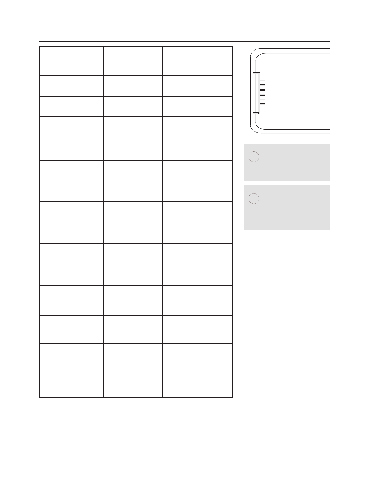
Front
of the appliance.
Burner cap
Burner ring
Burner skirt
Electrode
Electrode
Viewed from the side
of the burner
Front
of the appliance.
Burner cap
Burner ring
Burner skirt
Thermocouple and electrode
Thermocouple
Electrode
Viewed from the side
of the burner
How can I tel
l if my hob
has thermocouples?
Picture A below:
shows a burner without
thermocouples.
Picture B below:
shows a burner with
thermocouples.
i
A
B
In the event of a power
failure, or the ignition
not working:
Push in and turn the
control knob to start the
gas, then hold a lighted
match or taper to the
burner until it lights.
i
Use flat based pans
which are the correct
size for your burners
and suitable for your
hob type.
W
e recommend the
following sizes:
100mm or 4” min.
250mm or 10” max.
Smaller or larger pan
sizes may lead to slower
cooking times.
i
Page 10

Using Your Grill
Before you start grilling. . . .
Before you use the grill, make sure you have placed the
grill shelf in the position you need as once the grill is on
you may injure yourself if you try to move the shelf.
l Do not close the door while the grill is in use.
l Turn the selector control knob to the heat setting you
require.
l To switch off, return the control knob to the ‘off’
position.
l The cooling fan will come on during use, and may
continue to run for some time afterwards.
l To adjust your results, you can turn the grid over, or
remove it altogether.
If your grill is a dual grill:
l The
dual grill
uses all of the top element and is ideal for
grilling large quantities of food.
l The
single grill
uses part of the element only, and is
better suited to grill smaller amounts of food.
The grill pan
This appliance comes with a grill pan, grill pan handle and
a grid.
The handle of the grill pan is detachable to allow you to
remove it while the pan is in use, this stops it from
getting hot.
To attach the handle:
Place the handle over the narrow edge of the grill pan
and slide to the centre as shown in the diagrams.
Shelf & Grid adjustments
Speed of grilling can be adjusted by changing the shelf
position or the turning the grill pan grid.
l High: For thin foods and toasting.
l Low: For thicker meat pieces.
Aluminium Foil
Never cover the grill pan or grill trivet with foil, or allow fat
to build up in the grill pan, as this creates a fire hazard.
10
Warning: Accessible
parts may become hot
when the grill is in use.
Chidren should be kept
away.
handle
grill pan
grid
handle position
indicators
Please note: the grill
pan handle is designed
for sliding the grill pan
into and out of the grill
cavity. It is not to be
used for lifted the pan.
Types of grill
Fixed rate grill: has a
full ‘on’ setting and ‘off’.
V
ariable rate grill: has
adjustable heat settings
1 (low) to 8 (high) or 5
(high) - depending on
the model.
Single gri
ll: has one grill
element.
Dual grill: has two grill
elements which can be
used together, or as a
single grill.
i
i
i
For best results:
Pre-heat the grill for
about 3 minutes.
i
Page 11
Grilling Guide
Food
Type
Shelf
Position
Time Approx
(mins)
Bacon 5 8 - 15
Sausages 5 12 - 15
Chops
l Lamb
l Pork
4
3
10 - 15
15 - 25
Toast
l 2 rounds
l 4 rounds
5
5
1 - 2 (per side)
1 - 2 (per side)
Bread products
l Buns
l Tea cakes
4
4
1 - 2 (per side)
1 - 2 (per side)
Cheese on toast
l 2 rounds
l 4 rounds
5
5
4 - 5
4 - 5
Fish:
l fillets 2 10 - 15
Chicken:
l fillets
Depends on thickness
1 - 2
20 - 30
Beef Steaks:
l rare
l medium
l well done
Gammon Steaks
5
4
4
5
7 - 10
10 - 15
15 - 20
12 - 15
11
1
2
3
4
5
Note:
Shelf positions are
counted from the
bottom up.
i
As with any cooking
guide, all times are
approximate and can be
adjusted to suit
personal taste.
i
Page 12

Using Your Main Ovens
Switching on the fanned oven
l Use the main oven control to turn your oven on, and
select your temperature.
l The thermostat indicator will come on to show that the
oven is heating, and once the temperature is achieved,
it will go out.
l To switch off the main oven, simply turn the control
knob back to the ‘
l ‘ position.
l The cooling fan will come on during use, and may
continue to run for some time afterwards.
12
Page 13

Oven & Grill Functions
Main Oven Function Recommended Uses
Base Heat Only Used to finish off the bases of food following cooking using the conventional
or fanned modes. The base heat can be used to provide additional
browning for pizzas, pies and quiche. Use this function towards the end of
cooking.
Top Heat Only The heat is ideal from browning off the tops of food as it is not as fierce as
the grill following conventional or fanned cooking. Provides additional
br
owning for dishes like Lasagna or Cauliflower cheese. Use this function
towards the end of
cooking.
Conventional Oven This function is ideal for traditional roasting. The meat is placed in the
middle of the oven, roast potatoes towards the top.
Intensive Bake Suitable for food with a high moisture content, such as quiche, bread and
cheesecake. It also eliminates the need for baking pastry blind.
Fanned Grill The fan allows the heat to circulate around the food. Ideal for thinner foods
such as bacon, fish and gammon steaks. Foods do not require turning. Use
with the oven door closed.
Fanned Oven The even temperature in the oven makes this function suitable for batch
baking, or batch cooking foods.
Defrost To defrost foods, such as cream cakes/gateaux, use with the oven door
closed. For cooling dishes prior to refrigeration, leave the door open.
Dual Grill This function cooks food from the top and is ideal for a range of food from
toast to steaks. As the whole grill is working, you can cook larger quantities
of food.
Single Grill For smaller quantities of food, but is still ideal for
anything from toast to steaks.
Base Heat with Fan Used to cook open pies (such as mince pies) the base element ensures that
the base is cooked while the fan allows the air to circulate around the filling
- without being too intensive.
Lights only Use when the oven is switched off and cold to aid cleaning the oven cavity.
The chart below details all of the functions which are available. Your oven may
not have all of the functions shown here.
13
Page 14

Fanned Oven Guide 14
Conventional
temp (˚C)
‘A’ Efficiency oven
(˚C)
Gas mark
100
110
130
140
150
160
180 - 190
200
220
230
250
100
110
120
130
140
150
160
170
180
190
200
1/4
1/4
1/2
1
2
3
4 - 5
6
7
8
9
l Some adjustment will have to be made to conventional
cooking temperatures.
l The table below shows conventional cooking
temperatures, fanned temperatures and gas marks.
For optimum results using the fanned oven setting,
conventional temperatures need to be converted to the
fanned oven temperatures.
l For example and item which would cook at 180˚C will
now cook at the fanned oven temperature of 160˚C.
l This is a high efficiency oven, you may notice an
emission of steam when the door is opened.
l When cooking chilled or frozen foods, use the
recommended cooking times and temperature on the
packaging.
Always make sure the food is piping hot
throughout before serving.
l There are no zones of heat, and no flavour transfer when
using a fanned oven - allowing you to cook a greater
variety of foods together.
l If you are cooking on more than one shelf, you may need
to slightly increase the cooking time.
l Always make sure that there is enough space between
dishes, to allow food to rise, and to air to circulate.
Page 15

Pre-heating
To get the best results from your oven, we recommend
pre-heating for around 5 to 15 minutes before placing
your dishes in. This is especially important for items
which are chilled, frozen, batter based, yeast based or
whisked sponges.
If you are using a fanned function, you should still preheat but for a shorter time.
The items in the cooking guide below are based on a
pre-heated oven, but can be adjusted to take into account
personal taste.
Oven and bakeware
Always use high quality trays and tins for cooking. Poor
quality tins and trays can warp in the oven producing
uneven results.
Never use dishes which are cracked, damaged or not oven
proof as heating may lead to shattering inside the oven.
Food Type Temp.
Setting ˙C
Time
Approx.
Shelf
Position
Cakes
Small cakes
Victoria sandwich
Semi rich fruit cake
Christmas cake
Fanned
160
160
125
125
15 - 25
20 - 30
2
1/2
- 3hrs
2
1/2
- 3hrs
7 & 13
7
5
3
Puddings
Bread & butter
pudding
Fruit crumble
150
175
45 - 1hr
40 - 1hr
9
9
Miscellaneous
Yorkshire pudding:
large
small
Shortcrust pastry
200
200
180
40 - 45
15 - 20
depends on
fi
l
l
ing
11
12
top - middle
Cooking Guide 15
Page 16

Roasting Guide
l Roasting times depend on the weight, shape and texture
of the meat and personal preference. In order to
calculate the roasting time, weigh the meat or poultry,
including the stuffing, and follow the times given
below.
l Frozen meat must be thoroughly thawed before
cooking. For large joints, it is advisable to thaw
overnight.
l Frozen poultry must be thoroughly thawed before
cooking. The time required depends on the size of the
bird - eg: a large turkey may take up to 48 hours to
thaw.
l When cooking stuffed meat or poultry, calculate the
cooking time from the
total weight of the meat plus the
stuffing.
l Cooking joints in foil, covered roasters, lidded
casseroles, or roasting bags will help to reduce meat
shrinkage, give a more moist result and may reduce fat
splashing. However, a slightly longer cooking times will be
required,
add 5 - 10 minutes per 450g (1lb) to the
calculated cooking time. When using roasting bags do
not exceed the temperatures recommended by the
manufacturer, and do not allow the roasting bag to touch
the sides or top of the oven.
l Use of a trivet with the roasting tin will reduce fat
splashing during open roasting, and will help to keep the
oven interior clean.
l The use of a roasting tin larger then that supplied is not
advised, as this may impair performance and lead to
extended cooking times.
Meat joints (including chicken) should be roasted at
180 - 200˚C Conventional/ 160 - 180˚C Fanned for
20 - 30 mins per 450g/1lb, plus 20 minutes on shelf
position 2.
16
Page 17

Roasting Guide
Roast turkey
l Roasting turkey perfectly involves cooking two different
types of meat - the delicate light breast meat, which
must not be allowed to dry out, and the darker leg meat,
which takes longer to cook.
l The turkey must be roasted long enough for the legs to
cook, so frequent basting is necessary. The breast meat
can be covered once browned.
l The turkey can be open roasted, breast side down, for
half of the cook time, and then turned over for the
remainder of the cooking time.
l If the turkey is stuffed, add 5 minutes per 1lb to the
cooking time.
l If roasting turkey covered with foil, add 5 minutes per
1lb to the cooking time.
l To test if the turkey is cooked, push a fine skewer into
the thickest part of the thigh. If the juices run clear, the
turkey is cooked. If the juices are still pink, the turkey
will need longer cooking. Always make sure that the
turkey is cooked properly before serving.
The
mmaaxxiimmuum
m
size Turkey for this appliance is: 20lbs
approximately 9kgs.
Please do not attempt to roast a Turkey larger than this, as
the results cannot be guaranteed.
TTuurrkkeeyy RRooaassttiinngg ttiimmeess.
.
Most Turkeys are measured by the kilogram. Timing should
be calculated in either of these ways:
40 minutes per 1kg plus 10 minutes per 1/4 kg.
or
20 minutes per 1lb, plus 20 minutes.
Turkey should be roasted at 180 - 200˚C
Conventional/ 160 - 180˚C Fanned for 20 - 30 mins
per 450g/1lb, plus 20 minutes.
17
Page 18

General Baking Guide 18
Trouble-shooting - Fruit Cakes
Trouble-shooting - Sponge Cakes
PROBLEM POSSIBLE CAUSE
Fruit sinking to the bottom Low oven temperature which may cause the cake to
take longer to set, allowing the fruit to sink. Or, too
much liquid, or raising agent. The fruit may not have
been properly washed and dried.
Cake sinking / dipping in the centre Too much raising agent in the mixture. Too hot, or too
cool an oven. Or, not enough liquid or insufficient
creaming.
Surface cracks Too small a tin, or too much mixture in the tin. Too
much raising agent in the mix, plus not enough liquid
or insufficient creaming. The oven may be too hot.
Hard outer crust with a damp patch inside Oven too hot, therefore the cake baked too quickly.
Too much sugar, or insufficient liquid.
Burnt outside Oven temperature too high. Oven too small for the
size of cake. Insufficient protection around the tin.
Cake baked on too high a shelf.
Texture with pronounced holes. Too much raising agent. Flour unevenly mixed.
Texture too close and cake insufficiently risen. Not enough raising agent. Not enough liquid. Too cool
an oven. Insufficient creaming.
Cake crumbles when cut Not enough liquid. Baked for too long. Not enough
sugar. Too much baking agent.
Too dry Over baking. Insufficient egg or liquid. Too much rais-
ing agent.
Domed top Insufficient creaming of mixture. Cake baked on too
high a shelf position, or at too high a temperature.
Paper liners can cause the outer edge not to rise and
the centre to peak.
Hollowed / sunk
en top
Too much r
aising agent. Oven temperature too low, or
incorrect shel
f position. Cake removed from oven
bef
ore it’s cooked. Use of soft tub margarine.
Very pale, but cooked Oven temperature too low. Baked too low in the oven
Ov
erflowing tin
Tin too smal
l for the amount of mixture
Page 19

Cleaning your Gas Hob
Sometimes when a hob is not working well, it is because
it needs cleaning.
Enamel parts
l Use a mild cream cleaner for example ‘Cif’. Stubborn
marks can be removed with a soap filled pad.
Stainless steel surfaces
l Only use a clean cloth wrung out with warm, soapy
water and dried off with a soft cloth. For stubborn
marks use a specialist stainless steel cleaner.
l Do not use steam cleaners.
l Sharp implements and objects can mark the surface of
stainless steel, however they do become less noticeable
in time.
Cast iron parts
l Ensure the parts have fully cooled and scrape off any
stubborn marks, and bits of food with a plastic, or
wooden cooking implement. Rinse in warm soapy
water and dry with a tea towel.
l Do not clean in a dishwasher.
l If you notice any rusting on your griddle, or
pansupports, simply clean in warm soapy water, then
re-season.
Burner caps and heads
The slots in the burner head where the flames burn
should be cleared of deposits.
l Clean with a nylon brush, rinse and then dry
thoroughly. There may be brownish coloured markings
on your burners, these are carbon deposits or fat stains
and can be removed using a soap filled pad.
l Do not put burners in the dishwasher or soak them.
Using dishwasher powders, washing up liquids and
caustic pastes can damage the burners.
l Burner caps and heads must be repositioned correctly
so that they sit squarely on to the hob as shown on the
the left.
l This is particularly important with stainless steel models
as failure to reposition the caps correctly may result in
discolouration of the stainless steel around the burners.
Painted & Plastic parts
l Only use a clean cloth wrung out in hot soapy water.
19
Baby oil can be used to
r
estore stainless steel
finishes - but only use a
few drops. Don’t use
cooking oils as they can
contain salts which will
damage the metal.
Always allow your
appliance to cool
down, and switch off
the electricity before
you clean any part of
it.
!!!
i
Don’t use:
undiluted bleaches,
products containing
chlorides, wire wool or
abrasive cleaners on
aluminium, stainless
steel, or plasitic/painted
parts they can damage
the appliance. Nylon
pads can also be
unsuitable
i
incorrect
burner cap not central
incorrect
angled
correct
parallel
burner cap
burner head
Page 20

Cleaning your Cavities
Cleaning the oven cavities
l Some foods can cause fat to spit, especially if you have
open roasted, this leaves the inside of the cavity
greasy.
l It is important to clean the oven cavity as a build up of
fat can damage the appliance and may invalidate your
guarantee.
Chrome plated parts.
l Use a moist soap filled pad, or place in a dishwasher.
l Shelf runners can be removed to enable you to clean
then thoroughly. Make sure they are cool to touch and
then grasp the runners and slide out of their hanging
holes.
Vitreous enamel surfaces
l The enamel can be cleaned by wiping the surfaces
with a clean cloth which has been wrung out in hot,
soapy water.
l Stubborn marks can be cleaned using a moistened
soap filled pad, or a mild cream cleaner.
l Rinse well, and allow to dry before use.
20
Pull out to clean
Always allow your
appliance to cool
down, and switch off
the electricity before
you clean any part of
it.
!!!
Don’t use:
Caustic or abrasive
cleaners, bleaches,
coarse wire wool or
hard impliments,
these will damage
your appliance.
i
Using a trivet while
roasting meat may help
to reduce fat splashes.
i
Page 21

Baby oil can be used to
restore stainless steel
finishes - but only use a
few drops. Don’t use
cooking oils as they can
contain salts which will
damage the metal.
Take extra care when
cleaning over symbols
on fascia panels,
excessive cleaning can
lead to the symbols
fading.
Always allow your
appliance to cool
down, and switch off
the electricity before
you clean any part of
it.
Cleaning your Appliance
Painted & Plastic parts
l Only use a clean cloth wrung out in hot soapy water.
l Do not use abrasive cleaners, such as “Cif”, wire or nylon
cleaning pads on these parts.
Stainless steel & Aluminium surfaces
l Only use a clean cloth wrung out in hot soapy water, and
dry with a soft cloth.
l Stubborn marks can be removed using a stainless steel
cleaner. Supplies can be purchased from the Customer
Care Centre.
l Sharp objects can mark the surface of stainless steel, but
will become less noticeable with time.
l Wipe any spillage immediately, taking care to avoid burn-
ing your hands.
l Some foods are corrosive eg; vinegar, fruit juices and
especially sal
t - they can mark or damage the metal if
they are left on the surface.
Enamel surfaces & parts
l Clean with warm, soapy water and a clean cloth.
l Dry with a soft clean towel or cloth.
l Do not use steam cleaners.
Glass parts
l Only use a clean cloth wrung out in hot soapy water, or
a specialist glass cleaner.
l Rinse away any excess cleaner and dry with a soft cloth.
l Do not use abrasives or polishes as they will scratch and
damage the glass.
l The inner door glass panel can be removed for cleaning
but it must be replaced the right way up. If there is any
writing on the glass, you must be able to read it clearly
when the cavity doors are open.
l Always make sure that the glass is pushed fully into the
Stop position.
l To remove the glass panel, open the door wide, hold the
top and bottom edges and slide out.
l
WWaarrnniinng
g
:
Do not
operate the appliance without the glass
panel correctly fitted.
21
!!!
i
i
Don’t use:
undiluted bleaches,
products containing
chlorides or abrasive
cleaners on aluminium
or stainless steel, they
can damage the
appliance.
i
Glass door panels
For your safety, glass door
panels are made of toughened
glass. This ensures that, in
the unlikely event that a panel
breaks, it does so into small
fragments to minimise the risk
of injury.
Please take care when
handling, using or cleaning all
glass panels, as any damage
to the surfaces or edges may
result in the glass breaking
without warning or apparent
cause at a later date.
Should an
y glass panel be
damaged, we strongly
recommend that it is replaced
immediately
.
Page 22

Cook Shop
Product
description
Product
code
Quantity Where used
Rectangular
carbon filters
082612620 2 Hoods
Round carbon
filters
082611571 1 Hoods
Ceramic hob
scraper kit
082606781 1 All ceramic glass
hobs including
induction.
Ceramic hob
cleaner and
conditioner
082606780 1 All ceramic glass
hobs including
induction
Sealed hotplate
conditioner
082606783 1 All sealed / solid
plate hobs.
Stainless steel
cleaner
082606764 1 All stainless steel
parts
Oven cleaner
spray
082606786 1 All cookers, inside
cavities and on
glass.
Multi-purpose
kitchen
cleaner
082606782 1 General kitchen
cleaner.
E-cloth 082813300 1 All cookers, for
cleaning glass and
stainless steel
To order or enquire about any
of these products, please call
the Spares Sales team on:
0870 458 9961.
22
Page 23

Before you call. .
Problem? Advice
The ignition won’t work.
(Gas and dual fuel models)
l Check ther
e is a spark when the
igni
tion button is depressed. If
there is no spark, check the
electrici
ty supply is switched on at
the sock
et.
l Check that the gas supply is
switched on.
l Try another appliance in the
socket, if that works replace the 3
amp fuse in the cooker plug.
There’s condensation on the
doors.
Condensation is caused by hot,
moist air meeting a cooler surface
(i.e. the oven door). You cannot
always prevent it, but you can
minimise it when it happens by
doing the following:
l Pre-heat the oven at a high
temperature before putting food in
the oven, and cover the food you
are cooking wherever possible.
l Whenever you can, cook wet
foods at higher temperatures.
l Don’t leave food in the oven to
cool down.
Automatic cooking will normally
produce condensation when the
oven is cooling down with food
inside.
There’s been a power failure
and the oven won’t work.
(models with clocks and
automatic programmers)
l Switch off the electricity supply.
l When the power returns - re-set
the programmer/Clock to the
correct time of day.
This will allow you to use your
appliance.
23
Page 24

No. of
lamps
Bulb
Location
Oven
type
Instruction for
changing the bulb
2
(@25W)
side All Wait until the oven is cool,
then remove the oven
shelves.
Grasp the lens cover on the
light fitting and pull it away
from the side of the oven.
Unscrew the bulb.
1
(@25W)
rear Fanned /
Multifunction
Wait until the oven is cool,
then remove the shelves.
The oven light is at the rear
of the oven cavity.
Remove the loose oven back
- unscrew the 4 securing
screws (one at each corner).
Unscrew the lens cover (turn
anticlockwise). Unscrew the
bulb and replace. Replace
lens cover and replace oven
back.
1
(@25W)
r
ear
Con
ventionalWait until the oven is cool,
then remove the oven
shelves.
The ov
en light is at the rear
of the o
ven cavity.
Unscrew the lens cover (turn
anticlockwise). Unscrew the
bulb and r
eplace. R
eplace
lens cover.
Changing Light Bulbs
Warning: There is a risk of electric shock, so always
make sure you have turned off and unplugged your
appliance.
Not all appliances have the same number and type of
bulbs. Before replacing your bulb, open the top/main
oven door and see which type you have. Then use the
table to help you change your bulb correctly.
Please remember that bulbs are not covered by
your warranty.
Bulbs can be purchased from hardware stores (always
take the old bulb with you).
24
There is no need to remove
the oven back on the 90DF
model.
Page 25

Installing Your Cooker 25
Clearances
This cooker may be fitted flush to the base units of your
kitchen.
l No shelf, overhang, cupboard, or cooker hood should
be less than 650mm above the hob top, but please
check this with the hood manufacturers instructions.
l If your appliance has a side opening door, we
recommend a side clearance of 60mm to allow the
oven door to fully open.
l The cooker must have a side clearance above hob level
of 90mm up to a height of 400mm.
l The important dimensions are those around the
appliance.
650mm
minimum
400mm
clearance
Flush fit to
base units
Flush fit to
base units
90
mm
90
mm
For all appliance sizes:
700mm
800mm
900mm
1000mm
1100mm
1200mm
Page 26

Installing Your Cooker
The information below is crucial to installing this appliance
correctly and safely.
Where standards have been revised - always use the most
recent edition.
Failure to install appliances correctly is dangerous
and could lead to prosecution.
Ventilation Requirements
The room containing the appliance should have an air
supply in accordance with BS 5440:Part 2.
l All rooms require an openable window, or equivalent,
and some will require a permanent vent as well.
l For room volumes up to 5m
3
an air vent of 100cm3is
required.
l If the room has a door which opens directly to the
outside, or exceeds 10m3- no air vent is required.
l For room volumes between 5m
3
and 10m3and air vent
of 50cm2is required.
l If there are other fuel burning appliances in the same
room, BS 5440:Part 2 should be consulted to determine
the air vent requirements.
l This appliance must not be fitted into a bed sitting room
of less than 20m3or into a bath or shower room.
Windows and vents should not be blocked or removed
without first consulting a competent engineer.
LPG only - do not install this appliance below ground
level. This does not preclude installation into rooms which
are basements with respect to one side of the building, but
open to ground level on the opposite side
.
26
Page 27

Installing Your Cooker
The information below is crucial to installing this appliance
correctly and safely.
Failure to install appliances correctly is dangerous
and could lead to prosecution.
UK Regulations & Standards
always refer to the most recent issue of the standards
l Gas Safety Regulations.
l Building Regulations - issued by the DEFRA.
l Building Standards (Scotland) (Consolidated) - issued by
the Scottish Development Department.
l I.E.E. Wiring Regulations.
l Electricity at Work Regulations.
l BS 6172 Installation of Domestic Gas Cooking. For LP
Gas, refer to BS 5482 Part 1, Part 2 or Part 3 as
relevant.
l Installation and Servicing Instructions for this appliance.
For installation in countries other than the UK, the appliance
must be connected in accordance with all local gas and
electrical regulations.
In the Republic of Ireland installers should refer to IS 813
Domestic Gas Appliances.
27
Page 28

Fitting the plinth (if applicable)
l Make sure the appliance is raised to a height of 915mm
or above before beginning.
If the appliance is below
915mm - you can only fit the plinth cover labelled
X
X
.
You can adjust the height using the feet (1) of the
appliance.
If your appliance has a storage drawer at the bottom,
you access the required holes through the base of the
drawer after lifting the mat.
l Open the appliance doors, and loosen screw A located
on bracket (2). Do not remove this screw entirely.
l Insert screw B, through slot (3) and screw into the small
hole at the bottom of bracket (2).
Make sure that the plinth cover is flush to the appliance,
but not over tightened.
Fitting the splashback (if applicable)
l Loosley fit screw A and nut B into hole 1 at both ends of
the rear surface of the appliance.
l Locate fitted screw A through the slots in both of the
metal splashback plates.
l Tighten screw A and nut B.
l Now locate and tighten screw C and nut D through hole
(2) at both ends of the rear surface of the appliance.
Make sure that the splashback is securely attached, but
avoid over tightening.
Fitting the towel rail (if applicable)
l On the towel rail there are two hole, top (A) and bottom
(B), these holes have corresponding holes on the fascia
at each end.
l The scr
ew f
or the top hole (A), must be screwed into
the supplied adaptor, whereas the remaining screw just
goes thr
ough the bot
tom hole (B). B
oth scr
ews ar
e M6
scr
ews. Using the al
len key provided, tighten the screws
making sure that the towel rail is flush to the fascia,
but not over tightened.
Installing Your Cooker 28
B
A
(1)
(2)
(3)
X
Y
Door
Plinth cover
Oven cavity
B
(1)
A
D
C
(2)
A
B
Page 29

Stabilising and Securing
Your cooker may come with a stability chain, if it does not
we recommend that you buy a stability bracket from your
local supplier, this will keep the cooker from moving and
will prevent damage to the flexible hosing at the back of
the cooker.
Your stability chain
Your cooker must be secured to a wall or a solid partition
behind the cooker.
Your stability bracket
You can buy a stability bracket from your supplier and it
can fitted as follows:
l Place the cooker in position and draw a pencil line level
with the front edge.
l Remove the cooker and mark off 450mm from the
pencil line to locate the front edge of the lower
bracket.
l Fix the bracket to the floor. Measure from floor level to
engagement edge in the back of the cooker and add
3mm.
l Assemble the underside of the top part of the bracket
to this height.
l See the drawings for the location of the bracket and
the recommended positioning.
Levelling
Once your cooker is secure:
Place a spirit level onto a baking tray, on an oven shelf.
These cookers are fitted with adjustable feet which will
allow you to adjust the height of the appliance until it is
level. The adjustable feet are at the rear of the cooker.
Installing Your Cooker 29
Stability Hook
(not supplied)
Rear of cooker
Firmly fix chain
to cooker rear
Stability chain to
be as short as
possible
Cooker stability chain not designed
with bracket engagement slot
Stability bracket
1 Pencil line
on floor
2 Centre
of range
3
450
mm
Front edge for
lower bracket
4
5 Underside of top bracket
slots into engagement
edge in back of cooker.
Rear wall
Gas inlet pipe
Centre of appliance
Model viewed from rear
Locate stability bracket here
X
Rear
plinths
Back panels
Rear feet and
wheels
Page 30

Installing Your Cooker
Connecting the electricity supply
Warning: This appliance must be earthed!
l This appliance must be fitted using a double pole unit
of 30 ampere minimum capacity with 3mm minimum
contact at all poles.
l Access to the mains terminal is gained by opening the
terminal block cover at the rear of the appliance - use
a flat bladed screw driver for this.
l Connection should be made with a 6.0mm
2
twin and
earth cable.
l First strip the wires. then push the cable through the
cable clamping the terminal block cover.
l Connect the cable to the terminal block and tighten the
cable clamp screw - see diagram.
l Close the terminal box, ensuring that the cover is
engaged on the locking tabs.
l Sufficient cable should be used to allow the cooker to
be pulled out, but must hang clear of the floor so it
does not become twisted or trapped when the cooker
is pushed back.
Please ensure that the user has this copy of the
handbook, and the appliance is in place. Thank you.
1
2
3
4
5
Cable
clamp
Earth
(Green / Yellow
or sleeving)
Live
(Red or Brown)
Neutral
(Black or Blue)
30
Page 31

Installing Your Cooker
Connecting to the gas supply
The inlet to the appliance is ISO 7 - Rp
1
⁄2
” internal thread
situated towards the top right corner of the rear.
Fit the bayonet connection. This should be located so as
to ensure that the flexible hose does not kink.
Use a 900mm - 1125mm length of flexible hose.
Ensure that all pipe work is of the correct rating.
Natural Gas - Flexible connections should comply with
BS 669. Parts of the appliance likely to come into contact
with a flexible connector have a temperature of less than
70˙C.
LP Gas - For flexible connections use a bayonet type
hose, suitable for use on LP Gas up to 50mbar pressure
rise and 70˙C temperature rise. The flexible hose should
be coloured black with a red stripe, band or label. If in
doubt, contact your supplier.
After installation make sure all connections are gas
sound.
Commissioning
Pressure settings:
G20 Natural Gas @ 20mbar
G30 Butane @ 28-30mbar
G31 Propane @ 37mbar
Hob
Turn on gas supply and check for soundness at the hotplate injector. Light two burners and check that the pressure is correct.
31
Page 32

Technical Data - Notes 32
Type of gas:
Natural Gas I2H
Natural Gas II2H3+*
LP Gas I3+
Please see your data badge for specified gas
type.
* Can be converted from Natural gas to LP Gas
Never attempt to convert an appliance unless the data badge states that you can.
Burner Aeration:
Fixed
Pressure setting:
G20 Natural Gas @ 20mbar
G30 Butane @ 28-30mbar
G31 Propane @ 37mbar
Electrical supply:
220 - 240V ~ 50Hz
Countries of destination:
GB
!!!
Page 33

Technical Data - Notes 33
Fuel Type Hotplate Burner /
Element
Nominal Rate
Qn
Butane
g/h
Propane
g/h
Injectors
used
Natural Gas
Hob - small
Hob - medium
Hob - Large
Hob - wok
Total heat input
l
5 burners
1.0kW
2.0kW
3.0kW
3.5kW
11.5kW
-
-
-
-
-
-
-
-
-
-
77
104
129
121 & 63
LP Gas
Hob - small
Hob - medium
Hob - Large
Hob - wok
Total heat input
l
5 burners
1.0kW
2.0kW
3.0kW
3.5kW
11.5kW
73
145
218
254
72
143
215
250
50
70
87
87 & 35
Fuel Type Dual Variable
grill
Multifunction
oven
Fanned oven
Electric
@ 230V
1.6 - 2.5kW 2.3kW 2.3kW
Slow cook
oven
(if fitted)
Oven lamps Maximum load
0.16kW 25W each 7200W
Page 34

Service Record 34
Date of purchase Installer stamp / Printed name Date of installation
Place of purchase:
Date Part(s) replaced Engineers Stamp/
Printed Name
Model Number
Serial Number
Please record your model number and serial number in the space below.
Where are my model and serial numbers?
Freestanding HL appliances: base of storage drawer
Freestanding appliances: front frame near oven cavity
Built in oven: front frame near oven cavity
Hobs: base plate of the hob
Having these numbers to hand will help us to help you, quickly and more efficiently.
When contacting us, please use the Customer Care number on the back cover of this
handbook.
Page 35

If something doesn’t seem to work. . .
If there is something about your appliance which you do not undertand and you live in
the UK you can phone our help line during normal office hours on:
0113 279 3520
If you need a service engineer please phone the number on your sale receipt.
Calls are charged at standard rates.
We apologise for any inconvenience caused by minor inconsistencies in these instruc-
tions, which may occur as a result of product improvement and development.
08 27361 00 © 07.2007
®
Prestige
®
is a registered trademark of Meyer Intellectual Properties Limited and is sold
pursuant to l
icense
 Loading...