

Page 1
MONITO
R
STATION R
E
User’s Manual
Version 1.0
© 2007
MOTE
Page 2

PRESONUS LIMITED WARRANTY
PreSonus Audio Electroni cs Inc. wa rran ts thi s produ ct to be free o f defects in material and workm anship fo r
a period of one year from the date of original retail purchase. This warranty is enforceable only by the
original retail purchaser. To be protected by this warranty, the purchaser must complete and return the
enclosed warran ty card within 14 days of purchase. During the warranty period PreSonus shall, at its sole
and absolute option, either repair or replace, free of charge, any product that proves to be defective on
inspection by PreSonus or its authorized service representative. To obtain warranty service, the purchaser
must first call or write PreSonus at the address and telephone number printed below to obtain a Return
Authorization Number and instructions of where to return the unit for service. All inquiries must be
accompanied by a descr iption of the problem. All authori zed returns must be sent to th e PreSonus repair
facility postage prepaid, insured and properly packaged. PreSonus reserves the right to update any unit
returned for repair . PreSonus re serves the right to change or im prove the design o f the produc t at any time
without prior notice. This warranty does not cover claims for damag e due to abuse, neglect, alteration or
attempted repair by unauthorized personnel, and is limited to failures arising during normal use that are due
to defects in material or workmanship in the product. Any implied warranties, including implied warranties
of merchantability and fitness for a particular pur pose, are limited in duration to the length of this limited
warranty. Some states do not allow limitations on how long an implied warranty lasts, so the above
limitation may not ap ply to you. In no event will PreSonus be liable for incidental, consequential or other
damages resulting from the breach of any express or implied warranty, including, among other things,
damage to property, damage based on inconvenience or on loss of use of the product, and, to the extent
permitted by law, damages for personal injury. Some states do not allow the exclusion of limitation of
incidental or consequential damages, so the above limitation or exclusion may not apply to you. This
warranty gives you specific legal rights, and you may also have other rights, which vary from state to state.
This warranty only applies to products sold and used in the United States of America. For warranty
information in all other countries please refer to your local distributor.
PreSonus Audio E l ectr onics, Inc.
7257 Florida Blvd.
Baton Rouge, LA 70806
www.PreSonus.com
Page 3

TABLE OF CONTENTS
1 OVERVIEW
1.1 Introduction ............................................................................................................ 1
1.2 What is in the Box .................................................................................................. 2
1.3 System Requirements .............................................................................................. 3
1.4 Installation Guide
1.4.1 Quick Start Guide ........................................................................................... 4
1.4.2 Software and Hardware Installation ................................................................ 5
1.5 Panel Layout and Operatio n
1.5.1 Top Panel ....................................................................................................... 6
1.5.2 Rear Panel ................................................................................................... 10
1.5.3 FireStudio Control Console ........................................................................... 11
2 MONITOR MODES
2.1 Track Mode .......................................................................................................... 12
2.2 Mix Mode ............................................................................................................. 14
2.3 Surround Mode ..................................................................................................... 16
3 SAMPLE HOOKUP DIAGRAMS
3.1 Stereo Recording & Mixing Environment ............................................................... 18
3.2 Stereo and Surround Mixing Environment ............................................................. 20
3.3 Expanded 2.1 and 5.1 Recording & Mixing Environment w/ DigiMax FS ................ 22
4 TECHNICAL INFORMATION
4.1 Specifications ....................................................................................................... 24
4.2 Troubleshooting .................................................................................................... 25
4.2.1 Software and Firmware Updates ................................................................... 25
Page 4

Page 5
OVERVIEW
1
1.1 INTRODUCTION
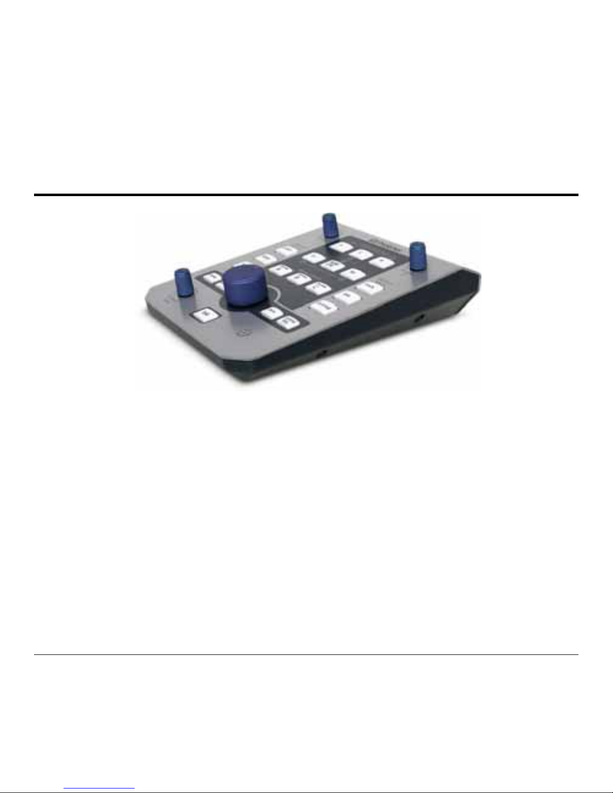
Thank you for purchasing the PreSonus Monitor Station Remote. PreSonus Audio Electronics
has designed the Monitor Station Remote utilizing high-gr ade components to insure optimum
performance that will last a lifetime.
The Monitor Stati on Remote (MSR) for the F ireStudio is a complete s urround/stereo spea ker
manager, input switcher and communication system delivering a more efficient work flow. The
Monitor Station Rem ote connects to the FireStudio via s tandard Cat 5 Ethernet cable t o keep
your work space as clean as possible. Ther e are also two he adphone out puts on the FireS tudio
for even further flexibility and conv enience.
We suggest you use this m anual to familiarize yo urself with the features, applications and
correct connection procedure for your Monitor Station Remote before trying to connect it to
your computer. This will hopefully alleviate any unforeseen issues y ou may encounter during
setup and use.
Page 6
1.2 WHAT IS IN THE BOX
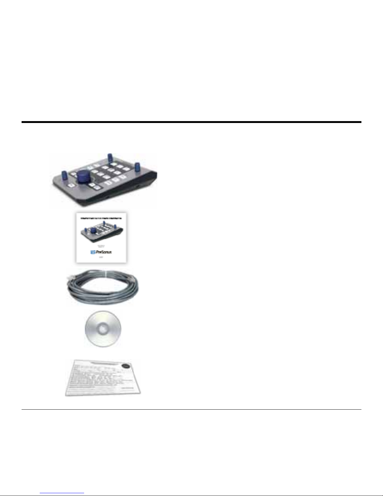
Your Monitor Station Remote
p
OVERVIEW
2
ackage contains the followi ng:
• Monitor Station Re
m
• Monitor Station Re
m
• 20’ Ethernet cable
(
• Monitor Station Re
m
Installation disc
• Warranty Card
ote
ote User’s Manual v1.0
Cat5/RJ45)
ote
Page 7

OVERVIEW
3
1.3 SYSTEM REQUIREMENTS
The Monitor Stat ion Remote enhances the feat ures of the FireStudio and its Control Console
software. You will need a FireStudio and a computer meeting the minimum system
requirements of th e Fir e Studio:
Windows
• OS:
Microsoft Windows X P Home or Professional (Service Pack 1 or later) .
• Computer:
Windows compatible computer with FireWire 400 port (IEEE 1394a).
• CPU/Clock:
Pentium/Athlon 1.6 GHz or faster.
• Memory (RAM):
512 MB (1GB+ recommended).
• Monitor / Display:
1024 x 768 pixels or greater.
Macintosh
• OS:
Mac OS X v10.4.x
• Computer:
Apple Macintosh series with FireWire 400 port (IEEE 1394a).
• CPU/Clock:
PowerPC G4/Dual 1GHz or faster; All Intel-based Mac models.
• Memory (RAM):
512 MB (1GB+ recommended).
• Monitor / Display:
1024 x 768 pixels or greater.
Page 8

OVERVIEW
4
1.4 INSTALLATION GUIDE
1.4.1 Quick Start Guide
The
Monitor Stat ion Remote Installation
disc included wit h your Monitor Station R emote
is the same installation disc included with the FireStudio. (These installation files are also
downloadable fr om our Web site at www.PreSonus.com
.)
Before connecting your Monitor Station Remote to your FireStudio, you must install the
latest drivers and software for your FireStudio. It is very likely you already completed
these steps during your FireStudio installation. If you meet the following conditions, you
can skip to “Hardware Installation” an d begin using your M onitor Station Remote:
9 You have already installed your FireStudio.
9 The version number of the FireStudio Installation Drivers disc used to install your
FireStudio is current wit h or later than the version number of the Monitor Station
Remote Installation disc included with y our Monitor Station Remote.
9 The FireStudio Control Console Hardware Settings tab includes a section labeled
“MSR Settings”.
Hardware Installation
1) Connect one end of the s upplied Ethernet c able to the
Remote Control Input
jack on
your FireStudio’s rear panel.
2) Connect the other end of the supplied Ethernet cable to the
Remote
input jack on
your Monitor Station Remote’s rear panel.
The lights on your Monitor Station
Remote should flash during this step.
3)
See “3 Sample Hookup Diagrams” for help with your speaker connections.
Page 9

OVERVIEW
5
1.4.2 Software and Hardware Installation
IMPORTANT: If you are installing your FireStudio and Monitor Station Remote
concurrently, do not use the FireStudio Installation Drivers Disc v1.0.1
. Otherwise,
completely uninstall the prior installation and use only the FireStudio Control Console
software installed with your Monitor Station Remote Installation Disc via the steps below.
Before connecting your Monitor Station Remote to your FireStudio, insert the Monitor
Station Remote I nstallation Di sc into y our com puter and f ollow t hese instru ctions to i nstal l
updated FireStudio drivers and softw ar e:
Windows Software Installation
1) Browse the disc and r un ”FireStudio_MSR _I nstaller
.exe
”.
2) Run “Firmware Updater” from the Start Menu folder,
PreSonus Drivers
.
Macintosh Softwar e I nstallation
1) Browse the disc and r un “FireStudio Installer .pkg”.
2) Run “FireStudio Firmware Updater” from the
Applications
folder.
Hardware Installation
3) Connect one end of the supplied Ethernet cable to the
Remote Control Input
connection on yo ur FireStudio’s rear panel.
4) Connect the other end of the s upplied Etherne t cable to the
Remote
input connection
on your Monitor Station Remote’s rear panel.
The lights on the Monitor Station
Remote should flash during this step.
5)
See “3 Sample Hookup Diagrams” for help with speaker connections.
Page 10
OVERVIEW
6
1.5 PANEL LAYOUT AND OPERATION
1.5.1 Top Panel
Page 11

OVERVIEW
7
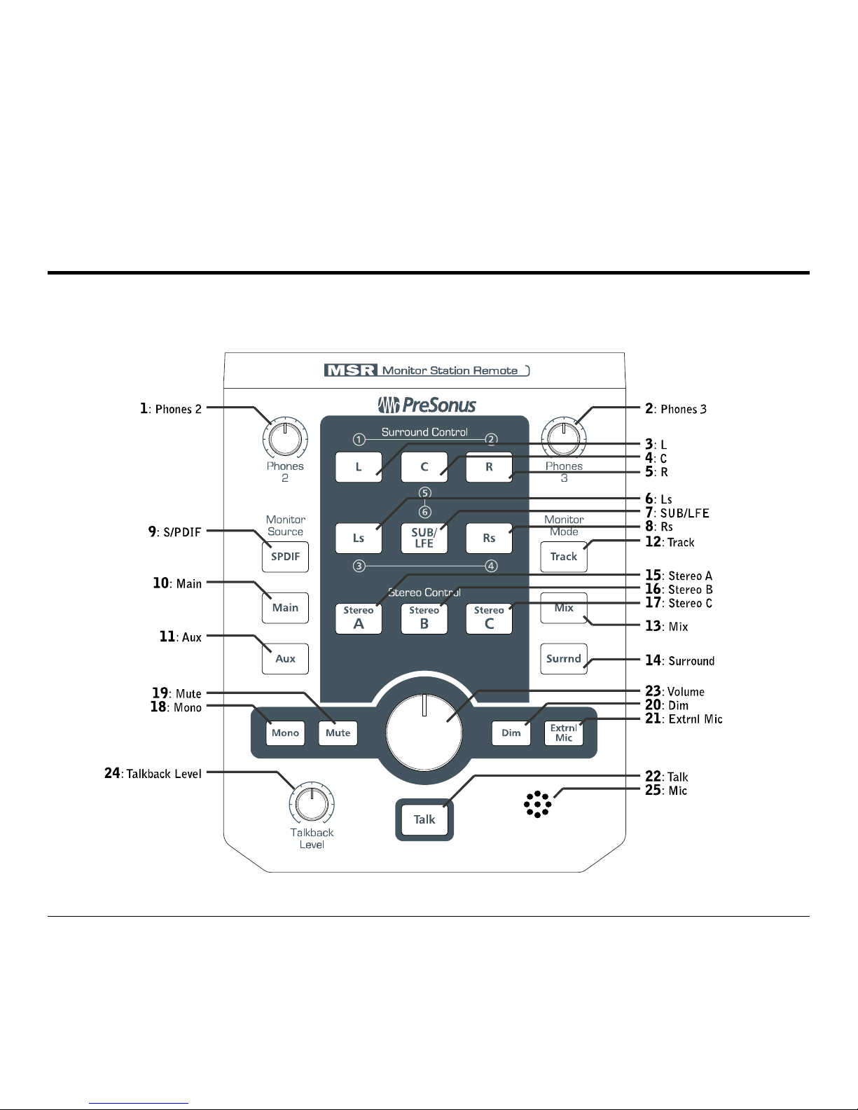
Headphone Control Knobs
1. Phones 2
Controls headphone 2 output volume.
2. Phones 3
Controls headphone 3 output volume.
Surround Control Buttons
(Surround mode only)
Pressing an active Surround Control button will deactivate it.
3. [L]
(De)Activates Left front speaker (output 1) .
4. [C]
(De)Activates Center front speaker (output 5).
5. [R]
(De)Activates Right front speaker (output 2).
6. [Ls]
(De)Activates Left surround speaker (output 3).
7. [SUB/LFE]
(De)Activates Subwoofer/Low Frequency Effects speaker (output 6).
8. [Rs]
(De)Activates Right surround speaker (output 4 ).
Monitor Source Selection Buttons
(Track & Mix modes)
9. [SPDIF]
Routes the S/PDIF input to active Speaker outputs on the FireStudio.
10. [Main]
Gives the FireStudio Control Console control of the active S peakers’ source.
11. [Aux]
Routes DAW Aux input to active Speaker outputs on the FireStudio.
Page 12

OVERVIEW
8
Monitor Mode Selecti o n Buttons
12. [Track]
Puts the FireStudio in Track mode.
The FireStudio outputs are controlled by the FireStudio Control Console, allowing
up to nine stereo mixe s out of the FireStudio’s outputs.
13. [Mix]
Puts the FireStudio in Mix mode.
General purpose outputs 5-8 and Main Outs L/R are reserved for Stereo Speaker
Sets A, B & C and ar e dis abl ed in th e Fire St udi o C on tr ol Co nsol e. Al l o ther o utp uts
are controlled by the FireStudio Control Cons ole as in Track mode.
14. [Surrnd]
Puts the FireStudio in Surround mode.
General purpose outputs 1-6 and Main Outs L/R
(see 1.5.3)
are reserved for
Surround Speaker Contr ol and are disabled in the FireStudio Contr ol Console. All
other outputs are controlled by the FireStudio Control Console as in Track mode.
Stereo Control As signment Buttons (Mix mode only)
15. [Stereo A]
Activates speaker set A (Main Outs L/R) and deactivates Speaker set B.
16. [Stereo B]
Activates speaker set B (outputs 7/8) and deactivates Speaker set A.
17. [Stereo C
] (De)Activates speaker set C (outputs 5/6).
Page 13

OVERVIEW
9
Master Controls
18. [Mono]
Switches Main Outs from stereo to a mono sum
(Track & Mix modes).
19. [Mute]
Mutes all active speakers.
20. [Dim]
Attenuates (reduces) the vo lume of all active speakers by -20dB.
21. [Extrnl Mic]
(De)Activates the ext er nal microphone XLR inp ut on the Monitor
Station Remote and deactivates the internal talkback level knob & microphone.
22. [Talk]
(De)Activates talkback microphone.
Momentary talkbac k activation
- Pressing and holding the Talk butt on will activate
the talkback microphone only while the Talk button is depressed.
Latching the talkback mic
- Pressing the Talk button and immediately releasing it
will activate the talkback microphone until the Talk button is pressed again.
23. Main Volume
Controls the volume of active speaker set.
The Monitor Station
Remote Main Volume control overrides the FireStudio’s Main Level knob.
24. Talkback Level
Controls the volume level of the active talkback microphone.
25. Microphone
Internal talkbac k microphone.
Page 14
OVERVIEW
10
1.5.2 Rear Panel
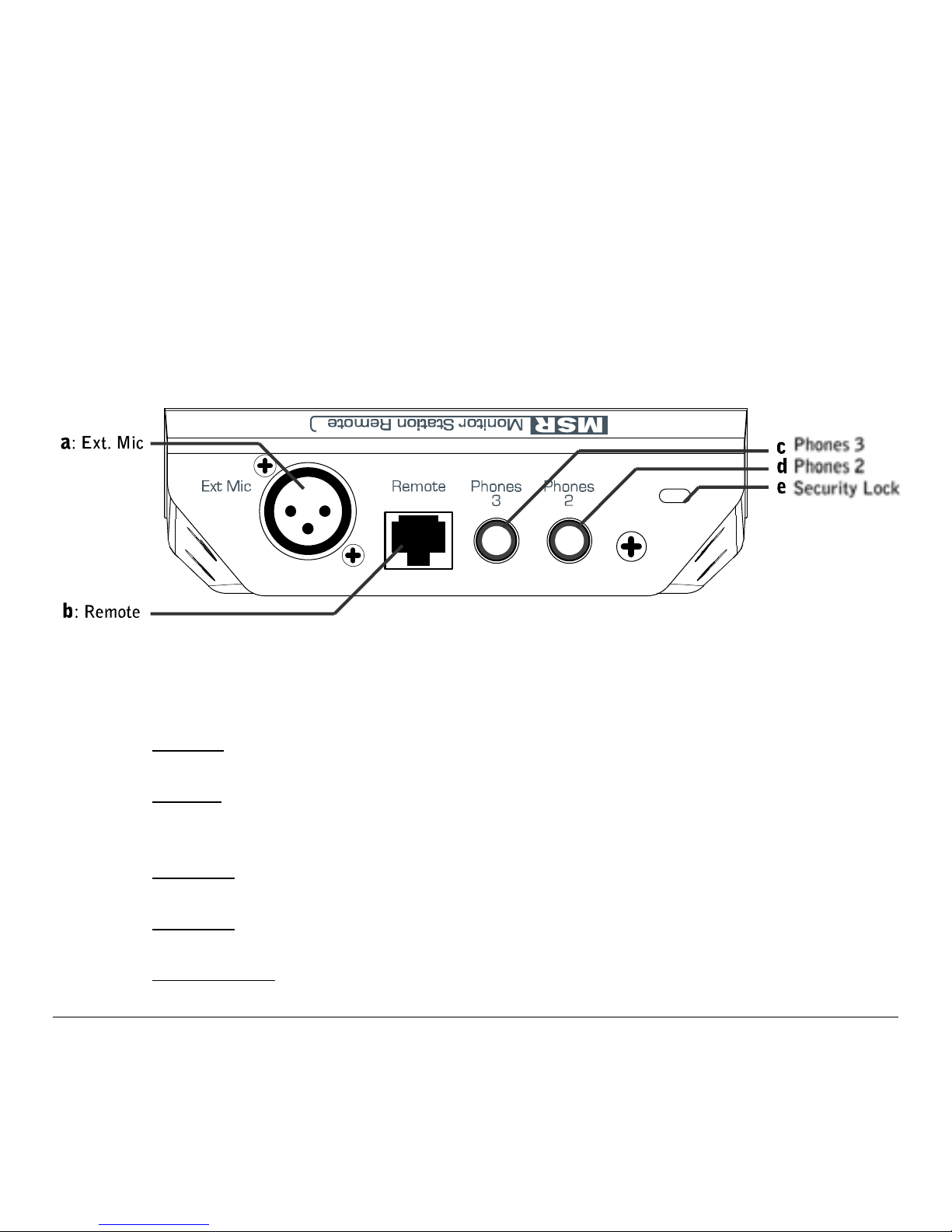
a. Ext Mic
Connects a dyna mic microphone for use as an external talkback mic.
b. Remote
Connects your Monitor Station Remote and Fir eStudio via the included
standard Ethernet cable ( Cat5/RJ45).
c. Phones 3
Stereo ¼” output for headphone 3.
d. Phones 2
Stereo ¼” output for headphone 2.
e. Security Lock
Connects a lock sys tem to your Monitor Station Remote.
Page 15

OVERVIEW
11
1.5.3 FireStudio Control Console
*
1. Copy 1/2 to main L/R in surround mode
Copies Daw 1 & Daw 2 output streams to
Main Out L/R when in Surround mode. Disabling this option will mute the Main
L/R outputs in surround mode.
This enables you to use your surround speaker
setup’s Left front and Right front speakers for stereo mixing in Track o r Mix mode.
2. Talkback to Di gital Outs
Sends the talkback microphone to ADAT 1-8 and S/PDIF
L/R outputs in additio n to Analogue 1-8 and Phones 1-3.
*
More detailed inform ation concerning the FireS tudio Control Console and its use can
be found in your FireStudio User’s Manual. The FireStudio User’s Manual is
downloadabl e fr om our Web site at www.PreSonus.com
.
Page 16
MONITOR MODES
12
2.1 TRACK MODE
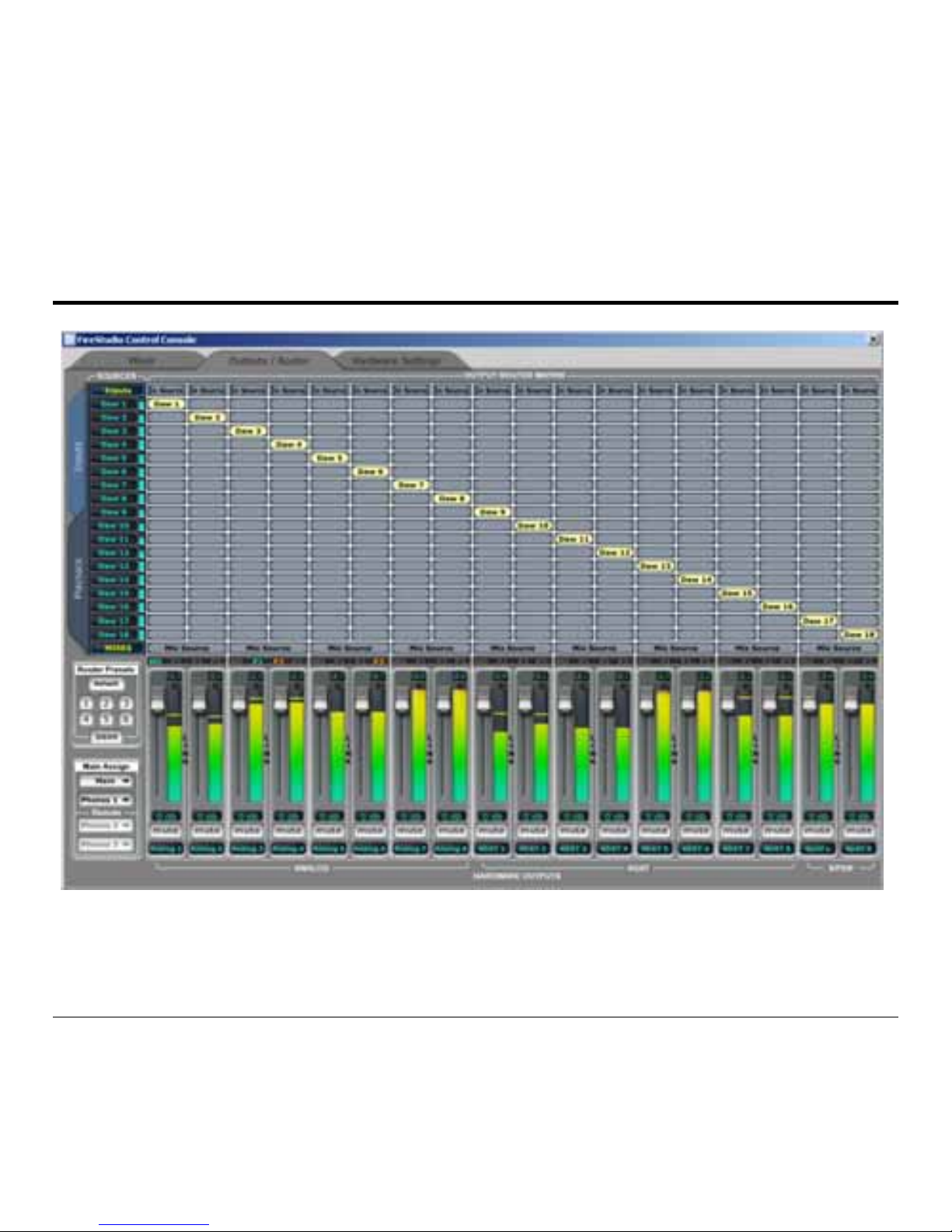
Track mode is typically use d during the tracking / rec ording stage of your proje ct – especially
when the FireStudi o Control Console is bein g us ed for creating mixes or for i/o routing.
Page 17

MONITOR MODES
13
Track mode allows the Fir eStudio Control Co ns ole to maintain full co ntrol over the
FireStudio’s input and output routing.
The FireStudio Control Console Mixer
*
enables you to create and route up to nine zero-latency
mixes; its Output Router Matrix enables you to route the FireStudio’s inputs directly to its
outputs in virtually any configuratio n to suit a variety of applic ations.
Additional features to the FireStudio Control Console when set to Track mode include the
Monitor Source, Master Co ntrols and headphone o ut pu ts 2 & 3.
Monitor Source
Press the Monitor So urce buttons on the Monit or Station Remote to ch ange the source of the
Main Outs when in Mix Mode.
Track mode offers thr ee different source options:
• S/PDIF
Routes only the FireStudio’s S/PDIF input to the Active Outputs.
• Main
The FireStudio Contr ol Console determines the source of the Active Outp uts.
• Auxiliary
Routes only the FireStudio’s Auxiliary RCA inputs to the Active Outputs.
*
More detailed information concerning the FireStudio Control Console and its use can be
found in your FireStudio User’s Manual. The FireStudio User’s Manual is downloadable
from our Web site at www.PreSonus.com
Page 18
MONITOR MODES
14
2.2 MIX MODE
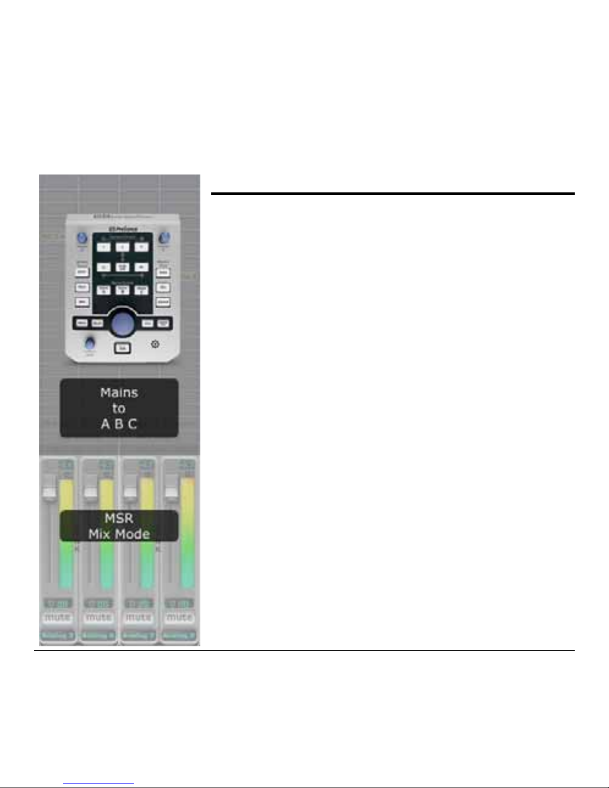
As its name implies, Mix mode is typically used during the
Mixing stage of your project – especially when you have
multiple sets of monitors to reference your mix on (i.e.,
Nearfields & Mains).
Mix mode enables the [Stereo A], [Stereo B] & [Stereo C]
Stereo Control buttons on the Monitor Stati on Remote and puts
the FireStudio in Mix mode – allowing you to toggle your
output between different speak er set s.
General purpose outputs 5-8 are reserved for Stereo Control
and are disabled in the Fir eStudio Control Cons ole
as shown in
the screenshot image at left
.
The Main Level control knob on the Monitor Station Remote
controls the volume level of all active Speaker sets equally
when the FireStudio is in Mix mode.
Outputs 1-4, Main L/R, ADAT, S/PDIF & Phones 1-3 function
as in Track mode.
Page 19

MONITOR MODES
15
Monitor Source
Press the Monitor So urce buttons on the Monit or Station Remote to ch ange the source of the
active stereo Speaker sets when in Mix Mode.
Mix mode offers three di ffer ent source options :
• S/PDIF
Routes only the FireStudio’s S/PDIF input to the Active Outputs.
• Main
The FireStudio Contr ol Console determines the source of the Active Outp uts.
• Auxiliary
Routes only the FireStudio’s Auxiliary RCA inputs to the Active Outputs.
Stereo Control
Press the Stereo Control buttons on the Monitor Station Remote to toggle the active Stereo
outputs between thr ee s ets of stereo outputs:
• [Stereo A]
Corresponds to the FireStudio’s Main Outs L/R.
• [Stereo B]
Corresponds to the FireStudio’s general purpose outputs 7/8.
• [Stereo C
] Corresponds to the FireStudio’s general purpose outputs 5/6.
Stereo A and B cannot be on simultaneously. Stereo C can be on at all times in Mix mode.
Typical use for St ereo A and B is nearfield r eference monitors on Stereo A a nd larger s tudio
monitors on Stereo B. Typical use for Stereo C is a subwoofer .
Page 20
MONITOR MODES
16
2.3 SURROUND MODE
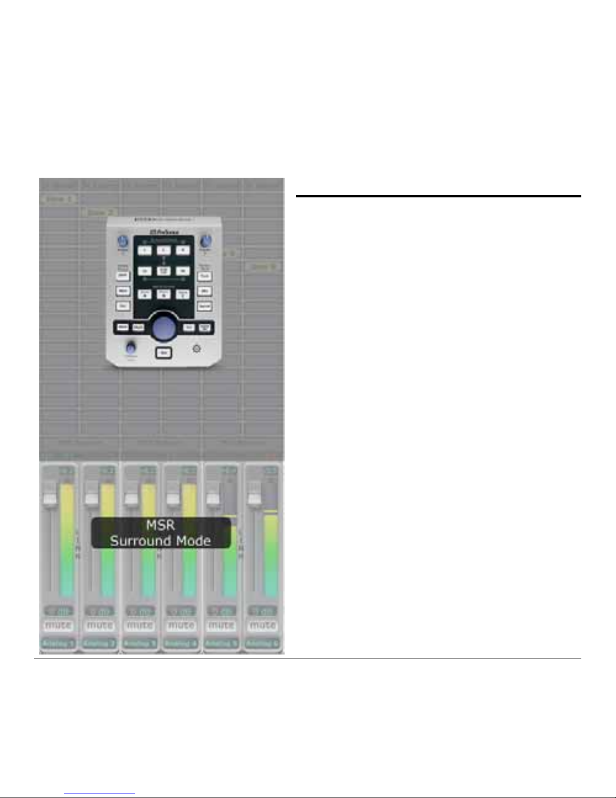
As its name implies, Surround mode is typically
used for Surround Sound Mixing sessions.
Surround mode enables the [L], [C], [R], [Ls],
[SUB/LFE] & [Rs] Surround Control buttons on
the Monitor Station Remote and puts the
FireStudio in Surround mode.
General purpose outputs 1-6 and Main L/R are
reserved for Surround Control and are disabled
in the FireStudio Control Console
as shown in
the screenshot image at left
– output streams
Daw 1 through Daw 6 route directly to general
purpose outputs 1-6 & Main L/R.
The Main Level control knob on the Monitor
Station Remote controls the volume level of all
active Surround outputs equally when the
FireStudio is in Surround mode.
Outputs 7/8, ADAT, S/PDIF & Phones 1-3
function as in Track mode.
Page 21

MONITOR MODES
17
Surround Control
Press the Surround Control buttons on the Monitor Station Remote to activate or de activate
the corresponding Surround speaker output when in Su rround Mode:
• [L] (Left front)
Daw 1 output stream.
Corresponds to general purpose output 1 and Main Out L
(1.4.3)
• [C] (Center front) Daw 5 output stream.
Corresponds to general purpose output 5.
• [R] (Right front)
Daw 2 output stream
Corresponds to general purpose output 2 and Main Out R
(1.4.3).
• [Ls] (Left surround)
Daw 3 output stream.
Corresponds to general purpose output 3
• [SUB/LFE] (Subwoofer/Low Frequency Effects)
Daw 6 output stream.
Corresponds to general purpose output 6.
• [Rs] (Right surround)
Daw 4 output stream.
Corresponds to general purpose output 4.
The Main Level control knob on the Monitor Station Remote controls the volume level of all
active Surround outputs equally when the FireStudio is in Sur round mode.
Page 22

SAMPLE HOOKUP DIAGRAMS
18
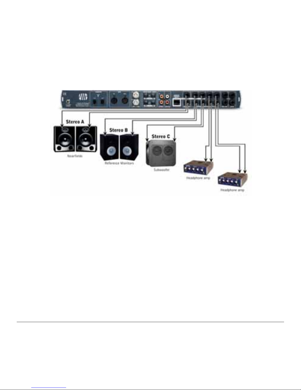
3.1 STEREO RECORDING & MIXING ENVIRONMENT
**
This setup is for studios mixing and tracking exclusively in stereo.
Connect nearfield reference monitors to Main Outs L/R (Speaker A). Connect larger studio
mains (or another set of reference monitors) to general purpose outputs 7/8 (Speaker B).
Connect a subwoofer to general purpose outp uts 5/6 (Speaker C).
Connect external stereo devices such as a CD/Cassette dec k or Stereo to the Fire Stu dio S/PDIF
input. Connect devices s uch as a portable mp3 player to the Auxiliary RCA input.
Connect headphone distribution amplifiers, such as the HP4, to general purpose outputs 1/2 &
3/4 for use with the FireStudio C ontrol Console Mixer.
If you need more dedicated headphone outputs for monitor mixes, you can:
1. Use Phones 1 on the front of the FireStudio.
2. Use Phones 2 & 3 on the Monitor Station Remote.
3. Connect a DigiMax FS via ADAT for more routing options.
(see 3.3)
**
Your speaker configuration is not limited to the sample hookup diagrams presented here.
The hookup diagrams in this manual are meant to assist you – not to restrict you. For
example, if you have speakers with S/PDI F input or a 2.1 stereo speaker setup with in ternal
crossovers and subwoofer level, then your setup will vary accordingly.
Please consult your har dware user’s manuals for more informati on in cases such as this.
Page 23
SAMPLE HOOKUP DIAGRAMS
19
Page 24

SAMPLE HOOKUP DIAGRAMS
20
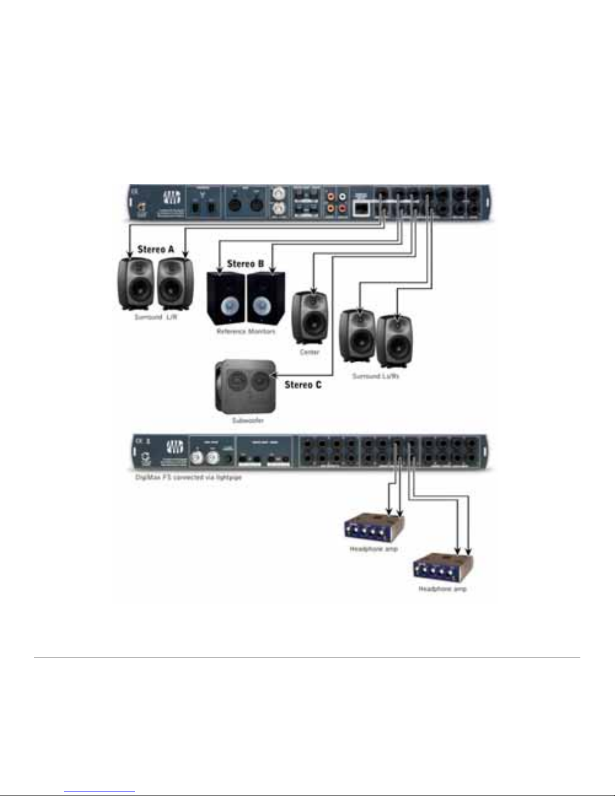
3.2 STEREO AND SURROUND MIXING ENVIRONMENT
This setup is for studios dedicated to stereo and surround mixing. Any possible tracking
sessions use Phone s 1, 2 or 3 or do not require dedicated headphone mo nitor mixes.
Connect Surround L/R Front monitors doubling as stereo nearfield reference monitors to
FireStudio Main Outs L/R (Speaker A). Connect dedicated Surround L/R Front monitors to
general purpose outputs 1/2 and dedicated nearfield reference monitors to Main Outs L/R.
Connect larger st udio mains (or a nother set of refer ence monitors) to general purpose outputs
7/8 (Speaker B).
Be sure to uncheck “Copy 1/2 to main L/R in surround mode” in the FireStudio Control
Console MSR Settings
(see 1.5.3)
when using dedicated Surround & Stereo L/R monitors .
Connect Surround Ls/Rs monitors to general purpose outputs 3/4. Connect the Surround
Center monitor to gener al purpose output 5. Connect the Surroun d Subwoofer/L ow Frequency
Effects speaker to general purpose output 6.
Connect external stereo devices such as a CD/Cassette dec k or Stereo to the Fire Stu dio S/PDIF
input. Connect devices s uch as a portable mp3 player to the Auxiliary RCA input.
Connect headphone distribution amplifiers, such as the HP4, to general purpose outputs 1/2 &
3/4 for use with the FireStudio C ontrol Console Mixer.
If you need more dedicated headphone outputs for monitor mixes, you can:
1. Use Phones 1 on the front of the FireStudio.
2. Use Phones 2 & 3 on the Monitor Station Remote.
3. Connect a DigiMax FS via ADAT for more routing options.
(see 3.3)
Page 25

SAMPLE HOOKUP DIAGRAMS
21
Page 26

SAMPLE HOOKUP DIAGRAMS
22
3.3 EXPANDED 2.1 AND 5.1 RECORDING & MIXING ENVIRONMENT W/ DIGIMAX FS
This setup is for studios tackling stereo and surround mixing sessions as well as frequent
tracking sessio ns r e quiring dedicated headphone monitor mixes in the studio.
Connect your contr ol r oo m monitors as describ e d in 3.2.
Connect the ADAT inputs of your DigiMax FS
***
to the FireStudio’s ADAT outputs. Connect
headphone distributi on amplifiers, such as the HP4, to the DigiM ax FS DAC outputs 1-8 for
use with the FireStudio Co ntrol Console Mixer.
Be sure to check “Tal kback to Digital O uts” in the Fir eStudio Control Console MSR Se ttings
(see 1.5.3)
when using the FireStudio’s ADAT outputs for headphone mixes.
*** For more information on the DigiMax FS or the FireStudio’s ADAT capabilities, please
consult the User’s Manual or visit our Web si te at www.PreSonus.com
.
Page 27
SAMPLE HOOKUP DIAGRAMS
23
Page 28

TECHNICAL INFORMATION
24
4.1 SPECIFICATIONS
Physical
Package Type ..................................................................................... PVC and Steel Chassis
Dimensions .............................................................. 7" x 5.25" x 1.75" (18cm x 13cm x 4cm)
Weight ................................................................................................... Approximately 1 lb.
Dynamic Microphone Input
Type .................................................................................................. XLR Female Balanced
Input Impedance ........................................................................................................ 1200Ω
Internal Microphone
Type .......................................................................................................... Electret Condenser
Sensitivity .................................................................................................................. -45 dB
Headphone Audio Outputs
Type .................................................................................................... ¼” TRS Active Stereo
Maximum Output .................................................................... 150mW/channel @ 75Ω Load
THD+N .................................................................. ≤ 0.04% (150mW/channel @ 75Ω Load)
Frequency Response ............................................................................ 10Hz – 10kHz, ± 1dB
As a commitment to constant improvement, PreSonus Audio Electronics, Inc. reserves the
right to change any specification stated herein at any time in the future without notification.
Page 29

TECHNICAL INFORMATION
25
4.2 TROUBLESHOOTING
PreSonus will only provide support for issues directly related to your M onitor Station Remote.
PreSonus does not provide support for issues regarding operating systems or additional
hardware & software. I t may be necessary to contact the computer, oper ating system and/or
software manufac tur er to obtain additional technical support.
For technical assistance, visit our Web site at www.PreSonus.com
, call us at 225.216.7887
between 9am and 6p m CST (GMT -06:00) or e-mail us at [email protected]
.
Before contacting technical support for your Monitor Station Re mote, please try the follow ing:
1) Check our Web site at www.PreSonus.com
for possible updates to your FireStudio,
Monitor Station Remote and FireStudio Control Console so ftw are.
2) Disconnect and re connect your Monitor Station Remote.
3) Check your Ethernet cable and/or try a dif fer ent Ethernet cable.
When contacting technical support, please have the following infor mation at hand:
¾ What Operat ing System and version (ex; Mac OS X 10.4.7) you are running.
¾ The Firmware, FPGA and Software Version number of your FireStudio and FireStudio
Control Console
(from the FireStudio Control Console Hardware Settings).
¾ Your Monitor Station Remot e serial number
(located on the bottom of your unit)
.
4.2.1 Software and Firmware Updates
PreSonus may periodically release updates to enhance your Monitor Station Remote and
FireStudio functionality. Please check our Web site, www.PreSonus.com
, regularly for
software, firmware & information updates and for technical s upport.
Page 30

 Loading...