

Page 1
FIRESTUDIO
26 I/O 24-bit/96 kHz Recording Interface
User’s Manual
Version 3.0
© 2009, PreSonus Audio Electronics, Inc.
All Rights Reserved.
Page 2

PRESONUS LIMITED WARRANTY
PreSonus Audio Electronics Inc. warrants this product to be free of defects in material and workmanship for a
period of one year from the date of original retail purchase. This warranty is enforceable only by the original
retail purchaser. To be protected by this warranty, the purchaser must complete and return the enclosed
warranty card within 14 days of purchase. During the warranty period, PreSonus shall, at its sole and absolute
option, repair or replace, free of charge, any product that proves to be defective on inspection by PreSonus or its
authorized service represen t ative. To obtain warranty service, the purchaser must first call or write PreSonus at
the address and telephone number printed below to obtain a Return Authorization Number and instructions
about where to return the unit for service. All inquiries must be accompanied by a description of the problem. All
authorized returns must be sent to the PreSonus repair facility postage prepaid, insured, and properly packaged.
PreSonus reserves the right to update any unit returned for repair. PreSonus reserves the right to change or
improve the design of the product at any time without prior notice. This warranty does not cover claims for
damage due to abuse, neglect, alteration, or attempted repair by unauthorized personnel and is limited to
failures arising during normal use that are due to defects in material or workmanship in the product. Any
implied warranties, including implied warranties of merchantability and fitness for a particular purpose, are
limited in duration to the length of this limited warranty. Some states do not allow limitations on how long an
implied warranty lasts, so the above limitation may not apply to you. In no event will PreSonus be liable for
incidental, consequential, or other damages resulting from the breach of any express or implied warranty,
including, among other things, damage to property, damage based on inconvenience or on loss of use of the
product, and, to the extent permitted by law, damages for personal injury. Some states do not allow the
exclusion of limitation of incidental or consequential damages, so the above limitation or exclusion may not
apply to you. This warranty gives you specific legal rights, and you may also have other rights, which vary from
state to state. This warranty only applies to products sold and used in the United States of America. For
warranty information in all other countries please refer to your local distributor.
PreSonus Audio Electronics, Inc.
7257 Florida Blvd.
Baton Rouge, LA 70806
www.PreSonus.com
© 2009, PreSonus Audio Electronics, Inc.
All Rights Reserved.
Page 3

SAFE OPERATION GUIDELINES
To avoid damage to your FireStudio and your other audio equipment please review and adhere to the following
safety guidelines:
Follow the safety guidelines in the manual.
Do not drop your FireStudio.
Do not install the unit near a heat source (radiators, heat registers, ampl ifi er heat sinks , etc.).
Do not expose your FireStudio to liquids. Do not place containers filled with liquids near your
FireStudio.
Do not allow dust particles to collect in excess on your FireStudio. Keeping the unit covered
when not in use is highly recommended and will extend the life of your product.
Protect the power supply and its cord from being walked on, wheeled over, or pinched. If the
power supply becomes damaged, purchase a new one.
Unplug your FireStudio when not in use for long periods of time and during electrical storms,
hurricanes, tornadoes, and other extreme weather.
Use only the attachments/accessories recommended or manufactured by PreSonus for your
FireStudio.
All domestic PreSonus products should be serviced at the PreSonus factory in Baton Rouge,
Louisiana. If your FireStudio requires a repair, contact techsupport@presonus.com to arrange
for a return-authorization number. Customers outside the U.S. should contact their local
distributor. Your distributor’s contact information is available at www.presonus.com
Page 4

TABLE OF CONTENTS
1 OVERVIEW
1.1 Introduction ............................................................................................................................................................. 3
1.2 Features .................................................................................................................................................................. 4
1.3 What is in the Box ................................................................................................................................................... 5
1.4 System Requirements ............................................................................................................................................... 6
2 GETTING STARTED
2.1 Hardware Installation .............................................................................................................................................. 7
2.1.1 Installation in Microsoft Windows .................................................................................................................... 7
2.1.2 Installation in Mac OS X .................................................................................................................................. 7
2.2 Studio One Artist ..................................................................................................................................................... 8
2.2.1 Installation and Authorization ............................................................................................................................ 8
2.2.2 Enabling the FireStudio Driver ........................................................................................................................... 9
2.2.3 Configuring Your External MIDI Devices .......................................................................................................... 10
2.2.4 Configuring Your Audio I/O .............................................................................................................................. 13
2.2.5 Creating a New Song ....................................................................................................................................... 14
2.2.6 Cue Mix and the FireStudio ............................................................................................................................. 17
2.2 Sample Hookup Diagrams ...................................................................................................................................... 20
2.2.1 Mobile Recording with the FireStudio and Two DigiMax FS .............................................................................. 20
2.2.2 Full Band Set-up Using the MSR in Track Mode ............................................................................................... 21
3 CONTROLS AND CONNECTIONS
3.1 Universal Control and the FireStudio ...................................................................................................................... 22
3.1.1 Universal Control Console Application Icon .................................................................................................... 22
3.1.2 Launch Window ............................................................................................................................................... 23
3.1.3 WDM Settings (PC only) ................................................................................................................................. 25
3.1.4 The Device Window: Overview .......................................................................................................................... 26
3.1.5 The Device Window: Hardware Settings Tab ..................................................................................................... 26
3.1.6 The Device Window: Outputs/Router Matrix ..................................................................................................... 27
3.1.7 The Device Window: Mixer Tab ....................................................................................................................... 32
3.1.8 The Device Window: Naming Inputs and Outputs............................................................................................... 35
3.2 Front Panel Layout ................................................................................................................................................ 36
3.3 Back Panel Layout ................................................................................................................................................. 38
4 CASCADING UNITS
4.1 Using Multiple Units .............................................................................................................................................. 42
5 TECHNICAL INFORMATION
5.1 Troubleshooting ..................................................................................................................................................... 44
5.2 Specifications ........................................................................................................................................................ 46
Page 5

Page 6
1.1 INTRODUCTION
OVERVIEW
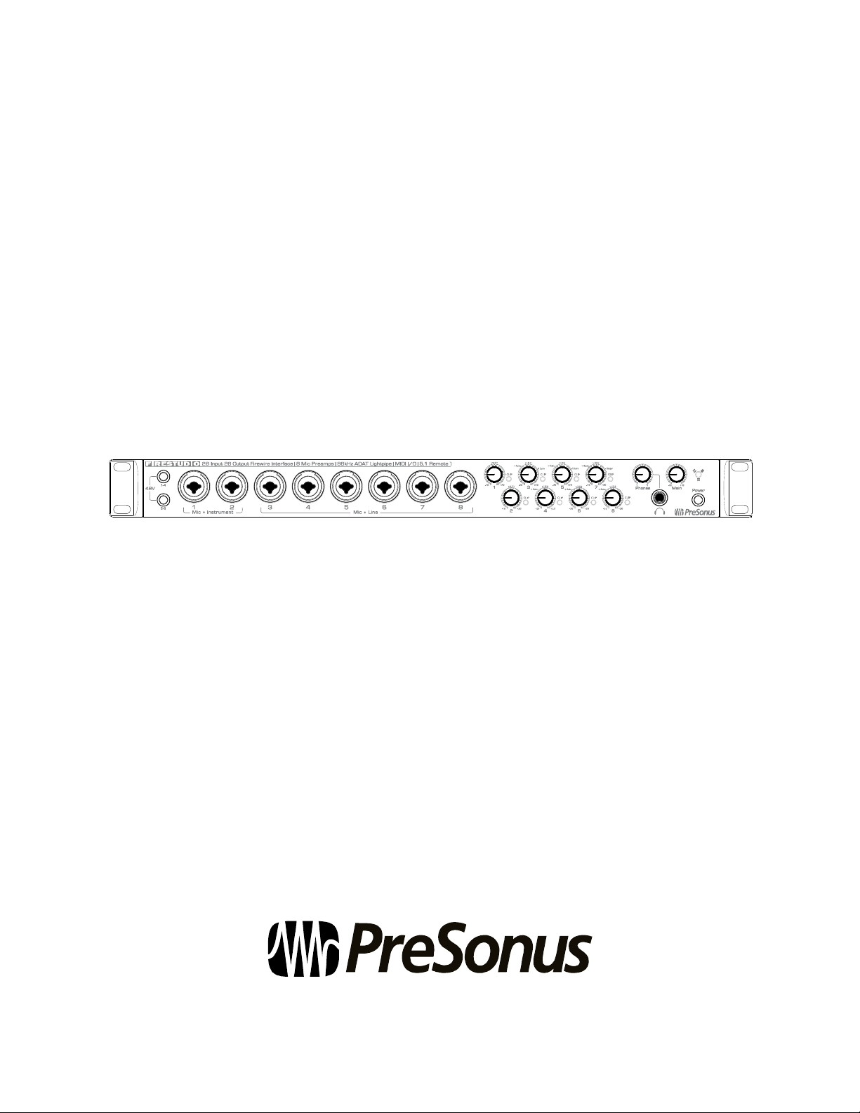
Thank you for purchasing the PreSonus FireStudio. PreSonus Audio Electronics has designed the FireStudio
utilizing high-grade components to ensure optimum performance that will last a lifetime. The FireStudio is
equipped for professional-quality computer recording, with 24-bit, 96 kHz converters; 8 PreSonus XMAX
microphone preamplifiers; Dual SMUX, 96 kHz ADAT; BNC word clock; S/PDIF and MIDI I/O; Universal
Control software; Studio One Artist music-production software; and the optional MSR Monitor Station Remote.
All you need is a computer with a FireWire connection, a few microphones and cables, monitor speakers or
headphones, and your instruments!
PreSonus Audio Electronics is committed to constant product improvement, and we value your suggestions
highly. We encourage you to contact us at 225-216-7887 with questions or comments about your PreSonus
FireStudio. We believe the best way to achieve our goal of constant product improvement is by listening to the
real experts: our customers.
We suggest that you read this manual to familiarize yourself with the features, applications, and connection
procedure for your FireStudio before connecting it to your computer.
Thank you, again, for buying our product. Enjoy your FireStudio!
3 | PreSonus 2008
Page 7

OVERVIEW
1.2 FEATURES
The FireStudio is a powerful and affordable computer recording system. The FireStudio comes equipped with
eight high-quality PreSonus XMAX microphone preamps, MIDI I/O, SPDIF, Dual SMUX 96k ADAT, BNC
word clock and rock solid drivers, as well as a plethora of music recording and production software.
Summary of FireStudio features
High-speed FireWire (IEEE 1394)
24-bit / 96 kHz sampling rate
26 simultaneous inputs and outputs
8 Class A XMAX microphone preamplifiers
2 Insert channels
8 Analog line inputs
2 Instrument inputs
16 Channels of ADAT optical I/O (8 channels via 96k dual S/MUX)
10 balanced TRS outputs
S/PDIF and MIDI I/O
JetPLL jitter control for improved imaging and clarity
High performance A/D D/A converters
OS X and Windows compatible
MSR Monitor Station Remote (Optional)
The FireStudio includes PreSonus Studio One Artist recording software, which comes with over 4 GB of plugins, loops, and samples, giving you everything you need for music recording and production.
Summary of Studio One Artist features
Unlimited track count
Unlimited inserts and sends
20 high-quality native effects plug-ins
o Amp Modeling (Ampire)
o Delay (Beat Delay)
o Distortion (Redlight Distortion)
o Dynamic Processing (Channel Strip, Compressor, Limiter, Tricomp)
o Equalizer (Channel Strip, Pro EQ)
o Modulation (Autofilter, Chorus, Flanger, Phaser, X-Trem)
o Reverbs (MixVerb, Room Reverb)
o Utility (Binaural Pan, Mixtool, Phase Meter, Spectrum Meter, Tuner)
Over 4 GB of loops, samples, and instruments, featuring:
o Presence: Virtual Sample Player
o Impact: Virtual Drum Machine
o SampleOne: Virtual Sampler
o Mojito: Virtual Analog-Modeled Subtractive Synthesizer
Innovative and intuitive MIDI mapping
Powerful dra g -an d- dr op f unctionality for faster workflow
OS X and Windows compatible
4 | PreSonus 2008
Page 8
OVERVIEW
1.3 WHAT IS IN THE BOX
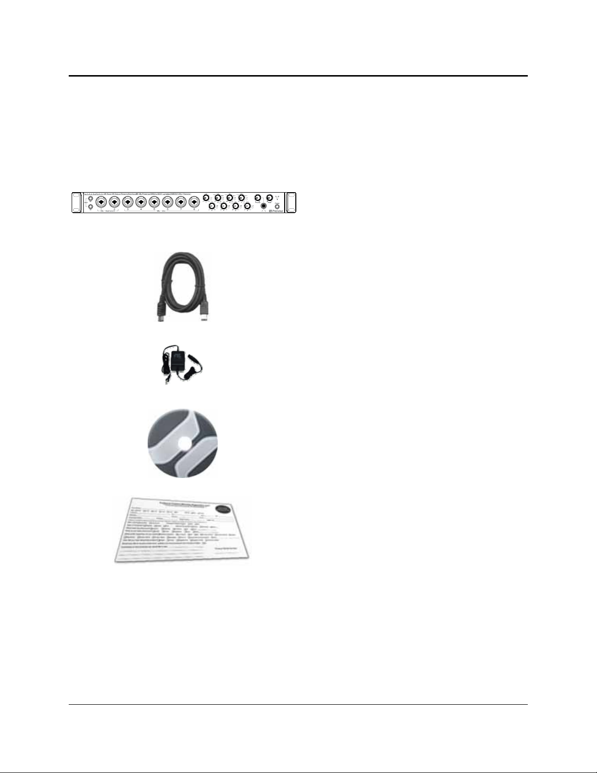
Your FireStudio package contains the following:
FireStudio recording interface
6-foot, 6-pin-to-6-pin FireWire cable
Power supply
Software installation discs:
o PreSonus FireStudio Universal driver
installer
o Studio One Artist installation DVD
PreSonus warranty card
5 | PreSonus 2008
Page 9

OVERVIEW
1.4 SYSTEM REQUIREMENTS
Here are the computer-system requirements for FireStudio and Studio One Artist.
Macintosh
o Operating Systems:
Mac OS X 10.4.11 or Mac OS X 10.5.2 or higher
o Hardware:
Minimum:
PowerPC G4 1.25 GHz or Intel Core Solo 1.5 GHz processor
1 GB RAM
DVD drive
Recommended:
PowerPC G5 or better or Intel Core Duo o r Intel Xeo n process or or be tter
2 GB or more RAM
DVD drive
Windows PC
o Operating Systems:
Windows XP or Vista
o Hardware:
Minimum:
Intel Pentium 4 1.6 GHz processor or AMD Athlon 64 (Turion)
1 GB RAM
DVD drive
Recommended:
Intel Pentium 4 2.8 GHz EM64T or better or AMD Athlon 64 3000+ or
better
2 GB or more RAM
DVD drive
NOTE: The speed of your processor, amount of RAM, and size and speed of your hard drives will greatly affect
the overall performance of your recording system. A more powerful system (faster processor with more RAM)
allows for lower latency (signal delay) and better overall performance.
6 | PreSonus 2008
Page 10

GETTING STARTED
2.1 HARDWARE INSTALLATION
This installer and driver can be used for any interface in the FireStudio family line (FireStudio, FireStudio
Lightpipe, FireStudio Tube, FireStudio Project, FireStudio Mobile and StudioLive 16.4.2). For more
information on the Universal Control application and multiple interface integration, please review Sections 3.1
and 4.1.
2.1.1 Installation in Microsoft Windows
After you insert the installation CD into your CD or DVD drive, th e FireStudio installer will ta ke you th rough
each step of the installation process. Please read each message carefully, ensuring especially that you do not
connect your FireStudio until the installer has finished and you have rebooted your computer.
The FireStudio Installer was designed to be as simple and easy to follow as possible. Please read each
message carefully to ensure that the FireStudio driver is properly installed.
Before continuing the FireStudio Installation Setup, please close all applications and disconnect your
FireStudio from your computer. If you see any Windows Security alerts, click “Install this driver software
anyway” (Vista) or “Continue anyway” (XP).
At the end of the installation, you will be prompted to reboot your computer to complete the installation.
Click “Finish” to automatically restart your PC. Once your computer has rebooted, connect the FireStudio.
When the Found New Hardware wizard launches, follow the recommended steps. When the sync light
remains solid blue, your FireStudio is synced to your computer and is ready to use!
2.1.2 Installation in Mac OS X
After inserting the installation CD into your disc drive, browse the disc and run the FireStudio installer,
which will take you through each step of the installation process. Please read each message carefully,
ensuring especially that you do not connect your FireStudio until the installer has finished and you have
rebooted your computer.
To begin installing the FireStudio driver on your Mac, double click on the FireStudio logo. Th e FireStudio
installer requires that your user password be entered as a security measure. Once you have entered your
password, click “OK” to proceed with the rest of the installation.
When the Installer has fini shed, connect your FireStud io to your computer with a FireWire cable. Once the
sync light is solid blue, your FireStudio is ready to use.
7 | PreSonus 2008
Page 11
GETTING STARTED
2.2 STUDIO ONE ARTIST
Every PreSonus interface comes complete with Studio One Artist recording software. Whether you are about to
record your first album or your 50
th
, Studio One Artist provides you with all the tools necessary to capture and
mix a great performance. As a valued PreSonus customer, you are also eligible for an upgrade discount for
Studio One Pro when you are ready to master your work, create a digital version for the Web, or incorporate
third-party VST plug-ins into your recording process. For more details on the Studio One Pro upgrade program
for PreSonus customers, please visit www.presonus.com
.
2.2.1 Installation and Authorization
Once you have installed the FireStudio drivers and connected your FireStudio, you can use the PreSonus
Studio One Artist music-production software included with your FireStudio to begin recording, mixing, and
producing your music. To install Studio One Artist, insert your installation disc into your computer’s DVD
drive. Follow the onscreen instructions to complete the installation process.
Installing Studio One Artist
To Install Studio One Artist, insert your Studio One Artist installation DVD into
your computer’s DVD drive.
PC Users: Launch the Studio One Artist installer and follow the onscreen
instructions.
Mac Users: Simply drag the Studio One Artist application into the Applications
folder on your Macintosh HD.
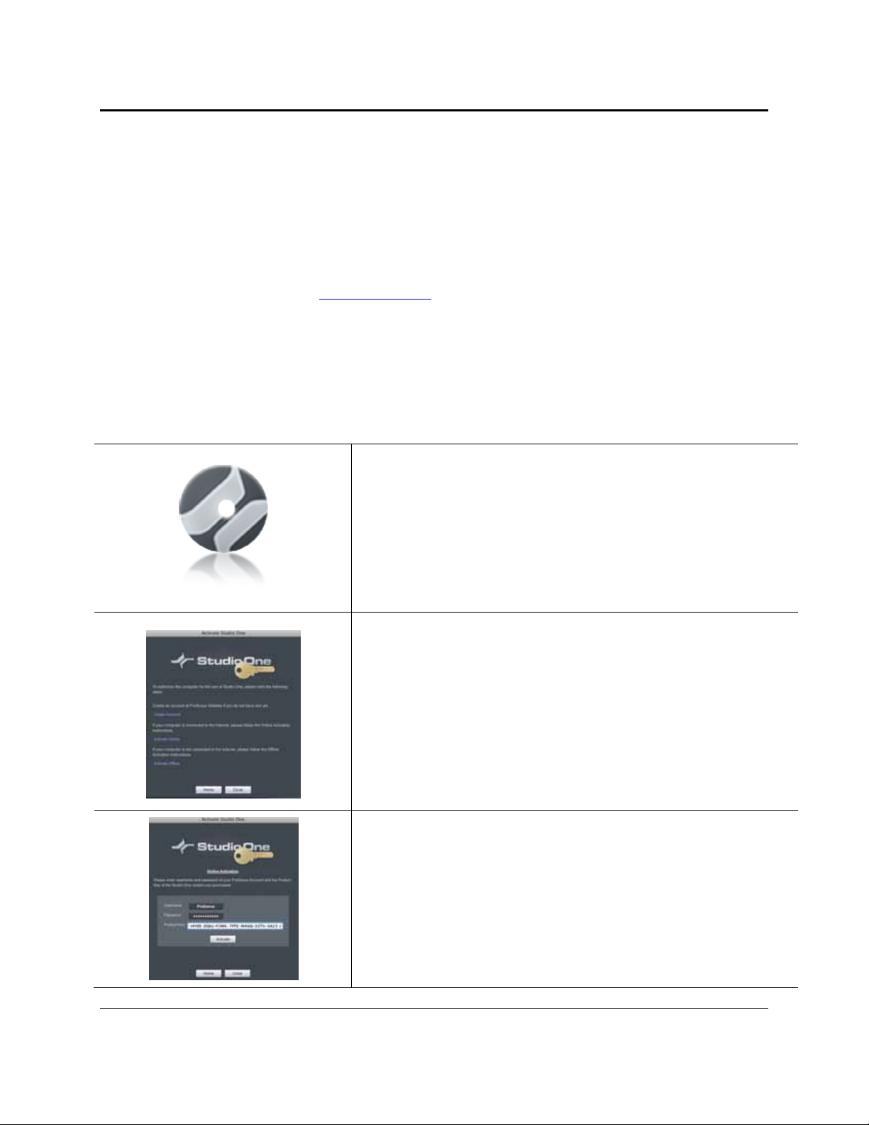
Create a User Account
After installing Studio One Artist, launch the program, and the Activate Studio
One menu will appear. If you are a new Studio One user, you will need to create a
user account. Follow the Create Account link if your computer is connected to the
Internet. Once you have created your account, continue to Activating Studio One
Artist Online.
If your computer is not connected to the Internet, visit the Studio One product
page at www.presonus.com on an Internet-connected computer to create your
account. After you have created your account, skip to Activating Studio One
Artist Offline.
Activating Studio One Artist Online
Now that you have created a user account, you can activate your copy of Studio
One Artist. Launch Studio One Artist, and the Activate Studio One menu will
appear.
Click on the Activate Online link and enter your previously created account
Username, Password, and the Product Key you received with the Studio One
Artist installation disc. Click on the Activate button to finish the activation
process.
8 | PreSonus 2008
Page 12
GETTING STARTED
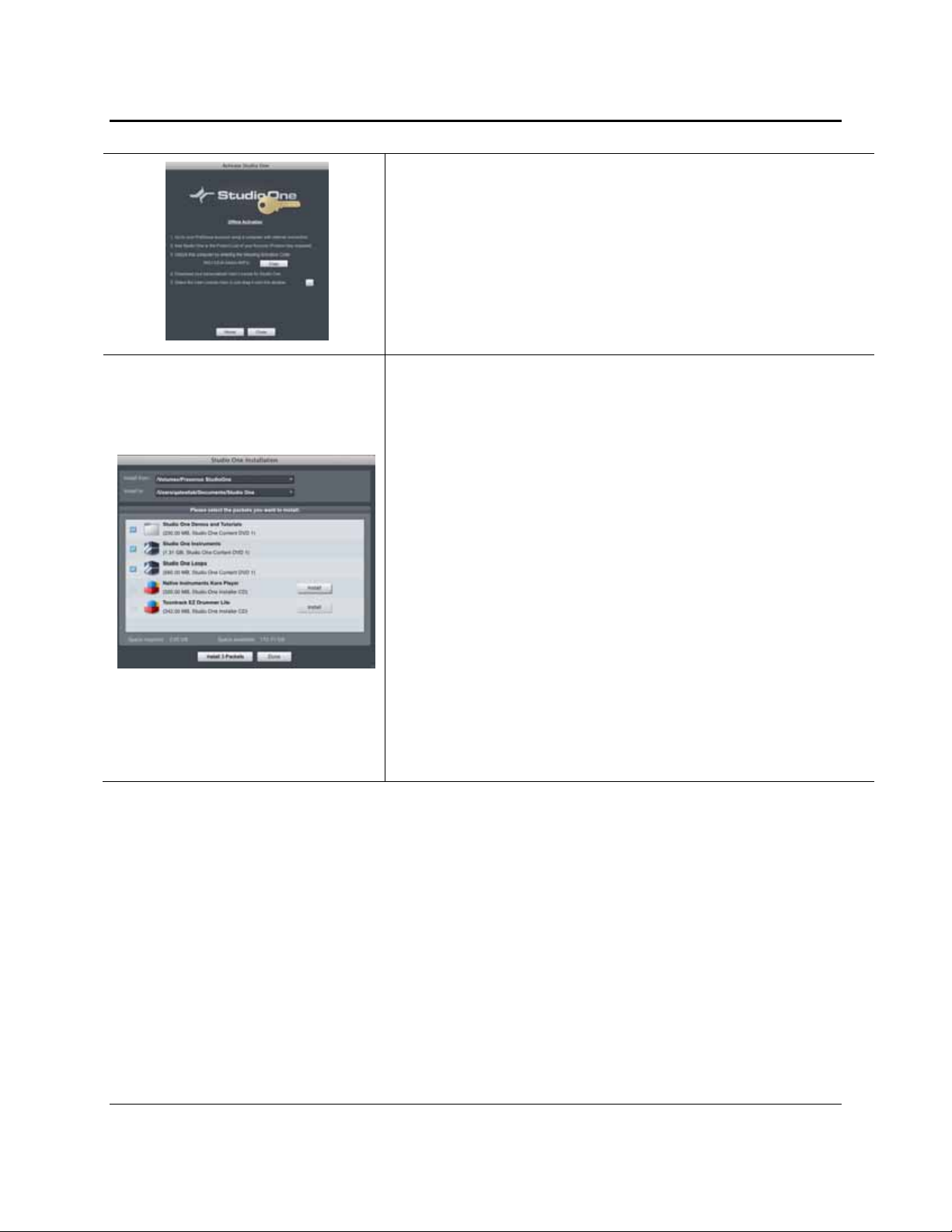
Activating Studio One Artist Offline
Once you have created a user account, launch Studio One Artist. From the
Activate Studio One Menu, click on the Activate Offline link. Follow the
instructions to log in to your previously created user account, register the
product, and obtain a license file.
Next, copy the license file to the computer on which Studio One has been
installed, and locate the license file as instructed in the Activate Studio One
menu. The activation process is now complete.
Installing Bundled Content for Studio One Artist
Studio One Artist comes bundled with an array of demo and tutorial material,
sampled instruments, loops, samples, and unique third-party content. The Studio
One Artist bundle includes all that you need to begin producing music.
Upon completing the Studio One Artist installation and activation process, the
Studio One Content Installer will appear. If it does not appear, navigate to
Help/Studio One Installation.
At the top of the installation menu, select the source from which the content will
be installed, as well as the location where you wish to install the content. The
source of the content will be the same DVD from which you installed Studio One
Artist. By default, Studio One Artist will point to your DVD drive as the content
source. Listed in the installation menu are separate entries for each available
item. Click in the checkbox next to each item you wish to install, then click on the
Install Packets button at the bottom left of the menu to install the selected
content.
When finished installing content, click on the Done button to exit the menu.
Studio One Artist content can be installed at any time by accessing the
Help/Studio One Installation menu. If you choose not to install any portion of the
content, you can install it at a later time.
2.2.2 Enabling the FireStudio Driver
Studio One Pro and Studio One Artist are designed with PreSonus interfaces in mind. Your FireStudio is
already integrated into Studio One Artist, so setup is quick and easy. When Studio One Artist is la unched, by
default you will be taken to the Start page. On th is page, you will find document-management and deviceconfiguration controls, as well as a customizable artist profile, a news feed, and links to demos and tutorials
from PreSonus. If you have an Internet co nnection on your computer, these links will be updated as new
tutorials become available on the PreSonus Web site.
Complete information on all aspects of Studio One Artist is available in the
on the Studio One Artist Installation disc. The informat ion in this manual covers only the most basic aspects
of Studio One Artist and is intended to get you set up and recording as quickly as possible.
9 | PreSonus 2008
Reference Manual
PDF located
Page 13
GETTING STARTED
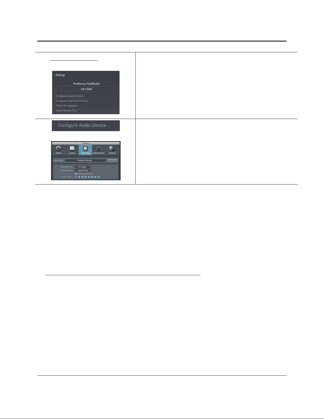
Start Page: Setup Area
Shows Active Audio Driver and Sample Rate and Provides Quick Links to
Configure Audio and MIDI
In the middle of the Start page, you will see the Setup area. Studio One Artist
automatically scans your system for all available drivers and selects a driver.
By default, it will choose a PreSonus driver if one is available.
Selecting a Different Audio Driver From the Start Page
If you do not see “PreSonus FireStudio” on the Start page when you launch
Studio One, click on the Configure Audio Devices link in the Setup area to
open the Audio Setup Options window.
In the Audio Device menu, select “PreSonus FireStudio.” Click the Apply
button and then OK.
After you have verified that the PreSonus FireStudio driver has been detected, please continue to Section
2.2.3 to set up your external MIDI devices. If you do not have any MIDI devices to connect at this time,
please skip to Section 2.2.4.
2.2.3 Configuring your MIDI devices
From the External Devices window in Studio One Artist, you can configure you r MIDI keyboard controller,
sound modules, and control surfaces. This section will take you through setting up your MIDI keyboard
controller and sound module with the FireStudio. Please consult the Reference Manual located on your
Studio One Artist installation DVD for complete setup instructions for other MIDI devices.
Setting up an external MIDI keyboard controller from the Start page.
A MIDI keyboard controller is a hardware device that is generally used for playing and controlling other
MIDI devices, virtual instruments, and software parameters. In Studio One Artist, these devices are referred
to as Keyboards, and they must be configured before they are available for use. In some cases, your MIDI
keyboard controller is also used as a tone generator. Studio One Artist views the two functions of these types
of hardware as two different devices: a MIDI keyboard controller and a sound module. The MIDI controls
(keyboard, knobs, faders, etc.) will be set up as a Keyboard. The sound module will be set up as an
Instrument.
10 | PreSonus 2008
Page 14
GETTING STARTED
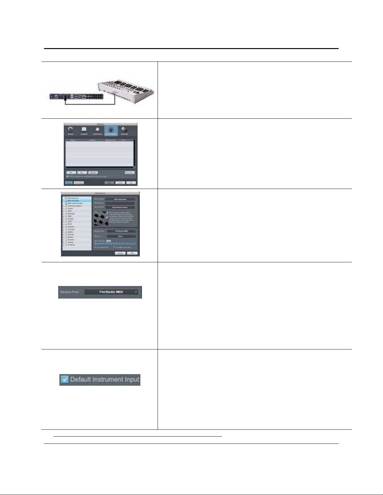
1) From the Setup area in the Start page, you can also set up your
external MIDI devices. Before we set up a new Song for recording,
let’s take a moment to configure external devices. Connect the MIDI
Out of your external MIDI controller to the MIDI In of your
FireStudio.
2) Click on the Configure External Devices link in the Setup area on the
Start page to launch the External Devices window.
Click the Add button.
3) The Add Device window will launch.
From the menu on the left, select “New Keyboard.” At this point, you
can customize the name of your keyboard by entering the
manufacturer and device names.
Specify which MIDI channels will be used to communicate with this
keyboard. For most purposes, you should select all MIDI channels. If
you are unsure of which MIDI channels to select, we suggest you select
all 16.
4) In the Receive From drop-down menu, select the MIDI interface input
from which Studio One Artist will receive MIDI data. In this case,
choose “FireStudio MIDI.”
In the Send To drop-down menu, select the MIDI interface output
from which Studio One Artist will send MIDI data to your keyboard
(also labeled “FireStudio MIDI”). If your keyboard controller does
not need to receive MIDI data from Studio One (say, for moving
motorized faders and the like), you can leave this unselected. If your
keyboard does need to receive MIDI date, you must connect a MIDI
cable from the MIDI output of the MIDI breakout cable to the MIDI
input of the keyboard.
5) If this is the only keyboard that you will use to control the virtual
instruments and your external synthesizers in Studio One Artist, you
should check the box next to Default Instrument Input. This will
automatically assign your keyboard to control all MIDI devices in
Studio One Artist.
Click OK.
If you have a sound module you’d like to connect, leave the External
Devices window open and proceed to the next part of this section. If
not, you can close this window and skip to Section 2.1.4.
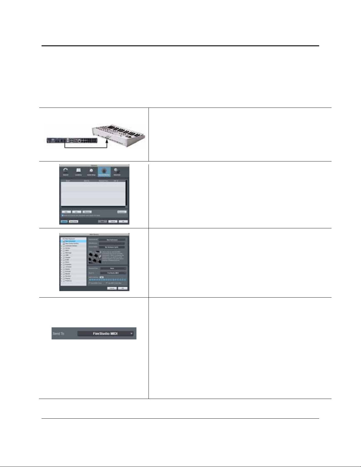
Setting up an external MIDI sound module from the Start page:
11 | PreSonus 2008
Page 15
GETTING STARTED
MIDI instrument controllers (keyboards, MIDI guitars, etc.) send musical information in the form of MIDI
data to tone modules, which respond by generating sound, as instructed. Tone modules can be standalone
sound devices or can be integrated into a controller, as with a keyboard synthesizer. Studio One Artist refers
to all tone generators as Instruments. Once you have set up your MIDI keyboard controller, take a moment to
configure your sound module.
1) Connect the MIDI In of your external sound module to the MIDI Out
of with your FireStudio.
2) In the External Devices window, click the Add button.
3) The Add Device window will launch.
From the menu on the left, select “New Instrument.” At this point,
you can customize the name of your sound module by entering the
manufacturer and device names.
Specify which MIDI channels will be used to communicate with this
keyboard. For most purposes, you should select all MIDI channels. If
you are unsure of which MIDI channels to select, we suggest you select
all 16.
4) In the Send To drop-down menu, select the MIDI-interface output
from which Studio One Artist will send MIDI data to your sound
module, in this case, choose “FireStudio MIDI.”
In the Receive From drop-down menu, select the MIDI-interface
output from which Studio One Artist will receive MIDI data from your
sound module (also labeled “FireStudio MIDI”). In most cases, your
sound module will not need to send information to Studio One, so you
can leave this unspecified.
Click OK and close the External Devices window. You are now ready
to start recording in Studio One Artist. Sections 2.2.4 through 2.2.6
will go over how to set up a Song and will discuss some general
workflow tips for navigating through the Studio One Artist
enviroment.
12 | PreSonus 2008
Page 16

GETTING STARTED
2.2.4 Configuring Audio I/O
Now that you’ve configured your MIDI devices, let’s create a new Song and set up your default Audio I/O.
1) From the Start page, select “Create a new Song.”
2) In the browser window, name your Song and choose the directory in
which you’d like it saved. You’ll notice a list of templates on the left.
The FireStudio template will create a Song with a track for each of the
available inputs. Every track is armed for recording, and no further
setup is required. Simply select this template and click “OK.”
The rest of this section will guide you through creating a Song from an
empty session.
3) To begin a new Song, select “Empty Song” from the Templates list. At
this point, you should give your Song a name and select your preferred
sample rate and bit depth. You can also determine the length of your
Song and the type of time format you would like to use (Notation Bars,
Seconds, Samples, or Frames). Click the OK button when you are
finished.
If you plan on importing loops into your Song, you may want to select
“Stretch Audio Loops to Song Tempo” so that any loop of a known
BPM (like those in the included content library) will import at the
correct tempo.
4) When the Song window launches, launch the Audio Setup window by
going to File|Options… (PC) or Studio One|Preferences (Mac), and
click on the Audio Setup button.
5) Click on the Song Setup button to open the Song Setup window, then
click on the on the Audio I/O Setup icon.
13 | PreSonus 2008
Page 17

GETTING STARTED
6) Click on the Inputs tab in the Audio I/O Setup window, and you will
see all of the available inputs on your FireStudio. At this time, you
can add the number and type of inputs you plan to use. We
recommend that you create a mono input for each of the 26 inputs on
your FireStudio. If you plan on recording in stereo, you should also
create a stereo bus and assign it to the appropriate set of inputs. You
can remove any bus by simply selecting it and clicking the remove
button. To customize the name of your buses, double-click on the
default name to open a text box. When you have finished typing, hit
Enter.
If you would like the same inputs to be available every time you
launch Studio One Artist, click the “Make Default” button.
7) Click on the Outputs tab, and you will see all of the available outputs
on your FireStudio. At this time, you can add the number of output
buses to which you would like to have access and can give them
custom names.
In the lower right corner, you will see the Audition select menu. This
allows you to choose the ouput from which you will audition audio
files prior to importing them into Studio One Artist. In general, you
will want this to be the Main Out bus.
If you would like this output configuration available every time you
launch Studio One Artist, click the Make Default button.
2.2.5 Creating a Song
Now that you’ve configured your MIDI and Audio I/O and created a new Song, let’s go through some of the
basics of Studio One Artist so you can start recording!
Creating Audio Tracks
In the upper left corner of the Arrange window, you will notice several buttons.
The middle button is the Add Tracks button. Click this button to bring up the
Add Tracks window.
In the Add Tracks window, you can select the number and type of Tracks you’d
like to create (Mono Audio, Stereo Audio, Instrument, or Automation) and
can customize the name and the color.
14 | PreSonus 2008
Page 18

GETTING STARTED
Once you have added your Tracks, you can assign the input by simply clicking
on the input to which a Track is currently assigned. This will bring up your
inputs list. You can also access the Audio I/O Setup from here.
If you would like to add a Track for each of the available inputs and have the
routing automatically assigned, simply go to Track | Add Tracks for All Inputs.
To begin recording, create an audio track, assign it to Input 1, and connect a microphone or instrument to
Channel 1 on the front panel of the FireStudio. Select the record enable ( ) and monitor ( ) on your track
in Studio One Artist. Turn up the Channel 1 gain knob on the front panel of the FireStudio while
speaking/singing into the microphone or playing your instrumen t. You should see the input meter in Studio
One Artist react to the input. Adjust the gain so the input level is near its maximum without clipping.
Connect a set of headphones to the FireStu dio headphone output. You may also wish to co nnect monitors to
the FireStudio’s Main Outs. You are now ready to record. For complete instructions, please consult the
Studio One
Creating MIDI Tracks
Reference Manual,
which is located on your Studio One Artist Installation DVD.
Click on the Add Tracks button. When the Add Tracks window launches, select
Instrument as the Track Format and click the OK button.
To assign your MIDI input, click on the MIDI Inputs list and select your
external sound module.
If you have added Virtual Inputs to your session, you will also see them as
available inputs.
If you selected your MIDI keyboard controller as the default keyboard, it will
already be selected. If not, choose your MIDI controller from Output menu
directly below.
To the left of the Add Track button, you will find the Inspector button. Click it
to display more parameters for the selected track.
At the bottom of the Inspector menu, you will see your Bank and Program
selections. From here, you can remotely change the patch on your sound
module.
15 | PreSonus 2008
Page 19

GETTING STARTED
Please Note: MIDI data does not contain audio signals. To hear your sound mo dule, you must connect the
audio output of the sound module to a FireStudio aud io input, th en conne ct the FireStudio’ s audio output s to
a sound system. (You also can listen on headphones, using the FireStudio’s headphone output.) When you are
ready to mix your Song, you must convert the recorded MIDI data to an audio waveform by recording a new
audio track.
Adding Virtual Instruments and Plug-in Effects to your Song
You can add plug-ins and Instruments to your Song by dragging-and-dropping from the browser. You can
also drag an effect or group of effects from one channel to ano ther, drag in customized effects chains, and
instantly load your favorite virtual-instrument patch without ever scrolling through a menu.
In the lower right corner of the Arrange window are three buttons. The Edit
button opens or closes the Audio editor or the MIDI piano-roll editor, depending
on what type of track is selected. The Mix button opens and closes the mixer
window.
The Browse button opens the Browser window, which displays all of the
available virtual instruments, plug-in effects, audio files, and MIDI files, as well
as the pool of audio files loaded into the current session.
To add a virtual instrument to your session, click the Browse and Instrument
buttons to open the Instrument Browser. Select the instrument or one of its
patches from the Instrument Browser and drag it into the Arrange view. Studio
One Artist will automatically create a new track and load the Instrument as the
input.
To add a plug-in effect to a track, click the Effects button and select it or one of
its presets in the Effects Browser, then drag it over the track to which you
would like to add it.
Audio and MIDI files can also be quickly located, auditioned, and imported into
your Song by dragging them from the File Browser into the Arrange view. If
you drag the file to an empty space, a new track will be created with that file
placed at the position to which you dragged it. If you drag the file to an existing
track, the file will be placed as a new part on the track.
16 | PreSonus 2008
Page 20

GETTING STARTED
2.2.6 Cue Mix and the FireStudio
In Studio One, it is possible to quickly and easily create multiple cue mixes. A cue mix is separate from the
main mix and is usually provided to musicians for monit o ri ng p ur pose s du ri n g recording.
For instance, when recording vocals, the engineer and vocalist will probab ly want to hear different mixes.
Most vocalists want to hear more of their vocals in the mix, possibly with some reverb to make it sound
natural, while the engineer might focus on how the performance balances with the rest of the mix. Together,
Studio One and a FireStudio make this simple.
1) You can create a cue mix and send it to any of 18 outputs on your
FireStudio (General Purpose, ADAT 1 out, and S/PDIF). You simply
need to create an output bus and enable Cue Mix. To begin, create a
new Song, open the Song|Song Setup. Click on the Audio I/O Setup
icon, switch to the Outputs tab, and add a new Stereo Output channel.
The Cue Mix Object
Activate Button
2) Specify that this output is a cue-mix output by clicking on the channel’s
Cue Mix checkbox. You can create a cue mix for any or all of your
audio interface’s available stereo outputs. You can customize each Cue
Mix name by double-clicking on the default name.
When you are finished, click “Apply” and then “OK” to exit.
Once you have created a Cue Mix output, you will notice a special Send object in
the channels of the Console. This Send object is called a Cue Mix object. In the
Small Console view, Cue Mix objects appear in the far left column of the
extended channel. In the Large Console view, Cue Mix objects appear below the
Send device rack on each channel.
Sends a Channel to the Cue Mix
To completely remove any channel from a cue mix, simply deactivate the Cue
Mix object for that channel.
17 | PreSonus 2008
Page 21

GETTING STARTED
Horizontal Level Fader Sets the Volume of the Channel for the Cue Mix
By default this level will be identical to the level set on the channel’s fader. Once
you move the Cue Mix level fader, the volume of that channel in the Cue Mix will
be independent of the main mix or any other Cue Mix in the session.
Horizontal Pan Fader
Sets the Pan Position of the Channel for the Cue Mix
By default, the pan position will be identical to the position set in the main mix.
Once you change the pan position in the Cue Mix, the panning for that channel
will be independent of the main mix or any other Cue Mix in the session.
Lock to Channel Button
Locks the Volume and Panning in the Cue Mix Object to the Levels Set in the
Main Mix
By default, the Lock to Channel button is enabled, and level and pan values are
locked to the Channel level and pan faders. This means that each cue mix will be
identical to the main mix in the Console. Changing the level or panning in the
main mix will change the level or panning in the cue mix. However, changing the
level or panning in the Cue Mix object will unlock both settings, allowing
independent control of level and panning for each channel in each cue mix. Thus,
the level and panning for channels in a cue mix can be completely different from
the related level and pan in the main mix. At any time, you can lock the cue-mix
level and pan back to the channel settings by clicking on the Lock to Channel
button.
Zero-Latency Switch Enables Zero-Latency Monitoring for FireStudio Inputs
Cue mixes are normally used in a recording situation in which one or more live
inputs need to be monitored. FireStudio interfaces feature internal hardware
mixers that provide zero-latency monitoring via the device window in the
Universal Control. While these mixers are easy to use, Studio One makes it even
easier by allowing you to control the mixers from within the software. Using this
feature only involves clicking just this one button.
You will notice that the FireStudio Device Window remains active while Studio One Artist is open. Because
of the powerful routing flexibility in the FireStudio Device window, FireStudio owners have the choice to use
either the FireStudio Device window or Studio One Artist’s Cue Mix feature to create their monitor mixes.
Please note: once Studio One Artist launches, DAW streams 1 through 18 will be patched to Outputs 1
through 18 on the Outputs/Router tab. If you make any changes to the FireStudio Outputs/Router tab while
Studio One Artist is open, and you want to use Cue Mix, you will need to repatch the DAW streams to their
respective outputs. For more information on Universal Control and the FireStudio device window, please
review Section 3.1. Because of FireWire streaming limitations, cue-mix zero-latency monitoring is not
available when daisy-chaining multiple FireStudio-family interfaces.
18 | PreSonus 2008
Page 22

GETTING STARTED
The Main Output as a Cue Mix
It is possible to designate the main output in Audio I/O Setup as a cue mix. This is helpful if you often record
yourself require quick access to zero-latency monitoring for live inputs. When the main output is designated
as a cue mix, a Zero Latency button will appear on any audio channel with an assigned audio input in the
Console, below the Mute, Solo, Record, and Monitor buttons.
With the Zero Latency button and Monitor Enable both engaged, you will hear the live zero-latency input
straight from your FireStudio (as opposed to through software). As such, you will no longer hear the effects
of any inserts on the channel. However, you will still hear the result of any sends on the channel, as Bus and
FX Channels will still output normally.
19 | PreSonus 2008
Page 23

GETTING STARTED
2.3 SAMPLE HOOK UP DIAGRAMS
With the FireStudio, you can simultaneou sly record and play back up to 26 channels. Since it is loaded with
eight preamplifiers, you can plug in eight microphones to th e FireStudio. Using the ADAT optical and S/PDIF
inputs, you can connect external A/D devices like the DigiMax FS. This makes recording extremely easy. All you
need are microphones, cables, and monitor speakers.
2.3.1 Mobile Recording with the FireStudio and Two DigiMax FS
20 | PreSonus 2008
Page 24

GETTING STARTED
2.3.2 Full Band Setup Using the MSR in Track Mode
Please note: This setup can be used with or without an MSR connected. This example implies that seven monitor mixes have
been created in the FireStudio Device window and routed to the 8 General Purpose outputs of the FireStudio and 4 of the
DAC outputs on the DigiMax FS in stereo pairs. The seventh mix is assigned to an unused output and copied to the Main
Outputs for control room monitoring (see below). By connecting an ADAT cable to both the input and the output of the
DigiMax FS, it can be used to expand the outputs of the FireStudio as well as to add more analog inputs.
21 | PreSonus 2008
Page 25

CONTROLS AND CONNECTIONS
3.1 UNIVERSAL CONTROL AND THE FIRESTUDIO
Like all members of the FireStudio family of interfaces, the FireStudio is compatible with Universal Control.
Universal Control is a powerful, flexible, and easy to use control-panel application that enables you to create 9
mixes from your input and output signals and lets you patch any input or playback stream to the first 18 of your
FireStudio outputs. This application also allows you to da isy-chain FireStudio-fa mily interfaces. The FireStudio
can be connected to up to 3 other FireStudio-family devices, creating a system with a maximum of 52 inputs and
outputs.
Universal Control consists of the Launch window and the Device windo w. In the Launch window, you can set
basic parameters such as sample rate, clock source, and buffer size. The Device window of the FireStudio is the
FireStudio Mixer. The Mixer section of the Universal Control Panel was designed to look and feel like a
hardware mixer, so most of the features may already be familiar to you. From this mixer, you can create a zerolatency mix for each output and can route playback streams from your host application.
3.1.1 Universal Control Application Icon
If you are using Microsoft Windows, once you have successfully installed your
FireStudio, the Universal Control will be available from the Notification Area of your
taskbar (typically at the bottom right corner of your screen, near the clock).
The Universal Control icon is red when your FireStudio is disconnected or not installed and blue when the
FireStudio is connected and properly installed.
Open the Universal Control by double-clicking the b lue Universal Control icon or by right-clicking the icon
and selecting “Open PreSonus Universal Contr ol. ”
Right-click the Universal Control icon and select “Quit” to exit the Universal Control application and remove
it from your taskbar. The Universal Control application can also be accessed from the PreSonus folder in the
Start Menu.
Mac OS X users will find the Universal Control application in the Applications folder. We
recommend that you move it to your Dock for easy access.
22 | PreSonus 2008
Page 26

CONTROLS AND CONNECTIONS
3.1.2 Launch Window
From the Launch Window, you can set all the basic controls for your FireStudio.
Sample Rate Selector
Changes FireStudio Sample Rate
You can set the sample rate to 44.1, 48, 88.2, or 96 kHz. A higher sample rate
will increase the fidelity of the recording but will increase the file size and the
amount of system resources necessary to process the audio.
Buffer Size Selector Changes the FireStudio Buffer Size (Windows PCs Only)
You can set the buffer size from 64 to 4,096 samples. The buffer size determines
the latency, which is the roundtrip time it takes audio data to be converted from
analog to digital and back to analog. As a general rule, the higher the buffer size,
the better the system performance, but the less playable virtual instruments
become. In general, 512 samples (11 to 12 milliseconds) will provide you with a
buffer that is large enough for optimum system performance, but small enough to
be unobtrusive. You should set your buffer size and sample rate prior to
launching your host applciation.
On Macintosh, the buffer size is set from inside your host application.
Operation Mode Changes How the FireStudio Driver’s Buffer Size is Set
Changes the Clock Source for the FireStudio
Clocksource
The clock source setting will determine the port from which the FireStudio is
receiving word-clock information. This keeps the FireStudio in sync with other
digital devices. You can choose between Internal, BNC, S/PDIF, ADAT 1, or
ADAT 2.
In general, you will want the FireStudio to be your master clock, in which case
you should set the clock to "FireStudio - Master." This setting also means that
your FireStudio is generating word clock and sending this information out of its
digital outputs.
If you want the FireStudio to receive sync from an external device, choose the
digital input to which the external device is connected (i.e. S/PDIF, ADAT, or
BNC Wordclock). The FireStudio's sync light will flash from blue to red. When
the FireStudio is in sync, the light will be blue.
Please note: When slaved to an external clock, the FireStudio will not
automatically change its sample rate to match the external clock. As a result, it
may fail to sync to the clock source. If your FireStudio is not syncing to an
external source, make sure that both your master device and the FireStudio are
set to the same sample rate.
Normal Mode. Input and Output buffers are both identical to the Buffer
Size setting.
Safe Modes 1-3. Increases the Output buffer size for added stability.
23 | PreSonus 2008
Page 27

CONTROLS AND CONNECTIONS
Device Window Button Opens the Device Window
Click on this button to open the FireStudio Device window.
To give your FireStudio a custom name, double-click on the default label
(FireStudio) to open a text field. When you have finished entering your custom
name, hit the Enter key.
File Menu Opens and Closes Launch and Device Windows
From the File menu of the Launch Window, you can open and close both
windows, as well as quit the Universal Control application.
Close Window. Closes just the Launch window.
Show All Devices. Opens the Device window for all of the connected
FireStudio-family interfaces.
Close All Devices. Closes the Device window for all of the connected
FireStudio-family interfaces.
Quit. Quits the Universal Control application.
Settings: Check Firmware Automatically Scans Your FireStudio and Updates the Firmware
A firmware updater is built into the Universal Control application. Periodically,
a driver update will require that the firmware on your FireStudio be updated.
Whenever you install an update for the Universal Control or add a new
FireStudio-family product to your system, you should use this feature to ensure
that the firmware is up to date. If the firmware needs to be updated, the update
application will launch automatically.
Settings: Run at Startup Launches the Universal Control Application Automatically on Startup (Windows
PCs Only)
When this is enabled, the Universal Control application will automatically launch
each time you boot your Windows PC.
Settings: Meter Style Provides options for Metering in the Device Window.
From the Launch Window, you can determine how your Inputs and DAW streams
are metered in the Device Window.
Post-Fader. Displays the metering for any signal after it has been
boosted or attenuated by the channel fader. By default, all metering is
Pre-Fader position.
Peak Hold. When this is enabled, the clip indicator on any given
channel will remain illuminated until manually cleared, even if the
signal is no longer clipping. This is enabled by default.
24 | PreSonus 2008
Page 28

CONTROLS AND CONNECTIONS
Settings: Meter Decay Sets the Response Time for the Meters in the Device Window
The Universal Control gives you the option to set the response time for the meters
in the Device Window. By default, this is set to Normal. Enable Slow Meter
Decay for more accurately meter the peaks and falls of the signal. Enable Fast
Metering to monitor your signal in realtime.
Settings: Always On Top Allows the Launch Window to Stay in View When Other Applications Are in Use
When this is enabled, the Launch window will remain in the foreground when
other applications are active, rather than being in the background behind the
current application’s window.
3.1.3 WDM Settings (PC only)
Like the rest of the FireStudio family of interfaces, the FireStudio features advanced WDM features that
enhance its use as an audio interface. In the Settings menu of the Launch window, you will find the WDM
Setup option. From here you can configure your WDM input and out pu t stre ams.
1) In the Lancher window, go to Settings|WDM Setup.
2) The WDM Channel Mapper window will open. By default, WDM
Outputs 1 and 2 are routed to FireStudio DAW Streams 1 and 2. To
change the default routing, simply select WDM Output 1 and 2 and
drag them to your preferred output pair.
25 | PreSonus 2008
Page 29

CONTROLS AND CONNECTIONS
3.1.4 The Device Window: Overview
The FireStudio is a revolution in PreSonus interface design because of the flexible routing and mixing
capabilities of the FireStudio Device window in the Universal Control application. In the Device window, you
can:
Create up to 9 different stereo mixes of inputs and playback streams for flexible zero-latency monitor
mixing (i.e. not everyone in the band has to listen to the same thing)
Create sends and returns for any input to incorporate external processors with zero latency.
Provide every input with its own hardware output to incorporate a large format console or another
recording device
Send mixes out of analog and digital outputs simultaneously
Route playback streams to separate physical out puts for live mixing
The FireStudio Device window consists of three sections: Mixer, Outputs/Router Matrix, and Hardware
Settings. We'll go through each of these sections individually.
3.1.5 The Device Window: Hardware Settings Tab
In the Device window, you can set all the basic controls for your FireStudio, including the features that are
enabled when an MSR is connected.
FireStudio Settings: Terminate BNC Terminates BNC
FireStudio Settings: Expanded Mix
Mode
FireStudio Settings: Quick Route Allows You to Route a Monitor Mix to the Desired Output From the Mixer Tab
FireStudio Settings: Reset Names to
Defaults
Check this box to terminate the BNC word-clock input. This may be necessary to
achieve stable sync depending on the external device to which you are syncing. If
this device is not self terminating, use this box.
Allows Access to All 26 Inputs (44.1 and 48 kHz Only)
Enabling Expanded Mix Mode replaces DAW playback streams 9-16 with ADAT
2 inputs 17-24. This allows you to create zero-latency monitor mixes with all 26
inputs and 8 individual playback streams from your DAW application.
Digital Mode.
When Digital Mode is selected, you will have the option to
route the selected monitor mix to ADAT outputs 9/10, 11/12, 13/14, or
15/16 or to S/PDIF outputs 17/18.
Monitor Mode.
When Monitor Mode is selected, you can route the
selected Mix to the main outputs or to any of the headphone outs. You
also can have the mixes automatically route to one of these same outputs
as you tab through your nine monitor mixes.
The Quick Route features will be discussed in greater detail in section 3.1.7.
Resets User-Defined Names
Clicking this button will reset all user-defined names for Mixes and Inputs in the
FireStudio Device window to factory defaults.
26 | PreSonus 2008
Page 30

CONTROLS AND CONNECTIONS
MSR Settings: Copy 1/2 to Mains in
Surround Mode
Allows You to Use Mute or Enable Your Main Monitors in Surround Mode
Enabling this feature allows you to use the monitors connected to the Main L/R
outputs as your front left/right pair in Surround mode, without having to recable
anything. If you use a different set of monitors for stereo mixing, disabling this
MSR Settings: Talkback to Digital
Outs
feature will automatically mute these monitors when you switch into Surround
mode.
Sends the Talkback Mic to All Available Outputs on the FireStudio
When this feature is enabled, the talkback mic on the MSR will be routed to the
S/PDIF and ADAT outputs (to ADAT 1 output only when operating at 44.1 kHz
and 48 kHz). If you are using your digital outputs for something other than
Version Information Displays Information About Your FireStudio
additional monitoring, you should disable this feature.
This section displays the current firmware and FPGA version of your FireStudio,
as well as the version number of the Universal Control application.
3.1.6 The Device Window: Outputs / Router Matrix
True to its name, the Outputs/Router Matrix is the section of the FireStudio Device window where you have
full control of the physical outputs of your FireStudio. The Matrix Router allows you to create custom
routings of inputs and playback streams to any out p ut. W ith the Ou tp u ts / R oute r Ma trix you can:
• Route a monitor mix to a stereo output
• Assign every input and playback stream to its own output
• Do quick AD/DA conversion on the fly
The Matrix Router can do it all quickly and easily. This is the virtual patch bay for your FireStudio recording
environment.
A quick note on playback streams: Wherever you see "DAW" in the FireStudio Device window, this is a
playback stream from your host application (or DAW). Traditionally, if you want to route a track in your
DAW to a physical output on your interface, you assign this output in your host application. Because the
FireStudio Device window provides much more flexible routing, you can now route this same track to one
output or to every output, by itself or as part of a mix.
For example, if you choose "FireStudio Out 4" for a track or virtual instrument in your DAW, FireStudio Out
4 will indicate a virtual output rather than a physical output. This track is now "DAW 4" in th e FireStudio
Device window. The track can still be routed to the FireStudio's physical output 4, but you can also route it to
output 2 or 16 and include it in the monitor mix assigned to outputs 7 and 8. We'll get to that a little later.
Please note: ADAT 2 outputs (FireStudio outputs 17-24) can be directly accessed from your DAW
application; no additional routi ng is av ai la bl e in the FireStu dio Devi ce wind ow.
27 | PreSonus 2008
Page 31

CONTROLS AND CONNECTIONS
/
Inputs and Playback-Stream Routi ng
Along the left side of the router matrix, there are two tabs: “Inputs” and “Playback.” When the Inputs tab is
selected, the matrix will show any inputs that have been routed. When the Playback tab is selected, you can
view your playback streams or virtual DAW outputs in the router matrix. The Router Matrix patches the
selected input or playback stream directly to the specified out put.
Inputs
Input Source
Source 1 Tab
OR
Selecting this tab will allow your to view your analog, ADAT 1, and
S/PDIF inputs in the router matrix.
If you are in Expanded Mix Mode, this tab will be named “Source 1.”
Playback Source Viewer
When the Inputs tab is selected, you will see a list of your physical inputs
(Mic/Inst 1, Mic/Inst 2, etc.). Clicking on any box in the row next to each
input will assign it to the output at the bottom of that column.
If you assign a playback stream to an output on the Playback or Source 2
tab, this routing will be shown in the row directly above that output.
28 | PreSonus 2008
Page 32

CONTROLS AND CONNECTIONS
Playback/Source 2 Tab
OR
Playback Source
Selecting this tab will allow you to view your DAW playback streams in the
router matrix.
If you are in Expanded Mix Mode, this tab will be named “Source 2”. You
will be able to view DAW playback streams 1-10 and the ADAT 2 inputs.
When the Playback tab is selected, you will see a list of your virtual DAW
outputs (DAW 1, DAW 2, etc.). Clicking on any box in the row next to each
playback channel will assign it to the output at the bottom of the column.
Remember, these DAW outputs are streaming directly from your host
application. If you wish to assign a virtual instrument or a previously
recorded track to one of these playback streams, you must first route the
output of that track in your host application. (e.g., “FireStudio DAW
Channels 1-16 and 25-26” in your DAW’s output selection translates to
“DAW 1-16 and 17-18” in the FireStudio Device window. Remember
FireStudio DAW Channels 17-24 are not accessible through the FireStudio
Device window. Rather, they are directly routed to the ADAT 2 output.)
If you are in Expanded Mix mode, you will also be able to route your ADAT
2 inputs on this tab.
OR
Input Source Viewer
If you assign an input to an output on the Input or Source 1 tab, this routing
will be shown in the row directly above that output.
29 | PreSonus 2008
Page 33

CONTROLS AND CONNECTIONS
Mix Routing to Outputs
In addition to being able to patch any input to any output, you can also assign up to nine different stereo
mixes to any pair of outputs and can assign yo ur main outputs and headphone outputs to mimic a physical
output.
Mix Source Button
Clicking on the Mix Source button above the desired pair of outputs allows
you to assign any one of the nine stereo monitor mixes that the FireStudio
Device window allows you to create.
The Mix Source buttons are visible regardless of which router tab is currently
active. When you have assigned a monitor mix to a pair of outputs, the
button will show the name of that mix.
Router Presets
Main Assign Section
Main Assign LEDs
The FireStudio Device window allows you to save six router presets. To save
a routing scheme, simply click “Save” and then one of the preset numbers.
To recall a preset, simply click on the number.
The Default button resets the Router matrix so that each playback stream is
routed to its own output.
The main L/R outputs and each of the headphone outputs can be assigned to
mimic any physical output.
To assign one of these monitor outputs, click on its button. It will turn blue.
Mouse over to the output you wish to mimic, and you will see a volume
potetiometer appear over the output. Left-click this image to audition the
output. Double left-click it to assign. Click on the monitor output button
again to lock your selection.
Please note: The MSR must be connected for Phones 2 and 3 to be
accessible.
Once you have assigned the main or headphone outputs to a particular output
pair, an LED will light up above those faders, indicating an assignment has
been locked.
MO: Main Output
P1: Phones 1
P2: Phones 2
P3: Phones 3
30 | PreSonus 2008
Page 34

CONTROLS AND CONNECTIONS
Output Faders
At the bottom of the Outputs/Router tab, you will see all of your physical outputs enumerated (Analog 1
through S/PDIF R). Each output is visually represented as a fader.
Channel Fader
Real-time Decibel Readout
Fader Attenuation
Clip Indicator
Stereo Link
Mute
The fader controls the volume of the signal on any given output. A meter to
the right of the fader indicates the level in real time.
Above the meter on each channel strip, you will see a number. This is the
decibel (dB) level of the signal being routed to that ouput.
Below the meter you can see the fader attenuation (-96 to 0 dB). Unity is
indicated by O dB and is achieved by raising the fader all the way up. When
the fader is at its lowest position, the value will be -96 dB.
Each meter is equipped with a clip indicator to alert you should your levels
get too hot. A red “C” will illuminate when the track has clipped and will
remain illuminated until it has been reset. To reset the meter, simply click on
the “C”.
The Link button joins outputs into stereo pairs. To enable this, simply click
on the word “LINK.” The letters will turn blue. To separate the channels,
click the word “LINK” again. When channels are linked, the volume of both
will be controlled with either fader.
The Mute button cuts all signal coming from the specified output. If the
channels are linked, muting either of the channels will mute both.
31 | PreSonus 2008
Page 35

CONTROLS AND CONNECTIONS
3.1.7 The Device Window: Mixer tab
The FireStudio Device window allows you to create 9 stereo monitor mixes. The mixes can be renamed and
saved. You can also rename you inputs and playback streams.
It is important to mention that these mixes have no effect on what is being recorded in your host application.
This has obvious advantages. However, it is vital to remember that lowering the fader in the FireStudio
Device window on a channel strip that is clipping will not lower the signal that may also be clipping in your
host application. You must set the level for the recording using the physical trim pots on the face of the
FireStudio. If your signal is too hot in your DAW, it is these pots that will need to be lowered.
The Mixer is made up of 18 inputs and 18 playback streams (Standard Mode) or 26 inputs and 10 playback
streams (Expanded Mix Mode), each with its own channel strip. Just like in the Outputs / Router Matrix, you
have control both over your physical inputs and y o u playback streams from your host applicati on.
Across the top row, you will see your Analog, S/PDIF, and ADAT 1 inputs. Across the bottom row, you will
see your playback streams. In Expanded Mix Mode, you will also see you r ADAT 2 inputs. These playback
streams come directly from your host application. Each track or Virtual instrument in your session can be
assigned from within your host application to a FireStudio output. This output will be reflected as a
corresponding DAW channel in the FireStudio Device window.
Channel Fader Controls
Each input and playback stream is equipped with its own fader strip. This strip has all the same features as a
classic physical console.
Channel Fader
The fader controls the volume of the signal on any given output.
The signal is metered in realtime directly to the right of the fader.
Pan Slider
Above each fader you will see a box with a vertical line. This is
your pan control. As you move the pan to the left or right of
center, the “C” below it will change to reflect that channel’s
Real-Tme Decibel Readout
current pan position.
Above the meter on each channel strip, you will see a number.
This is the decibel (dB) level of the signal being routed to that
ouput.
32 | PreSonus 2008
Page 36

CONTROLS AND CONNECTIONS
Fader Attenuation
Below the meter you can see the fader attenuation (-96 to 0 dB).
Unity is indicated by O dB and is achieved by raising the fader all
the way up. When the fader is at its lowest position, the value will
be -96 dB.
Below each fader is the Mute button for that channel. Engaging
Mute Button
the Mute button will mute that input or playback stream on the
Solo Button
Clip Indicator
current mix only.
Below each meter is the Solo button for that channel. Engaging
the Solo button will mute all other inputs and playback streams
that are not also soloed in the current mix.
Each meter is equipped with a clip signal. A red “C” will
illuminate when the track has clipped. To reset the meter, simply
click on the “C”.
Please note: The metering in the FireStudio Device window is
completely independent of your host application. If an input
signal is clipping while being recorded, lowering the volume in the
FireStudio Device window will not lower the volume in your DAW
application. Be sure to monitor your inputs in you DAW as well
as the monitor mixes you are creating in the FireStudio Device
window. If a signal is clipping in your DAW, you must adjust the
Link Button
physical trim pot on the face of the FireStudio.
The Link button joins outputs into stereo pairs. To enable this,
simply click on the word “LINK.” The letters will turn blue. To
separate the channels, click the word “LINK” again. When
channels are linked, the volume of both will be controlled with
either fader.
Master Fader
Each mix has its own master fader control independent o f the Out puts / Rou ter Matrix.
Master Fader
The Master Fader for each mix has all the same features as the
output faders on the Outputs/Router Matrix tab. For a complete
detailing of each feature, please review the Output Fader portion
of Section 3.1.5.
33 | PreSonus 2008
Page 37

CONTROLS AND CONNECTIONS
Quick Route section
During a recording session, time is of the essence. The Quick Route section allows you to assign the current
monitor mix to the any physical output without bringing up the Outputs/Router matrix. As explained in
section 3.1.4, there are two modes for the Quick Route option: Digital and Monitors. When Digital is
enabled, all 18 of the outputs available in the FireStudio Device window are visible.
See below:
Quick Route: Digital
Selecting any or all of the output buttons will route the current
mix to the enabled output. The buttons will turn blue when
enabled.
When “Monitors” is selected on the Hardware Settings tab, the Quick Route section allo ws you to assign the
current mix to any analog output and to automatically route the current mix to either the Main outs or to one
of the headphone outputs. This enables you to quickly preview mixes as you scroll through the nine monitor
mixes. Please note: the digital outputs are still accessible and the mixes can still be routed to them on the
Outputs/Router Matrix.
Quick Route: Monitors
Selecting any of the output buttons will route the current mix to
the enabled output.
Please note: The MSR must be connected for Phones 2 and 3 to
be accessible.
Quick Route: Auto
MO: Main Output
P1: Phones 1
P2: Phones 2
P3: Phones 3
The Auto feature will automatically route whatever mix is
currently selected to a chosen monitor output. This allows you to
switch between mixes without having to select a new monitor
routing each time.
34 | PreSonus 2008
Page 38

CONTROLS AND CONNECTIONS
3.1.8 The Device Window: Naming inputs and mixes
You can customize the names of inputs, playback streams, and mixes on the FireStudio Device window. Once
these names have been changed on the Mixer tab, the changes will be reflected on the Output/Router Matrix
tab, making it easy to know at a glance what is connected to each input and for whom each monitor mix was
created.
To name your mixes, simply right-click or CTRL-click on the mix name you wish to change. A text box will
appear where you can type in the new name.
In this way, you can name all nine monitor mixes.
Once you have named all your mixes, you will see these same custom names on th e Output/Router Matrix
when you click on a Mix Source button.
You can also name your inputs and playback streams. Each mix will reflect the changes you make to the
scribble strip on each channel and, again, these changes will also be viewable on the Output/Router Matrix.
To change the inputs, simply double-left-click on the input name and type the name you wish to use instead.
Renaming your inputs and mixes allows you to fully customize your FireStudio Device window for faster
mixing and routing and lets you get down to the business of ma ki ng a su ccessf ul recordi n g.
35 | PreSonus 2008
Page 39

CONTROLS AND CONNECTIONS
3.2 FRONT PANEL LAYOUT
Microphone Preamplifier.
microphone preamplifiers for use with all types of microphones (includ ing dynamics, condensers, and
ribbons). As well as instruments and line-level signals. The PreSonus preamplifier design employs a
Class A input gain stage. This arrangement results in ultra-low noise and wide gain control, allowing
you to boost desirable signal without increasi n g unw a nted background noise.
o
48-Volt Ph antom Pow er.
button switches on the front panel. The top button activates phantom power for channels 1-4.
The bottom button activates phantom power for channels 5-8.
XLR-connect or wi ring fo r ph ant om pow er :
+14 dBu Headroom.
o
feature gives you wide dynamic range and excellent transient-response characteristics.
o
Combo Connectors.
connector lets you use either female ¼” phone or XLR connectors in the same jack. The ¼”
inputs on channels 3-8 are line-level inputs. When these inputs are engaged, the microphonepreamp circuit is bypassed.
Your FireStudio is equipped with eight custom designed PreSonus XMAX
The FireStudio has 48V phantom power available in two groups via
Pin 1 = Ground
Pin 2 = +48V
Pin 3 = +48V
The FireStudio microphone preamplifier has +14 dBu headroom. This
Each channel of the FireStudio has a Combo mic/line connector. This
Instrument Inputs (Channels 1 and 2).
instrument (guitar, bass, etc.). When an instrument is plugged into the ¼” input, a high impedance
input buffer is switched into the preamp circuit and the FireStudio becomes an active instrument
preamplifier.
NOTE: Active instruments are those that have an
instruments should be plugged into a line input rather than into an instrument input. Plugging a linelevel source into the instrument inputs on the front of the FireStudio not only risks damage to these
inputs but also results in a very loud and often distorted audio signal. Therefore, don’t plug a line-level
source into the combo jacks of channels 1 or 2.
These two channels also feature a send and return on the back panel of the FireStudio. The return
inputs can be used as line-level inputs for these two channels if instrument preamps are not needed.
The ¼” TS connector on Channels 1 and 2 are for use with an
internal preamp
36 | PreSonus 2008
or a
line-level output
. Active
Page 40

CONTROLS AND CONNECTIONS
Input Gain/Trim Control.
XLR Microphone Inputs:
o
TS ¼” Instrument/Hi-Z Inputs:
o
TRS ¼” Line Inputs:
o
Main.
Phones.
¼” Headphone Jack.
Red-Blue Power/Sync Light.
The Main knob controls the output level for the main outputs on the back of the FireStudio and
has a range of -80 db to +10 dB.
The Phones knob controls the output level of the headphone output on the front of the unit.
Notice the volume indicator goes to 11; use this setting with extreme caution.
receiving word clock correctly. Word clock is a signal with which digital devices sync frame rates.
Proper word-clock sync prevents digital devices from having pops, clicks, or distortion in the audio
signal due to mismatched digital-audio tr ansmi ssion.
o
Blue.
FireStudio is correctly synced via FireWire, external ADAT, S/PDIF, or BNC word
clock.
o
Flashing Red and Blue
Power Button
again to power down your FireStudio.
. Push this button to turn your FireStudio on. The button will illuminate blue. Push it
These knobs provide the following gain structure:
54 dB of variable gain (-4 dB to +50 dB)
54 dB of variable gain (-4 dB to +50 dB)
32 dB of variable gain (-16 dB to +16 dB trim adjustment)
This is where you connect your headphones to the FireStudio.
This light is a clock source (sync) indicator. It lets you know if your unit is
. Sync invalid or not present.
37 | PreSonus 2008
Page 41

CONTROLS AND CONNECTIONS
3.3 BACK PANEL LAYOUT
Power Adapter Input. This is where you plug in the proprietary power supply. The FireStudio features a
locking connector to ensure solid power connectivity.
FireWire Ports.
(and only one) should be used to connect your FireStudio to a FireWire port on your computer. If your
computer has a four-pin connector (commonly found on laptops), you will need a four-to-six-pin
connector to connect your FireStudio to your computer.
Use the second FireWire port to connect additional FireWire devices to you comp uter (such as external
hard drives).
There are two standard six-pin FireWire ports on the back of the FireStudio. Either
MIDI Input and Output.
be used for many things other than instruments and sequencing. The MIDI inputs and outputs on the
back of the FireStudio allow connection to a variety of MIDI-equipped hardware, such as keyboard
controllers, and can be used to send and receive MIDI Machine Control and MIDI Time Code.
MIDI stands for “Musical Instrument Digital Interface.” However, MIDI can
Note: MIDI does not carry audio signals but is frequently used to trigger or control an audio source,
such as a virtual instrument or hardware synthesizer. You should ensure that MIDI data is correctly
sent and received by the appropriate hardware or software. You may also need to route hardware sound
sources’ audio to the FireStudio. Please consult the User’s Manual of your MIDI devices for help with
MIDI setup and usage.
BNC Input and Output.
other digital audio devices.
These allow the FireStudio to receive and transmit word clock to and from
You will need to select “wordclock” as the Clock Sour ce and set the sample rate to correspond to the
external device in the Universal Control Launch window when using the BNC input.
clock cable is required to achieve proper sync.
38 | PreSonus 2008
A 75Ω BNC word-
Page 42

CONTROLS AND CONNECTIONS
ADAT–S/MUX Input and Output These are the ADAT–S/MUX connections for your external digital
devices. When recording or playing back at 44.1 kHz or 48 kHz, each ADAT I/O will pro vide 8 of the
16 channels consecutively from left to right. When recording or playing back at 88.2 kHz or 96 kHz,
each connection will provide 4 of the 8 channels.
o
ADAT 1
ADAT 2
o
The ADAT–S/MUX I/O also allows the FireStudio to send and receive word clock to external digital
devices.
You should select “ADAT 1” or “ADAT 2” as the Clock Source and set the sample rate to correspond
the external device in the Universal Control Launch window when using one of these inputs for external
sync.
S/PDIF In and Out Jacks.
up to 24 bit, 96 kHz. The S/PDIF I/O also allows the FireStudio to send and receive word clock to
external digital devices.
You should select “S/PDF” as the Clock Source and set the sample rate to correspond to the external
device in the Universal Control Launch window when using the S/PDIF input for external sync.
: Channels 1-8 (44.1/48 kHz) or 1-4 (88.2/96 kHz)
: Channels 9-16 (44.1/48 kHz) or 5-8 (88.2/96 kHz)
The S/PDIF standard allows two channels of audio to be transmitted at rates
Aux Input.
This unbalanced stereo RCA input is for use with any device with an analog RCA output.
This input is only available when the MSR is connected. It allows quick comparison of your internal mix
with other playback material (e.g., comparing your mix to a CD). To listen to this input, select the Aux
button on your MSR.
Remote Control Input. This is the connection for the optional MSR: Monitor Station Remote. The MSR
connects to the FireStudio with a standard CAT5 (Ethernet) cable.
39 | PreSonus 2008
Page 43

CONTROLS AND CONNECTIONS
Main Output. This stereo TRS output derives its source signal from the FireStudio Device window, as
described in Section 3.1.6. This output level is attenuated by the Main Level control on the front panel
of the FireStudio.
General Purpose Line Outputs (TRS Balanced).
line outputs can be accessed in the FireStudio Device window and can be used for separate mixes,
additional speakers, external effects processors, etc.
These are general-purpose line-level outputs. All eight
Both the Main Output and the General Purpose outputs have additional functionality when an MSR is
connected to the FireStudio.
When using the MSR for monitor switching the outputs are route d as follow s:
o
Main Output Left/Right.
General Purpose Outputs 7/8.
o
General Purpose Outputs 5/6.
o
When using the MSR for 5.1 surround-sound monitoring, the General Purpose outputs are assigned as
follows:
General Purpose Output 1:
o
General Purpose Output 2:
o
General Purpose Output 3:
o
General Purpose Output 4:
o
General Purpose Output 5:
o
General Purpose Output 6:
o
Monitor set A
Monitor set B
Monitor set C
Front Left
Front Right
Rear Left
Rear Right
Front Center
Sub
As mentioned in section 3.1.5, the Main Outputs can be used as the Front Left and Front Right
monitors when mixing in surround, or they can be assigned separately from the surround monitors.
40 | PreSonus 2008
Page 44

CONTROLS AND CONNECTIONS
Return 1 and 2 (Line Inputs).
is identical to the ¼” inputs for channels 3-8 and are typically used for signals not requiring
preamplification (CD/MP3 players, effects processors, etc.). These inputs are normalled to the channel
1 and 2 preamp outputs, so they take precedence over the corresponding Mic/Instrument input on the
front of the FireStudio. (This means that if a cable is plu gged into the channel 1 return input on the
rear of the FireStudio, the channel 1 Mic/Instrument input will be inactive, and it will become active
again when the cable is removed from return input 1.)
Send 1 and 2 (Preamp 1 and 2 Outputs).
channels 1 and 2. They are half-normalled to the preamp inputs 1 and 2, so plugging a cable into either
of the preamp outputs does not interrupt the signal flow from the preamps to t he AD conve r ter.
These are the line-level inputs for channels 1 and 2. Their gain structure
These ¼” jacks are balanced outputs of the preamps on
Note: The Send outputs are typically used for patching in external signal processors (such as
compressors, limiters, EQs, and de-essers) to process the audio signals on channels 1 or 2. These
outputs are not connected to the digital-to-analog converters and so are only capable of routing the
input signals from channels 1 and 2. If you need to route recorded audio or input from channels 3
through 8, you will need to use the FireStudio Device window to route the input to one or more of the
General Purpose Outputs.
4.1 USING MULTIPLE FIRESTUDIO-FAMILY INTERFACES
Universal Control allows you to connect up to two FireStudios or to connect any member of the FireStudio
family of interfaces with any other. Once you have installed the Universal Control and FireStudio-family dr iver
on your computer, no further installation is required for any FireStudio prod uct to connect to your sy stem.
PreSonus supports the connection of up to four devices or a limit of 52 inputs and outputs (whichever comes
first) to any one system at a time. However, the ability to use more than two units simultaneously depends on
your computer’s specifications and optimization. If you plan to use three or more units at the same time,
installation of a dedicated FireWire bus with a tested and approved FireWire chipset and at least 2 GB of RAM
is highly recommended. A list of approved chipsets can be found in Section 5.1 of this manual. Updated lists are
available at www.presonus.com
Below is a diagram showing the possible device combinations that you can use with your FireStudio Mobile and
the resulting input and output count.
.
41 | PreSonus 2008
Page 45

TECHNICAL INF ORMATIO N
42 | PreSonus 2008
Page 46

TECHNICAL INF ORMATIO N
How to Cascade Multiple FireStudio Interfaces:
The first time you add any FireStudio-family interface to your system, please follow these guidelines:
1. Go to www.presonus.com and check for the latest version of the Universal Control application.
2. Connect and sync each of your FireStudio-family interfaces to your computer separately before
cascading them.
3. Once a unit is individually connected, launch the Universal Control application. In the Launch window,
go to Settings | Check Firmware and verify that each unit has the latest firmware.
4. When the last unit has been updated, connect a second unit to the auxiliary FireWire port on the back
of the first unit. Allow the second unit to sync to your computer.
5. Connect additional units to your computer in this manner, one at a time, allowing each to sync before
connecting another FireStudio-family interface.
6. Once all your units are connected and synced, launch the Universal Control application. The individual
Device Window Buttons will be shown in the Launch window in the order of their internal ID nu mber.
The unit with the lowest ID number will always be at the top of the list. This unit will also be the first
set of inputs and outputs your DAW application sees. The unit with the next highest ID number will be
the next set, and so on. Because of this, it is important to ca scade your FireStudio interfaces in the
proper order from your computer so that you know which input belongs to which unit.
Please note: The order of the inputs and outputs in your FireStu dio ch ai n can n ot be altered.
If you are using two or more of the same model (e.g., two FireStudios), you will need to look at the
serial number on the bottom of each unit (the internal ID number is the same as the unit’s serial
number) and connect them to your computer from lowest to highest. You may also wish to give each
unit a custom name. To do so, simply double-click on the name badg e on each unit’s Device Window
button to open a test box. Once you have typed the custom name, hit the Enter key.
If you are using two or more different FireStudio family interfaces, make sure to reconnect them in the
order that their individual Device Window Buttons appear in the Launch window. Connecting your units
in this order will produce the best performance and will put your inputs and outputs in the correct order.
It is important to mention that the inputs and outputs on each unit in the chain are independent from one
another. This means that you cannot monitor the inputs from th e first unit in the chain through the outputs on
the second unit in the chain unless you create a mix from within your DAW application. To easily maintain zerolatency mixing between the daisy-chained units, dedicate a set of outputs and a set of inputs from each device in
the chain to send a receive a mix in the Universal Control application.
43 | PreSonus 2008
Page 47

TECHNICAL INF ORMATIO N
5.1 TROUBLESHOOTING
Many technical issues can arise when converting a standa rd computer into a digital audio workstation (DAW).
PreSonus can only provide support for issues that directly relate to the FireStudio interface and Studio One
Artist software. It may be necessary to contact the manufacturer of the computer, operating system, and thirdparty DAW software to obtain additional technical support. PreSonus does not provide support for issues
regarding operating systems, additional hardware, or non-PreSonus software. Please check our Web site,
www.presonus.com
You also can get technical assistance by calling PreSonus at 225-216-7887 Monday through Friday between the
hours of 9 a.m. and 6 p.m. Central Time. PreSonus Technical Support can a lso be contacted during the same
hours via email at techsupport@presonus.com.
Pops and Clicks
Pops and clicks in either your input or playback audio are typically caused by momentary losses of
synchronization between the FireStudio and its clock source. This can be due to a FireWire card that is not
suited for FireWire audio devices or to a lack of CPU power or available memory. Try closing all unnecessary
programs, increasing the buffer size in the FireStudio Device window, and optimizing your operating system for
audio.
Pops and clicks exclusive to the digital inputs or outputs are typically cau sed wh en the FireStudio is not digitally
synced to the external digital device. If this is the case, ensure your FireStudio and external digital device are
properly synced.
Flashing Sync Light
The FireStudio’s Sync light flashes red and blue when it is not synced. Check the FireWire cable to ensure that it
hasn’t become disconnected. If you are using an external digital device, and your Clock Source is set to the
correct digital input, set the sample rate in the Universal Control launch window to the same sample rate as that
of your master clock. If you are not using an external device to generate word clock, open the Universal Control
Launch window and set the Clock Source to “Internal.”
Audio Dropouts
Audio dropouts can occur when the speed of your processor cannot process the audio buffer fast enough.
Increase your buffer size in the FireStudio Device window and try the different Operation Modes on the
Hardware Settings tab.
No Input Signal on Channels 1-8
1. Check your mic cable. In order to access the microphone preamp, you must use an XLR cable. The TRS
connection in the combo jacks for inputs 3-8 bypass the microphone preamp entirely.
2. Make sure the microphone does not require phantom power. If it does, press the 48V button.
Engaging phantom power will place +48V on channels 1-4. Ensure nothing will be damaged by
phantom power being present on the adjacent chan nel.
3. If there is no signal on Channel 1 or 2, make sure nothing is plugged into the line input on the rear of
the FireStudio. The return inputs on channels 1 and 2 take precedence over the combo input on the
front of the unit for channels 1 and 2. If a cable is plugged into the return input on channel 1, then the
mic/instrument input on channel one will be inactive until the cable is removed from return input 1.
, regularly for software information and updates, firmware updates, and technical support.
Please consult your external device’s user manual for details on syncing it to your FireStudio.
Note:
44 | PreSonus 2008
Page 48

TECHNICAL INF ORMATIO N
Recommended FireWire Chipsets
The FireStudio will work with a wide range of FireWire cards and configurations. However, due to the plethora
of FireWire chipsets currently on the market, it is not possible to thoroughly test each one for compatibility.
Most users will not need to alter their current PC configuration to use their FireStudio. The following FireWire
chipsets, however, have been tested and approved for use with the FireStudio :
• Agere/LSI FW323-06
• TI TSB43AB23
• VIA VT6308
• VIA VT6306 (On some older motherboards this chipset will only support a limited number of
playback channels: 32 channels at 44.1 or 48 kHz; 16 channels at 88.2 or 96 kHz.)
These chipsets are available on a wide range of motherboards and PCI/PCMCIA FireWire cards. Here is a brief
list of manufacturers and models of PCI FireWire cards:
• Lucent IEEE 1394a
• Syba SD-LUD-4F
• HP PA997A
• Eforcity PCRDFW31CON1
• Sabrent SBT-VT6306
• Micropac Technologies SBT-VT6306
• SIIG NN-400012-S8
Please note: manufacturers may change chipsets at any time, so it is recommended to verify these models still
employ a chipset in the above list prior to purchasing
At the time of the publication of this manual, PreSonus only recommends the following Express cards:
• ADS Pyro 1394a
• StarTech EC13942
.
Known Incompatible Hardware
•
•
•
•
ATI RADEON 9000/9001 IGP video chipset
playback. This video chipset is only found in PC laptops and is entirely integrated as the computer’s
only video controller. PreSonus strongly recommends that users do not purchase a system with this
chipset as there is currently no workaround for this incompatibility.
USB/FireWire and s400/s800 combo cards.
recording/playback, even though the device will install and sync, and erratic audio performance.
Rarely, combo cards will prevent the device from installing or achieving a stable sync. We
recommend FireWire cards that have S400 FireWire connections only.
FireWire cards with NEC chipsets.
extraneous static and noise.
Motherboards with nForce4 chipsets.
especially if using the onboard FireWire connection. Installing a PCIe (not PCI) FW400-only card
with an approved chipset is a known workar ou n d but mi gh t no t al low ful l per for ma nc e.
. Symptoms are consistent click and pops during audio
Symptoms usually include no audio
Symptoms include installation issues, erratic audio, and
Symptoms include reduced to very poor performance,
45 | PreSonus 2008
Page 49

TECHNICAL INF ORMATIO N
5.2 SPECIFICATIONS
Microphone Preamp (XLR Balanced)
Frequency Response (+0, -0.5 dB) ............................................................................................................. 20 Hz to 50 kHz
Frequency Response (+0/-3.0 dB) ........................................................................................................... 20 Hz to 150 kHz
Input Impedance ..................................................................................................................................................... 1600Ω
THD + N (unwtd, 1 kHz @ +4 dBu Output, Unity Gain) ....................................................................................... < 0.003%
EIN (unwtd, 55 dB Gain, 150Ω Input, 20 Hz to 22 kHz) ...................................................................................... -126 dBu
S/N Ration (Unity Gain, unwtd, Ref = +4 dBu, 20 Hz to 22 kHz) ........................................................................... >101 dB
Common Mode Rejection Ratio (1 kHz, 55 dB Gain) ................................................................................................ >55 dB
Gain Control Range (+/- 1 dB) .................................................................................................................... -6 dB to 55 dB
Maximum Input level (Unity Gain, 1 kHz@0.5% THD+N) ..................................................................................... +17 dBu
Phantom Power (+/- 2 VDC) ................................................................................................................................ +48 VDC
Instrument Input (1/4” TRS, Channels 1 and 2)
Input Impedance ....................................................................................................................................................... 1 MΩ
Line Inputs (1/4” TRS, Channels 3-8)
Frequency Response (+0, -5 dB) ................................................................................................................ 20 Hz to 50 kHz
Frequency Response (+0/-3.0 dB) ............................................................................................................ 20 Hz to 150 kHz
Input Impedance ...................................................................................................................................................... 10 kΩ
THD + N (unwtd, 1 kHz @ +4 dBu Output, Unity Gain) ....................................................................................... < 0.003%
S/N Ratio (Unity Gain, unwtd, Ref = +4 dBu, 20 Hz to 22 kHz) ............................................................................. >101 dB
Gain Control Range (+/- 1 dB) .................................................................................................................. -9 dB to +12 dB
Maximum Input level (Unity Gain, 1 kHz @ 0.5% THD+N) ................................................................................... +23 dBu
Signal Level LEDs
Clip (+/- 0.5 dBu) ................................................................................................................................................. +18 dBu
Digital Audio
ADC Dynamic Range (A-wtd, 48 kHz) ..................................................................................................................... 107 dB
DAC Dynamic Range (A-wtd, 48 kHz) ..................................................................................................................... 110 dB
Bit Depth ................................................................................................................................................................ 24 bits
Reference Level for 0 dBFS................................................................................................................................... +18 dBu
Internal Sample Frequency Selections (kHz) ........................................................................................... 44.1, 48, 88.2, 96
BNC Word Clock Output Level (75Ω) ......................................................................................................................... 4.5V
BNC Word Clock Input Level Range .................................................................................................................. 3.0 to 5.5V
Clock
Jitter .................................................................................................................................. <20 ps RMS (20 Hz – 20 kHz)
Jitter Attenuation ................................................................................................................... >60 dB (1 ns in => 1 ps out)
Power
Input Voltage Range ..................................................................................................................................... 18 to 30 VDC
Power Requirements (Continuous) .............................................................................................................................. 24W
External Switching Power Supply ................................... 90-230 VAC/35W (Factory-configured for country of destination.)
As a commitment to constant improvement, PreSonus Audio Electronics, Inc., reserves the right to change
any specification stated herein at any time, without notification.
46 | PreSonus 2008
 Loading...