

Page 1
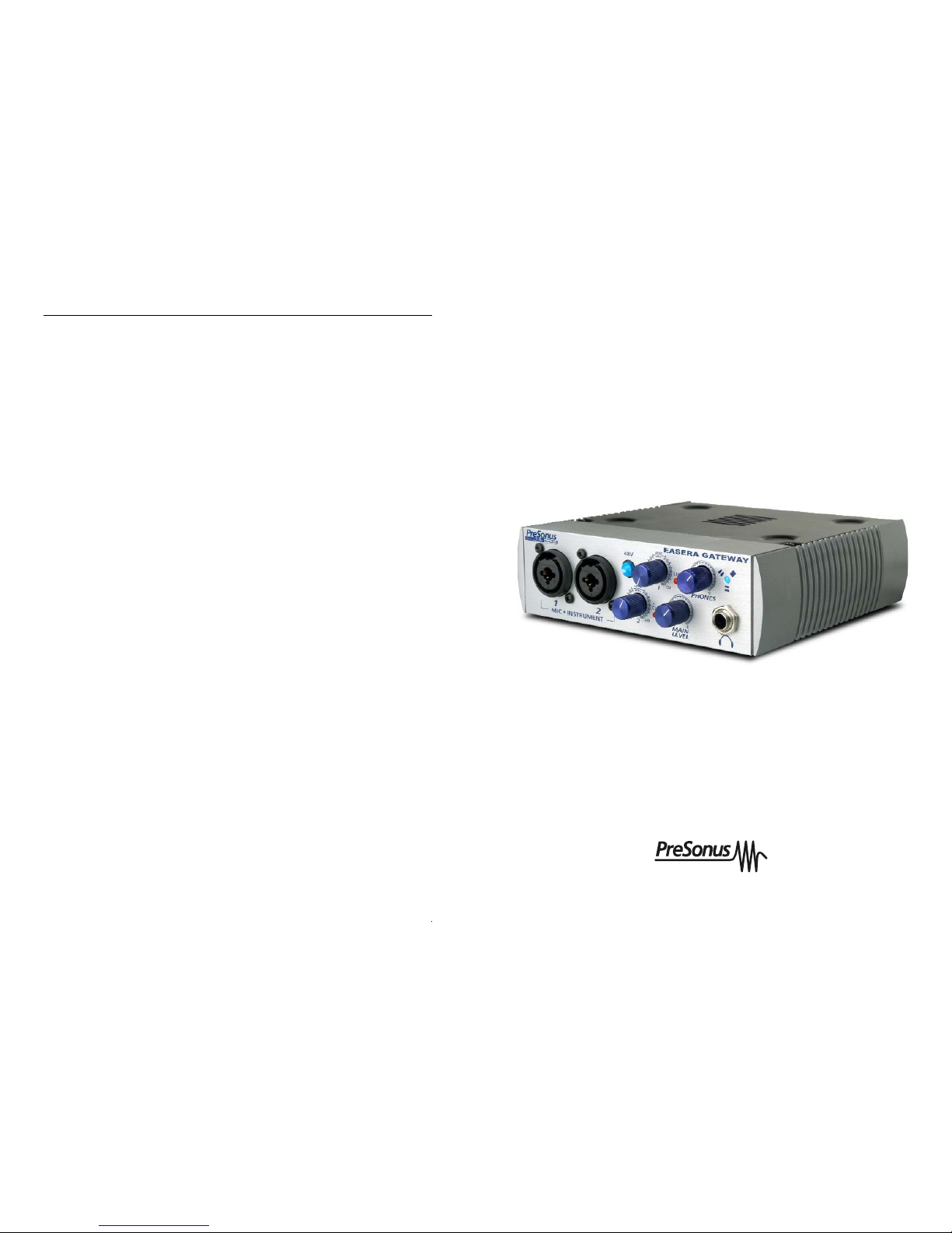
6.2 EASERA GATEWAY SPECIFICATIONS
Preamp Bandwidth 10Hz to 50kHz
Preamp Input Impedance 1.3k Ohms
Instrument Input Impedance 1M Ohms
Preamp THD <0.005%
Preamp EIN -125dB
Preamp Gain 45dB
Line Input Impedance 10k Ohms
TRS Output Impedance 51 Ohms
TRS Main Outputs Impedance 51 Ohms
Headphone Output 150mW/Ch 20Hz-20kHz
Phantom Power 48V +/- 2V
Power Supply Ext line Transformer, Internal
Switching
Bus Power Six-pin FireWire Port
Analog to Digital Converters 24-bit / up to 96khz
ADC Dynamic Range 107db
DAC 24-bit / up to 96kHz
DAC Dynamic Range 110db
IEEE1394 Speed 400mbps
As a commitment to constant improvement, PreSonus Audio Electronics, Inc. reserves the
right to change any specification stated herein at any time in the future without notification.
Users Manual
Version 1.0
PreSonus Audio Electronics, Inc.,
© 2005
DISTRIBUTED BY:
Renkus-Heinz, Inc., 19201 Cook Street, Foothill Ranch, CA 92610-3501, USA
Tel: 949-588-9997 Fax: 949-588-9514 Email: [email protected]
Web: www.renkus-heinz.com
EASERA Gateway
Data Acquisition System
6 TECHNICAL
RH583 9/06
Page 2

2
23
PreSonus Limited Warranty
PreSonus Audio Electronics Inc. warrants this product to be free of defects in material and
workmanship for a period of one year from the date of original retail purchase. This warranty is enforceable only by the original retail purchaser. To be protected by this warranty,
the purchaser must complete and return the enclosed warranty card within 14 days of purchase.
During the warranty period PreSonus shall, at its sole and absolute option, either repair or
replace, free of charge, any product that proves to be defective on inspection by PreSonus
or its authorized service representative. To obtain warranty service, the purchaser must
first call or write PreSonus at the address and telephone number printed below to obtain a
Return Authorization Number and instructions of where to return the unit for service. All
inquiries must be accompanied by a description of the problem. All authorized returns
must be sent to the PreSonus repair facility postage prepaid, insured and properly packaged. PreSonus reserves the right to update any unit returned for repair.
PreSonus reserves the right to change or improve the design of the product at any time
without prior notice. This warranty does not cover claims for damage due to abuse, neglect, alteration or attempted repair by unauthorized personnel, and is limited to failures
arising during normal use that are due to defects in material or workmanship in the product. Any implied warranties, including implied warranties of merchantability and fitness for
a particular purpose, are limited in duration to the length of this limited warranty. Some
states do not allow limitations on how long an implied warranty lasts, so the above limitation may not apply to you.
In no event will PreSonus be liable for incidental, consequential or other damages resulting from the breach of any express or implied warranty, including, among other things,
damage to property, damage based on inconvenience or on loss of use of the product,
and, to the extent permitted by law, damages for personal injury. Some states do not
allow the exclusion of limitation of incidental or consequential damages, so the above limitation or exclusion may not apply to you. This warranty gives you specific legal rights, and
you may also have other rights, which vary from state to state. This warranty only applies
to products sold and used in the United States of America. For warranty information in all
other countries please refer to your local distributor.
PreSonus Audio Electronics, Inc.
7257 Florida Blvd.
Baton Rouge, LA 70806
(225) 216-7887
(800) 750-0323
www.presonus.com
© 2005, PreSonus Audio Electronics, Incorporated. All rights reserved.
Audio Drop Outs – Can occur when the speed of your processor cannot buffer audio fast
enough. Windows XP – Try lowering your EASERA GATEWAY’s CPU to a lower setting, by
right clicking on the EASERA GATEWAY control panel icon in your system tray.
Preamplifier
Q: I have a microphone plugged into channel one (or two) but I am not getting any signal.
Possible Solutions
1. Check your microphone cable.
2. Make sure the microphone does not require phantom power. If it does press the 48 V
button.
Power Issues
Q: I just bought a EASERA GATEWAY from (dealer name goes here) in (city and state go
here) and I live in Morocco. When I plugged in my EASERA GATEWAY it caught on fire
and smoke came out of the top. What do I do?
A: PreSonus has a distributor in almost every country. Therefore, PreSonus does not
authorize or condone exportation of any of our products by US dealers. If you have done
this and your product has been damaged (more than likely due to voltage irregularities)
then you will need to return the unit to the dealer in the United States. The dealer can then
return it to PreSonus for a non-warranty repair. After the unit is repaired, the dealer will be
billed accordingly and the unit will be returned to the dealer.
WARRANTY
6 TECHNICAL
Page 3
22
3
Blue – solid sync
Red – sync not present
Flashing Red and Blue – external sync not present
Pops and clicks can also occur with high CPU loads (ie; running a large number of
plug-ins, etc) at low latency. Windows XP – try increasing your latency settings in the
EASERA GATEWAY’s hardware control panel.
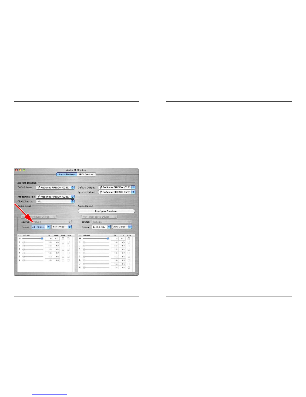
No Sync (Red) – Macintosh Users – Open Audio MIDI Setup and change the
Format sample rate speed to anything different. This will re-establish synchronization
and the Blue sync light will turn on. Once you have the blue sync light you can then
reset the Format sample rate to your desired setting.
1 Overview
1.1 Introduction 4
2 Installation and Set up
2.1 Computer Requirements 5
2.2 Installation of EASERA GATEWAY Drivers 6
2.3 EASERA GATEWAY Control Panel 7
2.4 EASERA GATEWAY Mixer 11
3 Controls & Connections
3.1 Front Panel Layout and Descriptions 12
3.2 Back Panel Layout and Descriptions 14
4 Mixer
4.1 Mixer 16
4.2 Operation of Mixer 18
5 Application Notes
5.1 Microphones 21
6 Technical
6.1 Trouble Shooting 21
6.2 Specifications 24
6 TECHNICAL TABLE OF CONTENTS
Page 4

4
21
1.1 INTRODUCTION
Thank you for purchasing the PreSonus EASERA GATEWAY. PreSonus Audio Electronics
has designed the EASERA GATEWAY utilizing high-grade components to insure optimum
performance that will last a lifetime. The EASERA GATEWAY is the most powerful recording interface of its size, with the ability to record and playback four inputs and six outputs
simultaneously at 24-bit/96K sample rate.
Loaded with four analog inputs, including two PreSonus microphone preamplifiers and two
line inputs, six balanced analog outputs and MIDI I/O, the EASERA GATEWAY is ready to
go out of the box for professional-quality computer recording. For further flexibility, the
EASERA GATEWAY can be bus-powered by a six-pin FireWire connector or externally
powered by the included power supply. The EASERA GATEWAY is the perfect computer
recording system that gives you the power for professional quality recordings in the palm
of your hand.
We suggest that you use this manual to familiarize yourself with the features, applications
and correct connection procedure for your EASERA GATEWAY before trying to connect it
to your computer. This will hopefully alleviate any unforeseen issues that you may
encounter during installation and set up.
Thank you, once again, for buying our product and we hope you enjoy your EASERA
GATEWAY!
5.1 MICROPHONES
The EASERA GATEWAY works great with all types of microphones including dynamic, ribbon and condenser microphones. Dynamic microphones and ribbon microphones are generally lower output devices and require no external power source. Condenser microphones
are generally more sensitive than dynamic and ribbon microphones and typically require
external 48V phantom power.
NOTE: If you are using a ribbon microphone, please check the manual for the mic before
applying phantom power. Applying phantom power to some microphones could cause damage to the microphone.
6.1 TROUBLE SHOOTING
Please note that many technical issues can arise when converting a standard computer
into a DAW (Digital Audio Workstation). PreSonus will only provide support for issues that
directly relate to the EASERA GATEWAY interface. It may be necessary to contact the
manufacturer of the computer, operating system and/or software to obtain additional technical support. PreSonus does not provide support for issues in regards to operating systems,
additional hardware or software.
Please check the PreSonus website, www.presonus.com regularly for software information
and updates, firmware updates, and technical support. Also, technical assistance may be
received by calling PreSonus at 225-216-7887 between the hours of 10 am and 8 PM
Central Time.
Pops and Clicks
The light on the front right panel of the EASERA GATEWAY is a clock (sync) indicator. It
lets you know if your unit is receiving word clock correctly. Word clock is the manner by
which digital devices sync frame rates. Proper word clock sync prevents digital devices
from having pops, clicks, or distortion in the audio signal (due to mismatched digital audio
transmission).
If the symbol is solid blue, this indicates that your unit is in sync with the computer.
If the light is solid red, this indicates that the EASERA GATEWAY does not have sync from
the computer and that the unit might not be connected properly.
If the unit is flashing red and blue, the unit is not receiving external sync. \
The three different light modes are repeated on the next page.
1 OVERVIEW
5 APPLICATION NOTES
6 TECHNICAL
Page 5
20
5
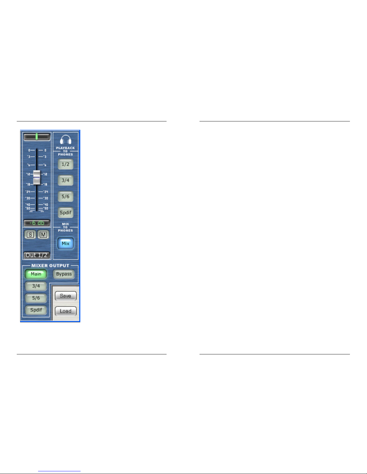
OUTPUT SECTION
Output Level (fader) – Adjusts the output
level of the mixer.
Global Solo Clear – Clears (ON) or restores
(off) solo’s that have been selected in input
channels.
Global Mute Clear – Clears (ON) or restores
(off) mute’s that have been selected in input
channels.
Playback to Phones – selects the audio
stream output coming from your software.
Mix to Phones – Pressing this button sends
the Mixer’s zero latency output to the headphones.
Mixer Output – sends the output of the mixer
to the selected pair of outputs on the
EASERA GATEWAY.
Save – enables you to save your mixer
setups.
Load – loads your mixer setups. (note that
you must first save a mixer setup before you
load o
2.1 COMPUTER REQUIREMENTS
Below are the minimum computer system requirements for your EASERA GATEWAY.
Windows
- OS: Microsoft Windows XP
- Computer: Windows compatible computer with FireWire port.
- CPU/Clock: Pentium, Celeron with 900Mhz or higher (Dual 1.2 GHz recommended)
- Memory(RAM): 256 MB (512MB recommended)
Macintosh
- OS: MacOS X 10.3.7 or later
- Computer: Apple Macintosh series with on-board Firewire port.
- CPU/Clock: PowerPC G4/800Mhz or higher (G4/Dual 1 GHZ recommended)
- Memory(RAM): 512 MB or more
Note that the speed of your processor, amount of RAM and size and speed of your hard
drive will greatly affect the overall performance of your recording system. Also, a more
powerful system (faster processor with more RAM) will allow for lower latency (signal
delay) than you might experience while monitoring audio or MIDI signals.
MIXER 2 INSTALLATION AND SETUP
Page 6
6
19
2.2 INSTALLATION OF EASERA GATEWAY DRIVERS
Windows XP
Installation Steps:
- Quit all currently running applications
- Insert CD-ROM Driver Installation included with your EASERA GATEWAY into your computer. (DO NOT CONNECT YOUR EASERA GATEWAY AT THIS TIME.)
- CD should auto run. (If not, navigate to CD and double click on Setup.exe
Carefully read and follow the EASERA GATEWAY installation instructions. The installer will
prompt you to connect your EASERA GATEWAY at the proper time.
(NOTE: If you are connecting the EASERA GATEWAY via a standard 6-pin Firewire cable,
power for the unit will be supplied via the Firewire cable. If you are using a 4 to 6-pin
Firewire cable, you will need to connect the included external power supply to power the
EASERA GATEWAY.) This installation procedure will also install the EASERA GATEWAY
Control Panel and Mixer software.
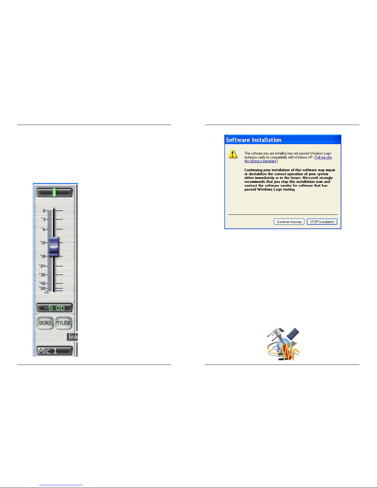
Note: If at any point during installation a “Software Installation” message appears from
Windows regarding Windows Logo testing click “Continue Anyway” to continue installation.
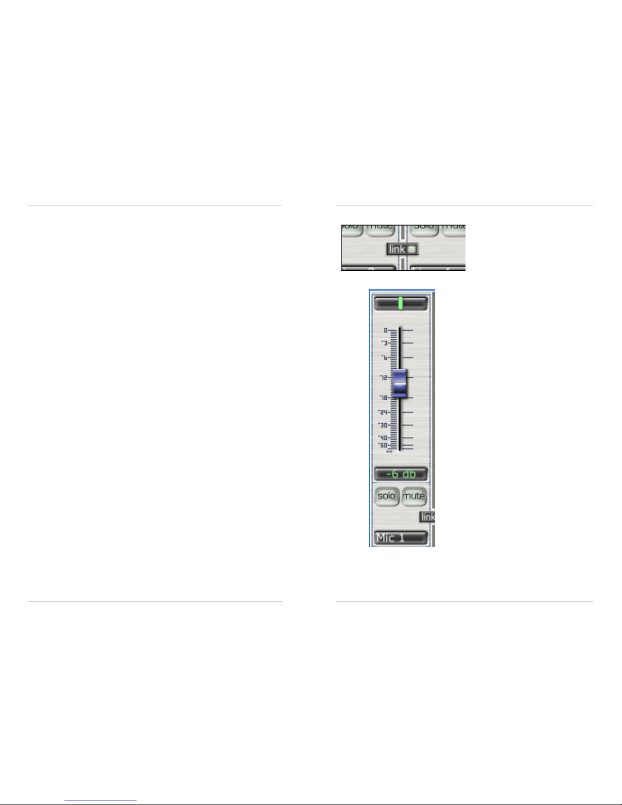
Link – links the input gain of adjacent
channels. If the two channels do not
have the same level when the link button
is pressed, clicking on one of the faders
will send the other input level to the
same level as the channel that was
clicked on.
Input (software playback channel) –
This is the audio return from your audio
software. The same functions are available as the other inputs including PAN
(balance between left and right channels), LEVEL, SOLO and MUTE. This is
a stereo channel. This channel picks up
the audio stream that is sent from your
software and enables you to mix it with
the direct input of your EASERA GATEWAY.
PLAYBACK – Indicates the stereo
stream output channels from your software.
2 INSTALLATION AND SETUP 4 MIXER
Page 7
18
7
6. In the MIXER OUTPUT section of the EASERA GATEWAY Mixer, select the pair of outputs to send out of the EASERA GATEWAY (for example studio monitors connected to outputs 1/2).
4.2 OPERATION OF MIXER
The silver tracks represent the six possible inputs from the EASERA GATEWAY as well as
the software playback. The blue section contains information on the output of the mixer.
Each input has the following functions:
Pan (green vertical line.) – You can clickdrag the pan (stereo image) of each input by
moving the green vertical line to the left or
right. Double clicking on the green line will
reset the pan to the center.
Holding down ALT or CTRL, or SHIFT while
dragging PAN, puts PAN into fine mode for
more accurate adjustment of PAN.
Level (fader) – Adjusts the input level of
each input. Double clicking on the blue fader
automatically sets the fader to full gain.
Solo – by pressing Solo, all other input channels are muted.
Mute – Mutes input channel.
Macintosh OSX (10.3.7 or later)
The audio drivers for the EASERA GATEWAY are included in the CORE AUDIO of
Macintosh OSX 10.3.7 and later.
Once you have verified that you are running OSX 10.3.7 or later, connect your EASERA
GATEWAY to a FireWire port on your computer (power for the unit will be supplied via the
Firewire cable). Your EASERA GATEWAY sync light should flash red and then stay blue to
signify that your EASERA GATEWAY is properly sync’d to your computer.
2.3 EASERA GATEWAY CONTROL PANEL
WINDOWS XP
Once you have successfully installed your audio drivers, the EASERA GATEWAY Control
Panel will be available from your system tray (typically located at the bottom right hand
corner of your screen near your clock).
2 INSTALLATION AND SETUP4 MIXER
Page 8
8
17
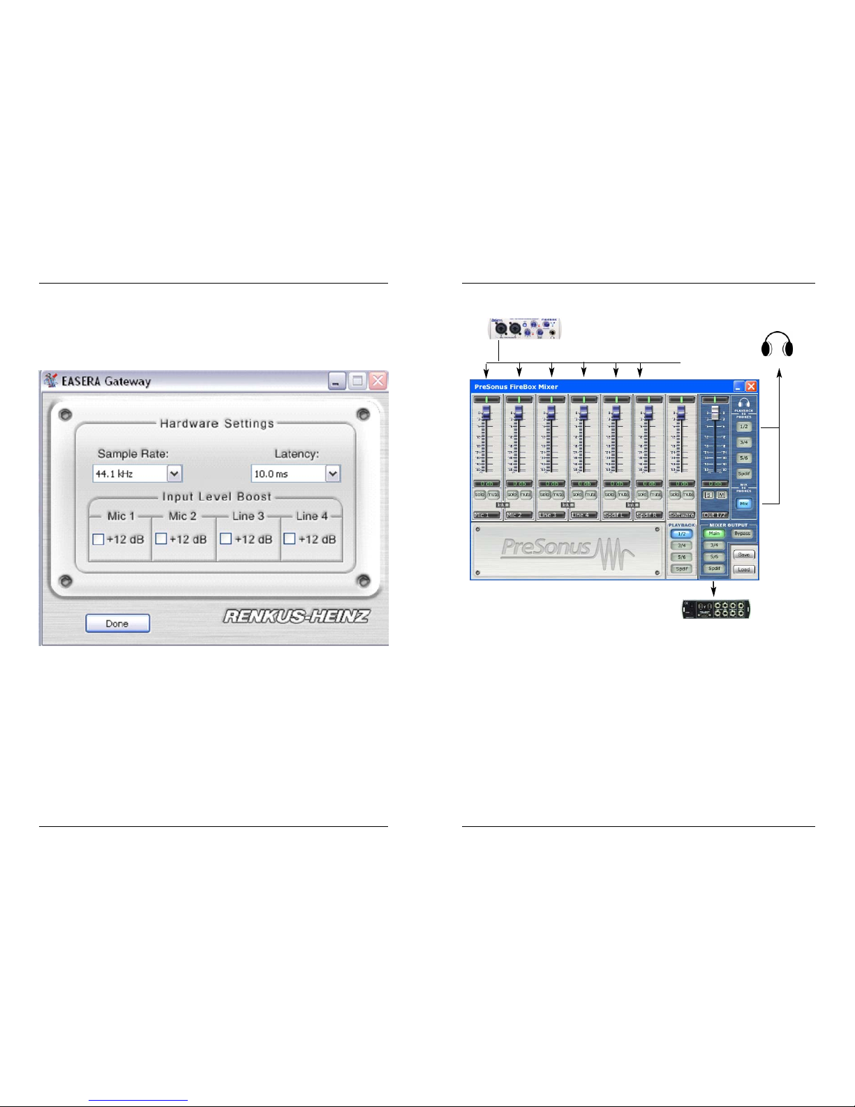
Double click on the EASERA GATEWAY Control Panel ICON to open the EASERA GATEWAY Hardware Control Panel.
EASERA GATEWAY HARDWARE CONTROL PANEL (Windows XP)
Sample Rate: Drop down the menu to select the sample rate of the EASERA GATEWAY –
either 44.1, 48, 88.2, 96k. This must be set to the same sample rate in your recording
software.
Note that when the Gateway is used with EASERA, the sample rate can also be set directly in EASERA.
EASERA GATEWAY MIXER FLOWCHART
To set up your Mixer application for zero latency recording (example):
1. Record enable your desired track – turn off input monitoring function (or mute the track)
in your software.
2.Select playback channels of the main output of your audio software in the SOFTWARE
PLAYBACK channel of the EASERA GATEWAY mixer. The input on this channel will be the
output of your software.
3.Connect your microphone to input 1 and turn on phantom power if needed.
4.You can now adjust the levels of your microphone and your software playback to your
desired levels for recording (monitoring only).
5.If using headphones select “Mix” under Mix to Phones. – this will send the output of the
Mixer to the headphone output.
2 INSTALLATION AND SETUP 4 MIXER
Mixer output to one of six
stereo outputs on EASERA
Gateway
6 inputs from the EASERA
GATEWAY go directly to:
Headphone output can be any playback stream
from your software or the mix from the mixer.
Page 9
16
9
4.1 MIXER
The EASERA GATEWAY includes a software MIXER/ROUTER for flexible monitoring and
routing of the audio signal before it hits your software program. This is helpful to avoid the
time it takes to process the audio you are recording – called latency. Therefore, you can
mix the input signal going into the EASERA GATEWAY with the playback from your software for zero latency recording and monitoring.
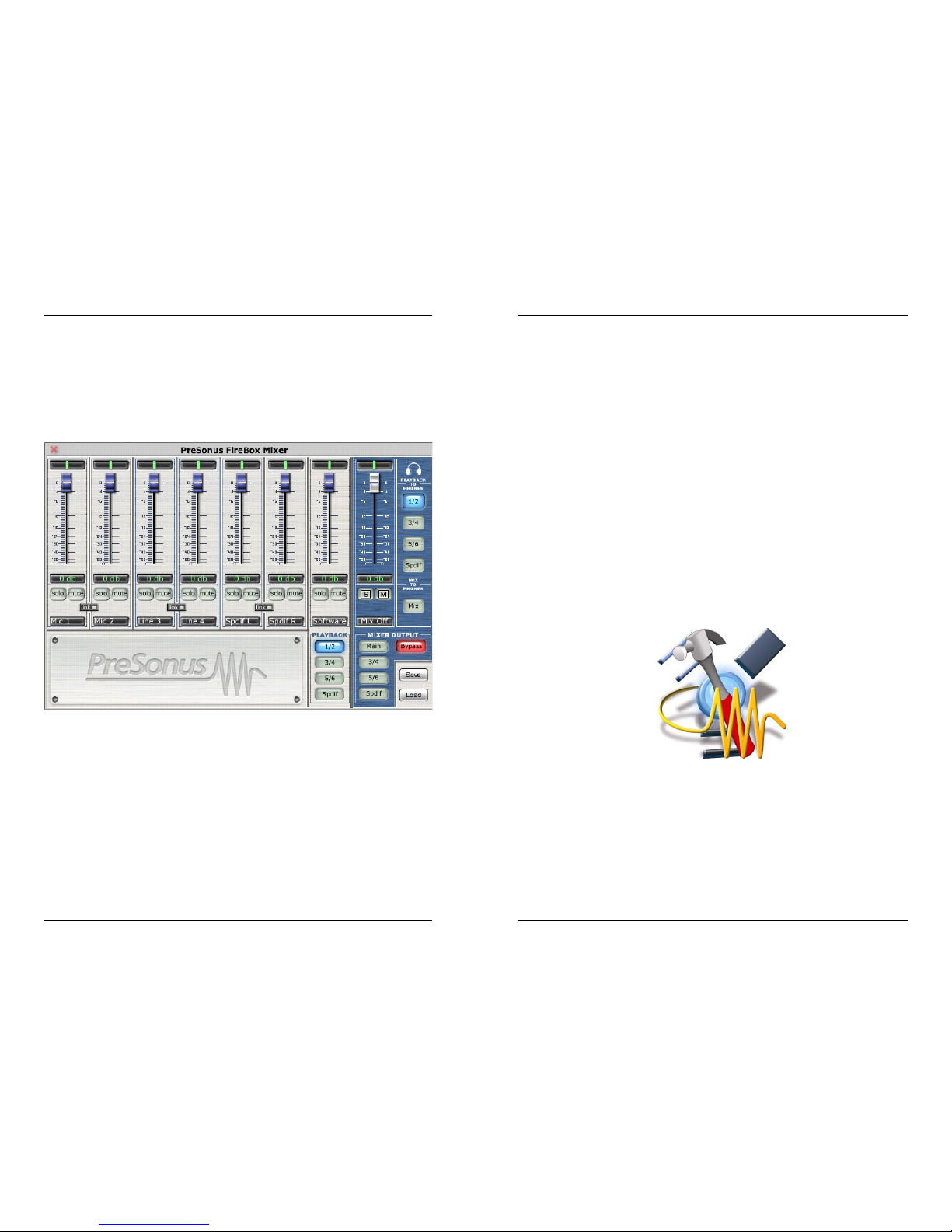
NOTE: The default settings (pictured above) for the EASERA GATEWAY mixer has all
faders set to 0dB and all pans set to center, with the Software Playback set to channels
1/2, the Mixer Output set to Bypass, and the Playback to Phones set to channels 1/2.
Clock Source: Drop down the menu to select the EASERA GATEWAY’s digital sync
source.
INTERNAL
Latency: – Sets the amount of delay time of your EASERA GATEWAY (1.5ms – 24ms).
Latency is the time it takes for the computer to process audio. Lower latency settings
demand more CPU resources. In the case of inconsistent audio, (i.e. drop outs, pops and
clicks, digital distortion, etc) we recommend that you increase this setting.
Input Level Boost: clicking this button will boost the input level of each corresponding
analog input on the EASERA GATEWAY by +12dB. Use this feature for recording quiet
instruments or devices with low output.
Macintosh - EASERA GATEWAY HARDWARE CONTROL PANEL
The included CD-ROM contains Macintosh software for the EASERA GATEWAY Control
Panel as well as the Mixer software.
To install the EASERA GATEWAY Control Panel, drag and drop the following file to your
hard drive:
EASERA GATEWAY Control
Once this file is saved to your hard drive, double click on it to launch the Control Panel.
2 INSTALLATION AND SETUP4 MIXER
Page 10
10
15
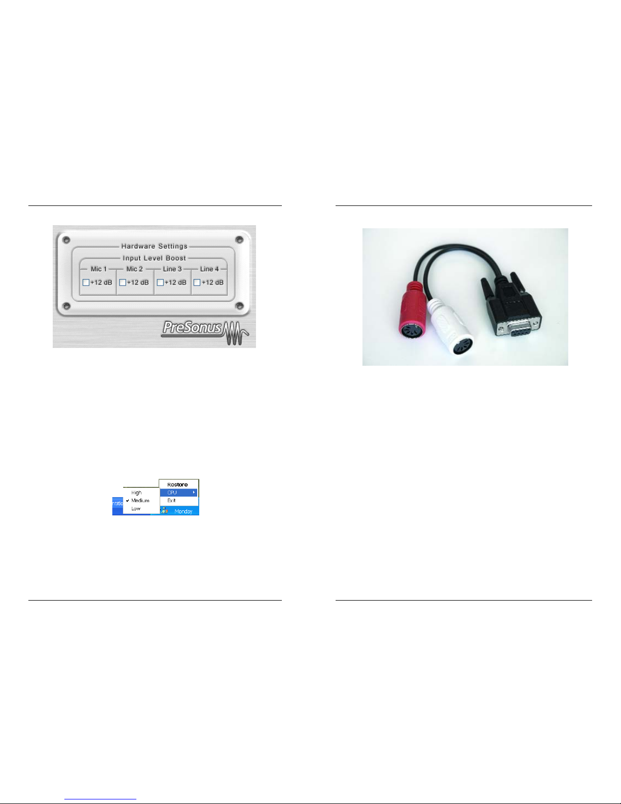
Input Level Boost: clicking this button will boost the input level of each corresponding
analog input on the EASERA GATEWAY by +12dB. Use this feature for recording quiet
instruments or devices with low output.
EASERA GATEWAY CONTROL PANEL ADVANCED SETTINGS:
You can “Right Click” on the EASERA GATEWAY control panel icon to select between
three different computer optimization settings. These settings optimize the buffers and
audio streaming settings based on the speed of your processor. If you are experiencing
audio drop outs, it is recommended that you select a lower CPU setting.
High: Computer Processor 2GHz and higher
Medium (default): Computer Processor 1GHz to 2GHz
Low: Computer Processor 800MHz to 1GHz
.
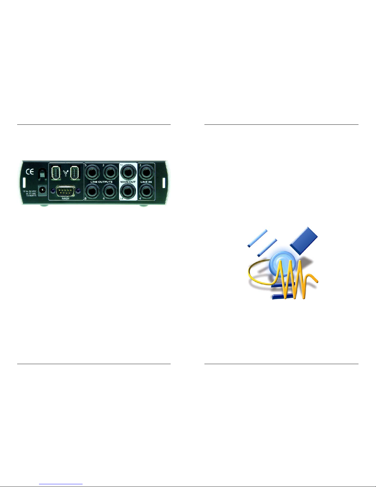
Line Outputs (3, 4, 5, 6). Balanced line level outputs. These connectors will accept
either balanced (TRS – Tip Ring Sleeve) ¼” cables or unbalanced TS (Tip Sleeve) ¼”
cables.
Main CR Output. The level of this output is controlled by the Main volume knob on the
front of the unit.
Line Inputs (3 and 4). These connectors will accept either balanced (TRS – Tip Ring
Sleeve) ¼” cables or unbalanced TS (Tip Sleeve) ¼” cables. The Line Input can also be
used as a standard line level input for devices that do not require pre-amplification (such
as a CD player, drum machine, sampler and etc.).
2 INSTALLATION AND SETUP 3 CONTROLS AND CONNECTIONS
DB9 Connector Breakout Cable
Page 11
14
11
3.2 BACK PANEL LAYOUT AND DESCRIPTION
12VDC Power Adaptor Input.
This is where you plug the provided power supply into the EASERA GATEWAY. Please
check the power supply to ensure that it is the correct voltage and plug type for your country. Note that you can also power your EASERA GATEWAY with a six-pin FireWire port
from your computer instead of using the external power supply.
FireWire Ports.
There are two firewire ports on the back of the EASERA GATEWAY. Both FireWire ports
are standard 6 pin firewire jacks. If your computer has a six-pin FireWire port you can
power your EASERA GATEWAY from the FireWire connector. If your computer has a 4 pin
connector, then you will need to get a 4 to 6 pin connector to connect your EASERA
GATEWAY to your computer, and use the external power supply. Either port can be used
to connect the EASERA GATEWAY to a FireWire port on your computer.
MIDI IN and OUT.
MIDI I/O can be connected to the Gateway using the DB-9 connector breakout cable
(included with the Gateway).
MIDI stands for “Musical Instrument Digital Interface”. However, the MIDI standard goes
well beyond just instrumentation and sequencing. The MIDI inputs and outputs allow connection and/or communication with external MIDI equipment. One function of this port is
MIDI programming. This port can also be used for MMC (MIDI Machine Control) and MTC
(MIDI Time Control). Please consult the manual of the software manufacturer to learn
setup and usage of different MIDI applications
2.4 EASERA GATEWAY MIXER
WINDOWS XP
Once you have successfully installed your audio drivers, the EASERA GATEWAY Mixer will
be available in your program files. You can launch the Mixer by clicking: Start -> Program
files -> RH_Presonus...->EASERAGATEWAY_MIXER.
(For details on the EASERA GATEWAY Mixer see chapter 4).
Macintosh
The included CD-ROM disk contains Macintosh software for the EASERA GATEWAY
Mixer.
To install the EASERA GATEWAY Mixer, drag and drop the following file to your hard drive:
EASERA GATEWAY Mixer
Once this file is saved to your hard drive, double click on it to launch the Mixer.
((For details on the EASERA GATEWAY Mixer see chapter 4)
4 MIXER4 MIXER
3 CONTROLS AND CONNECTIONS 2 INSTALLATION AND SETUP
Page 12
12 13
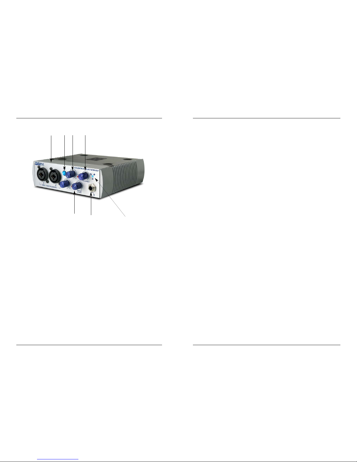
3.1 FRONT PANEL LAYOUT AND DESCRIPTION
1.Microphone / Instrument Pre-Amplifier. Your EASERA GATEWAY is equipped with
two custom designed PreSonus microphone / instrument preamplifiers for use with all
types of microphones including Dynamics, Condensers, and Ribbons as well as instruments and line level signals. The award winning PreSonus preamplifier design is a Class
A input buffer followed by a dual servo gain stage. This arrangement results in ultra low
noise and wide gain control allowing the EASERA GATEWAY user to boost desirable signal
without increasing unwanted background noise.
2. 48 Volt Phantom Power. The EASERA GATEWAY has selectable 48V Phantom power
available for both preamps.
XLR connector wiring for Phantom Power
Pin 1= GND Pin 2= +48V Pin3= +48V
+22dBu Headroom. The EASERA GATEWAY mic-pre has +22 dBu of headroom. This
feature gives you wide dynamic range and excellent transient response characteristics.
Neutrik Combo Connectors. Both preamps of the EASERA GATEWAY have a Mic/Line
connector using the Neutrik Combo connector. This revolutionary style connector lets you
use either ¼” phone or XLR connectors in the same female input.
INSTRUMENT INPUTS (Channels 1 and 2): The ¼” TS connector on channels 1 and 2
are for use with an instrument (guitar, bass, and etc.). When an instrument is plugged into
the instrument input, the microphone preamplifier is bypassed and the EASERA GATEWAY
becomes an active instrument preamplifier.
NOTE: Active instruments are those that have an internal preamp or a line level output.
Active instruments should be plugged into a line input (3 or 4) rather than into an instrument input. In other words, don’t plug an active instrument into the combo jacks on channels 1 or 2.
3. Input Gain/Trim Control. This knob provides the following gain structure for each channel:
Microphone Input XLR: 45dB of variable gain (+14dB to +55dB)
Instrument HiZ Input TS ¼” (channels 1 and 2 only): 45dB variable gain (+8dB
to +50dB)
Clip Indicator. The clip indicator will light up if your input signal from the XLR
(Mic) or ¼” (line) reaches +18dBu (0dBfs). At this level, your mic preamp/line trim
signal may not exhibit signs of clipping such as distortion. However, this level
would cause the A/D (analog to digital) converters to clip. Therefore it is highly
recommended that you do not allow your converters to clip (the clip indicators to
light up) as the sound quality would not be desirable.
4. Main Level. This knob allows control over the output level for the MAIN CR OUTPUT 1
and 2 on the back of the EASERA GATEWAY. It has a range of -80db to +10dB.
5. Headphone Symbol and ¼” Jack. This is where you connect your headphones.
6. Phones. The Phones knob controls the amount of volume going to the headphone out-
put on the front of the unit. Notice the volume indicator goes to 11 (loud). Use this setting
with caution.
7. Red-Blue Power/Sync Light. This light is a clock (sync) indicator. It lets you know if
your unit is receiving word clock correctly. Word clock is the manner by which digital
devices sync frame rates. Proper word clock sync prevents digital devices from having
pops, clicks, or distortion in the audio signal (due to mismatched digital audio transmission).
Blue – solid sync
Red – sync not present
Flashing Red and Blue – external sync not present
3 CONTROLS AND CONNECTORS 3 CONTROLS AND CONNECTORS
1
23 6
4
5
7
 Loading...