

PRESIDENT President, Thomas, William Owner's Manual
THOMAS
WILLIAM
Owner's manual
Downloaded from www.cbradio.nl
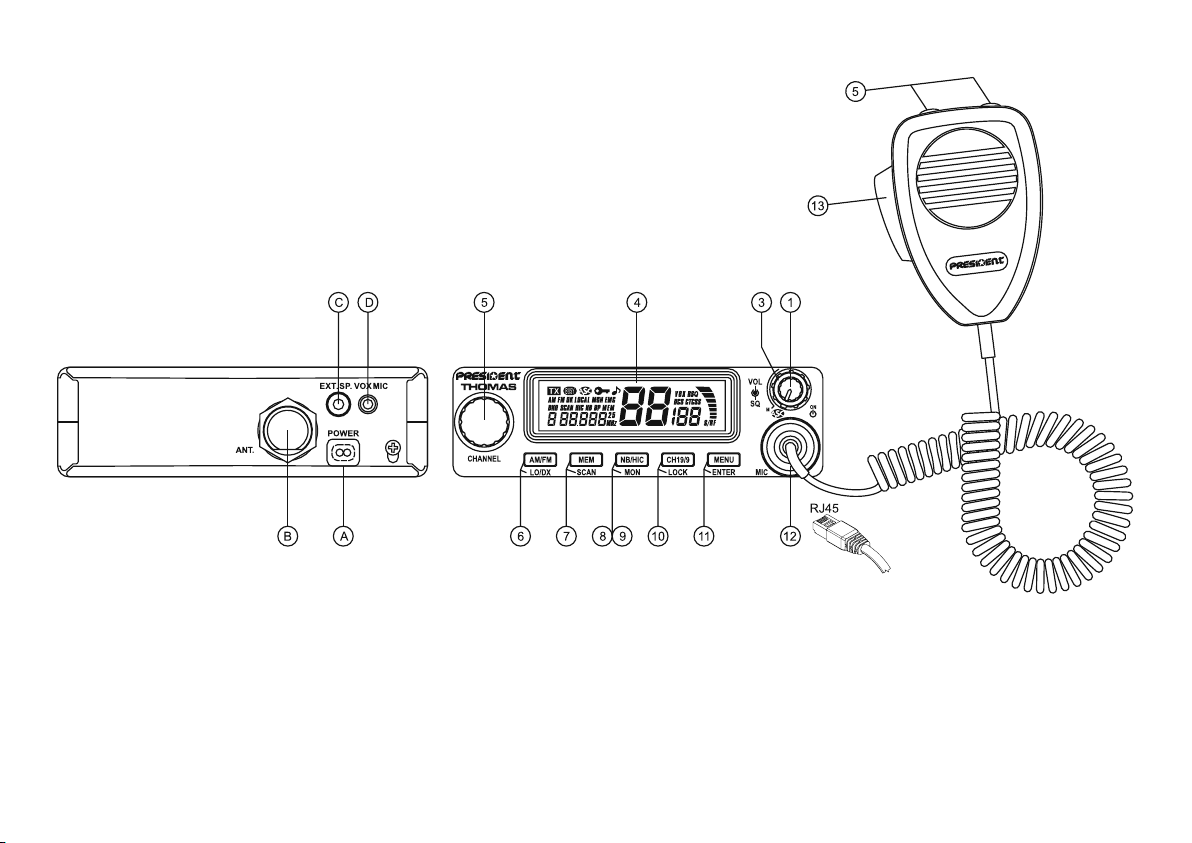
Your PRESIDENT THOMAS ASC at a glance
1 - Power and Volume knob (see page 9)
3 - Squelch knob (see page 10)
4 - Display (see page 10)
5 - Channel selector - rotary knob on the unit
s and t key on the standard microphone
(see page 11)
6 - AM/FM and LO/DX key (see page 11 and 12)
7 - MEM and SCAN key (see page 12 and 13)
8/9 - NB/HIC and MON key (see page 14)
10 - CH19/9 and LOCK key (see page 14 and 15)
11 - MENU and ENTER key (see page 15 and 16)
12 - Microphone plug - RJ45 (see page 16)
13 - PTT - Push To Talk (see page 16)
A - Power supply (see page 24)
B - Antenna connector
C - Jack for external loudspeaker
D - Jack for optional vox mike
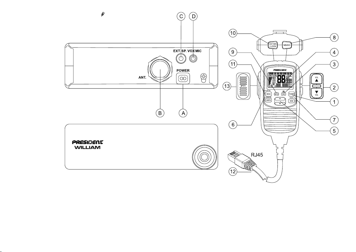
Your PRESIDENT WILLIAM ASC at a glance
1 - Power key (see page 9)
2 - Volume s and t key (see page 9)
3 - Squelch key(see page 10)
4 - Display (see page 10)
5 - Channel selector s and t key (see page 11)
6 - AM/FM and LO/DX key (see page 11 and 12)
7 - MEM and SCAN key (see page 12 and 13)
8 - NB/HIC key (see page 14)
9 - MON key (see page 14)
10 - CH19/9 and LOCK key (see page 14 and 15)
11 - MENU and ENTER key (see page 15 and 16)
12 - Microphone plug - RJ45 (see page 16)
13 - PTT - Push To Talk (see page 16)
A - Power supply (see page 24)
B - Antenna connector
C - Jack for external loudspeaker
D - Jack for optional vox mike

SUMMARY
INSTALLATION .........................................................................................................................................................................................................................6
HOW TO USE YOUR CB ..........................................................................................................................................................................................................9
TECHNICAL CHARACTERISTICS ...........................................................................................................................................................................................25
TROUBLE SHOOTING ............................................................................................................................................................................................................25
HOW TO TRANSMIT OR RECEIVE A MESSAGE ...................................................................................................................................................................25
GLOSSARY ............................................................................................................................................................................................................................26
CERTIFICATE OF CONFORMITY ...........................................................................................................................................................................................28
FREQUENCY TABLES .................................................................................................................................................................................................... 29 ~ 31
EUROPEAN NORMS .............................................................................................................................................................................................................33
WILLIAM remote microphone is optional on THOMAS.
This manual explains the features in two parts. “THOMAS ASC” and “WILLIAM ASC”. All the features
for the WILLIAM ASC or for the THOMAS ASC using the optional remote SPK/MIC are preceded by
the icon and writed using this font style.
With the WILLIAM ASC or when you use the remote microphone accessory on THOMAS ASC, two
items are added at the end of the Menu contents for adjustment of remote microphone features:
- DIMMER
- LCD CONTRAST
4
WARNING !
Before using, be careful never transmit without
first having connected the antenna (connection
"B" situated on the back panel of the equipment)
or without having set the SWR (Standing Wave
Ratio) ! Failure to do so may result in destruction
of the power amplifier, which is not covered by
the guarantee.
MULTI-NORMS TRANSCEIVER!
See Configuration setting on page 23 and
the Configuration table on page 33 .
The guarantee of this transceiver is valid only in the country of purchase.
5

Welcome to the world of the new generation of CB radios. The new PRESIDENT range gives you access to top
performance CB equipment. With the use of up-to-date
technology, which guarantees unprecedented quality,
your PRESIDENT THOMAS ASC is a new step in personal
communication and is the surest choice for the most
demanding of professional CB radio users. To ensure
that you make the most of all its capacities, we advise
you to read carefully this manual before installing and
using your PRESIDENT THOMAS ASC CB Radio.
A) INSTALLATION
1) WHERE AND HOW TO MOUNT YOUR MOBILE CB RADIO
a) You should choose the most appropriate setting from a simple and practical
point of view.
b) Your CB radio should not interfere with the driver or the passengers.
c) Remember to provide for the passing and protection of different wires (e.g.
power, antenna, accessory cabling) so that they do not interfere in any way
with the driving of the vehicle.
d) To install your equipment, use the cradle (1) and the self-tapping screws [2]
provided (drilling diameter 3.2 mm). Take care not to damage the vehicle’s
electrical system while drilling the dash board.
e) Do not forget to insert the rubber joints [3] between the CB and its support
as these have a shock-absorbing effect which permits gentle orientation
and tightening of the set.
f) Choose where to place the microphone support and remember that the
microphone cord must stretch to the driver without interfering with the controls
of the vehicle.
- N.B. : As the transceiver has a frontal microphone socket, it can be set into
the dash board. In this case, you will need to add an external loud speaker
to improve the sound quality of communications (connector EXT.SP situated
on the back panel: C). Ask your dealer for advice on mounting your CB radio.
MOUNTING DIAGRAM
6
2) ANTENNA INSTALLATION
a) Choosing your antenna
- For CB radios, the longer is antenna, the better its results. Your
dealer will be able to help you with your choice of antenna.
b) Mobile antenna
- Must be fixed to the vehicle where there is a maximum of metallic surface
(ground plane), away from windscreen mountings.
- If you already have a radio-telephone antenna installed, the CB antenna
should be higher than this.
- There are two types of antenna: pre-regulated which should be used on a
good ground plane (e.g. car roof or lid of the boot), and adjustable which
offers a much larger range and can be used on a smaller ground plane (see
p. 8 § 5, Adjustment of SWR).
- For an antenna which must be fixed by drilling, you will need a good contact
between the antenna and the ground plane. To obtain this, you should lightly
scratch the surface where the screw and tightening star are to be placed.
- Be careful not to pinch or flatten the coaxial cable (as this runs the risk of
break down and/or short-circuiting).
- Connect the antenna (B).
c) Fixed antenna
- A fixed antenna should be installed in as clear space as possible. If it is fixed
to a mast, it will perhaps be necessary to stay it, according to the laws in
force (you should seek professional advice). All PRESIDENT antennas and accessories are designed to give maximum efficiency to each CB radio within
the range.
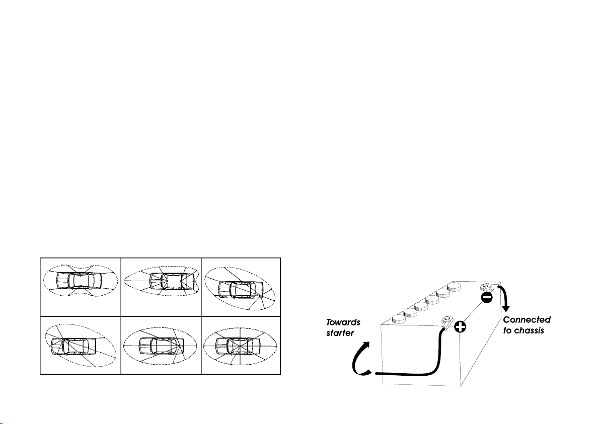
3) POWER CONNECTION
Your PRESIDENT THOMAS ASC is protected against an inversion of polarities.
However, before switching it on, you are advised to check all the connections. Your equipment must be supplied with a continued current of 12 volts
(A). Today, most cars and lorries are negative earth. You can check this by
making sure that the negative terminal of the battery is connected either to
the engine block or to the chassis. If this is not the case, you should consult
your dealer.
WARNING: Lorries generally have two batteries and an electrical installation
of 24 volts, in which case it will be necessary to insert a 24/12 volt converter
(type CV 24/12 PRESIDENT) into the electrical circuit. The following connection steps should be carried out with the power cable disconnected from
the set.
a) Check that the battery is of 12 volts.
b) Locate the positive and negative terminals of the battery (+ is red and - is
black). Should it be necessary to lengthen the power cable, you should use
the same or a superior type of cable.
c) It is necessary to connect your CB to a permanent (+) and (-). We advise
you to connect the power cable directly to the battery (as the connection
of the CB cable to the wiring of the car-radio or other parts of the electrical
circuit may, in some cases, increase the likelihood of interference).
d) Connect the red wire (+) to the positive terminal of the battery and the black
(-) wire to the negative terminal of the battery.
e) Connect the power cable to your CB radio.
OUTPUT RADIUS PATTERNS
7

WARNING: Never replace the original fuse (2 A) by one of a different
value.
4) BASIC OPERATIONS TO BE CARRIED OUT BEFORE USING
YOUR SET FOR THE FIRST TIME (without transmitting and without using the «push-to-talk» switch on the microphone)
a) Connect the microphone.
b) Check the antenna connections.
c) Turn the set on by pushing and holding the POWER knob (1).
d) Turn the squelch knob (3) to minimum (M position).
e) Adjust the volume to a comfortable level.
f) Go to Channel 20 using either the «UP» «DN» key (5) on the microphone or
the rotary knob (5).
5) ADJUSTMENT OF SWR (Standing wave ratio)
WARNING: This must be carried out when you use your CB radio for the first
time (and whenever you re-position your antenna). The adjustment must be
carried out in an obstacle-free area.
* Adjustment with an external SWR meter (e.g. TOS-1 President)
a) To connect the SWR meter :
- Connect the SWR meter between the CB radio and the antenna as close as
possible to the CB (use a maximum of 40 cm cable, type President CA 2C).
b) To adjust the SWR meter:
- Set the CB to channel 20 in FM.
- Put the switch on the SWR meter to position CAL or FWD.
- Press the «push-to-talk» switch on the microphone to transmit.
- Bring the index needle to t by using the calibration key.
- Change the switch to position SWR (reading of the SWR level). The reading on
the Meter should be as near as possible to 1. If this is not the case, re-adjust
your antenna to obtain a reading as close as possible to 1. (An SWR reading
between 1 and 1.8 is acceptable).
- It will be necessary to re-calibrate the SWR meter after each adjustment of
the antenna.
WARNING: In order to avoid any losses and attenuations in cables used for
connection between the radio and its accessories, PRESIDENT recommends
to use a cable with a length inferior to 3m.
Your CB is now ready for use.
8
B) HOW TO USE YOUR CB
1) POWER ON/OF CONTROL
Push and hold POWER knob (1).
Push and hold POWER key (1) of the remote SPK/MIC.
Power on/off is switched alternately.
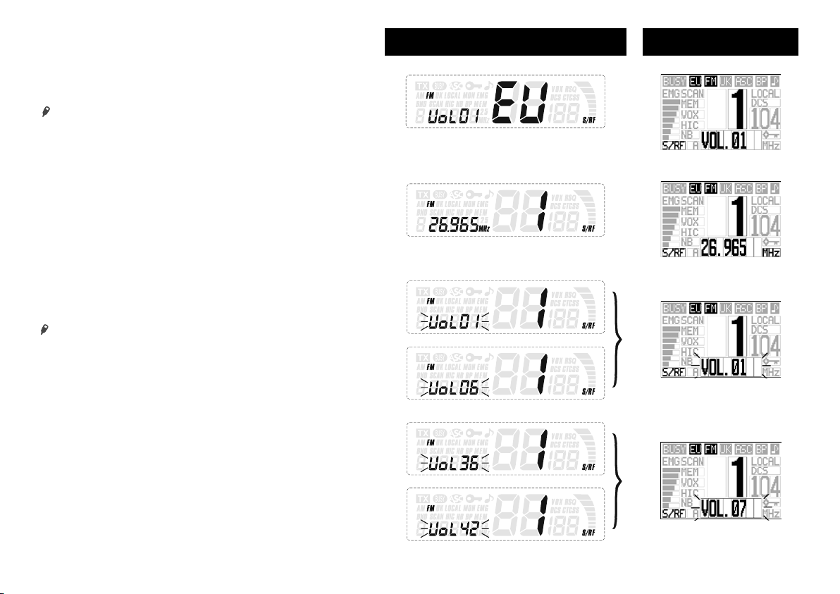
2) VOLUME CONTROL
Rotate VOL knob (1).
THOMAS ASC WILLIAM ASC
Current volume and configuration is displayed after 3 seconds
Wake up display when remote SPK/MIC is connected
Push VOL s / t key (2) of the remote SPK/MIC.
Main unit volume is 43 steps from 0 to 42. But remote SPK/MIC volume
is 8 steps from 0 to 7.
See Loudspeaker Mute page 24.
Rotate VOL knob
Rotate VOL knob
9
synch
synch
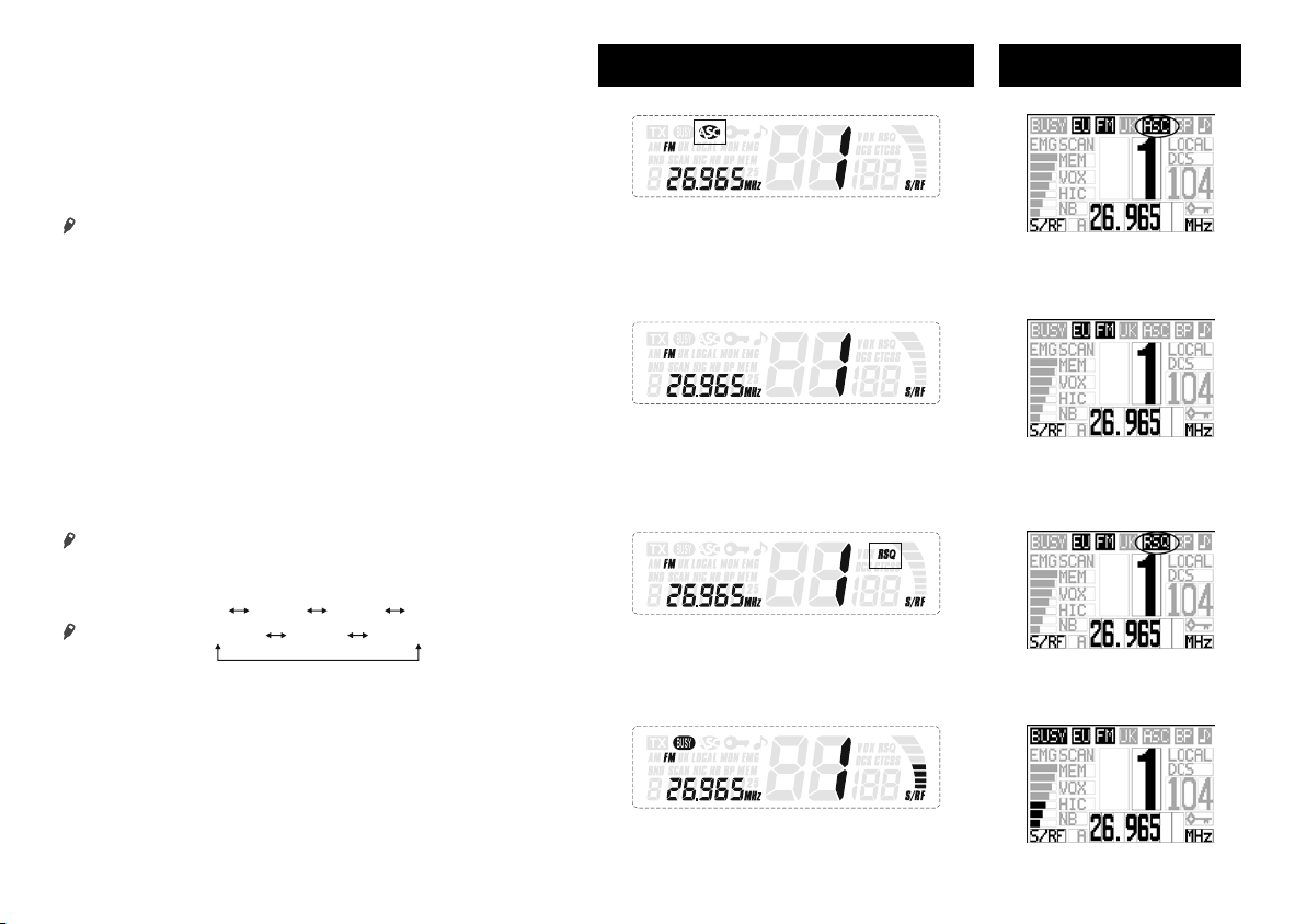
3) ASC (Automatic Squelch Control) / SQUELCH
Suppresses undesirable background noises when there is no com-
munication. Squelch does not affect neither sound nor transmission
power, but allows a considerable improvement in listening comfort.
a) ASC: AUTOMATIC SQUELCH CONTROL
Worldwide patent, a PRESIDENT exclusivity.
Turn the SQ knob (3) anti-clockwise into ASC position.
Press SQL key (3) on the remote SPK/MIC during 1,5 second
“ASC” appears on the display. No repetitive manual adjustment and
a permanent improvement between the sensitivity and the listening
comfort when ASC is active. This function can be disconnected
by turning the knob clockwise. In this case the squelch adjustment
becomes manual again. “ASC” disappears from the display.
b) MANUAL SQUELCH
Turn the SQ knob (3) clockwise to the exact point where all back-
ground noise disappears. This adjustment should be done with precision as, if set to maximum (fully clockwise), only the strongest signals
will be received. With this setting, RSQ (remote squelch function of
the remote SPK/MIC) is stopped.
c) MANUAL SQUELCH OF REMOTE SPK/MIC
Press SQL key (3) on the remote SPK/MIC. The remote squelch level is
selectable (3 levels). Push s / t key (5) to select the level. Push ENTER
(MENU) key (11) to store the setting. “RSQ” is displayed.
SQLoF
With this setting, manual squelch function of the main unit is stopped. When
the SQL level is OFF, remote squelch is inactive, “RSQ” disappears and
manual squelch knob form the unit (3) is active.
SQL-1 SQL-2 SQL-3
SQL - 1
SQL - 2 SQL - 3
THOMAS ASC WILLIAM ASC
ASC work (Automatic Squelch Control)
SQ knob is active (Analog squelch)
SQ knob is inactive. Remote SQ (=digital threshold) is active (Remote squelch RSQ)
Middle strength signal
4) S/RF METER
SRF meters indicate the receiving signal strength in RX mode.
10
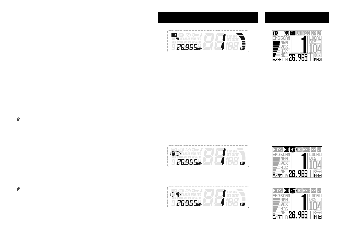
The SRF meter is used as RF power indicator in TX mode.
SRF meter indicators are 8 steps from 1 (weak) to 7 (strong), and 0
(no signal).
5) CHANNEL SELECTOR: rotary knob and UP/DN keys
of the microphone
These switches allow increasing or decreasing a channel. A «beep»
sounds each time the channel changes if the Key Beep function is
activated. See KEY BEEP function page 21.
Rotate Channel knob (5), or push and hold s / t key (5) of standard
MIC.
Push or push and hold s / t key (5) of remote SPK/MIC.
6) MODE SELECTOR AM/FM ~ LO/DX
a) MODE SELECTOR AM/FM
This switch allows selecting the AM or FM modulation. Your modula-
tion mode has to correspond to the one of your correspondent.
Amplitude modulation/AM: is for communications in areas where
there are obstacles and over medium distances.
Frequency modulation/FM: for nearby communications in flat, open
field.
Push AM/FM key (6).
Push AM/FM key (6) of the remote SPK/MIC.
AM/FM are switched alternately.
(short push)
THOMAS ASC WILLIAM ASC
Input voice
AM setting
FM setting
11
 Loading...