

PRESIDENT Randy II M, Randy II P Owner's Manual
Portable
P
or
Mobile
M
CB Radio
Owner’s manual

3
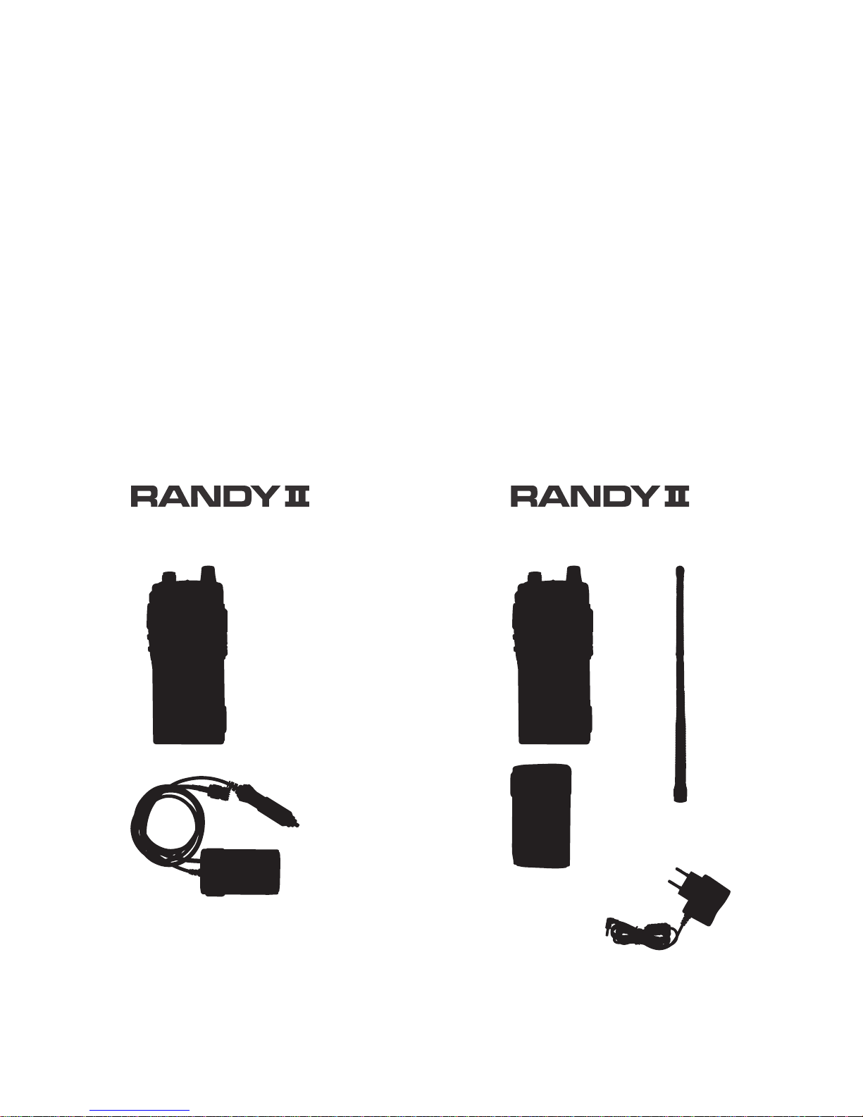
Contents:
Adapter with
CB antenna connector
and cigarette lighter plug
and Owner’s manual
Lithium-ion
rechargeable
Battery
Wall charger
and Owner’s manual
Rubber antenna
M
Mobile Configuration
P
Portable Configuration
SUMMARY
RANDY II M - MOBILE CONFIGURATION 4
RANDY II P - PORTABLE CONFIGURATION 6
CONTROL AND FUNCTION 6
LCD ICONS INDICATOR 7
FUNCTION DESCRIPTION 8
TECHNICAL CHARACTERISTICS 13
TROUBLE SHOOTING 14
HOW TO TRANSMIT OR RECEIVE A MESSAGE 14
GLOSSARY 14
CERTIFICATE OF CONFORMITY 17
FREQUENCY TABLES 18 ~ 20
NORMS - F 21
4
WARNING!
Before using, be careful never to transmit without first having connected the antenna (connection situated on the
adapter) or without having set the SWR (Standing Wave
Ratio) ! Failure to do so may result in destruction of the
power amplifier, which is not covered by the guarantee.
The guarantee of this transceiver is valid only
in the country of purchase.
MULTI-NORMS TRANSCEIVER!
See function “F” on page 12 and the Norms - F table
on page 21.
M ONLY
Welcome to the world of the new generation of CB radios. The new
PRESIDENT range gives you access to top performance CB equipment.
With the use of up-to-date technology, which guarantees unprecedented quality, your PRESIDENT RANDY II is a new step in personal
communication and is the surest choice for the most demanding of
professional CB radio users. To ensure that you make the most of all
its capacities, we advise you to read carefully this manual before
installing and using your PRESIDENT RANDY II.
A) RANDY II M - MOBILE CONFIGURATION
1) INSTALLATION
- Connect the antenna cable to the antenna connector from the adapter.
- Plug the cigarette lighter plug in the cigarette lighter socket of the car.
- Clip the adapter on the device. See page 12.
2) ANTENNA INSTALLATION
a) Choosing your antenna
- For CB radios, the longer the antenna, the better its results. Your dealer will
be able to help you with your choice of antenna.
5
b) Mobile antenna
- Must be fixed to the vehicle where there is a maximum of metallic surface
(ground plane), away from windscreen mountings.
- If you already have a radio-telephone antenna installed, the CB antenna
should be higher than this.
- There are two types of antenna: pre-regulated which should be used on a
good ground plane (e.g. car roof or lid of the boot), and adjustable which
offer a much larger range and can be used on a smaller ground plane (see
§ 4, Adjustment of SWR).
- For an antenna which must be fixed by drilling, you will need a good contact
between the antenna and the ground plane. To obtain this, you should lightly
scratch the surface where the screw and tightening star are to be placed.
- Be careful not to pinch or flatten the coaxial cable (as this runs the risk of
break down and/or short-circuiting).
- Connect the antenna to the adapter.
c) Fixed antenna
- A fixed antenna should be installed
in a clear a space as possible. If it
is fixed to a mast, it will perhaps be
necessary to stay it, according to
the laws in force (you should seek
professional advice). All PRESIDENT
antennas and accessories are designed to give maximum efficiency
to each CB radio within the range.
3) BASIC OPERATIONS TO BE CARRIED OUT BEFORE USING
YOUR SET FOR THE FIRST TIME (without transmitting and
without using the «push-to-talk» switch)
a) Check the antenna connections.
b) Turn the set on by turning the Power knob (12) clockwise.
c) Turn the squelch SQ knob (4) OFF.
d) Adjust the volume to a comfortable level.
e) Go to channel 20 by using the channel selectors (5 & 8).
4) ADJUSTMENT OF SWR (Standing wave ratio)
WARNING: This must be carried out when you use your CB radio for the first
time (and whenever you re-position your antenna). The adjustment must be
carried out in an obstacle-free area.
* Adjustment with external SWR-meter (e.g. TOS-1 PRESIDENT)
a) To connect the SWR meter:
- Connect the SWR meter between the CB radio and the antenna as close as
possible to the CB (use a maximum of 40 cm cable, type President CA 2C).
b) To adjust the SWR meter:
- Set the CB to channel 20.
- Put the switch on the SWR-meter to position CAL (calibration).
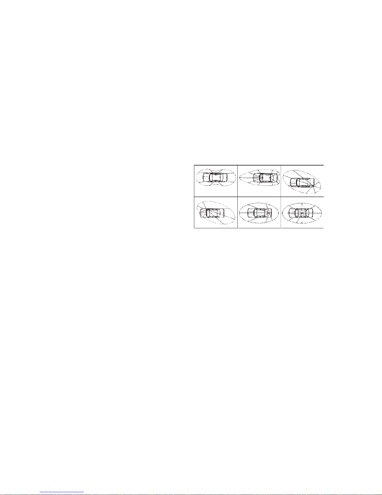
OUTPUT RADIUS PATTERN

6
- Press the «push-to-talk» switch on the microphone to transmit.
- Bring the index needle to by using the calibration key.
- Change the switch to position SWR (reading of the SWR level). The reading on
the Meter should be as near as possible to 1. If this is not the case, re-adjust
your antenna to obtain a reading as close as possible to 1. (An SWR reading
between 1 and 1.8 is acceptable).
- It will be necessary to re-calibrate the SWR meter after each adjustment of
the antenna.
Your CB is now ready for use.
B) RANDY II P - PORTABLE CONFIGURATION
1) INSTALLATION
- Screw the rubber antenna on the device.
- Clip a full charged battery on the device. See page 12.
Your CB is now ready for use.
C) CONTROLS AND FUNCTIONS
1) ANTENNA: TNC type connector
2) PTT: “Push to Talk”switch
3) F: multi functions button
4) SQ: Squelch On/Off
5) Lock / Down
/ MENU: Key lock / Decrease a channel / Enter MENU when F is held-pressed.
6) SCAN / A/F / Sc. list: Scan function / AM/FM / Edit the Scan Channel List
7) DW/ P / Lamp: Dual Watch / Priority Emergency channel / LCD backlight
8) H/L / UP s / RB : TX power switch / Increase Channel / Roger Beep
7
9) MICROPHONE: Internal microphone
10) SPEAKER: Internal speaker
11) BELT CLIP
12) POWER SWITCH & VOLUME: On/Off setting and volume adjusting
13) LED INDICATOR: The indicator lights up red when transmitting and battery
capacity (Voltage) is low. The indicator lights up green when receiving or
squelch is off.
14) BATTERY/ADAPTER LOCK
15) BATTERY (on P portable configuration) / Adapter (on M mobile configuration)
16) EXTERNAL MICROPHONE JACK
17) EXTERNAL SPEAKER JACK
18) CHARGING INPUT (on P portable configuration)
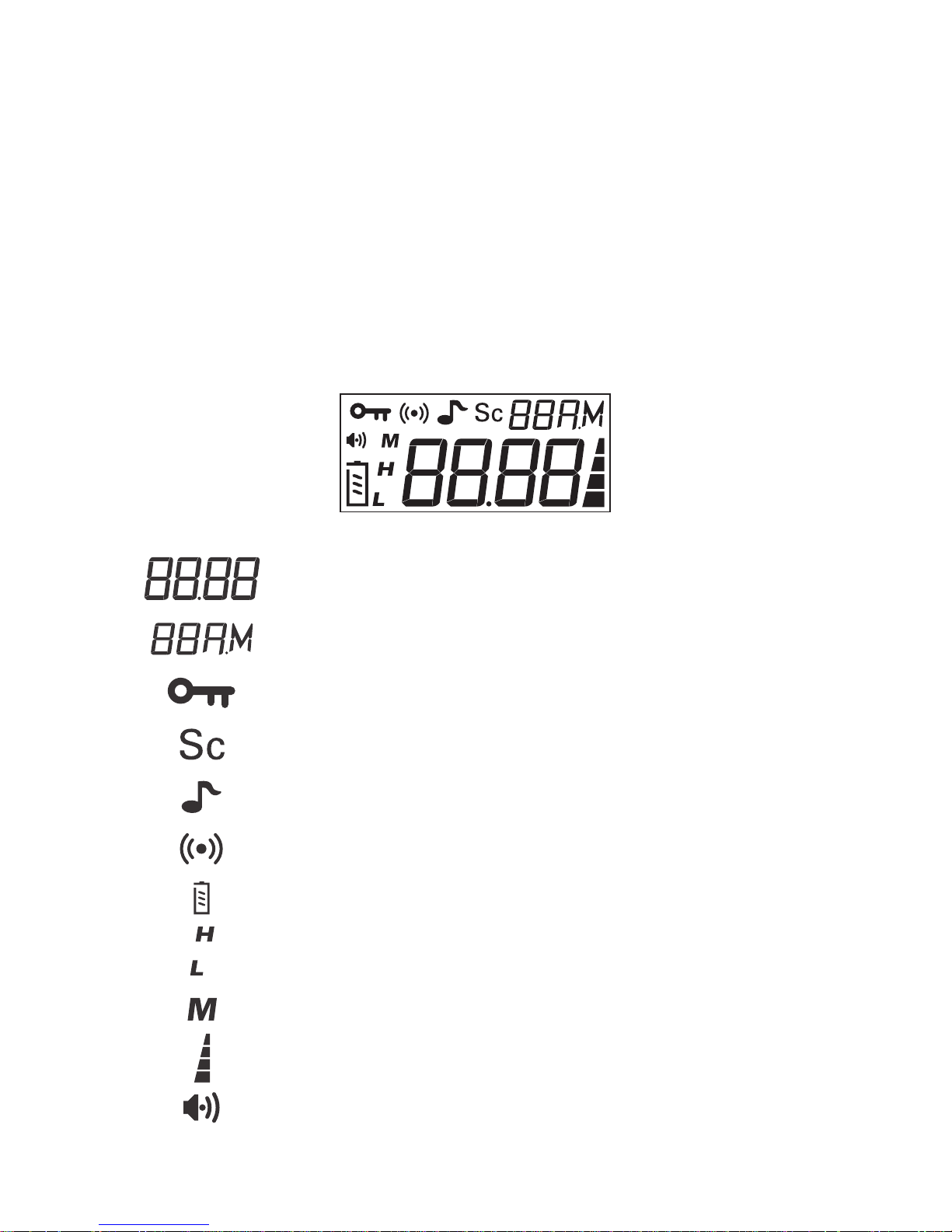
D) LCD ICONS INDICATOR
Showing working channel (CH.01) or operating country mode
Showing the AM or FM mode
Appears when keypad is locked
Appears when the channel selected is in the scanning list
Appears when Roger Beep Tone is on
Appears when Emergency Channel is on
Battery level, showing the battery capacity (voltage)
Showing transmitter output power (H=high, L=low)
Indicating the “MENU” function
Receiving signal level indicator / transmitting indicator
Show Rx receiving signal
8
E) FUNCTION DESCRIPTION
1) ON/OFF – VOLUME
- Turn On/Off-Volume knob (12) clockwise for setting the unit on and increase
the volume. Every time the radio is switched on, the display will show the
active band for 3 seconds. Turn On/Off-Volume knob (12) anticlockwise for
decreasing the volume and setting the unit off.
2) CHANNEL SELECTOR: s / t keys
- Press t (5) or s (8) button to decrease or increase a channel.
3) KEY LOCK
- Press t (5) more than 3 seconds for setting the Key lock on or off.
- When key lock is on, the icon is displayed and all keys are locked except
PTT (2).
4) DISPLAY BACK LIGHT
- Pressing F (3) + P (7) buttons to set the display backlight on or off.
- When the display backlight is set on, the lightning time is 10 seconds.
- Every time a button is pressed, except PTT (2), the lightning time is for more
10 seconds,
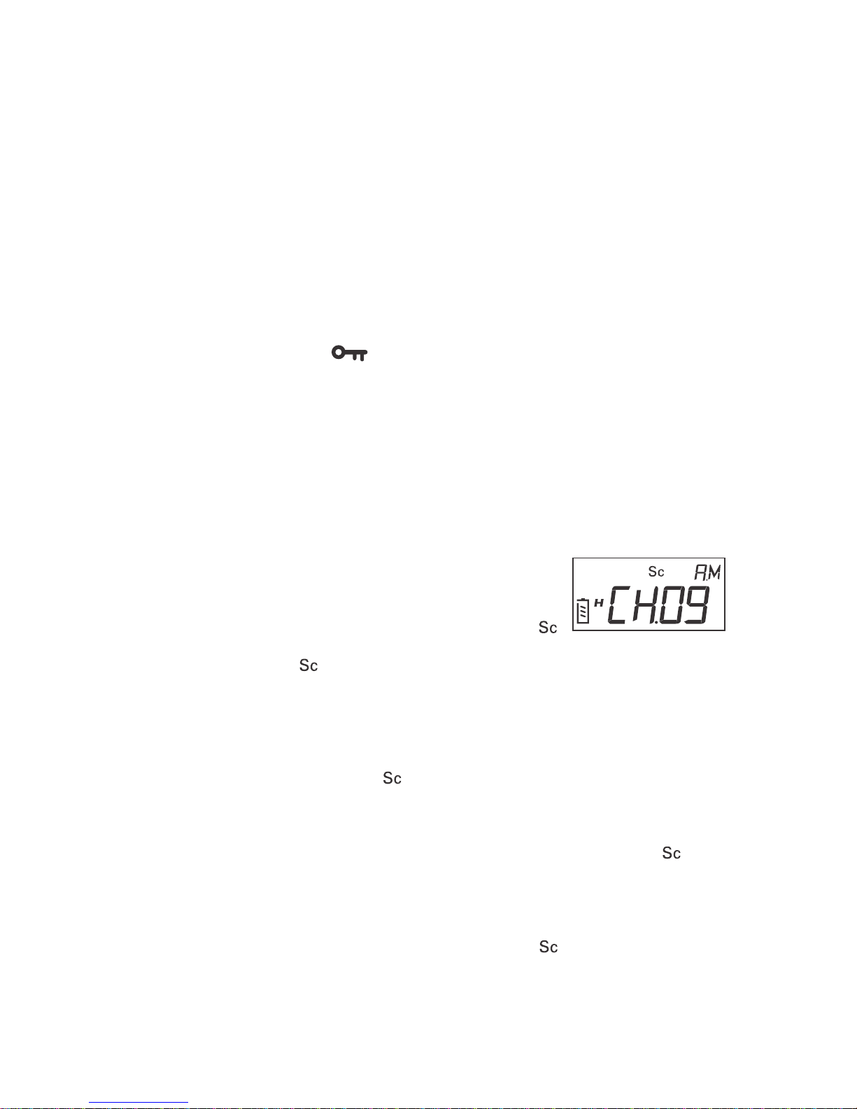
5) SCAN FUNCTION
5.1 Scan Channel List
Before operating the scan function, users have to edit
one channel, besides the default priority channel, in
scan list. Channels at scan list are marked with “
” icon on the display. The channels at the scanning list are scanned when
scanning and the “ ” icon blink.
5.2 Adding a channel to the scanning list
- Select a channel with s or t button to choose the channel that you want
set.
- Press F (3) + A/F (6) buttons to add the channel to scan list.
- The channel is the list have a “ ” icon displayed.
5.3 Deleting a channel from the scanning list
- Select a channel with s or t button.
- Press F (3) + A/F (6) buttons to delete the channel from the list. The “ ” icon
disappears.
5.4 Scanning On/Off
- Press A/F (6) button more than 3 seconds for begin to scan. The transceiver
start to scroll through the channels in scan list (the “ ” icon start blinking). It
could scan minimum 5 channels per second.
- When signal received, it will stop at that channel and you can hear voice
from speaker. When signal disappears, it will continue to scan after 5 seconds.
 Loading...