

PRESIDENT jonson II Owner's Manual

Manuel d'utilisation / Manual del usuario
Owner's manual / Handbuch
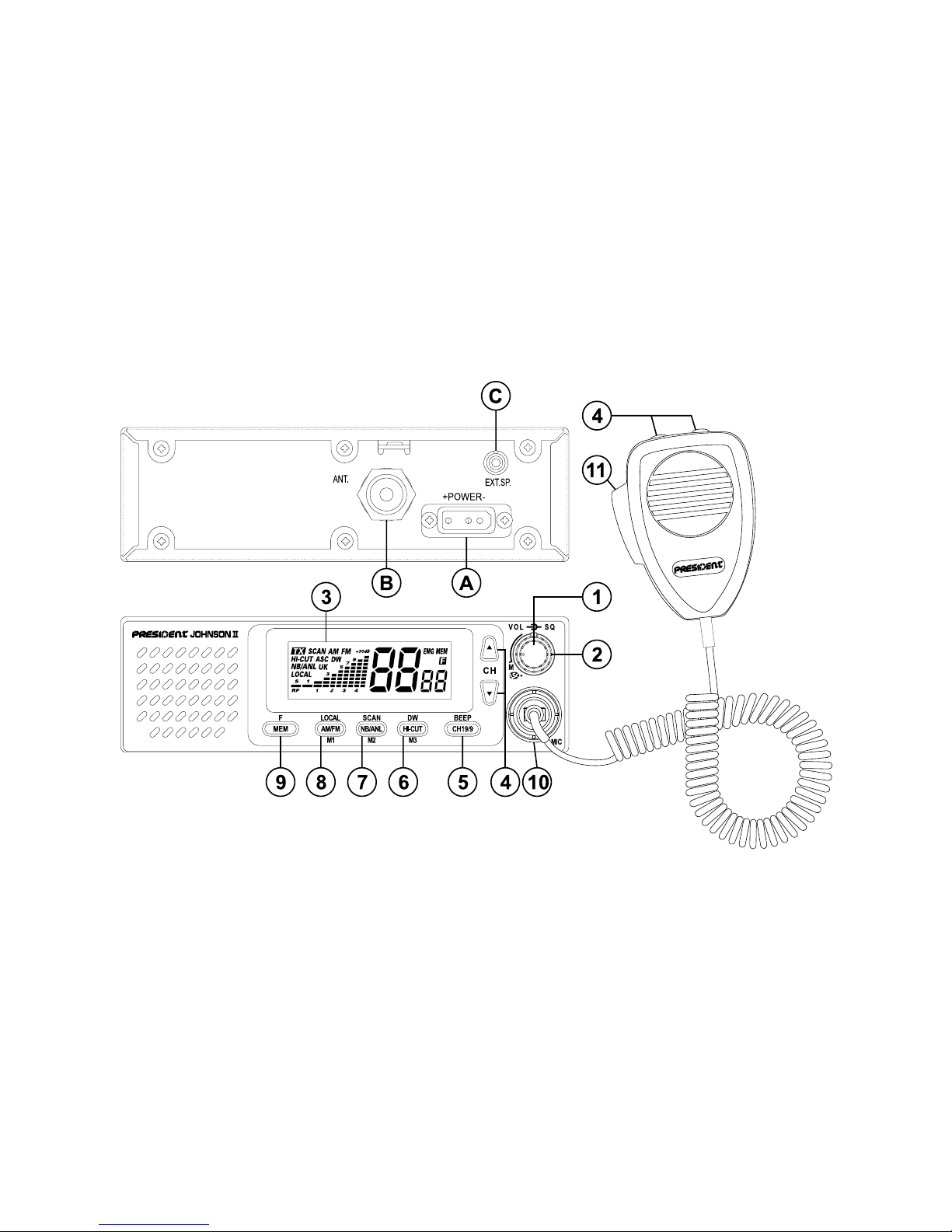
Votre PRESIDENT JOHNSON II ASC en un coup d'œil Un vistazo a vuestro PRESIDENT JOHNSON II ASC
Ihr PRESIDENT JOHNSON II ASC auf einen BlickYour PRESIDENT JOHNSON II ASC at a glance

3
SOMMAIRE
INSTALLATION 5
UTILISATION 7
CARACTÉRISTIQUES TECHNIQUES 10
GUIDE DE DÉPANNAGE 10
COMMENT ÉMETTRE/RECEVOIR UN MESSAGE 10
GLOSSAIRE 11
DÉCLARATION DE CONFORMITÉ 12
GARANTIE 14
TABLEAUX DES FRÉQUENCES 47 ~ 49
TABLEAU DES NORMES EUROPÉENNES 50
Français
SUMARIO
INSTALACIÓN 17
UTILIZACIÓN 19
CARACTERÍSTICAS TÉCNICAS 22
GUÍA DE PROBLEMAS 22
COMO EMITIR O RECIBIR UN MENSAJE 22
LÉXICO 23
DECLARACIÓN CE DE CONFORMIDAD 24
GARANTÍA 26
TABLAS DE FRECUENCIAS 47 ~ 49
NORMAS EUROPEAS 50
Español
English
Deutsch
SUMMARY
INSTALLATION 29
HOW TO USE YOUR CB 31
TECHNICAL CHARACTERISTICS 34
TROUBLE SHOOTING 34
HOW TO TRANSMIT OR RECEIVE A MESSAGE 34
GLOSSARY 35
CERTIFICATE OF CONFORMITY 36
FREQUENCY TABLES 47 ~ 49
EUROPEAN NORMS 50
INHALTSANGABE
INSTALLATION 39
BEDIENUNG 41
TECHNISCHE DATEN 44
BEI PROBLEMEN 44
TIPS FÜR DEN FUNKVERKEHR 44
BEURTEILUNG DER EMPFANGSQUALITÄT 45
KONFORMITÄTSERKLÄRUNG 46
CB-KANÄLE UND IHRE FREQUENZEN 47 ~ 49
EUROPÄISCH NORMEN 50

28
English
WARNING !
MULTI-NORMS TRANSCEIVER!
Before using, be careful never to transmit without first having connected the antenna (connection "B" situated on the back panel of the
equipment) or without having set the SWR
(Standing Wave Ratio) ! Failure to do so may
result in destruction of the power amplifier, which
is not covered by the guarantee.
See function “F” on page 33 and the Con-
figuration table on page 50.
29
English
Welcome to the world of the new generation of CB
radios. The new PRESIDENT range gives you access to
top performance CB equipment. With the use of up-todate technology, which guarantees unprecedented
quality, your PRESIDENT JOHNSON II ASC is a new step in
personal communication and is the surest choice for the
most demanding of professional CB radio users. To
ensure that you make the most of all its capacities, we
advise you to read carefully this manual before installing
and using your PRESIDENT JOHNSON II ASC.
A) INSTALLATION:
1) WHERE AND HOW TO MOUNT YOUR MOBILE CB RADIO:
a) You should choose the most appropriate setting from a simple and practical
point of view.
b) Your CB radio should not interfere with the driver or the passengers.
c) Remember to provide for the passing and protection of different wires (e.g.
power, antenna, accessory cabling) so that they do not in any way interfere
with the driving of the vehicle.
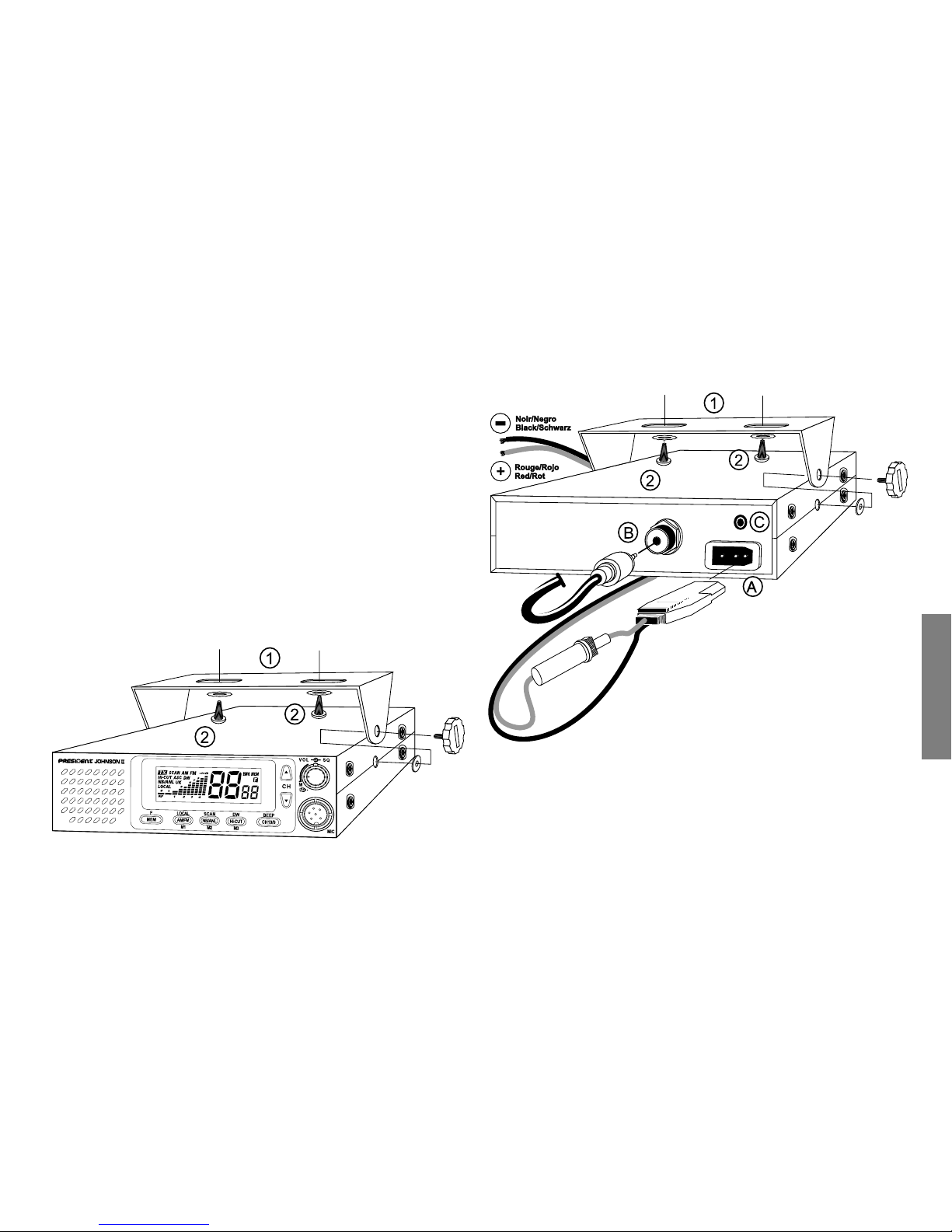
d) To install your equipment, use the cradle (1) and the self-tapping screws [2]
provided (drilling diameter 3.2 mm). Take care not to damage the vehicle’s
electrical system while drilling the dash board.
e) Choose where to place the microphone support and remember that the
microphone cord must stretch to the driver without interfering with the
controls of the vehicle.
MOUNTING DIAGRAM
30
English
2) ANTENNA INSTALLATION:
a) Choosing your antenna:
- For CB radios, the longer the antenna, the better its results. Your dealer will
be able to help you with your choice of antenna.
b) Mobile antenna:
- Must be fixed to the vehicle where there is a maximum of metallic surface
(ground plane), away from windscreen mountings.
- If you already have a radio-telephone antenna installed, the CB antenna
should be higher than this.
- There are two types of antenna: pre-regulated which should be used on a
good ground plane (e.g. car roof or lid of the boot), and adjustable which
offer a much larger range and can be used on a smaller ground plane (see
p. 31 § 5, Adjustment of SWR).
- For an antenna which must be fixed by drilling, you will need a good contact
between the antenna and the ground plane. To obtain this, you should lightly
scratch the surface where the screw and tightening star are to be placed.
- Be careful not to pinch or flatten the coaxial cable (as this runs the risk of break
down and/or short circuiting).
- Connect the antenna (B).
c) Fixed antenna:
- A fixed antenna should be installed in a clear a space as possible. If it is fixed
to a mast, it will perhaps be necessary to stay it, according to the laws in force
(you should seek professional advice). All PRESIDENT antennas and accessories are designed to give maximum efficiency to each CB radio within the
range.
3) POWER CONNECTION:
Your PRESIDENT JOHNSON II ASC is protected against an inversion of polarities.
However, before switching it on, you are advised to check all the connections. Your equipment must be supplied with a continued current of 12 volts
(A). Today, most cars and lorries are negative earth. You can check this by
making sure that the negative terminal of the battery is connected either to
the engine block or to the chassis. If this is not the case, you should consult your
dealer.
WARNING: Lorries generally have two batteries and an electrical installation
of 24 volts, in which case it will be necessary to insert a 24/12 volt converter
(type CV 24/12 PRESIDENT) into the electrical circuit. The following connection
steps should be carried out with the power cable disconnected from the set.
a) Check that the battery is of 12 volts.
b) Locate the positive and negative terminals of the battery (+ is red and - is
black). Should it be necessary to lengthen the power cable, you should use
the same or a superior type of cable.
c) It is necessary to connect your CB to a permanent (+) and (-). We advise you
to connect the power cable directly to the battery (as the connection of the
CB cable to the wiring of the car-radio or other parts of the electrical circuit
may, in somecases, increase the likelihood of interference).
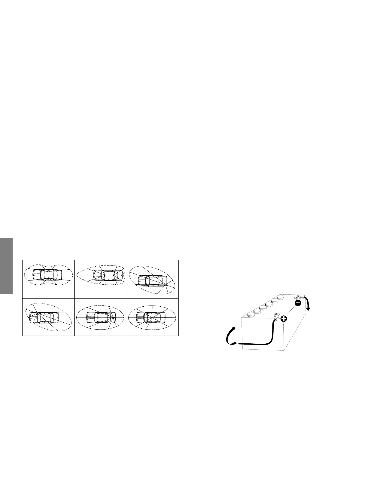
d) Connect the red wire (+) to the positive terminal of the battery and the black
(-) wire to the negative terminal of the battery.
e) Connect the power cable to your CB radio.
WARNING: Never replace the original fuse (2 A) by one of a different value.
OUTPUT RADIUS PATTERNS
Zum
chassis
Connected
to chassis
Zum
starter
Towards
starter
 Loading...