

Page 1
Instruction
IMPORTANT SAFETY INFORMATION. READ AND FOLLOW ALL SAFETY INSTRUCTIONS. Follow label information and instructions
. Do not
er at
d to
avoid potential electric shock or other potential hazard. Product must be mounted in locations and at heights and in a manner
The use of accessory
k light
, screens or
INSTALLATION INSTRUCTIONS
Thermal insulation may be installed in direct contact with the fixture, but DO NOT install insulation in
on or
Use only those trims, lamps, and maximum wattages proper for this fixture, as indicated on the label
within the housing (
or
installed in accordance with any instructions included in the listing or labeling”. Use only Prescolite UL listed trims.
3 (b)
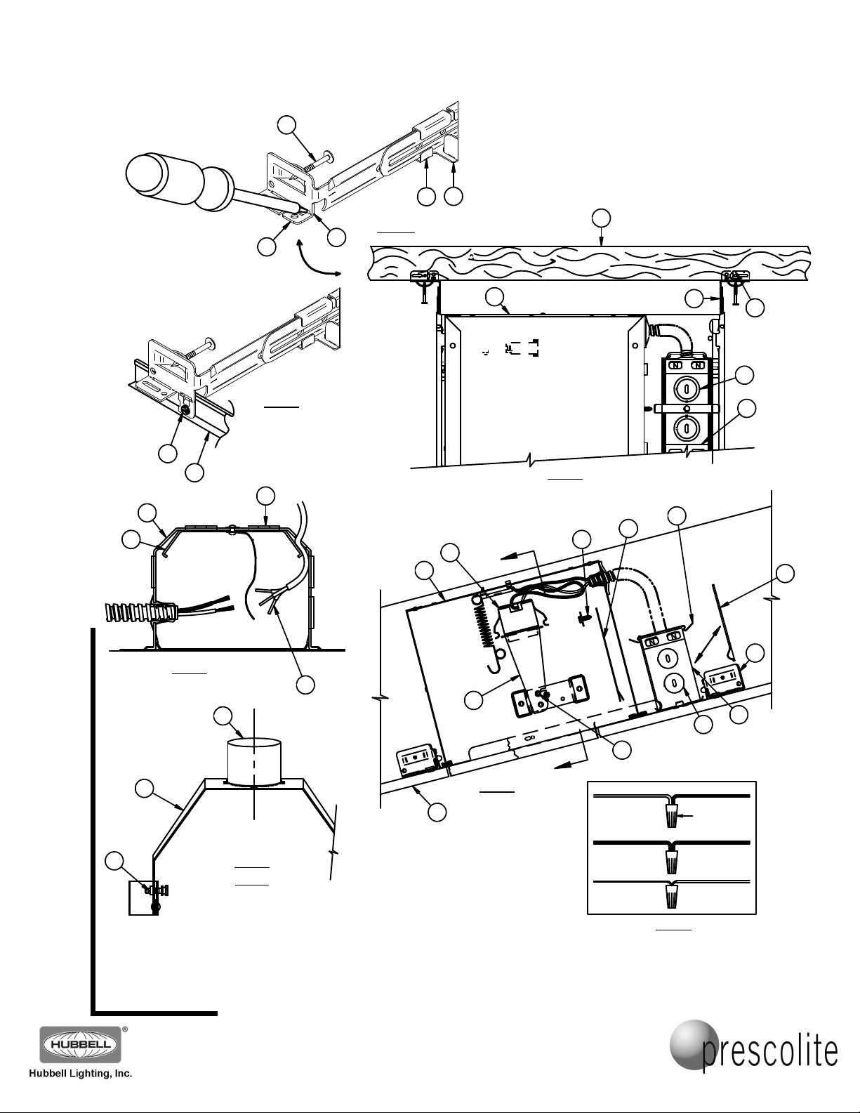
2. For Suspended Ceilings: Place the Fixture on the ceiling grid with the "T" Bars (9) running through the Bar Hanger
Set Screws are also provided
Sheet
Part No...........................................
concerning Wet or Damp Locations, installation near combustible materials, insulation, building materials, and proper lamping
install in areas subject to combustible vapors or gases. Before wiring to power supply and during servicing or relamping, turn off pow
fuse or circuit breaker. All servicing or relamping must be performed by qualified service personnel. Product must be grounde
consistent with its intended use, and in compliance with the National Electrical Code and local codes.
equipment not recommended by the manufacturer or installed contrary to instructions may cause an unsafe condition. Do not bloc
emanating from product in whole or part, as this may cause an unsafe condition. Do not allow items such as drapes, curtains
the like to come into contact with the product or to block light from the product, as this may cause an unsafe condition.
93010073
Sheet 1 of 2
SCIBX
WARNING:
excess of eight inches deep above fixture. Greater depth may cause the thermal protector to cycle the fixture
off.
WARNING:
WARNING: National Electrical Code, Article 110-3 (b), states that “Listed or labeled equipment shall be used
Use of other trims not listed in this fixture, including those that are UL classified, is a violation of N.E.C. 110and voids all warranties.
WARNING: This product contains chemicals known to the State of California to cause cancer, birth defects, and/or
other reproductive harm. Thoroughly wash your hands after installing, handling, cleaning, or otherwise touching this
product.
WARNING: If any special control devices are used with this fixture, follow the instructions carefully to assure full
compliance with N.E.C. requirements. If there are any questions, contact a qualified electrical contractor.
1. For Wooden Joists: Extend the Bar Hangers (6), use joist alignment tabs (4) to locate fixture and position
underneath the support joist (8). Drive the 4 Nails (7) into Joists (8) (Fig. 1). Drive additional nails through holes in
Bar Hanger for alternate support if required.
3).
www.prescolite.com
Prescolite Toll Free Technical Support
Notches (10). Using a flat head screwdriver or other tool, bend the integral t-bar mounting tabs (11) downward to a
vertical position (Fig. 3). Secure housing to the support structure with tie wire (supplied by others) in the holes
supplied. Sheetmetal screws (supplied by others) can also be used in the holes supplied (20).
3. Locate Housing along Bar Hanger in desired position and, using pliers, squeeze the 4 Locking Tabs (12) on the
Plaster Frame (13) tightly over the Bar Hangers to prevent further Housing movement.
that can be tightened to lock the housing position on the Bar Hangers.
4. As desired, hanger bars (6) may be shortened at score mark to fit tight mounting conditions and joist alignment
tabs removed to adjust vertically as needed by breaking off with pliers.
5. Unsnap Junction Box Cover (14) by lifting the Leaf Spring (24).
6. Run supply wires through UL Listed connectors (not supplied) in one of the five Pryouts (15) on the Junction Box
(16) or Type NM cable (ROMEX) through an Opening above the Wire Retaining Plate (17). Connect Supply Wires
(19) as shown in Fig 4 & 5. Replace Cover.
7. Adjust position of socket (21) by loosening thumbscrew (26) and rotating bracket socket (18). Retighten
thumbscrew (Fig.7).
8. FOR AIR-TIGHT APPLICATIONS: This Prescolite product is Air-Tight approved per ASTM E283 testing
standards and complies with Washington State Energy Code Requirements. To complete the installation of this AirTight product, the opening between the housing (3) and drywall ceiling (22) must be sealed by the installer using
silicone caulking, tape, or any other means acceptable to the local codes official. Prescolite accessory gasket kit G6
(purchased separately) can be used for this purpose (Fig. 6).
9. Select a Trim from the Wattage Label inside the Housing. Use Only Lamp Types approved for the Trim chosen.
DO NOT EXCEED MAXIMUM LISTED WATTAGE(S)!
10. To gain access to junction box (16) after ceiling is finished, remove screw (2) and access door (5) inside of
fixture. Junction box cover plate (14) can now be removed for service.
INSTRUCTION SHEET MUST BE REMOVED FROM FIXTURE PRIOR TO ENERGIZING.
1.888.PRS.4TEC
Hours: 8am - 5pm ET
701 Millennium Blvd., Greenville, SC 29607
With representatives offices in principal cities throughout North America.
Copyright , revision, All Rights Reserved - Printed in U.S.A.
2012 09/25/12
Page 2
Instruction
Ceiling Opening is to be 6
-
7/8”
in diameter.
11
Part No...........................................
93010073
Sheet 2 of 2
www.prescolite.com
7
13
12
10
FIG.2
8
Sheet
17
16
20
FIG.4
13
6
4
Prescolite Toll Free Technical Support
15
FIG.3
9
15
21
3
19
21
"A"
18
FIG.1
2
5
24
15
16
16
14
6
1.888.PRS.4TEC
26
18
22
FIG.7
"A-A"
701 Millennium Blvd., Greenville, SC 29607
With representatives offices in principal cities throughout North America.
Copyright , revision, All Rights Reserved - Printed in U.S.A.
2012 09/25/12
FIG.6
"A"
26
WHITE SUPPLY
WIRE FIXTURE WIRE
WIRE FIXTURE WIRE
BARE, OR GREEN
GROUND WIRE
FROM SUPPLY
WHITE OR IDENTIFIED
PLAIN OR BLACKBLACK SUPPLY
BARE, OR GREEN
FIXTURE GROUND
FIG.5
UL LISTED
WIRE NUTS
WIRE
Hours: 8am - 5pm ET
 Loading...