

Page 1

InstructionSheet
TANT SAFETY INFORMATION. READ AND FOLLOW ALL SAFETY INSTRUCTIONS. Follow label information and instructions concerning wet or
IMPOR
damp locations, installation near combustible insulation or building materials, and proper lamping. Do not install in areas subject to combustible vapors or
gases. Before wiring to power supply and during servicing or relamping, turn of
formed by qualified service personnel. Product must be grounded to avoid potential electric shock or other potential hazard. Product must be mounted in
locations and at heights and in a manner consistent with its intended use, and in compliance with the National Electrical Code and local codes. The use of
accessory equipment not recommended by the manufacturer or installed contrary to instructions may cause an unsafe condition. Do not block light ema
nating from product in whole or part, as this may cause an unsafe condition. Do not allow items such as drapes, curtains, screens or the like to come into
contact with the product or to block light from the product, as this may cause an unsafe condition.
Instruction Sheet No. . . . . . . . . . . . . . . . . . . . . . . . . .15980
Part No. . . . . . . . . . . . . . . . . . . . . . . . . . . . . . . . . . . .FT6CF
www.prescolite.com • Prescolite TollFree Technical Support 1.888.PRS.4TEC • Hours: 8am - 5pm ET
f power at fuse or circuit breaker. All servicing or relamping must be per-
-
WARNING 1: - If any special control devices are used with this fixture, follow the instructions carefully to assure full compliance with N.E.C. requirments.
If there are any questions, contact a qualified electrical contractor
ARNING 2:
W
WARNING 3: The National Electrical Code, Article 110-3 (b), states that "Listed or Labeled equipment shall be used or installed in accordance with any
instructions included in the listing or labeling". Use only with Prescolite UL
UL classified, is a violation of N.E.C. 110-3 (b) and voids all warranties.
ARNING 4:
W
Use only those trims, lamps and maximum wattages proper for this fixture, as indicated on the label within the fixture housing.
FT6CF is a type non-ic fixture. Insulation must be kept at least 3" from fixture sides to prevent lamp cycling.
.
listed trims. Use of other trims not listed in this fixture, including those that are
INSTALLATION INSTRUCTIONS
FT6CF
When installed according to the instructions provided, the Prescolite fixtures listed above will maintain the fire resistance of
UL classified Non-IC L500 series fire rated assemblies rated 1 hour or less.
Follow this Instruction Sheet Carefully. Be sure Electricity is OFF before starting Installation.
INSTALLATION IN WOOD JOISTS
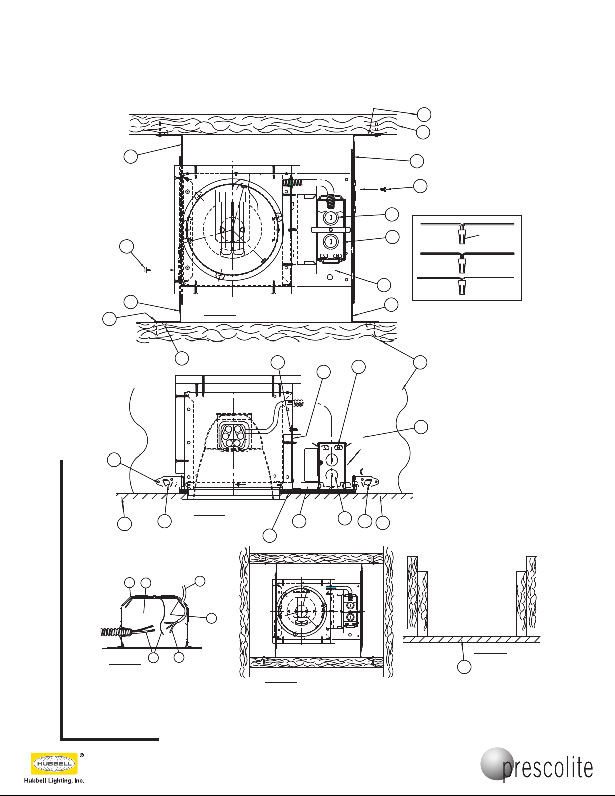
1. Slip Bar Hangers (1) through Slots in Plaster Frame (2). Hold Frame (2) in desired position between Joists (3) and drive
Bar Hanger Tabs (4) into Joists. Use a minimum 1" lg. steel Nail or Screw (24) through Holes in Bar Hanger ends for
additional support (REQUIRED). Tighten Bar Hanger Locking Screws (5) in ends of Plaster Frame (2) to prevent lateral
movement of Plaster Frame. (See Fig.1 and 2)
2. Remove Cover Plate (9) from Junction Box (10). Slip Type NM Cable (Romex)(11) through desired hole in Junction Box
(10) above Retaining Plate (13). Cable (11) is secured by Retaining Plate (13) (See Fig. 3).
3. If other than Type NM Cable (Romex) is to be used, remove One Large Knockout (15) at desired location on Top or
Sides of Junction Box (10). Bring appropriate Electrical Supply Cable into Junction Box and secure in place with proper
UL listed Connector (NOT FURNISHED).
4. Connect Fixture Wires (6) to Supply Wires (16) as shown in Wiring Diagram. Use UL listed Wirenuts (NOT FURNISHED).
5. To gain access to Junction Box (10) after Ceiling is finished, remove Screw (21) and Access Door (22) located inside
Fixture. Junction Box Cover Plate (9) can now be removed for service.
6. Plaster Frame (2) and Gasket (25) must be in contact with Ceiling (23).
7. If furring strips are used, Plaster Frame (2) must be lowered until Gasket (25) contacts Ceiling (23). (See Fig. 4. & 5
for alternate mounting methods).
(Ceiling opening is to be 6 7/8" Diam.)
This instruction sheet is also intended to be used as a paint shield.
sheet up and insert it up into the housing to protect the socket and labels from being spray painted.
101 Corporate Drive • Spartanburg, SC 29303
With representatives of
Copyright 2005, 09/05 revision, All Rights Reserved - Printed in U.S.A.
fices in principal cities throughout North
America.
Upon completion of installation, crumple this
Page 2
UL LISTED
WIRE
WIRENUTS
WIRE
WHITE SUPPLY
WIRE
GROUND WIRE
FROM SUPPLY
BLACK SUPPLY
BARE, OR GREEN
FIXTURE WIRE
FIXTURE WIRE
PLAIN OR BLACK
BARE, OR GREEN
FIXTURE GROUND
WHITE OR IDENTIFIED
Fig. 4
4
3
1
5
15
1
10
3
9
10
22
21
Fig. 1
2
1
5
1
4
24
Fig. 5
23
4
15
2
Fig. 2
25
11
13
23
4
1
9
10
23
16
6
Fig. 3
InstructionSheet
Instruction Sheet No. . . . . . . . . . . . . . . . . . . . . . . . . .15980
Part No. . . . . . . . . . . . . . . . . . . . . . . . . . . . . . . . . . . .FT6CF
www.prescolite.com • Prescolite TollFree Technical Support 1.888.PRS.4TEC • Hours: 8am - 5pm ET
101 Corporate Drive • Spartanburg, SC 29303
Copyright 2005, 09/05 revision, All Rights Reserved - Printed in U.S.A.
With representatives of
fices in principal cities throughout North
America.
Page 3
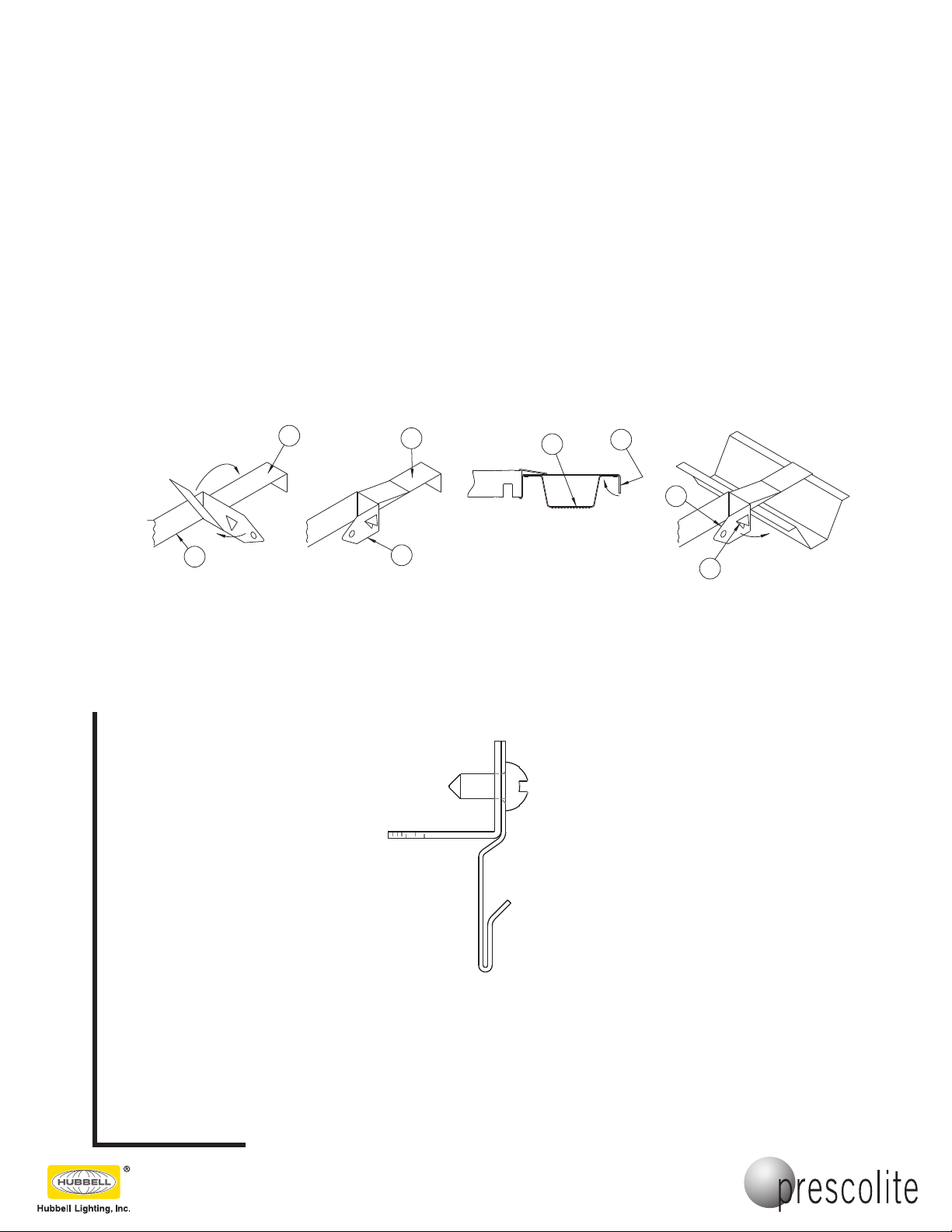
Fig. 10Fig. 9Fig. 7 Fig. 8
2
1
38
41
40
39
37
36
37
36
InstructionSheet
Installation Instructions for the Prescolite FTFCC Furring Channel Clips
(included) to be used in fire rated applications using Furring Channels
1. Attach one Furring Channel Bracket (36) to each Hanger Bar (37) as shown in Fig. 7 and 8. CAUTION: Maintain
a firm hold on Luminaire until Steps 2 and 3 are complete.
2. Lift Luminaire (30) to position Furring Channel Brackets over Furring Channels (38) and secure in place by bend
ing Tabs (39) over as shown in Fig. 9.
3. Once all Brackets are in place bend Hanger Bar End (40) around to secure Brackets to the Channels as shown
in Figure 10. NOTE: Nailer Tab (41) should lodge under edge of Furring Channel.
4. Tighten bar hanger Locking Screws (5) in ends of Plaster Frame (2) to prevent lateral movement of the Frame.
5. Install two No. 12 SWG Galv. Steel Hanger Wires (34) secured to each end of Luminaire (30) plaster frame at
Lanced Openings (35) in hanger bar support channels. Steel Hanger Wires to be installed vertically and secured to
structural members of floor or roof assembly. (See Fig. 6)
6. See Steps 2 through 6 on Page 1 to complete installation.
Instruction Sheet No. . . . . . . . . . . . . . . . . . . . . . . . . .15980
Part No. . . . . . . . . . . . . . . . . . . . . . . . . . . . . . . . . . . .FT6CF
www.prescolite.com • Prescolite TollFree Technical Support 1.888.PRS.4TEC • Hours: 8am - 5pm ET
-
Torsion spring retention brackets are shipped pre-assembled for 5/8" thick ceilings. When FT6CF is installed in ceilngs using two layers of 5/8" sheetrock, remove and reassemble as shown below.
101 Corporate Drive • Spartanburg, SC 29303
With representatives of
Copyright 2005, 09/05 revision, All Rights Reserved - Printed in U.S.A.
fices in principal cities throughout North
America.
 Loading...