

Page 1

BLOUNT PRODUCT PROTECTION PLAN
TO THE OPERATOR
PRENTICE Feller Bunchers
Exclusively For PRENTICE Models 2470, 2570, 2670 FELLER BUNCHERS, Blount, Inc., Forestry and
Industrial Equipment Division (BLOUNT) provides the following warranty subject to all of the terms and conditions
stated in this Product Protection Plan.
1 Year/2000 Hour Total Machine Coverage
The Product Protection Plan covers all parts (except as noted below) for a period of 12 months or 2000 hours,
whichever occurs first, from the validation start date. If any part is found, under normal use and service, to be
defective in factory materials or workmanship, BLOUNT will, at its sole option, repair or replace such part and will
pay labor charges as specified in the Product Protection Plan Handbook at an authorized PRENTICE dealer.
3 Year/6000 Hour Center Joint Coverage
The product Protection Plan will cover the articulation joint, including pin and bearings, for a period of 3 years or
6000 hours, whichever occurs first, from the validation start date.
This Product Protection Plan does not cover the following parts not manufactured by BLOUNT: engines, batteries,
tires, filters, hydraulic oil, other fluids or chemicals, lights, starting devices, alternators, and standard hardware
(including but not limited to nuts and bolts), accessories and vendor supplied attachments (even if such attachments
are installed by BLOUNT at its factory). Such parts may be covered by warranties of the manufacturers of such
parts. Parts that are not proven to the satisfaction of BLOUNT to be defective in factory materials or workmanship
will not be covered. This Product Protection Plan does not cover machine transportation costs or freight charges on
replacement parts. This Product Protection Plan does not cover attachments; there is a separate protection plan for
such attachments.
This Product Protection Plan does not apply to scheduled maintenance service, or to normal replacement of service
and wear items (includingbutnotlimitedtoenginetuneups,hydraulicpressurechecksoradjustments,andoilandfilterchanges, pins,andbushings).
The obligation of BLOUNT to honor claims under this Protection Plan is subject to the following conditions: The
machine installation must be approved by an authorized PRENTICE dealer. The owner must give timely notification
of a claim to an authorized PRENTICE dealer and make the product available for repair. This Product Protection
Plan shall be invalid if the machine installation is disapproved by Factory Service Personnel. The machine MUST be
maintained according to the Scheduled/Periodic Maintenance Services as outlined in the Operator’s Manual
utilizing genuine PRENTICE authorized parts. Failure to use authorized parts may impair the safety, performance
and durability of the machine and will void this Protection Plan. BLOUNT reserves the right to deny reimbursement
for any part that is not a PRENTICE authorized replacement part unless BLOUNT factory approval is obtained first.
Equipment must have been used only for its intended purpose, appropriate applications, and must not have been
altered, mistreated, or reworked in any manner whatsoever unless BLOUNTíS Engineering Department has given
prior written approval to an Authorized PRENTICE Dealer. This Product Protection Plan does not cover any part
that has been abused, misused, contaminated or operated under conditions other than those specified by BLOUNT.
Any operationaboveratedandpublishedcapacityorimproperapplicationorusewillvoidthisProductProtectionPlan. .
The Protection Plan covers only new equipment shipped from BLOUNTíS factory and sold to the original purchaser
of the machine. It is transferable to sequential owners providing the following two (2) conditions are met and
documented by an authorized PRENTICE dealer.
1. The original BLOUNT warranty has not yet expired; and
2. A transfer fee has been paid to BLOUNT accompanied by photographs of the machine and a complete Warranty
Registration form statingthe new ownerís name and address.
There are no other obligations or liabilities on the part of BLOUNT except for this written Product Protection
Plan. THERE ARE NO OTHER WARRANTIES, EXPRESS OR IMPLIED; THERE IS NO IMPLIED
WARRANTY OF MERCHANTABILITY AND NO IMPLIED WARRANTY OF FITNESS FOR A
PARTICULAR PURPOSE. No one, including any dealer, is authorized to assume for or on behalf of
BLOUNT any different or additional obligations in connection with BLOUNTíS products. BLOUNT’S
liability under this Product Protection Plan is limited exclusively to the remedies stated in this Product
Protection Plan and is subject to all the conditions set forth herein. BLOUNT assumes no other liabilities,
express or implied, arising in contract, tort or otherwise. BLOUNT expressly disclaims any liability for lost
time, commercial loss or any other incidental or consequential damages of any kind.
Effective Date: August 9, 2006
2570/2670 0806
i
Page 2

TO THE OPERATOR
BLOUNT PRODUCT PROTECTION PLAN
Exclusively for PRENTICE Attachments
For its PRENTICE brand name attachments, Blount, Inc., Forestry and Industrial Equipment Division (BLOUNT)
provides the following warranty subject to all of the terms and conditions stated in this Product Protection Plan.
1 Year/2000 Hour Total Attachment Coverage
The Product Protection Plan covers all parts (except as noted below) for a period of 12 months or 2000 hours,
whichever occurs first, from the validation start date. A Blount authorized dealer must approve each attachment
installation. If any part is found under normal use and service to be defective in factory materials or workmanship,
BLOUNT will, at its sole option, repair or replace such part and will pay labor charges as specified in the Product
Protection Plan Handbook at a Blount authorized dealer.
This Product Protection Plan does not cover the following parts not manufactured by BLOUNT: engines, batteries,
tires, filters, hydraulic oil, other fluids or chemicals, lights, starting devices, alternators, standard hardware (nuts,
bolts, etc.), accessories and vendor supplied attachments (even if such attachments are installed by BLOUNT at its
factory). Such parts may be covered by warranties of the manufacturers of such parts. Parts that are not proven to the
satisfaction of BLOUNT to be defective in factory materials or workmanship will not be covered. The Product
Protection Plan does not cover attachment transportation costs or freight charges on replacement parts. BLOUNT
reserves the right to deny reimbursement for any part that is not a BLOUNT authorized replacement part.
The Product Protection Plan does not apply to scheduled maintenance service (such as engine tune-ups, hydraulic
pressure checks or adjustments, oil changes, etc.) or to normal replacement of service and wear items (pins,
bushings, etc.).
Equipment must have been used only for its intended purpose, appropriate applications, and must not have been
altered, mistreated, or reworked in any manner whatsoever unless BLOUNTís Engineering Department has given
prior written approval to an Authorized Blount Dealer. This Product Protection Plan does not cover any part that has
been abused, misused, contaminated or operated under conditions other than those specified by BLOUNT.
Anyoperation above rated and published capacity or improper application or usewill void theProduct Protection
Plan.
This Product Protection Plan shall be invalid if the attachment installation is disapproved by Factory Service
Personnel. The attachment MUST be maintained according to the Scheduled/Periodic Maintenance Services as
outlined in the Operator’s Manual utilizing genuine BLOUNT authorized parts. Failure to use authorized parts may
impair the safety, performance and durability of the attachment and will void this warranty.
The Protection Plan covers only new equipment shipped from BLOUNTís factory and sold to the original purchaser
or equipment that is eligible for warrantytransfer under thetwo (2) conditions stated below.
This Product Protection Plan covers the original purchaser of the attachment and is transferable to sequential owners
providing the following two (2) conditions are met and documented by an Authorized Blount Dealer:
1. The original BLOUNT warranty has not yet expired; and
2. A transfer fee has been paid to BLOUNT accompanied by photographs of the attachment and a complete Warranty
Registration form stating the new owner’s name and address.
This Product Protection Plan does not cover any PRENTICE brand name attachments; there is a separate protection
plan for such attachments.
There are no other obligations or liabilities on the part of BLOUNT except for this written Product Protection
Plan. THERE ARE NO OTHER WARRANTIES, EXPRESS OR IMPLIED; THERE IS NO IMPLIED
WARRANTY OF MERCHANTABILITY AND NO IMPLIED WARRANTY OF FITNESS FOR A
PARTICULAR PURPOSE. No one, including any dealer, is authorized to assume for or on behalf of
BLOUNT any different or additional obligations in connection with Blountís products. BLOUNT’s liability
under this Product Protection Plan is limited exclusively to the remedies stated in this Product Protection
Plan and is subject to all the conditions set forth herein. BLOUNT assumes no other liabilities, express or
implied, arising in contract, tort or otherwise. BLOUNT expressly disclaims any liability for lost time,
commercial loss or any other incidental or consequential damages of any kind.
Effective Date: August 9, 2006
2570/2670
ii
0806
Page 3
TO THE OPERATOR
TO THE OPERATOR
INTRODUCTION
DO NOT USE THIS MACHINE UNLESS YOU HAVE READ AND UNDERSTAND THIS
MANUAL, AND HAVE THE NECESSARY TRAINING AND AUTHORIZATION TO
OPERATE AND MAINTAIN YOUR MACHINE PROPERLY.
REMEMBER THAT YOU ARE THE KEY TO SAFETY. GOOD SAFETY PRACTICES
PROTECT YOU AND THE PEOPLE AROUND YOU. MAKE THIS MANUAL A
WORKING PART OF YOUR SAFETY PROGRAM.
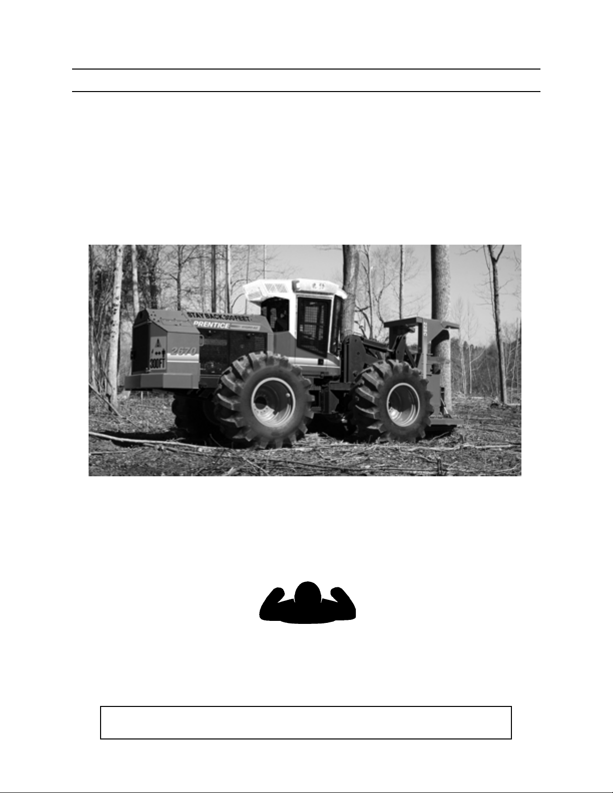
2670 Tractor
To safely operate this machine, follow the instructions in this operator’s manual. Directions in this manual
are referenced from the operator’s seat facing forward (see diagram below).
FORWARD
LEFT RIGHT
BACK
You can help improve this manual. If you find any mistakes, or if you know of a way to improve
procedures, please let us know. Mail your suggestions or comments to the attention of Technical
Publications, Blount, Inc., 3249 South County Road 45, PO Box 568, Owatonna, MN 55060-0568.
This operator’s manual includes information available and current at the time of approval for printing.
Blount, Inc., reserves the right to improve its product without giving prior notice or incurring obligation.
2570/2670 0806
iii
Page 4
TO THE OPERATOR
SAFETY SYMBOLS
SAFETY ALERT SYMBOL
The Safety Alert Symbol means
ATTENTION!
BE ALERT!
YOUR SAFETY IS INVOLVED!
G.033.02
This safety symbol is used to convey important safety messages.
To avoid personal injury and/or property damage, when you see
this symbol, follow the corresponding safety message.
Understand signal words: DANGER, WARNING, and
CAUTION are used with the SAFETY ALERT SYMBOL.
DANGER IDENTIFIES A HAZARD OR UNSAFE
PRACTICE THAT WILL RESULT IN SEVERE
PERSONAL INJURY OR DEATH.
WARNING identifies a hazard or unsafe practice
that could result in severe personal injury or
death.
CAUTION identifies a hazard or unsafe practice
that could result in personal injury or property
damage.
2570/2670
NOTICE identifies important installation, operation,
or maintenance information.
iv
0806
Page 5

TO THE OPERATOR
CONTENTS
PRODUCT PROTECTION PLAN ......................... i
Tractor ........................................................... i
Attachment .....................................................ii
00 - TO THE OPERATOR .................................... iii
Safety Symbols .............................................. iv
01 - GENERAL SAFETY ................................... 1-1
Safety Alert Symbol .................................... 1-1
Operator Preparation .................................. 1-1
Attachment Danger Area ............................ 1-1
Battery Safety ............................................. 1-2
Cooling Fan ................................................ 1-2
Discharge Accumulator ............................... 1-3
Drive w/Care ............................................... 1-3
Electric Lines .............................................. 1-4
Fire Prevention/First Aid ............................. 1-5
Fluids Under Pressure ................................ 1-5
Hand Holds & Steps ................................... 1-6
Hand Signals .............................................. 1-6
Hoses & Fittings ......................................... 1-7
Lift Arm Safety ............................................ 1-8
No Riders on Machine ................................ 1-8
Operator Safety .......................................... 1-9
Practice Safe Maintenance ......................... 1-9
Pressure Settings ..................................... 1-10
Protective Clothing ................................... 1-10
Protective devices/Equipment .................. 1-10
Radiator Cap ............................................ 1-11
Refueling .................................................. 1-11
ROPS/FOPS/OPS Cab Structure ............. 1-11
Seat Belt ................................................... 1-12
Servicing Control Valves ........................... 1-12
Servicing Machine w/Engine Running ...... 1-12
Slope Operation ........................................ 1-13
Starter Circuitry ......................................... 1-13
Tire Safety ................................................ 1-14
Unauthorized Welding .............................. 1-14
Use Articulation (Frame) Lock .................. 1-15
02 - SAFETY DECALS ...................................... 2-1
Tractor Exterior ........................................... 2-1
Tractor Interior ............................................ 2-2
SS56 Bunching Saw ................................... 2-3
SH56 Bunching Saw ................................... 2-4
RH54 Shear ................................................ 2-5
SC56 Bunching Saw ................................... 2-6
03 - COMPONENT TERMINOLOGY ................ 3-1
Tractor ....................................................... 3-1
SS56 Bunching Saw ................................... 3-2
03 - COMPONENT TERMINOLOGY (CONT.)
SH56 Bunching Saw ................................... 3-3
RH54 Shear ................................................ 3-4
SC56 Bunching Saw ................................... 3-5
04 - CONTROLS AND INSTRUMENTS............ 4-1
Operator’s Station (Steering Wheel) ........... 4-1
Operator’s Station (Joystick Wheel) ........... 4-2
Instrument Panel ........................................ 4-3
Right Console ............................................. 4-4
Joystick Control RH .................................... 4-5
Bunching Arm Switch .................................. 4-6
Joystick Control LH (optional) ..................... 4-7
Propel Pedals ............................................. 4-8
Saw/Shear Gathering Arm Pedals .............. 4-8
Brake Pedals ............................................ 4-10
Throttle ..................................................... 4-11
Transmission Shift Control........................ 4-12
Steering Column ....................................... 4-13
Seat Belt ................................................... 4-13
Operator’s Seat ........................................ 4-14
Axle Differential Lock ................................ 4-16
Air Filter Warning Indicator ....................... 4-17
Main Hydraulic Filter Warning Indicator .... 4-17
Saw Hydraulic Filter Warning Indicator..... 4-18
Charge Hydraulic Filter Warning Indicator 4-18
Low Fuel Warning Indicator ...................... 4-18
Fuel Tank Sight Gauges ........................... 4-19
Engine Oil Pressure Gauge ...................... 4-19
Water Temperature Gauge ....................... 4-20
Low Hydraulic Oil Warning Indicator......... 4-20
Engine Maintenance Warning Indicator .... 4-20
Wait to Start Warning Indicator ................. 4-21
Engine Warning Indicator ......................... 4-21
Engine Stop Warning Indicator ................. 4-22
Saw Tachometer ....................................... 4-22
Hydraulic Oil Reservoir Sight Gauges ...... 4-23
Hydraulic Oil Temperature Gauge ............ 4-23
MDDM ............................................... 4-24–29
Sidecut Switch .......................................... 4-30
Engine Start-Attachment On/Off Switch ... 4-31
Ignition Switch .......................................... 4-31
Hourmeter ................................................. 4-32
Horn Switch .............................................. 4-32
Override Switch ........................................ 4-32
Lights ..................................................... 4-33
Air Conditioning/Heater Controls .............. 4-34
Cab Heater Temperature Control .............. 4-35
Auto-shift Switch ....................................... 4-36
Power Outlets ........................................... 4-36
2570/2670 0806
v
Page 6

CONTENTS
TO THE OPERATOR
04 - CONTROLS AND INSTRUMENTS (CONT.)
Circuit Breakers ........................................ 4-37
Master Battery Disconnect Switch ............ 4-38
Sliding Window ......................................... 4-38
Emergency Window Exit ........................... 4-38
Shut-off Manifold Valve ............................. 4-39
Articulation Lock ....................................... 4-40
Cab Tilt Control ......................................... 4-41
Hydraulic Diagnostic Center ..................... 4-41
AM/FM Stereo Cassette Radio ................. 4-42
05 - PRE-START INSPECTION ........................ 5-1
Pre-start Checks: On the Ground ............... 5-1
Pre-start Checks: In the Cab ...................... 5-2
Fire Prevention ........................................... 5-3
06 - OPERATION .............................................. 6-1
General Guidelines ..................................... 6-1
Operator Preparation .................................. 6-1
Getting on Machine .................................... 6-2
Handholds & Steps ..................................... 6-2
Seat Belt ..................................................... 6-2
Starting the Engine ................................. 6-3–4
Cold Weather Starting ................................ 6-5
Jump-starting Battery ................................. 6-6
Warm-up Period.......................................... 6-7
Slope Operation .......................................... 6-8
Operating the Hydrostatic Transmission..... 6-9
Prepare for Operation ................................. 6-9
Driving the Tractor .................................... 6-10
Stopping the Tractor ................................. 6-11
Service Stopping ...................................... 6-11
Stopping the Engine/Parking Machine ..... 6-12
Getting Off Machine .................................. 6-13
Operating the SS56 & SH56 Saws
(Single Cut) ........................................ 6-14
Saw Operation Danger Area .............. 6-14
Dangerous Operation Practices ......... 6-15
Operation in Rocky Terrain ................. 6-15
Bunching Saw Start Up ...................... 6-16
Bunching Saw Operation ................... 6-16
Single Tree Felling ............................. 6-17
Safety Instructions .............................. 6-18
Releasing Trees ................................. 6-19
Felling & Bunching ............................. 6-20
Operating the SH56 Saw
(Double Cut) ....................................... 6-21
Saw Operation Danger Area .............. 6-22
Dangerous Operation Practices ......... 6-23
Operation in Rocky Terrain ................. 6-23
Bunching Saw Start Up ...................... 6-24
Bunching Saw Operation ................... 6-24
06 - OPERATION (CONT.)
Operating the SS56 Bunching Saw
(Double Cut) ....................................... 6-27
Saw Operation Danger Area .............. 6-27
Dangerous Operation Practices ......... 6-28
Operation in Rocky Terrain ................. 6-28
Bunching Saw Start Up ...................... 6-29
Bunching Saw Operation ................... 6-30
Operating the RH54 Shear ....................... 6-32
Shear Operation Danger Area............ 6-32
Safety Instructions .............................. 6-32
Shear Operation ................................. 6-33
Releasing Trees ................................. 6-35
Felling & Bunching ............................. 6-36
Operating the SC56 Bunching Saw
(Single Cut) ........................................ 6-38
Saw Operation Danger Area .............. 6-38
Dangerous Operation Practices ......... 6-39
Operation in Rocky Terrain ................. 6-39
Bunching Saw Start Up ...................... 6-40
Bunching Saw Operation ................... 6-40
Single Tree Felling ............................. 6-41
Safety Instructions .............................. 6-42
Releasing Trees ................................. 6-43
Operating the SC56 Bunching Saw
(Double Cut) ....................................... 6-46
Saw Operation Danger Area .............. 6-46
Dangerous Operation Practices ......... 6-47
Operation in Rocky Terrain ................. 6-47
Bunching Saw Start Up ...................... 6-48
Bunching Saw Operation ................... 6-48
Tilting the Cab........................................... 6-52
Lowering the Cab .................................. 6-53
Using the Pressurized Water System ....... 6-55
Using the Override Switch ........................ 6-55
BREAK-IN PERIOD .......................................... 7-1
Tractor ....................................................... 7-1
Attachment Break-in ................................... 7-2
TRANSPORTING.............................................. 8-1
Loading Instructions ................................... 8-1
FUELS AND LUBRICANTS .............................. 9-1
Fuel ....................................................... 9-1
Engine Oil (Cummins) ................................ 9-2
Hydraulic Oil ............................................... 9-3
Transfer Case Lubrication Fluid.................. 9-3
Axle Fluids .................................................. 9-4
Grease ....................................................... 9-4
Cab Hand Pump Fluid ................................ 9-5
Brake Fluid ................................................. 9-5
Storing Lubricants ....................................... 9-6
2570/2670
vi
0806
Page 7

TO THE OPERATOR
MAINTENANCE SAFETY ............................... 10-1
Before Maintenance ................................. 10-1
Practice Safe Maintenance ....................... 10-1
Accumulator .............................................. 10-2
Hydraulic Safety ....................................... 10-2
Lift Arm Safety .......................................... 10-3
Protective Clothing ................................... 10-3
Servicing Control Valves, Cylinders,
Pumps & Motors ................................. 10-3
Unauthorized Welding .............................. 10-3
During Maintenance ................................. 10-4
Battery Safety ........................................... 10-4
Cooling Fan .............................................. 10-4
Diesel Exhaust .......................................... 10-5
Fuels & Lubes ........................................... 10-5
Fluids Under Pressure .............................. 10-5
Pinch Points .............................................. 10-5
Servicing Tractor w/Engine Running ........ 10-6
Checking Hydraulic Pressure ................... 10-6
Tire Safety ................................................ 10-6
Use Articulation (Frame Lock) .................. 10-7
Installing Articulation Lock ........................ 10-7
Removing Articulation Lock ...................... 10-7
Using Saw Tooth Guard ............................ 10-8
After Maintenance .................................... 10-9
Disposing of Waste ................................... 10-9
Storing Flammable Fluids ......................... 10-9
SCHEDULED/PERIODIC MAINTENANCE
SERVICES ...................................................... 11-1
Lubrication and Maintenance Intervals ..... 11-1
Lubrication Notice ..................................... 11-1
Position Machine for Maintenance ........... 11-1
As Required .............................................. 11-2
Check Electrical System .................... 11-9
Check/Replace Polycarbonate Front ........
Window & Skylight ..................... 11-12
Clean Windshield & Windows .......... 11-12
Clean & Replace Cab Filters ............ 11-13
Clean Fuel Tank Strainer .................. 11-14
Check Oil Hoses & Fittings .............. 11-14
Bleed Brakes .................................... 11-15
Accumulator ..................................... 11-16
Clean A/C Condenser ...................... 11-17
Drain & Replace Hydraulic Oil .......... 11-17
Daily or Every 10 Hours ............................ 11-3
Daily Visual Inspection ..................... 11-18
Check Parking Brake ....................... 11-18
Air Cleaner Maintenance .................. 11-19
Check Engine Crank Case Oil ......... 11-22
Check Radiator Coolant Level ......... 11-23
SCHEDULED/PERIODIC MAINTENANCE
SERVICES (CONT.)
Lube Steering Cylinder Base Ends .. 11-24
Lube Rear Axle Front Trunnion ........ 11-24
Lube Rear Axle Rear Trunnion ......... 11-24
Lube Center Pin Bushings ............... 11-24
Lube Lift Cylinder Clevis Pins .......... 11-25
Lube Lift Arm Upper Bushings ......... 11-26
Lube Lift Arm Lower Bushings ......... 11-26
Lube Tilt Cylinder Base Ends ........... 11-26
Lube Tilt Cylinder Base Ends ........... 11-26
Lube Tilt Cylinder Road Ends........... 11-26
Lube Tilt Cylinder Rod Pins .............. 11-27
Lube Tilt Link Bushings .................... 11-27
Lube Notice ...................................... 11-27
Clean Belly Pans, Engine Compartment &
Side Screens ............................. 11-27
Drain Fuel Water Separator ............. 11-29
Inspect Belts..................................... 11-30
Inspect Cooling Fan ......................... 11-30
Check Fire Extinguisher Charge ...... 11-30
Inspect Pressurized Water System .. 11-30
Inspect Seat Belt .............................. 11-32
Weekly or Every 50 Hours ........................ 11-5
Perform Weekly Inspection .............. 11-33
Lube U-Joint, Front Drive Shaft........ 11-34
Lube Pillow Block ............................. 11-34
Lube Slip Joint, Front Drive Shaft .... 11-34
Lube U-Joint, Middle Drive Shaft ..... 11-34
Lube Slip Joint, Middle Drive Shaft .. 11-35
Lube U-Joint, Middle Drive Shaft ..... 11-35
Lube U-Joint, Rear Drive Shaft ........ 11-35
Lube Slip Joint, Rear Drive Shaft ..... 11-35
Lube U-Joint, Rear Drive Shaft ........ 11-36
Lube Steering Shaft Bearing ............ 11-36
Check Hydraulic Fluid Level ............. 11-36
Tighten Axle Mounting Hardware ..... 11-38
Tighten Wheel Lug Bolts .................. 11-38
Lube Axle Bearings .......................... 11-38
Clean Radiator, Oil Cooler & CAC ... 11-39
Check Interlock System ................... 11-39
Check Tire Pressure......................... 11-41
Monthly or Every 250 Hours ..................... 11-6
Drain & Replace Engine Oil & Filter 11-42
Replace Hydrostatic Pressure Filter . 11-43
Check Pump Drive Fluid Level ......... 11-44
Check 2-Speed Trans Fluid Level .... 11-44
Check Differential Fluid Level .......... 11-45
Battery Service ................................. 11-45
Check Service Brake Fluid Level ..... 11-48
Inspect Air Intake & Exhaust System 11-48
2570/2670 0806
vii
Page 8

TO THE OPERATOR
SCHEDULED/PERIODIC MAINTENANCE
SERVICES (CONT.)
Inspect & Lube Seat ......................... 11-49
Check & Adjust Tension of A/C..................
Compressor Belt ........................ 11-49
Check & Torque Trunnion Mounting
Bolts ........................................... 11-50
Every 500 Hours ....................................... 11-7
Replace Hydraulic Return Line Filter 11-51
Check Radiator & Add Conditioner .. 11-52
Replace Fuel Lift Pump Pre-Filter .... 11-53
Replace Primary Fuel Filter .............. 11-53
Bleed the Fuel System ..................... 11-54
Replace Pilot Pressure Filter ............ 11-55
Replace Coolant Filter ...................... 11-56
Replace Inline Load Sense Filter ..... 11-57
Every 1000 Hours ..................................... 11-8
Tighten Motor Mounts ...................... 11-58
Tighten Transmission Mounts .......... 11-58
Lube Cab Door Hinges..................... 11-58
Drain & Fill Transmission ................. 11-59
Drain & Fill Pump Drive .................... 11-60
Change Hydraulic Reservoir Fluid ... 11-61
Drain & Fill Differential ..................... 11-62
Flush & Fill Cooling System ............. 11-63
Replace Hydraulic Tank Breather ..... 11-64
Seat Maintenance ............................ 11-64
Inspect Drive Belt & Tension ............ 11-64
PERIODIC MAINTENANCE ATTACHMENTS 12-1
SS56 Bunching Saw Chart ....................... 12-1
Every 4 Hours ........................................ 12-3
Inspect Saw Teeth ................................. 12-3
Lube Bunching Arm Pin ......................... 12-4
Lube Bunching Arm Bushing ................. 12-4
Lube Bunching Arm Cylinder Road End 12-4
Lube Bunching Arm Cylinder Base End 12-4
Lube Gathering Arm Upper Bunching ... 12-5
Lube Gathering Arm Cylinder Road End 12-5
Lube Gathering Arm Cylinder Base End 12-5
Lube Gathering Arm Lower Bunching ... 12-5
Lube Swing Up Guard ........................... 12-5
Lube Swing Up Cylinder Base End ....... 12-6
Lube Swing Up Cylinder Rod End ......... 12-6
Every 50 Hours ...................................... 12-7
Check Saw Tooth Cap Screw Torque .... 12-7
Every 100 Hours .................................... 12-7
Check Saw Disc to Saw Shaft Cap
Screw Torque ............................... 12-7
Every 250 Hours .................................... 12-8
Check Saw Skid Plate Cap
Screw Torque ............................... 12-8
PERIODIC MAINTENANCE ATTACHMENTS
(CONT.)
Check Saw Motor Housing to
Saw Base Cap Screw Torque ...... 12-8
Check Saw Motor to Saw Motor
Housing Cap Screw Torque ......... 12-8
Check Gathering Arm Upper Retaining
Cap Screw Torque ....................... 12-9
Check Saw Disc End Play ..................... 12-9
Every 500 Hours .................................. 12-10
Replace Saw Motor Filters .................. 12-10
As Required ......................................... 12-11
Replace Saw Teeth ............................. 12-11
Adjust Tachometer Sensor .................. 12-12
Saw Tooth Rotation/Replacement
Guidelines .................................. 12-13
SH56 Bunching Saw Chart ..................... 12-14
Every 4 Hours ...................................... 12-16
Inspect Saw Teeth ............................... 12-16
Saw Shaft Bearings ............................. 12-16
Lube Bunching Arm Pin ....................... 12-17
Lube Bunching Arm Bushing ............... 12-17
Lube Bunching Arm Cylinder Rod End 12-17
Lube Bunching Arm Cylinder Base End12-17
Lube Gathering Arm Upper Bunching . 12-18
Lube Gathering Arm Cyl Rod End ....... 12-18
Lube Gathering Arm Cyl Base End ..... 12-18
Lube Gathering Arm Lower Bunching . 12-18
Every 50 Hours .................................... 12-19
Check Saw Tooth Cap Screw Torque .. 12-19
Every 100 Hours .................................. 12-19
Check Saw Disc to Saw Shaft Cap
Screw Torque ............................. 12-19
Every 250 Hours .................................. 12-20
Check Saw Skid Plate Cap
Screw Torque ............................. 12-20
Check Saw Motor Housing to
Saw Base Cap Screw Torque .... 12-20
Check Saw Motor to Saw Motor
Housing Cap Screw Torque ....... 12-20
Check Saw Disc End Play ................... 12-21
Every 500 Hours .................................. 12-22
Replace Saw Motor Filters .................. 12-22
As Required ......................................... 12-23
Replace Saw Teeth ............................. 12-23
Adjust Tachometer Sensor .................. 12-24
Saw Tooth Rotation/Replacement
Guidelines .................................. 12-25
RH54 Shear Chart .................................. 12-26
Daily or Every 10 Hours ...................... 12-27
Lube Shear Cylinder Base End ........... 12-27
2570/2670
viii
0806
Page 9

TO THE OPERATOR
PERIODIC MAINTENANCE ATTACHMENTS
(CONT.)
Lube Shear Cylinder Rod End ............. 12-27
Lube Blade Holder Bushings ............... 12-27
Lube Bunching Arm Pivot Pin .............. 12-28
Lube Bunching Arm Paddle Pin........... 12-28
Lube Bunching Arm Cylinder Rod End 12-28
Lube Bunching Arm Cylinder Base End12-28
Lube Gathering Arm Cyl Base End ..... 12-29
Lube Gathering Arm Cyl Rod End ....... 12-29
Lube Gathering Arm Bunching ............ 12-29
Every 50 Hours .................................... 12-30
Check Shear Blade Gap ...................... 12-30
Check Shear Blade Cap Screw Torque 12-31
Check Shear Blade Sharpness ........... 12-31
SC56 Bunching Saw Chart .................... 12-32
Every 4 Hours ...................................... 12-35
Inspect Saw Teeth ............................... 12-35
Saw Shaft Bearings ............................. 12-35
Daily or Every 10 Hours ...................... 12-36
Lube Bunching Arm Equalizer Bar ...... 12-36
Lube Bunching Arm Pin ....................... 12-36
Lube Bunching Arm Bushing ............... 12-36
Lube Bunching Arm Cylinder Rod End 12-36
Lube Bunching Arm Cylinder Base End12-37
Lube Gathering Arm Upper Bunching . 12-37
Lube Gathering Arm Cyl Rod End ....... 12-37
Lube Gathering Arm Cyl Base End ..... 12-37
Lube Gathering Arm Lower Bunching . 12-38
Lube Bunching Arm Equalizer Bar ...... 12-38
Check Tooth Sharpness ...................... 12-38
Check Arm Cylinder Base Bolts .......... 12-39
Check Grapple & Accumulator Arm
Main Pins Tightness .................. 12-39
Check Motor Cover Retaining Cap
Screw Torque ............................. 12-39
Every 50 Hours .................................... 12-40
Check Saw Tooth Cap Screw Torque .. 12-40
Check tooth Holder Retaining
Cap Screw Torque ..................... 12-41
Every 100 Hours .................................. 12-41
Check Saw Disc to Saw Shaft Cap
Screw Torque ............................. 12-41
Every 250 Hours .................................. 12-42
Check Saw Disc End Play ................... 12-42
Every 500 Hours .................................. 12-43
Check Torque on Saw Disc
Components .............................. 12-43
Grease Saw Motor/Shaft ..................... 12-43
Every 2000 Hours ................................ 12-44
Check Torque on Bearing Carrier
Cap Screws ............................... 12-44
PERIODIC MAINTENANCE ATTACHMENTS
(CONT.)
Check Torque on Saw Motor
Cap Screws ............................... 12-44
Check Torque on Saw Motor Port
Adapter Cap Screws .................. 12-45
Saw Motor Cover Cap Screws ............ 12-45
Tree Support Plate Cap Screws .......... 12-45
As Required ......................................... 12-46
Replace Saw Teeth ............................. 12-46
Saw Tooth Rotation/Replacement
Guidelines .................................. 12-48
STORAGE....................................................... 13-1
Preparing Tractor for Storage ................... 13-1
Taking Machine out of Storage ................. 13-2
TROUBLESHOOTING .................................... 14-1
Tractor ..................................................... 14-1
Engine .......................................... 14-1–9
Hydrostatic Transmission .................... 14-10
Hydraulic System ................................ 14-11
Electrical System ................................. 14-11
Saws ................................................... 14-12
Shear ................................................... 14-14
Seat ................................................... 14-14
Contamination of Hydraulic Comp. ......... 14-15
SPECIFICATIONS .......................................... 15-1
Tractor ..................................................... 15-1
Basic Dimensions of Tractor ..................... 15-2
SS56 Bunching Saw ................................. 15-3
SH56 Bunching Saw ................................. 15-4
RH54 Shear .............................................. 15-5
SC56 Bunching Saw ................................. 15-7
Hydraulic Connection Torque Specifications
SAE 37° Flare Connection .................... 15-7
O-Ring Face Seal Connection ............... 15-8
Torque Chart for Fasteners ....................... 15-9
Cylinder Torque Specifications ............... 15-10
SERIAL NUMBERS ........................................ 16-1
MATERIAL SAFETY DATA SHEETS .............. 17-1
2570/2670 0806
ix
Page 10

TO THE OPERATOR
NOTES
2570/2670
x
0806
Page 11
GENERAL SAFETY
GENERAL SAFETY
Do not operate machine without reading and understanding this
operator’s manual.
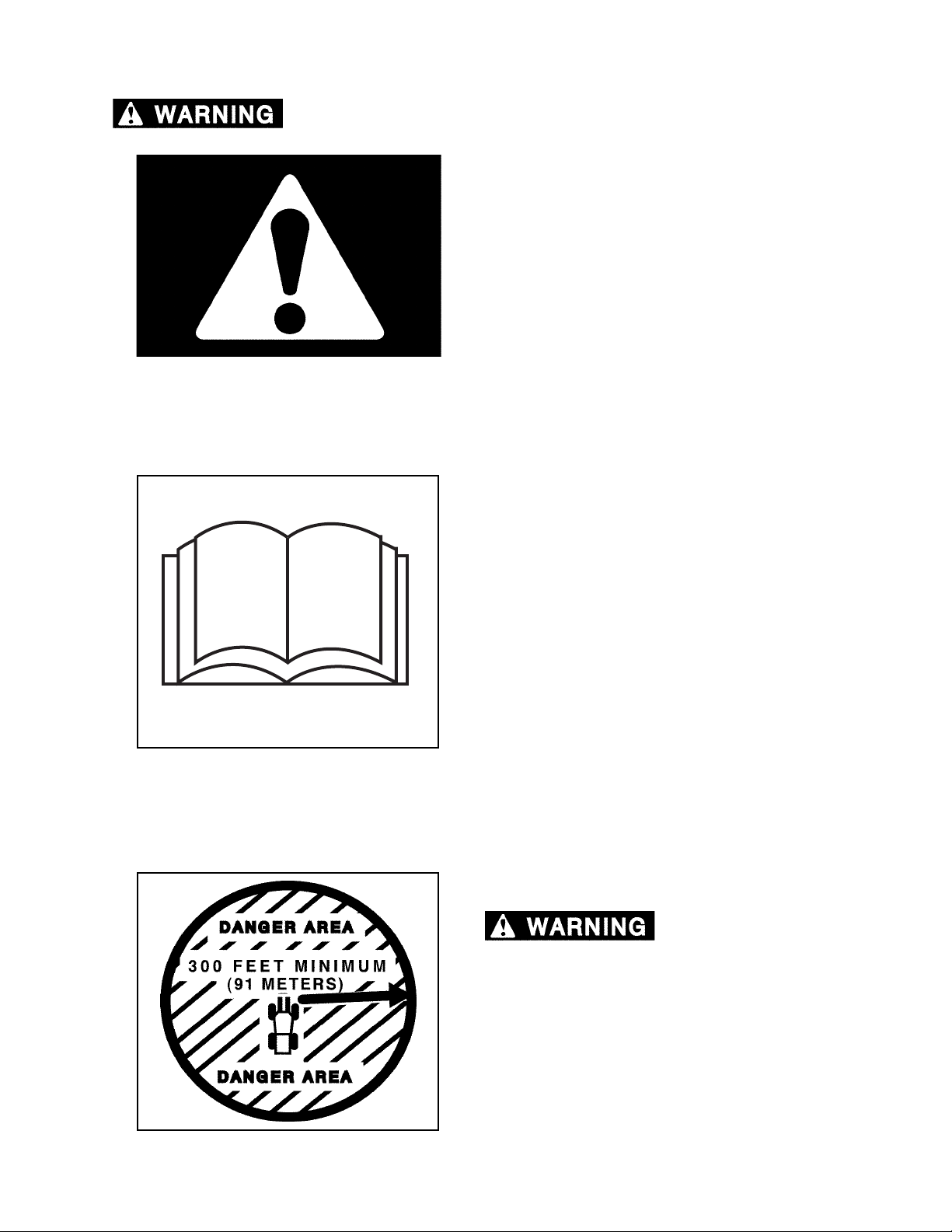
SAFETY ALERT SYMBOL
Read all safety messages.
To avoid personal injury and/or property damage,
follow safety messages.
G.033.02
OPERATOR PREPARATION
G.100.05
Operator must be fully trained, qualified, and
authorized to operate this machine. Before
operating this machine, operator must know the
location and purpose of
• controls
• indicator lights
• instruments
• safety and instruction decals (see Section
2, Safety Decals, in this manual)
ATTACHMENT DANGER AREA
Flying debris, falling
trees, limbs, and tops can cause severe
personal injury or death. Do not operate
attachment within three hundred (300) feet (91
meters) of personnel or machinery.
G.011.02
2570/2670 0906
1-1
Page 12
GENERAL SAFETY
BATTERY SAFETY
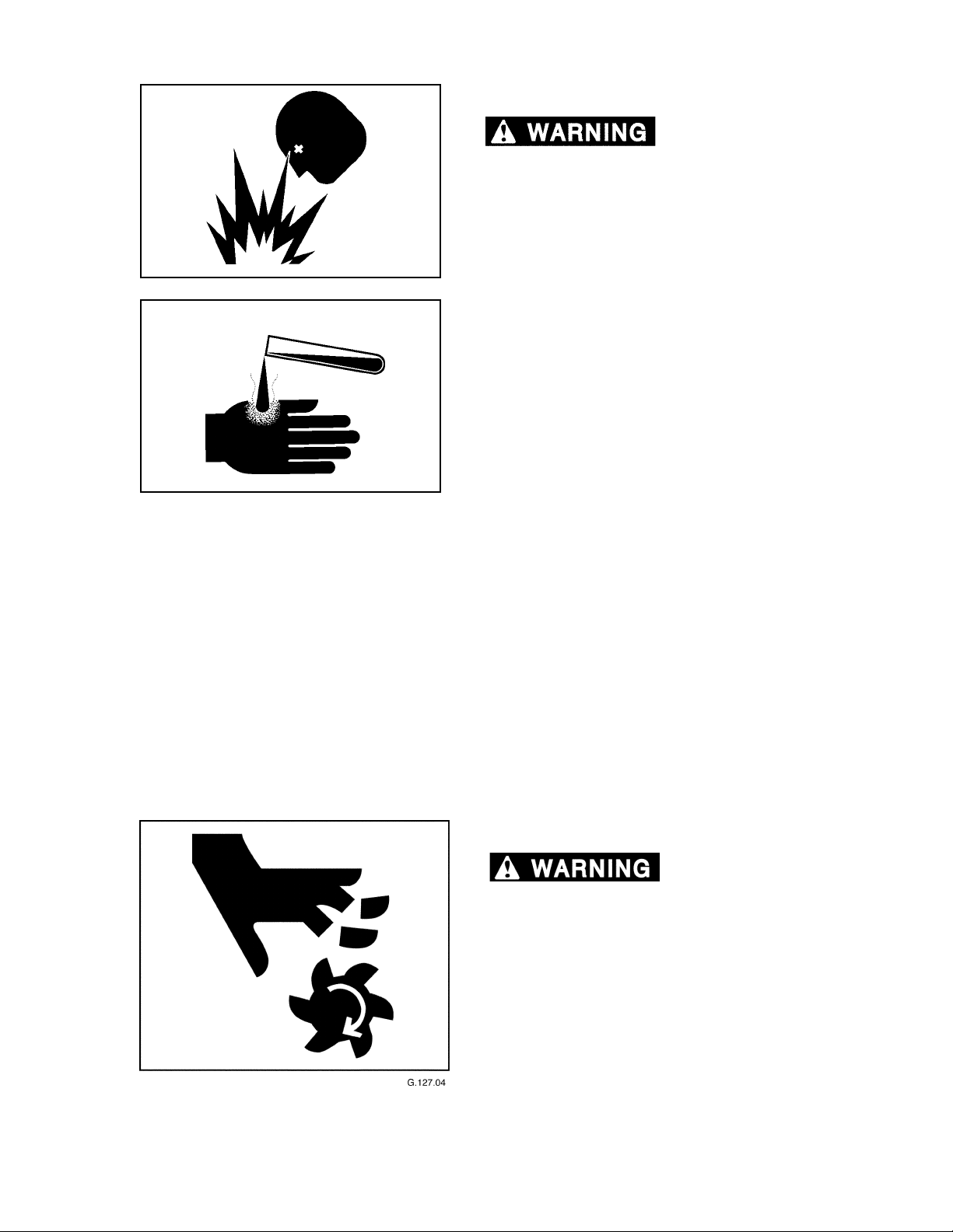
explosive gases.
Keep sparks, flames, and cigarettes away from
batteries. Ventilate properly when charging or
using batteries in enclosed space. Always
shield eyes with goggles and wear a face shield
when working near batteries. Do not lean over
G.019.02
batteries during this operation. Always connect
positive (+) to positive (+) and negative (-) to
negative (-). For further instructions, see Jump
Starting Battery in Section 6, Operation. If
battery acid contacts eyes, flush them with
water for 15 minutes and seek immediate
medical attention.
Battery acid is poisonous and can cause severe
burns. If acid is taken internally, call a
physician immediately. If acid contacts skin or
clothing, flush with water immediately. Keep
G.013.02
batteries away from children.
Battery posts, terminals, and related
accessories contain lead and lead components,
chemicals known to the State of California to
cause cancer and reproductive harm. Wash
hands after handling.
Batteries produce
Never charge a battery or jump start engine if
battery is frozen. Warm battery to 60°F (16°C) or
it may explode. Be sure vent caps are tight.
When jump starting from another machine, be
sure machines do not touch. This machine has
a 12-volt starting system. Use equal voltage for
jump starting.
COOLING FAN
Rotating fan can cause
severe personal injury or death. Cooling fan
can start at any time, even with the motor off.
Keep away from cooling fan at all times.
2570/2670 0906
1-2
Page 13
GENERAL SAFETY
DISCHARGE ACCUMULATOR
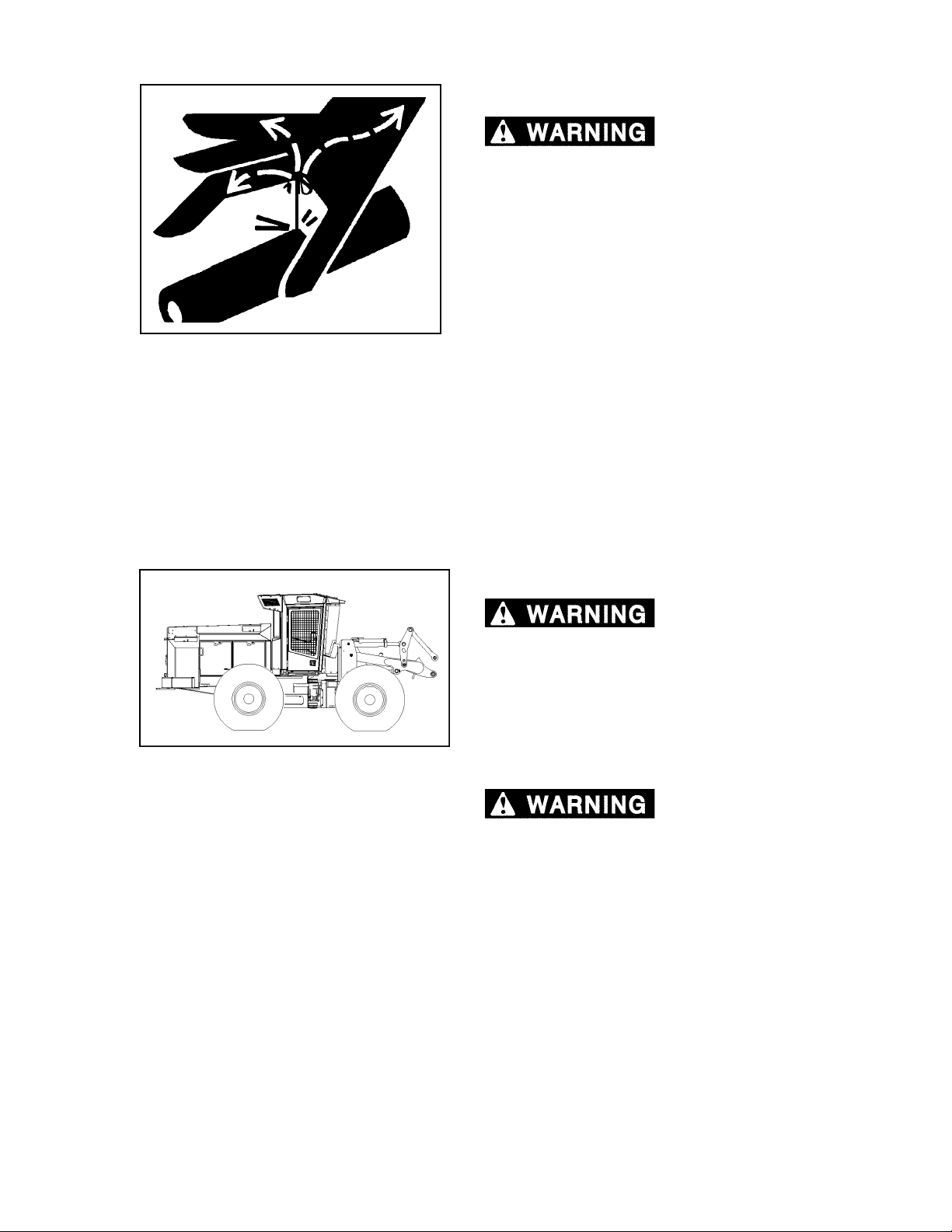
pressure can penetrate skin and cause severe
personal injury or death. Charged accumulator
can cause unexpected movement of functions
with engine off.
DO NOT disconnect hoses or fittings, or attempt to
service the hydraulic accumulator or pilot circuit
without first discharging the accumulator.
If ANY fluid is injected into the skin, seek
medical attention immediately. A serious
G.002.02
infection or reaction can result without proper
medical treatment.
Fluids escaping under
DRIVE WITH CARE
Driving machine
carelessly or too fast for conditions can result
in severe personal injury or death.
ALWAYS wear seat belt, snugly fastened.
DO NOT operate with tires sideways to a slope.
DO NOT speed over rough ground.
DO NOT swiftly turn machine.
Loss of traction can
cause operator to lose control of tractor
resulting in severe personal injury or death.
ALWAYS wear seat belt, snugly fastened.
2570/2670 0906
1-3
Page 14
GENERAL SAFETY
ELECTRIC LINES
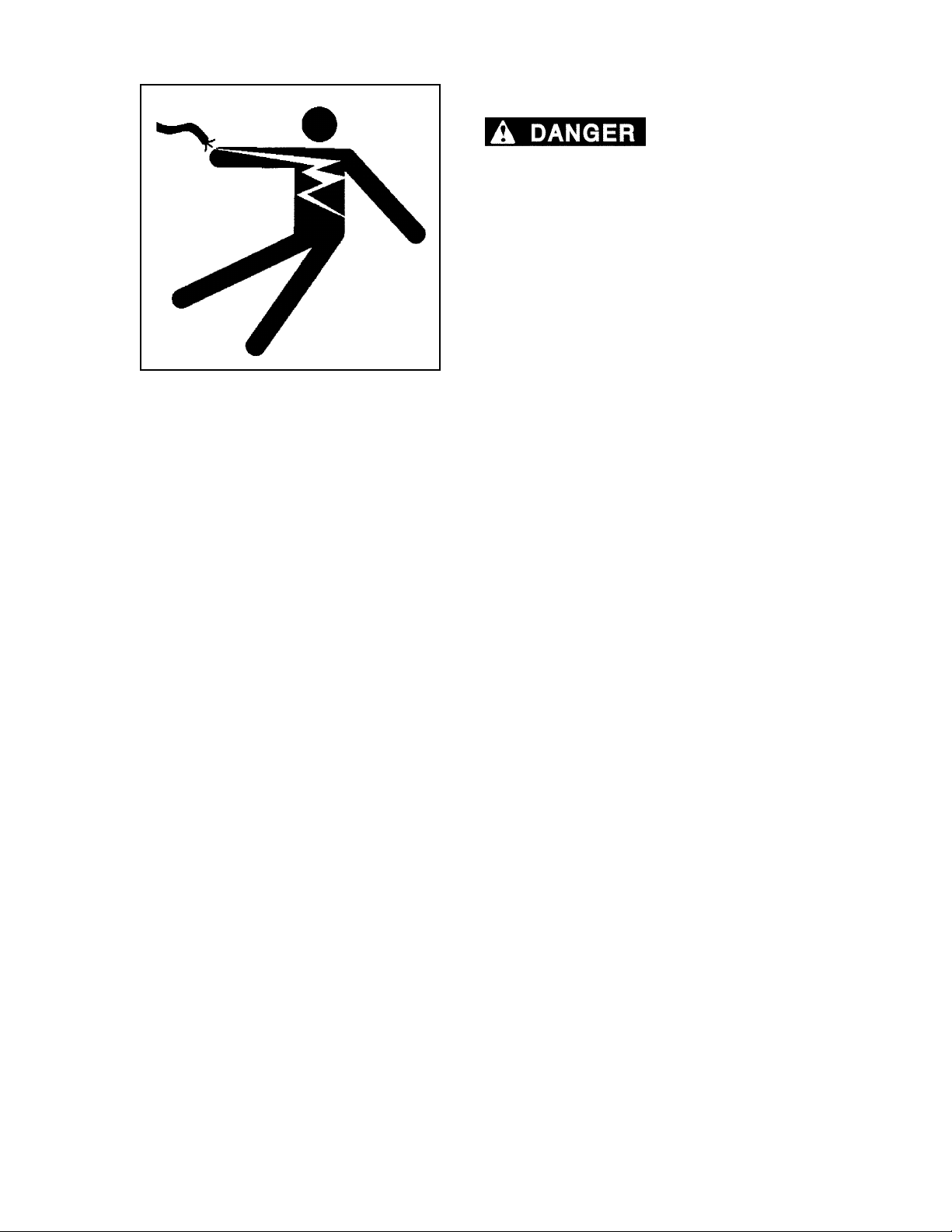
DEATH WILL RESULT FROM CONTACT WITH
ELECTRIC LINES.
Never move any part of machine or load closer
than 10 feet plus twice the line insulator length to
electric lines. A line insulator is what connects an
electric line to an electric pole.
For example, if a line insulator is 6 inches long,
operator must stay at least 10 feet plus twice the
line insulator length (2x6 =12 inches or 1 foot from
electric line, which means you must stay at least
11 feet from the electric line.
G.003.02
If machine touches an electric line, stay inside the
cab. Carefully move machine or load away from
electric line, without pulling the line down.
DO NOT let anyone else touch machine while it is
touching an electric line. If it is not possible to move
the machine away from the electric line without
pulling line down, have someone contact the utility
company to disconnect power from line. If this is
not possible, or if machine begins to burn, jump
away from machine to the ground with both feet
together, in one smooth jump. Do not run or walk
away from machine. Jump with feet together
“bunny hop” away from machine. DO NOT touch
machine and ground at the same time or else
electricity in the line will go through your body. Get
away from machine after jumping.
SERIOUS INJURY OR
Notify the utility company immediately. DO NOT let
anyone near machine while it is touching an
electric line.
2570/2670 0906
1-4
Page 15
GENERAL SAFETY
FIRE PREVENTION/FIRST AID
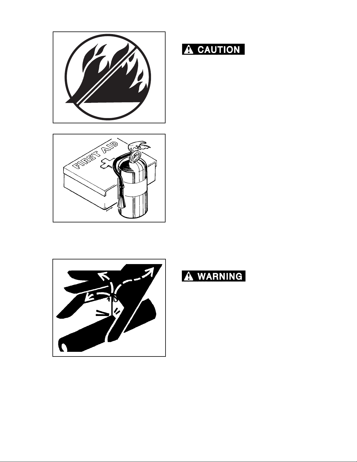
personal injury and/or machine damage.
Keep machine clean. Forest debris, rags, and trash
will cause fires. Remove all debris, rags, and trash
from machine, especially around engine and
hydraulic components.
Repair all hydraulic and fuel leaks immediately. Do
not operate machine with hydraulic or fuel leaks.
Fire prevention beats fire fighting. Remove debris
G.004.05
from all compartments after every eight (8) hours of
operation, or more often, if warranted by working
conditions.
Never use fuel for cleaning purposes.
Do not expose machine to flames, burning brush or
other fire hazards.
At the end of each shift ALWAYS stay with the
machine for at least 30 minutes after shutting down
the engine to ensure there is no forest debris/trash
fire start up. Keep a fire extinguisher ready during
this 30 minute cool down.
Fires can cause
G.005.02
G.002.02
Install a first-aid kit in the cab.
Properly maintain first-aid kit and fully charged fire
extinguisher. Follow instructions provided with
them.
FLUIDS UNDER PRESSURE
Fluids escaping under
pressure can penetrate skin and cause severe
personal injury or death.
Wear eye and personal protection equipment
(PPE)!
Always use a board or cardboard when checking
oil hoses, lines, and fittings periodically for leaks,
cracks or defects. Be sure all clamps are in their
proper position and torqued as required and
specified. Be sure hoses are not twisted or
touching parts.
DO NOT use hands to search for leaks. Escaping
fluids can penetrate skin and enter the
bloodstream. Before disconnecting lines, relieve
all pressure.
DO NOT apply pressure to a damaged line, hose,
or fitting.
If ANY fluid is injected into the skin, seek
medical attention immediately. A serious
infection or reaction can result without proper
medical treatment.
2570/2670 0906
1-5
Page 16
GENERAL SAFETY
HAND HOLD AND STEPS
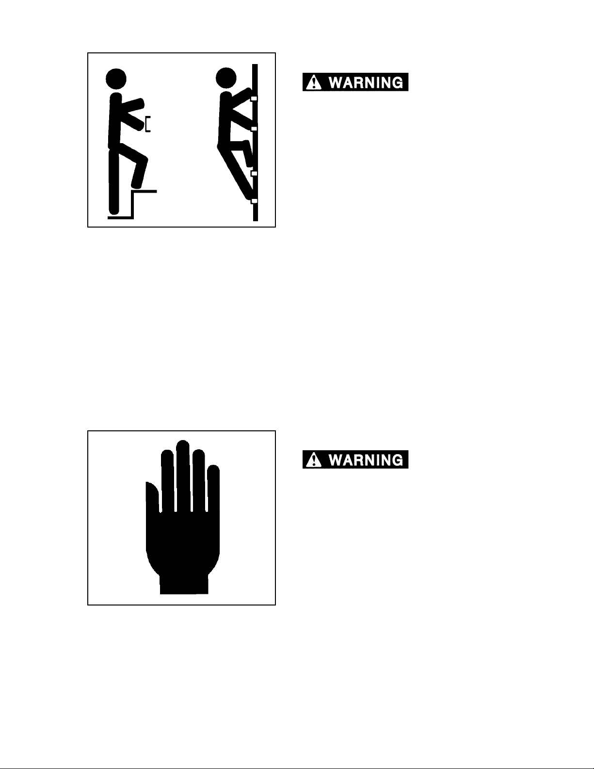
cause severe personal injury or death.
Use provided hand holds and steps while
maintaining at least 3 points of support (1 foot and
2 hands or 2 feet and 1 hand) when getting on and
off machine. Face machine when getting on and
off of it.
Never use controls as hand holds. Never use
steering wheel as a hand hold. Moving the steering
wheel from its center position will COMPLETELY
turn machine right or left.
Slips and falls can
G.006.02
DO NOT mount machine if hand rails or steps are
broken or missing. Get them repaired first.
DO NOT jump on or off machine unless it has
touched a live electrical wire and it must be exited.
Ensure firm foot position when getting on and off
machine. Be careful of slippery conditions on
platform, steps, and hand holds when getting on
and off machine.
Remove oil, grease, mud, ice, etc. before mounting
or dismounting machine.
To prevent slips and falls, replace skid-resistant
material if it is damaged or missing.
HAND SIGNALS
Accidents can cause
severe personal injury or death.
Know and use the hand signals required for
particular jobs.
Know who has the responsibility for signaling.
G.168.05
2570/2670 0906
1-6
Page 17
GENERAL SAFETY
HOSES AND FITTINGS
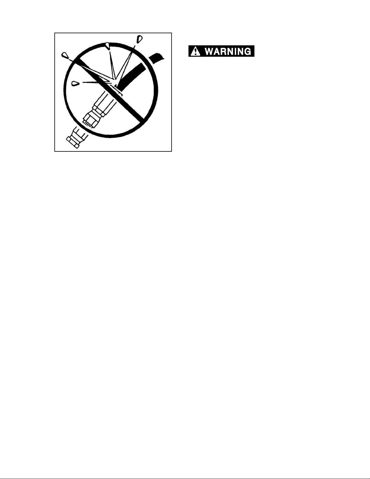
types of hoses and fittings can blow apart and
cause severe personal injury or death.
DO NOT interchange brands or types of hoses
and fittings.
DO NOT install a fitting from one manufacturer on
a hose from a different manufacturer.
DO NOT install crimp fittings on hoses meant for
reusable fittings.
Wear eye and personal protection equipment
(PPE)!
Mismatched brands or
G.007.02
Always use a board or cardboard when checking
oil hoses, lines, and fittings periodically for leaks,
cracks or defects. Be sure all clamps are in their
proper position and torqued as required and
specified. Be sure hoses are not twisted or
touching parts.
2570/2670 0906
1-7
Page 18
DANGER
AREA
GENERAL SAFETY
LIFT ARM SAFETY
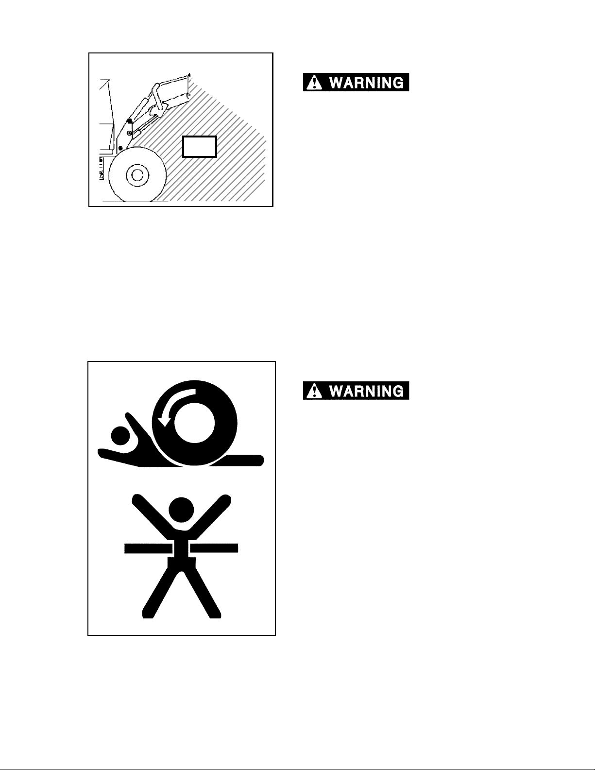
Falling lift arm or
attachment can cause severe personal injury or
death.
DO NOT enter danger area under or around lift arm
when either of the following conditions apply:
• attachment is off the ground
• engine is running
G.008.02
G.009.02
NO RIDERS ON MACHINE
Machine riders can fall
from machine or be injured by movement of
machinery, causing severe personal injury or
death.
Do not allow riders on any machine that is
operating or moving.
2570/2670 0906
1-8
Page 19
GENERAL SAFETY
OPERATOR SAFETY
G.010.02
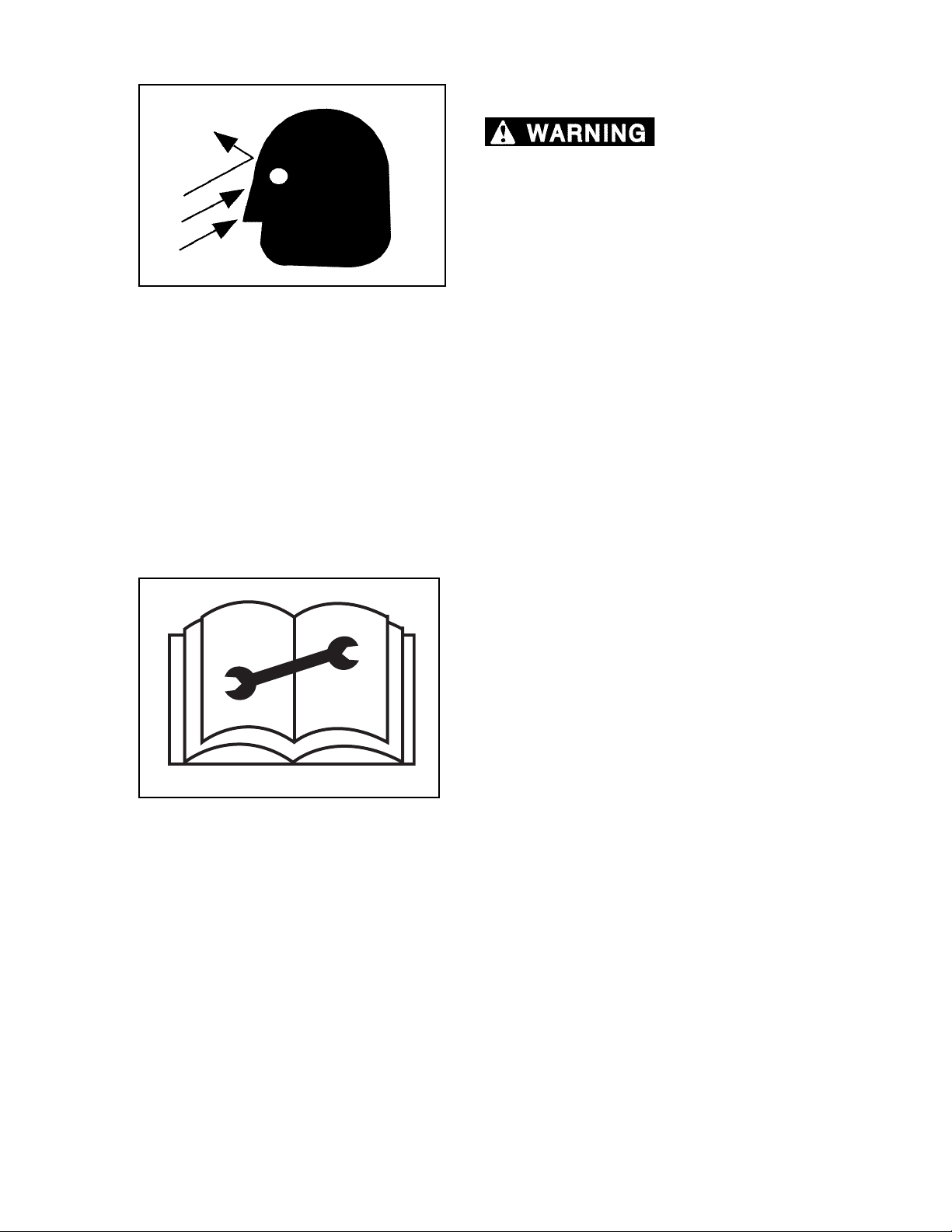
limbs, and/or other material can cause severe
Flying debris, tree
personal injury or death.
When operating machine:
1. Keep cab door closed.
2. Polycarbonate window material and/or cab
guarding MUST be in place.
3. All cab openings (front, side, and rear)
MUST be covered with polycarbonate
window material (no glass) and/or
protective screen.
4. Window guarding MUST be locked
in place.
Polycarbonate windows MUST be replaced if
damaged. For details, refer to Section 11,
Scheduled/Periodic Maintenance Service.
PRACTICE SAFE MAINTENANCE
104.05
Read service and maintenance manuals and
understand service procedures before performing
service/maintenance.
Understand service procedures before performing
maintenance. When performing maintenance, keep
area around machine clean and dry.
DO NOT service machine while it is moving. Keep
away from power-driven parts. Lower attachment to
the ground. Disengage power. Shut engine down.
Move controls in all directions to relieve hydraulic
pressure. Remove key from ignition. Allow machine
to cool down.
Support all raised equipment.
Keep all machine parts in good condition, and be
sure parts are properly installed. Repair damage
immediately. Repair all hydraulic and fuel leaks
immediately. Replace worn or broken parts.
Remove any buildup of grease, oil, or debris.
Disconnect battery ground cable (-) before
repairing the electrical system.
2570/2670 0906
1-9
Page 20
GENERAL SAFETY
PRESSURE SETTINGS
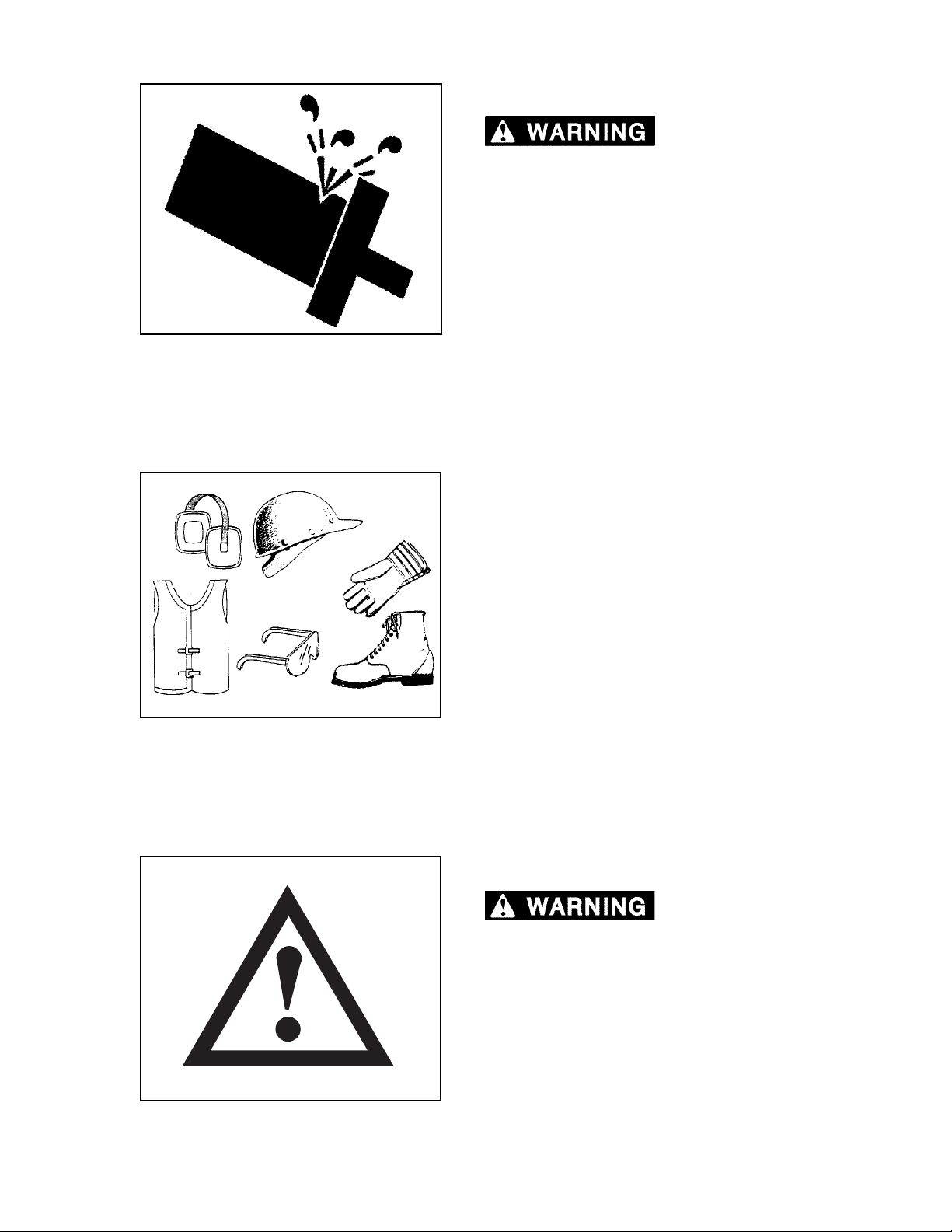
pressure can cause component or structural
failure, which may result in severe personal
injury or death.
DO NOT exceed factory-adjusted pressure
settings.
G.012.02
PROTECTIVE CLOTHING
Excessive hydraulic
G.051.02
Wear OSHA-approved protective clothing when
working on or near this machine, such as
• ear protection • hard hat
• gloves • orange vest
• goggles • steel-toed shoes
Wear snug, protective clothing that is belted where
required.
Remove jewelry before working on or near this
machine.
PROTECTIVE DEVICES/EQUIPMENT
Misuse, interference
and ignorance of protective equipment or
devices can cause severe personal injury or
death.
Alarms, fire prevention equipment, ROPS/FOPS/
OPS, and other safety equipment is installed on
machine for your protection.
Never ignore, disconnect, disable or modify
protection equipment in any manner.
G.051.02
2570/2670 0906
1-10
Page 21
GENERAL SAFETY
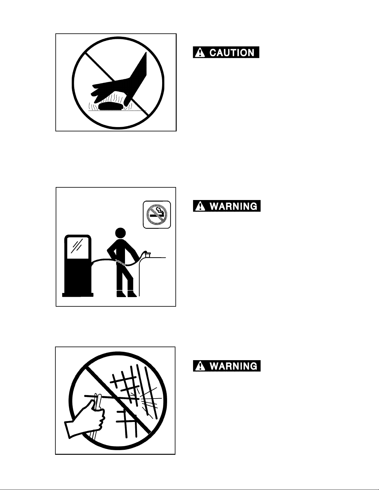
RADIATOR CAP
system can cause scalding burns.
Allow system to cool. Wear gloves. Remove cap
slowly.
G.014.02
REFUELING
Pressurized cooling
G.015.02
Fires and explosions
can cause severe personal injury or death.
Handle fuel with care. It is highly flammable.
DO NOT refuel machine while smoking or when
near open flame or sparks.
Always stop engine before refueling. Fill fuel tank
outdoors. Prevent fires by keeping machine clean
of trash, grease, and debris. Always clean up
spilled fuel.
ROPS/FOPS/OPS CAB STRUCTURE
Altering ROPS/FOPS/
OPS structure can cause severe personal injury
or death.
If ROPS/FOPS/OPS structure is damaged (bent or
cracked), it should be inspected by your Hydro-Ax
dealer or by a factory representative. Replace
ROPS/FOPS/OPS structure if it fails inspection. Do
not alter ROPS/FOPS/OPS structure.
G.016.02
2570/2670 0906
1-11
Page 22
GENERAL SAFETY
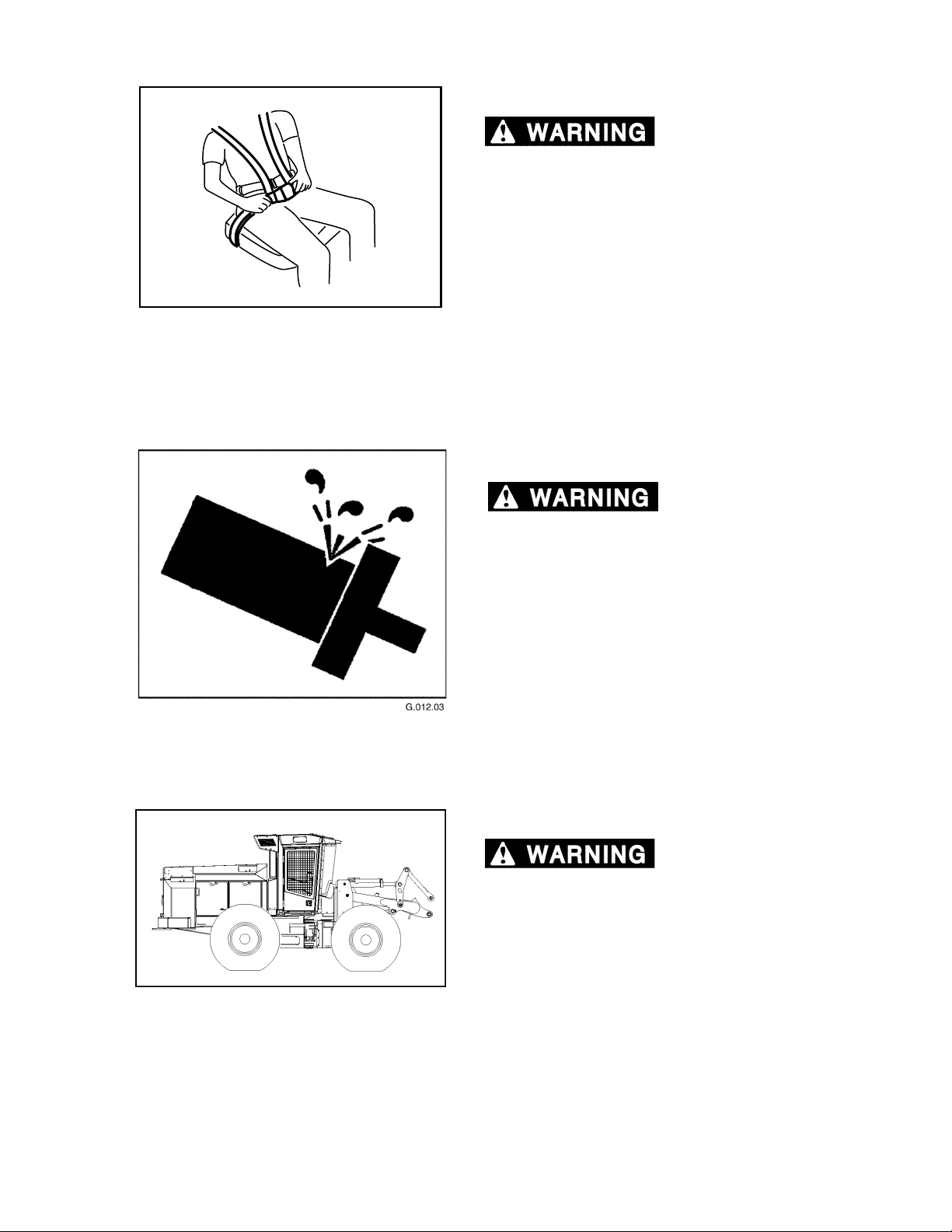
SEAT BELT
stop can cause severe personal injury or death.
To reduce risk of personal injury resulting from a
roll over or sudden stop, always wear a seat belt
fastened snugly when operating machine.
This machine can change directions rapidly. It can
start and stop quickly. See Section 6, Operation, in
this manual for instructions on properly using your
seat belt.
G.017.02
SERVICING CONTROL VALVES
A roll over or sudden
Increasing relief valve
settings could cause machine or component
failure resulting in severe personal injury or
death. Do not switch lines from one valve to
another.
Special tools and training are required to service
control valves, cylinders, pumps and motors. If
these parts need service, see an authorized dealer.
SERVICING MACHINE WITH ENGINE RUNNING
Servicing machine with
engine running can cause severe injury or
death. Shut down engine and relieve hydraulic
pressures before servicing unless procedure
requires engine running. When maintenance
procedure requires engine running, ONLY
qualified service technicians should service
machine.
2570/2670 0906
1-12
Page 23
GENERAL SAFETY
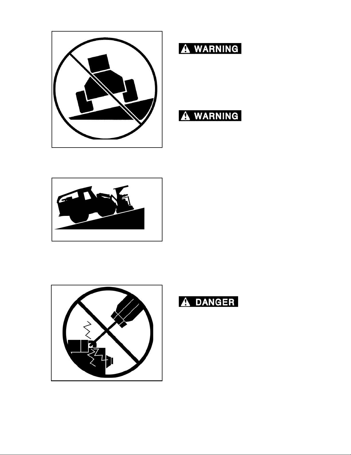
SLOPE OPERATION
slope can cause machine to tip over resulting
in severe personal injury or death.
ALWAYS wear seat belt snugly fastened.
DO NOT operate with tires sideways to a slope.
On all slopes, only operate with machine pointed
up or down the slope.
steep slope can cause operator to lose control
of tractor and roll over, resulting in severe
personal injury or death.
Operation across a
Loss of traction on a
10 feet
G.018.02
3 feet
G.050.02
ALWAYS wear seat belt, snugly fastened.
DO NOT operate machine on slopes exceeding
thirty (30) percent (16.7° angle from horizon). A
thirty percent slope can be visualized by a three (3)
foot rise in a ten (10) foot distance.
STARTER CIRCUITRY
MACHINE WILL START
IN GEAR IF START CIRCUITRY IS BYPASSED.
Do not attempt to start machine engine by shorting
starter circuit across starter terminals. Doing so
may cause unintended machine movement which
could result in severe personal injury or death and
serious machine and/or property damage.
G.0SS.05
2570/2670 0906
1-13
Page 24
GENERAL SAFETY
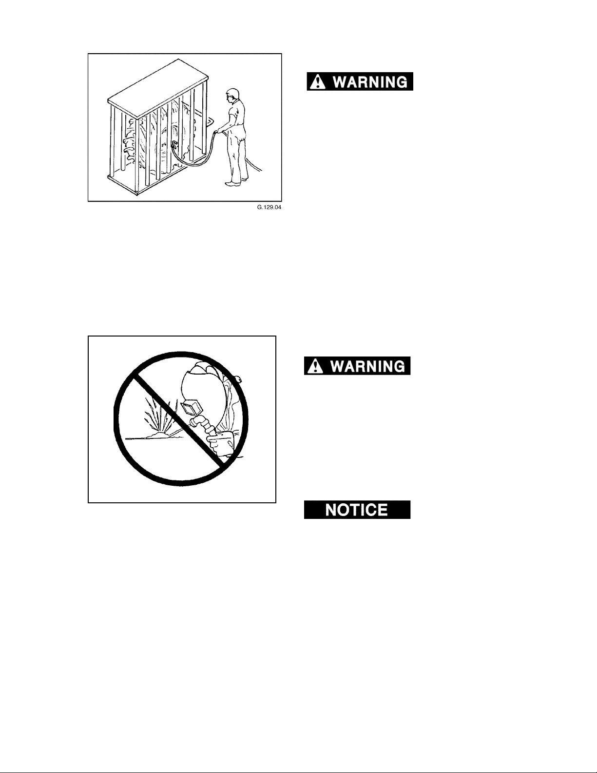
TIRE SAFETY
cause severe personal injury or death. DO NOT
attempt to mount a tire without the proper
equipment and experience to do the job.
Have tires mounted by an authorized dealer or by a
qualified repair service.
Maintain proper tire pressure. DO NOT inflate tires
above recommended pressure.
A tire explosion can
G.020.02
UNAUTHORIZED WELDING
Unauthorized welding
can cause structural failure and/or severe
personal injury or death.
DO NOT weld on any structural member.
Any unauthorized welding or repair will void
the Warranty.
Once authorized, turn battery disconnect switch
OFF and place welding ground (stinger) as close to
the weld site as possible. Do not allow weld current
to pass through bearings, bushings or pivot points.
Welding can cause
damage to the electrical system.
2570/2670 0906
1-14
Page 25
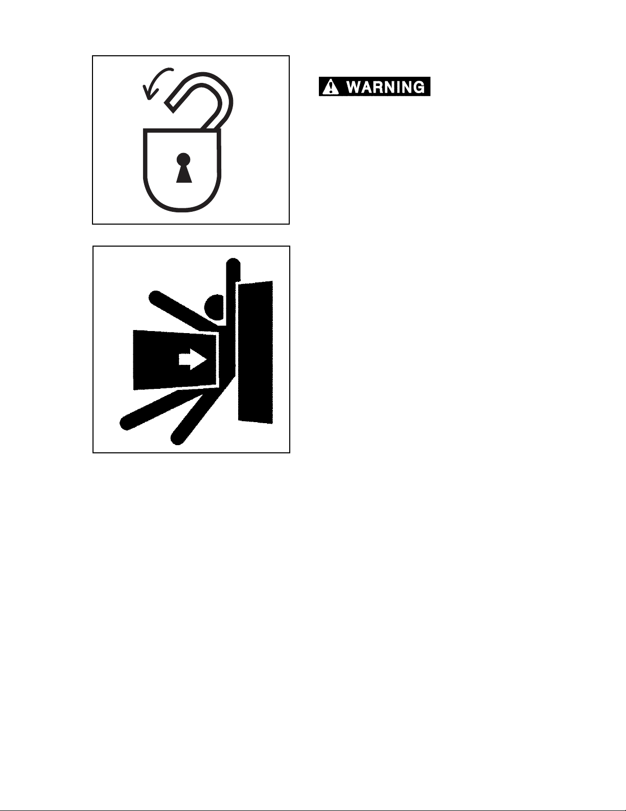
GENERAL SAFETY
USE ARTICULATION (FRAME) LOCK
with a person in center hinge crush point area,
severe personal injury or death could occur.
Moving steering wheel could COMPLETELY turn
machine right or left.
Do not use steering wheel as a handhold when
mounting or dismounting machine.
NEVER stand in this area with engine running.
Install articulation lock BEFORE performing service
101.05
or maintenance.
If steering is activated
G.021.02
2570/2670 0906
1-15
Page 26

GENERAL SAFETY
NOTES
2570/2670 0906
1-16
Page 27
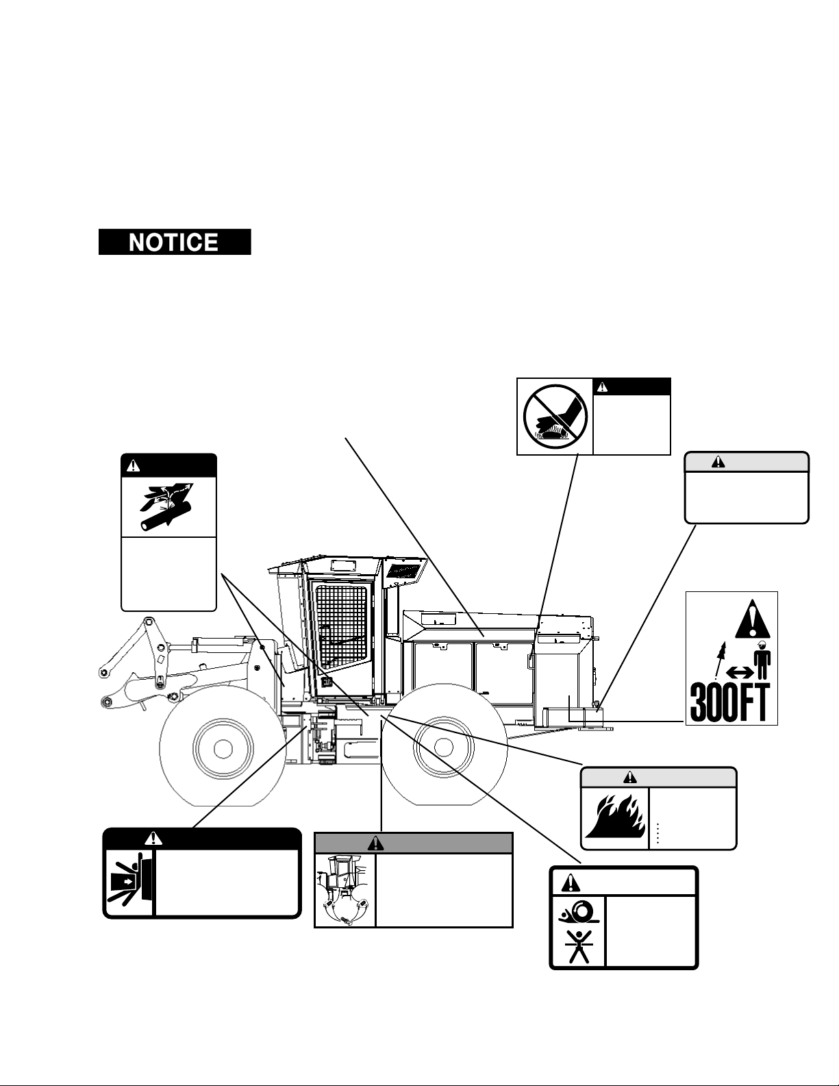
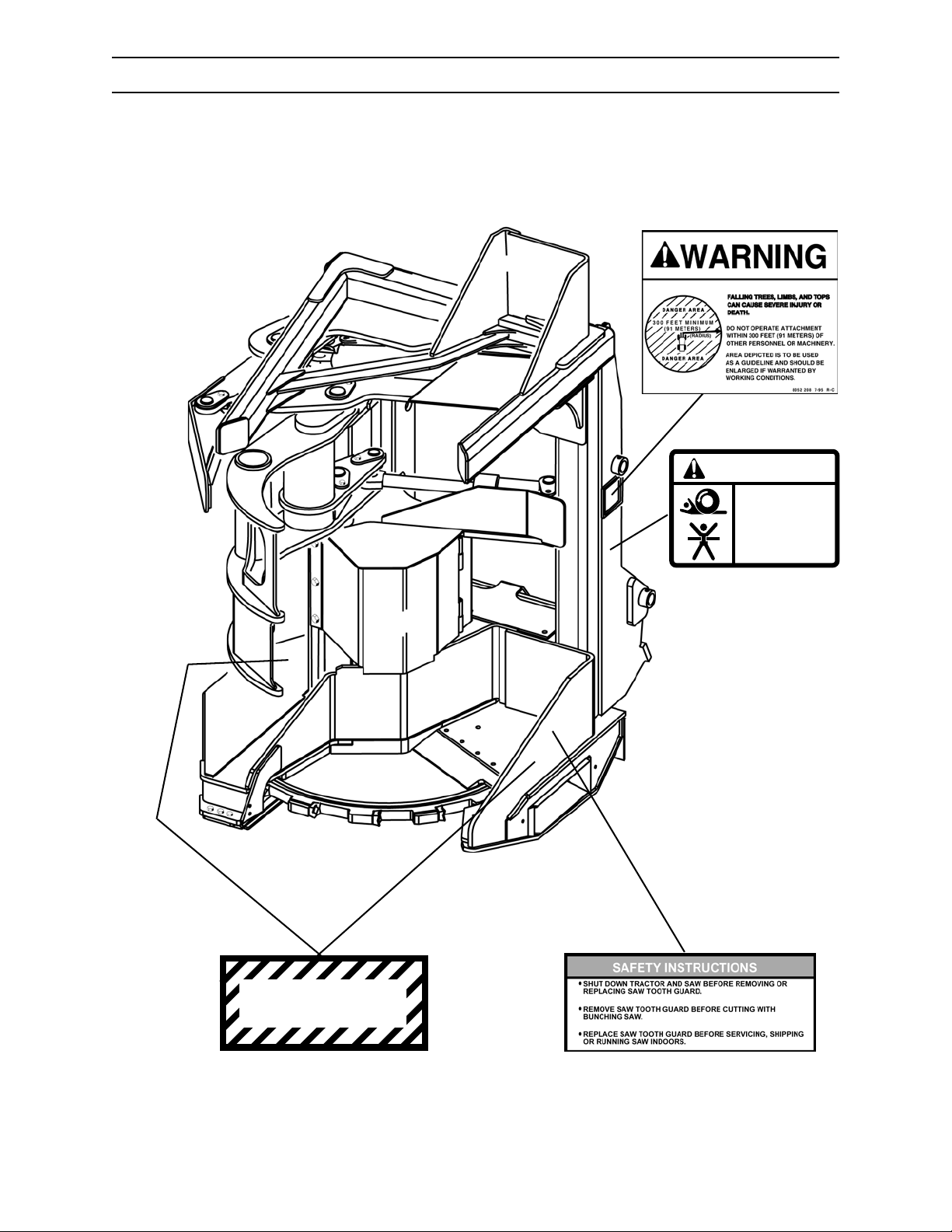
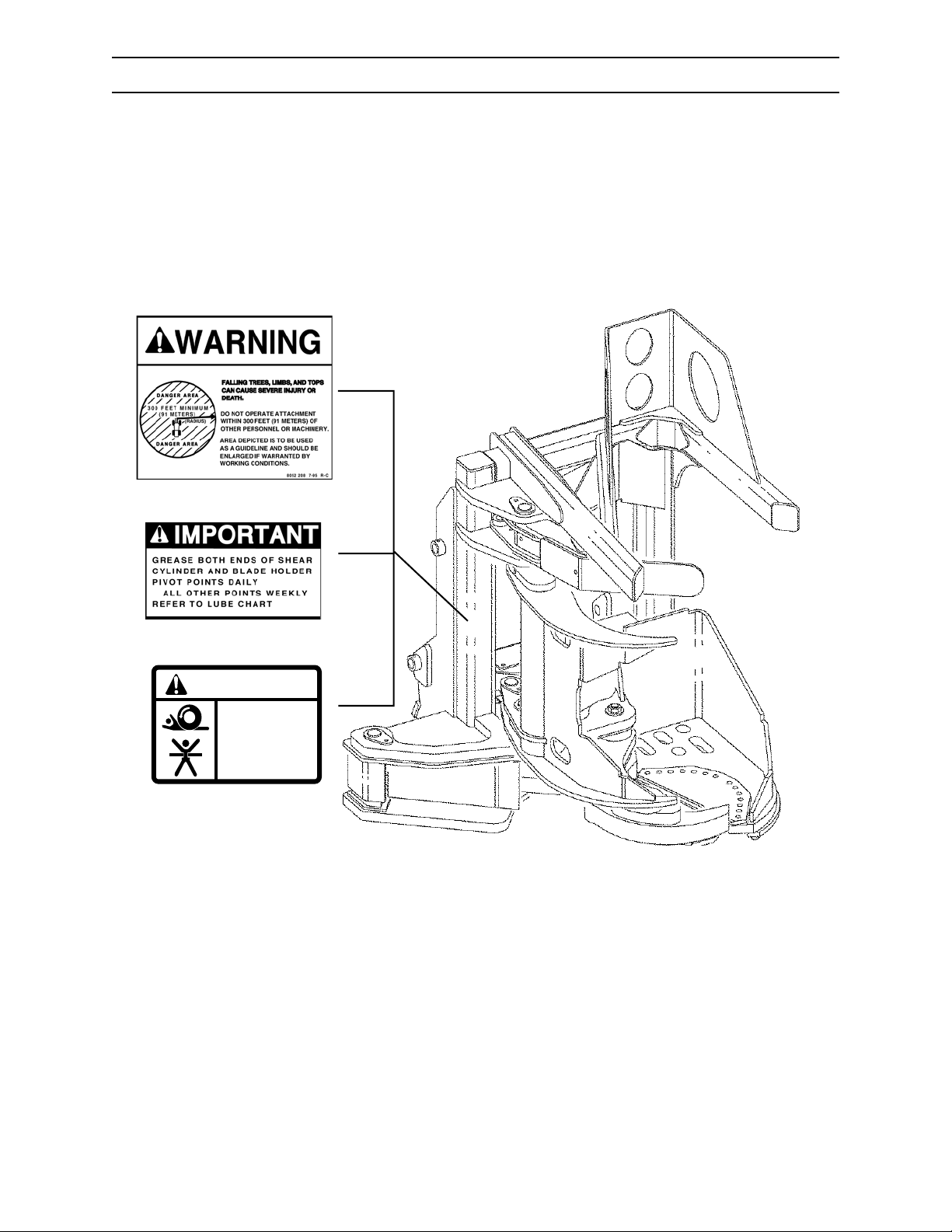
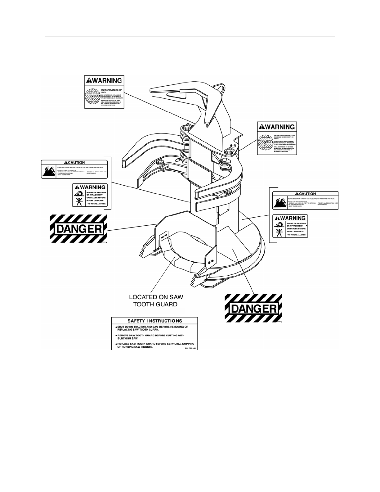
SAFETY DECALS
WARNING
RIDING ON TRACTOR
OR ATTACHMENT
CAN CAUSE SEVERE
INJURY OR DEATH
¥ NO RIDERS ALLOWED.
10051508 1-96
IF STEERING IS ACTIVATED WITH PERSON IN CENTER HINGE "CRUSH
POINT" AREA, SEVERE INJURY OR DEATH COULD OCCUR.
SAFETY DECALS
The following safety decals are located in positions on the machine as continual reminders of HAZARDS.
Serious injury or property damage can occur if safety instructions are not followed.
Keep all safety decals clean and readable. Use a soft cloth, water, and soap to clean decals if they are
too dirty to read. DO NOT clean safety decals with solvent. Solvent can damage them.
Replace safety decals immediately if they are damaged, missing, or hard to read. Contact your authorized
dealer for replacement safety decals. Your authorized dealer will provide free replacement safety decals if
you provide a valid serial number for your machine.
If you replace a part that has safety decal, apply a new safety decal to the
replacement part. Before putting a new decal on the machine or part, be sure the surface where decal will
be mounted is clean and dry.
2 REQUIRED
CAUTION
PRESSURIZED COOLING
SYSTEM.
CAN CAUSE SCALDING
BURNS.
ALLOW SYSTEM TO COOL.
REMOVE CAP SLOWLY
WITH GLOVES ON.
10008922
D.003.02
2 REQUIRED
CAUTION
PRESSURIZED WATER SYSTEM
1. PRESSURIZE WATER SYSTEM WITH COMPRESSED AIR TO A MAXIMUM PRESSURE OF
65 PSI
2. RELEASE PRESSURE BEFORE REMOVING TANK FILL PLUG
3. RELEASE PRESSURE BY LIFTING STEM ON RELIEF VALVE ON TANK FILL PLUG
4. RECHARGE WATER SYSTEM IMMEDIATELY AFTER USE
5. TO PREVENT FREEZING, ADD A NON-TOXIC RECREATIONAL VEHICLE PLUMBING
ANTI-FREEZE
6. PERFORM ALL REQUIRED MAINTENANCE ON WATER SYSTEM AS SPECIFIED IN
THE SERVICE MANUAL
2 REQUIRED
STAY BACK 300 FEET
4 REQUIRED
WARNING
FLUID ESCAPING UNDER PRESSURE
CAN PENETRATE SKIN AND CAUSE
SEVERE PERSONAL INJURY.
DO NOT DISCONNECT HOSES OR FITTINGS,
OR ATTEMPT SERVICING THE HYDRAULIC
ACCUMULATOR OR PILOT CIRCUIT
WITHOUT FIRST DISCHARGING THE
ACCUMULATOR.
10055037REV A11-97
D.009.02
2 REQUIRED
10059929 11-00
D.004.02
2570/2670 0906
WARNING
TRACTOR IS EQUIPPED WITH "QUICK STEER" SYSTEM AND MOVING THE
STEERING WHEEL COULD COMPLETELY TURN THE TRACTOR RIGHT OR LEFT.
DO NOT USE STEERING WHEEL OR JOYSTICK AS A HAND HOLD
WHEN MOUNTING OR DISMOUNTING TRACTOR.
INSTALL THE ARTICULATION LOCK BEFORE PERFORMING SERVICE OR
MAINTENANCE.
NEVER STAND IN THIS AREA WITH ENGINE RUNNING.
2 REQUIRED
10051314 11-00
D.008.02
WARNING
IMPROPERLY SECURED CAB LATCH PINS
CAN CAUSE SEVERE INJURY OR DEATH.
WHEN CAB IS COMPLETELY LOWERED INTO BRACKETS,
BOTH
RETAINING LOCK PIN PLATES AND
CAB LATCH PIN CAP SCREWS (GRADE 8) WITH
LOCKWASHERS MUST BE SECURELY TIGHTENED
TO ENSURE PROPER LOCKING AND ROLLOVER
PROTECTION (ROPS).
LH SIDE ONLY
ALL FOUR
D.007.02
2-1
10059878 11-*00
2 REQUIRED
CAUTION
THE BUILD UP OF DEBRIS INCREASES THE
RISK OF FIRE. REMOVE DEBRIS FROM ALL
COMPARTMENTS AFTER EACH 8 HOURS OF
OPERATION OR MORE OFTEN IF WARRANTED
BY WORKING CONDITIONS.
IN CASE OF FIRE
STOP VEHICLE
LOWER ATTACHMENT
STOP ENGINE
APPLY PARKING BRAKE
EXTINGUISH FIRE
2 REQUIRED
D.006.02
10052746 9-96
D.005.02
D.173.03
Page 28
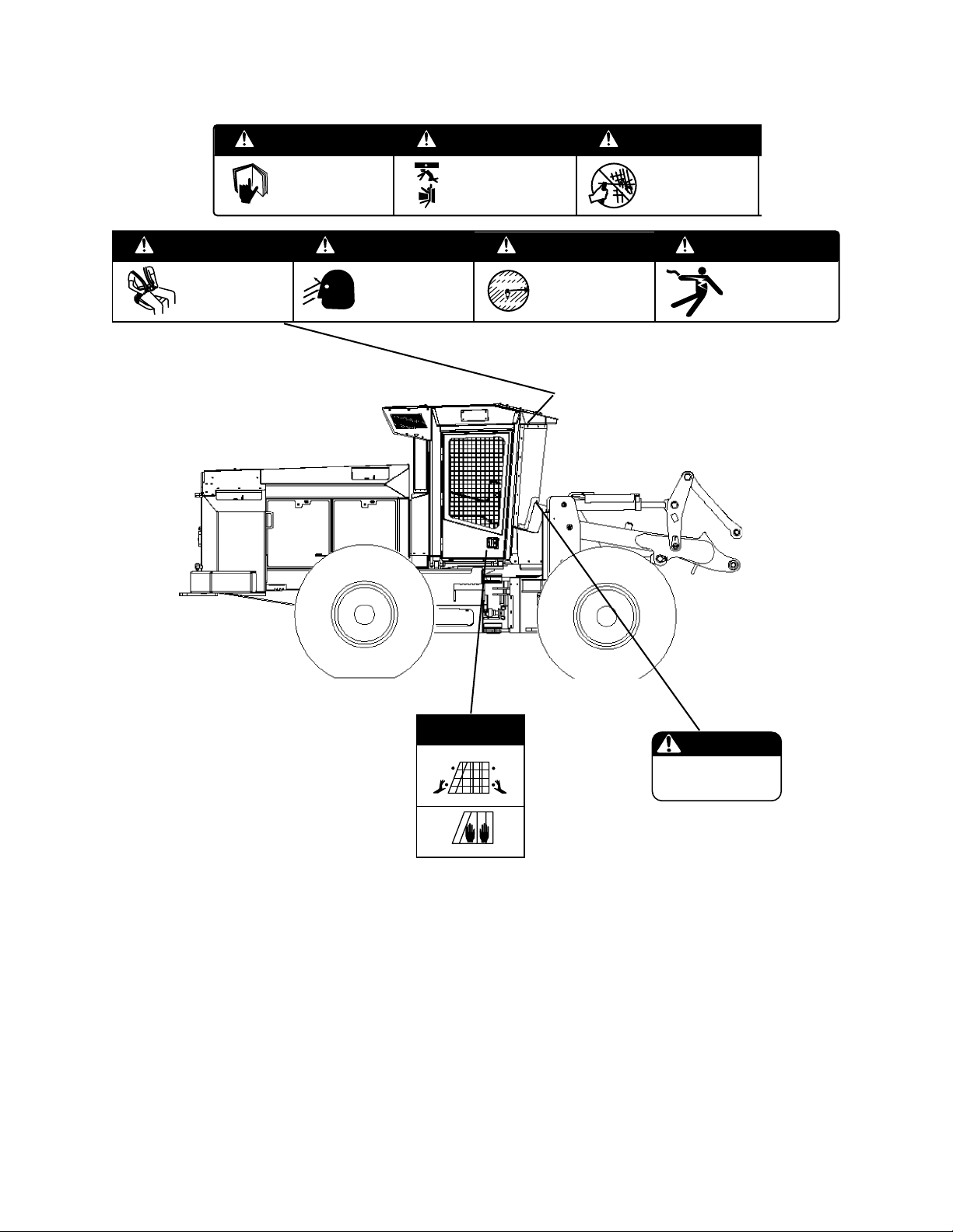
SAFETY DECALS
DANGER AREA
DO NOT USE ETHER
WARNING
WARNING
FAILURE TO WEAR SEAT BELT
CAN CAUSE SEVERE PERSONAL
INJURY OR DEATH.
FAILURE TO PROPERLY CENTER THE
SEAT BELT MAY RESULT IN FAILURE OF
THE SEAT BELT TO LOCK, ALLOWING THE
OPERATOR TO FALL FORWARD CAUSING
SERIOUS INJURY OR DEATH.
ALWAYS WEAR SEAT BELT (ADJUSTED
UNTIL SNUG) WHILE OPERATING THIS
MACHINE.
WARNING WARNING
UNSAFE OPERATION OR
MAINTENANCE CAN CAUSE
SEVERE INJURY OR DEATH.
DO NOT OPERATE OR WORK ON
THIS MACHINE WITHOUT
READING & UNDERSTANDING THE
OPERATOR’S MANUAL.
FALLING ATTACHMENT OR UNINTENDED
TRACTOR MOVEMENT CAN CAUSE
SEVERE INJURY OR DEATH.
BEFORE DISMOUNTING FROM MACHINE:
MOVE THE MACHINE TO LEVEL GROUND.
LOWER ATTACHMENT TO THE GROUND.
SET PARKING BRAKE.
SHUT OFF MACHINE.
RELIEVE HYDRAULIC PRESSURE.
REMOVE KEY FROM STARTER SWITCH.
-
WARNING WARNING
DEBRIS COMING THROUGH CAB
OPENINGS CAN CAUSE SEVERE
INJURY OR DEATH
WHILE OPERATING MACHINE:
KEEP CAB DOOR CLOSED.
ALL CAB OPENINGS (FRONT, SIDE AND
-
REAR) MUST BE COVERED WITH
@
LEXAN
WINDOW MATERIAL (NO GLASS)
AND/OR PROTECTIVE SCREEN.
DANGER AREA
300 FEET MINIMUM
(91 METERS)
FLYING DEBRIS, FALLING TREES, LIMBS,
AND TOPS CAN CAUSE SEVERE INJURY
OR DEATH.
DO NOT OPERATE ATTACHMENT
WITHIN 300 FEET (91 METERS)
OF PERSONNEL OR MACHINERY.
ALTERING ROPS/FOPS/OPS
STRUCTURE CAN CAUSE SEVERE
PERSONAL INJURY OR DEATH.
IF ROPS/FOPS/OPS STRUCTURE IS
DAMAGED (BENT OR CRACKED),
IT SHOULD BE INSPECTED BY
YOUR DEALER OR BY A FACTORY
REPRESENTATIVE. REPLACE ROPS/FOPS/OPS
STRUCTURE IF IT FAILS INSPECTION.
DO NOT ALTER ROPS/FOPS/OPS STRUCTURE.
WARNING
CONTACTING ELECTRIC LINES
WITH LIFT ARM, ATTACHMENT,
OR LOAD CAN CAUSE SEVERE
INJURY OR DEATH.
UNLAWFUL TO OPERATE THIS
MACHINE, LIFT ARM, ATTACHMENT, OR
LOAD WITHIN 10 FEET, PLUS
2 TIMES LINE INSULATOR LENGTH,
OF ANY ELECTRIC LINE.
10051398 Rev A 1-97
D.014.02
EMERGENCY
WINDOW EXIT
SAFETY INSTRUCTIONS
1. Loosen knobs until window guard releases.
2. Push against window until window falls out.
10062968 8/02
D.017.02
INSIDE
LH & RH CAB DOOR
2 REQUIRED
WARNING
ENGINE EQUIPPED WITH ELECTRIC
HEATER STARTING AID. USE OF
ETHER MAY CAUSE EXPLOSION AND
SEVERE INJURY.
ON DASH
10062491 02/02
D.016.02
2570/2670
2-2
0906
Page 29
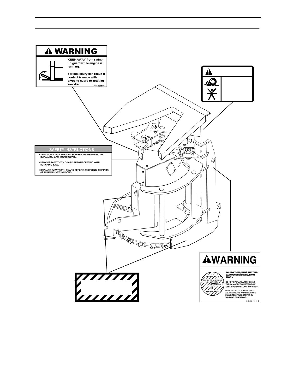
D.011.02
RIDING ON TRACTOR
OR ATTACHMENT
CAN CAUSE SEVERE
INJURY OR DEATH
SAFETY DECALS
SS56 SAW
2 REQUIRED
WARNING
2 REQUIRED
(1 decal on guard)
D.013.02
¥ NO RIDERS ALLOWED.
10051508 1-96
D.006.02
G.022.02
DANGER
2 REQUIRED
2570/2670 0906
2-3
2 REQUIRED
D.012.02
Page 30
SAFETY DECALS
RIDING ON TRACTOR
OR ATTACHMENT
CAN CAUSE SEVERE
INJURY OR DEATH
SH56 SAW
2 REQUIRED
D.012.02
WARNING
G.024.02
¥ NO RIDERS ALLOWED.
2 REQUIRED
10051508 1-96
D.006.02
2570/2670
DANGER
2 REQUIRED
2-4
D.013.02
2 REQUIRED (1 located on guard)
0906
Page 31
D.012.02
RIDING ON TRACTOR
OR ATTACHMENT
CAN CAUSE SEVERE
INJURY OR DEATH
SAFETY DECALS
RH54 SHEAR
D.015.02
WARNING
¥ NO RIDERS ALLOWED.
10051508 1-96
D.006.02
G.026.02
2570/2670 0906
2-5
Page 32
SAFETY DECALS
SC56 SAW
2570/2670
2-6
G.102.02
0906
Page 33
COMPONENT TERMINOLOGY
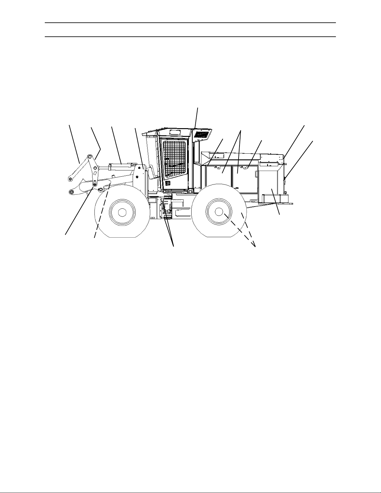
MACHINE
5
11
1
2
3
4
7
6
8
9
10
15
12
13
14
1. Link Arm
2. Tilt Link
3. Tilt Cylinder
4. Front Frame Towers
5. Cab
6. Battery Compartment
7. Side Panels
8. Muffler
2570/2670 0806
9. Fuel Tank (RH)
10. Radiator/Oil Cooler/Charged Air Cooler
11. Lift Arm
12. Lift Cylinder
13. Center Joint
14. Rear Axle Trunnions
15. Hydraulic Oil Reservoir (LH)
3-1
Page 34
10
COMPONENT TERMINOLOGY
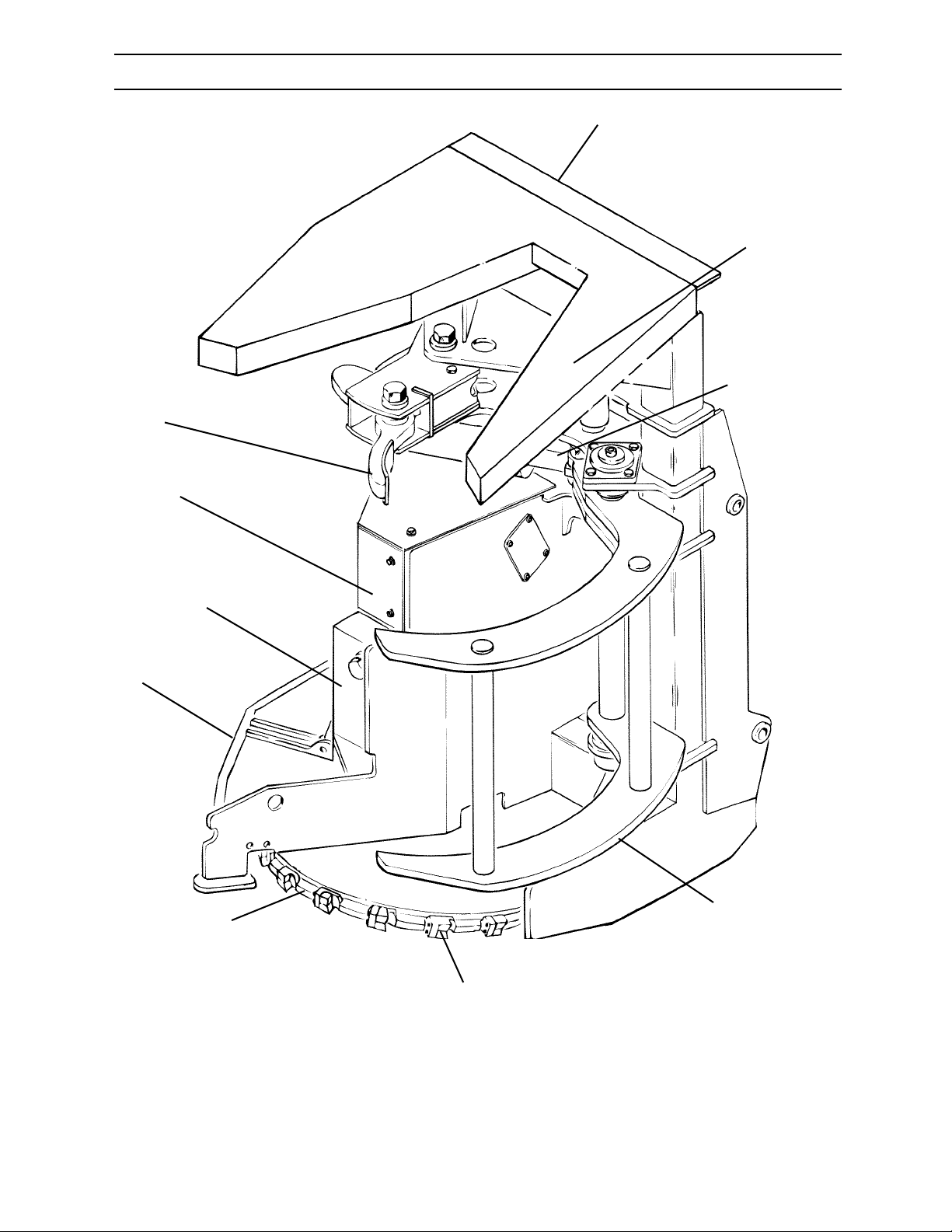
SS56 SAW
1
2
3
9
8
7
4
6
G.028.02
5
1. Main Frame
6. Saw Disc
2570/2670
2. Bunching Arm Cylinder
3. Gathering Arm Cylinder
4. Gathering Arm
5. Saw Tooth
3-2
7. Swing-Up Guard
8. Swing-Up Guard Cylinder
9. Saw Motor
10. Bunching Arm
0806
Page 35
COMPONENT TERMINOLOGY
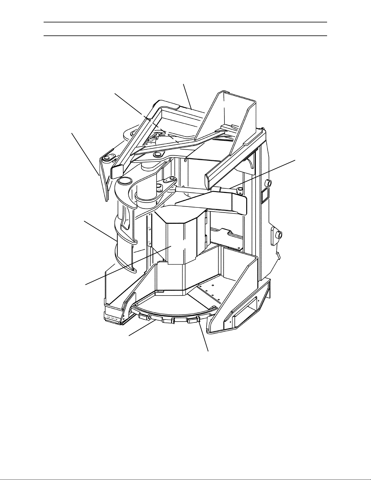
SH56 SAW
1
8
7
2
6
5
4
3
G.029.02
1. Main Frame
2. Gathering Arm Cylinder
3. Saw Tooth
4. Saw Disc
2570/2670 0806
3-3
5. Saw Motor
6. Gathering Arm
7. Bunching Arm
8. Bunching Arm Cylinder
Page 36
COMPONENT TERMINOLOGY
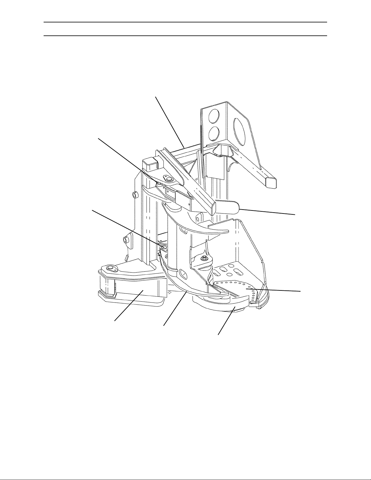
RH54 SHEAR
1
8
7
6
1. Main Frame
2
3
5
4
5. Gathering Arm
G.034.02
2570/2670
2. Bunching Arm
3. Shear Blade
4. Shear Blade Holder
3-4
6. Shear Cylinder
7. Gathering Arm Cylinder
8. Bunching Arm Cylinder
0806
Page 37
COMPONENT TERMINOLOGY
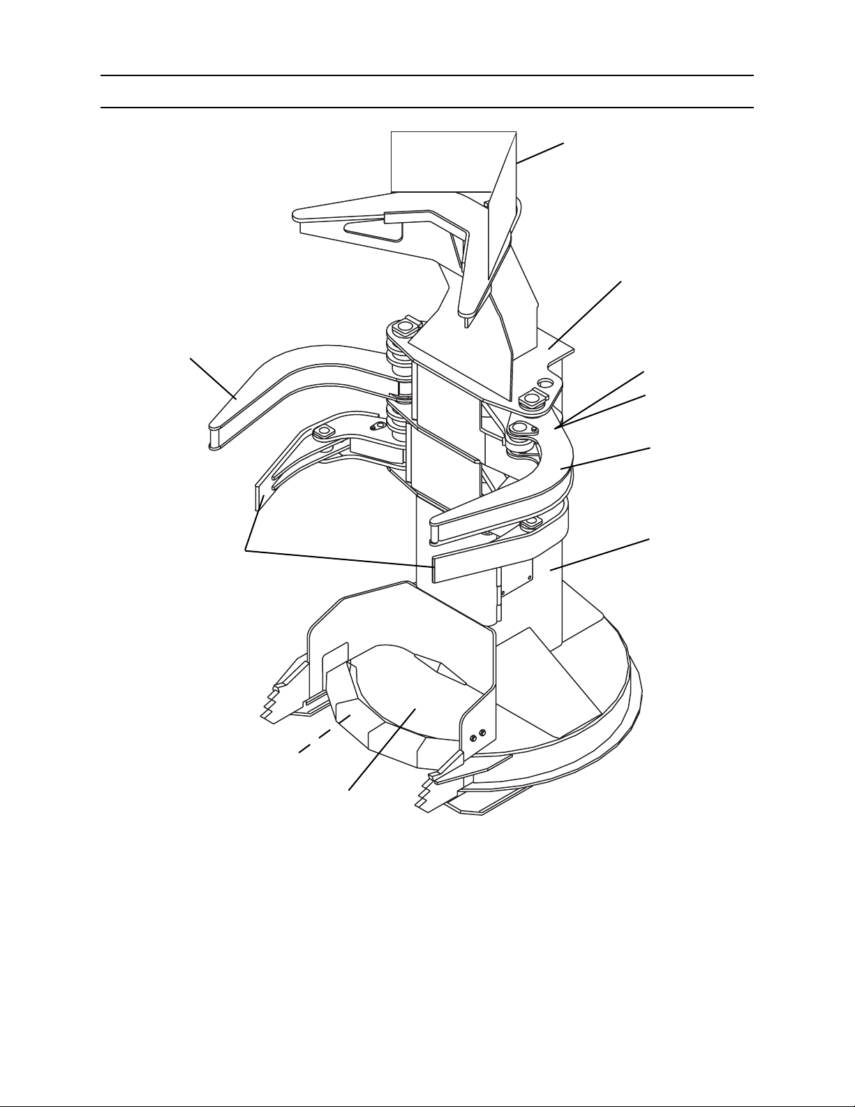
SC56 SAW
1
2
5
3
4
5
6
9
8
7
G.101.02
1. Top Limiter (optional)
2. Main Frame
3. Gathering Arm Cylinder
4. Bunching Arm Cylinder
5. Gathering Arm
2570/2670 0806
6. Saw Motor
7. Carrying Plate
8. Disc
9. Bunching Arm
3-5
Page 38

COMPONENT TERMINOLOGY
NOTES
2570/2670
3-6
0806
Page 39
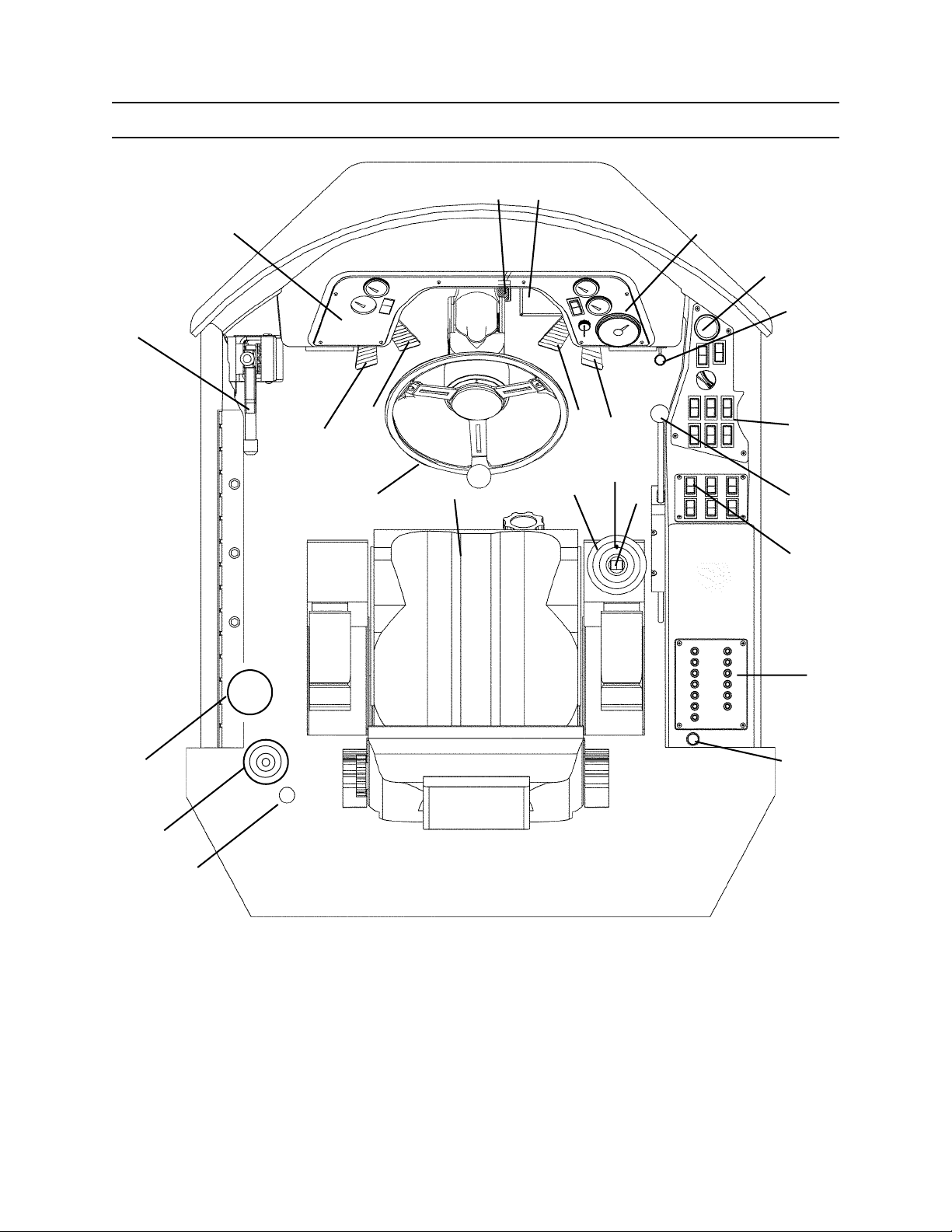
CONTROLS AND INSTRUMENTS
CONTROLS AND INSTRUMENTS
OPERATOR’S STATION (STEERING WHEEL)
D
C
A
B
G
M
H
N
O
E
F
K
I
J
L
P
Q
R
S
T
W
K
V
U
G.030.02
A. Parking Brake
B. Left Dash Panel
C. Service Brake Pedal
D. Master Cylinder
E. Right Dash Panel
F. Hourmeter
G. Gathering Arm Control - Open
H. Gathering Arm Control - Close
I. Reverse Propel Pedal
J. Forward Propel Pedal
K. Auxiliary Power Outlet
L. Right Console
2570/2670 0906
M. Steering Wheel
N. Seat
O. Joystick Control
P. Differential Lock - Front Axle
Q. Bunching Arm Control Switch
R. Transmission Shift Lever
S. Throttle
T. Circuit Breakers
U. Battery Disconnect Switch
V. Pressurized Water System
W. Fire Extinguisher
4-1
Page 40
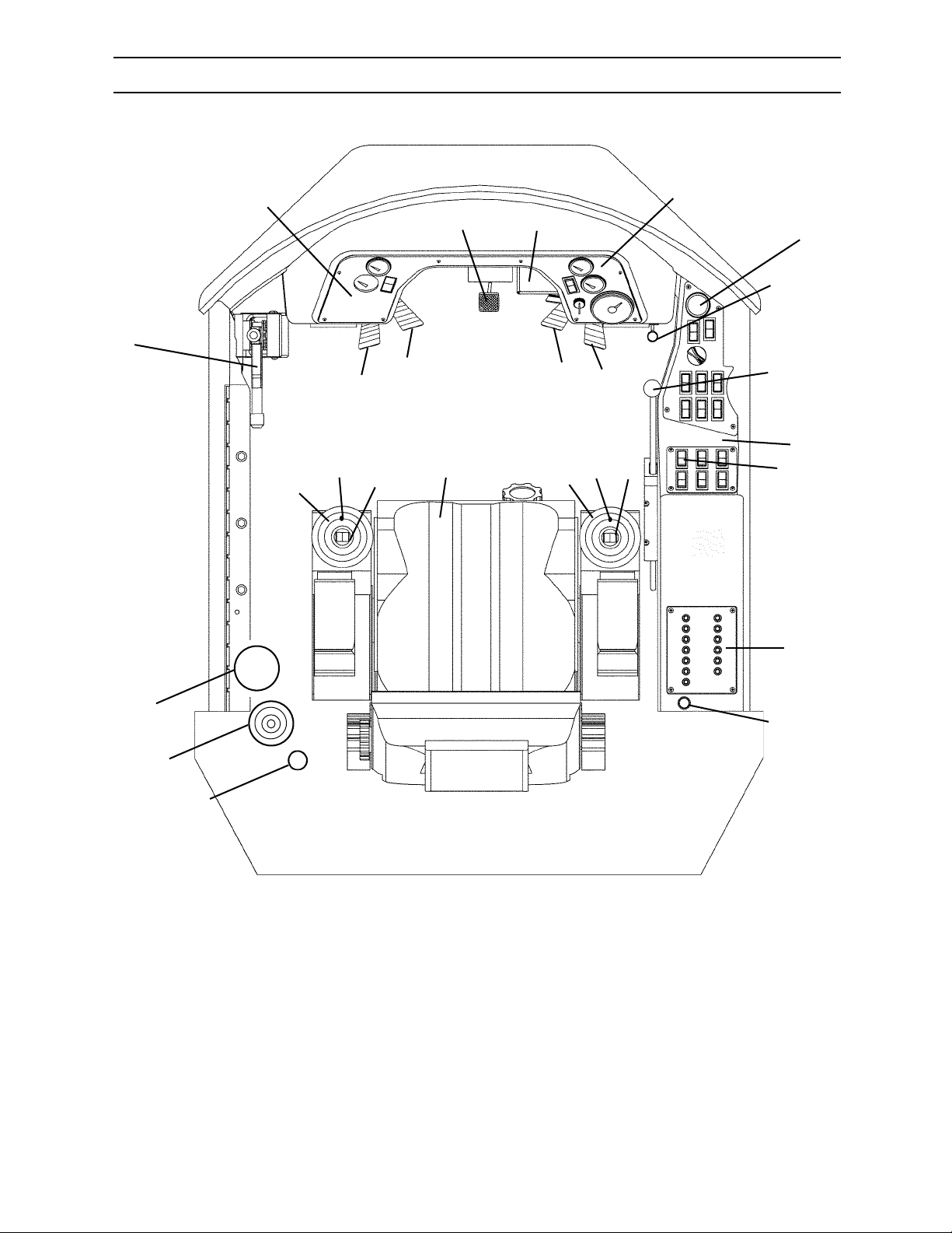
CONTROLS AND INSTRUMENTS
OPERATOR’S STATION (JOYSTICK STEERING)
A
B
N
O
G
P
H
CD
I
Q
R
S
E
F
K
J
L
M
T
U
Y
X
2570/2670
W
A. Parking Brake
B. Left Dash Panel
C. Service Brake Pedal
D. Master Cylinder
E. Right Dash Panel
F. Hourmeter
G. Gathering Arm Control - Open
H. Gathering Arm Control - Closed
I. Reverse Propel Pedal
J. Forward Propel Pedal
K. Auxiliary Power Outlet
L. Transmission Shift Lever
M. Right Console
G.169.02
N. Joystick Control - LH
O. Simultaneous Gathering and Bunching Arm
Open Switch
P. Gathering Arm Control Switch
Q. Seat
R. Joystick Control
S. Differential Lock - Front Axle
T. Bunching Arm Control Switch
U. Throttle
V. Circuit Breakers
W. Battery Disconnect Switch
X. Pressurized Water System
Y. Fire Extinguisher
4-2
V
K
0906
Page 41
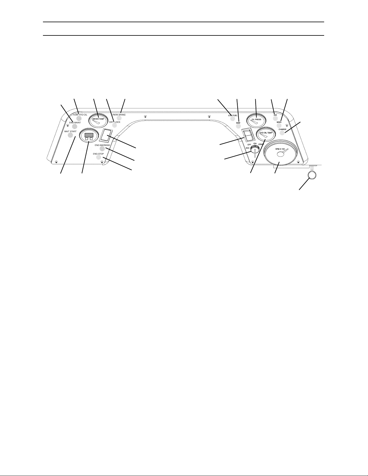
E
A
B
C
CONTROLS AND INSTRUMENTS
INSTRUMENT PANEL
D
K
L
M
N
O
P
G
I
J
H
LEFT DASH PANEL
A. Low Hydraulic Oil Warning Indicator
B. Water Temperature Gauge
C. Differential Lock Warning Indicator
D. Parking Brake Warning Indicator
E. Engine Maintenance Indicator
F. MDDM
G. Ether Start Switch
H. Wait to Start Indicator
I. Engine Warning Indicator
J. Engine Stop Indicator
F
Q
R
S
RIGHT DASH PANEL
K. Low Fuel Indicator Light
L. Saw Hydraulic Filter Warning Indicator
M. Engine Oil Pressure Gauge
N. Air Filter Warning Indicator
O. Main Hydraulic Filter Warning Indicator
P. Charge Hydraulic Filter Warning Indicator
Q. Engine Start/Attachment Run Switch
R. Ignition Switch
S. Hydraulic Oil Temperature Gauge
T. Saw Tachometer (optional)
U. Auxiliary Power Outlet
T
U
G.171.02
2570/2670 0906
4-3
Page 42
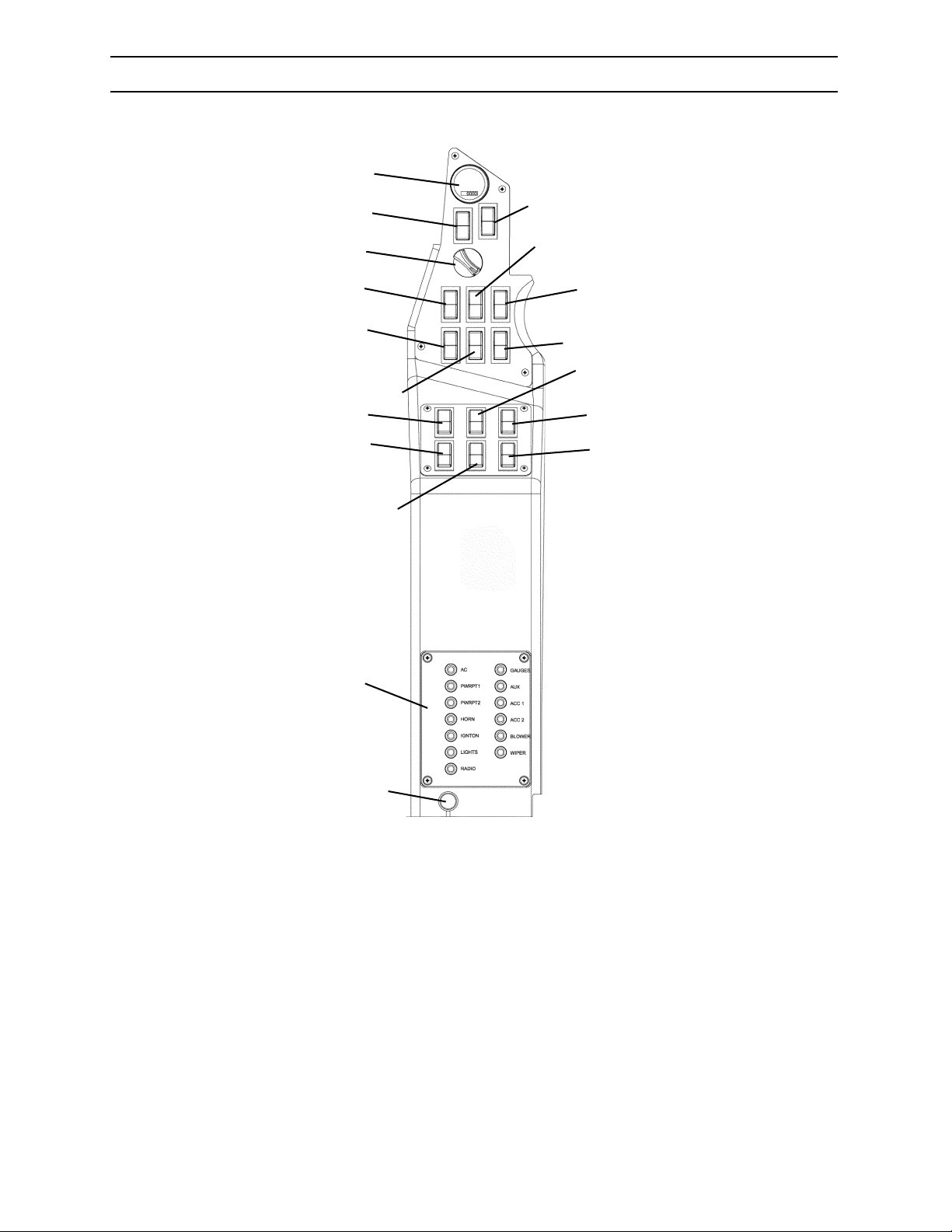
CONTROLS AND INSTRUMENTS
RIGHT CONSOLE
A
B
C
E
D
H
Q
K
N
F
G
J
L
I
M
P
O
2570/2670
R
A. Hourmeter
B. Not Used
C. Not Used
D. Heat/AC Temperature Control Knob
E. Heat/AC Selection Switch
F. Rear Axle Differential Lock
G. Not Used
H. Fan Speed
I. Hydrostatic Transmission Hi/Lo
G.170.02
J. Light Switch
K. Throttle
L. Not Used
M. Not Used
N. Horn Switch
O. Sidecut Saw Switch (option)
P. Override Switch
Q. Circuit Breaker Panel
R. Auxiliary Power Outlet
4-4
0906
Page 43
CONTROLS AND INSTRUMENTS
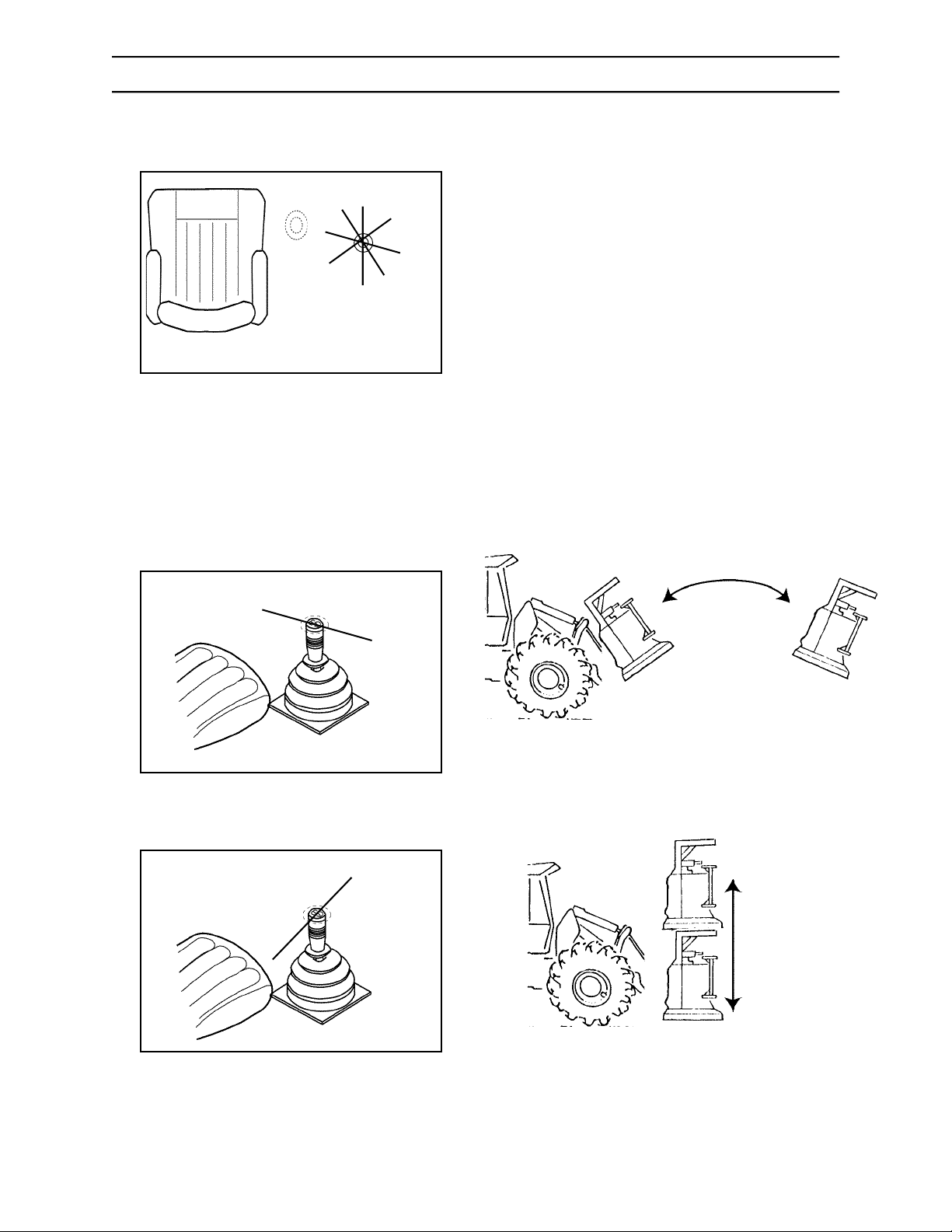
JOYSTICK CONTROL - RIGHT HAND (RH)
Use the joystick control lever to regulate the lift arm
and attachment as follows:
A. Lift arm down
B. Lift arm up
C. Tilt attachment forward
D. Tilt attachment back
E. Lift arm down - attachment tilt forward
F. Lift arm up - attachment tilt back
D
A
H
F
B
E
C
G
D
C
G.045.02
G.044.02
G. Lift arm up - attachment tilt forward
H. Lift arm down - attachment tilt back
The control lever is self-centering and will return to
neutral when handle is released.
D
G.036.02
C
A
B
B
A
G.036.02
G.044.02
2570/2670 0906
4-5
G.046.02
Page 44
CONTROLS AND INSTRUMENTS
BUNCHING ARM SWITCH
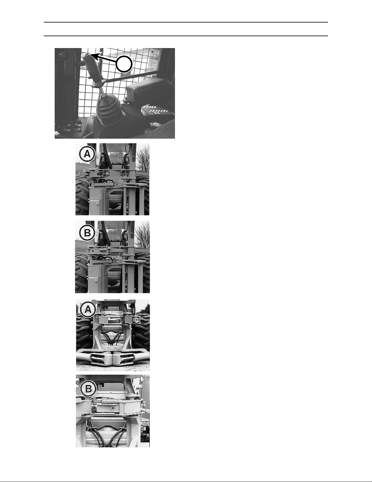
The rocker switch (A) located on top of the right
hand (RH) joystick controls the opening and closing
A
001.02
of the bunching arms.
SAW
Depressing switch to the left closes the
bunching arm (A).
Depressing switch to the right opens the
bunching arm (B).
056.02
057.02
058.02
SHEAR
Depressing switch to the left closes the
bunching arm (A).
Depressing switch to the right opens the
bunching arm (B).
2570/2670
059.02
4-6
0906
Page 45
CONTROLS AND INSTRUMENTS
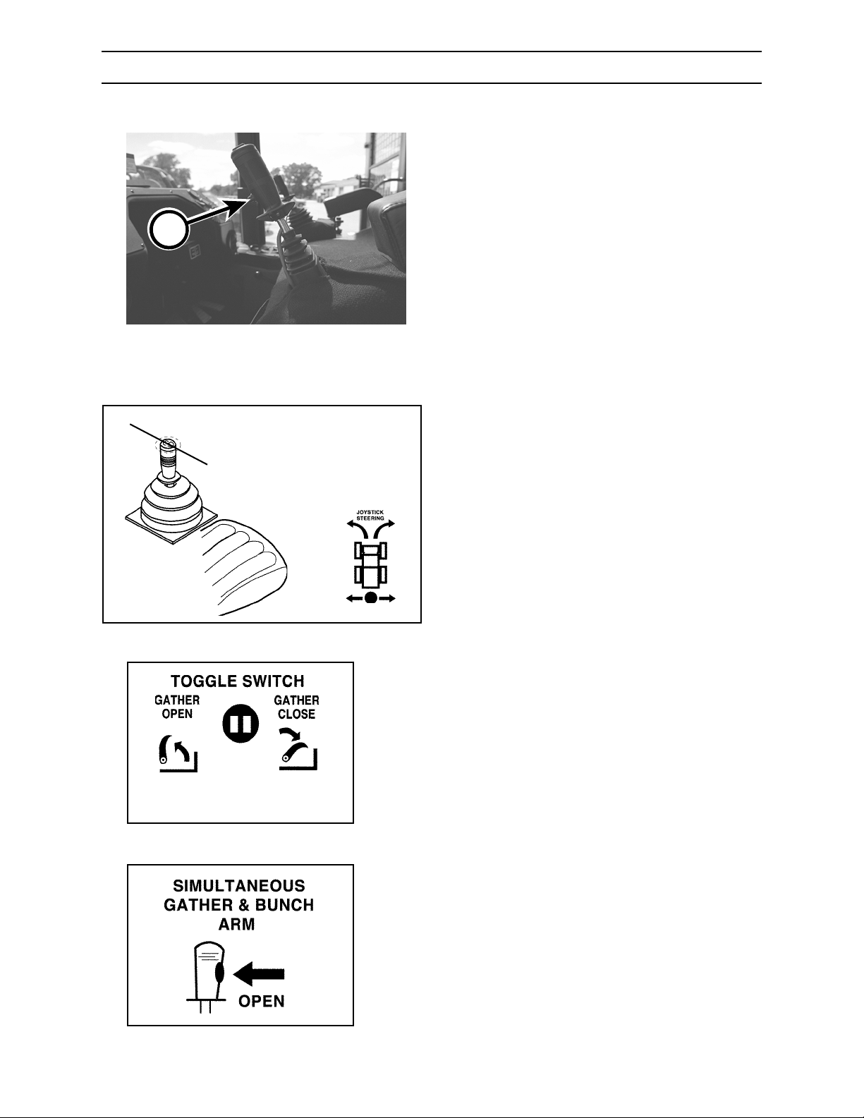
JOYSTICK CONTROL - LEFTHAND (LH) (OPTIONAL)
E
5/670.002.02
Left Hand Joystick - Quick Dump Button
B
A
G.037.02
LEVER
Use the left hand joystick control lever to operate
the tractor steering and gathering arm (optional) as
follows:
A. Steer right
B. Steer left
B
A
G.040.02
TOGGLE SWITCH
Use the toggle switch to operate the attachment
gathering arm as follows:
C. Gathering arm - close
D. Gathering arm - open
CD
G.041.02
BUTTON
Depress the quick dump button (E) at the same
time to open both the gathering arm and bunching
arm.
E. Quick dump button
E
G.038.02
2570/2670 0906
4-7
Page 46
CONTROLS AND INSTRUMENTS
PROPEL PEDALS
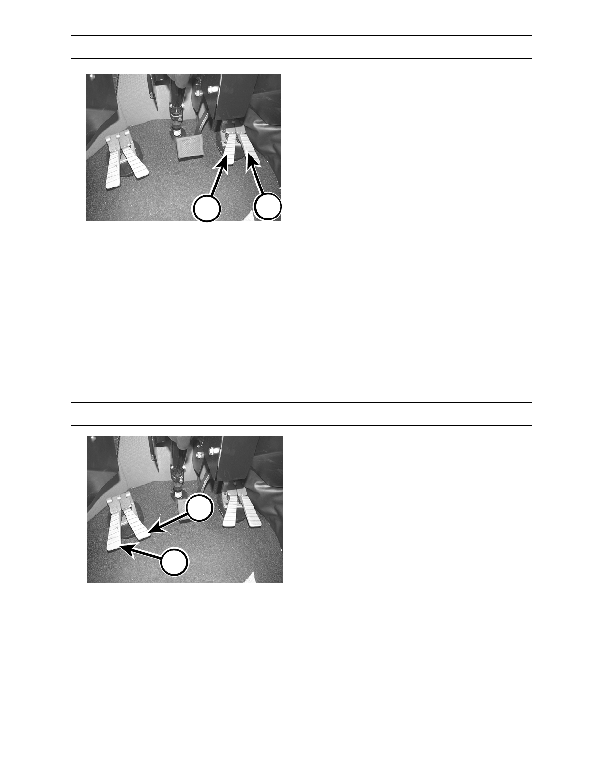
Depress pedal (A) for forward travel.
Depress pedal (B) for reverse travel.
Forward and reverse speeds are infinitely variable
from:
Low range 0 to 5 mph (0 to 8 kph)
High range 0 to 14 mph (0 to 22 kph)
B
A
5/670.003.02
SAW/SHEAR GATHERING ARM PEDALS
The gathering arm pedals open and close the
gathering arm.
2570/2670
C
D
5/670.003.02
4-8
0906
Page 47
CONTROLS AND INSTRUMENTS
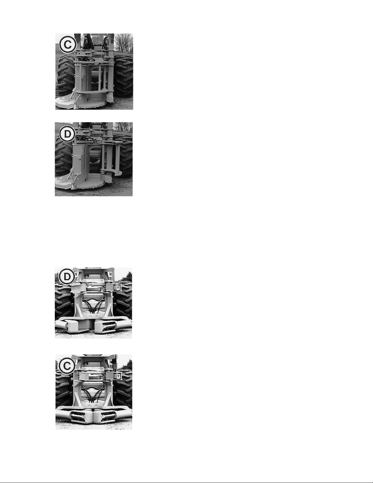
SAW
Depressing pedal (C) opens the gathering arm.
Depressing pedal (D) closes the gathering arm.
060.02
061.02
063.02
SHEAR
Depressing pedal (D) closes the gathering arm.
Continuing to hold pedal (D) down will cause shear
blades to close. As pressure increases to shear the
tree, pressure also increases on gathering arm to
hold the tree.
Depressing pedal (C) opens the gathering arm.
Continuing to hold pedal (C) down opens the right
shear blade first, then the left.
.062.02
2570/2670 0906
4-9
Page 48
A
CONTROLS AND INSTRUMENTS
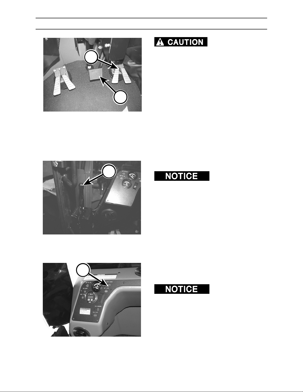
BRAKE PEDALS
Trying to stop machine
travel in one direction by depressing the pedal
for the opposite direction may cause machine
to come to a stop and to move abruptly in the
opposite direction. Dynamic braking is best
controlled by simply removing your foot from
propel pedals.
DYNAMIC BRAKING
C
B
5/670.003.02
5/670.004.02
Remove foot from propel pedals (A). This results in
dynamic braking.
EMERGENCY OR SERVICE BRAKE
Depress pedal (B) for emergency or service
braking.
PARKING BRAKE
DO NOT operate
machine with parking brake set. Doing so will
damage parking brake and may cause a fire.
To set parking brake, pull lever (C) up to the
vertical, locked position.
To release parking brake, push lever down
completely.
2570/2670
D
The parking brake indicator (D) will light when
parking brake handle is in the vertical and locked
position.
Parking brake must be
set to start engine, and must be completely
released to propel machine. If parking brake does
not function in this manner, immediately contact
yan authorized dealer for system repair.
4-10
0906
Page 49
CONTROLS AND INSTRUMENTS
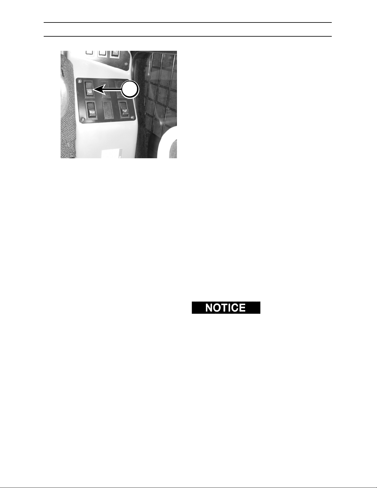
THROTTLE
Operate engine at FULL throttle.
Engine must run at FULL throttle for the following
reasons:
1. Doing so ensures proper cooling of engine and
A
2. Doing so ensures proper volume and pressure
3. Doing so ensures full oil flow to hydraulic
The throttle (A) controls governed engine speed
from low idle to full governed speed as follows:
2570
2670
hydraulic system.
of oil to hydrostatic components.
circuits.
Full Load
Low Idle rpm Governed rpm
Cummins 950 2400
Cummins 1000 2200
INCREASING ENGINE SPEED
Push the toggle switch forward and hold to
increase engine speed. The engine speed with
ramp up while the toggle switch is depressed
forward.
DECREASING ENGINE SPEED
Push toggle switch back and hold to decrease
engine speed. The engine speed will ramp down
while the toggle switch is depressed to the rear.
Throttle can be finetuned by momentarily depressing the throttle toggle
switch in the corresponding direction.
2570/2670 0906
4-11
0106
0106
Page 50
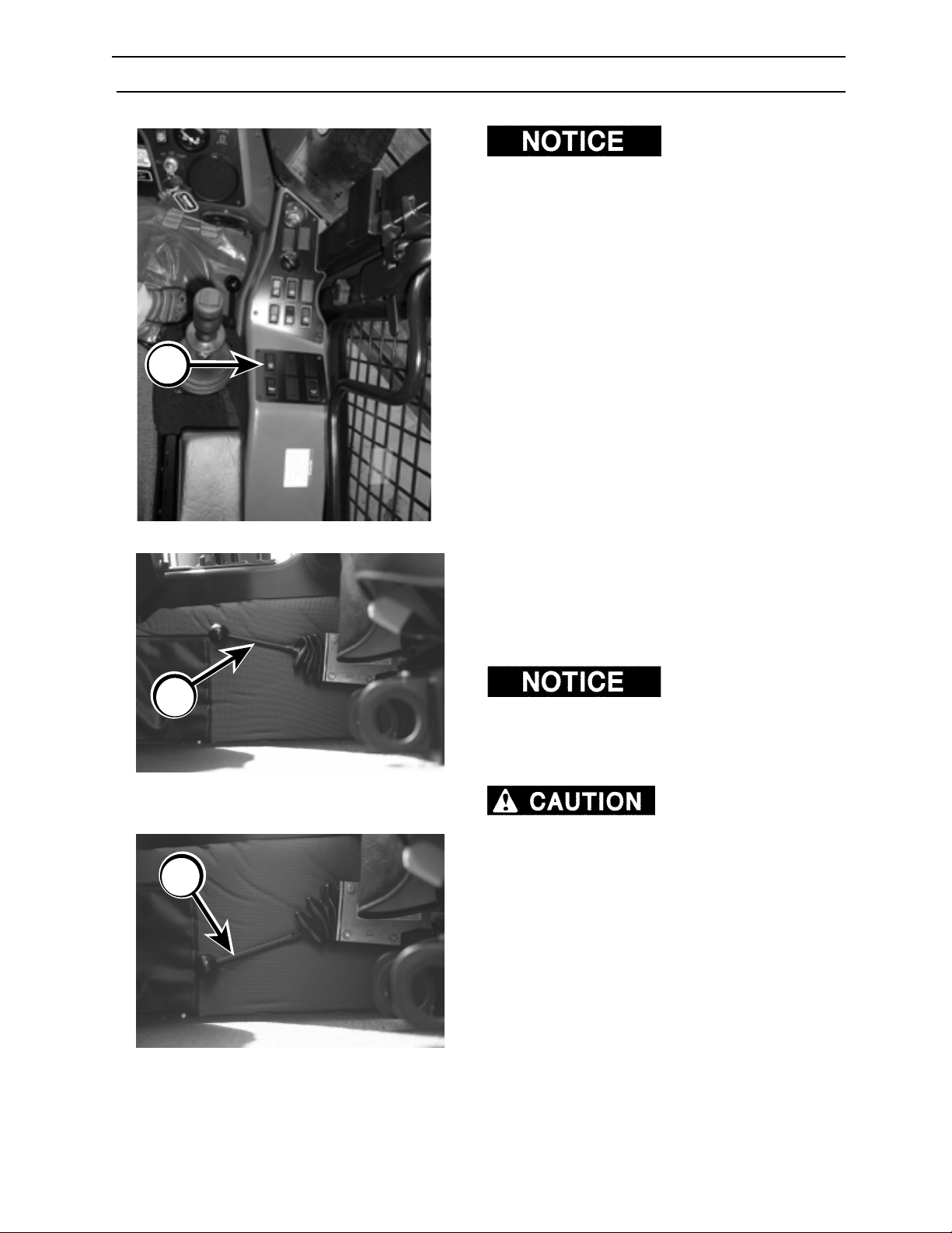
A
CONTROLS AND INSTRUMENTS
TRANSMISSION SHIFT CONTROL
moving will cause transmission damage and VOID
your warranty. When shifting transmission,
•
completely stop tractor,
• make sure propel pedals are in neutral
position,
• depress throttle switch to LOW IDLE position,
and;
• move transmission shift lever to desired
position.
The 2-speed transmission is a non-sychronous
gear type. Transmission must ONLY be shifted with
machine at a complete stop, propel pedals in
NEUTRAL, and engine at LOW IDLE.
1. Completely stop machine.
2. Make sure propel pedals are in NEUTRAL
position.
3. Depress throttle switch (A) to LOW IDLE
92603.05
position.
4. Once tractor is completely stopped, move shift
lever into HIGH (B) or LOW (C)
Shifting while tractor is
B
5. Tractor may need to be articulated to complete
the shift. Do not use propel pedals to align
gears. Doing so will cause transmission
damage.
If you are using joystick
steering, to complete the shift, you may have to
articulate (steer) and slowly depress and release
shift control button to desired gear position multiple
times while steering.
5/670.054.02
When parking tractor,
always lower attachment to the ground and set
parking brake. DO NOT rely on the
transmission to hold machine while parked.
C
2570/2670
5/670.055.02
4-12
0906
Page 51
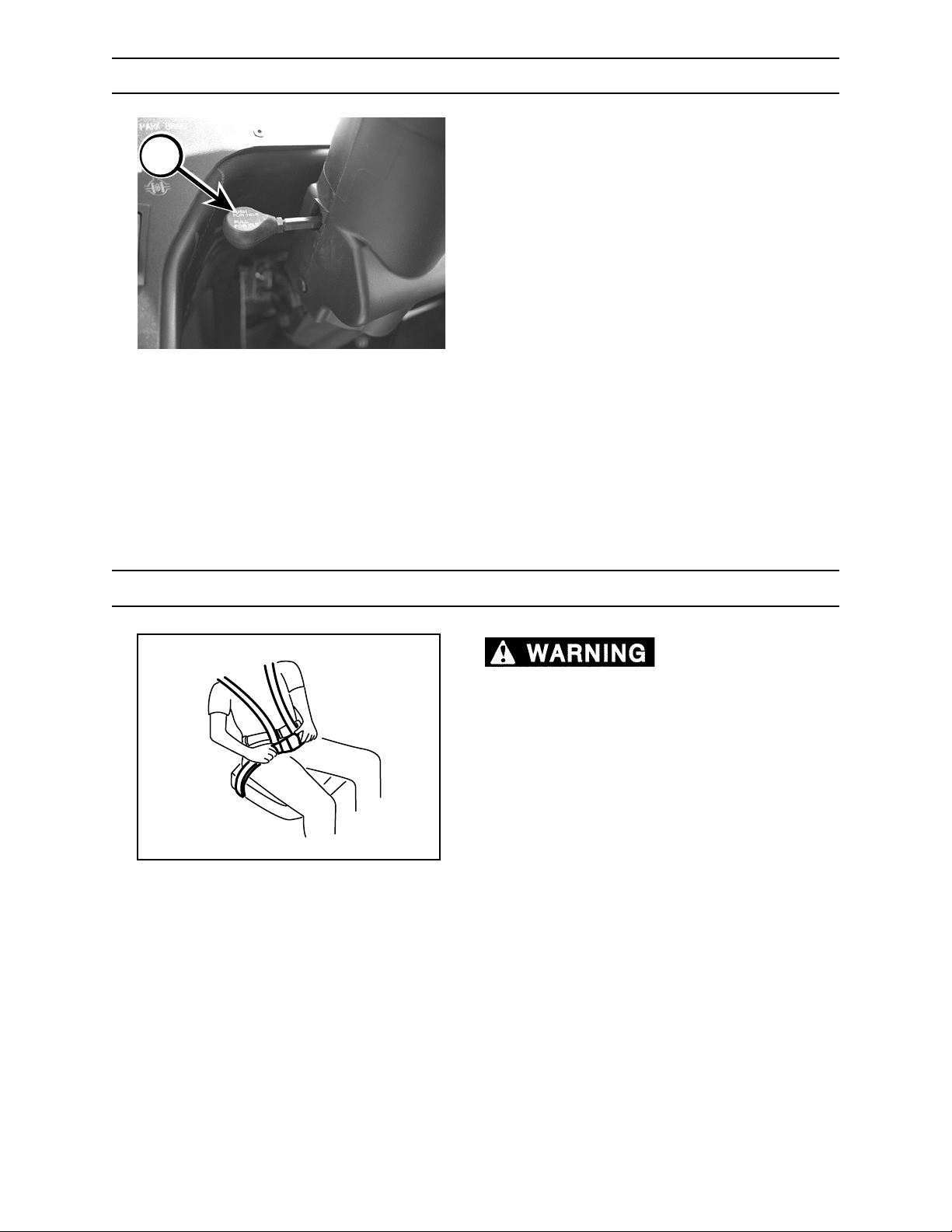
A
CONTROLS AND INSTRUMENTS
STEERING COLUMN
ADJUSTING TELESCOPING STEERING
COLUMN
1. Push lever (A) to unlock column.
2. Position steering wheel to desired height.
3. Release lever.
Make sure steering column is locked before
operating.
ADJUSTING STEERING COLUMN TILT
5/670.008.02
SEAT BELT
1. Pull lever (A) UP to unlock steering column.
2. Move steering wheel to desired position.
3. Release lever.
Failure to wear seat belt
can cause severe personal injury or death.
Failure to properly center seat belt may result
in failure of the seat belt to lock, allowing
operator to fall forward, causing serious injury
or death.
Always wear seat belt, adjusted snugly, while
operating this machine.
BEFORE OPERATING THIS MACHINE
1. Use the seat adjustments for proper operating
control and comfort.
2. Test seat belt for holding and release action.
3. Fasten seat belt and adjust until snug.
2570/2670 0906
4-13
Page 52
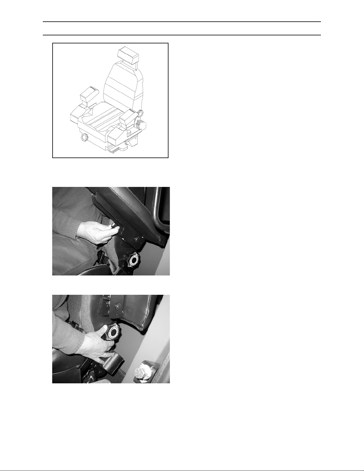
CONTROLS AND INSTRUMENTS
OPERATOR SEAT
Adjust your operator’s seat using the following
guidelines.
G.141.02
ADJUSTING ARMREST
5/670.237.02
Rotate control knob to select desired armrest
angle.
Pivot armrest up and parallel with backrest when
not in use.
ADJUSTING BACKREST
Rotate control knob to select desired backrest
position.
2570/2670
5/670.238.02
4-14
0906
Page 53
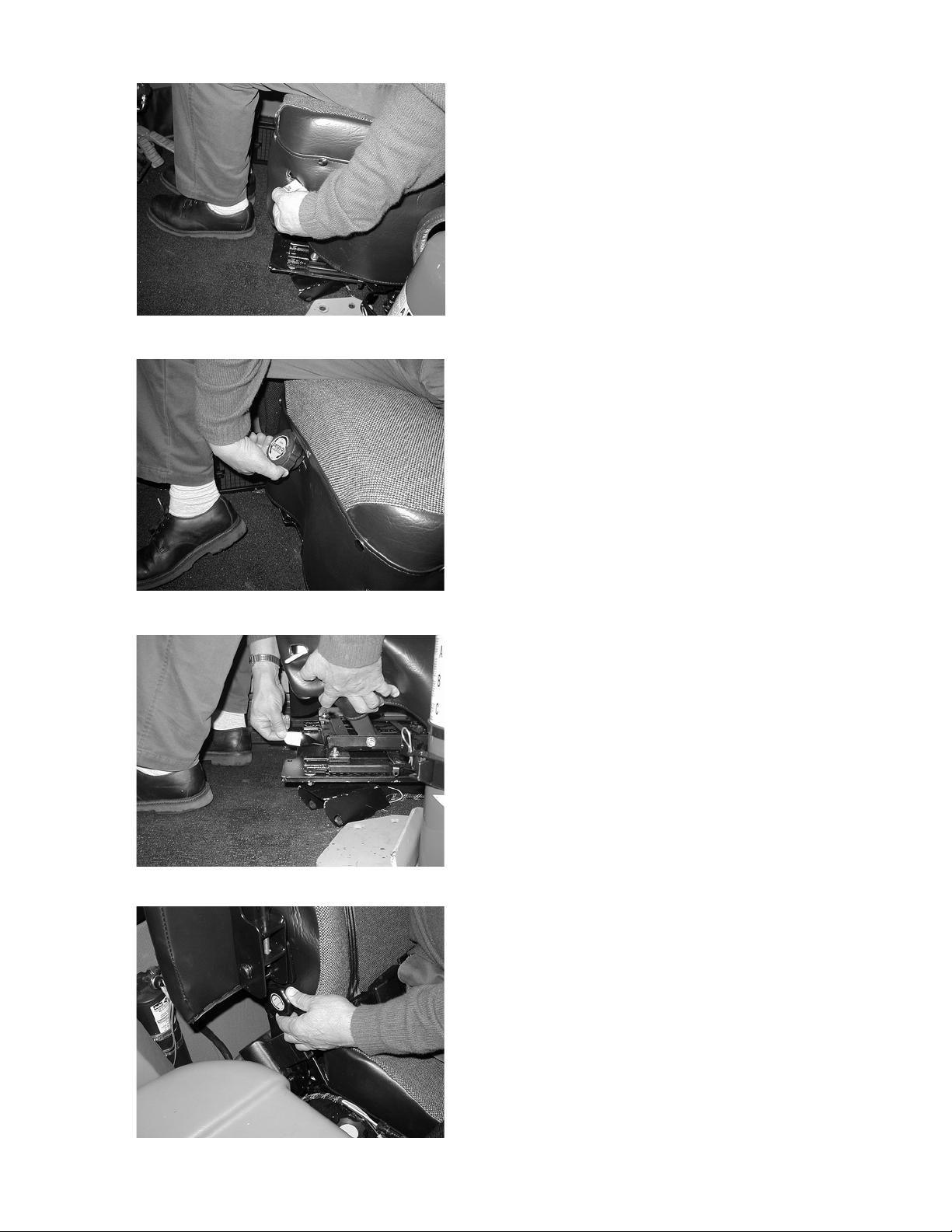
CONTROLS AND INSTRUMENTS
ADJUSTING SEAT HEIGHT
Firmly lift up and hold adjustment lever until lever
releases.
While holding lever in the UP position, adjust seat
to desired height by adding or removing your body
weight to the front or rear of seat cushion.
Firmly push DOWN on lever until seat locks (a click
will be heard).
5/670.239.02
ADJUSTING SEAT SUSPENSION
Rotate handwheel until seat cushion is level.
5/670.240.02
5/670.241.02
ADJUSTING SEAT FRONT AND REAR
POSITION
Lift lever UP and hold.
Slide seat to desired position.
Release lever.
ADJUSTING LUMBAR SUPPORT
Rotate handwheel to desired position.
5/670.242.02
2570/2670 0906
4-15
Page 54
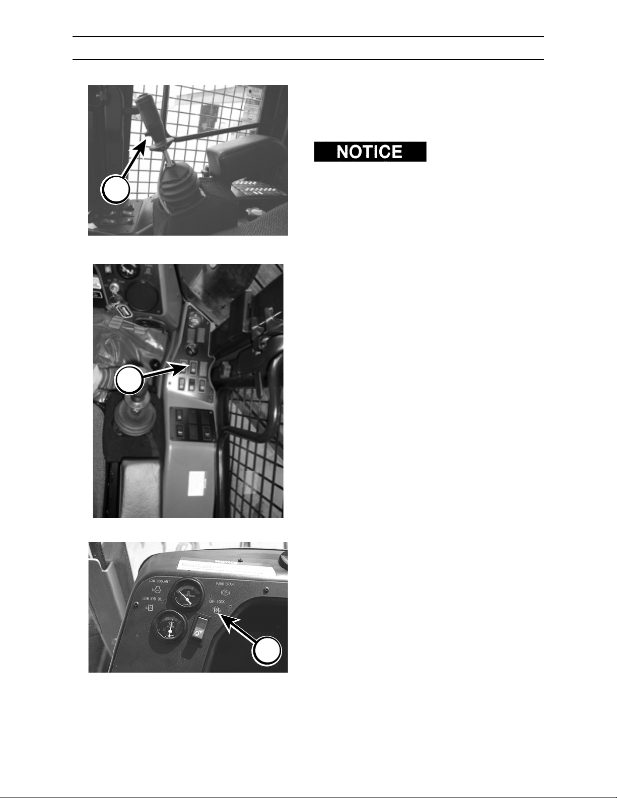
A
CONTROLS AND INSTRUMENTS
AXLE DIFFERENTIAL LOCK
The differential lock directs power equally to both
wheels on the axle by locking out the differential.
This prevents the usual loss of traction when one
wheel is slipping.
Lock the front and rear
axles ONLY in low traction conditions. Axle damage
can result if differential is locked at all times.
Differential can be locked or unlocked “on the fly.”
LOCKING FRONT AXLE
Front Axle Differential Lock
B
Rear Axle Differential Lock
5/670.001.02
92603.05
Depress button (A) on right hand joystick control.
Differential lock indicator (C) will light when front
axle is locked.
UNLOCKING FRONT AXLE
Release button (A) on right hand joystick control.
LOCKING REAR AXLE
Depress bottom portion of differential switch (B).
Differential lock warning indicator (C) will light when
rear axle is locked.
UNLOCKING REAR AXLE
Depress top portion of differential switch (B).
PROPER OPERATION OF DIFFERENTIAL
LOCKS
1. For best maneuverability and the least strain
on power train, run with both axles unlocked
whenever possible.
2. Engage front axle differential only as needed.
3. In severe terrain, lock rear differential.
Differential Lock Warning Indicator
2570/2670
C
5/670.016.02
4-16
0906
Page 55
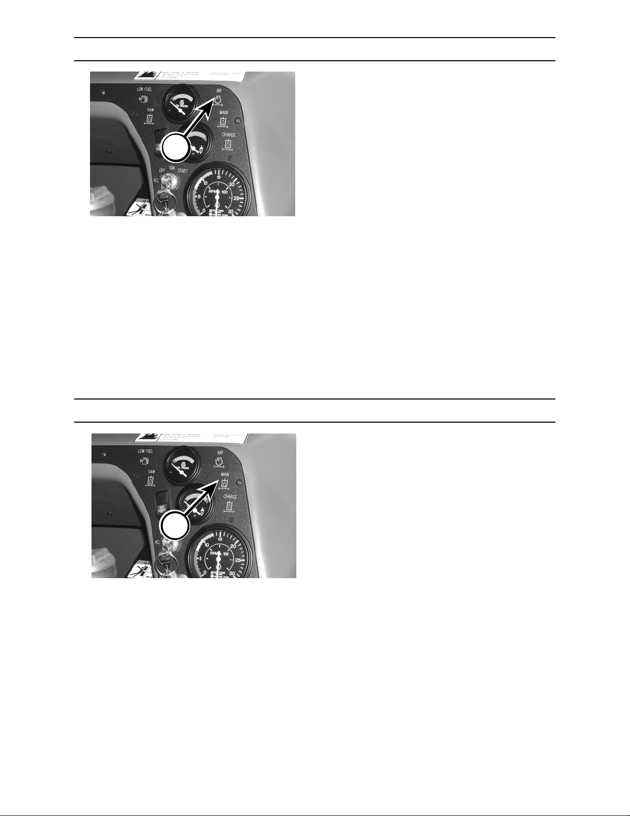
CONTROLS AND INSTRUMENTS
AIR FILTER WARNING INDICATOR
The air filter warning indicator (A) will light when
engine air filter is plugged and requires cleaning or
replacement. Once air filter is serviced, indicator
light will go off.
In high humidity conditions, indicator may register a
A
false reading.
See Section 11, Scheduled/Periodic Maintenance
Services, for proper air filter maintenance.
MAIN HYDRAULIC FILTER WARNING INDICATOR
The main hydraulic filter warning indicator (B) lights
when the hydraulic return line filter is restricted and
requires replacement. Once filter is serviced,
indicator light will go off.
The indicator will light at initial start up until
hydraulic oil reaches normal operating
temperature.
B
If indicator continues to light, oil is bypassing the
return line filter and going directly into the tank
without being filtered through the return line filter.
Return line filter should be changed immediately to
prevent damage to hydraulic components. See
Section 11, Scheduled/Periodic Maintenance
Services for proper filter replacement.
2570/2670 0906
4-17
Page 56
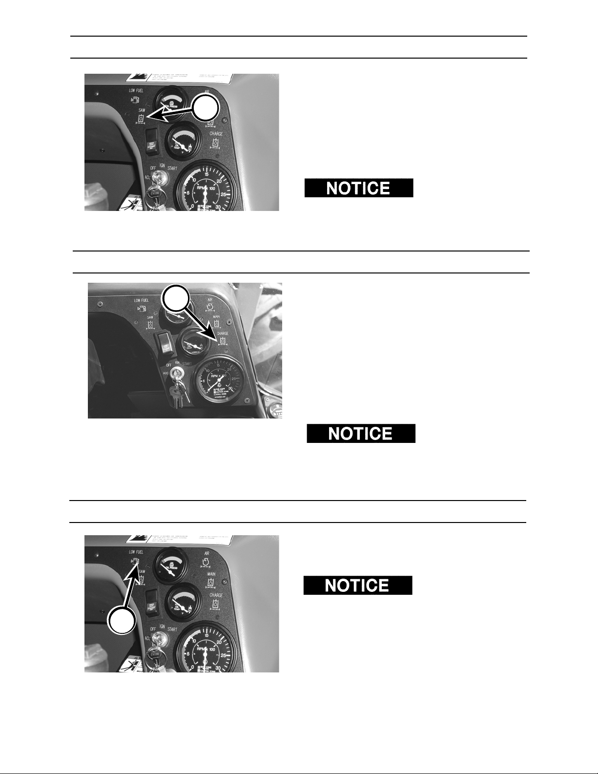
CONTROLS AND INSTRUMENTS
SAW HYDRAULIC FILTER WARNING INDICATOR
When hydraulic filter warning indicator (A) lights,
the saw hydraulic filter is plugged and needs to be
replaced. Refer to Section 12, Periodic
A
Maintenance - Attachments, for proper servicing of
filter. Once filter is serviced, indicator light will go
off.
In cold temperatures, indicator may register a false
reading.
Applicable to tractors
equipped with 18HC, 22SC or 22HC saws only.
CHARGE HYDRAULIC FILTER WARNING INDICATOR
When filter warning indicator (A) lights, the charge
A
hydraulic filter is plugged and needs to be
replaced. For proper filter replacement, refer to
Section 11, Scheduled/Periodic Maintenance
Services. Once the filter is serviced, indicator light
will go off.
B
In cold temperatures, indicator may register a false
reading.
Applicable to tractors
equipped with SH48, SH56, SS56 or SC56 saws
only.
LOW FUEL WARNING INDICATOR
The low fuel warning indicator (B) will light when
there is approximately ten (10) gallons (37.8 L) of
fuel left in the tank. Fill tank immediately.
DO NOT allow a diesel
engine to run out of fuel. Doing so will cause
engine damage.
2570/2670
4-18
0906
Page 57
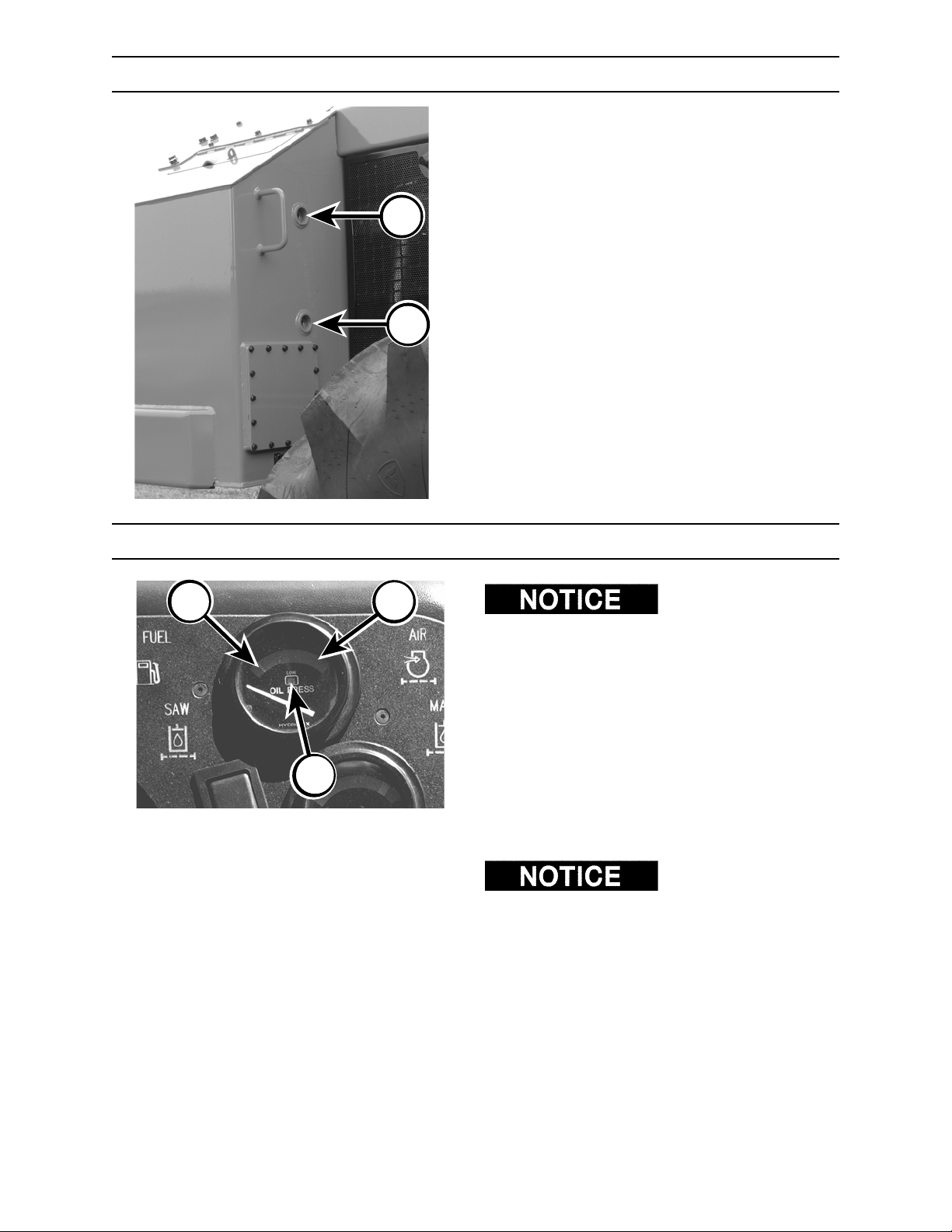
CONTROLS AND INSTRUMENTS
FUEL TANK SIGHT GAUGES
The fuel tank has two sight gauges. If fuel is visible
in the top gauge (A) you have a full tank; if fuel is
not visible in the bottom gauge (B) fuel should be
added. It takes approximately 29 gallons (110L) of
diesel fuel to raise fuel level from the bottom to the
A
top gauge.
B
B
ENGINE OIL PRESSURE GAUGE
A
indicated in ten (10) to fifteen (15) seconds at start
up, stop engine and check the lubricating oil
system.
At normal operating temperature, needle will point
to the green zone (A).
If the needle moves to the red zone (B), or if the
low pressure indicator (C) lights, shut engine down
C
5/670.027.02
immediately and contact an authorized dealer for
diagnosis and repair.
For more information, refer to your engine
operator’s manual.
guarantee a sufficient amount of oil in the engine
oil pan. Check engine oil level by observing level
on the engine oil dipstick.
If NO oil pressure is
Oil pressure DOES NOT
2570/2670 0906
4-19
Page 58
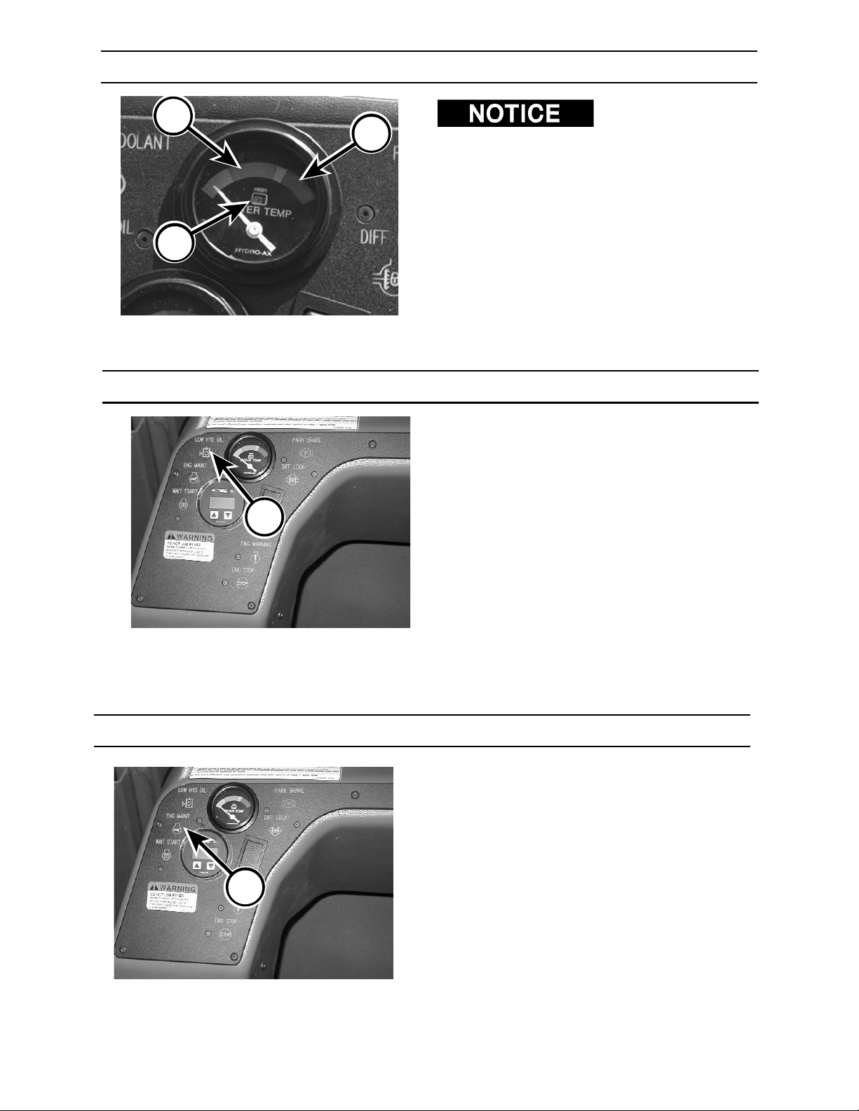
CONTROLS AND INSTRUMENTS
WATER TEMPERATURE GAUGE
A
C
Failure to reduce load
B
5/670.028.02
with the needle in the red zone or with the high
temperature warning indicator lit could cause
premature engine failure or damage.
At normal operating temperature, the needle will
point in the green zone (A).
If the needle moves to the red zone (B), or of the
high temperature indicator (C) lights, reduce load
immediately and adjust throttle to low idle. Shut
down engine and check for coolant leakage and/or
plugged radiator.
LOW HYDRAULIC OIL WARNING INDICATOR
The low hydraulic oil warning indicator light (A) will
light when there is approximately 31 gallons (117 L)
of hydraulic oil left in the reservoir.
Fill reservoir immediately to prevent damage to the
hydrostatic/hydraulic components.
A
To fill hydraulic reservoir, refer to Section 11,
Scheduled/Periodic Maintenance Services.
5/670.276.02
ENGINE MAINTENANCE WARNING INDICATOR
The maintenance warning indicator (B) will light up
when an error has been sensed by the engine
electronic control module.
When the indicator lights, refer to section 14
Troubleshooting for a complete list of error codes
and causes.
D
5/670.276.02
2570/2670
4-20
0906
Page 59
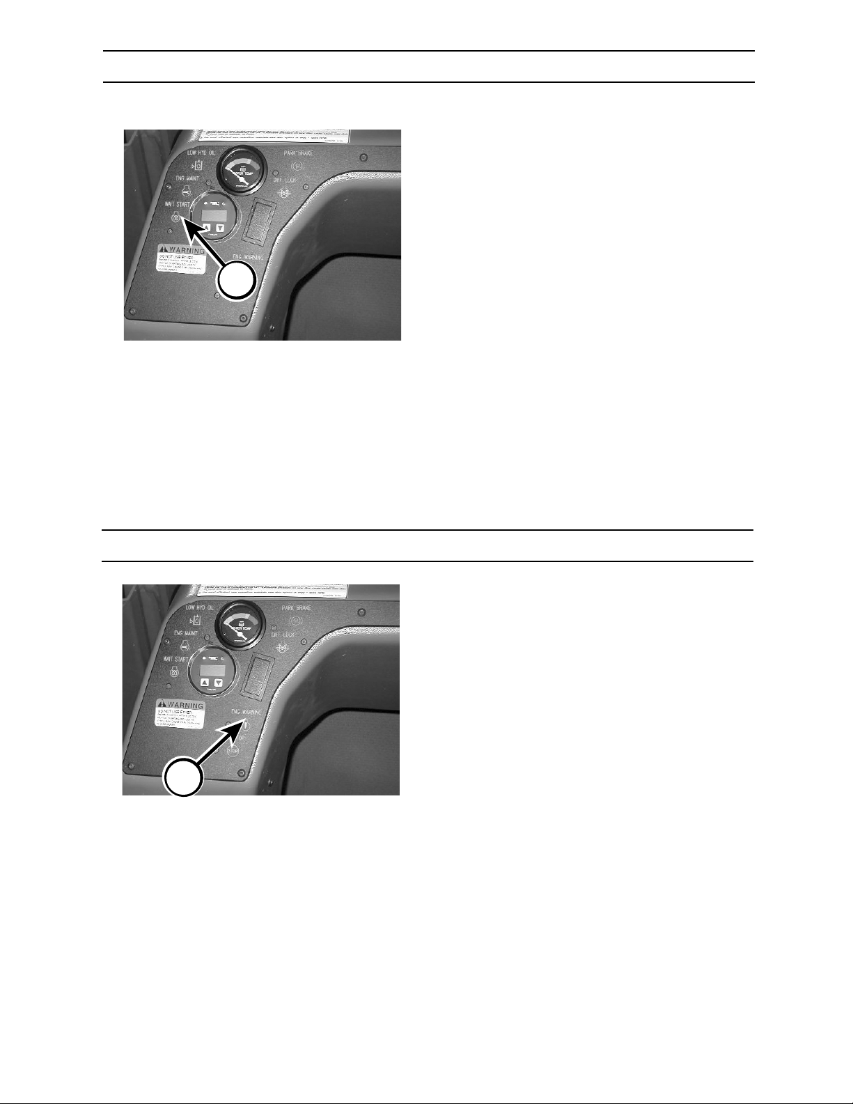
CONTROLS AND INSTRUMENTS
WAIT TO START WARNING INDICATOR
The wait to start warning indicator (A) will light up
when the intake manifold air temperature is too low
for start up.
When the indicator lights, leave key in the ignition
position until indicator light goes out. Then turn the
key to start until engine starts.
A
5/670.276.02
B
ENGINE WARNING INDICATOR
The engine warning indicator (B) will light up when
an error has been sensed by the engine electronic
control module.
When the indicator lights, refer to section 14
Troubleshooting for a complete list of error codes
and causes.
5/670.276.02
2570/2670 0906
4-21
Page 60
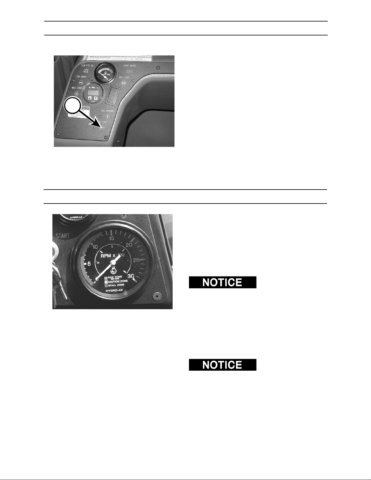
A
CONTROLS AND INSTRUMENTS
ENGINE STOP WARNING INDICATOR
The engine stop warning indicator (A) will light up
when an error has been sensed by the engine
electronic control module.
When the indicator lights, refer to section 14
Troubleshooting for a complete list of error codes
and causes.
5/670.276.02
SAW TACHOMETER
The saw tachometer registers the attachment
motor speed in hundreds of revolutions per minute
(rpm). The saw shaft speed is 1300 rpm.
SAW DISC SPEED ZONES
0 - 700 rpm – saw stall zone
700 - 100 rpm – saw caution zone
1000 - 1300 rpm – saw operating zone
1300 rpm. Operating saw above 1300 rpm will
shorten hydraulic component life.
5/670.024.02
Always rotate saw disc between 1000-1300 rpm at
start of cut. This will ensure that saw disc will not
stall during cut.
Operating saw in the stall zone can cause saw
damage. See Section 6, Operation, for more
details.
with a Quadco® saw disc, refer to Quadco’s
and Operating Guide
and maintenance.
DO NOT run saw above
If your saw is equipped
Safety
for proper saw disc speeds
2570/2670
4-22
0906
Page 61
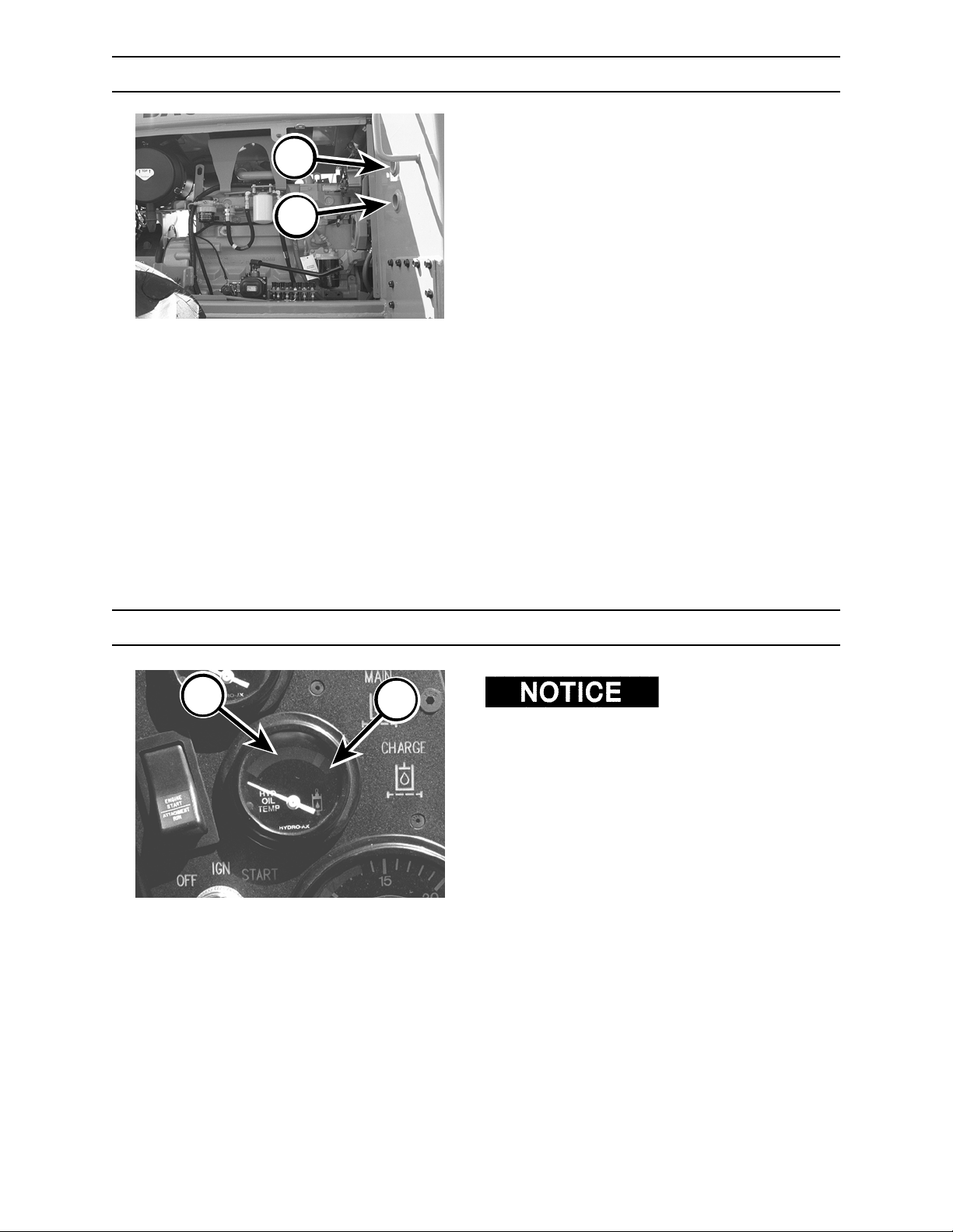
CONTROLS AND INSTRUMENTS
HYDRAULIC OIL RESERVOIR SIGHT GAUGES
The hydraulic oil reservoir has two sight gauges.
A
B
Top gauge (A)–full
Bottom gauge (B)–add
Approximately eleven (11) gallons (41.6 L) of
hydraulic oil is required to raise oil level from
bottom to top gauge.
5/670.025.02
C
HYDRAULIC OIL TEMPERATURE GAUGE
D
hydraulic system damage can occur if operating for
an extended period of time in the yellow zone.
At normal operating temperature, the needle will
point to the green zone (C).
If the needle moves to the red zone (D), shut
engine down immediately and check for plugged oil
cooler.
5/670.026.02
Possible pump or
2570/2670 0906
4-23
Page 62
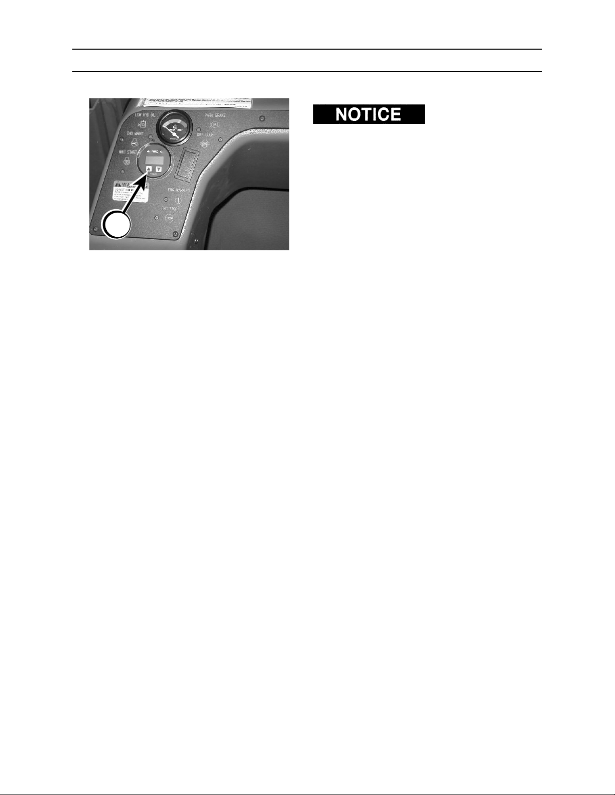
A
CONTROLS AND INSTRUMENTS
MDDM
DO NOT operate engine
if error code has been displayed. Operating with
error can cause system damage.
If error code is displayed on MDDM (A) stop engine
and refer to instructions on following pages.
5/670.276.02
2570/2670
4-24
0906
Page 63
CONTROLS AND INSTRUMENTS
MDDM Operating Instructions
Operating Instructions
The MDDM is simple to use and allows quick and easy naviga-
tion through the menu structure to find the information needed.
The MDDM Main Menu Tree (below) first displays engine data
parameters, followed by the sub-menu entry points.
NOTE:
When first powered up some unused parameters may be
displayed by the MDDM. These parameters will be automatically
removed from the display after the initialization cycle is complete.
Parameters
The following two rules are used for accessing the various items
on the main menus:
1.
To scroll through the parameter list, press either the UP or
Down push buttons.
2.
To select or exit a sub-menu SIMULTANEOUSLY
the UP and DOWN push buttons.
press
Eng Hrs
........ Hrs
Voltage
........ V
Load@RPM
........ %
CoolTmp
........ F
CoolTmp
........ F
OilPress
........PSI
FuelEcon
........GHP
Throttle
........%
ManifTmp
#
LCD Display
Parameters
Continued
Main Menu Tree
NOTE: The parameters displayed on the MDDM will vary
depending on the engine make and model
Keys
Both
Up
Down
Sub-Menus
ServcCode
Press
To
StorCode
Press
Units
Press
E-Config
Press
Srvc
Codes
To
Stor
Codes
To
Units
To
E-Config
From
Srvc
Codes
From
Stor
Codes
From
Units
From
E-Config
2570/2670 0906
4-25
Page 64
CONTROLS AND INSTRUMENTS
MDDM Operating Instructions
Selecting Engine Data Parameters
To read any of the engine parameters press either the UP or DOWN button until the top line of the display shows the desired information.
Selecting Sub-Menus
Press either the UP or DOWN button until the top line of the display
shows the label of the desired Sub-Menu. Then press BOTH the UP and
DOWN buttons SIMULTANEOUSLY
Menu and the next screen on the display will list the Sub-Menu items.
. This action will select the Sub-
Changing Units of Measure
The MDDM can display engine data in either English or Metric units.
continued
To select English or Metric, the Units Sub-Menu must be selected.
To select the Units Sub-Menu, press the UP or DOWN button until the
display shows the following label:
Units
Press
Press BOTH
the Units Sub-Menu. The Units Sub-Menu Figure (below) shows the steps
for selecting the desired units of measure. Two options are available:
1. Press BOTH buttons to retain the current units designation.
2. Press either UP or DOWN button to toggle the units selection, then
the UP and DOWN buttons SIMULTANEOUSLY
press BOTH
buttons to select the desired unit of measure.
to select
Line 1 shows the
current units
designation M=Metric,
E=English
Line 2 shows the
current units
designation, full text
Line 1 shows the
current units
designation M=Metric,
E=English
Line 2 shows the
alternate units
selection
Line 1 shows the
current units
designation M=Metric,
E=English
Line 2 shows the
alternate units
selection
Enter
Units
Units: E
-English
Units: E
New: Met
Units: E
New: Eng
Current Units Screen,
displays the current units
designation.
Units Sub Menu
New Units
-English
Press BOTH keys to select
current units and exit sub menu.
New Units
-Metric
New Units
-English
Exit
Units
Exit
Units
Exit
Units
2570/2670
4-26
0906
Page 65
CONTROLS AND INSTRUMENTS
MDDM Operating Instructions
continued
Viewing Engine Configuration Data
The MDDM can display the engine configuration data stored in
the engine ECM. To select the Engine Configuration Sub-Menu
(shown below), press the UP or DOWN button until the display
shows the following label.
E-Config
Press
NOTE: The parameters displayed on the MDDM will vary
depending on the engine make and model
Enter
E-Config
Speed 1
.........RPM
Torque 1
.........%
Speed 2
.........RPM
Torque 5
.........%
Speed 6
.........RPM
Gov Gain
.........%
Press BOTH
select the Engine Configuration Sub-Menu. The MDDM will
display the engine configuration data as shown in Engine
Configuration Sub-Menu. If the Engine Configuration is not
available, the display will show:
the UP and DOWN buttons SIMULTANEOUSLY to
E-Config
N/A
Engine Configuration
Sub-Menu
Hi Limit
.........%
Configuration
Data Continued
Torque 2
.........%
Speed 3
.........RPM
Torque 3
.........%
Speed 4
.........RPM
Torque 4
.........%
Speed 5
.........RPM
Ref Torq
.........f/#
Speed 7
.........RPM
Time Limt
.........sec
Lo Limit
.........RPM
Hi Limit
.........RPM
Lo Limit
.........%
To exit the E-Config
Display sub menu:
Press BOTH keys at
ANY time.
2570/2670 0906
4-27
Page 66
CONTROLS AND INSTRUMENTS
MDDM Operating Instructions
continued
Viewing Active Engine Service Codes
The MDDM continuously monitors all messages broadcast over the
SAE J1939 Control Area Network (CAN) and displays all Active
Service Codes at the time the message is broadcast. When a fault
occurs the display will show the message "SrvcCode" every five
seconds interrupting the currently displayed parameter. In addition,
the amber LED will be illuminated during Active Service Code
warning faults, and the red LED will be illuminated during shutdown faults. These warnings will continue until the fault clears.
To view the Active Service Codes select the Service Code SubMenu by pressing the UP or DOWN button until the display
shows the following label:
SrvcCode
Press
Enter
SrvcCodes
SPN...........
FMI............
Press both the UP and DOWN buttons SIMULTANEOUSLY to
select the Service Code Sub-Menu. The MDDM will display all
Active Service Codes as shown in the Service Codes Menu
schematic (below). If Service Codes are not available, the display will show the following:
SrvcCode
No Codes
Service Codes Sub-Menu
Data Available
First SPN, FMI
combination
User may exit the
Service Code
Display routine by
pressing BOTH
keys Simultaneously
at any time.
SPN...........
Exit
SrvcCodes
FMI............
SPN...........n
FMI............n
Last SPN, FMI
combination (n)
Explanation of SPN & FMI Diagnostic Codes
SPN refers to Suspect Parameter Number and FMI refers to Failure Mode Identifier.
Both the SPN and FMI are used in the J1939 standard for identification of faults and conditions.
2570/2670
4-28
0906
Page 67
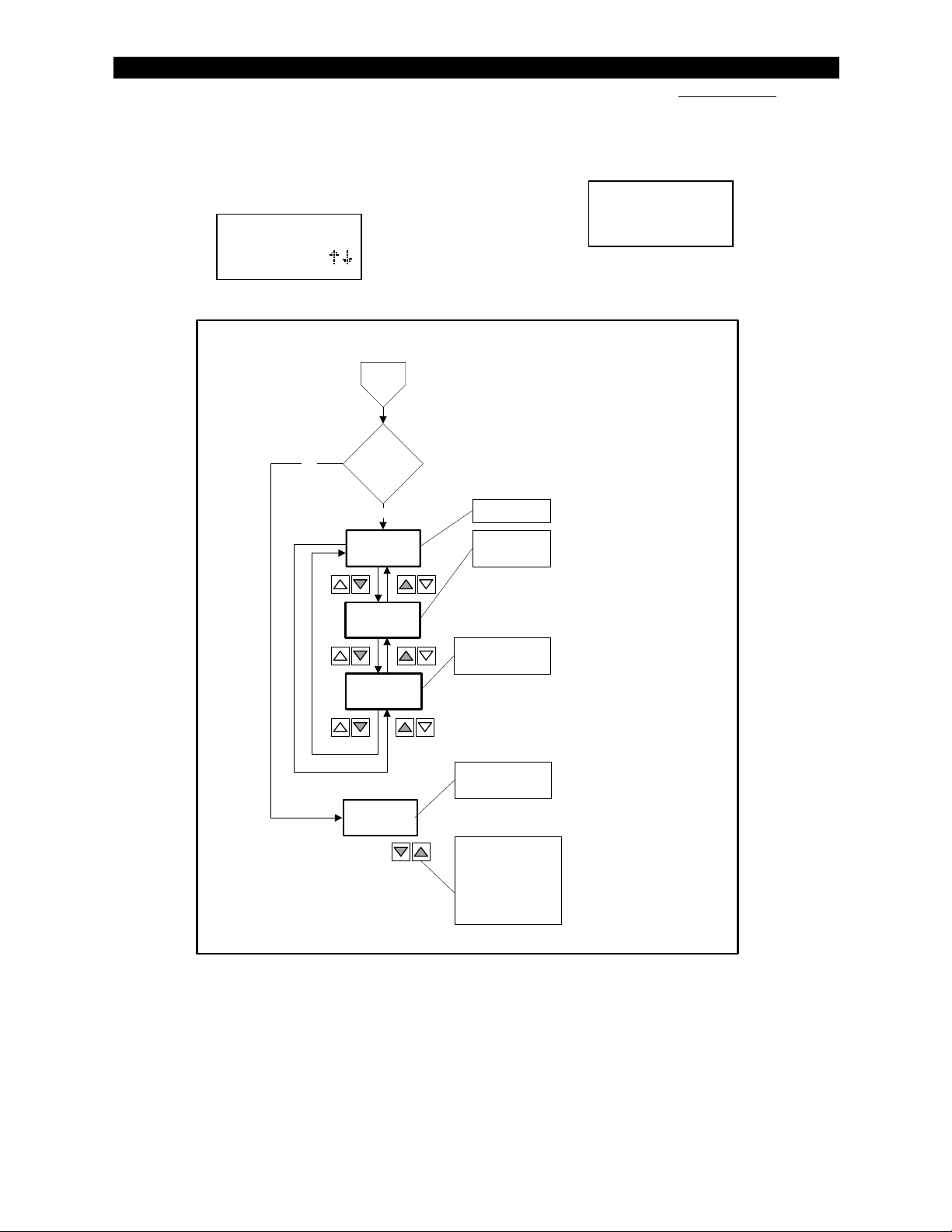
CONTROLS AND INSTRUMENTS
MDDM Operating Instructions
Viewing Service Codes in
The Engine Control Module (ECM)
The MDDM can request Stored Service Codes (DM2) from the
engine. The Stored Service Codes may be used for diagnostic
and service needs. To view the Stored Service Codes it is necessary to select the StorCode Sub-Menu by pressing the UP or
DOWN button until the display shows the following label.
continued
Press both the UP and DOWN buttons SIMULTANEOUSLY
select the StorCodes Sub-Menu. The MDDM will display the
Stored Service Codes according to the menus shown in the
schematic below.
If Stored Service Codes are not available, the display will show:
to
StorCode
StorCode
Press
No
Enter
StorCode
if
DM2 data is
available
Yes
LampStat
0x..
SPN.........i
FMI..........i
SPN.........n
FMI..........n
No Data
Stored Codes
(Previously Active Codes)
Sub-Menu
Lamp Status
First SPN, FMI
combination
Last SPN, FMI
combination (n)
Indication of NO
DM2 Data.
StorCode
No Data
User may exit the
Service Code
Display routine by
pressing BOTH
keys Simultaneously
at any time.
2570/2670 0906
4-29
Page 68
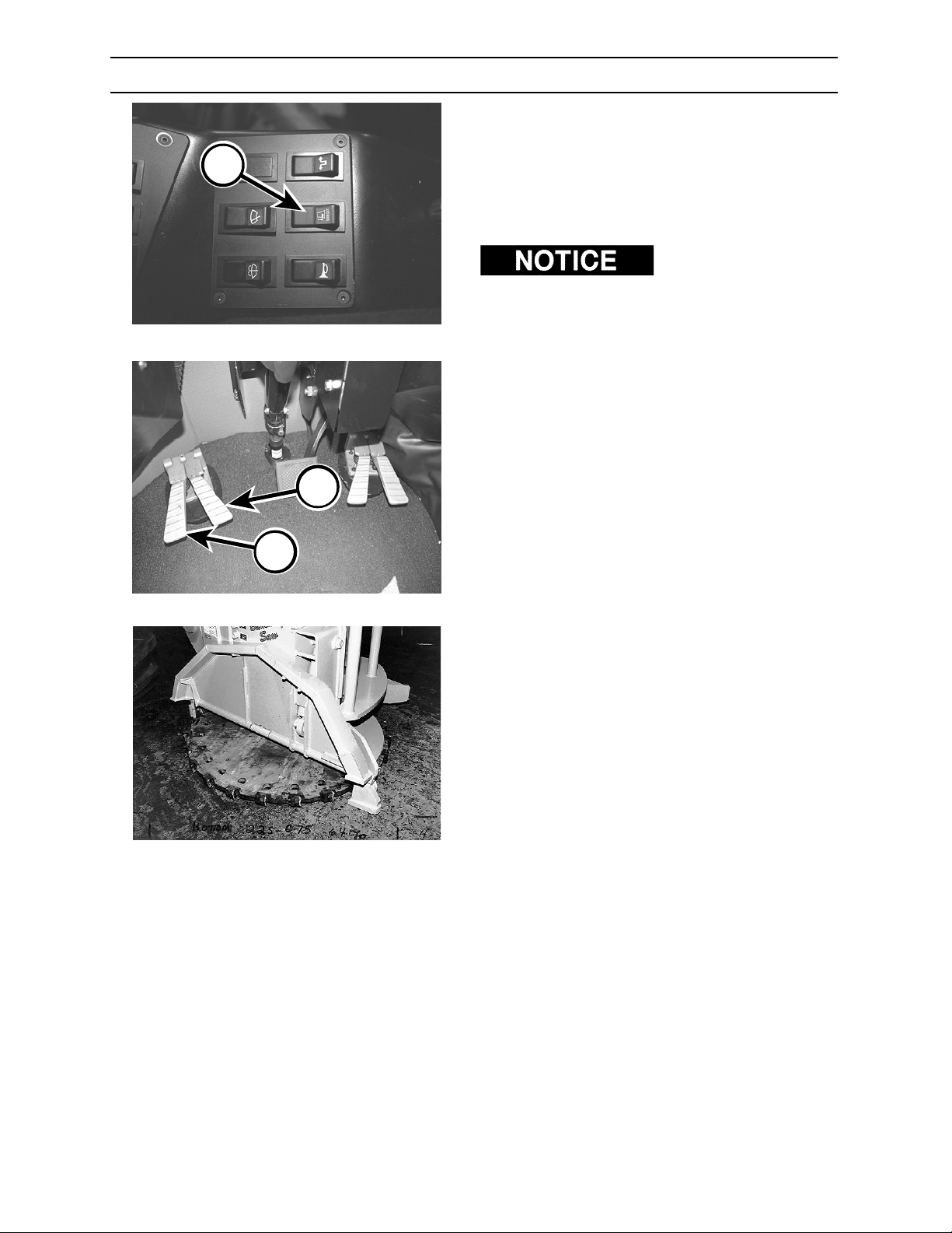
CONTROLS AND INSTRUMENTS
SIDECUT SWITCH (22SC BUNCHING SAW ONLY)
To raise guard for directional felling or side cutting:
1. Close bunching arm.
D
E
F
5/670.005.02
5/670.003.02
2. Hold sidecut switch (D) in the depressed
position while closing gather arm with control
pedal (F). Guard will raise as gathering arm
starts to fully close.
Be sure to raise guard
completely. If guard is not completely raised,
damage will occur to guard and guard hydraulics
while performing directional felling.
Swing-up guard will automatically lower when
gathering arm is opened with control pedal (E) and
when sidecut switch is not depressed.
2570/2670
5/670.015.02
4-30
0906
0203
Page 69
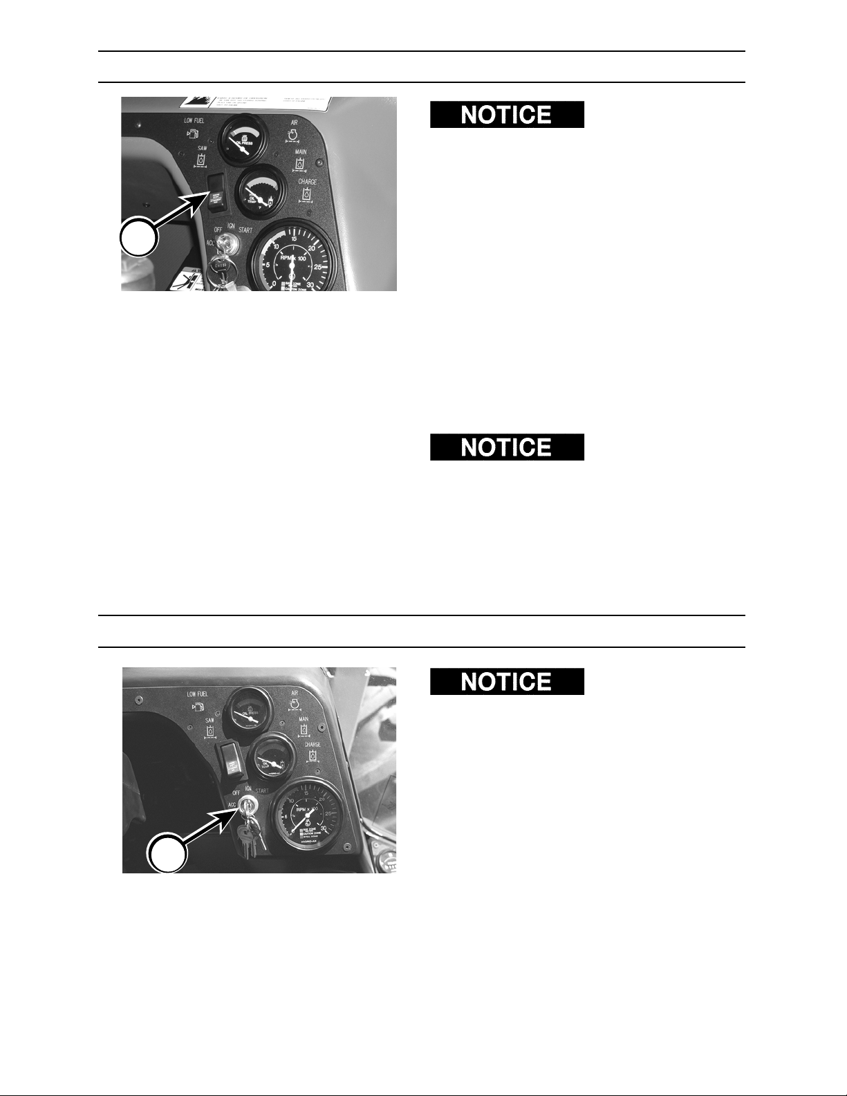
A
CONTROLS AND INSTRUMENTS
ENGINE START - ATTACHMENT ON/OFF SWITCH
Cab door must be
closed, Parking brake must be disengaged, and
attachment on/off switch must be in ENGINE
START position before engine will start.
The engine start - attachment on/off switch (A)
must be in ENGINE START position (depress top
of switch) before starting machine. Machine will
not start if on/off switch is in the ATTACHMENT
RUN position.
SAW
To rotate saw disc, depress switch down to
ATTACHMENT RUN position while engine is at half
to full throttle.
SHEAR
To activate, depress switch down to ATTACHMENT
RUN position.
B
operate slowly, check to be sure attachment on/off
switch is in ATTACHMENT RUN position.
IGNITION SWITCH
set and attachment on/off switch must be in
ATTACHMENT RUN position before engine will
start.
Turn key in ignition switch (B) clockwise (CW) to
start machine. Release key when engine starts.
Turn key OFF to shut engine down.
When key is in ACC position, electrical components
have power.
5/670.005.02
When leaving machine, be sure ignition switch is in
OFF position, and remove key. Doing so will
prevent drain on battery.
If shear appears to
Parking brake must be
2570/2670 0906
4-31
Page 70
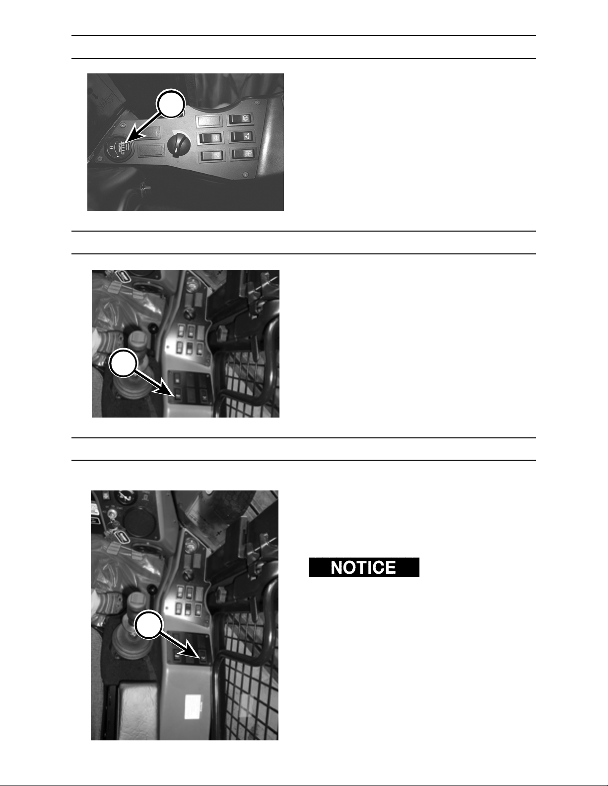
A
CONTROLS AND INSTRUMENTS
HOURMETER
The hourmeter (A) registers in full hours and tenths
of hours.
5/670.007.02
HORN SWITCH
Press horn switch (B) to sound horn.
B
92603.05
OVERRIDE SWITCH
If the parking brake switch interlock and/or door
switch interlock fail, hold the override switch (A) to
steer machine (joystick steering models only),
propel machine, and to operate bunching and
gathering arms.
When holding down
override switch, attachment pump will be disabled
resulting in no saw disc rotation or shear function.
A
2570/2670
92603.05
4-32
0906
Page 71
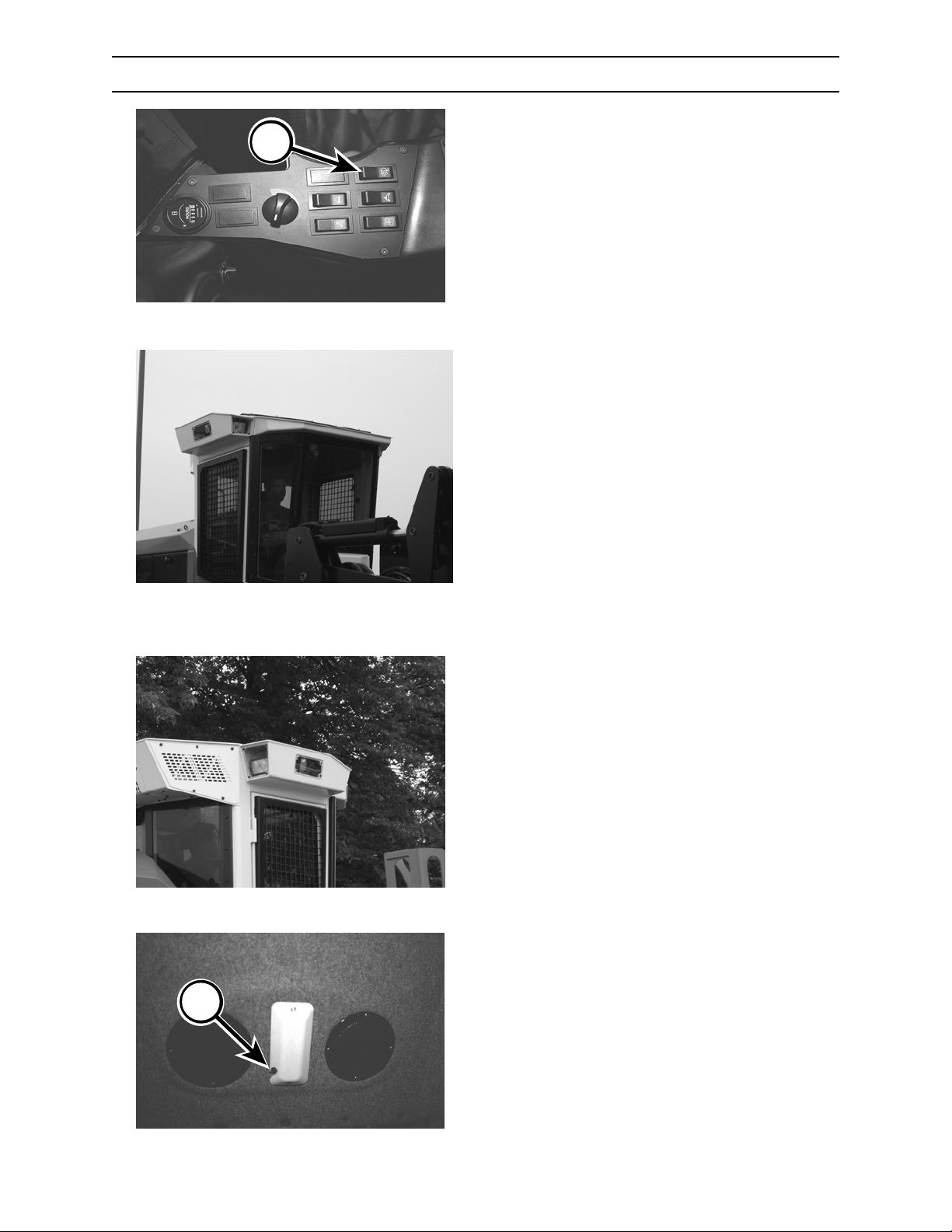
CONTROLS AND INSTRUMENTS
LIGHTS
OPERATING LIGHTS
A
Depress switch (A) to turn operating lights to
desired setting:
Top position — lights off
Middle position — two front lights on
Bottom position — two front lights, two side
lights, and two rear lights on.
5/670.007.02
Front and side flood lights.
B
Rear flood lights.
DOME LIGHT
Depress switch (B) to turn dome light on or off.
5/670.031.02
2570/2670 0906
4-33
Page 72
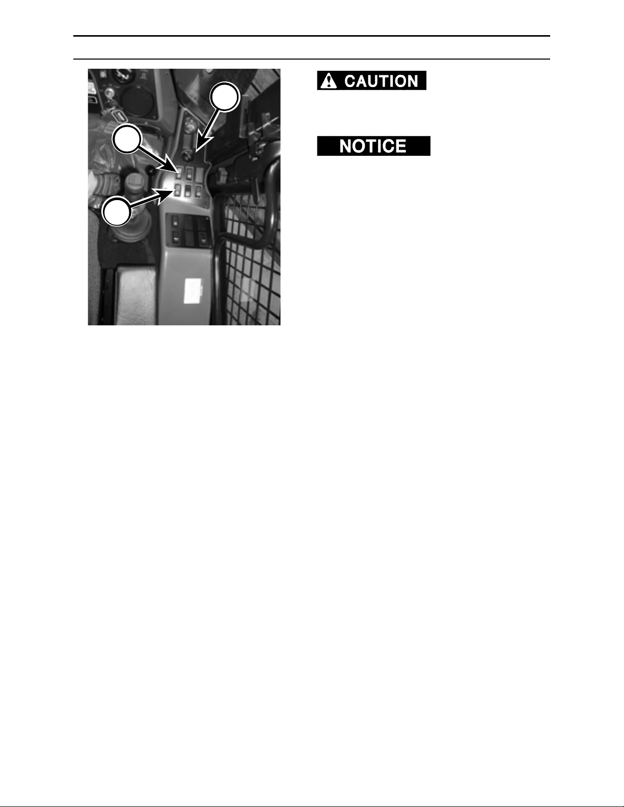
CONTROLS AND INSTRUMENTS
AIR CONDITIONING / HEATER CONTROLS
Your air conditioner
C
contains R-134A refrigerant. Avoid breathing
refrigerant and lubricant vapor or mist.
Exposure may irritate eyes, nose, and throat.
B
A
92603.05
Start and run engine for
two (2) minutes before starting air conditioner.
Depress the A/C-heater switch (A) to desired
setting:
Top position — heater
Middle position — off
Bottom position — air conditioner
Turn the fan switch (B) to desired fan setting:
Top position — low speed
Middle position — medium speed
Bottom position — high speed
Use temperature control (C) on unit in cab to
regulate temperature of the air conditioner.
Temperature control must be ON before
compressor will engage. Turn control clockwise
(CW) for warmer air, and counterclockwise (CCW)
for cooler air.
Move louvers to adjust direction of air flow.
2570/2670
4-34
0906
Page 73
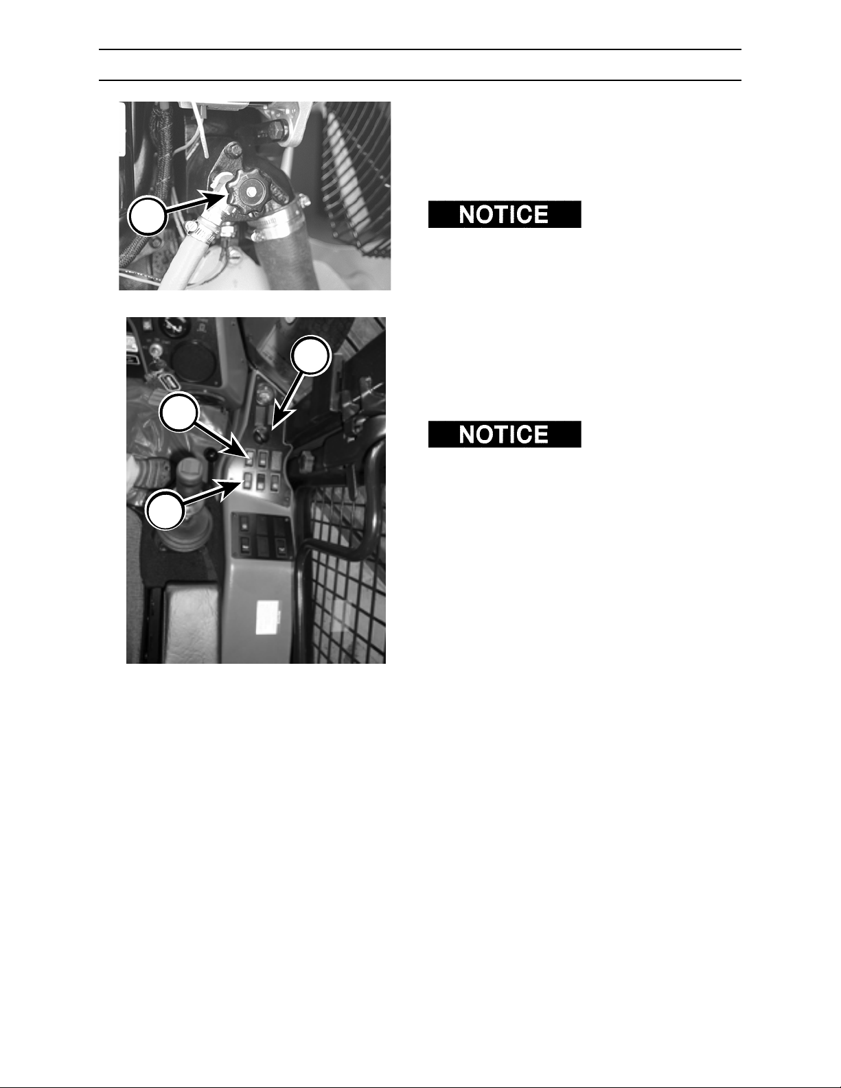
CONTROLS AND INSTRUMENTS
CAB HEATER TEMPERATURE CONTROL
1. With engine OFF and parking brake set, turn
heater coolant valve (A) clockwise (CW) to
close valve.
2. Open heater valve one-quarter (1/4) turn
counter clockwise (CCW).
A
B
A
C
5/670.032.02
Heater coolant valve may
require periodic adjustment depending on ambient
(outdoor air) temperature.
3. Start engine. Depress heater switch (B) and
fan switch (C) to test heat adjustment.
4. To make further adjustments to cab
temperature, turn engine OFF, set parking
brake, and turn heater coolant valve clockwise
(CW) for cooler cab temperature, or
counterclockwise (CCW) to stop convection
heating inside cab.
In warm weather, it may
be necessary to close both heater coolant valves (if
equipped - the other heater valve is located on right
side of engine) to stop convection heating inside
cab.
92603.05
2570/2670 0906
4-35
Page 74
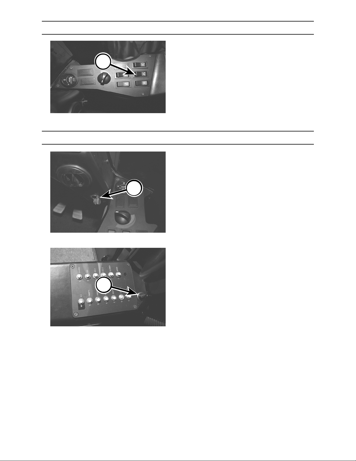
A
CONTROLS AND INSTRUMENTS
AUTO-SHIFT SWITCH
The auto-shift range selection allows transmission
to shift between high and low gear under different
power situations.
Depress the bottom of switch (A) to select autoshift range.
Low range maintains hydrostatic transmission in
low range.
Depress top of switch (A) to select low range.
5/670.007.02
Shifting between auto shift and low range can be
done “on the fly.”
POWER OUTLETS
Two 12-volt power outlets are provided for
electrically powered accessories. To protect battery
against accidental discharge, outlets provide power
only when key switch is in ON or ACC position.
D
5/670.033.02
2570/2670
E
5/670.034.02
4-36
0906
Page 75
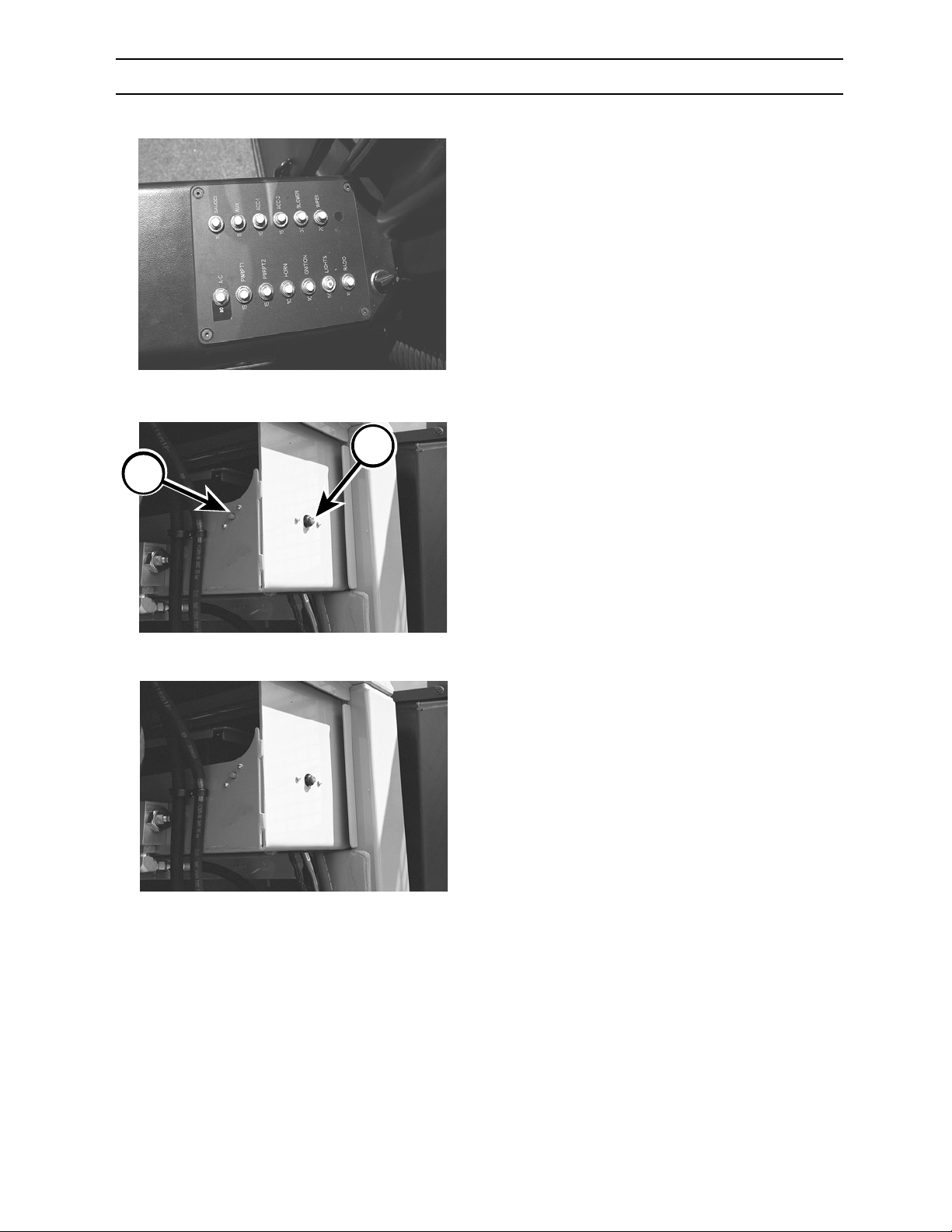
CONTROLS AND INSTRUMENTS
CIRCUIT BREAKERS
Circuit breakers protect electrical circuits from
current overload.
If an overload should occur, circuit breaker will trip,
breaking the flow of current, and preventing
damage to the circuit.
To reset circuit breaker, depress tripped circuit .
Circuit Breakers
A
B
Electrical System Circuit Breakers
5/670.034.02
The main electrical system circuit breaker (A) (150
amp) is located inside the right front side screen,
on the battery box. The starter solenoid relay (B)
(20 amp) is also located here.
5/670.272.02
There are two breakers located in line of the engine
electrical harness.
5/670.272.02
Electrical System Circuit Breakers
2570/2670 0906
4-37
Page 76
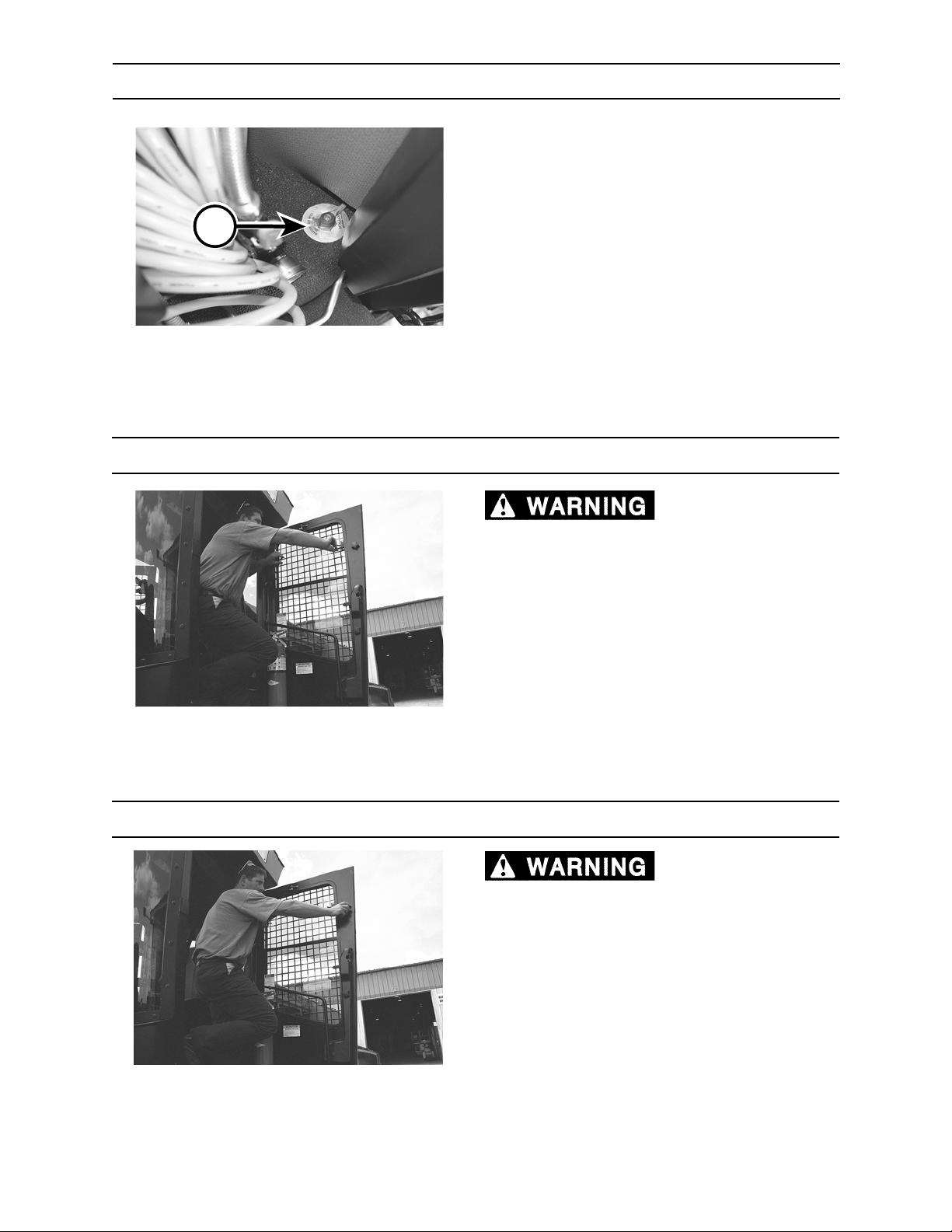
CONTROLS AND INSTRUMENTS
BATTERY DISCONNECT MASTER SWITCH
When activated, the battery disconnect master
switch (D), located behind the operator’s seat
• prevents accidental engine start up when
servicing machine,
D
• prevents accidental battery drain; and,
• helps serve as a vandal deterrent.
Turn switch OFF to shut off or disconnect electrical
system.
5/670.036.02
Turn switch ON to connect electrical system.
All systems will shut down when battery disconnect
master switch is turned OFF.
SLIDING WINDOW
sliding windows without guarding in place can
cause severe injury or death. Never operate
machine without window guarding locked in
place.
Depress window latches to move window to
desired opening.
Debris coming through
5/670.037.02
EMERGENCY WINDOW EXIT (RH & LH)
Debris coming through
sliding windows without guarding in place can
cause severe injury or death. Never operate
machine without window guarding locked in
place.
USING WINDOW EXIT
1. Loosen window knobs until guard falls out.
2. Push on window until window falls out.
5/670.038.02
2570/2670
4-38
0906
Page 77
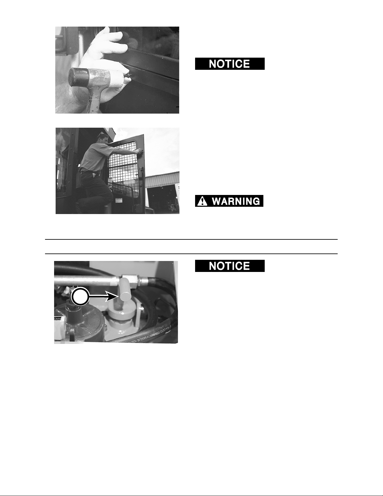
CONTROLS AND INSTRUMENTS
REPLACING EMERGENCY EXIT WINDOW
1. With window guarding removed, place sliding
window frame into door frame.
to door frame, use ONLY plastic break-away clips.
Using anything other than plastic clips (available
from your Blount dealer) will prevent a quick
emergency exit.
2. Align holes on door and window frames.
5/670.042.02
3. Secure window and door frames together by
placing a clip into aligned frame holes. Lightly
tape clip with a hammer until head of clip is
against window frame.
4. Repeat Step 3 for remaining three (3) holes to
properly secure sliding window frame to door
frame.
5. Replace window guarding by tightening
window knobs until frame is firmly in place.
When securing window
5/670.038.02
SHUT-OFF MANIFOLD VALVE
A
Shut-off Manifold Valve Open
9305.06
Debris coming through
sliding windows without guarding in place can
cause severe injury or death. Never operate
machine without window guarding locked in
place.
DO NOT turn shut-off
manifold valve to the CLOSED position while
engine is running. Serious damage to the hydraulic
system will result if oil flow is stopped.
The shut-off manifold valve has two functions:
1. When valve is in the CLOSED position, engine
cannot be started.
2. Valve is used to shut off oil flow from hydraulic
reservoir. This allows operator or mechanic to
change a hose or make hydraulic repairs
without draining the hydraulic reservoir.
Shut-off manifold valve must be fully turned to
either OPEN or CLOSED position for proper
operation.
2570/2670 0906
4-39
Page 78
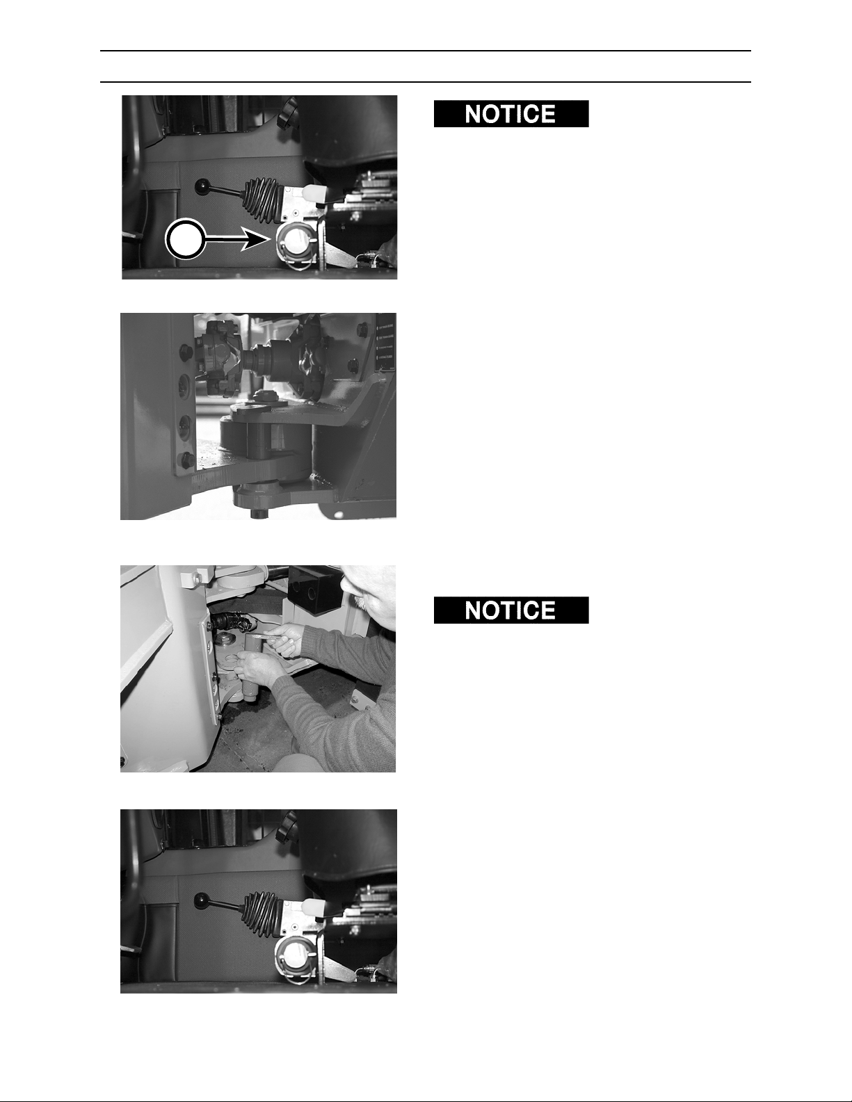
A
Step 1
CONTROLS AND INSTRUMENTS
ARTICULATION LOCK
before performing service or maintenance around
the center hinge area or on the front frame and
attachment.
INSTALLING LOCK
1. Remove articulation pin from storage location.
2. Place pin through hole in rear frame.
3. Mount cab and start engine.
9237.06
4. SLOWLY steer machine until pin slides
completely down into front frame hole and
bottom rear frame hole.
5. Secure articulation pin with locking pin.
Install articulation pin
Step 2
Step 1
5/670.046.02
REMOVING LOCK
Be sure to place
articulation pin in storage location before propelling
machine.
1. Remove locking pin from articulation pin.
2. Remove articulation pin from frame and place
in storage location in front of the operator seat.
Secure with locking pin.
5/670.047.02
2570/2670
Step 2
4-40
0906
Page 79
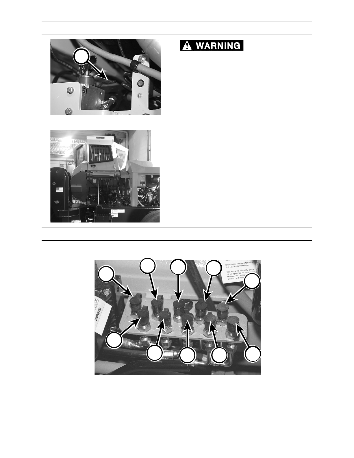
A
CONTROLS AND INSTRUMENTS
CAB TILT CONTROL
tilted cab unless cab is completely tilted in its
over-center position. If a hydraulic hose or
component failure occurs, cab could
accidentally lower unexpectedly and cause
serious personal injury.
Move hydraulic pump control lever (A) to raise or
lower cab.
For proper cab tilt procedures, see Section 6,
9270.06
Operation.
NEVER get under a
HYDRAULIC DIAGNOSTIC CENTER (PRESSURE TEST PORTS)
The hydraulic diagnostic center (pressure test ports) provides easy access to hydraulic system pressure
test ports. It is located inside the left front side screen.
B
C
D
A
E
F
A. B Port Propel Pump
B. A Port Propel Pump
C. B Port Propel Motor
D. A Port Propel Motor
E. Charge Pressure
G
H
F. Pilot Pressure (DIF Manifold)
G. Not Applicable
H. Lift/Tilt Pressure
I. Not Applicable
J. Saw Pump Pressure
I
J
5/670.050.02
2570/2670 0906
4-41
Page 80
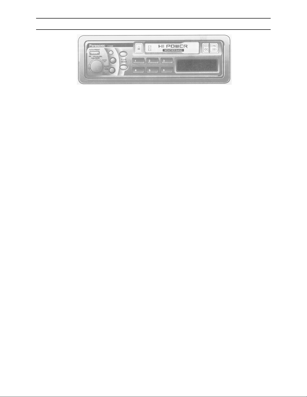
CONTROLS AND INSTRUMENTS
AM/FM STEREO CASSETTE RADIO
G.043.02
POWER
Turn ignition key ON. Turn knob (A) clockwise to switch power
on. When power is turned off, clock will show on display.
VOLUME
Turn knob (A) clockwise to increase volume and
counterclockwise to decrease volume.
BALANCE
Keep pulling knob (A) and turn it left or right to shift sound to left
or right speakers.
BASS AND TREBLE
Bass Control: Turn knob (B) to adjust bass response.
Treble Control: Pull and lock knob (B) and turn to adjust treble
response. After adjusting, press knob in.
SELECTING A BAND
Press BAND (C) to select bands in the following order: FM1–
FM2–AM–WB (Weather Band)
Note:
• Band cannot be changed to radio mode while playing a tape .
If you want to change radio mode, eject tape.
• “ST” indicator will light when a station is broadcasting in
stereo.
MANUAL TUNING
Press (D) or (E) to move to a higher or lower frequency.
SEEK TUNING
Press and hold (D) or (E) for more than a half second, then
release. Radio automatically stops on next station.
SCAN TUNING
Press knob (A) to scan next stations (sequentially upward) for
about five (5) seconds . Press knob again to cancel.
TO REDUCE INTERFERENCE DURING FM BROADCASTS
Press MONO/ST (F) for monaural reception in case a lot of
interference is present in an FM stereo signal or to improve
listening quality of weak FM broadcasts.
MANUAL STATION PRESET
Press (C) to select desired band. Use
find a station you wish to program into memory. Press and hold
a station selector button (G) until display blinks. Memory is now
set for that button on the band you have selected. Repeat
process to set other stations for FM1 to AM bands. Note: You
can change memory settings by repeating the above procedure.
TUNING IN A PRESET STATION
Press any of the buttons (G) to tune in astation preset by the
above manual station preset procedure.
manual
or
seek
tuning to
AUTO STATION PRESET
Select a band and press and hold BAND (C) for more than two
(2) seconds:
• The six (6) strongest available stations will be automatically set
in memory on preset buttons (G).
• Once set, the preset stations are sequentially scanned for five
(5) seconds.
• Press appropriate preset button for the station you want to
hear.
LOADING A CASSETTE
Gently insert cassette with exposed tape facing right until
mechanism captures it and playback begins.
• When program indicator ▲ or ▼ lights, press (H) to rewind or
press (I) to fast-forward tape.
CHANGING SIDES
Firmly press (H) and (I) simultaneously to switch to the other
side of the tape. Display will change to indicate which side is
playing.
STOPPING AND EJECTING THE TAPE
Once inserted into cassette player, your tape will play
continuously until you eject it. If you press (J), unit ejects the
tape and returns to radio operation. When you shut down the
engine, tape will stop but not eject.
CASSETTE CARE AND MAINTENANCE
• Always check that the tape is tightly wound inside take-up
spool on cassette. If the tape is loose, wind it with a six-sided
pencil.
• To maintain your cassette player in top condition, avoid using
tapes longer than ninety (90) minutes (C-90).
• Never insert a cassette into your player when cab temperature
is near or below freezing.
CLOCK
Press (K); “ADJ” is displayed. Press and hold (K) again for more
than two (2) seconds. “12” blinks indicating time setting mode is
activated.
To set hours, press (D) or (E).
Press (K) again for minute setting.
To set minutes, press (D) or (E). Hold (D) or (E) to change
numbers rapidly.
When you have set the time, press (K).
RESETTING THE TIME
When you want to reset the time, press and hold (K) for more
than two (2) seconds to activate the time setting mode. Then
repeat CLOCK procedure.
SELECTING THE CLOCK DISPLAY
Press (K) repeatedly to switch display between each listening
mode (radio, tape) and clock.
2570/2670
4-42
0906
Page 81
PRE-START INSPECTION
PRE-START INSPECTION
Do not use this machine until you read, study, and understand this
manual, and learn how to properly operate this machine. Operating this machine without reading,
studying, and understanding this manual could result in severe personal injury or death.
Failure to perform a daily inspection of the machine could result in
machine damage and severe personal injury.
Inspector’s Initials Machine Serial NumberDate of Inspection
PRE-START CHECKS: ON THE GROUND
Check fuel level; add fuel if necessary.
Check engine oil level. Add engine oil if necessary.
Check radiator coolant level. Add proper coolant mixture if necessary. Clean radiator of debris.
Check air cleaner. Clean or replace air cleaner/filter if necessary.
Check for protective clothing (wear it) and safety equipment (know where it is).
Check entire machine by performing a thorough walk-around inspection.
Check for loose or missing parts. Tighten loose parts. Replace any missing parts.
Check hydraulic hoses and lines for wear and/or damage. Replace any defective hoses and/or lines.
Check that machine has been properly lubricated as spelled out in the Scheduled/Periodic Maintenance
Services section of this manual.
Check shields and guards. They must be in place and undamaged.
Check that safety decals are on machine and that they are readable.
Check that shut-off valves are open.
Check for dirt and grime on all hydraulic components. Clean away dirt and grime to help prevent
overheating.
Check for ice, snow, oil, and grease on steps and walkways. Clear away ice, snow, oil, and grease to
prevent slips and falls.
Check for any loose skid-resistant mats. Replace mats if they are loose.
Check hydraulic oil reservoir level. Add hydraulic oil to reservoir if necessary.
Check for combustible or flammable materials. Remove them from machine if you find them.
Check mounting hardware for tightness.
Check that machine will not be near electrical wires. See Section 6, Operation, for more information.
Check saw teeth for sharpness and mounting torque. Tighten any loose hardware. Repair or replace any
saw teeth if they are damaged.
Check shear blades for sharpness, alignment, or damage. Tighten loose hardware. Repair or replace
blades if damaged.
Check belly covers for combustible or flammable materials. Remove such materials if you find any.
Check that locking cap screws on cab tilt latch pins are secure.
Check front and rear frames for damage, cracks, debris, and other problems. Immediately report any
structural problems (cracks) to an authorized dealer for diagnosis and repair or replacement.
Check tires for wear and/or damage. Also check tire pressure.
Check electrical system for worn or frayed wires and loose connections. Repair or replace if necessary.
Check that all lights are in working order.
You can copy the pages in this section. Check off each inspection
item before operating machine. File the copy as a record of
inspection as required by OSHA.
2570/2670 0906
5-1
Page 82
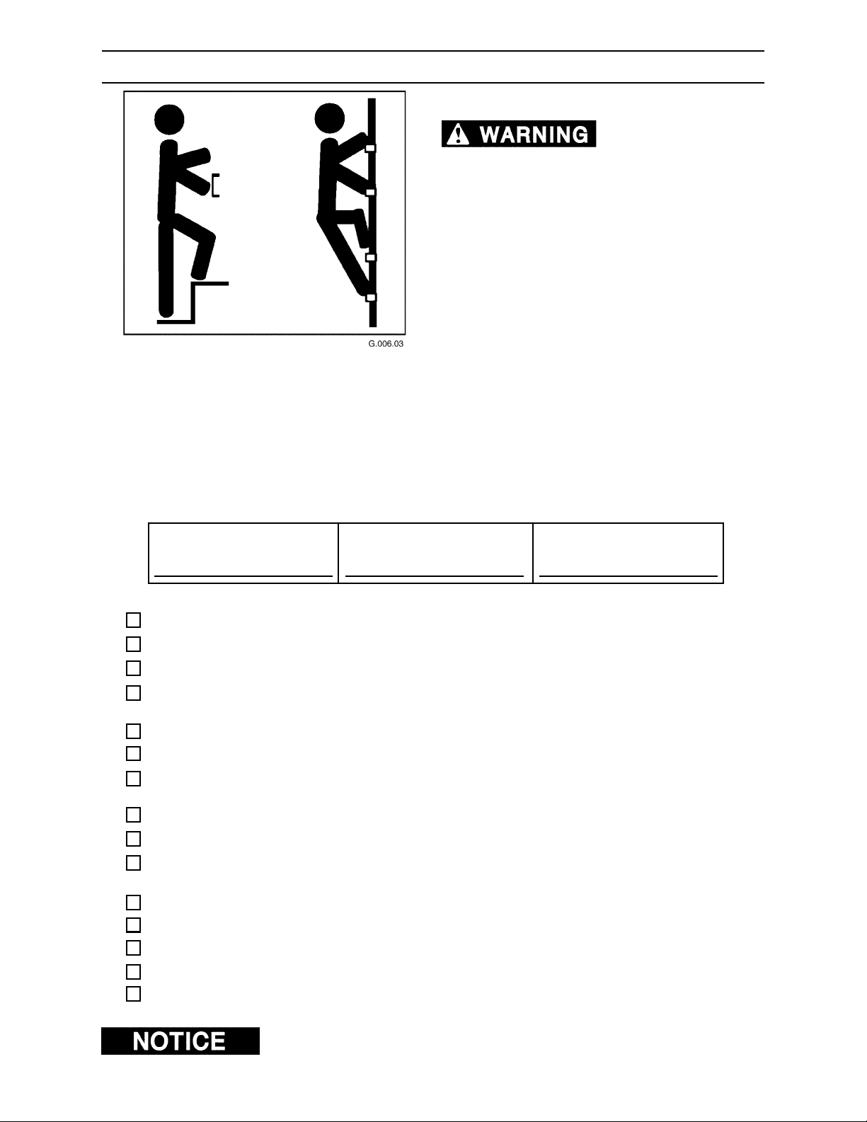
PRE-START INSPECTION
PRE-START CHECKS: IN THE CAB
HANDHOLD AND STEPS
cause severe personal injury or death.
Use provided handholds and steps while
maintaining at least 3 points of support (1 foot and
2 hands or 2 feet and 1 hand) when getting on and
off machine. Face machine when getting on and
off it.
Never use controls as handholds.
DO NOT mount machine if hand rails or steps are
broken or missing. Get them repaired first.
DO NOT jump on or off machine unless it has
touched a live electrical wire and must be exited.
Ensure firm foot position when getting on and off
machine. Be careful of slippery conditions on
platform, steps, and handholds when getting on
and off machine.
Slips and falls can
To prevent slips and falls, replace skid-resistant
material if it is damaged, worn or missing.
Inspector’s Initials
Check that there is no mud or debris on cab floor.
Check for free movement of controls.
Check that safety decals are present and can be clearly read.
Check that all cab polycarbonate windows are clean and clear. Replace any damaged polycarbonate
material.
Check that seat belt works properly. Replace worn or damaged seat belt.
Check that fire extinguisher is adequately charged.
Check instrument panel for broken gauges and/or broken indicator lights. Have gauges and/or indicator
lights repaired if necessary.
Check fuel gauge to be sure machine has enough fuel. Refuel machine if necessary.
Check window emergency exits. All emergency exit knobs should be present and turn freely.
Check ROPS (Rolling Object Protective Structure) and/or FOPS (Falling Object Protective Structure) for
damage. See an authorized dealer if damaged.
Check that all items in cab that are not part of the machine, such as lunch boxes or tools, are secured.
Check that parking brake is set.
Place engine/start—attachment run switch to ENGINE START position.
Check that the pressurized water system is fully charged at 65 psi (438 kPa).
Check that the MDDM does not have an error code.
Machine Serial NumberDate of Inspection
2570/2670
You can copy the pages in this section. Check off each inspection
item before operating machine. File the copy as a record of
inspection as required by OSHA.
5-2
0906
Page 83
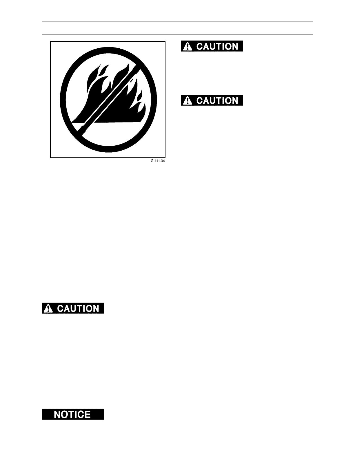
PRE-START INSPECTION
FIRE PREVENTION
Fires can cause
personal injury or machine damage.
Keep machine clean. Remove debris, especially
from heat sources. Fire prevention beats fire
fighting. Hourly or daily inspections can reduce the
possibility of fires.
Forest debris can collect
on the machine and cause a fire. When forest
debris mixes with flammable fluids in a hot,
confined space, the risk of a fire starting greatly
increases. KEEP THE MACHINE CLEAN.
Check machine daily for fire hazards. Remove debris from areas of the machine that create heat and that
are potential fire start points. Depending on your machine model, check for flammable debris in the
following locations:
• Engine block • Turbocharger
• Exhaust manifold • Battery
• Electrical connections • Control valves
Fire needs fuel. Remove combustible material (fuel for fire) from heat sources. Keep the machine clean.
Remove the following materials from areas of the machine that create heat:
• Pine needles • Twigs • Debris
• Shop rags • Oil spills • Coolant Mixture
• Leaves • Sticks
• Grease • Bark
• Sawdust • Diesel fuel
Keep the machine clean. Risk of fire increases if combustible materials and
flammable materials build up on machine. This machine was not designed to house or store
combustible materials.
Regularly remove flammable materials (such as diesel fuel, engine oil, hydraulic oil, and grease) from all
areas of the machine. Clean up after working. Keep the fuel and hydraulic systems in good repair.
Check hydraulic hoses, fuel lines, and fittings for leaks. Tighten loose fittings. If hoses or lines are bent,
kinked, or show signs of wear, install new parts. Check electrical connections to be sure they are clean
and secure.
Frayed or worn insulation on battery cables or other wires may lead to electrical fires. Check cables and
wires and replace if insulation is frayed, worn, or damaged.
Keep water tank pressurized. Check hose for damage; replace if necessary. Make sure hose and valves
are clear of rust or sediment and water can flow freely.
At the end of each shift ALWAYS stay with the machine for 30 minutes after
shutting down the engine to ensure there is no forest debris/trash fire start up. Keep a fire extinguisher
ready during this 30 minute cool down.
2570/2670 0906
5-3
Page 84
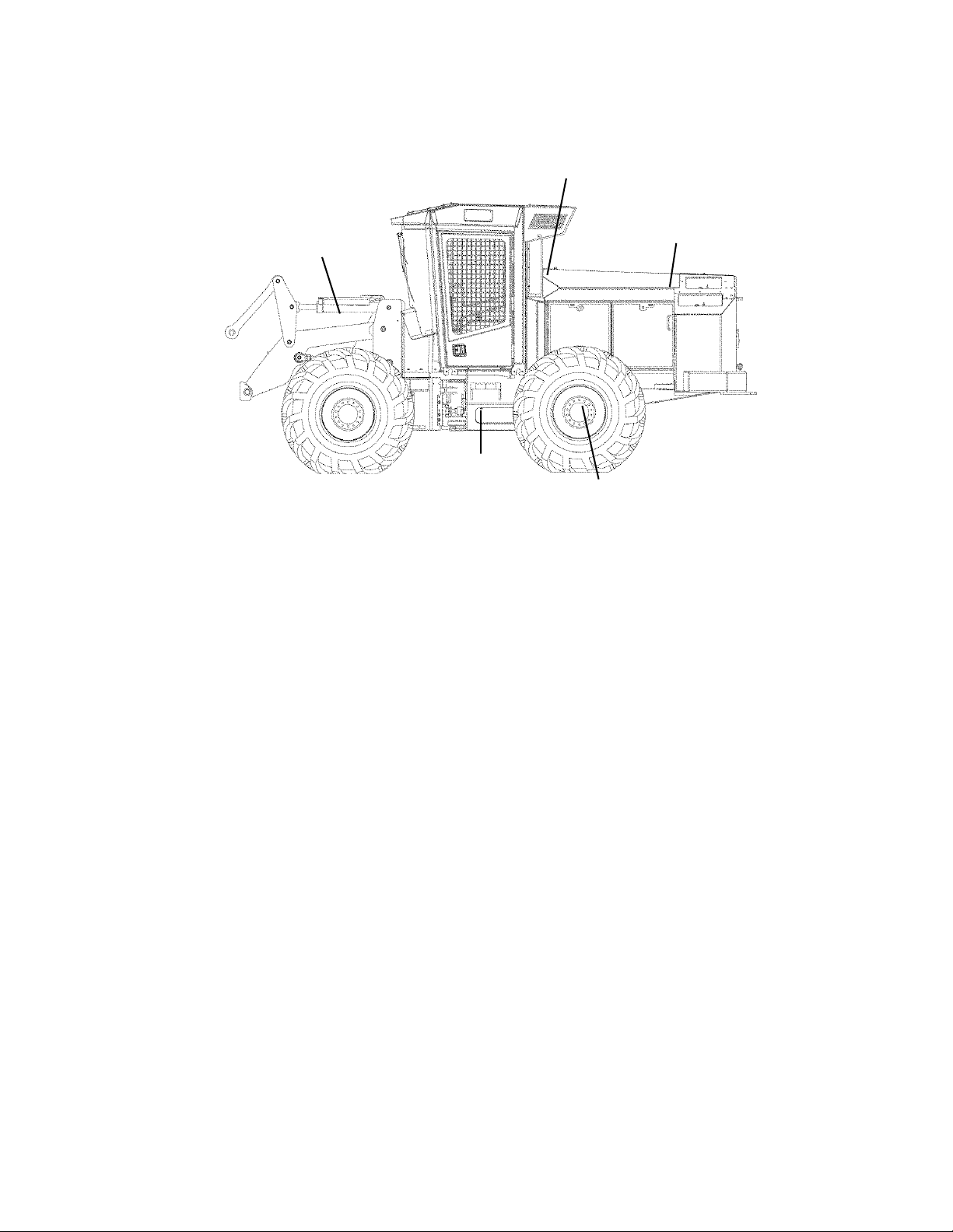
PRE-START INSPECTION
WHERE ARE FIRES MOST LIKELY TO START?
Fires can start almost anywhere on a logging vehicle.
Here are some locations susceptible to fire.
Hydraulic Hoses
and Controls
Parking
Brake
Battery Box
Exhaust Manifold
Engine Block
Turbocharger
G.042.05
Transmission
2570/2670
5-4
0906
Page 85
OPERATION
OPERATION
GENERAL GUIDELINES
Only a trained, qualified, and authorized operator shall be allowed to
operate this machine. Only use this machine after you have carefully read this manual and have
learned how to safely operate and maintain this machine. Unsafe operation can cause severe
personal injury or death.
OPERATOR PREPARATION
Operator must be fully trained, qualified, and
authorized to operate this machine.
Before running this machine, operator must know
the location and purpose of
• controls
• indicator lights
• instruments
100.05
You must be at least eighteen (18) years old to operate this machine (Code of Federal Regulations:
Labor).
Never operate this machine while under the influence of drugs or alcohol. Use of prescription or over-thecounter drugs or medications requires advice from a medical practitioner on whether or not you can safely
operate this machine.
Do not operate this machine if you are subject to dizziness, seizures, or motion disturbance.
No riders are allowed on this machine. Machine riders can fall from machine or be injured by movement
of machinery, causing severe personal injury or death. Do not allow riders on a machine that is operating
or moving.
Follow all safety operating instructions and practices. (See Section 1, General Safety.)
Keep machine away from power lines.
If this manual is lost, contact an authorized dealer for a new manual. Keep manual in the cab.
Report any noticeable machine problems to people who can repair the problems before machine is used.
Be sure cab windows are clean before operating machine. Cab windows must be clear of ice and frost.
Replace windows that are cracked, yellow, and/or hazy.
• local operating safety rules and procedures
• safety and instruction decals (see Section 2,
Safety Decals)
Before using this machine on hills or slopes, see information regarding slope operation in this manual.
Before dismounting from tractor cab, completely stop saw disc rotation by slowly lowering saw disc onto
a tree stump. Saw disc continues to rotate even after attachment on/off switch in cab is turned to ENGINE
OFF position.
Remember, you are key to the safe operation of this machine.
2570/2670 0906
6-1
Page 86
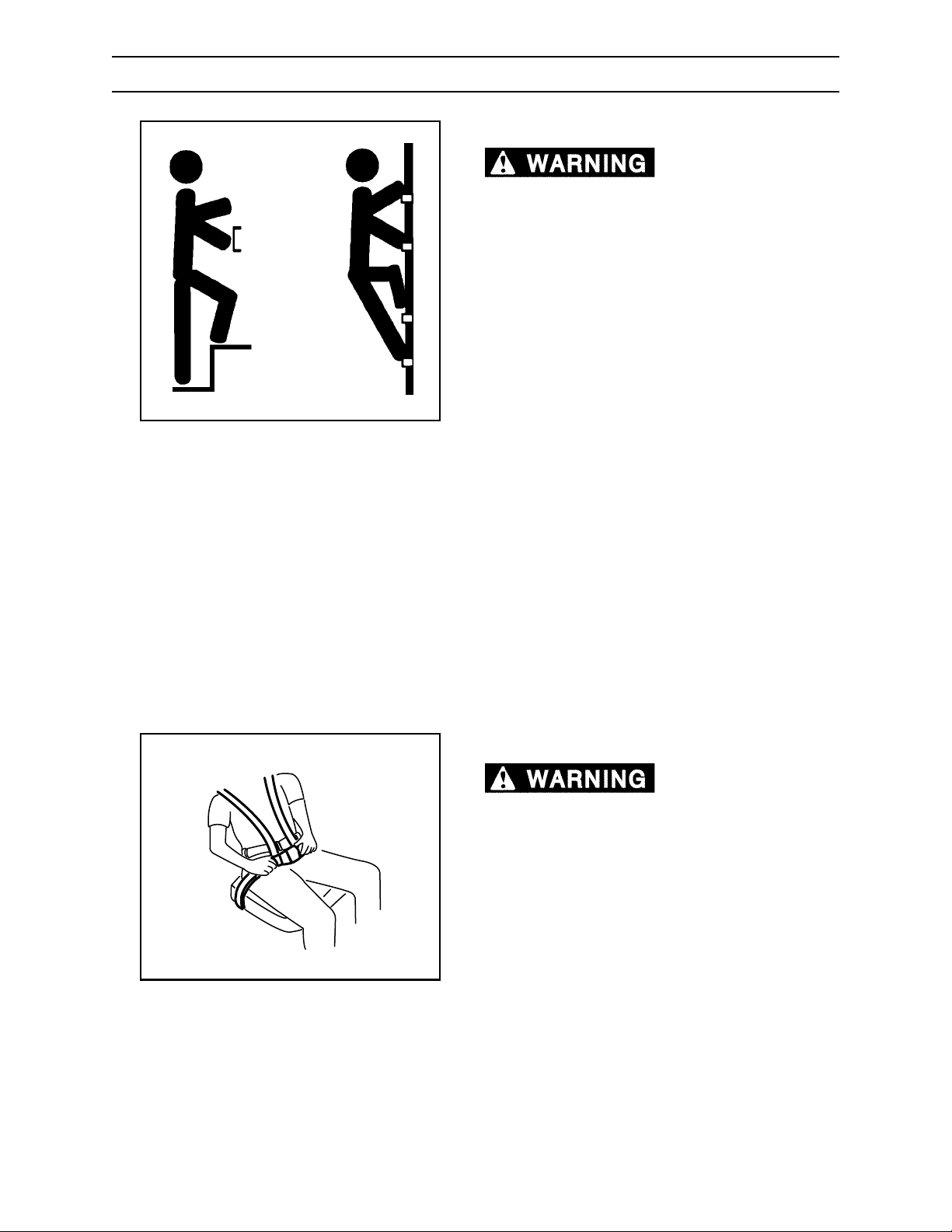
OPERATION
GETTING ON MACHINE
HANDHOLDS AND STEPS
cause serious personal injury.
Use provided handholds and steps while
maintaining at least three (3) points of support (one
foot and two hands or two feet and one hand) when
getting on and off machine. Face machine when
getting on and off it.
Never use controls as handholds. Never use
steering wheel as a handhold. Moving steering
wheel from its center position will COMPLETELY
turn the machine right or left.
DO NOT mount machine if handrails or steps are
G.006.02
broken or missing. Get them repaired first.
DO NOT jump on or off machine unless machine
has touched a live electrical wire and you must
leave it.
Slips and falls can
Ensure firm foot position when getting on and off
machine. Be careful of slippery conditions on
platforms, steps, and handholds when getting on
and off machine.
To prevent slips and falls, replace skid-resistant
material if it is damaged or missing.
Remove all grease, mud, ice, etc., before mounting
or dismounting.
SEAT BELT
A rollover or sudden
stop can cause severe personal injury or death.
Always wear your seat belt, fastened snugly, when
operating machine to reduce the risk of personal
injury resulting from a rollover or sudden stop.
This machine can change direction rapidly. It can
start and stop quickly.
2570/2670
G.017.02
6-2
0906
Page 87
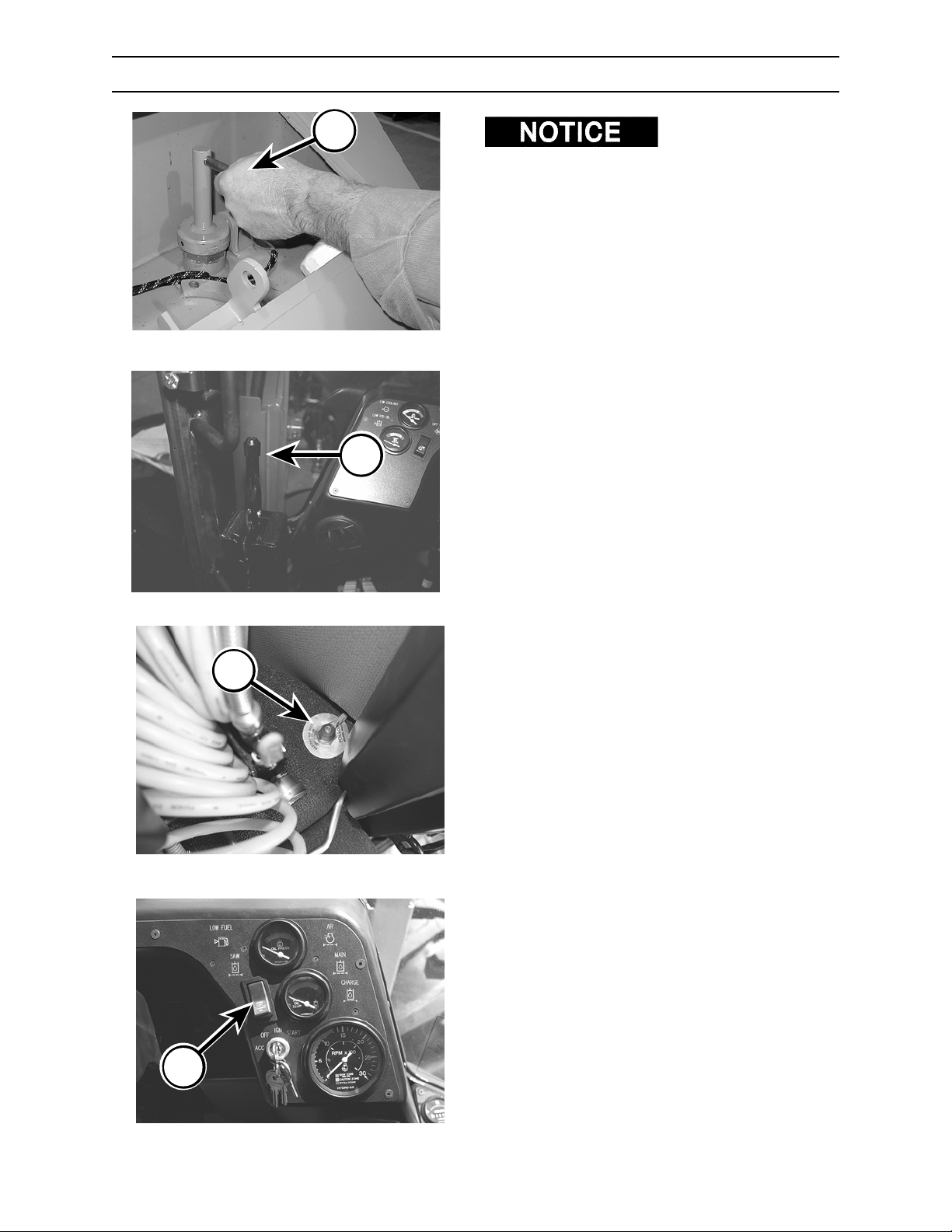
OPERATION
STARTING THE ENGINE
C
A
B
5/670.044.02
5/670.004.02
Before starting engine,
refer to Section 5, Pre-Start Inspection. Be sure
shipping/storage plate is removed from exhaust
outlet before starting engine.
1. Be sure shut-off manifold valve (A) in rear
frame is open (see Section 4, Controls and
Instruments, for proper valve operation).
2. Close cab door and fasten seat belt snugly.
3. Remove foot from propel pedals before
attempting to start engine.
4. Set parking brake (B). Engine will not start if
parking brake is released.
If engine starts when parking brake is released,
the interlock system has failed. Shut engine
down and contact an authorized dealer
immediately for system repair.
5. Turn battery disconnect switch (C) ON. The
battery disconnect switch is located behind
operator’s seat.
6. Move attachment on/off switch (D) to ENGINE
START position. Engine will not start if switch is
in ATTACHMENT RUN position.
If engine starts when the attachment on/off
switch is in ATTACHMENT RUN position, the
interlock system has failed. Shut engine down
and contact an authorized dealer immediately
for system repair.
5/670.036.02
D
5/670.005.02
2570/2670 0906
6-3
Page 88
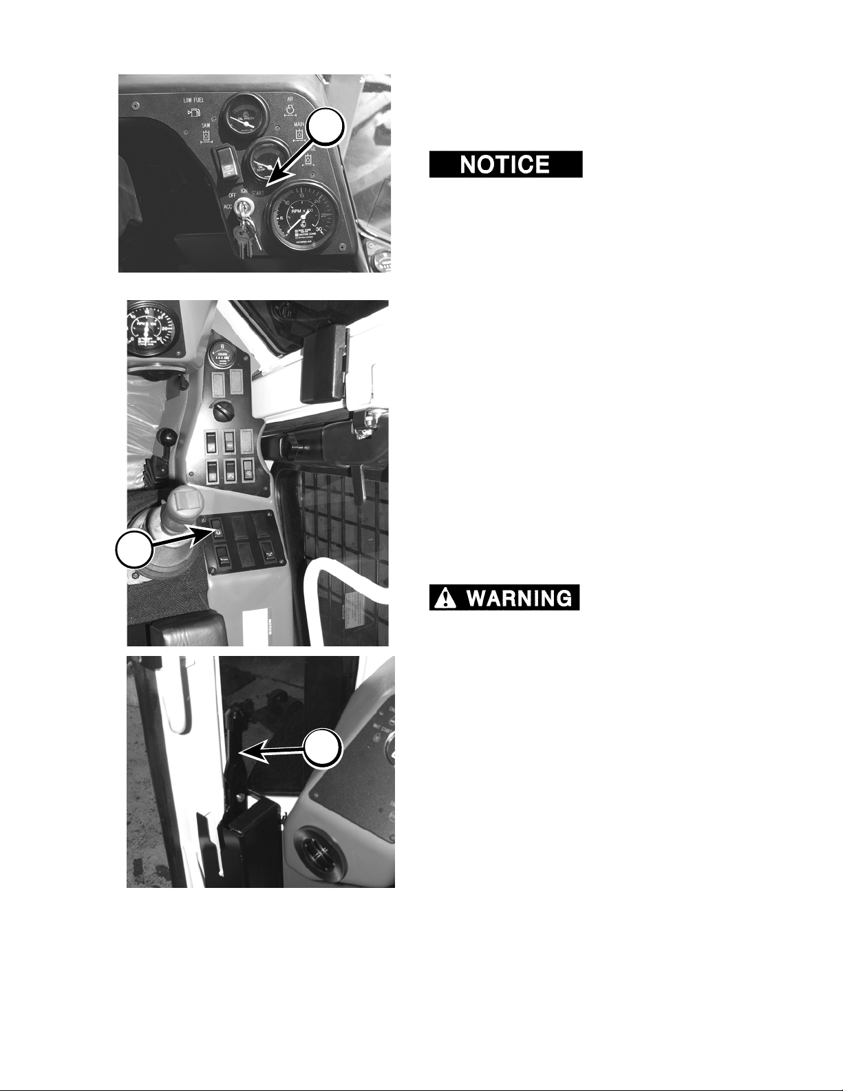
OPERATION
STARTING THE ENGINE
7. Turn key clockwise to ING position. Verify that
A
by pushing or towing machine. Attempting to start
engine by towing or pushing machine will result in
damage to your hydrostatic transmission.
8. Turn key clockwise to START position (A).
5/670.005.02
9. Run engine at half throttle (B) and no load for
the WAIT START indicator is not lighted. If
WAIT START indicator is lit, see COLD
WEATHER START procedure in this section.
Never try to start engine
Release key when engine starts. If engine fails
to start within thirty (30) seconds, turn key to
OFF position and wait at least two (2) minutes
to allow starting motor to cool.
If engine fails to start after four (4) attempts,
troubleshoot and correct the problem.
DO NOT turn key to START while engine is
running. Doing so can cause damage to
starter.
approximately five (5) minutes to allow engine
to warm up.
B
10. After allowing engine and hydraulic
components adequate warm up time, run
engine at full throttle.
11. Before driving machine, release parking brake
(C).
If machine can be
propelled with parking brake engaged, the
interlock system has failed. Shut engine down
and contact an authorized dealer immediately
for system repair.
C
2570/2670
6-4
0906
Page 89
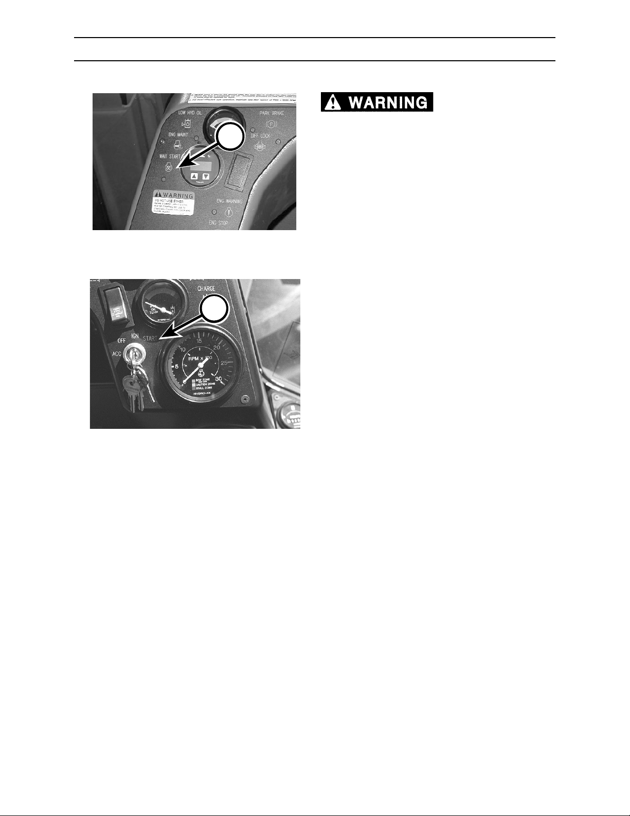
OPERATION
COLD WEATHER STARTING
equipped with a grid air heater. DO NOT use
A
starting fluid under any circumstances. Using
starting fluid on an engine equipped with a grid
air heater may cause a fire and/or explosion
that will result in serious damage to equipment
and may cause serious personal injury or
death.
COLD WEATHER STARTING PROCEDURE
Cummins engine is
B
490.276.02
If the engine temperature is less than 45°F (7°C),
the grid air heater system should be activated as
outlined below.
1. Close cab door and fasten seat belt snugly.
2. Engage parking brake.
3. Turn key clockwise to ING position. The WAIT
START indicator (A) will light. Wait for the
WAIT START indicator to go out.
4. Turn key clockwise to START position (B).
Release key when engine starts. If engine fails
to start within thirty (30) seconds, turn key to
OFF position and wait at least two (2) minutes
to allow starting motor to cool.
If engine fails to start after four (4) attempts,
troubleshoot and correct the problem.
DO NOT turn key to START while engine is
running. Doing so can cause damage to
starter.
2570/2670 0906
6-5
Page 90
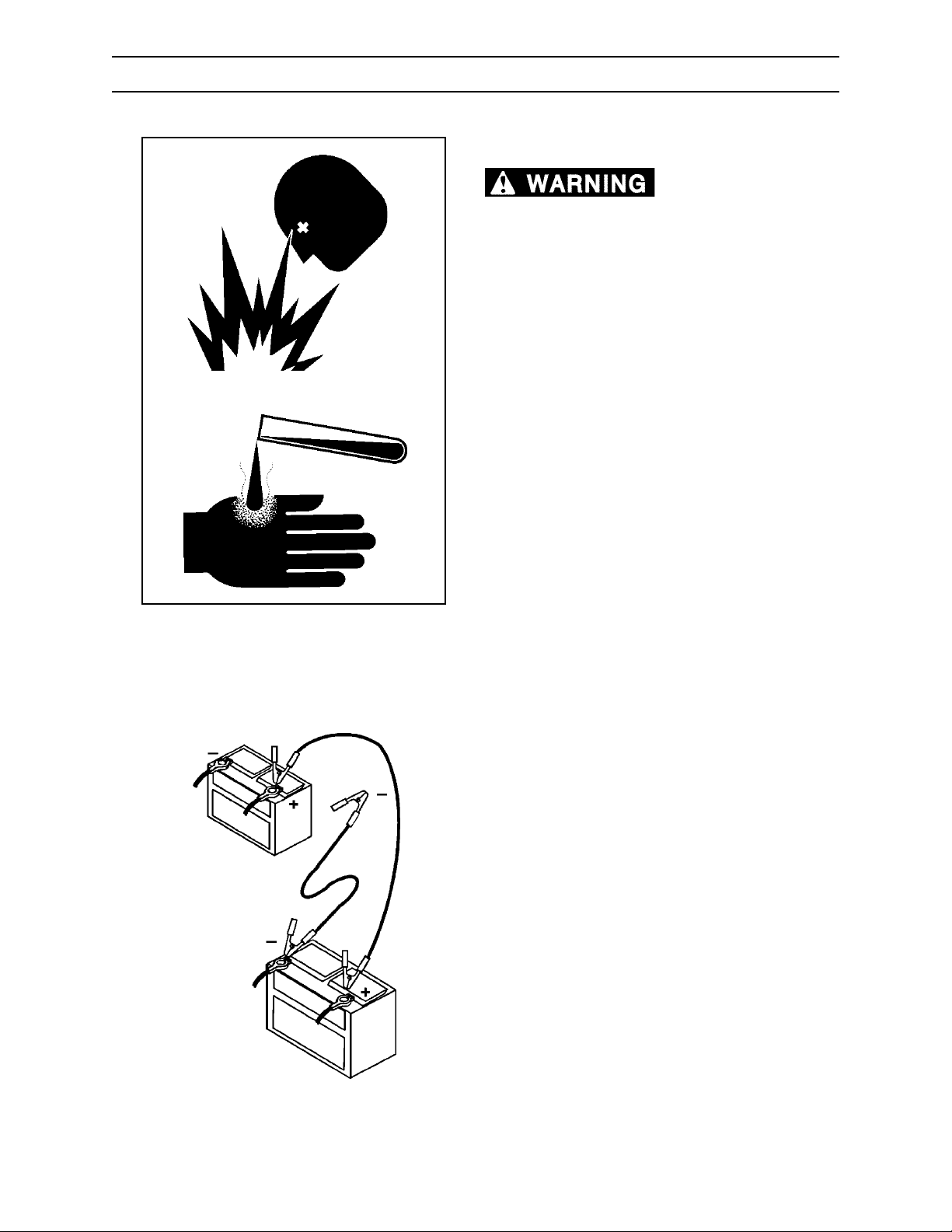
OPERATION
JUMP STARTING BATTERY
If the engine will not crank, batteries may need a
jump start.
explosive gases.
Keep sparks, flames, and cigarettes away from
batteries. Ventilate properly when charging or
using batteries in enclosed space. Always
shield eyes with goggles and wear a face
shield when working near batteries. Do not
lean over batteries during this operation.
Always connect positive (+) to positive (+) and
negative (-) to negative (-). For further
G.019.02
G.013.02
instructions, see Jump Starting Battery in
Section 6, Operation. If battery acid contacts
eyes, flush them with water for 15 minutes and
seek immediate medical attention.
Battery acid is poisonous and can cause
severe burns. If acid is taken internally, call a
physician immediately. If acid contacts skin or
clothing, flush with water immediately. Keep
batteries away from children.
Battery posts, terminals, and related
accessories contain lead and lead
components, chemicals known to the State of
California to cause cancer and reproductive
harm. Wash hands after handling.
Never charge a battery or jump start engine if
battery is frozen. Warm battery to 60
or it may explode. Be sure vent caps are tight.
When jump starting from another machine, be
sure machines do not touch. This machine has
a 12-volt starting system. Use equal voltage
for jump starting.
Batteries produce
°F (16°C)
2570/2670
Machine
Battery
A
C
Booster
Battery
D
B
G.060.02
JUMP STARTING PROCEDURE
1. Turn battery disconnect switch OFF. Remove
key from ignition switch.
2. Clamp one end of first booster cable to positive
terminal of discharged battery (A) (terminal
connected to starter or solenoid).
3. Clamp other end of first booster cable to
positive terminal of booster battery (B).
4. Clamp one end of second booster cable to
negative terminal of booster battery (C).
5. Clamp other end of second booster cable to
engine block or frame of machine (D) (to keep
sparks away from either battery).
6. Insert key in ignition switch. Turn battery
disconnect switch ON.
7. After starting engine, remove booster cables in
reverse order from how you put them on. To
prevent sparks, keep booster cable clamps
from touching.
6-6
0906
Page 91
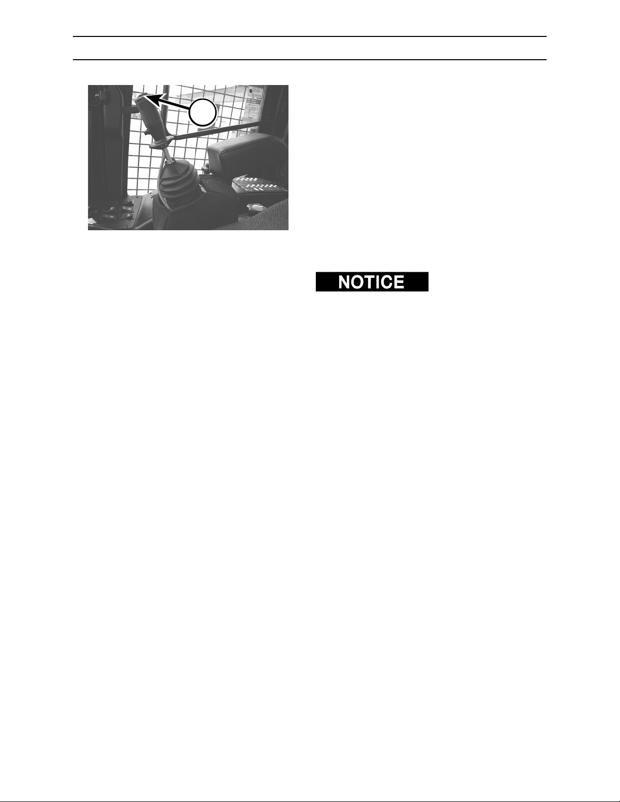
A
OPERATION
WARM UP PERIOD
Before operating, warm up hydraulic system using
the following procedures:
1. Run engine at 1/2 throttle for 3-5 (three to five)
minutes.
2. Hold bunching arm rocker switch (A) either left
or right for ten (10) minutes. Then the opposite
way for ten (10) seconds. Repeat.
3. Hold bunching arm rocker switch (A) then in
the opposite direction for ten (10) minutes.
4. Cycle all hydraulic functions for at least ten
5/670.001.02
(10) minutes. Do not cycle hydraulic cylinders
to the end of their stroke for the first ten (10)
minutes.
temperature falls below 15°F (-9°C) for extended
time periods, an external heat source for engine
and hydraulic system may be required for start up.
When ambient
Below 25°F (-4°C), proper engine warm up is
essential to minimize cavitation. Cold, thick oil
cannot flow fast enough to the pump to meet its
output demand.
2570/2670 0906
6-7
Page 92
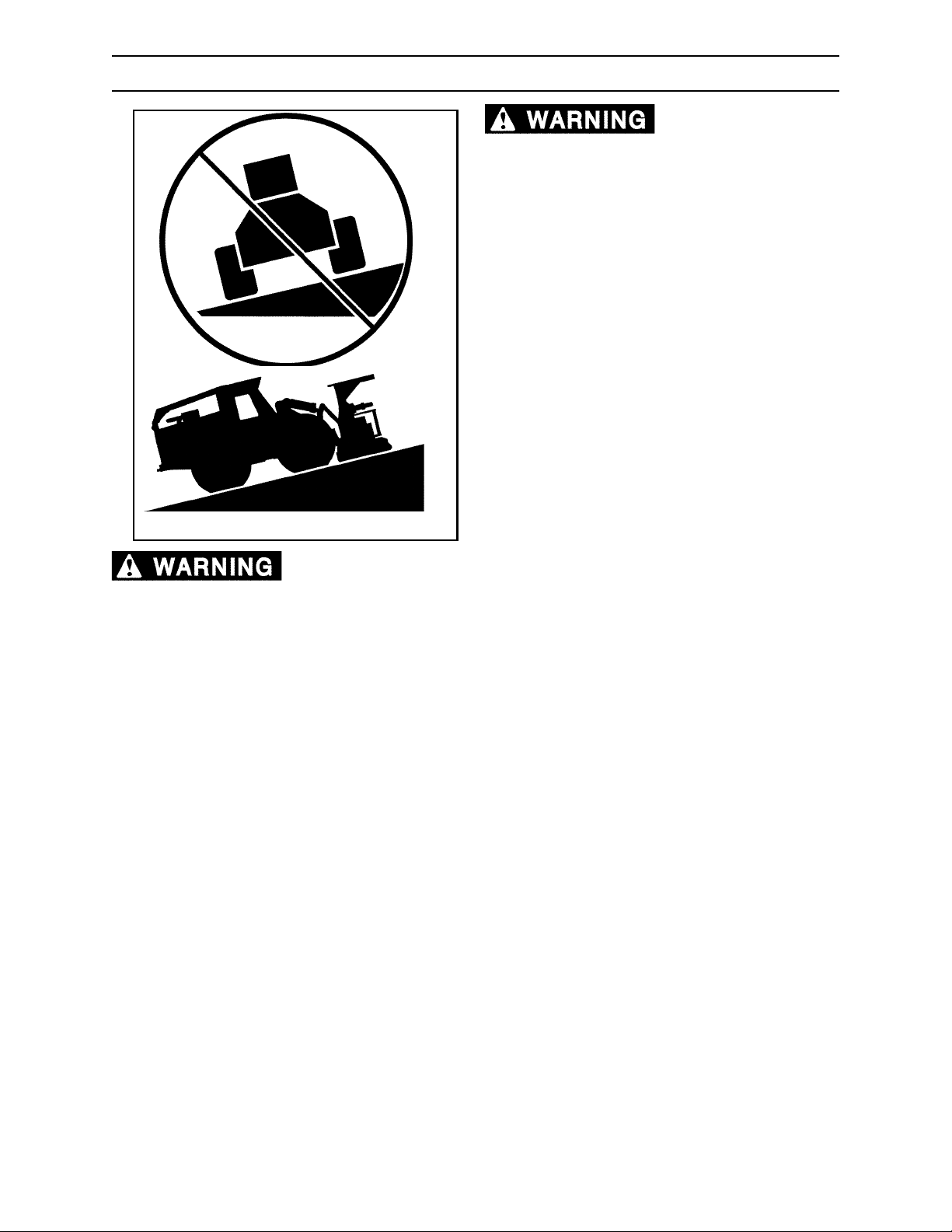
OPERATION
SLOPE OPERATION
slope can cause machine to tip over and may
result in severe injury or death. Loss of traction
on a steep slope can cause operator to lose
control of machine resulting in a roll over,
which may cause severe injury or death.
DO NOT operate with tires sideways to a slope.
Travel straight up and down, that is, with tires
pointed up and down the slope.
ALWAYS wear seat belt snugly fastened.
G.018.02
3’
Operation across a
10’
Failure to observe the following conditions for safe operation can lead to
severe injury or death.
1. Always wear seat belt snugly fastened.
2. Before beginning felling operation, operators must become familiar with a sloped logging site by
walking the site and carefully noting the slope, ground conditions, ditches, drop-offs, and other
hazards.
3. It is impossible to anticipate various conditions an operator may face while harvesting felled trees on
slopes. Therefore, operators should use extreme caution and conservative operating procedures to
avoid risks caused by operating in unstable conditions.
4. Successful and safe slope harvesting operations depend on
G.061.02
• operator skill, judgement, and experience,
• knowing that sudden or jerky machine movement may cause a loss of stability on even
small inclines,
• knowing that smooth, controlled movement is best,
• avoiding soil conditions that could limit traction, such as wet or muddy soil, compacted dirt, or
rocky conditions,
• avoiding terrain conditions that could lead to instability of machine, loss of control, or roll over,
such as slopes, ditches, stumps, and other uneven ground conditions; and,
• using tires with good, unworn tread.
5. On ALL slopes, work only up and down the slope with tires pointed up and down the slope. DO NOT
attempt side slope operations.
6. The machine should not be turned on slopes.
7. Operation of this machine on slopes greater than 30% (16.7°) is not recommended because of the
strong potential for loss of stability resulting in personal injury or death. A 30% slope can be visualized
by a three (3) foot rise in a ten (10) foot distance.
8. Local slope conditions may dictate a lower safe slope limit than 30% (16.7°).
2570/2670
6-8
0906
Page 93
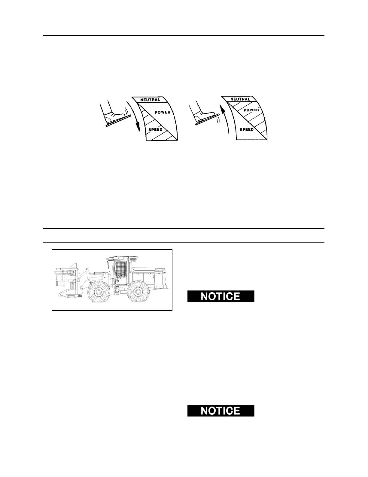
OPERATION
OPERATING THE HYDROSTATIC TRANSMISSION
Variable speed of the hydrostatic transmission is controlled by the forward/reverse propel pedals. The
operator has ability to control the machine for maximum efficiency. Due to its ease of operation, the
hydrostatic transmission is superior to a fixed-speed transmission in adverse operating conditions such as
mud, hills, dense tree stands, and rough terrain.
As propel pedal is
depressed, speed increases
and torque decreases.
PREPARE FOR OPERATION
G.027.02
As propel pedal is
released, speed decreases
and torque increases.
Carry attachment as low as possible without
running into obstacles.
For extended driving (45 minutes or more) on hardsurface roads, follow the procedures below:
DO NOT make
continuous turns with differential locks engaged on
a hard surface. Doing so may damage axles.
1. Inflate tires to 30 psi (200 kPa) ONLY for
extended hard-surface road driving.
2. Check tire temperature every hour of
operation. If tires are too hot to leave your
hand on, stop and wait for tire temperature to
drop.
3. Check hydraulic oil temperature frequently.
Possible pump or hydraulic system damage
can occur if operating for an extended period of
time above 200°F (93°C).
Be sure to decrease tire
pressure when you reach job site. See Section 11,
Scheduled/Periodic Maintenance, for proper
inflation.
2570/2670 0906
6-9
Page 94
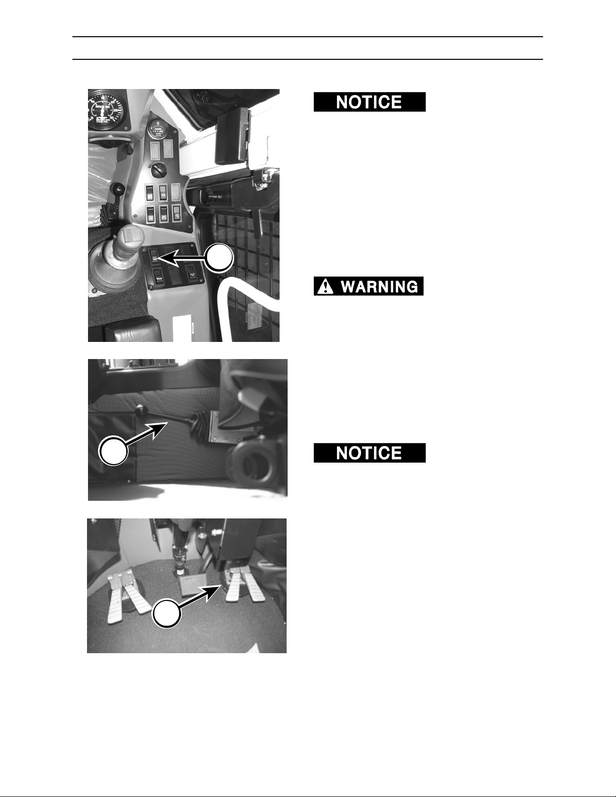
OPERATION
DRIVING THE TRACTOR
sure there are no people near machine or
attachment.
1. Fasten seat belt snugly.
2. With engine and hydraulics warmed up
properly, depress throttle switch (A) to high idle
position.
3. Set transmission shifter (B) to desired (HIGH or
LOW) position.
4. Completely release parking brake. Machine will
A
not move if parking brake is not completely
released.
propelled with parking brake set, interlock
system has failed. Shut engine down and
contact an authorized dealer immediately for
system repair.
Before traveling, make
If machine can be
B
5. Using right joystick control, lift attachment off
the ground. Keep attachment as low as
possible without running into obstructions.
6. Use propel pedals (C) to travel in desired
direction.
To avoid engine damage,
refer to your engine operator’s manual for engine
slope limitations.
5/670.054.02
C
5/670.003.02
2570/2670
6-10
0906
Page 95
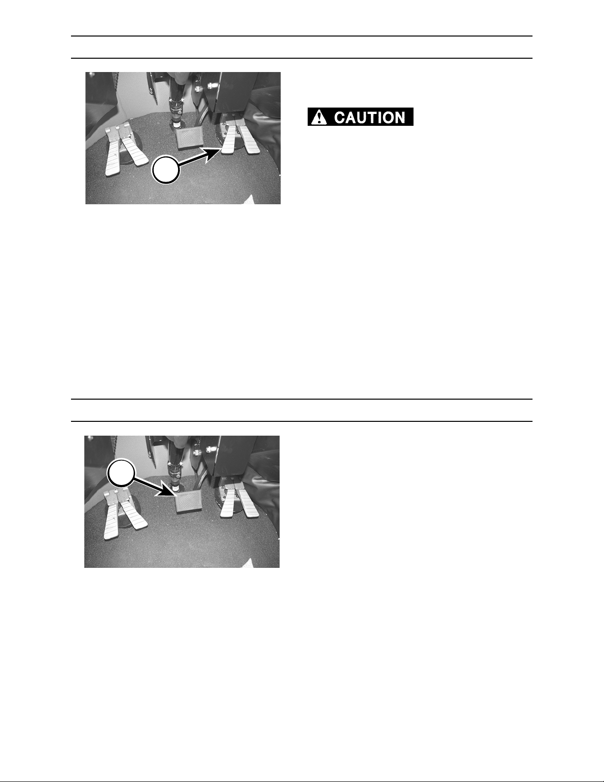
A
OPERATION
STOPPING THE TRACTOR
For dynamic braking, remove foot from propel
pedals (A).
Trying to stop machine
travel in one direction by depressing the pedal
for the opposite direction could cause machine
to come to a stop, and to move abruptly in the
opposite direction. Dynamic braking is best
controlled by simply removing your foot from
the propel pedals.
5/670.003.02
B
SERVICE STOPPING
1. Return propel pedals to neutral.
2. Depress service brake (B).
5/670.003.02
2570/2670 0906
6-11
Page 96
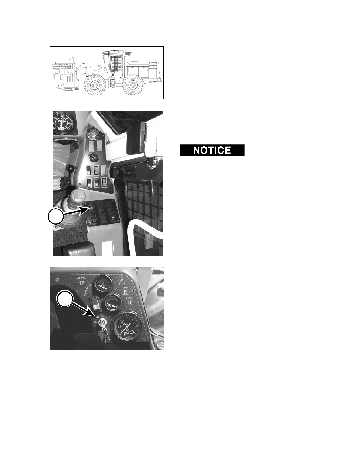
OPERATION
STOPPING THE ENGINE / PARKING THE MACHINE
1. Stop machine on level ground.
G.027.02
2. Depress throttle switch (A) to LOW IDLE
position and run engine for three to five (3-5)
minutes with no load to allow engine to cool
gradually and uniformly.
Before dismounting
machine, completely stop saw disc rotation by
slowly cutting into a stump. Saw disc will continue
to rotate after saw switch is turned OFF.
3. Lower attachment to the ground.
A
B
4. Set parking brake.
5. Shut off engine by turning key to OFF
position (B).
6. Relieve hydraulic pressure by moving control
levers.
7. Remove key from ignition switch.
5/670.005.02
2570/2670
6-12
0906
Page 97
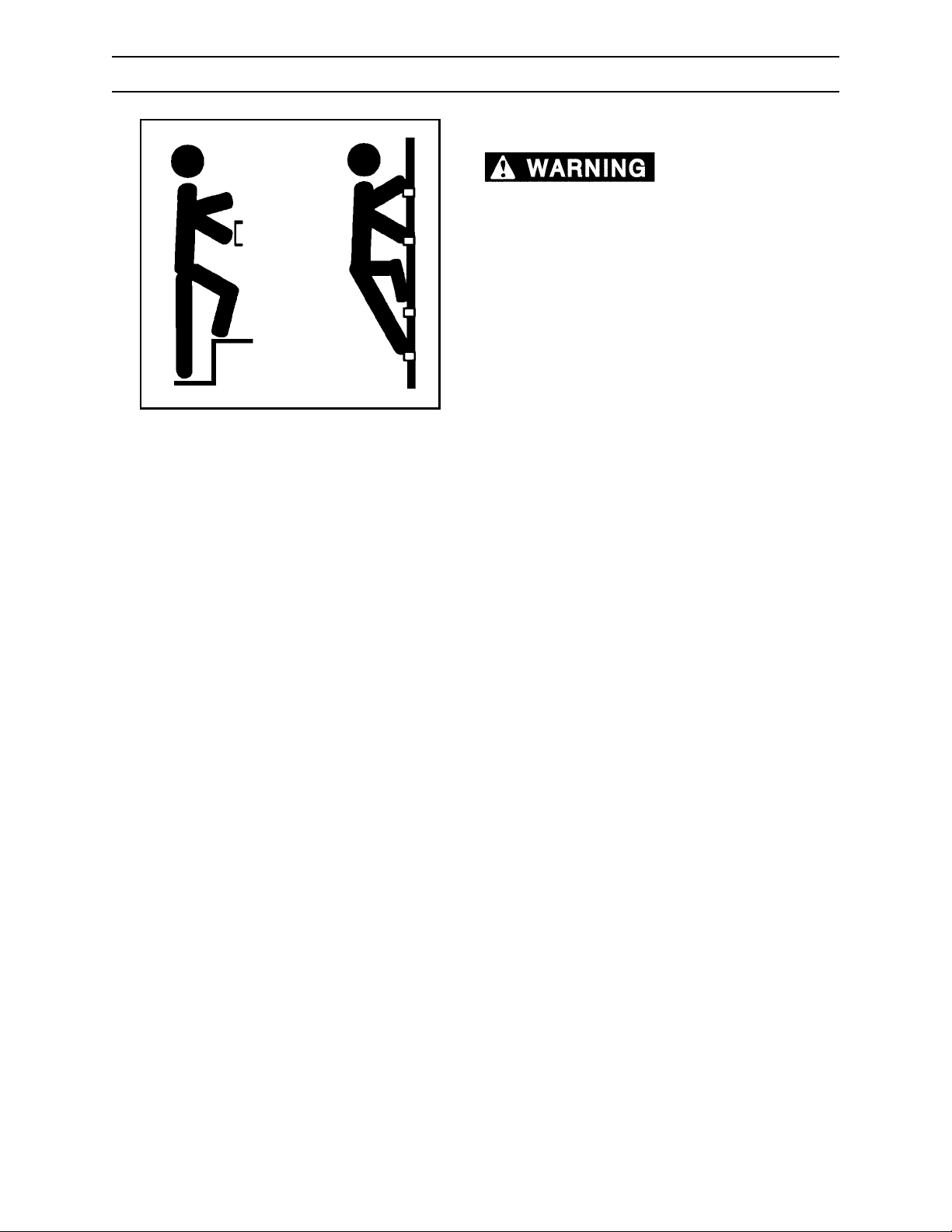
OPERATION
GETTING OFF MACHINE
HANDHOLDS AND STEPS
cause severe personal injury or death.
Use provided hand holds and steps while
maintaining at least 3 points of support (1 foot and
2 hands or 2 feet and 1 hand) when getting on and
off machine. Face machine when getting on and
off of it.
Never use controls as hand holds. Never use
steering wheel as a hand hold. Moving the steering
wheel from its center position will COMPLETELY
turn machine right or left.
Slips and falls can
G.006.02
DO NOT mount machine if hand rails or steps are
broken or missing. Get them repaired first.
DO NOT jump on or off machine unless it has
touched a live electrical wire and it must be exited.
Ensure firm foot position when getting on and off
machine. Be careful of slippery conditions on
platform, steps, and hand holds when getting on
and off machine.
Remove oil, grease, mud, ice, etc. before mounting
or dismounting machine.
To prevent slips and falls, replace skid-resistant
material if it is damaged or missing.
2570/2670 0906
6-13
Page 98
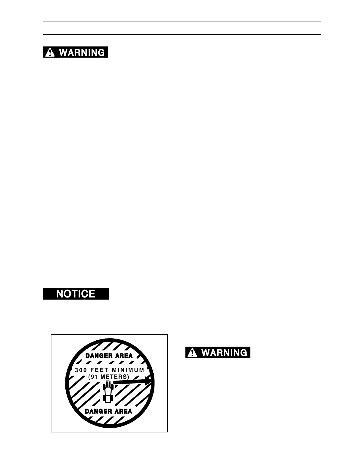
OPERATION
OPERATING THE SS56 & SH56 SAW (SINGLE CUT)
Failure to follow these safety and operation guidelines can lead to severe
injury or death.
SAFETY GUIDELINES
1. Flying debris, falling trees, limbs, and tops from bunching saw can cause severe injury or death. DO
NOT operate BUNCHING SAW within 300 feet (91 m) of personnel or machinery.
2. ALWAYS keep both cab doors closed while operating machine. Flying debris can cause serious
personal injury.
3. BEFORE getting out of machine, be sure the bunching saw disc rotation has completely stopped.
OPERATION GUIDELINES
1. Fell trees in direction of the wind.
2. Fell tree in direction of weighted (heavy) side of tree.
3. NEVER cut trees with saw disc speed in stall zone shown on saw tachometer.
4. Keep saw teeth SHARP!! Dull saw teeth rob horsepower.
5. Fell tree with a maximum of 18 or 22 inches (46-56 cm), depending on saw size, on the butt end of
the tree.
6. Travel with saw as low to the ground as possible without running into obstructions.
7. NEVER make the final cut of tree with the side cut. The weight of a fully cut tree on saw disc will
cause damage to saw disc.
8. (Blount bunching saw disc) NEVER attempt to saw a tree if, at the start of the cut, the saw disc
rpm is less than 1000. DO NOT FORCE A SAW CUT. DAMAGE WILL RESULT.
9. Keep saw speed between 1000 -1300 rpm while making cut. If the saw speed is lower than 700 rpm,
the saw disc could stall. If saw disc stalls, back away from cut (kerf) and let disc rpm speed up to
1000 -1300 rpm. Return to cut (kerf) and continue cutting.
10. Saw disc will continue to rotate after attachment switch is turned to ENGINE START position.
BEFORE leaving machine, completely stop disc rotation by SLOWLY cutting into a stump.
If your saw is equipped with a Quadco saw disc, refer to Quadco’s safety and
operating guide for proper saw disc speeds and maintenance.
SAW OPERATION DANGER AREA
Flying debris, falling
trees, limbs, and tops can cause severe injury
or death. Do not operate saw within 300 feet (91
meters) of personnel or machinery.
2570/2670
G.011.02
6-14
0906
Page 99
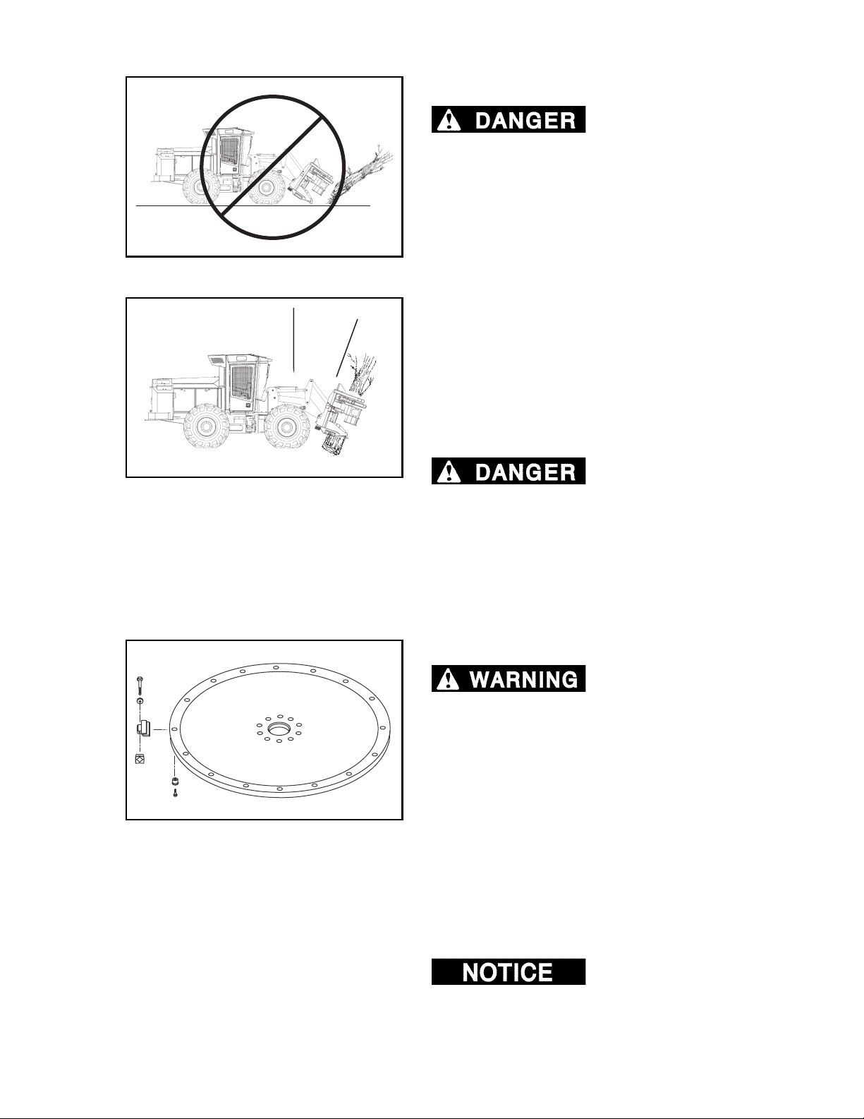
OPERATION
SS56 & SH56 SAW (SINGLE CUT)
DANGEROUS OPERATION PRACTICES
FELLER BUNCHERS TO HARVEST TREES IN A
FALLEN OR BLOWN OVER CONDITION.
SERIOUS PERSONAL INJURY OR DEATH MAY
RESULT FROM HIGH VELOCITY PROJECTILES
BEING THROWN THROUGH THE CAB WINDOW.
Blount feller bunchers are intended to fell standing
102.05
trees, not for harvesting fallen or blown over trees.
Do not use Blount feller buncher to cut when the
head and saw disc are tilted forward from the cab
more than 20°. Such use may result in high velocity
20°
projectiles, like wood pieces, being thrown with
enough force to penetrate cab window. Projectiles
penetrating the cab windows or entering the cab can
cause serious personal injury or death.
The polycarbonate windows are designed to
standard specifications that offer protection under
most conditions of normal operations.
DO NOT USE BLOUNT
103.05
8464
BLOUNT FELLER
BUNCHERS ARE NOT DESIGNED TO HARVEST
FALLEN OR BLOWN OVER TREES, DOING SO
CAN CAUSE SERIOUS PERSONAL INJURY OR
DEATH.
OPERATION IN ROCKY TERRAIN
Flying debris, falling
trees, limbs, and tops can cause severe injury or
death. Do not operate saw within 300 feet (91
meters) of personnel or machinery.
Operating feller buncher in rocky conditions is
hazardous and should be avoided. If felling in rocky
conditions cannot be avoided the following
precautions should be taken:
• Use only solid steel teeth. DO NOT use carbide
tipped teeth.
• Make the cut high enough to clear the rocks.
• Never intentionally let the disc hit a rock
• ONLY fell with the disc horizontal and the
bunching head vertical. DO NOT cut with the
feller buncher head tipped forward.
Teeth breaking when hitting
a rock can damage the tooth seat on the saw disc. It
is more economical to use a segmented disc. When
a broken tooth damages the tooth seat, usually only
the tooth and the segment has to be replaced
instead of a whole disc.
2570/2670 0906
6-15
Page 100

B
OPERATION
SS56 & SH56 SAW (SINGLE CUT)
BUNCHING SAW START UP
1. After starting engine, release parking brake
(A).
A
trees, limbs, and tops from bunching saw can
cause severe injury or death. Do not operate
bunching saw within 300 feet (91 m) of
personnel or machinery.
5/670.004.02
2. With engine at FULL rpm, activate saw by
depressing attachment on/off switch (B) to the
ATTACHMENT RUN position.
Flying debris, falling
5/670.005.02
G.062.02
BUNCHING SAW OPERATION
BEFORE operating saw, determine sequence to
saw trees.
2570/2670
6-16
0906
 Loading...