

Premio Computer Aries Centella User Manual

Aries/Centella
user manual

System Manual

ii Premio System Manual
Copyright
Premio is a registered trademark of Premio Computer, Inc. All other
brands and product names are trademarks or registered trademarks of their
respective companies.
© 1997 by Premio Computer, Inc. All rights reserved.
Printed in Taiwan.
Aries, May 2000.
Disclaimers
Premio makes no representation or warranties, either expressed or
implied, with respect to the contents of this publication and specifically
disclaims the implied warranties of merchantability or fitness for a
particular purpose. Premio shall not be liable for technical or editorial
errors or omissions in this publication, or for incidental or consequential
damages resulting from the furnishing, performance, or use of this
publication. We reserve the right to revise this publication and to make
changes from time to time in its contents without notification.

Getting Started iii
Contents
GETTING STARTED.............................................................. 1
Setting Up ...................................................................................... 2
Switches and Indicators ............................................................... 3
UPGRADING.......................................................................... 5
Opening the System Unit .............................................................6
Installing an Expansion Card....................................................... 7
Installing a Hard Drive ..................................................................8
GETTING HELP ..................................................................... 9
Troubleshooting............................................................................ 9
Monitor Does Not Work...................................................... 9
Keyboard Does Not Work ................................................10
Mouse Does Not Work.....................................................10
System Unit Problems .....................................................11
Hard Drive Problems........................................................ 11
Technical Support.......................................................................12
Premio on the Internet ................................................................ 12

iv Premio System Manual
APPENDIX............................................................................13
Warranty Policy ...........................................................................13
Service Under Warranty...................................................14
Exclusions from Limited Warranty Programs...................14
FCC Standards ............................................................................15
Important Safety Instructions ....................................................16
Getting Started
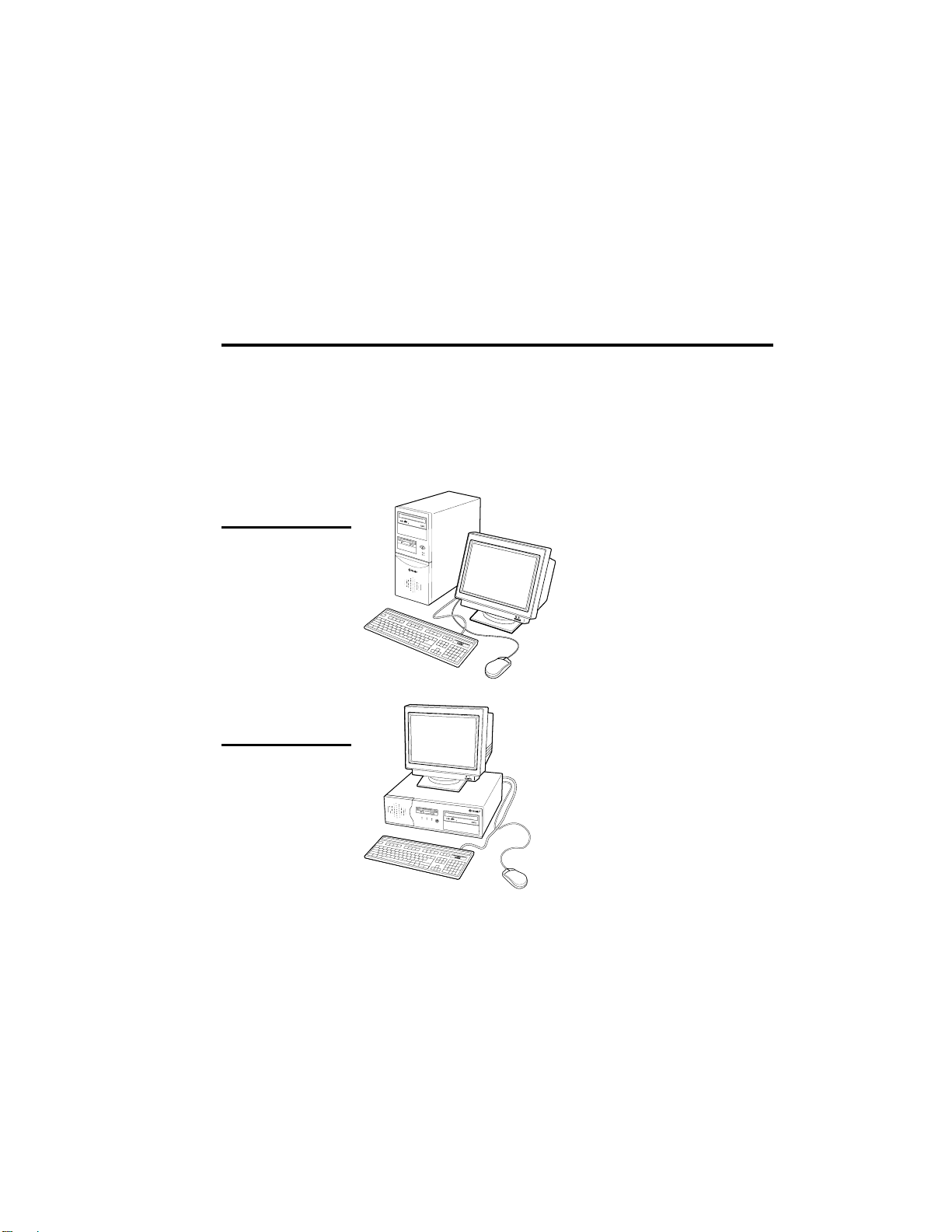
Your Premio® system consists of three components:
a mid-tower or desktop system unit
a keyboard
a mouse
Add your choice of monitor, and your system is ready to use.
System Unit
Mid-tower system
Desktop system
Keyboard
Keyboard
Mouse
System Unit
Mouse
2 Premio System Manual
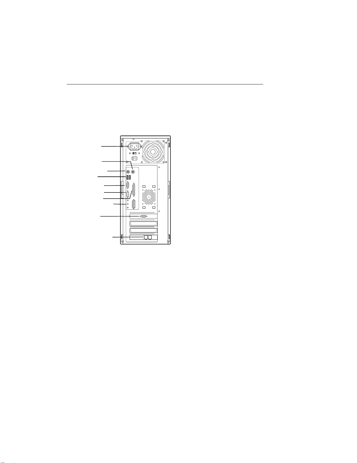
Setting Up
To set up your Premio system, simply connect your monitor, the mouse,
the keyboard, and any additional components you want to use to the
system unit.
Follow these easy steps:
Power Connector
Mouse Connector
Keyboard Connector
USB Connector
Serial-1 Connector
Serial-2 Connector
Parallel Connector
Sound Card Connectors
Video Connector
Modem Connectors
6
Plug your monitor’s power cord into a power outlet.
7
Attach the female end of the system power cord to the
system unit’s power connector, and then plug the other end
of the cord into a power outlet.
Your Premio system is now ready to use. To start the system, turn on your
monitor’s power switch and then press the system power switch as shown
on the next page.
1
Attach your monitor’s video cable to
the video connector.
2
Attach the mouse cable to the mouse
connector.
3
Attach the keyboard cable to the
keyboard connector.
4
Attach the cables for any additional
components, such as a printer,
scanner, or modem, to the respective
parallel, serial, or universal serial bus
(USB) connector, as directed in the
component’s manual.
5
If your system is equipped for
multimedia, attach your speakers and
microphone to the sound card
connectors.
Getting Started 3
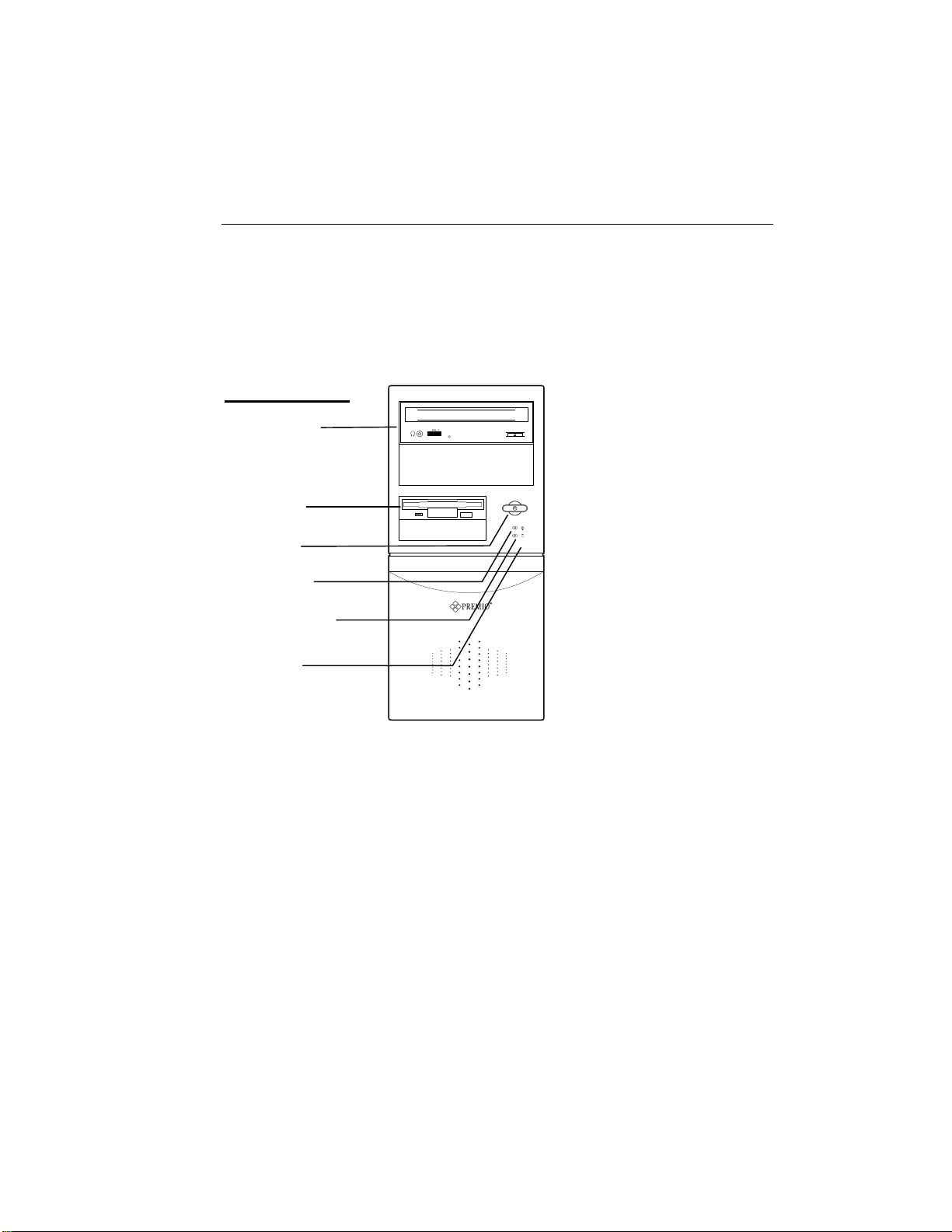
Switches and Indicators
The system unit’s front panel provides access to the CD-ROM and floppy
drives, and to the system’s switches and indicator lights.
The illustration below shows a mid-tower system. If you have a desktop
system, turn to the illustration on the next page.
Mid-tower system
CD ROM Drive
Floppy Drive
Power Switch
Power Indicator
Hard Drive Indicator
Reset Button
The CD-ROM drive reads
information on CDs.
The floppy drive reads and
writes information on
diskettes.
The power switch turns the
system on and off.
The hard drive indicator
lights when the hard drive is
in use.
The power indicator lights
when the system is on.
The reset button restarts the
system.
4 Premio System Manual
h
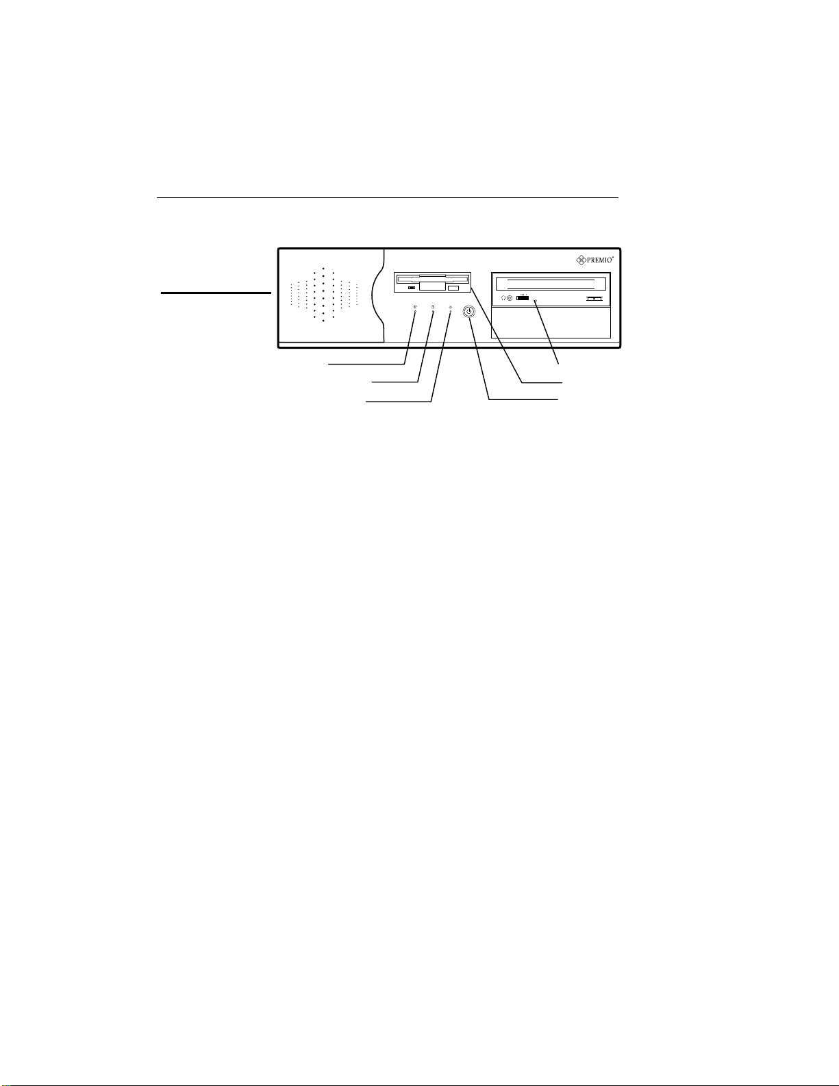
Desktop system
Reset Button
Hard Drive Indicator
Power Indicator
The reset button restarts the system.
The hard drive indicator lights when the hard drive is in use.
The power indicator lights when the system is on.
The power switch turns the system on and off.
The CD-ROM drive reads information on CDs.
The floppy drive reads and writes information on diskettes.
CD ROM Drive
Floppy Drive
Power Switc

Upgrading
You can upgrade your Premio system with:
Expansion cards
More memory
An additional hard drive
To install an upgrade, you must open the system unit. Before
proceeding, read the important cautionary note below. Then follow the
steps on the next page.
Caution! Static discharge can cause permanent damage to internal
electronic components of your computer. Always use the following
precautions when working inside the system unit:
Wear a grounding wrist strap (available at most electronics
stores) when handling electronic components.
Do not remove a component from its antistatic packaging until
you are ready to install it.
Keep one hand in contact with the metal system case.

6 Premio System Manual
Opening the System Unit
Opening the system unit could affect your warranty. Check with
Note:
the dealer where you purchased your system before opening the
system unit.
To open the system unit, follow these steps:
Mid-tower system
Desktop system
1
Turn off the system and
unplug the power cord.
2
Remove the screws
securing the side panel
(mid-tower) or case
(desktop) at the rear of
the system unit.
3
Slide the side panel or
case up and to the rear,
and remove it.
Upgrading 7
Installing an Expansion Card
To install an expansion card, open the system unit as described on the
previous page. Then follow these steps:
1
Remove the screw securing the
slot bracket cover for the
expansion slot you want to use.
Save the screw to secure the
expansion card.
2
Insert the expansion card firmly
into the slot, making sure it is
seated completely.
3
Secure the card with the saved
screw.
8 Premio System Manual
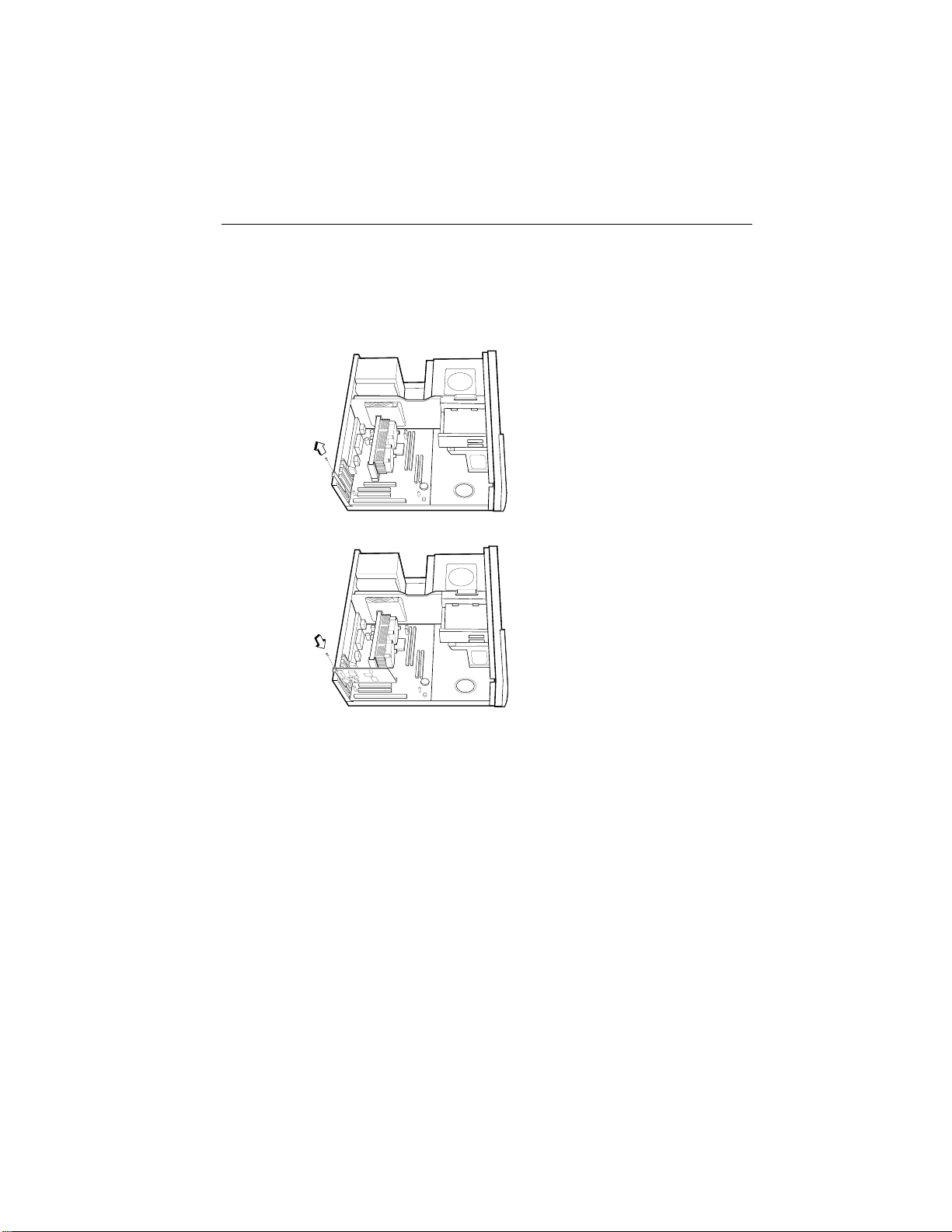
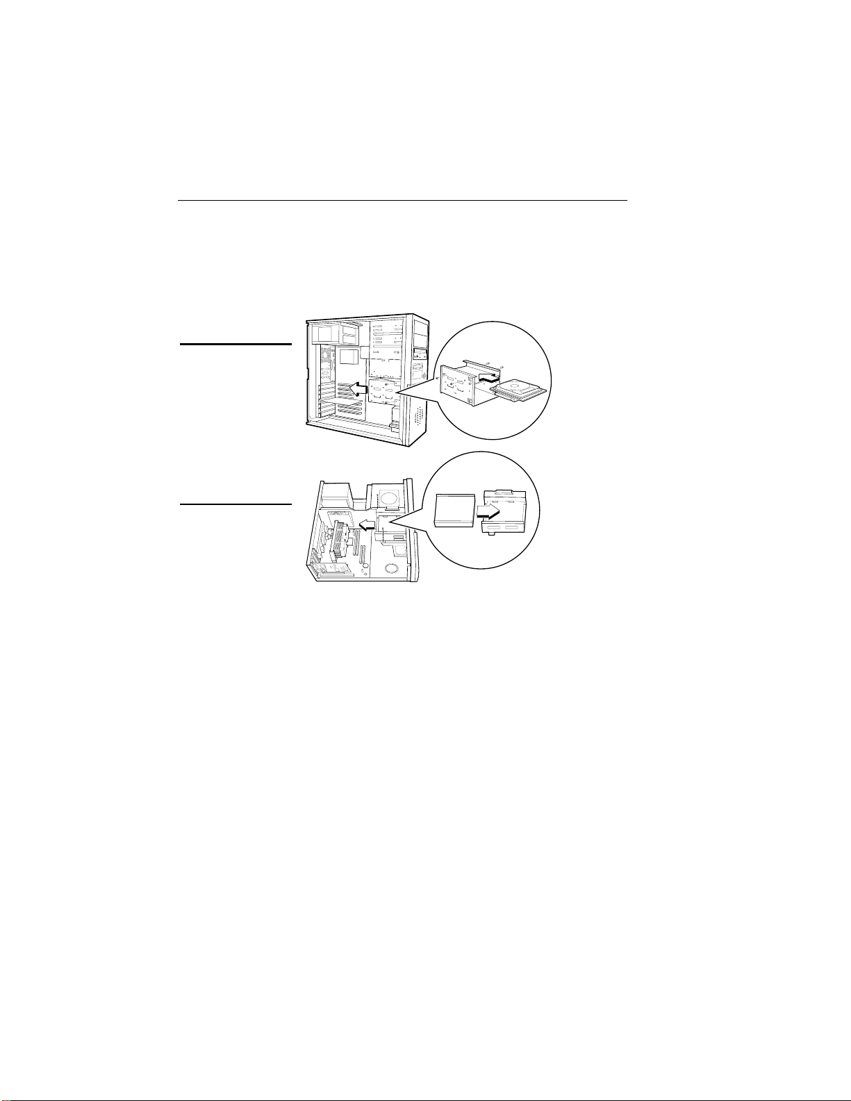
Installing a Hard Drive
To install a hard drive in your system, follow these steps:
1
Disconnect the hard drive cable and power connector.
Mid-tower system
Desktop system
2
Remove the two screws securing the drive bay.
3
Slide the bay toward the rear of the system unit to remove it.
4
Insert the new drive into an open position in the bay and secure
it with four screws.
5
Slide the bay back into the system unit and secure it with two
screws.
6
Connect the cables.

Getting Help
Troubleshooting
Your Premio system is designed to provide years of trouble-free
performance. If you have a problem with your system, first check the
information in this section for a quick solution.
Monitor Does Not Work
If your monitor appears not to be working properly:
Check that the monitor’s power cable is securely attached to
the monitor and to an outlet that is receiving power.
Check that the monitor’s video cable is securely attached to the
monitor and to the system unit’s video card connector.
Check that the monitor’s power switch is on.
Adjust the monitor’s brightness and contrast controls.
If possible, substitute another monitor that is in good working
order. If the substitute works, your monitor may need repair or
replacement.

10 Premio System Manual
Keyboard Does Not Work
If the NumLock indicator in the upper right corner of the keyboard
does not light when the system powers up, or the keyboard does not
work:
Check that the keyboard cable is securely attached to the
system unit’s keyboard connector.
If possible, substitute another keyboard that is in good working
order. If the substitute works, your keyboard may need
replacement.
Mouse Does Not Work
If your mouse pointer does not move or moves erratically when you
move the mouse:
Check that the mouse cable is securely attached to the mouse
connector on the system unit.
Disassemble the mouse and clean the roller ball.

Getting Help 11
System Unit Problems
The fan inside the system unit should make a low, steady sound
when operating properly.
If the fan is totally silent:
Check that the system power cord is securely attached to the
back of the system unit and to a power outlet. Verify that the
outlet has power.
If possible, substitute another power cord that is in good
working order. If the substitute works, replace your power
cord.
If the fan makes excessive noise:
Turn off the system, open the system unit case, and inspect the
fan for any obstructions.
Turn on the system and listen closely to the fan. If the noise
comes from inside the fan housing, your power supply may
need replacement.
Hard Drive Problems
Your hard drive should make a slight whirring sound when operating
properly.
If the drive is totally silent:
Turn off the system, open the system unit case, and check that
the power cable between the power supply and the hard drive
is securely attached at both ends. If it is, your hard drive may
be defective.
If the hard drive makes excessive noise:
Turn off the system, open the system unit case, and remove the
hard drive power cable connector from the hard drive. Then
turn the system back on. If the noise disappears, your hard
drive may be defective.
If you have more than one hard drive, repeat the same
procedure for each drive.

12 Premio System Manual
Technical Support
You can contact Premio technical support at the following address:
Premio Computer, Inc.
918 Radecki Court
City of Industry, CA 91748
Telephone: 626.839.3100
Fax: 626.839.3191
Email: support@premiopc.com
Web page: http://support.premiopc.com
Premio on the Internet
Premio maintains a web page on the Internet with the latest
information on Premio products, updated drivers, answers to
common problems, a troubleshooting guide, and more. Visit our web
page at:
http://www.premiopc.com

Appendix
Warranty Policy
Premio Computer, Inc. warrants its line of Premio® computer systems to
be free from defects in material and workmanship for a specific warranted
period as stated below, from the date of original purchase from Premio
Computer, Inc. or a Premio Computer, Inc. authorized reseller. This
warranty is contingent upon proper use of the product in question and
does not cover products which have been modified or which have been
subjected to unusual physical or electrical stress. Warranty for third party
hardware and software, if any, is subject to the third party's warranty
policy. Please refer to the following for length of warranty for Premio's
product line.
Premio Product Warranty
Complete Premio System with monitor 3 years parts
and labor
Premio Barebone (with or without CPU) 2 years parts
and labor
Premio Monitor 2 year parts and
labor
Premio OEM Component (motherboard, speaker, case,
keyboard, mouse, floppy drive, CD-ROM, etc.)
2 years parts
and labor

14 Premio System Manual
Service Under Warranty
If this product fails to be in good working order during the warranty
period (or specific period of time as noted above), Premio Computer, Inc.
will, at its option, repair or replace the product. Repair parts and/or
replacement products may be either new or reconditioned at Premio
Computer Inc.'s discretion. The limited warranty does not include service
or repair for damage from improper installation, abuse or modifications to
the product not approved in writing by Premio Computer, Inc. Any
service repair outside the scope of this limited warranty will be at Premio
Computer, Inc.'s or its Authorized Service Provider's rates and terms in
effect. This warranty is valid only within the United States, Puerto Rico,
Canada, Mexico and South America.
Exclusions from Limited Warranty Programs
All other expressed and implied warranties for this product are hereby
disclaimed. If this product is not in good working order as warranted
above, Premio Computer's sole and exclusive remedy shall be repair or
replacement as stated above. In no event will Premio Computer, Inc. be
liable to the customer or any third party for any damages in excess of the
purchase price of the product. This limitation applies to damages of any
kind including any direct or indirect damages, lost profits, lost savings or
other special, incidental or consequential damages. This holds true for
situations even if Premio Computer, Inc. or an authorized Premio
representative or dealer has been advised of the possibility of such
damages or of any claim by another party. Some states do not allow the
exclusion or limitation of incidental or consequential damages for some
products, so the above limitation or exclusion may not apply to you.
Premio Computer, Inc. authorized resellers and service providers/partners
may be changed, added or deleted, without notice or liability. Premio
Computer, Inc. disclaims any authorized resellers and service
provider/partner to the program. This warranty gives you specific legal
rights and you may also have other rights, which may vary from state to
state.

Appendix 15
FCC Standards
This equipment has been tested and found to comply with the limits for a
Class B digital device, pursuant to Part 15 of the FCC Rules. These limits
are designed to provide reasonable protection against harmful interference
in a residential installation. This equipment generates, uses and can
radiate radio frequency energy and, if not installed and used in accordance
with the instructions, may cause harmful interference to radio
communications. However, there is no guarantee that interference will not
occur in a particular installation. If this equipment does cause harmful
interference to radio or television reception, which can be determined by
turning the equipment off and on, the user is encouraged to try to correct
the interference by one or more of the following measures:
Reorient or relocate the receiving antenna.
Increase the separation between the equipment and receiver.
Connect the equipment into an outlet on a circuit different from that
to which the receiver is connected.
Consult the dealer or an experienced radio/TV technician for help.

16 Premio System Manual
Important Safety Instructions
These instructions are provided by Underwriters Laboratories, Inc.
1. Read all of these instructions and save them for later reference.
2. Follow all warnings and instructions marked on the product.
3. Unplug this product from the wall outlet before cleaning. Do not
use liquid or aerosol cleaners. Use a damp cloth for cleaning.
4. Do not use this product near water.
5. Do not place this product on an unstable cart, stand or table. The
product may fall, causing serious damage to the product.
6. Slots and openings on the cabinet and the back or bottom are
provided for ventilation. To ensure reliable operation of the product
and to protect it from overheating, do not block or cover these
openings. The openings should never be blocked by placing the
product on a bed, sofa, rug or other similar surface. This product
should never be placed near or over a radiator or heat register. This
product should not be placed in a built-in installation unless proper
ventilation is provided.
7. This product should be operated from the type of power source
indicated on the marking label. If you are not sure of the type of
power available, consult your dealer or local power company.
8. This product is equipped with a 3-wire grounding-type plug, a plug
having a third (grounding) pin. This plug will only fit into a
grounding-type power outlet. This is a safety feature. If you are
unable to insert the plug into the outlet, contact your electrician to
replace your obsolete outlet. Do not defeat the safety purpose of the
grounding-type plug.
9. Do not allow anything to rest on the power cord. Do not locate this
product where the cord will be walked on.
10. If an extension cord is used with this product, make sure that the
total of the ampere ratings on the products plugged into the
extension cord do not exceed the extension cord ampere rating.
Also, make sure that the total of all products plugged into the wall
outlet does not exceed 15 amperes.
11. Never push objects of any kind into this product through cabinet
slots as they may touch dangerous voltage points or short out parts

Appendix 17
that could result in a risk of fire or electric shock. Never spill liquid
of any kind on the product.
12. Except as explained elsewhere in this manual, don't attempt to
service this product yourself. Opening and removing those covers
that are marked “Do Not Remove” may expose you to dangerous
voltage points or other risks. Refer all servicing on those
compartments to service personnel.
13. Unplug this product from the wall outlet and refer servicing to
qualified service personnel under the following conditions:
A. When the power cord or plug is damaged or frayed.
B. If liquid has been spilled into the product.
C. If the product has been exposed to rain or water.
D. If the product does not operate normally when the operating
instructions are followed. Adjust only those controls that are
covered by the operating instructions since improper
adjustment of other controls may result in damage and will
often require extensive work by a qualified technician to
restore the product to normal operation.
E. If the product has been dropped or the cabinet has been
damaged.
F. If the product exhibits a distinct change in performance,
indicating a need for service.
MSI
MICRO-STAR INTERNATIONAL
MS-6534 Micro ATX Mainboard
Version 1.0
G52-MA00417
i
Manual Rev: 1.0
Release Date: August 2001
FCC-B Radio Frequency Interference Statement
This equipment has been tested and found to comply with the limits for a
class B digital device, pursuant to part 15 of the FCC rules. These limits are
designed to provide reasonable protection against harmful interference
when the equipment is operated in a commercial environment. This
equipment generates, uses and can radiate radio frequency energy and, if
not installed and used in accordance with the instruction manual, may cause
harmful interference to radio communications. Operation of this equipment
in a residential area is likely to cause harmful interference, in which case
the user will be required to correct the interference at his own expense.
Notice 1
The changes or modifications not expressly approved by the party
responsible for compliance could void the user's authority to operate the
equipment.
Notice 2
Shielded interface cables and A.C. power cord, if any, must be used in
order to comply with the emission limits.
VOIR LA NOTICE D'INSTALLATION AVANT DE RACCORDER
AU RESEAU.
Micro-Star International MS-6534
Tested to comply
with FCC Standard
For Home or Office Use
ii

Edition
August 2001
Copyright Notice
The material in this document is the intellectual property of MICRO-
STAR INTERNATIONAL. We take every care in the preparation of
this document, but no guarantee is given as to the correctness of its
contents. Our products are under continual improvement and we reserve
the right to make changes without notice.
Trademarks
All trademarks used in this manual are the property of their respective
owners.
Intel and Pentium are registered trademarks of Intel Corporation.
PS/2 and OS/2 are registered trademarks of IBM Corporation.
Windows 98/2000/ME and Windows NT are registered trademarks of Microsoft.
Netware is a registered trademark of Novell.
Award is a registered trademark of Award Software Inc.
AMI is a registered trademark of American Megatrends. Inc.
Revision History
Revision Revision History Date
1.0 First Release August 2001
iii

Safety Instructions
1. Always read the safety instructions carefully.
2. Keep this User’s Manual for future reference.
3. Keep this equ ip ment away from humidity.
4. Lay this equipment on a reliable flat surface before setting it up.
5. The openings on the enclosure are for air convection hence protects the
equipment from overheating. DO NOT COVER THE OPENINGS.
6. Make sure the voltage of the power source and adjust properly
110/220V before connecting the equipment to the power inlet.
7. Place the power cord such a way that people can not step on it. Do not
place anything over the power cord.
8. Always Unplug the Power Cord before inserting any add-on card or
module.
9. All cautions and warnings on the equipment should be noted.
10. Never pour any liquid into the opening that could damage or cause
electrical shock.
11. If any of the following situations arises, get the equipment checked by
a service personnel:
• The power cord or plug is damaged
• Liquid has penetrated into the equipment
• The equipment has been exposed to moisture
• The equipment has not work well or you can not get it work
according to User’s Manual.
• The equipment has dropped and damaged
• If the equipment has obvious sign of breakage
12. DO NOT LEAVE THIS EQUIPMENT IN AN ENVIRONMENT
UNCONDITIONED, STORAGE TEMPERATURE ABOVE 60
0
F), IT MAY DAMAGE THE EQUIPMENT.
(140
0
C
CAUTION: Danger of explosion if battery is incorrectly replaced.
Replace only with the same or equivalent type recommended by the
manufacturer.
iv

Contents
Chapter 1. Introduction ...............................................................1-1
Mainboard Specification ............................................................1-2
Mainboard Layout .....................................................................1-4
Quick Components Guide .........................................................1-5
Key Features ............................................................................1-6
Chapter 2. Hardware Setup ........................................................2-1
Central Processing Unit: CPU ...................................................2-2
Installing the CPU ...............................................................2-2
Installing the CPU Fan ........................................................2-3
CPU Core Speed Derivation Procedure................................2-4
Memory ....................................................................................2-5
Introduction to SDRAM .......................................................2-5
DIMM Modules Combination ...............................................2-6
Installing DIMM Modules .....................................................2-6
Power Supply............................................................................2-7
A TX 20-Pin Power Connector...............................................2-7
A TX 12V Power Connector: JPW1.......................................2-8
Back Panel ...............................................................................2-9
Mouse Connector................................................................2-9
Keyboard Connector .........................................................2-10
USB Connectors ............................................................... 2-10
Parallel Port Connector ..................................................... 2-11
Serial Port Connectors: COM A & COM B ........................2-12
Joystick/Midi Connector....................................................2-12
Audio Port Connectors ......................................................2-12
Connectors .............................................................................2-13
Floppy Disk Drive Connector: FDD1 ..................................2-13
Hard Disk Connectors: IDE1 & IDE2 .................................2-14
Case Connectors: F_P1 & F_P2 .......................................2-15
v

Power Saving Switch Connector: JGS1 ............................. 2-19
Wake On LAN Connector: JWOL1 .................................... 2-19
Wake On Ring Connector: JMDM1 (Optional) ................... 2-20
IrDA Infrared Module Connectors: IR1 & IR2 ......................2-21
Fan Power Connectors: C_FAN1/S_F AN1.........................2-22
CD-In/Aux Line-In/Modem-In Connector: CD_IN1/AUX_IN1/
MDM_IN1..........................................................................2-23
USB Front Panel Connectors: USB1 & USB2 ...................2-24
Front Panel Audio Connector: JAUDIO1 ............................2-25
Jumpers .................................................................................. 2-26
Clear CMOS Jumper: JBA T1 ............................................. 2-26
Slots .......................................................................................2-27
AGP (Accelerated Graphics Port) Slot .............................. 2-27
PCI Slots ..........................................................................2-27
CNR (Communication Network Riser) Slot ........................2-27
PCI Interrupt Request Routing ...........................................2-28
Chapter 3. AWARD® BIOS Setup................................................ 3-1
Entering Setup ..........................................................................3-2
Control Keys .............................................................................3-2
Getting Help..............................................................................3-3
The Main Menu .........................................................................3-4
Standard CMOS Features .........................................................3-6
Advanced BIOS Features ..........................................................3-9
Advanced Chipset Features ....................................................3-13
Integrated Peripherals ............................................................. 3-15
Power Management Setup ......................................................3-19
PnP/PCI Configurations...........................................................3-23
PC Health Status .................................................................... 3-25
Frequency/Voltage Control ......................................................3-26
Load Fail-Safe/Optimized Defaults .......................................... 3-28
vi

Set Supervisor/User Password ................................................3-30
Save & Exit Setup...................................................................3-32
Exit Without Saving.................................................................3-33
Chapter 4. AMI® BIOS Setup......................................................4-1
Entering Setup ..........................................................................4-2
Selecting the First Boot Device .................................................4-2
Control Keys .............................................................................4-3
Getting Help..............................................................................4-4
The Main Menu .........................................................................4-5
Standard CMOS Setup .............................................................4-7
BIOS Features Setup................................................................4-9
Chipset Features Setup ..........................................................4-12
Power Management Setup ......................................................4-14
PNP/PCI Configuration ............................................................ 4-18
Integrated Peripherals ............................................................. 4-20
Hardware Monitor Setup..........................................................4-24
Load Optimal/Fail Safe Defaults .............................................. 4-26
Supervisor/User Password ...................................................... 4-28
IDE HDD AUTO Detection .......................................................4-30
Save & Exit Setup...................................................................4-31
Exit Without Saving.................................................................4-32
Appendix A. Using 4-/6-channel Audio Function ..................... A-1
Installing C-Media Drivers ......................................................... A-2
Hardware Configuration ............................................................ A-2
Software Configuration.............................................................. A-3
Glossary............................................................................................ I
vii

Chapter 1.
Introduction
Introduction
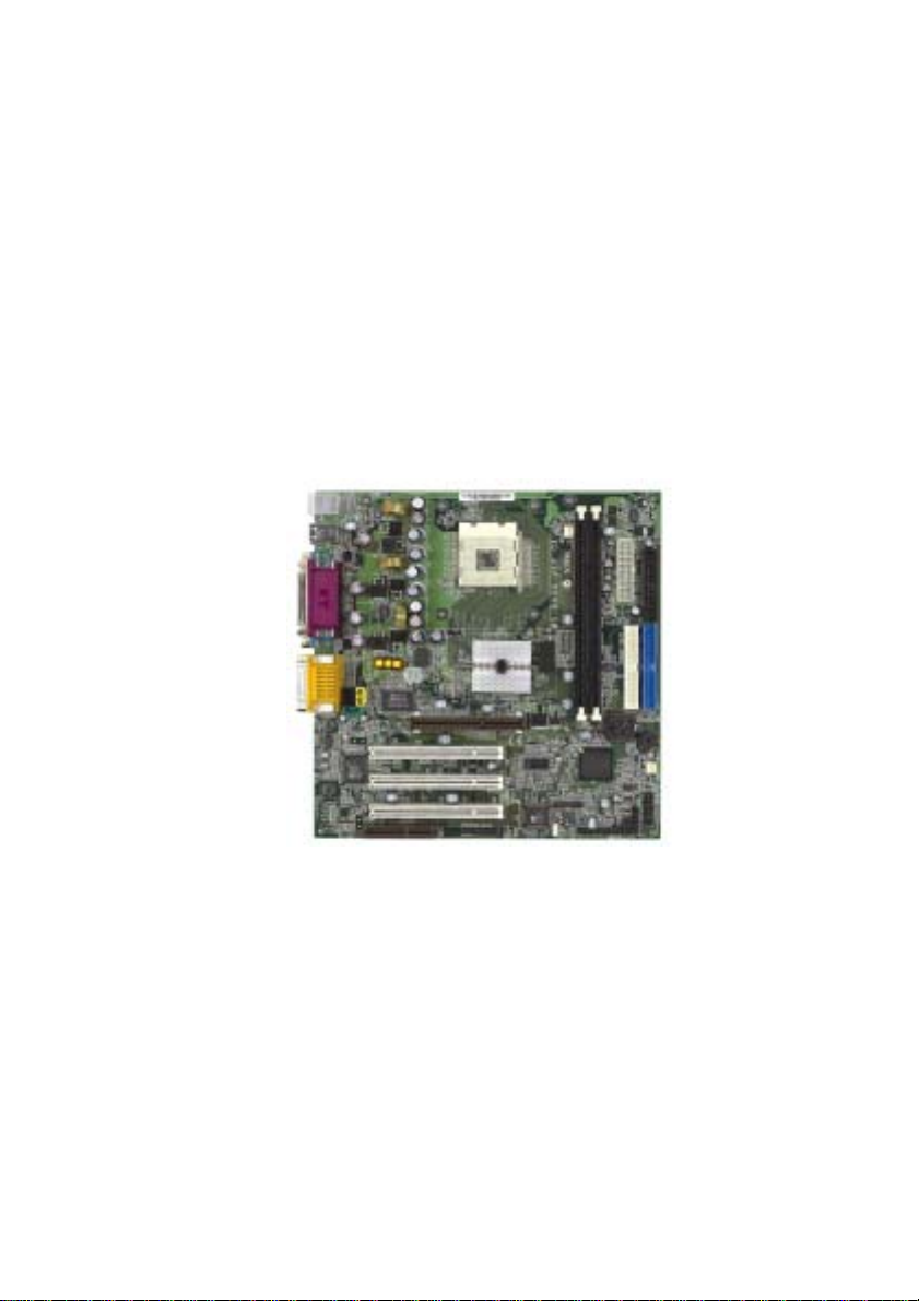
Thank you for purchasing the MS-6534 Micro-ATX motherboard.
The mainboard, based on Intel® Brookdale (82845) & 82801BA chipsets, is
a high-performance computer mainboard designed for Intel® Pentium® 4
processor in the 478 pin package that provides a high-end and professional
desktop platform solution.
This chapter includes the following topics:
Mainboard Specification 1-2
Mainboard Layout 1-4
Quick Components Guide 1-5
Key Features 1-6
1
1-1
 Loading...