

Page 1

Athena System Manual
Page 2

ii PREMIO System Manual
Copyright
PREMIO is a registered trademark of Premio Computer, Inc. All
other brands and product names are trademarks or registered
trademarks of their respective companies.
© 2002 by Premio Computer, Inc. All rights reserved.
Version 1.0, March 2002
Disclaimers
PREMIO makes no representation or warranties, either expressed
or implied, with respect to the contents of this publication and
specifically disclaims the implied warranties of merchantability
or fitness for a particular purpose. PREMIO shall not be liable for
technical or editorial errors or omissions in this publication, or
for incidental or consequential damages resulting from the
furnishing, performance, or use of this publication. We reserve
the right to revise this publication and to make changes from
time to time in its contents without notification.
Page 3

iii PREMIO System Manual
Contents
GETTING STARTED...................................................................5
Setting Up........................................................................6
Connecting Your Keyboard, Mouse, and Speakers ...x
Connecting Your Monitor ..............................................x
Switches and Indicators.................................................8
UPGRADING ............................................................................10
Opening the System Unit.............................................11
Closing the System Unit ................................................x
Installing an Expansion Card ......................................11
Installing Additional Memory.........................................x
Installing an Additional Hard Disk Drive ....................16
GETTING HELP......................................................................... X
Troubleshooting............................................................18
Monitor Does Not Work....................................................... x
Keyboard Does Not Work ....................................................x
Mouse Does Not Work .......................................................19
Page 4

iv PREMIO System Manual
System Unit Problems.........................................................19
Hard Disk Problems ............................................................20
Warranty Service.......................................................... 20
Technical Support........................................................ 21
PREMIO on the Internet............................................... 21
APPENDIX................................................................................22
Limited 3-Year Warranty.............................................. 22
FCC Standards .............................................................24
Important Safety Instructions..................................... 25
Page 5
Getting Started
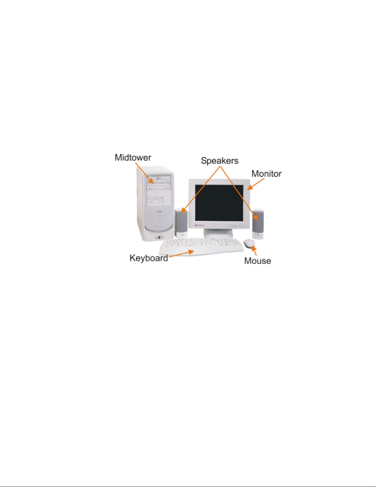
Your PREMIO® Athena system typically consists of five main components:
§ Midtower
§ Monitor
§ Speakers
§ Keyboard
§ Mouse
Depending on which components you’ve ordered with your Athena system, the
components shown in the picture above may vary.
Page 6
6 PREMIO System Manual
Setting Up
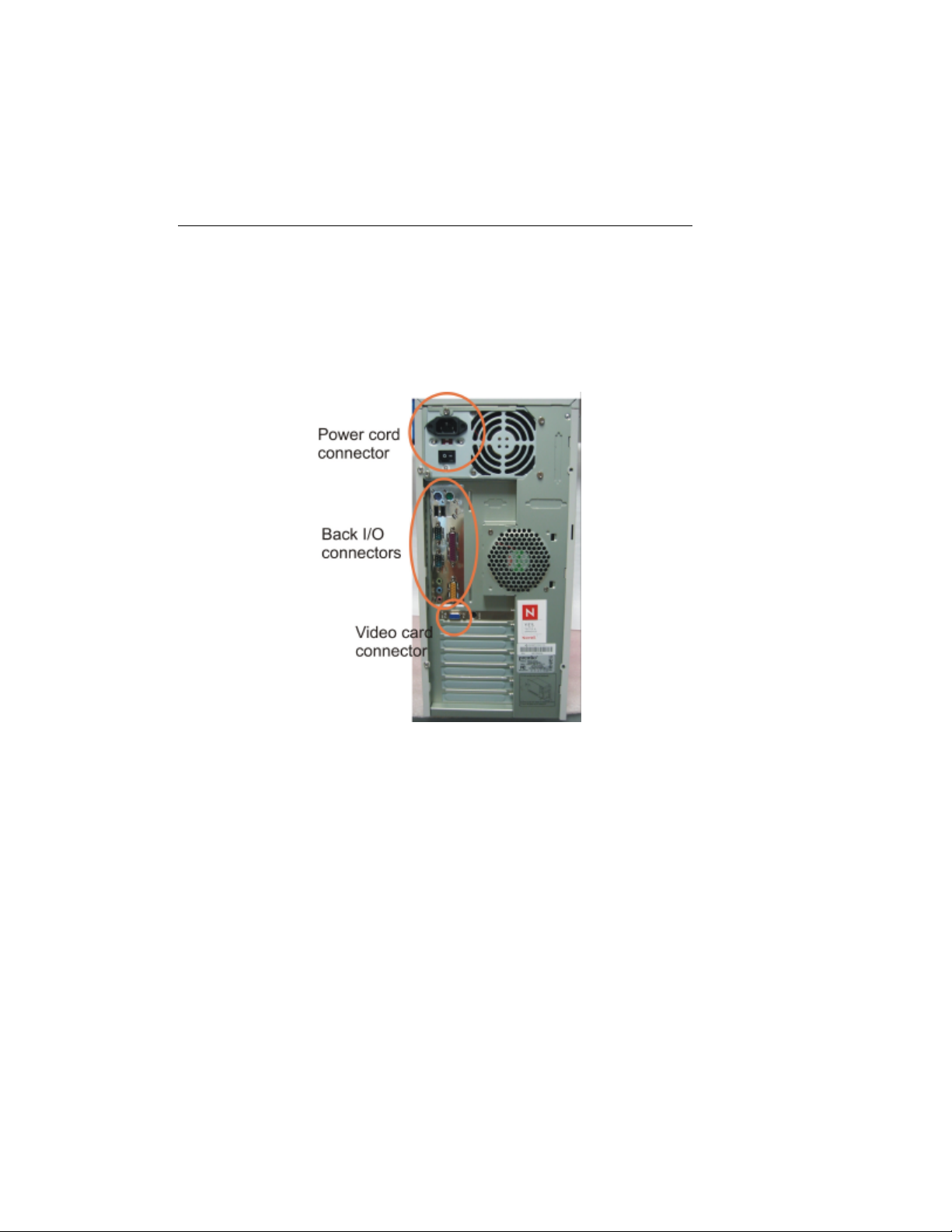
To set up your Athena system, simply connect your monitor, mouse, keyboard, and
speakers to the rear of the midtower.
1. Connect the female end of the power cord to the chassis power cord
connector, and then connect the male end of the power cord to your wall
outlet or power strip
2. Connect the keyboard, mouse, speakers (if any) to the back I/O connectors
(see next page for details)
3. Connect your monitor to the video card connector
Page 7
7 PREMIO System Manual
Connecting Your Keyboard, Mouse, and
Speakers
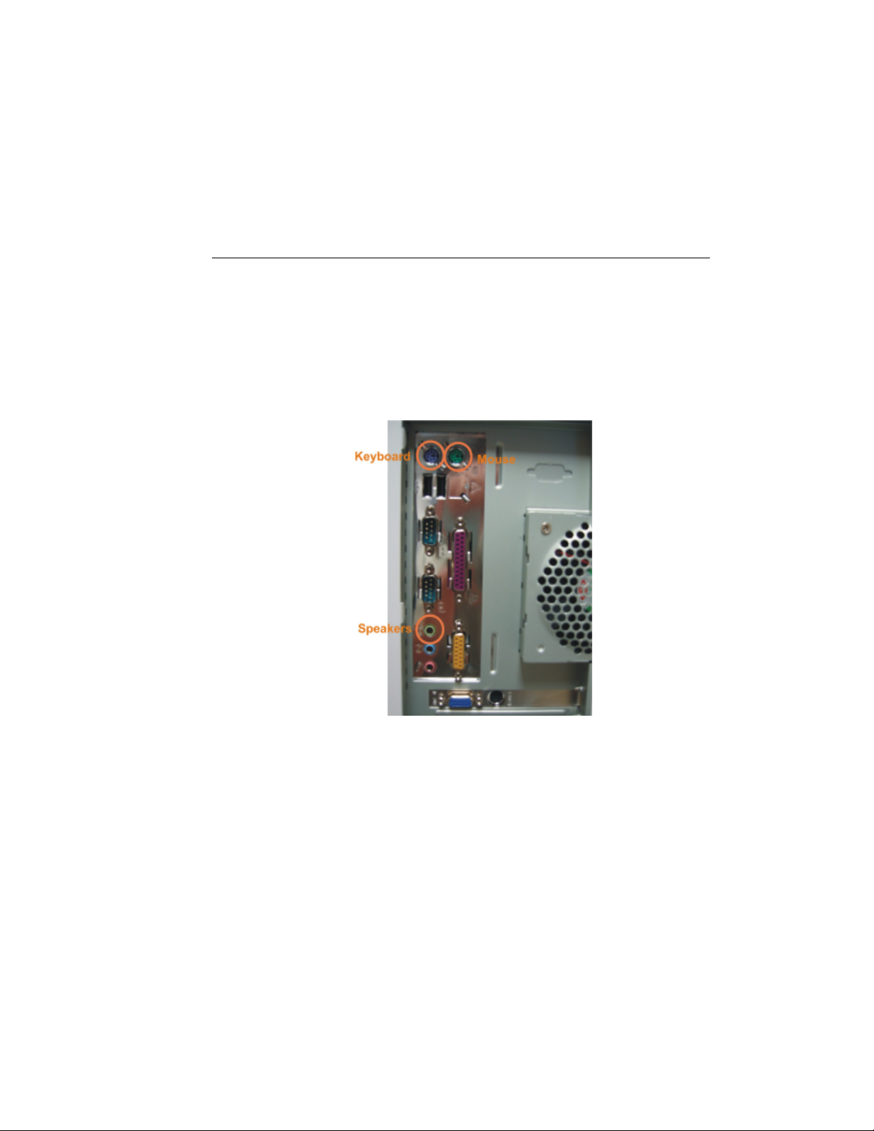
The picture below is an enlarged view of the back I/O connectors.
The keyboard, mouse, and speakers connectors are color coded for your reference.
Simply connect your keyboard to the purple keyboard connector, and your mouse to
the green mouse connector.
Next, connect your speakers to the light-green connector; this is assuming you are
using the onboard audio. If you have an add-on audio card, please consult the
manual for the location of the speakers connector.
Page 8
8 PREMIO System Manual
Connecting Your Monitor
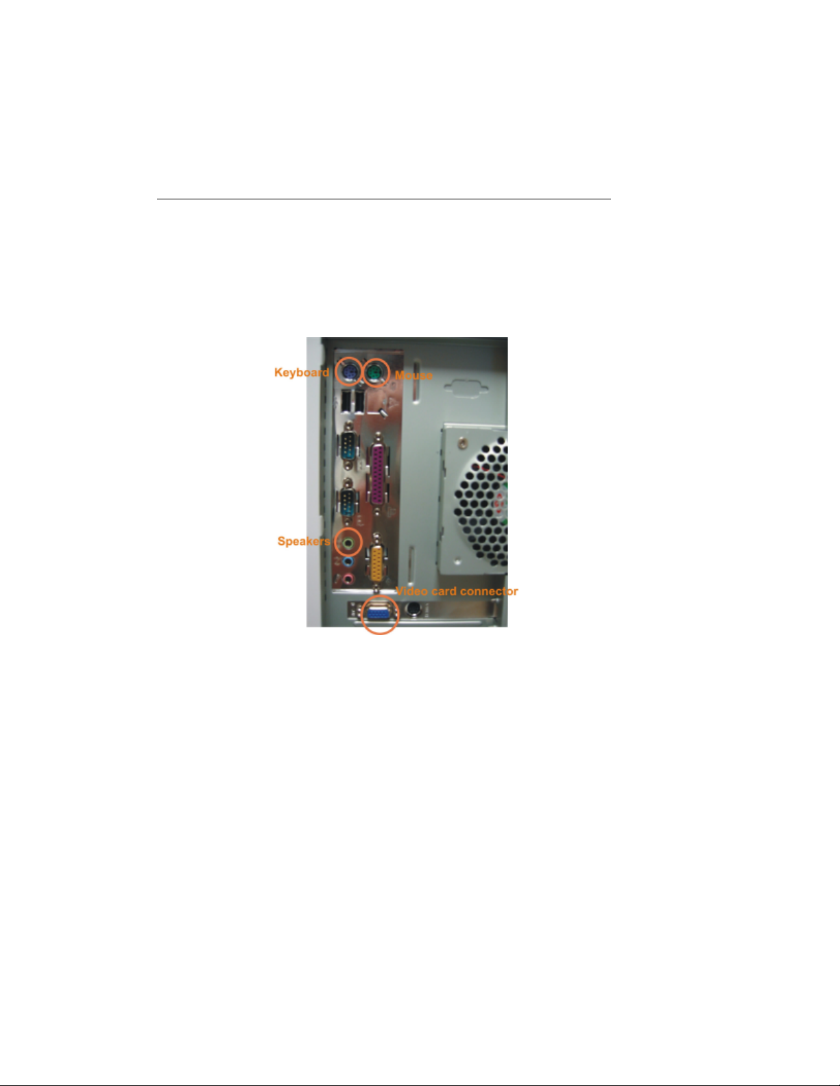
The next step is to connect your monitor to your video card. See picture below for the
location of the video card connector.
Once everything is connected, you can now turn on your monitor and system. See the
next page for the location of the midtower’s power switch.
Page 9
9 PREMIO System Manual
Switches and Indicators
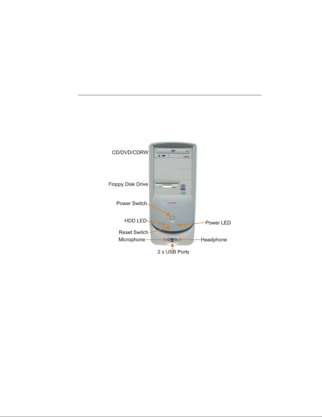
The system unit’s front panel provides access to the CD-ROM, DVD-ROM, or CDRW and floppy drives, and to the system’s switches and indicator LEDs.
n The CD/DVD/CDRW drive reads information on CDs or DVDs
n The floppy disk drive reads and writes data to 3.5” 1.44MB floppy disks
n The power switch turns the system on and off
n The hard disk drive (HDD) LED lights when the HDD is in use
n The power LED lights when the system is on
n The reset switch restarts the system in the event of a hardware lockup
n The microphone connector allows you to connect a microphone for audio input
n The headphone connector allows you to connect a standard headphone
n The USB ports allows you to connect USB devices such as printers, digital
cameras, scanners, etc.
Page 10

10 PREMIO System Manual
Upgrading
You can upgrade your PREMIO system with:
n Expansion cards
n Additional system memory
n Additional hard disk drive
To install an upgrade, you must open the system unit. Before proceeding, read the
important cautionary note below. Then follow the steps on the next page.
Caution! Static discharge can cause permanent damage to internal electronic
components of your computer. Always use the following precautions when working
inside the system unit:
n Avoid working in an area with carpeted floor
n Touch the back of the midtower’s power supply first
n Wear a grounding wrist strap (available at most electronics stores)
when handling electronic components
n Do not remove a component from its antistatic packaging until you are
ready to install it
Page 11
11 PREMIO System Manual
Opening the System Unit
Note Opening the system unit could affect your warranty. Check with the dealer
where you purchased your system before opening the system unit.
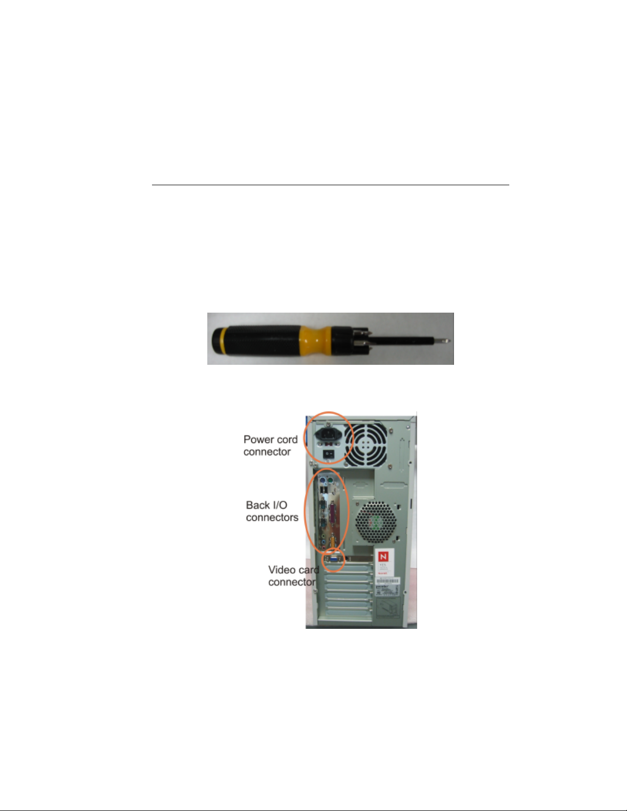
To open the system unit, you will need a standard philips (the cross head, not the flat
head) screwdriver:
Turn off the system and unplug the power cord from the power cord connector (see
picture below):
Page 12
12 PREMIO System Manual
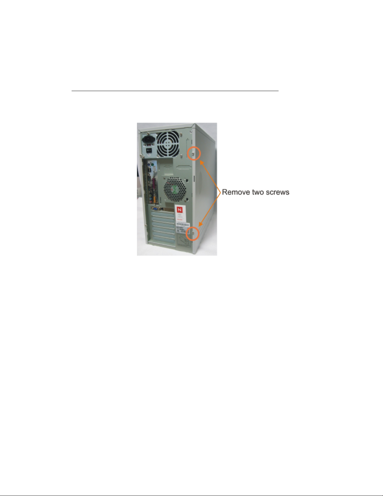
Next, using the screwdriver, remove the two screws as shown in the picture below.
Once the two screws are removed, you can simply slide the side cover off by pulling it
towards you.
Page 13

13 PREMIO System Manual
Closing the System Unit
To close the unit, slide the side panel back on and reinstall the two screws.
Page 14
14 PREMIO System Manual
Installing an Expansion Card
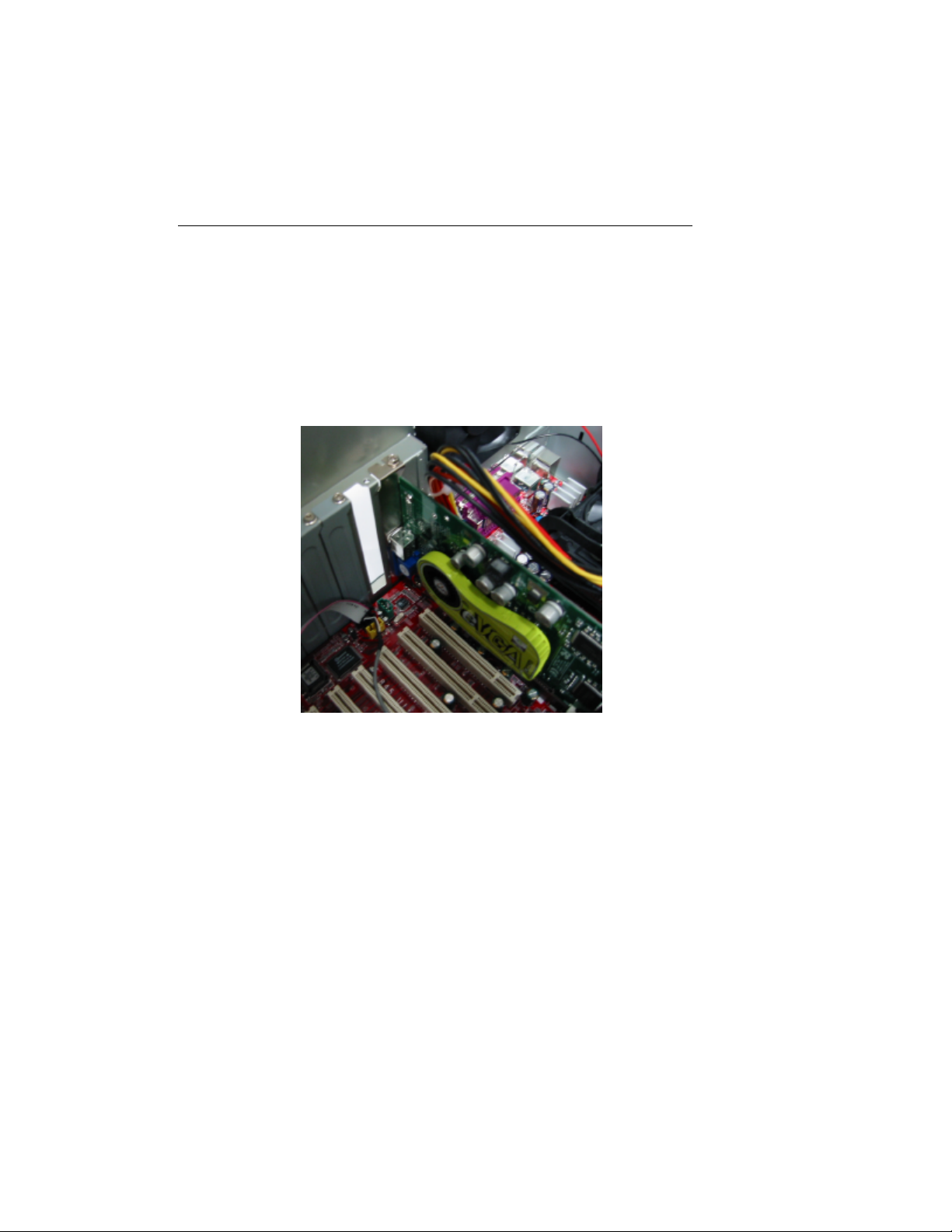
To install an expansion card, open the system unit as described on the previous page.
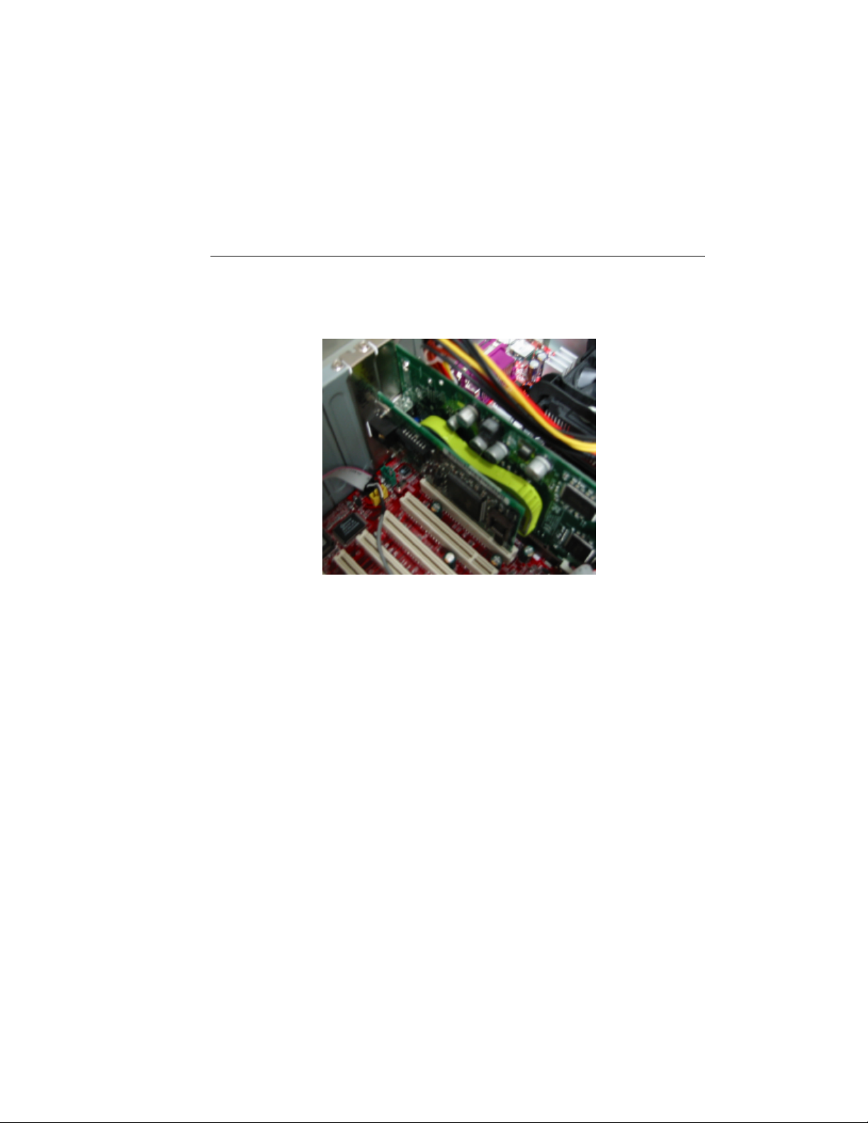
Next, remove the screw securing the slot bracket cover for the expansion slot you
want to use. Then remove the slot bracket and install your expansion card. Save the
screw to secure the expansion card later. You should also keep the slot bracket, in
case you wish to remove the expansion card later in then future.
Page 15
15 PREMIO System Manual
Insert the expansion card firmly into the slot, making sure it is seated completely.
Then install the screw onto the expansion card.
Page 16

16 PREMIO System Manual
Installing Additional Memory
For details on memory configuration, including the placement and type of memory to
use in your system, please refer to the motherboard user’s manual that came with your
system.
Page 17

17 PREMIO System Manual
Installing an Additional Hard Disk Drive
To install an additional hard disk drive in your system, follow these steps:
Disconnect the hard drive cable and power connector.
Remove the two screws securing the drive bay.
Slide the bay toward the rear of the system unit to remove it.
Insert the new drive into an open position in the bay and secure it with four screws.
Slide the bay back into the system unit and secure it with two screws.
Connect the cables.
Page 18

18 PREMIO System Manual
Getting Help
Troubleshooting
Your PREMIO system is designed to provide years of trouble-free
performance. If you have a problem with your system, first check the
information in this section for a quick solution.
Monitor Does Not Work
If your monitor appears not to be working properly:
Check that the monitor’s power cable is securely attached to the monitor and
to an outlet that is receiving power.
Check that the monitor’s video cable is securely attached to the monitor and
to the system unit’s video card connector.
Check that the monitor’s power switch is on.
Adjust the monitor’s brightness and contrast controls.
If possible, substitute another monitor that is in good working order. If the
substitute works, your monitor may need repair or replacement.
Page 19
19 PREMIO System Manual
Keyboard Does Not Work
If the NumLock indicator in the upper right corner of the keyboard does not
light when the system powers up, or the keyboard does not work:
Check that the keyboard cable is securely attached to the system unit’s
keyboard connector.
If possible, substitute another keyboard that is in good working order. If the
substitute works, your keyboard may need replacement.
Mouse Does Not Work
If your mouse pointer does not move or moves erratically when you move
the mouse:
Check that the mouse cable is securely attached to the mouse connector on
the system unit.
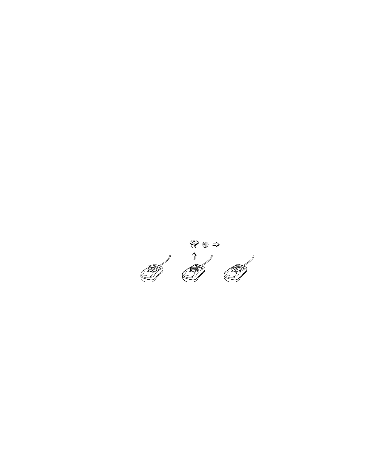
Disassemble the mouse and clean the roller ball. (This does not apply if you
have an optical mouse.)
Page 20

20 PREMIO System Manual
System Unit Problems
The fan inside the system unit should make a low, steady sound when operating
properly. If the fan is totally silent:
§ Check that the system power cord is securely attached to the back of
the system unit and to a power outlet. Verify that the outlet has
power.
§ If possible, substitute another power cord that is in good working
order. If the substitute works, replace your power cord.
§ If the fan makes excessive noise:
§ Turn off the system, open the system unit case, and inspect the fan
for any obstructions.
§ Turn on the system and listen closely to the fan. If the noise comes
from inside the fan housing, your power supply may need
replacement.
Hard Disk Problems
Your hard disk should make a slight whirring sound when operating properly. If the
disk is totally silent:
§ Turn off the system, open the system unit case, and check that the
power cable between the power supply and the hard disk is securely
attached at both ends. If it is, your hard disk may be defective.
§ If the hard disk makes excessive noise:
§ Turn off the system, open the system unit case, and remove the hard
disk power cable connector from the hard disk. Then turn the
system back on. If the noise disappears, your hard disk may be
defective.
Warranty Service
If you have a problem with your PREMIO system that requires
service during the warranty period, contact the dealer where
you purchased your system. Your dealer will try to resolve the
problem for you. If your dealer cannot resolve the problem, you
can contact PREMIO directly at the address below.
Note To obtain warranty service, you must provide proof of
purchase, including the purchase date.
Page 21

21 PREMIO System Manual
Technical Support
You can contact PREMIO technical support at the following
address:
Premio Computer, Inc.
918 Radecki Court
City of Industry, CA 91748
Telephone: 800-568-6388
Fax: 626-839-3191
Email: [email protected]
PREMIO on the Internet
PREMIO maintains a web page on the Internet with the latest
information on PREMIO products, updated drivers, answers to
common problems, an extensive component troubleshooting
guide, and more. Visit our web page at:
http://www.premiopc.com
Page 22

Appendix
Limited 3-Year Warranty
Premio Computer, Inc. warrants its line of PREMIO® computer systems
(hereinafter “Product”) to be free from defects in material and
workmanship for a period of three (3) years from the date of original
purchase from Premio Computer, Inc. or a Premio Computer, Inc.
authorized reseller. This warranty does not cover monitor and LCD
panels, nor third-party hardware and software which has a separate
manufacturer’s warranty. Warranty for such third-party hardware and
software, if any, is subject to the third-party’s warranty policy.
PREMIO branded monitors are warranted as follows:
Three (3) year parts and labor except for CRT
One (1) year parts and labor for CRT
PREMIO branded LCD panels are warranted as follows:
One (1) year parts and labor
SERVICE UNDER WARRANTY
If this Product fails to be in good working order during this 3year warranty period (or specific period of time as noted
above), Premio Computer, Inc. will, at its option, repair or
replace the Product. Repair parts and/or replacement Products
may be either new or reconditioned at Premio Computer Inc.’s
discretion. The limited warranty does not include service to
repair damage from improper installation, abuse or
modifications to the Product not approved in writing by Premio
Computer, Inc. Any service repair outside the scope of this
limited warranty shall be at Premio Computer, Inc.’s or its
Authorized Service Provider’s rates and terms in effect.
This warranty is valid only within the United States and applies only
to Products which are new and in cartons which are unopened on the
date of purchase.
EXCLUSIONS FROM PREMIO, INC. LIMITED
WARRANTY PROGRAM
ALL OTHER EXPRESSED AND IMPLIED WARRANTIES FOR
THIS PRODUCT, INCLUDING THE WARRANTIES OF
MERCHANTABILITY AND FITNESS FOR A PARTICULAR
PURPOSE, ARE HEREBY DISCLAIMED. IF THIS PRODUCT IS
NOT IN GOOD WORKING ORDER AS WARRANTED ABOVE,
PREMIO COMPUTER, INC.'S SOLE AND EXCLUSIVE REMEDY
SHALL BE REPAIR OR REPLACEMENT AS STATED ABOVE.
Page 23

23 PREMIO System Manual
IN NO EVENT WILL PREMIO COMPUTER, INC. BE LIABLE TO
THE CUSTOMER OR ANY THIRD PARTY FOR ANY
DAMEAGES IN EXCESS OF THE PURCHASE PRICE OF THE
PRODUCT. THIS LIMITATION APPLIES TO DAMAGES OF ANY
KIND INCLUDING ANY DIRECT OR INDIRECT DAMAGES,
LOST PROFITS, LOST SAVINGS OR OTHER SPECIAL,
INCIDENTAL, EXEMPLARY OR CONSEQUENTIAL DAMAGES
WETHER ARISING OUT OF THE USE OF OR INABILITY TO
USE SUCH PRODUCT, EVEN IF PREMIO COMPUTER, INC. OR
AN AUTHORIZED PREMIO COMPUTER, INC.
REPRESENTATIVE OR DEALER HAS BEEN ADVISED OF THE
POSSIBILITY OF SUCH DAMAGES OR OF ANY CLAIM BY
ANY OTHER PARTY. SOME STATES DO NOT ALLOW THE
EXCLUSION OR LIMITATION OF INCIDENTAL OR
CONSEQUENTIAL DAMAGES FOR SOME PRODUCTS, SO THE
ABOVE LIMITATIONS OR EXCLUSIONS MAY NOT APPLY TO
YOU. PREMIO COMPUTER, INC. AUTHORIZED RESELLERS
AND SERVICE PROVIDERS/PARTNERS MAY BE CHANGED,
ADDED OR DELETED, WITHOUT NOTICE OR LIABILITY.
PREMIO COMPUTER, INC. DISCLAIMS ANY AUTHORIZED
RESELLERS AND SERVICE PROVIDER/PARTNER TO THE
PROGRAM. THIS WARRANTY GIVES YOU SPECIFIC LEGAL
RIGHTS AND YOU MAY ALSO HAVE OTHER RIGHTS WHICH
MAY VARY FROM STATE TO STATE.
Page 24

FCC Standards
The FCC (Federal Communications Commission) restricts the amount of radiation
and radio frequency emissions from computing equipment.
This equipment generates and uses radio frequency energy and if not installed and
used properly in strict accordance with the operation instructions, reference manuals,
and the service manual, may cause interference to radio or television reception.
This equipment can be tested and found to comply with the limits for a Class B digital
device pursuant to part 15 of the FCC rules. There limits are designed to provide
reasonable protection against harmful interference in a residential installation. This
equipment generates, uses, and can radiate radio frequency energy and, if not installed
and used in accordance with the instructions, may cause harmful interference to radio
communications. However, there is no guarantee that interference will not occur in a
particular installation. If this equipment does cause harmful interference to radio or
television reception, which can be determined by turning the equipment off and on,
then the user is encouraged to try to correct the interference by one or more of the
following procedures:
§ Reorient or relocate the receiving antenna
§ Increase the separation between the equipment and receiver
§ Connect the equipment into an outlet on a circuit different from that
to which the receiver is connected
§ Consult the dealer or an experienced radio/TV technician for help
Page 25

25 PREMIO System Manual
Important Safety Instructions
These instructions are provided by Underwriters Laboratories, Inc.
1. Read all of these instructions and save them for later reference.
2. Follow all warnings and instructions marked on the product.
3. Unplug this product from the wall outlet before cleaning. Do not
use liquid or aerosol cleaners. Use a damp cloth for cleaning.
4. Do not use this product near water.
5. Do not place this product on an unstable cart, stand or table. The
product may fall, causing serious damage to the product.
6. Slots and openings on the cabinet and the back or bottom are
provided for ventilation. To ensure reliable operation of the
product and to protect it from overheating, do not block or cover
these openings. The openings should never be blocked by placing
the product on a bed, sofa, rug or other similar surface. This
product should never be placed near or over a radiator or heat
register. This product should not be placed in a built-in
installation unless proper ventilation is provided.
7. This product should be operated from the type of power source
indicated on the marking label. If you are not sure of the type of
power available, consult your dealer or local power company.
8. This product is equipped with a 3-wire grounding-type plug, a
plug having a third (grounding) pin. This plug will only fit into a
grounding-type power outlet. This is a safety feature. If you are
unable to insert the plug into the outlet, contact your electrician to
replace your obsolete outlet. Do not defeat the safety purpose of
the grounding-type plug.
9. Do not allow anything to rest on the power cord. Do not locate
this product where the cord will be walked on.
10. If an extension cord is used with this product, make sure that the
total of the ampere ratings on the products plugged into the
extension cord do not exceed the extension cord ampere rating.
Also, make sure that the total of all products plugged into the wall
outlet does not exceed 15 amperes.
11. Never push objects of any kind into this product through cabinet
slots as they may touch dangerous voltage points or short out
parts that could result in a risk of fire or electric shock. Never
spill liquid of any kind on the product.
12. Except as explained elsewhere in this manual, don't attempt to
service this product yourself. Opening and removing those covers
that are marked “Do Not Remove” may expose you to dangerous
Page 26

voltage points or other risks. Refer all servicing on those
compartments to service personnel.
13. Unplug this product from the wall outlet and refer servicing to
qualified service personnel under the following conditions:
A. When the power cord or plug is damaged or frayed.
B. If liquid has been spilled into the product.
C. If the product has been exposed to rain or water.
D. If the product does not operate normally when the operating
instructions are followed. Adjust only those controls that are
covered by the operating instructions since improper
adjustment of other controls may result in damage and will
often require extensive work by a qualified technician to
restore the product to normal operation.
E. If the product has been dropped or the cabinet has been
damaged.
F. If the product exhibits a distinct change in
performance, indicating a need for service.
Page 27
MSI
MICRO-STAR INTERNATIONAL
MS-6545 (v2.X) ATX Mainboard
850E Max
Version 2.0
G52-MA6545X1
i
Page 28
Manual Rev: 2.0
Release Date: July 2002
FCC-B Radio Frequency Interference Statement
This equipment has been tested and found to comply with the limits for a class
B digital device, pursuant to part 15 of the FCC rules. These limits are designed
to provide reasonable protection against harmful interference when the equipment is operated in a commercial environment. This equipment generates, uses
and can radiate radio frequency energy and, if not installed and used in accordance with the instruction manual, may cause harmful interference to radio
communications. Operation of this equipment in a residential area is likely to
cause harmful interference, in which case the user will be required to correct
the interference at his own expense.
Notice 1
The changes or modifications not expressly approved by the party responsible for compliance could void the user’s authority to operate the equipment.
Notice 2
Shielded interface cables and A.C. power cord, if any, must be used in order to
comply with the emission limits.
VOIR LA NOTICE D’INSTALLA TION AVANT DE RACCORDER AU
RESEAU.
Micro-Star International MS-6545
T ested to comply
with FCC Standard
For Home or Office Use
ii
Page 29

Edition
July 2002
Copyright Notice
The material in this document is the intellectual property of MICRO-STAR
INTERNATIONAL. We take every care in the preparation of this document,
but no guarantee is given as to the correctness of its contents. Our products
are under continual improvement and we reserve the right to make changes
without notice.
Trademarks
All trademarks are the properties of their respective owners.
Intel® and Pentium® are registered trademarks of Intel Corporation.
PS/2 and OS®/2 are registered trademarks of International Business Machines
Corporation.
Windows® 95/98/2000/NT/XP are registered trademarks of Microsoft
Corporation.
Netware® is a registered trademark of Novell, Inc.
Award® is a registered trademark of Phoenix T echnologies Ltd.
AMI® is a registered trademark of American Megatrends Inc.
Revision History
Revision Revision History Date
V2.0 First release for PCB 2.X July 2002
iii
Page 30

Safety Instructions
1. Always read the safety instructions carefully.
2. Keep this User’s Manual for future reference.
3. Keep this equipment away from humidity.
4. Lay this equipment on a reliable flat surface before setting it up.
5. The openings on the enclosure are for air convection hence protects the
equipment from overheating. DO NOT COVER THE OPENINGS.
6. Make sure the voltage of the power source and adjust properly 110/220V
before connecting the equipment to the power inlet.
7. Place the power cord such a way that people can not step on it. Do not
place anything over the power cord.
8. Always Unplug the Power Cord before inserting any add-on card or module.
9. All cautions and warnings on the equipment should be noted.
10. Never pour any liquid into the opening that could damage or cause electrical shock.
11. If any of the following situations arises, get the equipment checked by a
service personnel:
z The power cord or plug is damaged.
z Liquid has penetrated into the equipment.
z The equipment has been exposed to moisture.
z The equipment has not work well or you can not get it work according
to User’s Manual.
z The equipment has dropped and damaged.
z The equipment has obvious sign of breakage.
12. DO NOT LEAVE THIS EQUIPMENT IN AN ENVIRONMENT
UNCONDITIONED, STORAGE TEMPERA TURE ABOVE 600 C (1400F), IT
MA Y DAMAGE THE EQUIPMENT.
CAUTION: Danger of explosion if battery is incorrectly replaced.
Replace only with the same or equivalent type recommended by the
manufacturer.
iv
Page 31

CONTENTS
Getting Started .......................................................................................... 1-1
Mainboard Specification ......................................................................1-3
Mainboard Layout ...............................................................................1-5
Quick Components Guide .................................................................... 1-5
Key Features ........................................................................................1-7
MSI Special Features ........................................................................... 1-7
T .O.P T ech™ ................................................................................. 1-7
Fuzzy Logic™ 4 ............................................................................. 1-8
PC Alert™ III ................................................................................. 1-8
Live BIOS™/Live Driver™ .......................................................... 1-10
Live Monitor™ ............................................................................ 1-11
D-Bracket™ 2 (Optional) ............................................................. 1-12
Chapter 2. Hardware Setup ...................................................................... 2-1
CPU Installation Procedures for Socket 478 .................................. 2-2
Installing the CPU Fan .................................................................. 2-3
CPU Core Speed Derivation Procedure .........................................2-5
Memory Installation ............................................................................. 2-5
Memory Population Rules............................................................. 2-5
Installing RIMM Modules ............................................................ 2-7
Power Supply ....................................................................................... 2-7
A TX 20-Pin Power Connector: JPWR1..........................................2-7
A TX 12V Power Connector: JPWR3.............................................. 2- 9
A TX 5V/3V Power Connector: JPWR2 ..........................................2-9
Back Panel ............................................................................................ 2-9
Mouse Connector: JKBMS1 ......................................................... 2-9
Keyboard Connector: JKBMS1 ................................................... 2-10
USB 1.1 Connectors .................................................................... 2-10
Serial Port Connector: COM A & COM B ................................... 2-11
Audio Port Connectors ............................................................... 2-11
v
Page 32

Parallel Port Connector: LPT1...................................................... 2-12
Connectors......................................................................................... 2-13
Floppy Disk Drive Connector: FDD1........................................... 2-13
Hard Disk Connectors: IDE1 & IDE2 ........................................... 2-15
Front Panel Connector: JFP1 and JFP2 (Optional Intel spec) ...... 2-15
Fan Power Connectors: CPUF AN/SYSF AN/PSF AN ................... 2-16
Front Panel Audio Connector: JAUD1 (Optional Intel spec) ...... 2-17
Bluetooth Connector: JBT1 (Optional) ........................................ 2-18
W ake On Ring Connector: JWR1 ................................................ 2-19
IrDA Infrared Module Connector: JIR1 ....................................... 2-20
Chassis Intrusion Switch Connector: JCI1 .................................. 2-20
Remote Power On/Off Switch Connector: JRMS1 ....................... 2-21
Power Saving Switch Connector: JGS1........................................ 2-21
Front USB 2.0 Connectors: JUSB1 & JUSB2 (Optional) .............. 2-22
D-Bracket™ 2 Connector: JDB1 .................................................. 2-24
Jumpers .............................................................................................. 2-25
Clear CMOS Jumper: JBA T1........................................................ 2-25
Clear BIOS Password Jumper: J6 ................................................. 2-26
BIOS Flash Jumper: J5 ................................................................. 2-26
LAN Enable/Disable Jumper: J2 .................................................. 2-27
RDRAM Over V oltage Jumper: J1................................................ 2-28
PCI Interrupt Request Routing .................................................... 2-30
Chapter 3. A WARD® BIOS Setup............................................................ 3-1
Entering Setup...................................................................................... 3-3
Control Keys ........................................................................................ 3-3
Getting Help ......................................................................................... 3-3
The Main Menu ................................................................................... 3-5
Standard CMOS Features .................................................................... 3-7
Advanced BIOS Features .................................................................... 3- 9
Advanced Chipset Features............................................................... 3-13
vi
Page 33

Integrated Peripherals ........................................................................ 3-15
Power Management Setup ................................................................. 3-19
PNP/PCI Configurations..................................................................... 3-23
PC Health Status ................................................................................ 3-25
Frequency/Voltage Control ................................................................ 3-27
High System Performance .................................................................. 3-29
Load Optimized Defaults .................................................................... 3-29
Set Supervisor/User Password........................................................... 3-31
Save & Exit Setup............................................................................... 3-33
Exit Without Saving ........................................................................... 3-33
Appendix A. Using 4-/6-channel Audio Function .....................................A-1
Installing C-Media Drivers ..................................................................A-2
Hardware Configuration ......................................................................A-2
Software Configuration .......................................................................A-3
Glossary ....................................................................................................G-1
vii
Page 34

Introduction
Getting Started
The 850 E Max (MS-6545 v2.X) ATX mainboard is a high-performance
computer mainboard based on Intel® 850E chipset. It is optimized to support
Intel® Pentium® 4 processors for high-end business/personal desktop markets,
and it is a highly-flexible chipset which is designed to extend the basic graphics/
multimedia PC platform up to the mainstream performance desktop platform.
TOPICS
Mainboard Specification 1-2
Mainboard Layout 1-4
Quick Components Guide 1-5
Key Features 1-6
MSI Special Features 1-7
1
1-1
Page 35

Chapter 1
Mainboard Specification
CPU
Supports Intel® Pentium® 4 (Willameete/Northwood) processor in the 478
pin package.
Supports from 1.6GHz to 2.53GHz and up.
Chipset
Intel® 850E
- Supports Direct RDRAM up to 2GB maximum memory.
- Supports System bus at 100/133 HMz (400/533 MHz System bus).
- 1.5V AGP interface with 4x data transfer and 4x fast write capability.
Intel® ICH2
- Upstream hub interface for access to the Intel MCH.
- 2-channel Ultra ATA 100 Bus Master IDE controller.
- USB controller 1.1 (expanded capabilities for 4 ports).
- I/O APIC.
- SMBus controller.
- FWH interfaceAuto enables onboard SCSI termintor
- LPC interface, AC’97 2.1 interface, PCI 2.2 interface.
- Integrated system management controller.
- Low pin count interface for SIO.
Main Memory
Supports four 184-pin gold-lead RIMM sockets.
Supports a maximum memory size of 2GB.
Slots
One AGP (Accelerated Graphics Port) 4x slot.
Four 32-bit/33 MHz PCI bus slots.
Support 3.3v/5v PCI bus interface.
One CNR (Communication Network Riser) slot.
On-Board IDE
An IDE controller on the Intel® ICH2 chipset provides IDE HDD/CD-ROM
with PIO, Bus Master and Ultra DMA 100 operation modes.
Can connect up to four IDE devices.
On-Board Peripherals
Intergrated Super I/O Controller
- 1 floppy port supports 2 FDDs with 360K, 720K, 1.2M, 1.44M and
1-2
Page 36

Introduction
2.88Mbytes.
- 2 serial ports (COM A + COM B).
- 1 parallel port supports SPP/EPP/ECP mode.
- 1 IrDA connector for SIR.
- 1 Line-in/Line-out/Mic-in port.
- 1 RJ45 connector.
USB Interface
4 USB 1.1 ports (Rear * 4, one for BlueTooth Networking function) and 4
NEC USB 2.0 ports (Front * 4) (Optional)
Audio
C-Media CMI8738/PCI-6ch-LX supports 2/4/6 ch speaker
- 6CH DAC for AC3® 5.1CH purpose.
- HRTF-based 3D positional audio, supporting DirectSoundTM 3D and A3D
interface.
- Supports 4.1/5.1 speakers, C3DX positional audio in 4/6 CH speaker mode.
- Legacy audio SBPROTM compatible.
- DLS-based wavetable music synthesizer.
Intel® LAN (Optional)
Intel® 82562ET chip
- Integrated Fast Ethernet MAC and PHY in one chip.
- Supports 10 Mb/s and 100 Mb/s.
- Compliance with PCI v2.2.
- Supports ACPI Power Management.
TM
BIOS
The mainboard BIOS provides “Plug & Play” BIOS which detects the peripheral devices and expansion cards of the board automatically.
IDE drive auto configure, Advanced Power Management (APM) 1.2, ACPI
1.0a, DMI 2.0, ECC/Parity support, LS 120 support, PnP 1.0a, SMBIOS 2.3,
WFM 2.0, Auto enables onboard SCSI termintor.
Supports boot from Lan and boot from USB device.
Dimension
ATX Form Factor: 305 mm (L) x 244 mm (W) x 4 layers PCB.
Mounting
12 mounting holes.
1-3
Page 37

Chapter 1
Mainboard Layout
Top : mou se
Bottom: keyboard
USB
ports
Top : Par alle l Port
Bottom:
COM A
COM B
Top: LAN Jack
Bottom: USB
ports
Line-Out
Line-In
Mic
JCD1
CPUFAN
JPWR3
Intel
850E
RIMM1
JPWR2
PSFAN
y
l
p
p
u
X
J1
3
2
M
M
I
R
4
M
M
M
M
I
I
R
R
S
T
r
A
e
w
o
P
1
2
E
E
D
D
I
I
1
D
D
F
J2
PCI Slot 1
PCI Slot 2
PCI Slot 3
PCI Slot 4
AGP Slot
BIOS
NEC
D720100AS1
JAUD1JBT1
JDB1
Winbond
W83627HF-AW
8
3
7
8
I
M
C
JCI1
JIR1
CNR
850 E Max (MS-6545 v2.X) ATX Mainboard
1-4
BATT
+
JFP2
JGS1
JBAT1
SYSFAN
JWR1
JRMS1
JFP1
ICH2
J6
J5
JUSB2
JUSB1
Page 38

Quick Components Guide
Component Function Reference
JPWR1/2/3 ATX power connectors See p. 2-7
JKBMS1 Mouse/keyboard connectors See p. 2-9
USB 1.1 Connectors Connecting to USB devices See p. 2-10
COM A & COM B Serial port connector See p. 2-11
LPT1 Parallel port connector See p. 2-12
FDD1 Floppy disk drive connector See p. 2-13
IDE1& IDE2 Hard disk connectors See p. 2-14
JFP1 & JFP2 Front panel connectors See p. 2-15
CPU/SYS/PS FAN Fan power connectors See p. 2-16
JAUD1 Front panel audio connector See p. 2-17
JBAT1 Bluetooth connector See p. 2-18
JCD1 CD connector See p. 2-19
JWR1 Wake On Ring Connector See p. 2-19
JIR1 IrDA infrared module connector See p. 2-20
JCI1 Chassis intrusion switch connector See p. 2-20
JRMS1 Remote power on/off switch See p. 2-21
JGS1 Power saving switch connector See p. 2-21
JUSB1 & JUSB2 Front USB 2.0 Connectors See p. 2-22
JDB1 D-Bracket connector See p. 2-24
JBAT1 Clear CMOS jumper See p. 2-25
J6 Clear BIOS password jumper See p. 2-26
J5 BIOS flash jumper See p. 2-26
J2 LAN Enable/Disable Jumper See p. 2-27
J1 RDRAM Over Voltage Jumper See p. 2-28
AGP Slot Connecting to AGP cards See p. 2-30
PCI Slots Connecting to expansion cards See p. 2-30
CNR Slot Connecting to expansion cards See p. 2-30
Introduction
1-5
Page 39

Chapter 1
Key Features
z ATX Form Factor
z CPU: Intel
®
Pentium® 4 processor in the 478 pin package
z USB PC to PC networking function (Optional)
z Fuzzy Logic 4
z Live BIOS / Live Driver
z PC Alert™ III system hardware monitor
z D-LED/ D-Bracket (Optional)
z LAN/Modem Ring Wake Up Function
z Suspend to RAM/Disk
z PC2001 Compliant
z STD/STR (S3/S4)
z Chassis intrusion
1-6
Page 40
Introduction
MSI Special Features
T.O.P Tech™
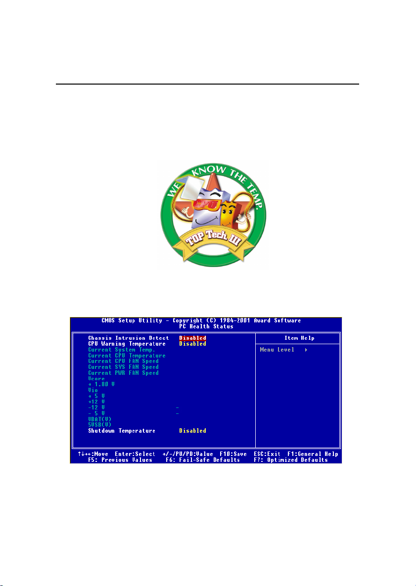
The T.O.P TechTM is an extended sensing device that can 100% accurately detect the CPU’s temperature. You can find out the temperature on BIOS
setup menu. The PC AlertTM also provides the information.
CPU temperature on Setup menu
1-7
Page 41
Chapter 1
Fuzzy Logic™ 4
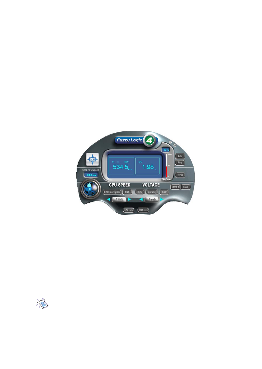
The Fuzzy Logic™ 4 utility is a user friendly tool that allows users to
view and adjust the current system status. To overclock the CPU FSB (Front
Side Bus) frequency under the Windows operating system, click FSB and use
the right and left arrow keys to select the desired FSB, and then click Apply to
apply the new setup value. To enable the system running at the specified FSB
every time when you click Turbo, click Save to save the desired FSB first. If
you want to know the maximal CPU overclocking value, click Auto to start
testing. The CPU FSB will automatically increase the testing value until the PC
reboots. After rebooting, click Turbo to apply the test result. Click Default to
restore the default values.
Features:
z MSI Logo links to the MSI Web site
z CPU Speed allows users to adjust the CPU speed through CPU
Multiplier and FSB
z Voltage allows user to adjust the voltage of CPU/Memory/AGP
z MSI Info provides information about the mainboard, BIOS and OS
z CPU Info provides detailed information about the CPU
z CPU Fan Speed shows the current running speed of CPU Fan
z CPU Temp. shows the current CPU temperature
Note: To adjust the options under CPU Speed and Voltage, use the
right and left arrow keys to select the desired value and then click
Apply to run the setup value.
1-8
Page 42
Introduction
PC Alert™ III
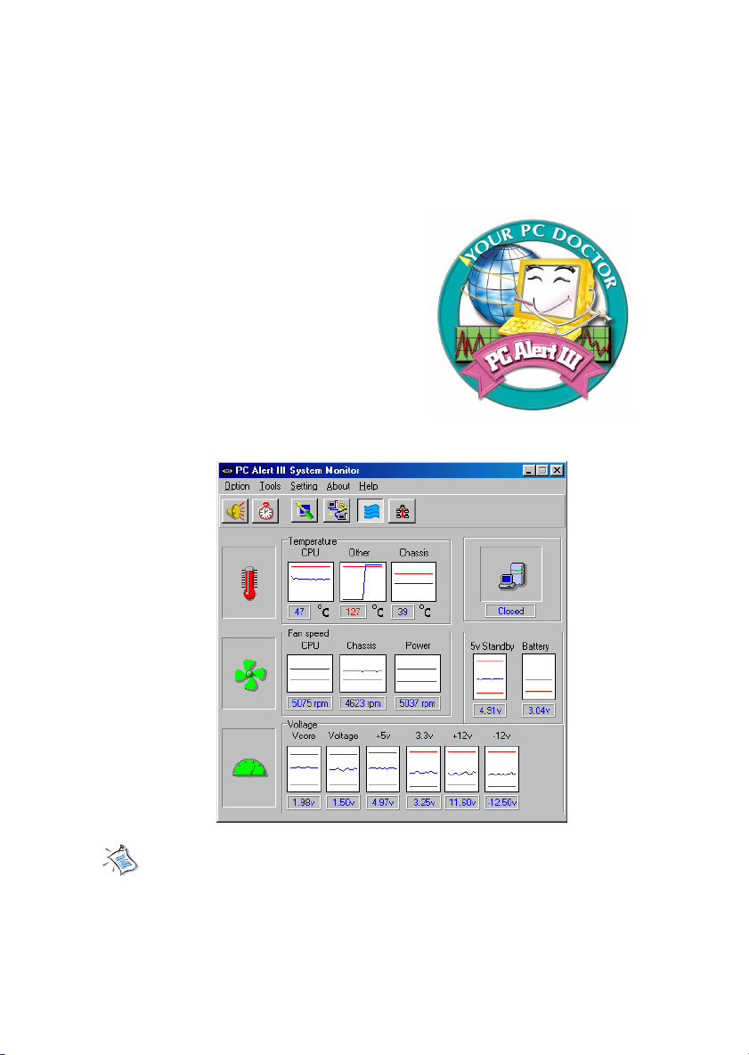
The PC AlertTM III is a utility you can find in the CD-ROM disk. The
utility is just like your PC doctor that can detect the following PC hardware
status during real time operation:
* monitor CPU & system temperatures
* monitor fan speed(s)
* monitor system voltage
* monitor chassis intrusion
If one of the items above is abnormal,
the program main screen will be immediately
shown on the screen, with the abnormal item
highlighted in red. This will continue to be
shown until users disable the warning.
Note: Items shown on PC Alert III vary depending on your system’s
status.
1-9
Page 43
Chapter 1
Live BIOS™/Live Driver™
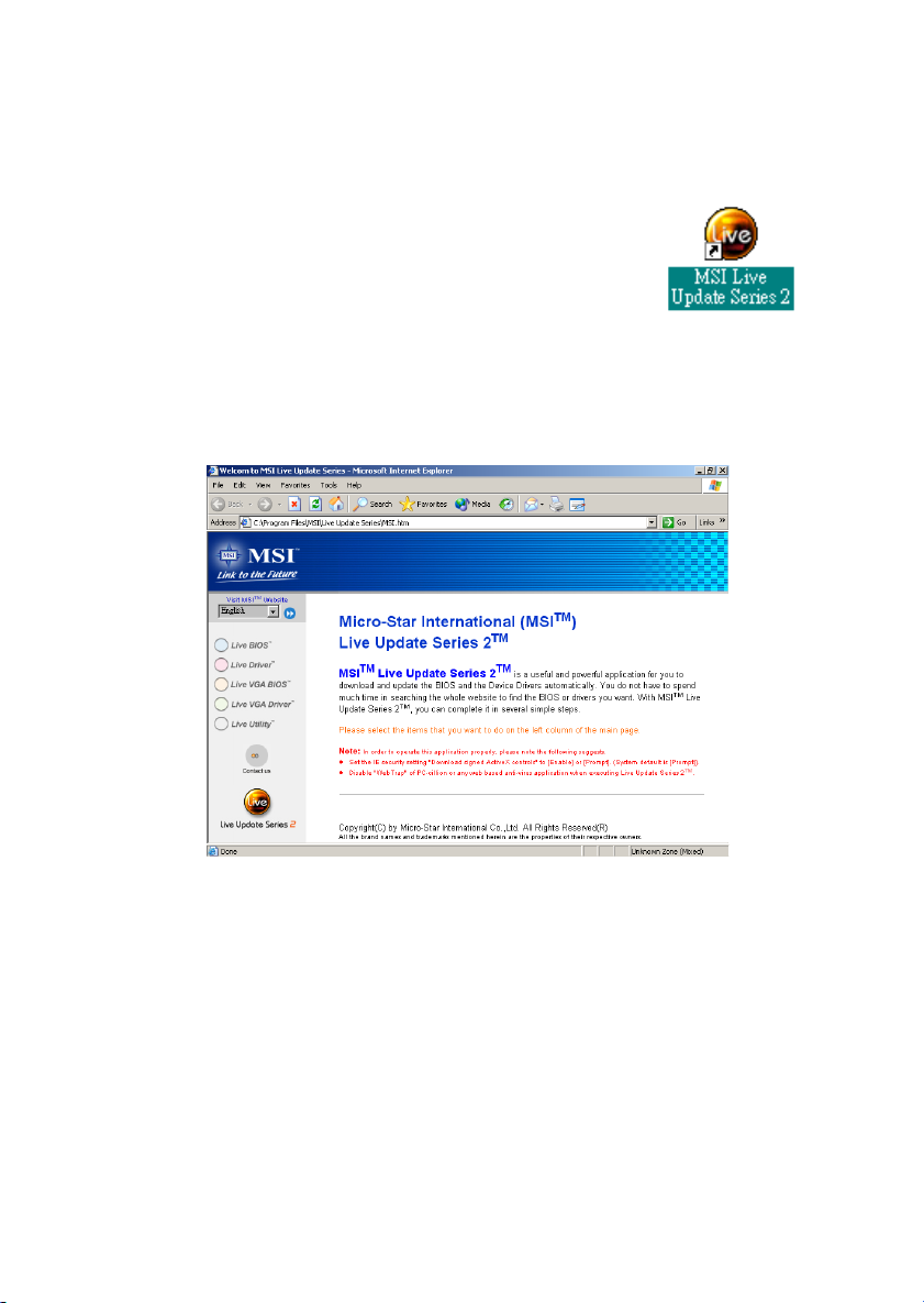
The Live BIOS™/Live Driver™ is a tool used to detect
and update your BIOS/drivers online so that you don’t need
to search for the correct BIOS/driver version throughout the
whole Web site. To use the function, you need to install the
“MSI Live Update Series 2” application. After installation, the
“MSI Live Update Series 2” icon (as shown on the right) will
appear on the screen.
Double click the “MSI Live Update Series 2” icon, and the following
screen will appear:
Five buttons are placed on the leftmost pane of the screen. Click the desired
button to start the update process.
zz
z Live BIOS – Updates the BIOS online.
zz
zz
z Live Driver – Updates the drivers online.
zz
zz
z Live VGA BIOS – Updates the VGA BIOS online.
zz
zz
z Live VGA Driver – Updates the VGA driver online.
zz
zz
z Live Utility – Updates the utilities online.
zz
If the product you purchased does not support any of the functions listed
above, a “sorry” message is displayed. For more information on the update
instructions, insert the companion CD and refer to the “Live Update Series
Guide” under the “Manual” Tab.
1-10
Page 44
Introduction
Live Monitor™
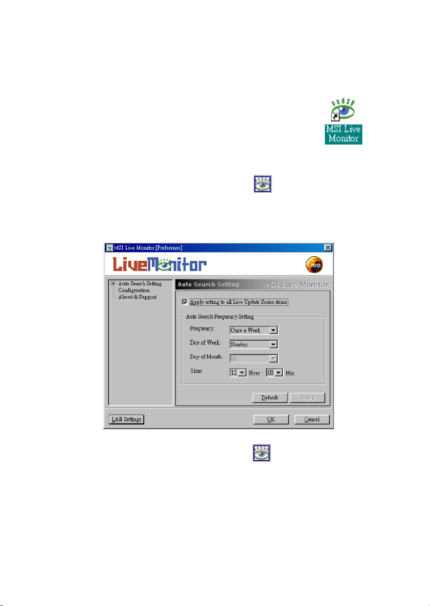
The Live Monitor™ is a tool used to schedule the search
for the latest BIOS/drivers version on the MSI Web site. To use
the function, you need to install the “MSI Live Update Series 2”
application. After the installation, the “MSI Live Monitor” icon
(as shown on the right) will appear on the screen. Double click
this icon to run the application.
Double click the “MSI Live Monitor” icon at the lower-right corner
of the taskbar, and the following dialog box will appear. You can specify how
often the system will automatically search for the BIOS/drivers version, or
change the LAN settings right from the dialog box.
You can right-click the MSI Live Monitor icon to perform the functions
listed below:
zz
z Auto Search – Searches for the BIOS/drivers version you need immediately.
zz
zz
z View Last Result – Allows you to view the last search result if there is any.
zz
zz
z Preference – Configures the Search function, including the Search schedule.
zz
zz
z Exit – Exits the Live Monitor™ application.
zz
1-11
Page 45
Chapter 1
D-Bracket™ 2 (Optional)
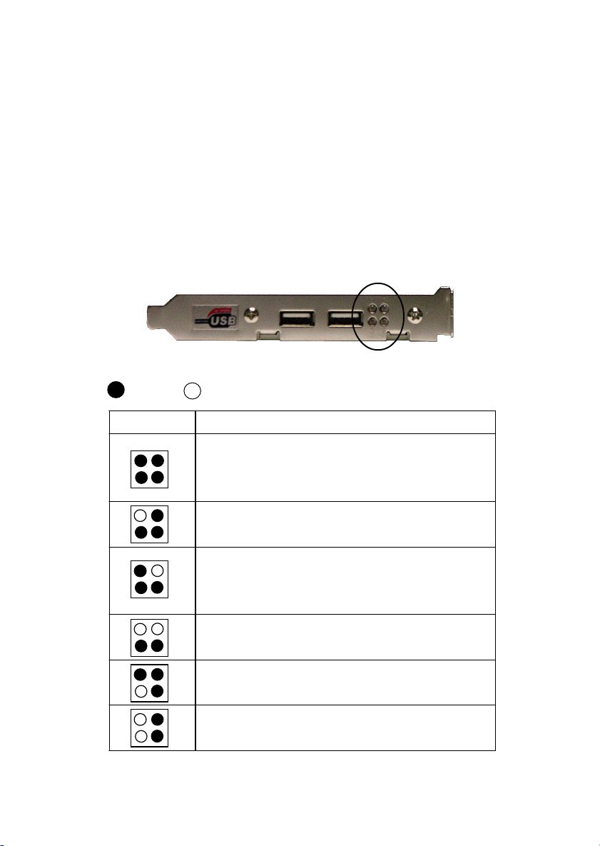
D-Bracket™ 2 is a USB bracket integrating four Diagnostic LEDs, which
use graphic signal display to help users understand their system. The LEDs
provide up to 16 combinations of signals to debug the system. The 4 LEDs can
detect all problems that fail the system, such as VGA, RAM or other failures.
This special feature is very useful for overclocking users. These users can use
the feature to detect if there are any problems or failures.
D-Bracket™ 2 supports both USB 1.1 & 2.0 spec.
D-Bracket™ 2
1 2
3 4
Red
Green
D-Bracket™ 2 Description
System Power ON
1 2
3 4
Early Chipset Initialization
Memory Detection Test
Testing VGA BIOS
- The D-LED will hang here if the processor is damaged or
not installed properly.
- Testing onboard memory size. The D-LED will hang if the
memory module is damaged or not installed properly.
Decompressing BIOS image to RAM for fast booting.
Initializing Keyboard Controller.
- This will start writing VGA sign-on message to the screen.
1-12
Page 46
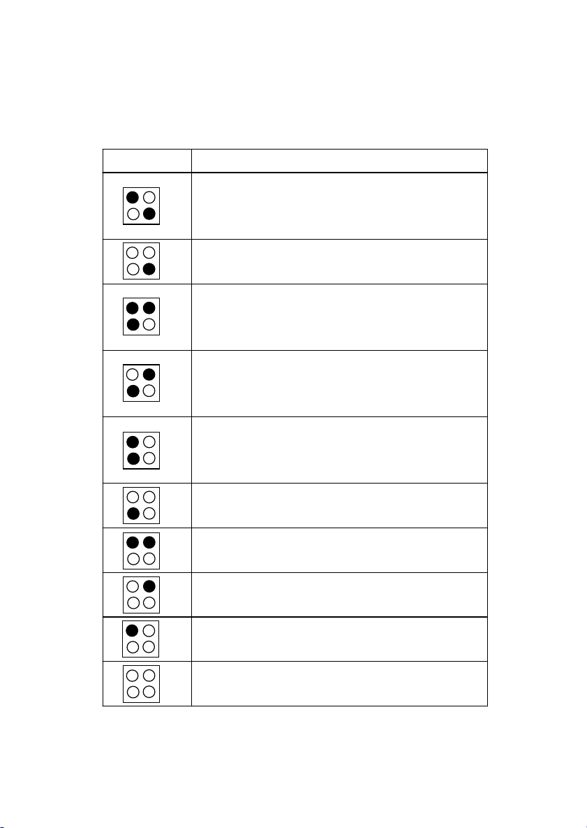
D-Bracket™ 2 Description
Processor Initialization
1 2
3 4
Initializing Video Interface
BIOS Sign On
Testing Base and Extended Memory
Initializing Hard Drive Controller
Initializing Floppy Drive Controller
Boot Attempt
Operating System Booting
- This will show information regarding the processor (like
brand name, system bus, etc…)
Testing RTC (Real Time Clock)
- This will start detecting CPU clock, checking type of video
onboard. Then, detect and initialize the video adapter.
- This will start showing information about logo, processor
brand name, etc….
- Testing base memory from 240K to 640K and extended
memory above 1MB using various patterns.
Assign Resources to all ISA.
- This will initialize IDE drive and controller.
- This will initializing Floppy Drive and controller.
- This will set low stack and boot via INT 19h.
Introduction
1-13
Page 47

Chapter 2.
Hardware Setup
Hardware Setup
This chapter provides you with the information about hardware setup
procedures. While doing the installation, be careful in holding the components
and follow the installation procedures. For some components, if you install in
the wrong orientation, the components will not work properly.
Use a grounded wrist strap before handling computer components. Static
electricity may damage the components.
This chapter contains the following topics:
Central Processing Unit: CPU 2 -2
Memory Installation 2-5
Power Supply 2-7
Back Panel 2- 9
Connectors 2-13
Jumpers 2-25
Slots 2-29
2
2-1
Page 48
Chapter 2
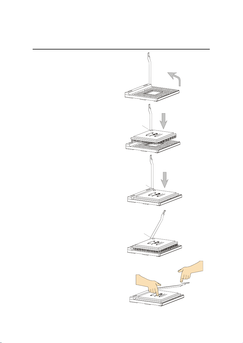
CPU Installation Procedures for Socket 478
1. Please turn off the power and
unplug the power cord before
installing the CPU.
2. Pull the lever sideways away
from the socket. Make sure
to raise the lever up to a 90degree angle.
3. Look for the cut edge. The cut
edge should point towards the
lever pivot. The CPU can only
fit in the correct orientation.
4. If the CPU is correctly
installed, the pins should be
completely embedded into the
socket and can not be seen.
Please note that any violation
of the correct installation
procedures may cause
permanent damages to your
mainboard.
5. Press the CPU down firmly into
the socket and close the lever.
As the CPU is likely to move
while the lever is being closed,
always close the lever with
your fingers pressing tightly
on top of the CPU to make sure
the CPU is properly and
completely embedded into the
socket.
Sliding
Plate
Dot / Cut edge
Dot / Cut edge
Dot / Cut edge
Open Lever
90 degree
Correct CPU placement
Press down
the CPU
O
X
Incorrect CPU placement
Close
Lever
2-2
Page 49
Hardware Setup
Installing the CPU Fan
As processor technology pushes to faster speeds and higher
performance, thermal managment becomes increasingly important. To dissipate heat, you need to attach the CPU cooling fan and heatsink on top of the
CPU. Follow the instructions below to install the Heatsink/Fan:
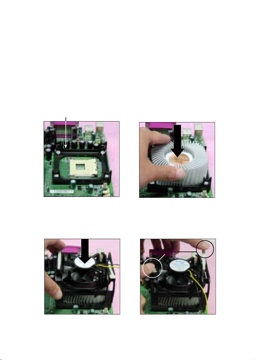
1. Locate the CPU and its retention
mechanism on the motherboard.
retention mechanism
3. Mount the fan on top of the heatsink.
Press down the fan until its four clips
get wedged in the holes of the retention mechanism.
2. Position the heatsink onto the reten-
tion mechanism.
4. Press the two levers down to fasten
the fan. Each lever can be pressed
down in only ONE direction.
levers
2-3
Page 50
Chapter 2
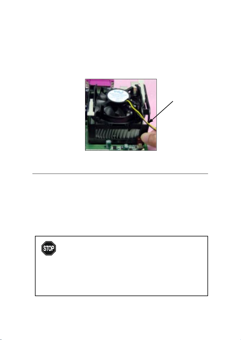
5. Connect the fan power cable from the mounted fan to the 3-pin fan power connector
on the board.
fan power cable
CPU Core Speed Derivation Procedure
If CPU Clock = 100MHz
Core/Bus ratio = 17
then CPU core speed = Host Clock x Core/Bus ratio
= 100MHz x 17
= 1.7GHz
Overclocking
This motherboard is designed to support overclocking.
WARNING!
However, please make sure your components are able to
tolerate such abnormal setting, while doing overclocking.
Any attempt to operate beyond product specifications is not
recommended. We do not guarantee the damages or risks
caused by inadequate operation or beyond product
specifications.
2-4
Page 51
Hardware Setup
Memory Installation
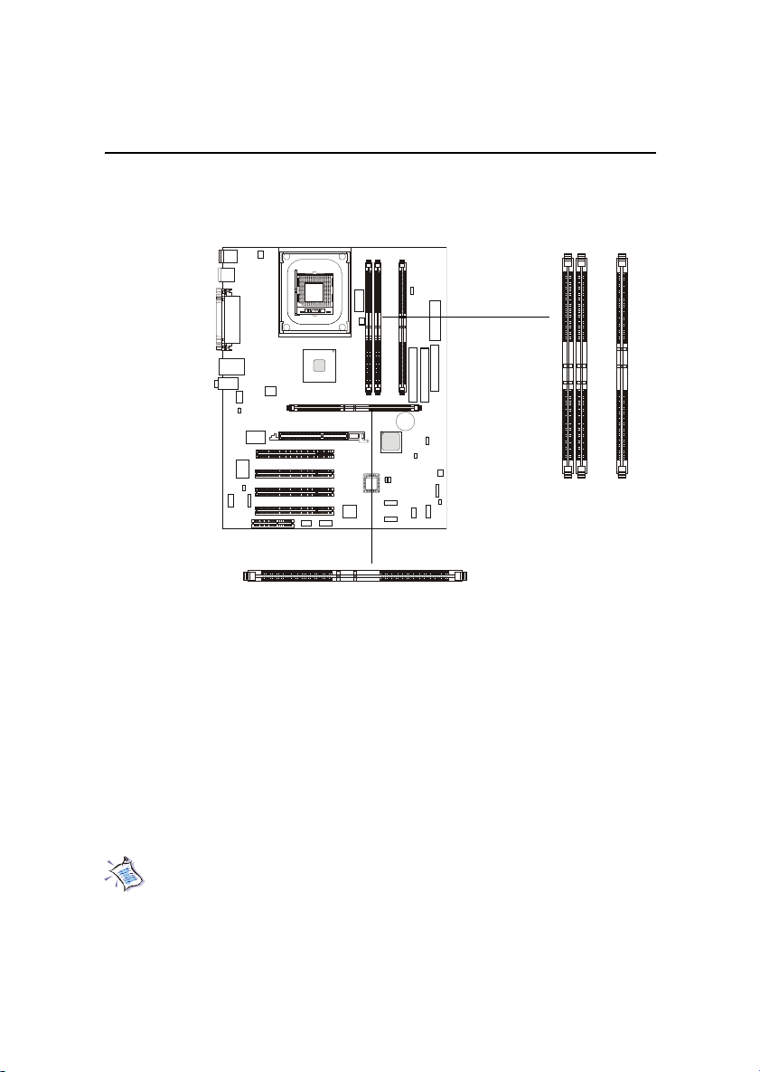
The mainboard provides 4 gold-lead sockets for 184-pin RIMM modules.
To operate properly, at least two RIMM modules must be installed. The
mainboard supports the memory size up to 2 GB.
RIMM Slots
(RIMM 1~4)
Memory Population Rules
z Support RIMM only.
z To operate properly, make sure that the RIMM banks are using the same
type and equal size density memory.
z Support PC600/PC800 RIMM.
z Support up to 16 Direct Rambus Device.
z Support ECC Single bit Correction and Multiple bit error detection
(Setting in BIOS).
z Install two RIMM modules either on “RIMM 1and RIMM 2” or on
“RIMM3 and RIMM4” slots.
About RIMM Module
RIMM module is a module integrated with RDRAM chips. It is similar to
a DIMM package but uses different pin settings. Rambus trademarked the term
RIMM as an entire word for a module using Rambus technology.
2-5
Page 52
Chapter 2
Installing RIMM Modules
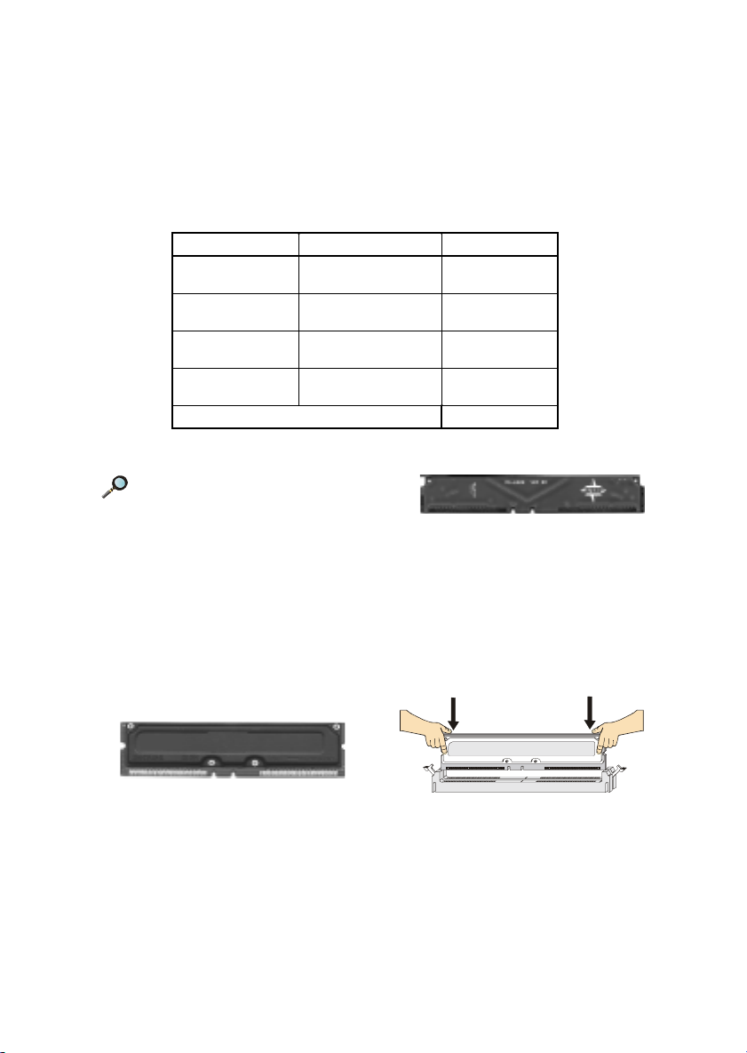
Y ou can install two or four RIMM modules in the following combination:
DIMM Socket Memory Module Total Memory
Socket 1
(Bank 0 & Bank 1)
Socket 2
(Bank 2 & Bank 3)
Socket 3
(Bank 4 & Bank 5)
Socket 4
(Bank 6 & Bank 7)
Total System Memory 64MB ~ 2GB
Note: If only two RIMM slots are
populated, you must install C-RIMM
(Continuity RIMM) modules on the other
unused RIMM slots. A C-RIMM module is a dummy module for continuing
the signal connection.
32MB, 64MB, 128MB,
256MB, 512MB
32MB, 64MB, 128MB,
256MB, 512MB
32MB, 64MB, 128MB,
256MB, 512MB
32MB, 64MB, 128MB,
256MB, 512MB
32MB ~ 512MB
32MB ~ 512MB
32MB ~ 512MB
32MB ~ 512MB
C-RIMM Module
1. The RIMM slot has 2 Notch
Keys, so the RIMM memory
module can only fit in one
orientation.
RIMM Module
3. The plastic clips at sides of the
RIMM slot will automatically
close.
2. Insert the RIMM memory module
vertically into the RIMM slot.
Then push it in.
4. If you won’t insert any RIMM
modules on the other two RIMM
slots, you must install C-RIMM
modules on the empty slots.
2-6
Page 53
Hardware Setup
Power Supply
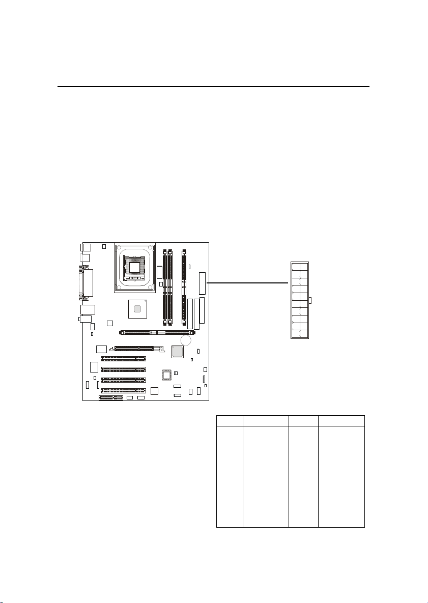
The mainboard supports ATX power supply for the power system. Before inserting the power supply connector, always make sure that all components are installed properly to ensure that no damage will be caused.
ATX 20-Pin Power Connector: JPWR1
This connector allows you to connect to an ATX power supply. To
connect to the ATX power supply , make sure the plugs of the power supply is
inserted in the proper orientation and the pins are aligned. Then push down
the power supply firmly into the connector. The power connector supports
instant power on function which means that system will boot up immediately
when the power supply connector is inserted on the board.
10
20
1
11
JPWR1
JPWR1 Pin Definition
PIN SIGNAL
1 3.3V
2 3.3V
3 GND
45V
5 GND
65V
7 GND
8 PW_OK
9 5V_SB
10 12V
2-7
PIN SIGNAL
11 3.3V
12 -12V
13 GND
14 PS_ON
15 GND
16 GND
17 GND
18 -5V
19 5 V
20 5 V
Page 54
Chapter 2
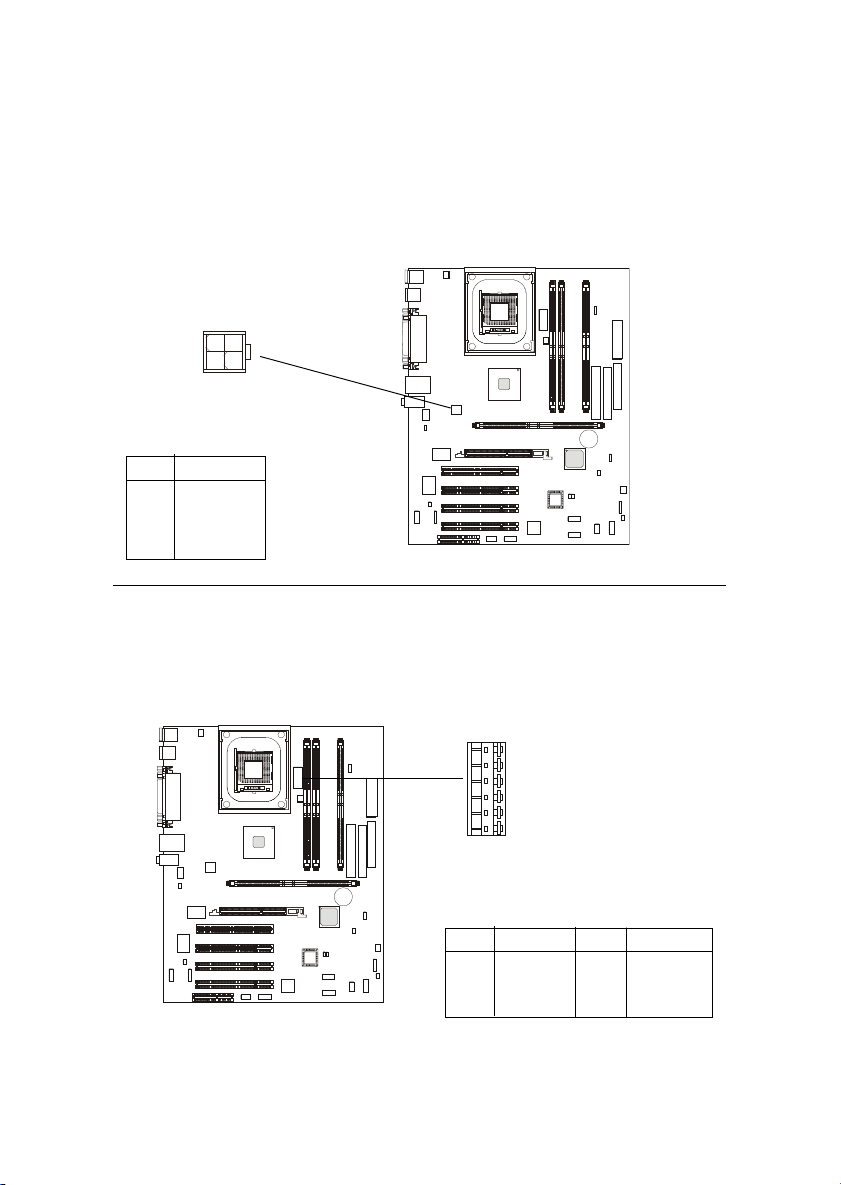
ATX 12V Power Connector: JPWR3
Attaching the ATX power supply to the connector help offer sufficient
voltage to Pentium 4 CPU. This power connector also supports instant power
on function.
1
234
JPWR3
PIN SIGNAL
1 GND
2 GND
3 12V
4 12V
ATX 5V/3V Power Connector: JPWR2
The mainboard provides an extra 5V/3V power connector for you to
connect to the ATX power supply.
JPWR2
PIN SIGNAL
1 GND
2 GND
3 GND
2-8
6
1
PIN SIGNAL
4 3.3V
5 3.3V
65V
Page 55
Back Panel
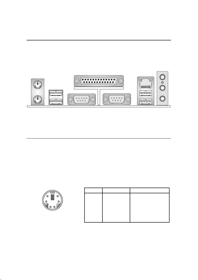
The Back Panel provides the following connectors:
Hardware Setup
Mouse
Parallel
LAN
(Optional)
MIC
USB Ports
Keyboard
COM A COM B
USB Ports
L-in
L-out
Mouse Connector: JKBMS1
The mainboard provides a standard PS/2® mouse mini DIN connector for
attaching a PS/2® mouse. You can plug a PS/2® mouse directly into this
connector. The connector location and pin assignments are as follows:
Pin Definition
6
4
2
PS/2 Mouse (6-pin Female)
5
3
1
PIN SIGNAL DESCRIPTION
1 Mouse DATA Mouse DATA
2 NC No connection
3 GND Ground
4 VCC +5V
5 Mouse Clock Mouse clock
6 NC No connection
2-9
Page 56
Chapter 2
Keyboard Connector: JKBMS1
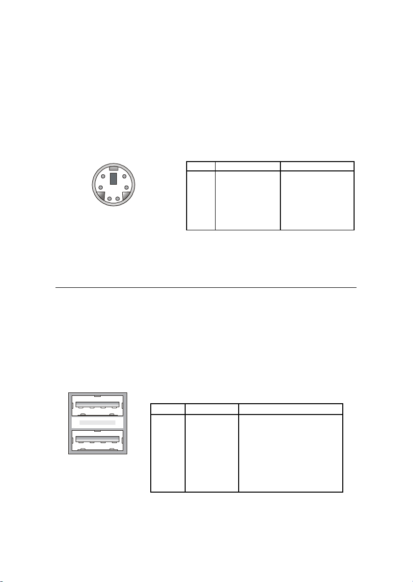
The mainboard provides a standard PS/2® keyboard mini DIN connector
for attaching a PS/2® keyboard. You can plug a PS/2® keyboard directly into
this connector.
Pin Definition
6
4
2
5
3
1
PS/2 Keyboard (6-pin Female)
PIN SIGNAL DESCRIPTION
1 Keyboard DAT A Keyboard DATA
2 NC No connection
3 GND Ground
4 VCC +5V
5 Keyboard Clock Keyboard clock
6 NC No connection
USB 1.1 Connectors
The mainboard provides a UHCI (Universal Host Controller Interface)
Universal Serial Bus root for attaching USB devices such as keyboard, mouse
or other USB-compatible devices. You can plug the USB device directly into
ths connector.
1 2 3 4
5 6 7 8
USB Ports
USB Port Description
PIN SIGNAL DESCRIPTION
1 VCC +5V
2 -Data 0 Negative Data Channel 0
3 +Data0 Positive Data Channel 0
4 GND Ground
5 VCC +5V
6 -Data 1 Negative Data Channel 1
7 +Data 1 Positive Data Channel 1
8 GND Ground
2-10
Page 57
Hardware Setup
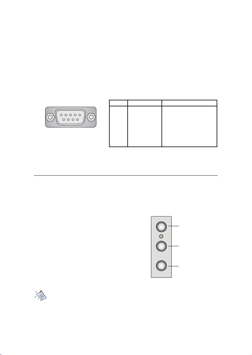
Serial Port Connector: COM A & COM B
The mainboard offers two 9-pin male DIN connectors for serial port COM
A and COM B. The ports are 16550A high speed communication ports that
send/receive 16 bytes FIFOs. You can attach a serial mouse or other serial
devices directly to them.
Pin Definition
1 2 3 4 5
6 7 8 9
9-Pin Male DIN Connectors
PIN SIGNAL DESCRIPTION
1 DCD Data Carry Detect
2 SIN Serial In or Receive Data
3 SOUT Serial Out or Transmit Data
4 DTR Data T erminal Ready)
5 GND Ground
6 DSR Data Set Ready
7 RTS Request T o Send
8 CTS Clear To Send
9 RI Ring Indicate
Audio Port Connectors
Line Out is a connector for Speakers or Headphones. Line In is used for
external CD player, Tape player, or other audio devices. Mic is a connector for
microphones.
MIC
Line In
1/8” Stereo Audio Connectors
Line Out
Note: Details on the application of 6-channel audio can be acquired
by installing the CMI8738 Audio Driver on the CD-ROM (enclosed in
the product package).
2-11
Page 58
Chapter 2
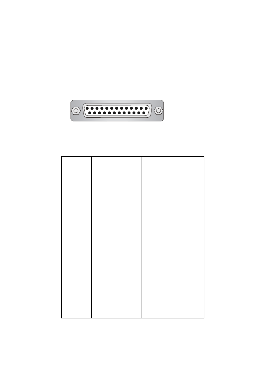
Parallel Port Connector: LPT1
The mainboard provides a 25-pin female centronic connector for LPT. A
parallel port is a standard printer port that supports Enhanced Parallel Port
(EPP) and Extended Capabilities Parallel Port (ECP) mode.
13 1
25
14
Pin Definition
PIN SIGNAL DESCRIPTION
1 STROBE Strobe
2 DATA0 Data0
3 DATA1 Data1
4 DATA2 Data2
5 DATA3 Data3
6 DATA4 Data4
7 DATA5 Data5
8 DATA6 Data6
9 DATA7 Data7
10 ACK# Acknowledge
11 BUSY Busy
12 PE Paper End
13 SELECT Select
14 AUTO FEED# Automatic Feed
15 ERR# Error
16 INIT# Initialize Printer
17 SLIN# Select In
18 GND Ground
19 GND Ground
20 GND Ground
21 GND Ground
22 GND Ground
23 GND Ground
24 GND Ground
25 GND Ground
2-12
Page 59
Hardware Setup
Connectors
The mainboard provides connectors to connect to FDD, IDE HDD, case,
modem, LAN, USB Ports, IR module and CPU/System F AN.
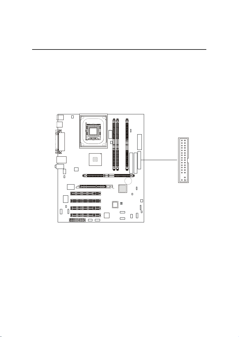
Floppy Disk Drive Connector: FDD1
The mainboard provides a standard floppy disk drive connector that
supports 360K, 720K, 1.2M, 1.44M and 2.88M floppy disk types.
FDD1
2-13
Page 60
Chapter 2
Hard Disk Connectors: IDE1 & IDE2
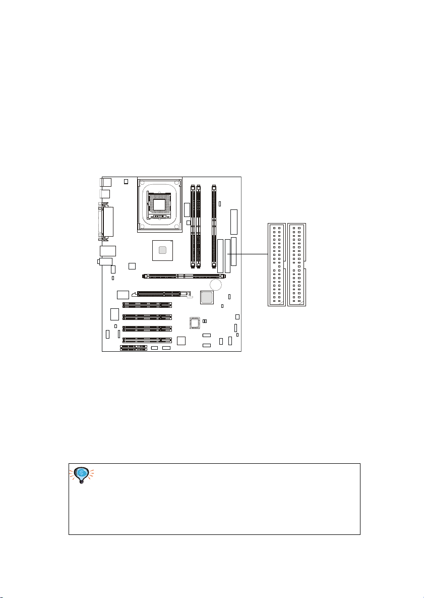
The mainboard has a 32-bit Enhanced PCI IDE and Ultra DMA 33/66/100
controller that provides PIO mode 0~4, Bus Master, and Ultra DMA/33/66/100
function. Y ou can connect up to four hard disk drives, CD-ROM, 120MB Floppy
(reserved for future BIOS) and other devices. These connectors support the
provided IDE hard disk cable.
IDE2 IDE1
IDE1 (Primary IDE Connector)
The first hard drive should always be connected to IDE1. IDE1 can
connect a Master and a Slave drive. You must configure second hard
drive to Slave mode by setting the jumper accordingly.
IDE2 (Secondary IDE Connector)
IDE2 can also connect a Master and a Slave drive.
TIP:
If you install two hard disks on cable, you must configure the
second drive to Slave mode by setting its jumper. Refer to the
hard disk documentation supplied by hard disk vendors for jumper
setting instructions.
2-14
Page 61
Hardware Setup
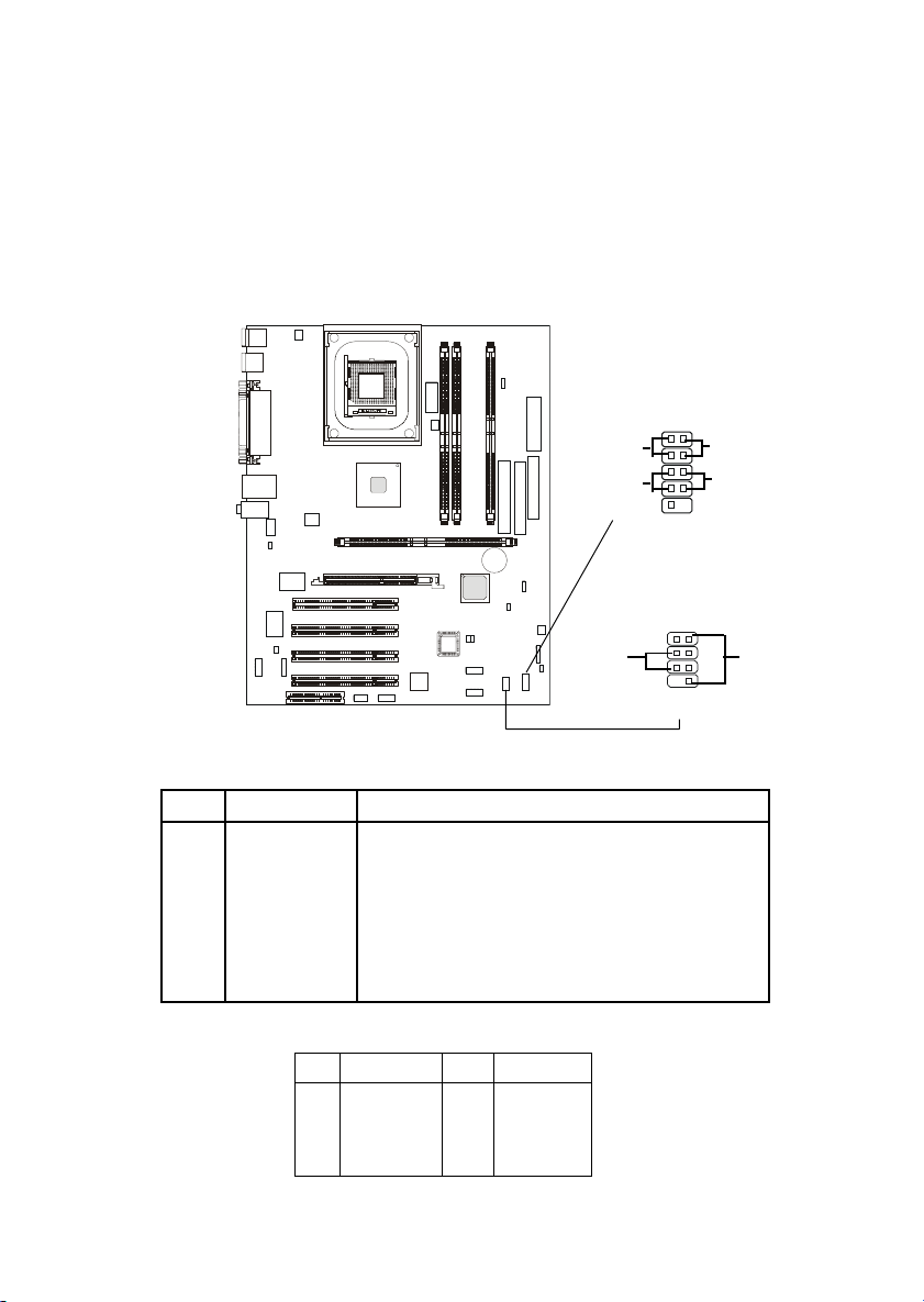
Front Panel Connector: JFP1 and JFP2 (Optional Intel
spec)
This connector is for electrical connection to the front panel switches
and LEDs.
JFP1
(Intel spec)
1
2
109
JFP2
12
Power
LED
Power
Switch
Speaker
87
HDD
LED
Reset
Switch
Power
LED
JFP1 Pin Definition
PIN SIGNAL DESCRIPTION
1 HD_LED_P Hard disk LED pull-up
2 FP PWR/SLP MSG LED pull-up
3 HD_LED_N Hard disk active LED
4 FP PWR/SLP MSG LED pull-up
5 RST_SW_1 Reset Switch 1
6 PWR_SW_P Power Switch high reference pull-up
7 RST_SW_2 Reset Switch 2
8 PWR_SW_N Power Switch low reference pull-down to GND
9 RSVD_DNU Reserved. Do not use.
JFP2 Pin Definition
PIN SIGNAL PIN SIGNAL
1 GND 2 SPK3 SLED 4 BUZ+
5 PLED 6 BUZ7 NC 8 SPK+
2-15
Page 62
Chapter 2
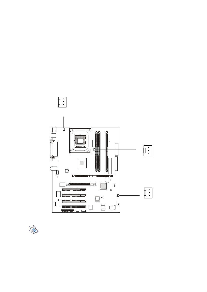
Fan Power Connectors: CPUFAN/SYSFAN/PSFAN
The CPUF AN (processor fan), SYSF AN (system fan) and PSFAN (power
supply fan) support system cooling fan with +12V. It supports three-pin head
connector. When connecting the wire to the connectors, always take note that
the red wire is the positive and should be connected to the +12V, the black wire
is Ground and should be connected to GND. If the mainboard has a System
Hardware Monitor chipset on-board, you must use a specially designed fan
with speed sensor to take advantage of the CPU fan control.
GND
+12V
SENSOR
CPUFAN
GND
+12V
SENSOR
PSFAN
GND
+12V
SENSOR
SYSFAN
Note:
1. Always consult the vendor for proper CPU cooling fan.
2. CPU Fan supports the fan control. You can install the PC Alert
utility that will automatically control the CPU Fan speed according to the actual CPU temeperature.
2-16
Page 63
Hardware Setup
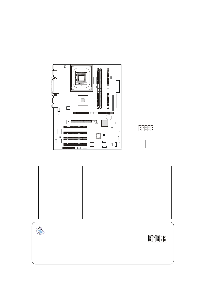
Front Panel Audio Connector: JAUD1 (Optional Intel spec)
This connector allows you to connect to the front panel audio.
JAUD1
1
9
2
10
Pin Definition
PIN SIGNAL DESCRIPTION
1 AUD_MIC Front panel microphone input signal
2 AUD_GND Ground used by analog audio circuits
3 AUD_MIC_BIAS Microphone power
4 AUD_VCC Filtered +5V used by analog audio circuits
5 AUD_FPOUT_R Right channel audio signal to front panel
6 AUD_RET_R Right channel audio signal return from front panel
7 HP_ON Reserved for future use to control headphone amplifier
8 KEY No pin
9 AUD_FPOUT_L Left channel audio signal to front panel
10 AUD_RET_L Left channel audio signal return from front panel
Note:
If you don’t want to connect to the front audio
9
header, pins 5 & 6, 9 & 10 have to be jumpered
in order to have signal output directed to the
rear audio ports. Otherwise, the Line-Out connector on the back panel will not function.
2-17
5
610
Page 64
Chapter 2
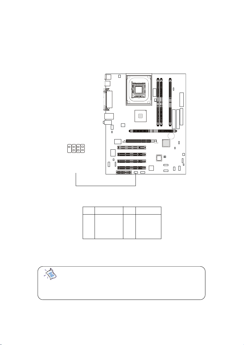
Bluetooth Connector: JBT1 (Optional)
This connector is used to connect a bluetooth module for wireless
connection.
1
7
2
8
JBT1
Pin Definition
PIN SIGNAL PIN SIGNAL
1 5VDUAL 2 3VDUAL
3 D+ (USB signal) 4 GND
5 D- (USB signal) 6 GND
7 GND 8 NC
Note: Because the bluetooth connector shares the USB1.1
connector, the upper USB1 USB 1.1 port will not function
when you attach a bluetooth module to this connector.
2-18
Page 65
Hardware Setup
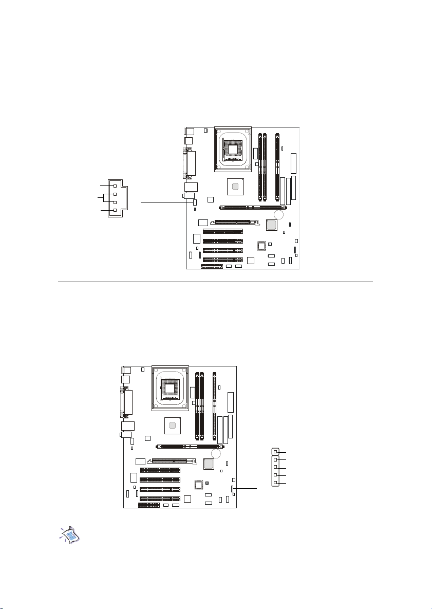
CD-In Connector: JCD1
JCD1 connector is for CD-ROM audio connector.
R
GND
L
JCD1
Wake On Ring Connector: JWR1
This connector allows you to connect to a modem card with Wake On
Ring function. The connector will power up the system when a signal is received through the modem card.
1
JWR1
Note: Modem wake-up signal is active “low”.
2-19
NC
GND
MDM_WAKEUP
NC
5VSB
Page 66
Chapter 2
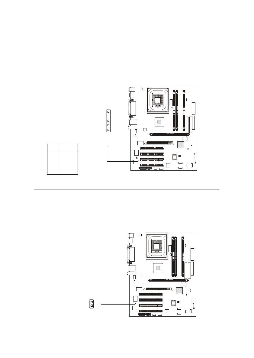
IrDA Infrared Module Connector: JIR1
This connector allows you to connect to an IrDA Infrared module. You
must configure the setting through the BIOS setup to use the IR function.
1
JIR1
Pin Signal
1 VCC
2NC
3 IRRX
4 GND
5 IRTX
Chassis Intrusion Switch Connector: JCI1
The connector is connected to a 2-pin chassis switch. If the chassis is
opened, the switch will be short. The system will record this status and show
a warning message on the screen. To clear the warning, you must enter the
BIOS utility and clear the record.
JCI1
2-20
Page 67
Hardware Setup
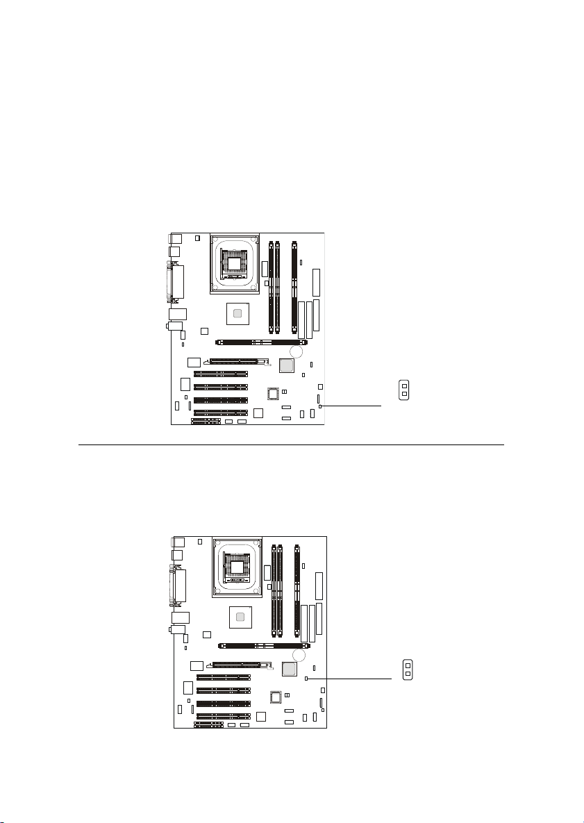
Remote Power On/Off Switch Connector: JRMS1
Connect to a 2-pin push button switch. When OFF, pressing the button can turn the system on. When ON, pressing the button once will make the
system enter the sleep/suspend state. If the button is pressed for more than
four seconds, the system will be turned off. To change the setup, go to the
BIOS Power Management Setup.
JRMS1
Power Saving Switch Connector: JGS1
Attach a power saving switch to this connector. Pressing the switch
once will have the system enter the sleep/suspend state. Press any key to wake
up the system.
2-21
JGS1
Page 68
Chapter 2
Front USB 2.0 Connectors: JUSB1 & JUSB2 (Optional)
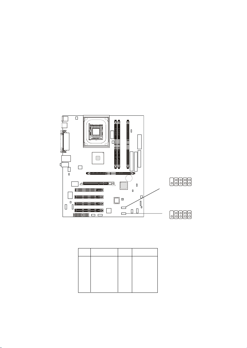
The mainboard provides two USB 2.0 pin headers USB1 & USB2 (optional
USB 2.0 Bracket available). USB 2.0 technology increases data transfer rate up
to a maximum throughput of 480Mbps, which is 40 times faster than USB 1.1,
and is ideal for connecting high-speed USB interface peripherals such as USB
HDD, digital cameras, MP3 players, printers, modems and the like. Both
USB1 & USB3 are compliant with Intel® Front Panel I/O Connectivity Design
Guide.
Pin Definition
PIN SIGNAL PIN SIGNAL
1 USBPWR 2 USBPWR
3 USBP2- 4 USBP35 USBP2+ 6 USBP3+
7 GND 8 GND
9 NC 10 USBOC
2-22
9
10
9
10
JUSB2
JUSB1
1
2
1
2
Page 69
Hardware Setup
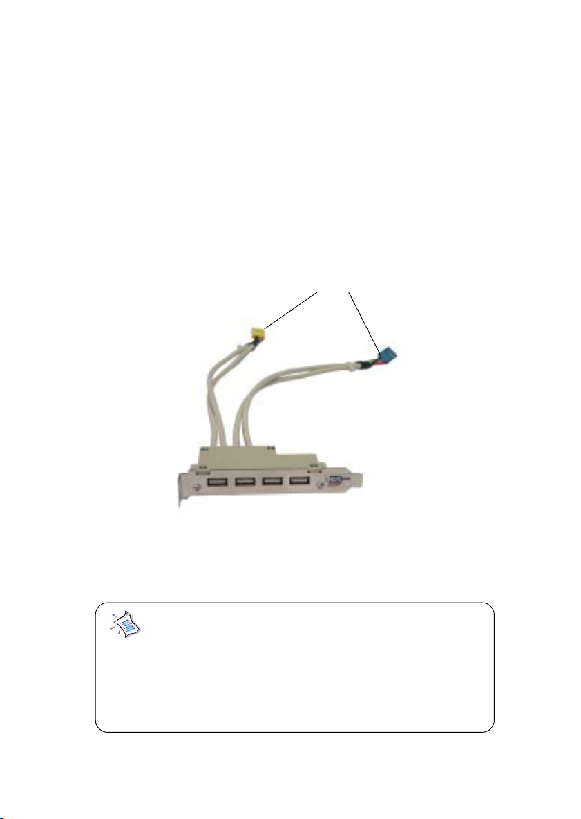
T o Attach the Optional USB 2.0 Ports:
1. Take out the USB 2.0 bracket
2. Locate the JUSB1 and JUSB2 pin headers on the motherboard.
3. Connect the USB cables from USB 2.0 bracket to the JUSB1 and JUSB2 pin
headers separately. The blue connector of the USB bracket should be attached to the blue pin header on the board, and the yellow connector to the
yellow pin header on the board.
Connected to JUSB1 & JUSB2 separately
USB 2.0 Bracket
4. Place the USB 2.0 bracket into the appropriate slot of the system case.
Note: The USB 2.0 controller is backwards compatible
with USB 1.1 spec. To use the USB 2.0 ports, you still
need to install USB 2.0 driver, which is supplied by
Microsoft for Windows® 2000 and XP. If you have any
problems regarding USB 2.0 driver, please visit Microsoft
website for more information.
2-23
Page 70
Chapter 2
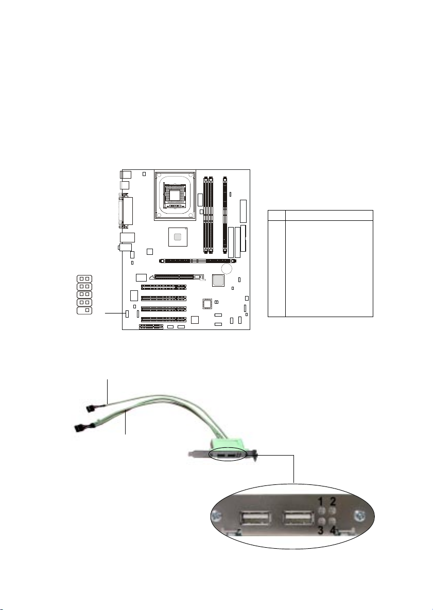
D-Bracket™ 2 Connector: JDB1
The D-Bracket™ 2 is a USB Bracket that supports both USB 1.1 & 2.0
spec. It integrates four LEDs and allows users to identify system problems
through 16 various combinations of LED signals. For definitions of 16 signal
combinations, please refer to D-Bracket™ 2 in Chapter 1.
JDB1 Pin Definition
Pin Signal
1 DBG1 (high for green color)
2 DBR1 (high for red color)
3 DBG2 (high for green color)
4 DBR2 (high for red color)
5 DBG3 (high for green color)
1
9
2
10
JDB1
6 DBR3 (high for red color)
7 DBG4 (high for green color)
8 DBR4 (high for red color)
9 Key
10 NC
Connected to JDB1
Connected to USB1
D-Bracket™ 2
2-24
Page 71
Hardware Setup
Jumpers
The motherboard provides one jumper for you to set the computer’s
function. This section will explain how to change your motherboard’s function
through the use of the jumper.
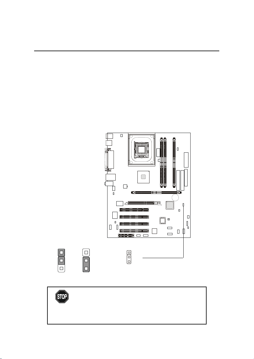
Clear CMOS Jumper: JBAT1
There is a CMOS RAM on board that has a power supply from external
battery to keep the data of system configuration. With the CMOS RAM, the
system can automatically boot OS every time it is turned on. That battery has
long life time for at least 5 years. If you want to clear the system configuration,
use the JBAT1 (Clear CMOS Jumper ) to clear data. Follow the instructions
below to clear the data:
1
3
Keep Data
WARNING!
1
3
Clear Data
1
JBAT1
You can clear CMOS by shorting 2-3 pin while the
system is off. Then return to 1-2 pin position. Avoid
clearing the CMOS while the system is on; it will
damage the mainboard.
2-25
Page 72
Chapter 2
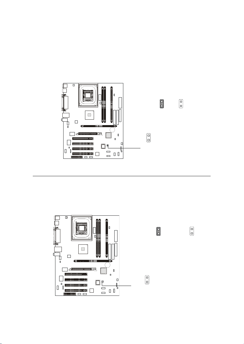
Clear BIOS Password Jumper: J6
The jumper is used to clear the BIOS password. T o clear the password,
open the jumper and restart your computer.
Normal
J6
Clear
BIOS Flash Jumper: J5
This jumper is used to lock or unlock the boot block area on BIOS.
When unlocked, the BIOS boot block area can be updated. When locked, the
BIOS boot block area cannot be updated.
BIOS Flash
Locked
BIOS Flash
Unlocked
2-26
J5
Page 73
Hardware Setup
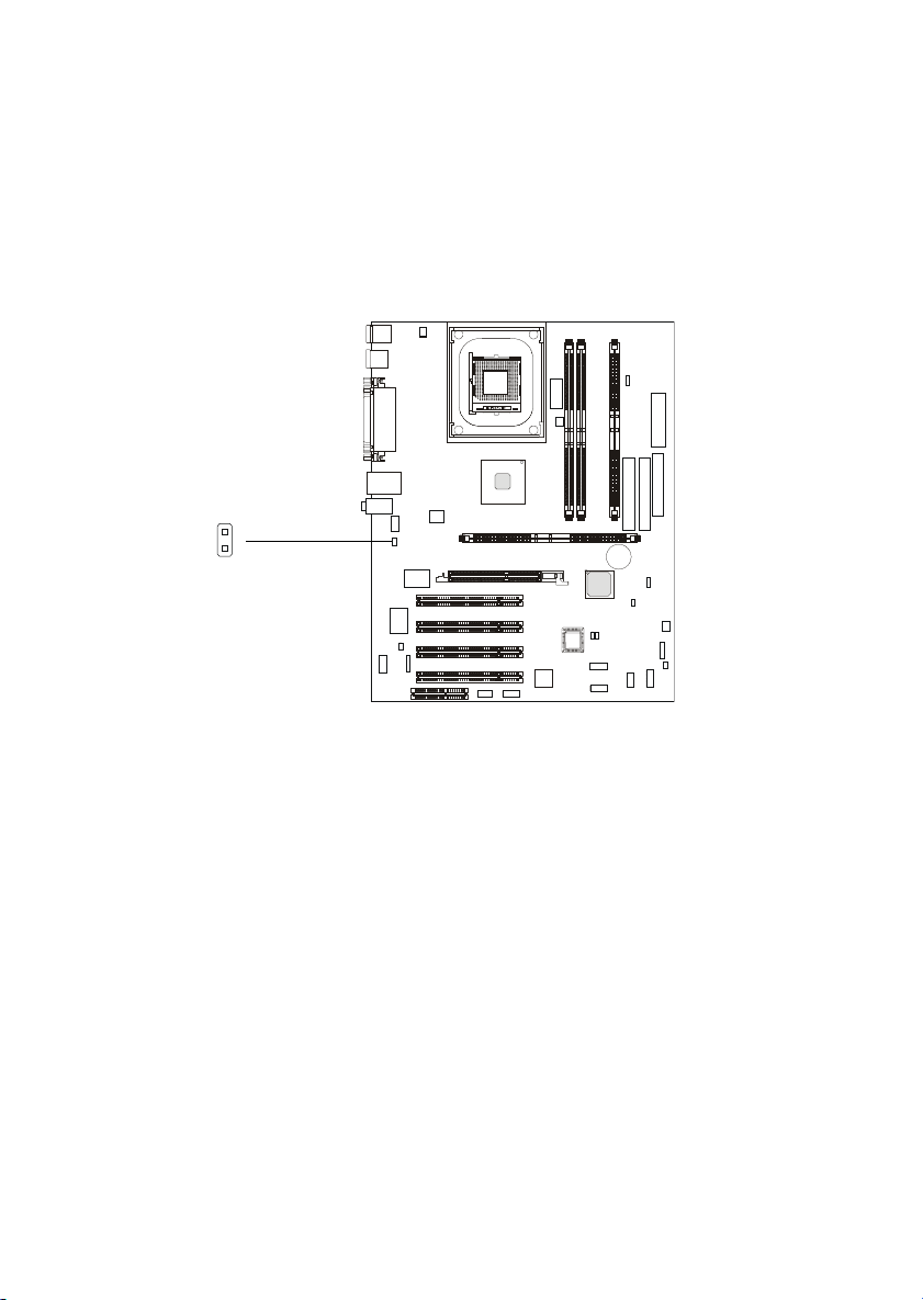
LAN Enable/Disable Jumper: J2
The jumper is used to disable the onboard LAN function, and the status
should be set in the BIOS Setup program.
J2
2-27
Page 74
Chapter 2
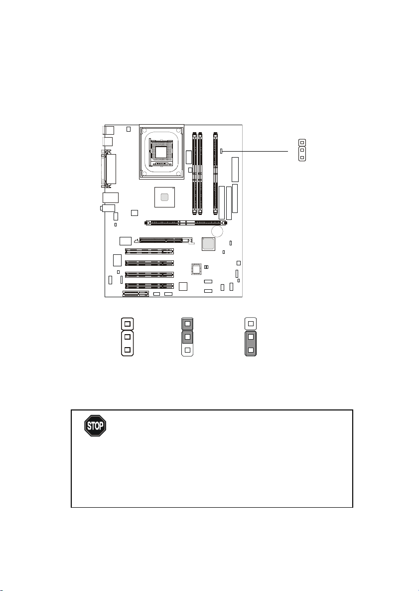
RDRAM Over Voltage Jumper: J1
The jumper is used to set the RDRAM voltage for overcolcking purpose.
1
J1
WARNING!
1
Normal
(2.6V)
1
3
Over Voltage
(2.58V)
1
3
Over Voltage
(2.68V)
This motherboard is designed to support over voltage.
However, please make sure your components are able
to tolerate such abnormal setting while doing over
voltage. Any attempt to operate beyond product
specification is not recommended. We do not guarantee
the damages or risks caused by inadequate operation
or beyond product specifications.
.
2-28
Page 75
Hardware Setup
Slots
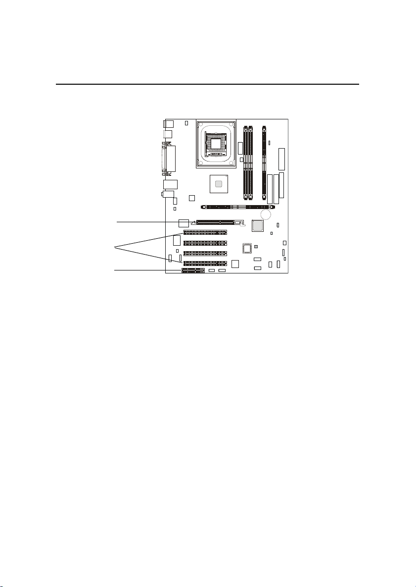
The motherboard provides four 32-bit Master PCI Bus Slots, one AGP
and one CNR slot.
AGP Slot
PCI Slots
CNR Slot
AGP (Accelerated Graphics Port) Slot
The AGP slot allows you to insert the AGP graphics card only. AGP is an
interface specification designed for the throughput demands of 3D graphics.
It introduces a 66MHz, 32-bit channel for the graphics controller to directly
access main memory. The slot only supports 1.5V 4x AGP card.
PCI Slots
Four PCI slots allow you to insert the expansion cards to meet your
needs. When adding or removing expansion cards, make sure that you unplug
the power supply first. Meanwhile, read the documentation for the expansion
card to make any necessary hardware or software settings for the expansion
card, such as jumpers, switches or BIOS configuration.
CNR (Communication Network Riser) Slot
The CNR slot allows you to insert the CNR expansion cards. CNR is a
specially designed network, audio, or modem riser card for ATX family
motherboards. Its main processing is done through software and controlled by
the motherboard’s chipset.
2-29
Page 76

Chapter 2
PCI Interrupt Request Routing
The IRQ, abbreviation of interrupt request line and pronounced I-R-Q,
are hardware lines over which devices can send interrupt signals to the
microprocessor. The PCI IRQ pins are typically connected to the PCI bus as
follows:
Order 1 Order 2 Order 3 Order 4
PCI Slot 1 INT C# INT F# INT G# INT A#
PCI Slot 2 INT F# INT G# INT A# INT C#
PCI Slot 3 INT G# INT A# INT C# INT F#
PCI Slot 4 INT A# INT C# INT F# INT G#
2-30
Page 77

AWARD® BIOS Setup
Chapter 3. AWARD® BIOS Setup
AWARD® BIOS Setup
The mainboard uses AWARD® BIOS Setup program that provides a
Setup utility for users to modify the basic system configuration. The information is stored in a battery-backed CMOS RAM so it retains the Setup information when the power is turned off.
This chapter provides you with the overview of the BIOS Setup program.
It contains the following topics:
Entering Setup 3-2
Control Keys 3-2
Getting Help 3-3
The Main Menu 3-4
Standard CMOS Features 3-6
Advanced BIOS Features 3-8
Advanced Chipset Features 3-12
Integrated Peripherals 3-14
Power Management Setup 3-19
PNP/PCI Configurations 3-23
PC Health Status 3-25
Frequency/Voltage Control 3-26
High System Performance 3-28
Load Optimized Defaults 3-29
Set Supervisor/User Password 3-30
Save & Exit Setup 3-32
Exit Without Saving 3-33
3
3-1
Page 78

Chapter 3
Entering Setup
Power on the computer and the system will start POST (Power On Self Test)
process. When the message below appears on the screen, press <DEL> key to
enter Setup.
Press DEL to enter SETUP
If the message disappears before you respond and you still wish to enter
Setup, restart the system by turning it OFF and On or pressing the RESET
button. You may also restart the system by simultaneously pressing <Ctrl>,
<Alt>, and <Delete> keys.
Control Keys
<↑>
<↓>
<←>
<→>
<Enter> Select the item
<Esc> Jumps to the Exit menu or returns to the main menu from a submenu
<+/PU> Increase the numeric value or make changes
<-/PD> Decrease the numeric value or make changes
<F1> General help, only for Status Page Setup Menu and Option Page
<F5> Restore the previous CMOS value from CMOS, only for Option Page
<F6> Load the default CMOS value from Fail-Safe default table, only for
<F7> Load Optimized defaults
<F10> Save all the CMOS changes and exit
Move to the previous item
Move to the next item
Move to the item in the left hand
Move to the item in the right hand
Setup Menu
Setup Menu
Option Page Setup Menu
3-2
Page 79

AWARD® BIOS Setup
Getting Help
After entering the Setup menu, the first menu you will see is the Main Menu.
Main Menu
The main menu lists the setup functions you can make changes to. You can use
the control keys ( ↑↓ ) to select the item. The on-line description of the high-
lighted setup function is displayed at the bottom of the screen.
Sub-Menu
If you find a right pointer symbol (as shown
in the right view) appears to the left of certain
fields that means a sub-menu containing additional options can be launched from this
field. You can use control keys ( ↑↓ ) to high-
light the field and press <Enter> to call up the
sub-menu. Then you can use the control keys
to enter values and move from field to field
within a sub-menu. If you want to return to
the main menu, just press <Esc >.
General Help <F1>
The BIOS setup program provides a General Help screen. You can call up this
screen from any menu by simply pressing <F1>. The Help screen lists the
appropriate keys to use and the possible selections for the highlighted item.
Press <Esc> to exit the Help screen.
3-3
Page 80
Chapter 3
The Main Menu
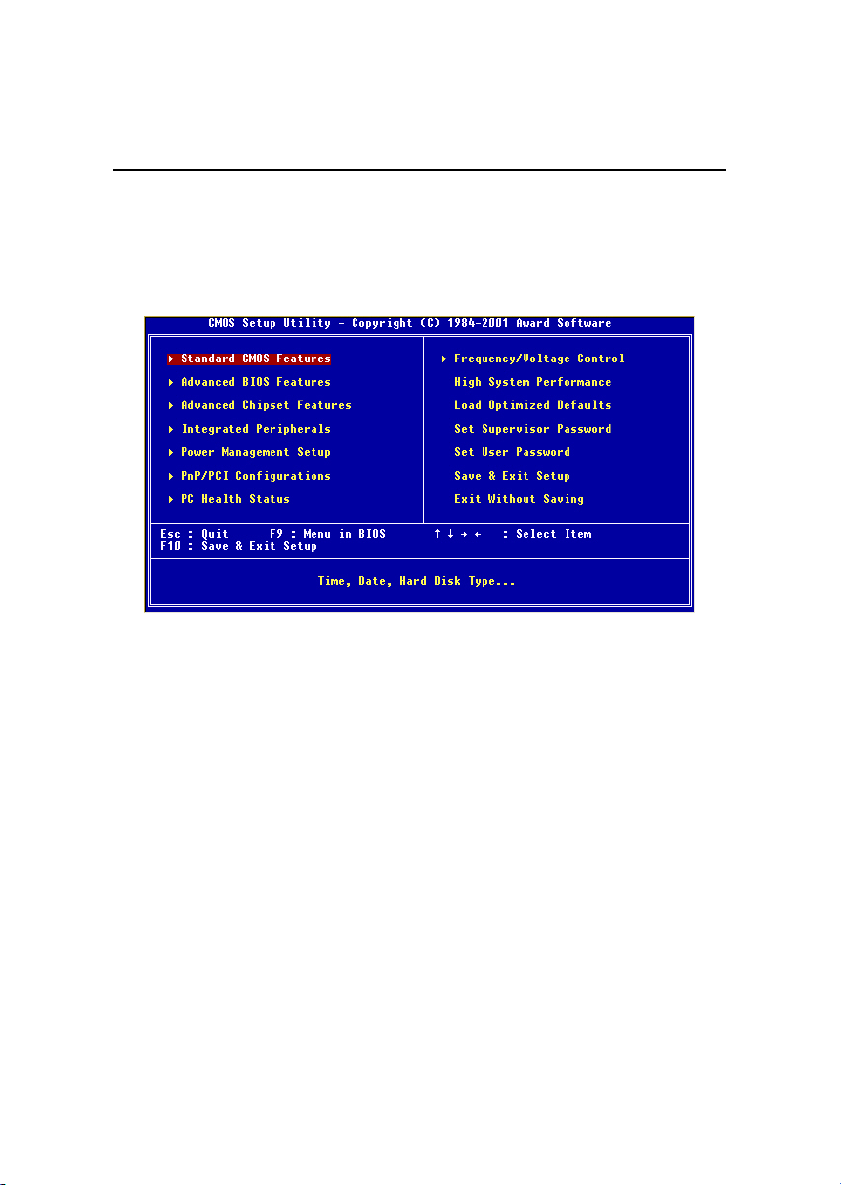
Once you enter Award® BIOS CMOS Setup Utility, the Main Menu (Figure 1)
will appear on the screen. The Main Menu allows you to select from twelve
setup functions and two exit choices. Use arrow keys to select among the items
and press <Enter> to accept or enter the sub-menu.
Standard CMOS Features
Use this Menu for basic system configurations.
Advanced BIOS Features
Use this menu to set the Advanced Features available on your system.
Advanced Chipset Features
Use this menu to change the values in the chipset registers and optimize your
system’s performance.
Integrated Peripherals
Use this menu to specify your settings for integrated peripherals.
Power Management Setup
Use this menu to specify your settings for power management.
PnP/PCI Configurations
This entry appears if your system supports PnP/PCI.
3-4
Page 81

AWARD® BIOS Setup
PC Health Status
This entry shows your PC health status.
Frequency/Voltage Control
Use this menu to specify your settings for frequency/voltage control.
High System Performance
Use this menu to load the BIOS values for the best system performance, but
the system stability may be affected.
Load Optimized Defaults
Use this menu to load factory default settings into the BIOS for optimal and
stable system operations.
Set Supervisor/User Password
Use this menu to set User and Supervisor Passwords.
Save & Exit Setup
Save CMOS value changes to CMOS and exit setup.
Exit Without Saving
Abandon all CMOS value changes and exit setup.
3-5
Page 82
Chapter 3
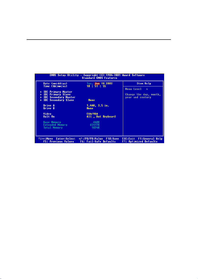
Standard CMOS Features
The items in Standard CMOS Features Menu are divided into 10 categories.
Each category includes no, one or more than one setup items. Use the arrow
keys to highlight the item and then use the <PgUp> or <PgDn> keys to select
the value you want in each item.
Date
The date format is <day><month> <date> <year>.
day Day of the week, from Sun to Sat, determined by BIOS. Read-only.
month The month from Jan. through Dec.
date The date from 1 to 31 can be keyed by numeric function keys.
year The year, depends on the year of the BIOS
Time
The time format is <hour> <minute> <second>.
IDE Primary/Secondary Master/Slave
Press PgUp/<+> or PgDn/<-> to select Manual, None, Auto type. Note that the
specifications of your drive must match with the drive table. The hard disk will
not work properly if you enter improper information for this category. If your
hard disk drive type is not matched or listed, you can use Manual to define
your own drive type manually.
If you select Manual, related information is asked to be entered to the follow-
3-6
Page 83

AWARD® BIOS Setup
ing items. Enter the information directly from the keyboard. This information
should be provided in the documentation from your hard disk vendor or the
system manufacturer.
If the controller of HDD interface is SCSI, the selection shall be “None”.
If the controller of HDD interface is CD-ROM, the selection shall be “None”.
Access Mode The settings are CHS, LBA, Large, Auto.
Capacity The formatted size of the storage device.
Cylinder Number of cylinders.
Head Number of heads.
Precomp Write precompensation.
Landing Zone Cylinder location of the landing zone.
Sector Number of sectors.
Drive A/B
This item allows you to set the type of floppy drives installed. Available
options are None, 360K, 5.25 in., 1.2M, 5.25 in., 720K, 3.5 in., 1.44M, 3.5 in.,
2.88M, 3.5 in.
Video
The setting controls the type of video adapter used for the primary monitor of
the system. Available options are EGA/VGA , CGA 40, CGA 80 and Mono.
Halt On
The setting determines whether the system will stop if an error is detected at
boot. Available options are:
All Errors The system stops when any error is detected.
No Errors The system doesn’t stop for any detected error.
All, But Keyboard The system doesn’t stop for a keyboard error.
All, But Diskette The system doesn’t stop for a disk error.
All, But Disk/Key The system doesn’t stop for either a disk or a
keyboard error.
3-7
Page 84
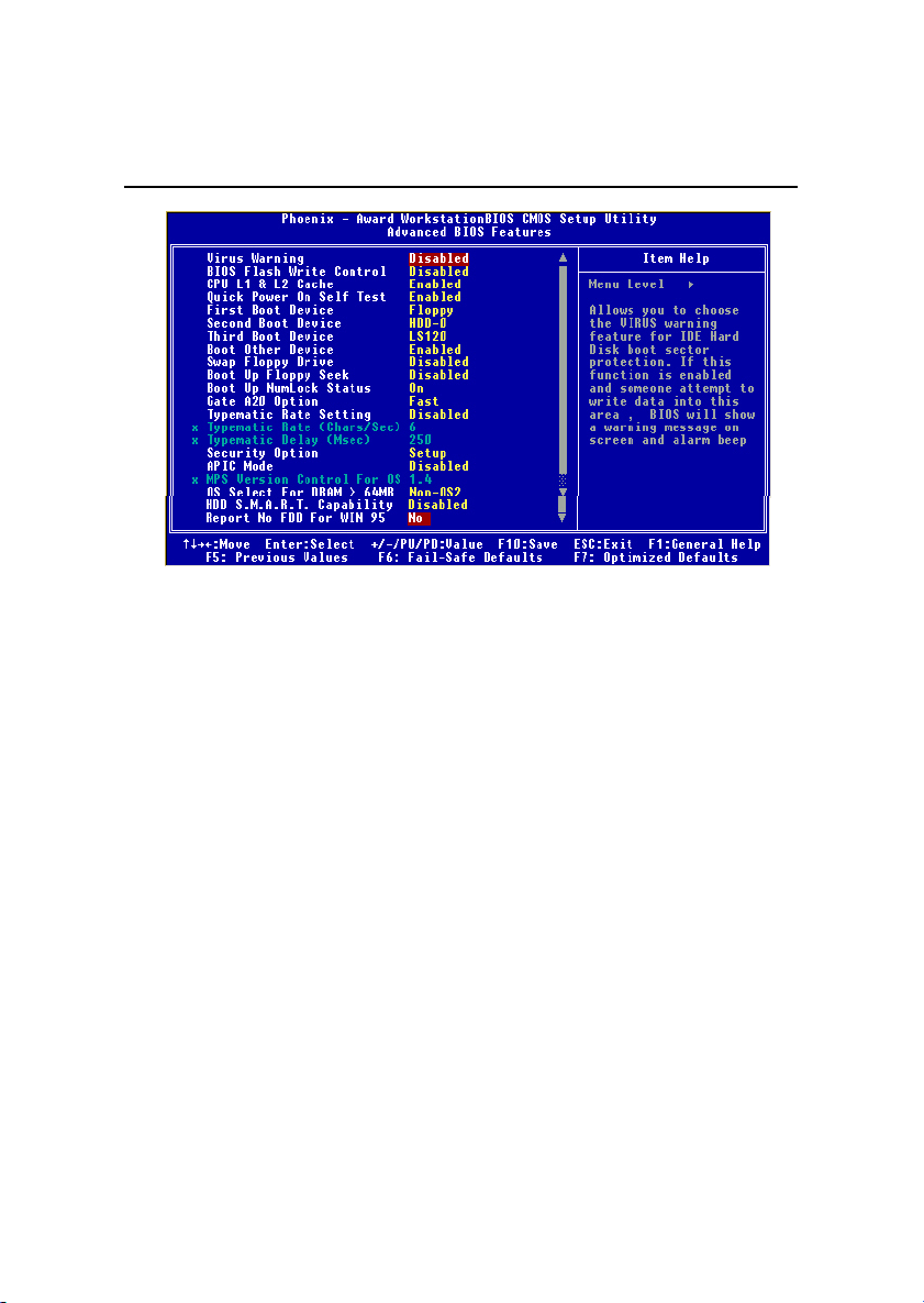
Chapter 3
Advanced BIOS Features
Virus Warning
The setting is to set the virus warning feature for IDE hard disk boot sector
protection. If the function is enabled and any attempt to write data into this
area is made, BIOS will display a warning message on the screen and beep.
Setting options: Disabled, Enabled.
BIOS Flash Write Control
This function protects the BIOS from accidental corruption by unauthorized
users or computer viruses. When disabled, the BIOS' data cannot be changed
when attempting to update the BIOS with a Flash utility. To successfully update the BIOS, you'll need to enable this BIOS Flash Write Control function.
Setting options: Disabled, Enabled.
CPU L1 & L2 Cache
Cache memory is additional memory that is much faster than conventional
DRAM (system memory). When the CPU requests data, the system transfers
the requested data from the main DRAM into cache memory, for even faster
access by the CPU. This setting enables/disables the internal cache (also known
as L1 or level 1 cache) and external cache (also known as L2 or level 2 cache).
Setting options: Disabled, Enabled.
Quick Power On Self Test
The option speeds up Power On Self Test (POST) after you power on the
3-8
Page 85

AWARD® BIOS Setup
computer. When setting the item to Enabled, BIOS will shorten or skip some
check items during POST. Setting options: Enabled, Disabled.
First/Second/Third Boot Device
The items allow you to set the sequence of boot devices where BIOS attempts
to load the disk operating system. The settings are:
Floppy The system will boot from floppy drive.
LS120 The system will boot from LS-120 drive.
HDD-0 The system will boot from the first HDD.
SCSI The system will boot from the SCSI.
CDROM The system will boot from the CD-ROM.
HDD-1 The system will boot from the second HDD.
HDD-2 The system will boot from the third HDD.
HDD-3 The system will boot from the fourth HDD.
ZIP100 The system will boot from ATAPI ZIP drive.
USB-FDD The system will boot from the USB FDD.
USB-ZIP The system will boot from the USB ZIP drive.
USB-CDROM The system will boot from the USB CD-ROM
USB-HDD The system will boot from the USB HDD.
LAN The system will boot from the Network drive.
Disabled Disable this sequence.
Boot Other Device
Setting the option to Enabled allows the system to try to boot from other
device if the system fails to boot from the First/Second/Third boot device.
Swap Floppy Drive
Setting to Enabled will swap floppy drives A: and B:.
Boot Up Floppy Seek
Setting to Enabled will make BIOS seek floppy drive A: before booting the
system. Settings: Disabled and Enabled.
Boot Up NumLock Status
This setting is to set the Num Lock status when the system is powered on.
Setting to On will turn on the Num Lock key when the system is powered on.
Setting to Off will allow users to use the arrow keys on the numeric keypad.
Setting options: On, Off.
3-9
Page 86

Chapter 3
Gate A20 Option
This item is to set the Gate A20 status. A20 refers to the first 64KB of extended
memory. When the default value Fast is selected, the Gate A20 is controlled by
Port92 or chipset specific method resulting in faster system performance. When
Normal is selected, A20 is controlled by a keyboard controller or chipset
hardware.
Typematic Rate Setting
This setting is used to enable or disable the typematic rate setting including
Typematic Rate & Typematic Delay.
Typematic Rate (Chars/Sec)
After Typematic Rate Setting is enabled, this item allows you to set the rate
(characters/second) at which the keys are accelerated. Settings: 6, 8, 10, 12,
15, 20, 24 and 30.
Typematic Delay (Msec)
This item allows you to select the delay between when the key was first pressed
and when the acceleration begins. Settings: 250, 500, 750 and 1000.
Security Option
This specifies the type of BIOS password protection that is implemented. Settings are described below:
Option Description
Setup The password prompt appears only when end users try to
run Setup.
System A password prompt appears every time when the com-
puter is powered on or when end users try to run Setup.
APIC Mode
This field is used to enable or disable the APIC (Advanced Programmable
Interrupt Controller). Due to compliance to PC2001 design guide, the system is
able to run in APIC mode. Enabling APIC mode will expand available IRQs
resources for the system. Settings: Enabled, Disabled.
3-10
Page 87

AWARD® BIOS Setup
MPS Version Control For OS
This field allows you to select which MPS (Multi-Processor Specification)
version to be used for the operating system. You need to select the MPS
version supported by your operating system. To find out which version to
use, consult the vendor of your operating system. Settings: 1.4 and 1.1.
OS Select For DRAM > 64MB
This allows you to run the OS/2® operating system with DRAM greater than
64MB. Setting options: Non-OS2, OS2.
HDD S.M.A.R.T. Capability
This allows you to activate the S.M.A.R.T. (Self-Monitoring Analysis & Reporting Technology) capability for the hard disks. S.M.A.R.T is a utility that
monitors your disk status to predict hard disk failure. This gives you an opportunity to move data from a hard disk that is going to fail to a safe place before
the hard disk becomes offline. Settings: Enabled and Disabled.
Report No FDD For WIN 95
For compatibility with Windows 95 logo certification, select Yes to release IRQ6
when the system contains no floppy drive. When this setting is set to Yes,
users have to select Disabled for the Onboard FDC Controller in the Integrated Peripherals menu. Setting options: Yes, No.
3-11
Page 88
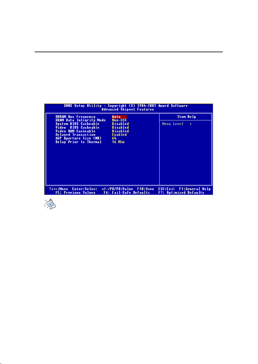
Chapter 3
Advanced Chipset Features
The Advanced Chipset Features Setup option is used to change the values of
the chipset registers. These registers control most of the system options in the
computer.
Choose the “ADVANCED CHIPSET FEATURES” from the Main Menu and
the following screen will appear.
Note: Change these settings only if you are familiar with the chipset.
RDRAM Bus Frequency
This setting allows you to set the bus frequency for installed RDRAM. Setting
options: Auto, 533MHz, 400 MHz, 300 MHz.
DRAM Data Integrity Mode
Select ECC (Error-Checking & Correcting Code) or Non-ECC according to the
type of DRAM installed.
System BIOS Cacheable
Selecting Enabled allows caching of the system BIOS ROM at F0000h-FFFFFh,
resulting in better system performance. However, if any program writes to this
memory area, a system error may result. Setting options: Enabled, Disabled.
Video BIOS Cacheable
Selecting Enabled allows caching of the video BIOS ROM at C0000h to C7FFFh,
resulting in better video performance. However, if any program writes to this
3-12
Page 89

AWARD® BIOS Setup
memory area, a system error may result. Setting options: Enabled, Disabled.
Video RAM Cacheable
Selecting Enabled allows caching of the video memory (RAM) at A0000h to
AFFFFh, resulting in better video performance. However, if any program writes
to this memory area, a memory access error may result. Setting options:
Disabled, Enabled.
Delayed Transaction
The chipset has an embedded 32-bit posted write buffer to support delayed
transactions cycles so that transactions to and from the ISA bus are buffered
and PCI bus can perform other transactions while the ISA transaction is
underway. Select Enabled to support compliance with PCI specification version 2.1. Setting options: Enabled, Disabled.
AGP Aperture Size (MB)
This setting controls just how much system RAM can be allocated to AGP for
video purposes. The aperture is a portion of the PCI memory address range
dedicated to graphics memory address space. Host cycles that hit the aperture
range are forwarded to the AGP without any translation. The option allows the
selection of an aperture size of 4MB, 8MB, 16MB, 32MB, 64MB, 128MB, and
256MB.
Delay Prior to Thermal
When the CPU temperature reaches a factory preset level, a thermal monitoring
mechanism will be enabled following the appropriate timing delay specified in
this field. With the thermal monitoring enabled, clock modulation controlled by
the processor’s internal thermal sensor is also activated to keep the processor
within allowable temperature limit. Setting options: 4 Mins, 8 Mins, 16 Mins,
32 Mins.
3-13
Page 90
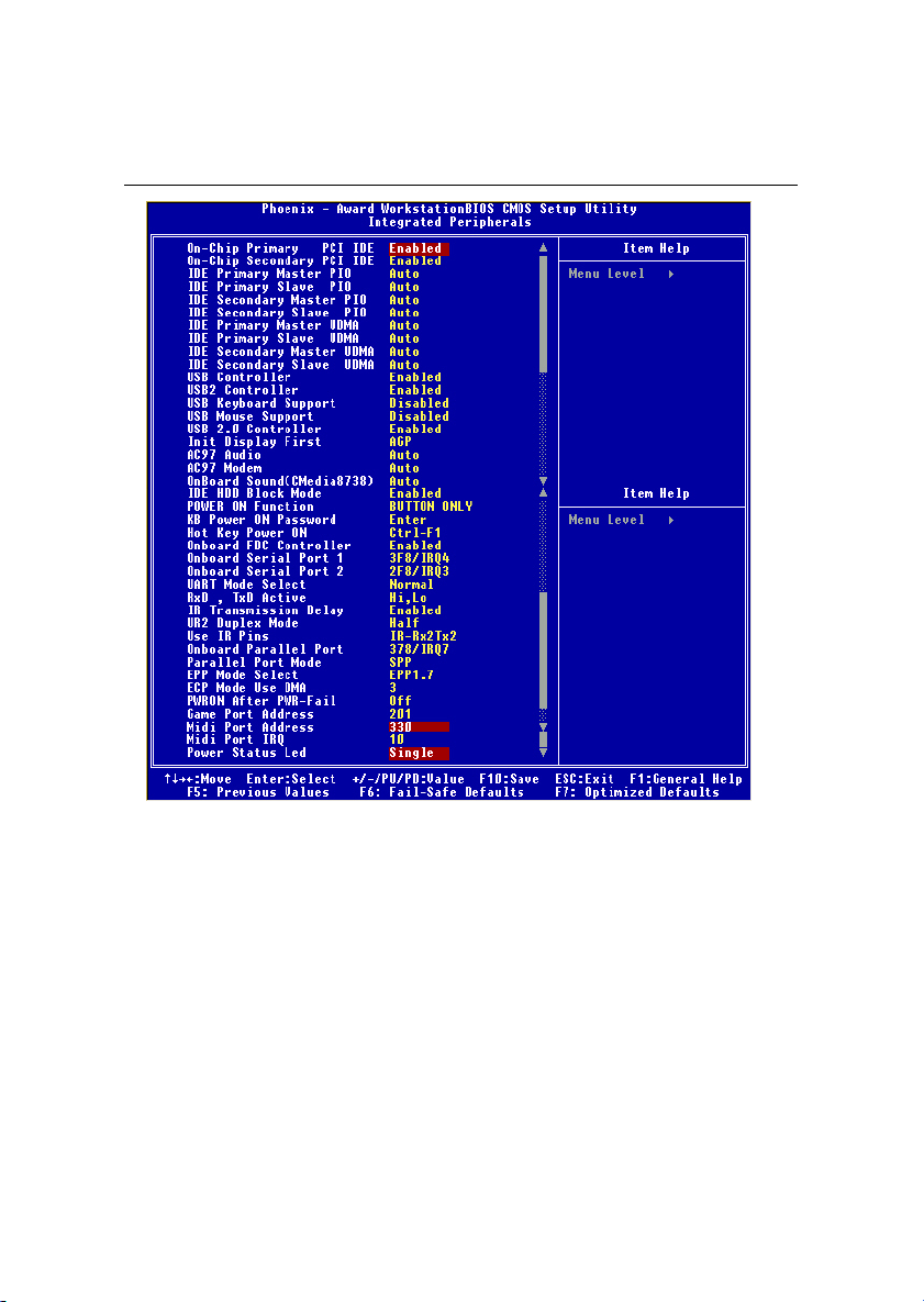
Chapter 3
Integrated Peripherals
On-Chip Primary/Secondary PCI IDE
The integrated peripheral controller contains an IDE interface with support for
two IDE channels. Choose Enabled to activate each channel separately.
IDE Primary/Secondary Master/Slave PIO
The four items allow you to set a PIO (Programmed Input/Output) mode for
each of the four IDE devices that the onboard IDE interface supports. Modes
0~4 provide increased performance. In Auto mode, BIOS automatically determines the best mode for each IDE device.
IDE Primary/Secondary Master/Slave UDMA
Ultra DMA implementation is possible only if your IDE device supports it and
your operating environment contains a DMA driver. If both your hard drive
and software support Ultra DMA 33/66/100, select Auto to enable BIOS support.
3-14
Page 91

AWARD® BIOS Setup
USB/USB2 Controller
Select Enabled if your system contains a Universal Serial Bus (USB) controller
and you have USB peripherals. Setting options: Enabled, Disabled.
USB Keyboard Support
Set to Enabled if your need to use an USB keyboard in the operating system
that does not support or have any USB driver installed, such as DOS and SCO
Unix.
USB Mouse Support
Set to Enabled if your need to use an USB mouse in the operating system that
does not support or have any USB driver installed, such as DOS and SCO Unix.
USB 2.0 Controller
Select Enabled if your system contains a Universal Serial Bus (USB) 2.0
controller and you have USB 2.0 peripherals. Setting options: Enabled,
Disabled.
Init Display First
This item specifies which VGA card is your primary graphics adapter. Settings:
PCI Slot and AGP.
AC’97 Audio
Auto allows the mainboard to detect whether an audio device is used. If the
device is detected, the onboard AC’97 (Audio Codec’97) controller will be
enabled; if not, it is disabled. Disable the controller if you want to use other
controller cards to connect an audio device. Settings: Auto, Disabled.
AC’97 Modem
Auto allows the mainboard to detect whether a modem is used. If a modem is
used, the onboard MC’97 (Modem Codec’97) controller will be enabled; if not,
it is disabled. Disable the controller if you want to use other controller cards to
connect to a modem. Settings: Auto, Disabled.
Onboard Sound (CMedia8738)
This setting enables/disables the onboard sound chip CMedia8738. The
onboard audio controller will be enabled if the device is detected. If you want
to use other controller cards to connect an audio device, diable the controller.
Settings: Auto, Disabled.
3-15
Page 92

Chapter 3
IDE HDD Block Mode
This allows your hard disk controller to use the fast block mode to transfer data
to and from the hard disk drive. Block mode is also called block transfer, multiple commands or multiple sector read/write. Enabled enables IDE controller to
use block mode; Disabled allows the controller to use standard mode.
POWER ON Function
This controls which part on the PS/2 mouse or keyboard can power on the
system. Settings: Password, Hot KEY, Mouse Left, Mouse Right, Any Key,
BUTTON ONLY and Keyboard 98.
KB Power ON Password
If POWER ON Function is set to Password, then you can set a password in the
field for the PS/2 keyboard to power on the system.
Hot Key Power ON
If POWER ON Function is set to Hot KEY, you can assign a hot key combination in the field for the PS/2 keyboard to power on the system. Settings: Ctrl-
F1 through Ctrl-F12.
Onboard FDC Controller
The item is used to enable or disable the onboard Floppy controller. Select
Enabled when you have installed a floppy disk drive and want to use it.
Onboard Serial Port 1/2
The items specify the base I/O port address and IRQ for the onboard Serial Port
A/Serial Port B. Selecting Auto allows BIOS to automatically determine the
correct base I/O port address. Settings: Disabled, 3F8/IRQ4, 2F8/IRQ3, 3E8/
IRQ4, 2E8/IRQ3 and Auto.
UART Mode Select
The field allows you to specify the operation mode for serial port “COM B”.
Settings are:
Normal:RS-232C Serial Port
IrDA: IrDA-compliant Serial Infrared Port
ASKIR: Amplitude Shift Keyed Infrared Port
RxD, TxD Active
This setting controls the receiving and transmitting speed of the IR peripheral
3-16
Page 93

AWARD® BIOS Setup
in use. Setting options: Hi/Hi, Hi/Lo, Lo/Hi, Lo/Lo.
IR Transmission Delay
This setting determines whether the IR transmission rate will be delayed while
converting to receiving mode. Setting options: Disabled, Enabled.
UR2 Duplex Mode
This setting controls the operating mode of IR transmission/reception. Setting
options: Full, Half. Under Full Duplex mode, synchronous, bi-directional trans-
mission/reception is allowed. Under Half Duplex mode, only asynchronous, bidirectional transmission/reception is allowed.
Use IR Pins
Please consult your IR peripheral documentation to select the correct setting
of the TxD and RxD signals. Setting options: RxD2/TxD2, IR-Rx2Tx2.
Onboard Parallel Port
This specifies the I/O port address and IRQ of the onboard parallel port. Settings:
378/IRQ7, 278/IRQ5, 3BC/IRQ7 and Disabled.
Parallel Port Mode
SPP : Standard Parallel Port
EPP : Enhanced Parallel Port
ECP : Extended Capability Port
ECP + EPP: Extended Capability Port + Enhanced Parallel Port
SPP/EPP/ECP/ECP+EPP/Normal
To operate the onboard parallel port as Standard Parallel Port only, choose
“SPP.” To operate the onboard parallel port in the EPP mode simultaneously,
choose “EPP.” By choosing “ECP”, the onboard parallel port will operate
in ECP mode only. Choosing “ECP + EPP” will allow the onboard parallel
port to support both the ECP and EPP modes simultaneously.
EPP Mode Select
The onboard parallel port is EPP Spec. compliant, so after the user chooses the
onboard parallel port with the EPP function, the following message will be
displayed on the screen: “EPP Mode Select.” At this time either EPP 1.7 spec or
EPP 1.9 spec can be chosen.
3-17
Page 94

Chapter 3
ECP Mode Use DMA
The ECP mode has to use the DMA channel, so choose the onboard parallel
port with the ECP feature. After selecting it, the following message will appear:
“ECP Mode Use DMA.” At this time, the user can choose between DMA
channel 3 or 1.
PWRON After PWR-Fail
This setting specifies whether your system will reboot after a power failure or
interrupts occurs. Available settins are:
Off Leaves the computer in the power off state.
On Reboots the computer.
Former-Sts Restores the system to the status before power failure or
interrupt occurs.
Game Port Address
This setting disables or assigns an address for the onboard game/midi port.
Settings: Disabled, 201, 209.
Midi Port Address
This setting specifies the base I/O port address for the onboard midi port.
Settings: Disabled, 330, 300, 290.
Midi Port IRQ
This setting specifies which IRQ the midi port will use. Settings: 5, 10.
Power Status Led
This item sets how the system uses Power LED on the case to indicate the
suspend/sleep state. Settings are:
Single The Power LED blinks to indicate the suspend/sleep
state.
Dual The Power LED changes its color to indicate the sus-
pend/sleep state.
3-18
Page 95
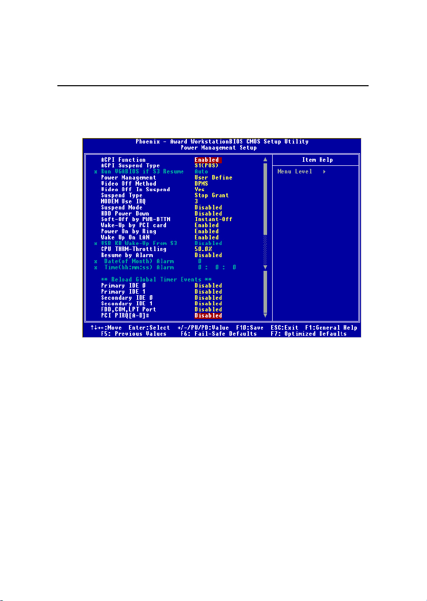
AWARD® BIOS Setup
Power Management Setup
The Power Management Setup allows you to configure you system to most
effectively save energy while operating in a manner consistent with your own
style of computer use.
ACPI Function
This item is to activate the ACPI (Advanced Configuration and Power
Management Interface) Function. If your operating system is ACPI-aware,
such as Windows 98SE/2000/ME, select Enabled. Settings: Enabled and
Disabled.
ACPI Suspend Type
This item specifies the power saving modes for ACPI function. Options are:
S1 (POS) The S1 sleep mode is a low power state. In this state, no
system context (CPU or chipset) is lost and hardware
maintains all system context.
S3 (STR) The S3 sleep mode is a power-down state in which power
is supplied only to essential components such as main
memory and wake-capable devices and all system con-
3-19
Page 96

Chapter 3
text is saved to main memory. The information stored in
memory will be used to restore the PC to the previous
state when an “wake up” event occurs.
Run VGABIOS if S3 Resume
This item allows the system to initialize the VGA BIOS from S3 (Suspend to
RAM) sleep state. Setting options: Auto, Yes, No.
Power Management
This item is used to select the degree (or type) of power saving and is related
to these modes: Suspend Mode and HDD Power Down. There are three options for power management:
User Define Allows end users to configure each mode separately.
Min Saving Minimum Power Management. Suspend Mode = 1 Hour,
and HDD Power Down = 15 Min.
Max Saving Maximum Power Management. Suspend Mode = 1 Min,
and HDD Power Down = 1 Min.
Video Off Method
This determines the manner in which the monitor is blanked.
Blank Screen This option only writes blanks to the video buffer.
V/H SYNC+Blank This selection will cause the system to turn off
the vertical and horizontal synchronization ports
and write blanks to the video buffer.
DPMS Initial display power management signaling.
Video Off In Suspend
This setting determines whether the monitor will be turned off during suspend
mode. Setting options: Yes, No.
Suspend Type
This setting allows you to select the type of Suspend mode. Setting options:
Stop Grant (saves the state of the entire system to disk and then powers off
the system), PwrOn Suspend (the CPU and core system remain powered on in
a very low-power mode).
Modem Use IRQ
Name the interrupt request (IRQ) line assigned to the modem (if any) on your
3-20
Page 97

AWARD® BIOS Setup
system. Activity of the selected IRQ always awakens the system. Settings are
3, 4, 5, 7, 9, 10, 11 and NA.
Suspend Mode
After the selected period of system inactivity, all devices except the CPU shut
off. Settings are Disabled, 1 Min, 2 Min, 4 Min, 8 Min, 12 Min, 20 Min, 30
Min, 40 Min and 1 Hour.
HDD Power Down
If HDD activity is not detected for the length of time specified in this field, the
hard disk drive will be powered down while all other devices remain active.
Settings are Disabled and 1 through 15 Min.
Soft-Off by PWR-BTTN
This feature allows users to configure the power button function. Settings are:
Instant-Off The power button functions as a normal power-on/-
off button.
Delay 4 Sec. When you press the power button, the computer
enters the suspend/sleep mode, but if the button is
pressed for more than four seconds, the computer is
turned off.
Wake Up by PCI Card, Power On by Ring, Wake Up On LAN, USB KB WakeUp From S3
These fields specify whether the system will be awakened from power saving
modes when activity or input signal of the specified hardware peripheral or
component is detected.
Note: To use the function of “Power On by Ring”, you need to install a
modem/LAN card supporting power on function.
CPU THRM-Throttling
The item allows you to specify the CPU speed (at percentage) to which it will
slow down when the CPU reaches the predetermined overheat temperature.
Settings range from 12.5% to 87.5% at 12.5% increment.
Resume by Alarm
The field is used to enable or disable the feature of booting up the system on
a scheduled time/date.
3-21
Page 98

Chapter 3
Date (of Month) Alarm
The field specifies the date for Resume by Alarm. Settings: 0~31.
Time (hh:mm:ss) Alarm
The field specifies the time for Resume by Alarm. Format is <hour>
<minute><second>.
Reload Global Timer Events: Primary IDE 0/1, Secondary IDE 0/1, FDD/
COM/LPT Port, PCI PIRQ [A-D]#
Global Timer Events are I/O events whose occurrence can prevent the system
from entering a power saving mode or can awaken the system from such a
mode. In effect, the system remains alert for anything which occurs to a device
that is configured as Enabled, even when the system is in a power down mode.
3-22
Page 99
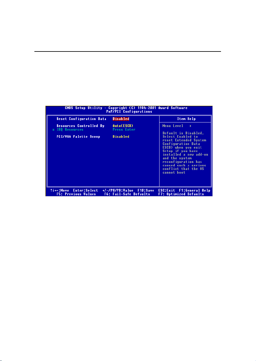
AWARD® BIOS Setup
PNP/PCI Configurations
This section describes configuring the PCI bus system. PCI, or Personal Com-
puter Interconnect, is a system which allows I/O devices to operate at speeds
nearing the speed the CPU itself uses when communicating with its own special components. This section covers some very technical items and it is
strongly recommended that only experienced users should make any changes
to the default settings.
Reset Configuration Data
Normally, you leave this field Disabled. Select Enabled to reset Extended System Configuration Data (ESCD) when you exit Setup if you have installed a
new add-on and the system reconfiguration has caused such a serious conflict
that the operating system can not boot. The settings are: Enabled and Disabled.
Resource Controlled By
The Award Plug and Play BIOS has the capacity to automatically configure all
of the boot and Plug and Play compatible devices. However, this capability
means absolutely nothing unless you are using a Plug and Play operating
system such as Windows 95/98. If you set this field to “manual” choose specific resources by going into each of the sub menu that follows this field (a sub
menu is preceded by a “¾”). The settings are: Auto (ESCD), Manual.
IRQ Resources
The items are adjustable only when Resources Controlled By is set to Manual.
3-23
Page 100

Chapter 3
Press <Enter> and you will enter the sub-menu of the items. IRQ Resources list
IRQ 3/4/5/7/9/10/11/12/14/15 for users to set each IRQ a type depending on the
type of device using the IRQ. Settings are:
PCI Device For Plug & Play compatible devices designed for PCI
bus architecture.
Reserved The IRQ will be reserved for further request.
PCI/VGA Palette Snoop
When set to Enabled, multiple VGA devices operating on different buses can
handle data from the CPU on each set of palette registers on every video
device. Bit 5 of the command register in the PCI device configuration space is
the VGA Palette Snoop bit (0 is disabled). For example, if there are two VGA
devices in the computer (one PCI and one ISA) and the:
VGA Palette Snoop
Bit Setting Action
Disabled Data read or written by the CPU is only directed to the
PCI VGA device’s palette registers.
Enabled Data read or written by the CPU is directed to both the
PCI VGA device’s palette registers and the ISA VGA
device’s palette registers, permitting the palette registers
of both VGA devices to be identical.
The setting must be set to Enabled if any ISA bus adapter in the system
requires VGA palette snooping.
3-24
 Loading...