

Premio Computer Apollo Shadowhawk User Manual

Apollo/Shadowhawk
user manual

Apollo/Shadowhawk
user manual

System Manual

ii Premio System Manual
Copyright
Premio is a registered trademark of Premio Computer, Inc. All other
brands and product names are trademarks or registered trademarks of their
respective companies.
© 1997 by Premio Computer, Inc. All rights reserved.
Printed in Taiwan.
Apollo/Shadowhawk, May 2000.
Disclaimers
Premio makes no representation or warranties, either expressed or
implied, with respect to the contents of this publication and specifically
disclaims the implied warranties of merchantability or fitness for a
particular purpose. Premio shall not be liable for technical or editorial
errors or omissions in this publication, or for incidental or consequential
damages resulting from the furnishing, performance, or use of this
publication. We reserve the right to revise this publication and to make
changes from time to time in its contents without notification.

Getting Started iii
Contents
GETTING STARTED.............................................................. 1
Setting Up ...................................................................................... 2
Switches and Indicators ............................................................... 3
UPGRADING.......................................................................... 5
Opening the System Unit .............................................................6
Installing an Expansion Card....................................................... 7
Installing a Hard Drive ..................................................................8
GETTING HELP ..................................................................... 9
Troubleshooting............................................................................ 9
Monitor Does Not Work...................................................... 9
Keyboard Does Not Work ................................................10
Mouse Does Not Work.....................................................10
System Unit Problems .....................................................11
Hard Drive Problems........................................................ 11
Technical Support.......................................................................12
Premio on the Internet ................................................................ 12

iv Premio System Manual
APPENDIX............................................................................13
Warranty Policy ...........................................................................13
Service Under Warranty...................................................14
Exclusions from Limited Warranty Programs...................14
FCC Standards ............................................................................15
Important Safety Instructions ....................................................16
Getting Started
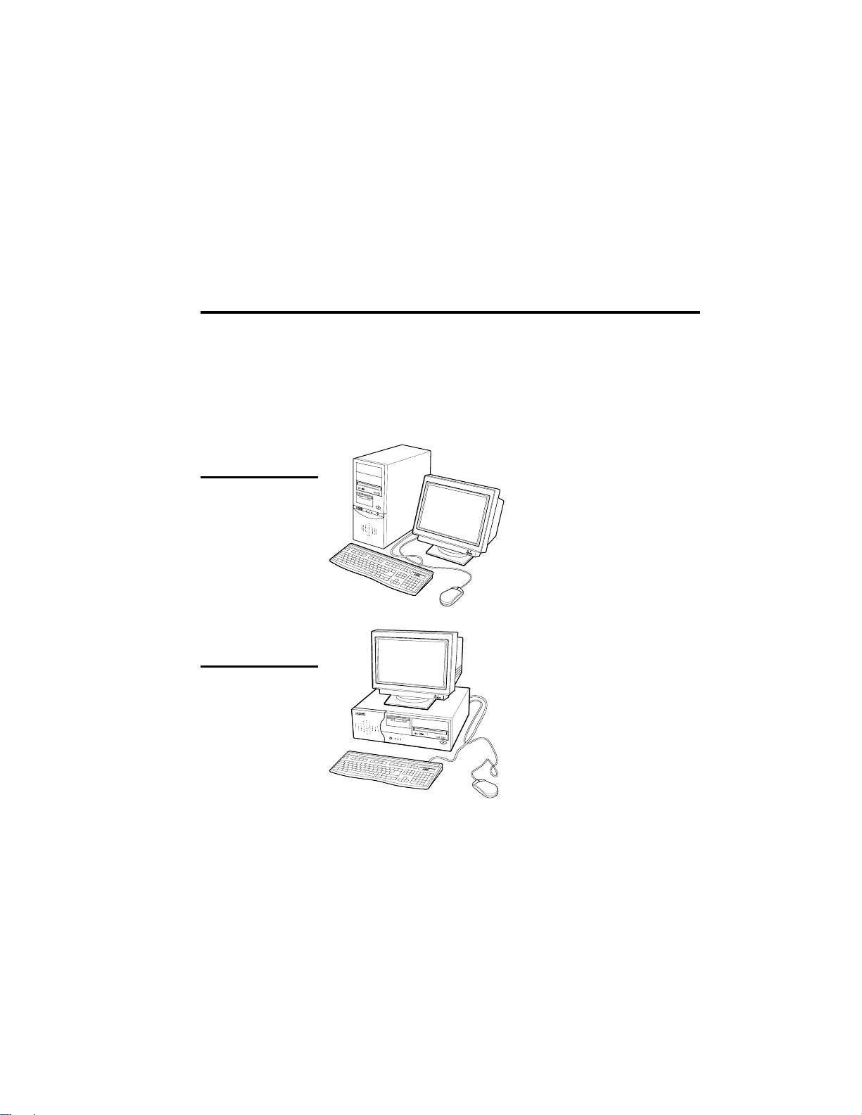
Your Premio® system consists of three components:
a mid-tower or desktop system unit
a keyboard
a mouse
Add your choice of monitor, and your system is ready to use.
System Unit
Mid-tower system
Mouse Keyboard
Desktop system
Keyboard
System Unit
Mouse

2 Premio System Manual
Setting Up
To set up your Premio system, simply connect your monitor, the mouse,
the keyboard, and any additional components you want to use to the
system unit.
Follow these easy steps:
Power Connector
Mouse Connector
Keyboard Connector
USB Connector
Serial-1 Connector
Serial-2 Connector
Parallel Connector
Video Connector
Sound Card Connectors
6
Plug your monitor’s power cord into a power outlet.
7
Attach the female end of the system power cord to the
system unit’s power connector, and then plug the other end
of the cord into a power outlet.
Your Premio system is now ready to use. To start the system, turn on your
monitor’s power switch, and then press the system power switch as shown
on the next page.
1
Attach your monitor’s video cable
to the video connector.
2
Attach the mouse cable to the
mouse connector.
3
Attach the keyboard cable to the
keyboard connector.
4
Attach the cables for any additional
components, such as a printer,
scanner, or modem, to the
respective parallel, serial, or
universal serial bus (USB)
connector, as directed in the
component’s manual.
5
If your system is equipped for
multimedia, attach your speakers
and microphone to the sound card
connectors.

Getting Started 3
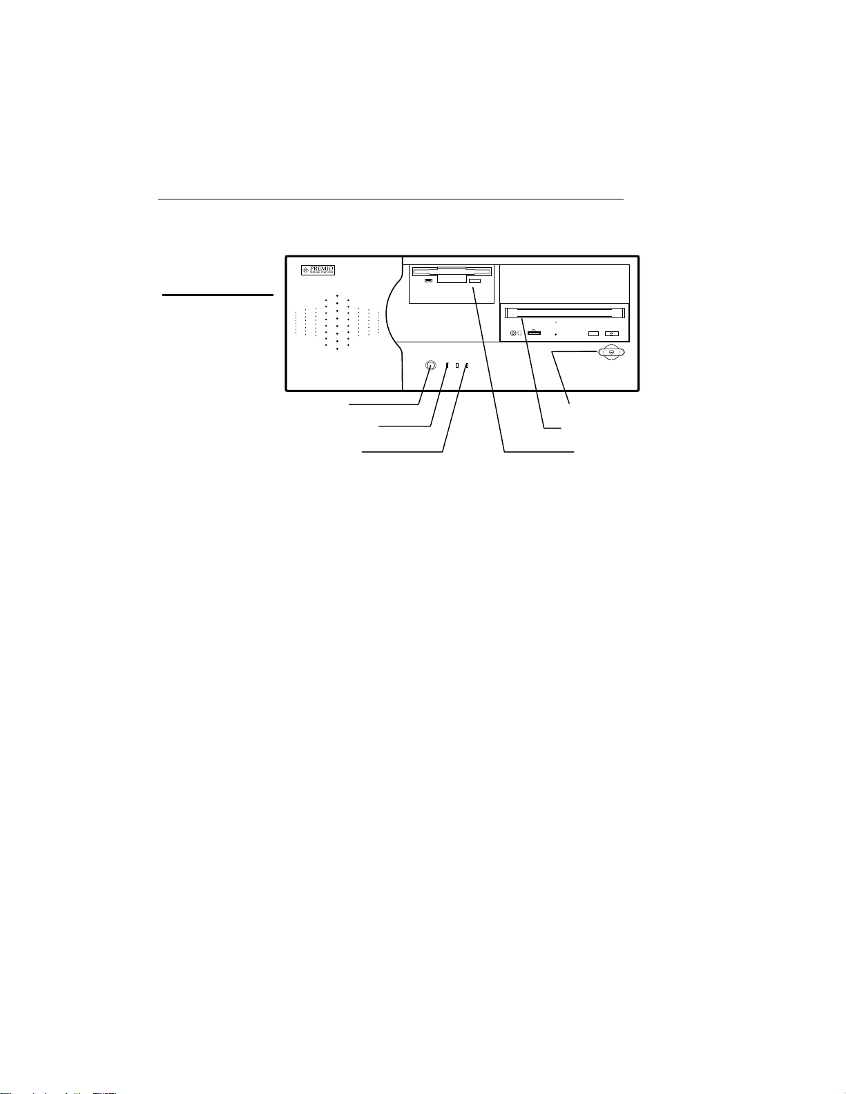
Switches and Indicators
The system unit’s front panel provides access to the CD-ROM and floppy
drives, and to the system’s switches and indicator lights.
The illustration below shows a mid-tower system. If you have a desktop
system, turn to the illustration on the next page.
Mid-tower system
CD ROM Drive
Floppy Drive
Power Switch
Hard Drive
Power Indicator
Reset Button
The CD-ROM drive reads
information on CDs.
The floppy drive reads and
writes information on diskettes.
The power switch turns the
system on and off.
The hard drive indicator lights
when the hard drive is in use.
The power indicator lights
when the system is on.
The reset button restarts the
system.
4 Premio System Manual
Desktop system
Reset Button
Hard Drive Indicator
Power Indicator
The reset button restarts the system.
The hard drive indicator lights when the hard drive is in use.
The power indicator lights when the system is on.
The power switch turns the system on and off.
The CD-ROM drive reads information on CDs.
The floppy drive reads and writes information on diskettes.
Power Switch
CD ROM Drive
Floppy Drive

Upgrading
You can upgrade your Premio system with:
Expansion cards
More memory
An additional hard drive
To install an upgrade, you must open the system unit. Before
proceeding, read the important cautionary note below. Then follow the
steps on the next page.
Caution! Static discharge can cause permanent damage to internal
electronic components of your computer. Always use the following
precautions when working inside the system unit:
Wear a grounding wrist strap (available at most electronics
stores) when handling electronic components.
Do not remove a component from its antistatic packaging until
you are ready to install it.
Keep one hand in contact with the metal system case.
6 Premio System Manual
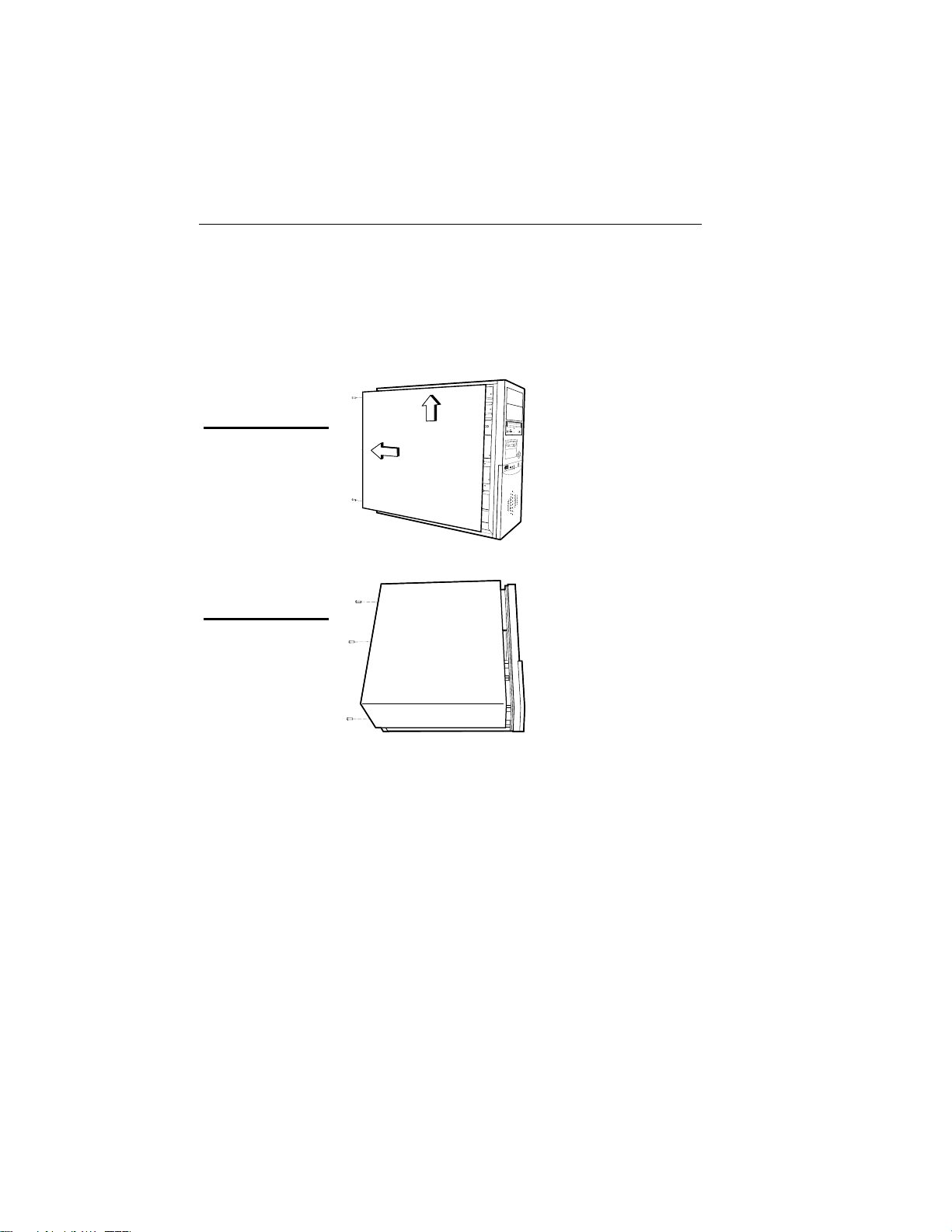
Opening the System Unit
Opening the system unit could affect your warranty. Check with
Note:
the dealer where you purchased your system before opening the
system unit.
To open the system unit, follow these steps:
Mid-tower system
Desktop system
1
Turn off the system and
unplug the power cord.
2
Remove the screws
securing the side panel
(mid-tower) or case
(desktop) at the rear of the
system unit.
3
Slide the side panel or
case up and to the rear,
and remove it.
Upgrading 7
Installing an Expansion Card
To install an expansion card, open the system unit as described on the
previous page. Then follow these steps:
1
Remove the screw
securing the slot bracket
cover for the expansion
slot you want to use. Save
the screw to secure the
expansion card.
2
Insert the expansion card
firmly into the slot,
making sure it is seated
completely.
3
Secure the card with the
saved screw.
8 Premio System Manual
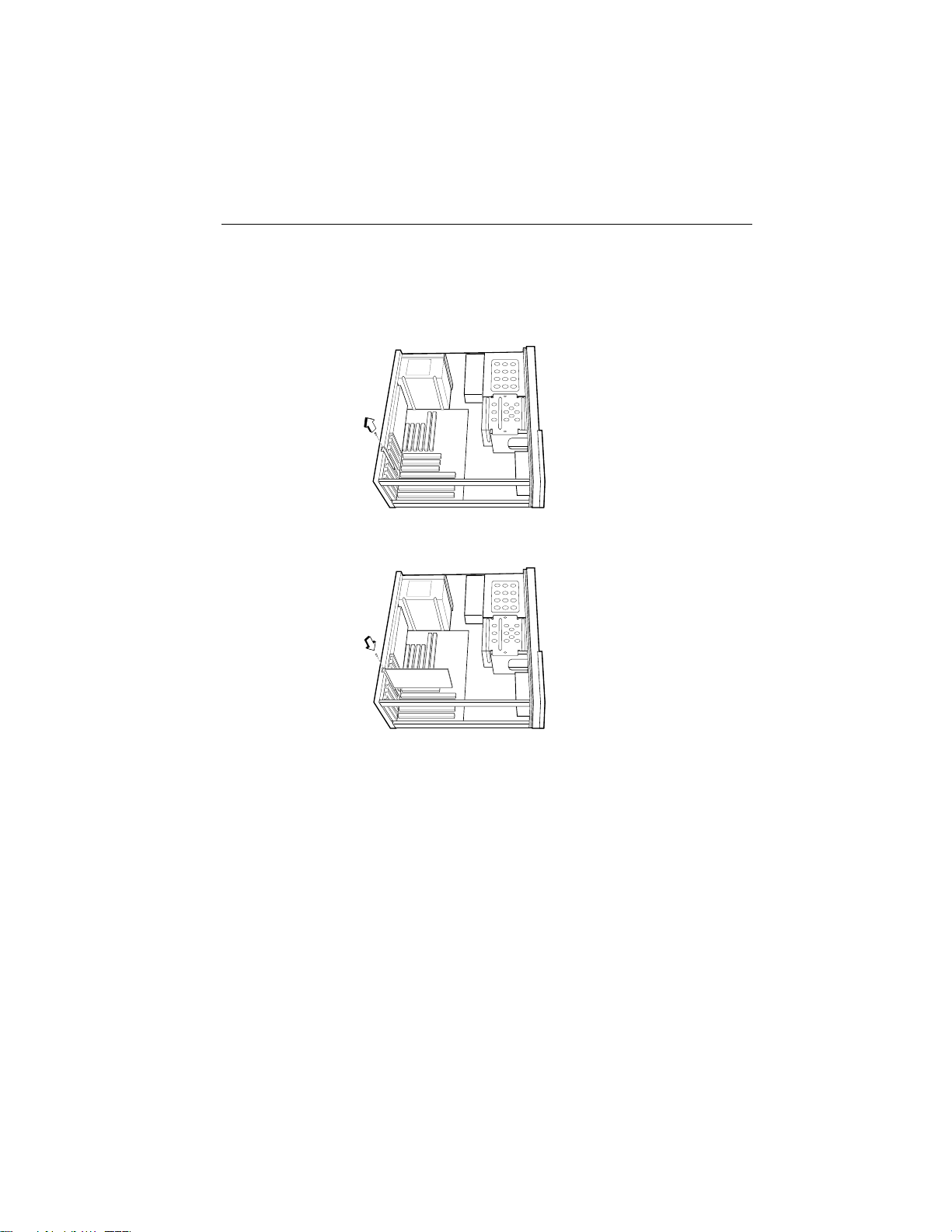
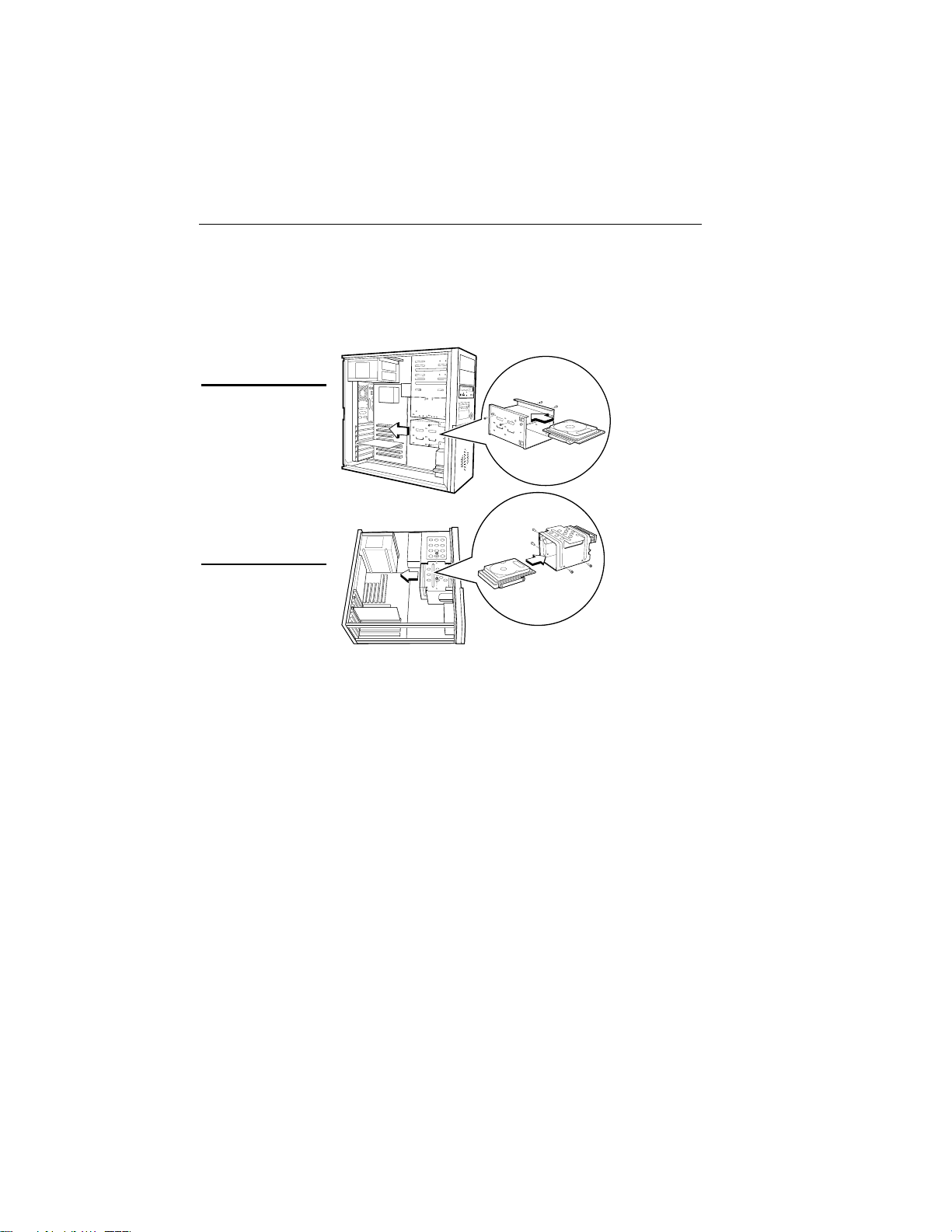
Installing a Hard Drive
To install a hard drive in your system, follow these steps:
1
Disconnect the hard drive cable and power connector.
Mid-tower system
Desktop system
2
Remove the two screws securing the drive bay.
3
Slide the bay toward the rear of the system unit to remove it.
4
Insert the new drive into an open position in the bay and secure
it with four screws.
5
Slide the bay back into the system unit and secure it with two
screws.
6
Connect the cables.

Getting Help
Troubleshooting
Your Premio system is designed to provide years of trouble-free
performance. If you have a problem with your system, you may wish
to check the information in this section for a quick solution.
Monitor Does Not Work
If your monitor appears not to be working properly:
Check that the monitor’s power cable is securely attached to
the monitor and to an outlet that is receiving power.
Check that the monitor’s video cable is securely attached to the
monitor and to the system unit’s video card connector.
Check that the monitor’s power switch is on.
Adjust the monitor’s brightness and contrast controls.
If possible, substitute another monitor that is in good working
order. If the substitute works, your monitor may need repair or
replacement.

10 Premio System Manual
Keyboard Does Not Work
If the NumLock indicator in the upper right corner of the keyboard
does not light when the system powers up, or the keyboard does not
work:
Check that the keyboard cable is securely attached to the
system unit’s keyboard connector.
If possible, substitute another keyboard that is in good working
order. If the substitute works, your keyboard may need
replacement.
Mouse Does Not Work
If your mouse pointer does not move or moves erratically when you
move the mouse:
Check that the mouse cable is securely attached to the mouse
connector on the system unit.
Disassemble the mouse and clean the roller ball.

Getting Help 11
System Unit Problems
The fan inside the system unit should make a low, steady sound
when operating properly.
If the fan is totally silent:
Check that the system power cord is securely attached to the
back of the system unit and to a power outlet. Verify that the
outlet has power.
If possible, substitute another power cord that is in good
working order. If the substitute works, replace your power
cord.
If the fan makes excessive noise:
Turn off the system, open the system unit case, and inspect the
fan for any obstructions.
Turn on the system and listen closely to the fan. If the noise
comes from inside the fan housing, your power supply may
need replacement.
Hard Drive Problems
Your hard drive should make a slight whirring sound when operating
properly.
If the drive is totally silent:
Turn off the system, open the system unit case, and check that
the power cable between the power supply and the hard drive
is securely attached at both ends. If it is, your hard drive may
be defective.
If the hard drive makes excessive noise:
Turn off the system, open the system unit case, and remove the
hard drive power cable connector from the hard drive. Then
turn the system back on. If the noise disappears, your hard
drive may be defective.
If you have more than one hard drive, repeat the same
procedure for each drive.

12 Premio System Manual
Technical Support
You can contact Premio technical support at the following address:
Premio Computer, Inc.
918 Radecki Court
City of Industry, CA 91748
Telephone: 626.839.3100
Fax: 626.839.3191
Email: support@premiopc.com
Web page: http://support.premiopc.com
Premio on the Internet
Premio maintains a web page on the Internet with the latest
information on Premio products, updated drivers, answers to
common problems, a troubleshooting guide, and more. Visit our web
page at:
http://www.premiopc.com

Appendix
Warranty Policy
Premio Computer, Inc. warrants its line of Premio® computer systems to
be free from defects in material and workmanship for a specific warranted
period as stated below, from the date of original purchase from Premio
Computer, Inc. or a Premio Computer, Inc. authorized reseller. This
warranty is contingent upon proper use of the product in question and
does not cover products which have been modified or which have been
subjected to unusual physical or electrical stress. Warranty for third party
hardware and software, if any, is subject to the third party's warranty
policy. Please refer to the following for length of warranty for Premio's
product line.
Premio Product Warranty
Complete Premio System with monitor 3 years parts
and labor
Premio Barebone (with or without CPU) 2 years parts
and labor
Premio Monitor 2 year parts and
labor
Premio OEM Component (motherboard, speaker, case,
keyboard, mouse, floppy drive, CD-ROM, etc.)
2 years parts
and labor

14 Premio System Manual
Service Under Warranty
If this product fails to be in good working order during the warranty
period (or specific period of time as noted above), Premio Computer, Inc.
will, at its option, repair or replace the product. Repair parts and/or
replacement products may be either new or reconditioned at Premio
Computer Inc.'s discretion. The limited warranty does not include service
or repair for damage from improper installation, abuse or modifications to
the product not approved in writing by Premio Computer, Inc. Any
service repair outside the scope of this limited warranty will be at Premio
Computer, Inc.'s or its Authorized Service Provider's rates and terms in
effect. This warranty is valid only within the United States, Puerto Rico,
Canada, Mexico and South America.
Exclusions from Limited Warranty Programs
All other expressed and implied warranties for this product are hereby
disclaimed. If this product is not in good working order as warranted
above, Premio Computer's sole and exclusive remedy shall be repair or
replacement as stated above. In no event will Premio Computer, Inc. be
liable to the customer or any third party for any damages in excess of the
purchase price of the product. This limitation applies to damages of any
kind including any direct or indirect damages, lost profits, lost savings or
other special, incidental or consequential damages. This holds true for
situations even if Premio Computer, Inc. or an authorized Premio
representative or dealer has been advised of the possibility of such
damages or of any claim by another party. Some states do not allow the
exclusion or limitation of incidental or consequential damages for some
products, so the above limitation or exclusion may not apply to you.
Premio Computer, Inc. authorized resellers and service providers/partners
may be changed, added or deleted, without notice or liability. Premio
Computer, Inc. disclaims any authorized resellers and service
provider/partner to the program. This warranty gives you specific legal
rights and you may also have other rights, which may vary from state to
state.

Appendix 15
FCC Standards
This equipment has been tested and found to comply with the limits for a
Class B digital device, pursuant to Part 15 of the FCC Rules. These limits
are designed to provide reasonable protection against harmful interference
in a residential installation. This equipment generates, uses and can
radiate radio frequency energy and, if not installed and used in accordance
with the instructions, may cause harmful interference to radio
communications. However, there is no guarantee that interference will not
occur in a particular installation. If this equipment does cause harmful
interference to radio or television reception, which can be determined by
turning the equipment off and on, the user is encouraged to try to correct
the interference by one or more of the following measures:
Reorient or relocate the receiving antenna.
Increase the separation between the equipment and receiver.
Connect the equipment into an outlet on a circuit different from that
to which the receiver is connected.
Consult the dealer or an experienced radio/TV technician for help.

16 Premio System Manual
Important Safety Instructions
These instructions are provided by Underwriters Laboratories, Inc.
1. Read all of these instructions and save them for later reference.
2. Follow all warnings and instructions marked on the product.
3. Unplug this product from the wall outlet before cleaning. Do not
use liquid or aerosol cleaners. Use a damp cloth for cleaning.
4. Do not use this product near water.
5. Do not place this product on an unstable cart, stand or table. The
product may fall, causing serious damage to the product.
6. Slots and openings on the cabinet and the back or bottom are
provided for ventilation. To ensure reliable operation of the product
and to protect it from overheating, do not block or cover these
openings. The openings should never be blocked by placing the
product on a bed, sofa, rug or other similar surface. This product
should never be placed near or over a radiator or heat register. This
product should not be placed in a built-in installation unless proper
ventilation is provided.
7. This product should be operated from the type of power source
indicated on the marking label. If you are not sure of the type of
power available, consult your dealer or local power company.
8. This product is equipped with a 3-wire grounding-type plug, a plug
having a third (grounding) pin. This plug will only fit into a
grounding-type power outlet. This is a safety feature. If you are
unable to insert the plug into the outlet, contact your electrician to
replace your obsolete outlet. Do not defeat the safety purpose of the
grounding-type plug.
9. Do not allow anything to rest on the power cord. Do not locate this
product where the cord will be walked on.
10. If an extension cord is used with this product, make sure that the
total of the ampere ratings on the products plugged into the
extension cord do not exceed the extension cord ampere rating.
Also, make sure that the total of all products plugged into the wall
outlet does not exceed 15 amperes.
11. Never push objects of any kind into this product through cabinet
slots as they may touch dangerous voltage points or short out parts

Appendix 17
that could result in a risk of fire or electric shock. Never spill liquid
of any kind on the product.
12. Except as explained elsewhere in this manual, don't attempt to
service this product yourself. Opening and removing those covers
that are marked “Do Not Remove” may expose you to dangerous
voltage points or other risks. Refer all servicing on those
compartments to service personnel.
13. Unplug this product from the wall outlet and refer servicing to
qualified service personnel under the following conditions:
A. When the power cord or plug is damaged or frayed.
B. If liquid has been spilled into the product.
C. If the product has been exposed to rain or water.
D. If the product does not operate normally when the operating
instructions are followed. Adjust only those controls that are
covered by the operating instructions since improper
adjustment of other controls may result in damage and will
often require extensive work by a qualified technician to
restore the product to normal operation.
E. If the product has been dropped or the cabinet has been
damaged.
F. If the product exhibits a distinct change in performance,
indicating a need for service.

Intel® Desktop Board
D845HV/D845WN
Technical Product Specification
August 2001
Order Number: A65136-001
The Intel® Desktop Boards D845HV/D845WN may contain design defects or errors known as errata that may cause the product to deviate from published specifications. Current
characterized errata are documented in the Intel Desktop Board D845HV/D845WN Specification Update.

Revision History
Revision Revision History Date
-001 First release of the Intel® Desktop Board D845HV/D845WN Technical
Product Specification.
This product specification applies to only standard D845HV and D845WN boards with BIOS
identifier HV84510A.86A.
Changes to this specification will be published in the Intel Desktop Board D845HV/D845WN
Specification Update before being incorporated into a revision of this document.
INFORMATION IN THIS DOCUMENT IS PROVIDED IN CONNECTION WITH INTEL® PRODUCTS. EXCEPT AS
PROVIDED IN INTEL’S TERMS AND CONDITIONS OF SALE FOR SUCH PRODUCTS, INTEL ASSUMES NO LIABILITY
WHATSOEVER, AND INTEL DISCLAIMS ANY EXPRESS OR IMPLIED WARRANTY, RELATING TO SALE AND/OR USE
OF INTEL PRODUCTS INCLUDING LIABILITY OR WARRANTIES RELATING TO FITNESS FOR A PARTICULAR
PURPOSE, MERCHANTABILITY, OR INFRINGEMENT OF ANY PATENT, COPYRIGHT, OR OTHER INTELLECTUAL
PROPERTY RIGHT.
Intel Corporation may have patents or pending patent applications, trademarks, copyrights, or other intellectual property
rights that relate to the presented subject matter. The furnishing of documents and other materials and information does
not provide any license, express or implied, by estoppel or otherwise, to any such patents, trademarks, copyrights, or other
intellectual property rights.
Intel products are not intended for use in medical, life saving, or life sustaining applications or for any other application in
which the failure of the Intel product could create a situation where personal injury or death may occur.
Intel may make changes to specifications, product descriptions, and plans at any time, without notice.
®
The Intel
product to deviate from published specifications. Current characterized errata are available on request.
Contact your local Intel sales office or your distributor to obtain the latest specifications before placing your product order.
Copies of documents which have an ordering number and are referenced in this document, or other Intel literature, may be
obtained from:
Intel and Pentium are trademarks or registered trademarks of Intel Corporation or its subsidiaries in the United States and
other countries.
†
Copyright 2001, Intel Corporation. All rights reserved.
Desktop Boards D845HV and D845WN may contain design defects or errors known as errata that may cause the
Intel Corporation
P.O. Box 5937
Denver, CO 80217-9808
or call in North America 1-800-548-4725, Europe 44-0-1793-431-155, France 44-0-1793-421-777,
Germany 44-0-1793-421-333, other Countries 708-296-9333.
Other names and brands may be claimed as the property of others.
August 2001

Preface
This Technical Product Specification (TPS) specifies the board layout, components, connectors,
®
power and environmental requirements, and the BIOS for these Intel
and D845WN. It describes the standard product and available manufacturing options.
Intended Audience
The TPS is intended to provide detailed, technical information about the D845HV and D845WN
boards and their components to the vendors, system integrators, and other engineers and
technicians who need this level of information. It is specifically not intended for general
audiences.
What This Document Contains
Chapter Description
1 A description of the hardware used on the D845HV and D845WN boards
2 A map of the resources of the boards
3 The features supported by the BIOS Setup program
4 The contents of the BIOS Setup program’s menus and submenus
5 A description of the BIOS error messages, beep codes, and POST codes
Desktop Boards: D845HV
Typographical Conventions
This section contains information about the conventions used in this specification. Not all of these
symbols and abbreviations appear in all specifications of this type.
Notes, Cautions, and Warnings
NOTE
✏
Notes call attention to important information.
CAUTION
Cautions are included to help you avoid damaging hardware or losing data.
WARNING
Warnings indicate conditions, which if not observed, can cause personal injury.
iii

Intel Desktop Board D845HV/D845WN Technical Product Specification
Other Common Notation
# Used after a signal name to identify an active-low signal (such as USBP0#)
(NxnX) When used in the description of a component, N indicates component type, xn are the relative
coordinates of its location on the D845HV and D845WN boards, and X is the instance of the
particular part at that general location. For example, J5J1 is a connector, located at 5J. It is
the first connector in the 5J area.
GB Gigabyte (1,073,741,824 bytes)
GB/sec Gigabytes per second
KB Kilobyte (1024 bytes)
Kbit Kilobit (1024 bits)
kbits/sec 1000 bits per second
MB Megabyte (1,048,576 bytes)
MB/sec Megabytes per second
Mbit Megabit (1,048,576 bits)
Mbit/sec Megabits per second
xxh An address or data value ending with a lowercase h indicates a hexadecimal value.
x.x V Volts. Voltages are DC unless otherwise specified.
†
This symbol is used to indicate third-party brands and names that are the property of their
respective owners.
iv

Contents
1 Product Description
1.1 Board Differences...................................................................................................... 11
1.2 Overview ...................................................................... Error! Bookmark not defined.
1.2.1 Feature Summary ....................................................................................... 12
1.2.2 Manufacturing Options ................................................................................ 13
1.2.3 Board Layouts............................................................................................. 14
1.2.4 Block Diagram ............................................................................................. 16
1.3 Online Support........................................................................................................... 17
1.4 Operating System Support ........................................................................................ 17
1.5 Design Specifications ................................................................................................ 18
1.6 Processor .................................................................................................................. 21
1.7 System Memory......................................................................................................... 22
®
1.8 Intel
1.9 I/O Controller............................................................................................................. 29
1.10 Audio Subsystem (Optional) ...................................................................................... 32
1.11 LAN Subsystem (Optional) ........................................................................................ 34
1.12 CNR (Optional).......................................................................................................... 35
1.13 Hardware Management Subsystem........................................................................... 36
1.14 Power Management .................................................................................................. 37
845 Chipset...................................................................................................... 24
1.8.1 AGP ............................................................................................................ 25
1.8.2 USB............................................................................................................. 25
1.8.3 IDE Support................................................................................................. 27
1.8.4 Real-Time Clock, CMOS SRAM, and Battery.............................................. 28
®
1.8.5 Intel
82802AB 4 Mbit Firmware Hub (FWH) .............................................. 29
1.9.1 Serial Ports.................................................................................................. 29
1.9.2 Infrared Support .......................................................................................... 30
1.9.3 Parallel Port................................................................................................. 30
1.9.4 Diskette Drive Controller.............................................................................. 31
1.9.5 Keyboard and Mouse Interface ................................................................... 31
1.9.6 I/O Controller Option ................................................................................... 31
1.10.1 Audio Connectors........................................................................................ 33
1.10.2 Audio Subsystem Software ......................................................................... 33
®
1.11.1 Intel
82562ET Platform LAN Connect Device ............................................ 34
1.11.2 RJ-45 LAN Connector with Integrated LEDs ............................................... 34
1.11.3 LAN Subsystem Software............................................................................ 35
1.13.1 Hardware Monitor Component (Optional) .................................................... 36
1.13.2 Fan Monitoring ............................................................................................ 36
1.13.3 Chassis Intrusion and Detection .................................................................. 37
1.14.1 ACPI............................................................................................................ 37
1.14.2 Hardware Support ....................................................................................... 41
v

Intel Desktop Board D845HV/D845WN Technical Product Specification
2 Technical Reference
2.1 Introduction................................................................................................................ 47
2.2 Memory Map ............................................................................................................. 47
2.3 I/O Map .................................................................................................................... 48
2.4 DMA Channels .......................................................................................................... 50
2.5 PCI Configuration Space Map ................................................................................... 50
2.6 Interrupts ...................................................................................................................51
2.7 PCI Interrupt Routing Map ......................................................................................... 51
2.8 Connectors ................................................................................................................ 53
2.8.1 Back Panel Connectors............................................................................... 54
2.8.2 Internal I/O Connectors ............................................................................... 57
2.8.3 External I/O Connectors .............................................................................. 70
2.9 Jumper Blocks........................................................................................................... 74
2.9.1 Front Panel Audio Connector/Jumper Block................................................ 74
2.9.2 BIOS Setup Configuration Jumper Block..................................................... 75
2.10 Mechanical Considerations........................................................................................ 76
2.10.1 D845HV Form Factor .................................................................................. 76
2.10.2 D845WN Form Factor ................................................................................. 77
2.10.3 I/O Shield .................................................................................................... 78
2.11 Electrical Considerations ........................................................................................... 80
2.11.1 Power Consumption.................................................................................... 80
2.11.2 Add-in Board Considerations....................................................................... 80
2.11.3 Standby Current Requirements ................................................................... 81
2.11.4 Fan Connector Current Capability ............................................................... 82
2.11.5 Power Supply Considerations...................................................................... 82
2.12 Thermal Considerations............................................................................................. 83
2.13 Reliability................................................................................................................... 85
2.14 Environmental............................................................................................................ 85
2.15 Regulatory Compliance ............................................................................................. 86
2.15.1 Safety Regulations ...................................................................................... 86
2.15.2 EMC Regulations ........................................................................................ 86
2.15.3 Product Certification Markings (Board Level) .............................................. 87
3 Overview of BIOS Features
3.1 Introduction................................................................................................................ 89
3.2 BIOS Flash Memory Organization ............................................................................. 90
3.3 Resource Configuration ............................................................................................. 90
3.3.1 PCI Autoconfiguration ................................................................................. 90
3.3.2 PCI IDE Support.......................................................................................... 90
3.4 System Management BIOS (SMBIOS) ...................................................................... 91
3.5 Legacy USB Support ................................................................................................. 91
3.6 BIOS Updates............................................................................................................ 92
3.6.1 Language Support....................................................................................... 93
3.6.2 Custom Splash Screen................................................................................ 93
3.7 Recovering BIOS Data .............................................................................................. 93
vi

3.8 Boot Options.............................................................................................................. 94
3.8.1 CD-ROM and Network Boot ........................................................................ 94
3.8.2 Booting Without Attached Devices .............................................................. 94
®
3.9 Fast Booting Systems with Intel
Rapid BIOS Boot ................................................... 94
3.9.1 Peripheral Selection and Configuration ....................................................... 94
3.9.2 Intel Rapid BIOS Boot ................................................................................. 95
3.10 BIOS Security Features............................................................................................. 96
4 BIOS Setup Program
4.1 Introduction................................................................................................................ 97
4.2 Maintenance Menu .................................................................................................... 98
4.2.1 Extended Configuration Submenu............................................................... 99
4.3 Main Menu............................................................................................................... 100
4.4 Advanced Menu....................................................................................................... 101
4.4.1 PCI Configuration Submenu...................................................................... 102
4.4.2 Boot Configuration Submenu .................................................................... 103
4.4.3 Peripheral Configuration Submenu............................................................ 104
4.4.4 IDE Configuration Submenu...................................................................... 106
4.4.5 Diskette Configuration Submenu............................................................... 109
4.4.6 Event Log Configuration Submenu............................................................ 110
4.4.7 Video Configuration Submenu................................................................... 111
4.5 Security Menu.......................................................................................................... 112
4.6 Power Menu ............................................................................................................ 113
4.6.1 ACPI Submenu ......................................................................................... 114
4.7 Boot Menu ............................................................................................................... 115
4.7.1 Boot Device Priority Submenu................................................................... 116
4.7.2 Hard Disk Drives Submenu ....................................................................... 117
4.7.3 Removable Devices Submenu .................................................................. 117
4.7.4 ATAPI CD-ROM Drives Submenu............................................................. 118
4.8 Exit Menu ................................................................................................................ 119
Contents
5 Error Messages and Beep Codes
5.1 BIOS Error Messages.............................................................................................. 121
5.2 Port 80h POST Codes............................................................................................. 123
5.3 Bus Initialization Checkpoints .................................................................................. 127
5.4 Speaker (Optional) .................................................................................................. 128
5.5 BIOS Beep Codes ................................................................................................... 128
Figures
1. D845HV Board Components ..................................................................................... 14
2. D845WN Board Components .................................................................................... 15
3. Block Diagram ........................................................................................................... 16
4. Intel 845 Chipset Block Diagram................................................................................ 24
5. USB Port Configuration for Boards with the SMSC LPC47M142
I/O Controller............................................................................................................. 26
6. USB Port Configuration for Boards with the SMSC LPC47M132
I/O Controller............................................................................................................. 27
7. Audio Subsystem Block Diagram............................................................................... 32
vii
 Loading...