

PR electronics 9410 Series, 9410QI01, 9410QF01, 9410QB01, 9410QA01 Installation Drawings [en, de, pt]
Page 1
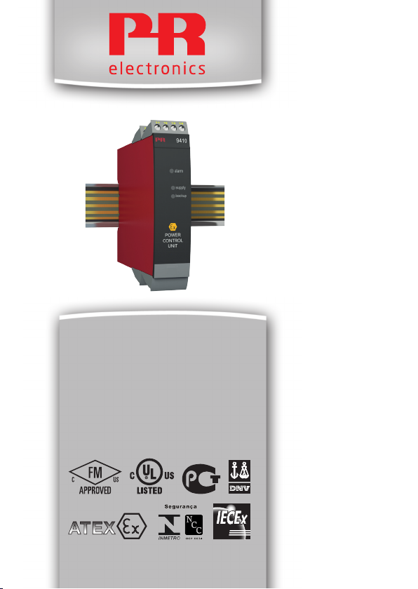
9410
Power Control Unit
Nr. 9410V101-DE
Produktversion: 9410-001
Page 2

PR electronics A/S tilbyder et bredt program af analoge og digitale
DK
signalbehandlingsmoduler til industriel automation. Programmet
består af Isolatorer, Displays, Ex-barrierer, Temperaturtransmittere,
Universaltransmittere mfl. Vi har modulerne, du kan stole på i selv
barske miljøer med elektrisk støj, vibrationer og temperaturudsving,
og alle produkter opfylder de strengeste internationale standarder.
Vores motto »Signals the Best« er indbegrebet af denne filosofi – og
din garanti for kvalitet.
PR electronics A/S oers a wide range of analogue and digital
UK
signal conditioning devices for industrial automation. The product
range includes Isolators, Displays, Ex Interfaces, Temperature
Transmitters, and Universal Devices. You can trust our products in
the most extreme environments with electrical noise, vibrations and
temperature fluctuations, and all products comply with the most
exacting international standards. »Signals the Best« is the epitome
of our philosophy – and your guarantee for quality.
PR electronics A/S ore une large gamme de produits pour le
FR
traite ment des signaux analogiques et numériques dans tous
les domaines industriels. La gamme de produits s’étend des
transmetteurs de température aux acheurs, des isolateurs aux
interfaces SI, jusqu’aux modules universels. Vous pouvez compter
sur nos produits même dans les conditions d’utilisation sévères,
p.ex. bruit électrique, vibrations et fluctuations de température.
Tous nos produits sont conformes aux normes internationales les
plus strictes. Notre devise »SIGNALS the BEST« c’est notre ligne
de conduite - et pour vous l’assurance de la meilleure qualité.
PR electronics A/S verfügt über ein breites Produktprogramm an
DE
analogen und digitalen Signalverarbeitungsmodule für die industrielle Automatisierung. Dieses Programm umfasst Displays,
Temperaturtransmitter, Ex- und galvanische Signaltrenner, und
Universalgeräte. Sie können unsere Geräte auch unter extremen
Einsatzbedingungen wie elektrisches Rauschen, Erschütterungen
und Temperaturschwingungen vertrauen, und alle Produkte von
PR electronics werden in Überein stimmung mit den strengsten
internationalen Normen produziert. »Signals the Best« ist Ihre
Garantie für Qualität!
1341
Page 3

POWER CONTROL UNIT
9410
INHALTSVERZEICHNIS
Warnung ..................................................................................................... 2
Zeichenerklärungen ............................................................................... 2
Sicherheitsregeln .................................................................................... 2
Zerlegung des Systems 9000 ........................................................... 4
Verwendung und erweiterte Merkmale ........................................ 5
Technische Merkmale ............................................................................ 5
Bestellangaben ........................................................................................ 7
Elektrische Daten ................................................................................... 7
Anschlüsse ................................................................................................ 9
Blockdiagramm ......................................................................................... 10
Appendix .................................................................................................... 11
IECEx Installation Drawing............................................................. 12
ATEX Installation Drawing ............................................................. 15
FM Installation Drawing .................................................................. 18
INMETRO Installation Drawing ..................................................... 21
9410 - Product Version 9410-001 1
Page 4
Die folgende Maßnahmen sollten nur in spannungslosem Zustand
des Gerätes und unter ESD-sicheren Verhältnisse durchgeführt
werden:
Installation, Montage und Demontage von Leitungen.
Fehlersuche im Gerät.
Reparaturen des Gerätes und Austausch von Sicherungen dürfen nur von PR electronics A/S vorgenommen werden.
ZEICHENERKLÄRUNGEN
WARNUNG
Dreieck mit Ausrufungszeichen: Das Handbuch ist sorgfältig durch-
zulesen vor Montage und Inbetriebnahme des Gerätes, um schweren
Verletzungen oder mechanischer Zerstörung zu vermeiden.
Die CE-Marke ist das sichtbare Zeichen dafür, dass das Gerät die Vorschriften erfüllt.
Doppelte Isolierung ist das Symbol dafür, dass das Gerät besondere
Anforderungen an die Isolierung erfüllt.
Ex-Geräte sind entsprechend der ATEX Direktive für die Verwendung in Verbindung mit Installationen in explosionsgefährdeter Umgebung zuge lassen.
SICHERHEITSREGELN
DEFINITIONEN
Gefährliche Spannungen sind definitionsgemäß die Bereiche: 75...1500 Volt
Gleichspannung und 50...1000 Volt Wechselspannung.
Techniker sind qualifizierte Personen, die dazu ausgebildet oder angelernt sind,
eine Installation, Bedienung oder evtl. Fehlersuche auszuführen, die sowohl
technisch als auch sicherheitsmäßig vertretbar ist.
Bedienungspersonal sind Personen, die im Normalbetrieb mit dem Produkt die
Drucktasten oder Potentiometer des Produktes einstellen bzw. bedienen und die
mit dem Inhalt dieses Handbuches vertraut gemacht wurden.
EMPFANG UND AUSPACKEN
Packen Sie das Gerät aus, ohne es zu beschädigen und kontrollieren Sie, ob der
Gerätetyp Ihrer Bestellung entspricht. Die Ver packung sollte beim Gerät bleiben,
bis dieses am endgültigen Platz montiert ist.
2 9410 - Product Version 9410-001
Page 5

UMGEBUNGSBEDINGUNGEN
Direkte Sonneneinstrahlung, starke Staubentwicklung oder Hitze, mechanische
Erschütterungen und Stöße sind zu vermeiden; das Gerät darf nicht Regen oder
starker Feuchtigkeit ausgesetzt werden. Bei Bedarf muss eine Erwärmung, welche die angegebenen Grenzen für die Umgebungstemperatur überschreitet, mit
Hilfe eines Kühlgebläses verhindert werden.
Alle Geräte gehören der Installationskategorie II, dem Verschmutzungsgrad 1 und
der Isolationsklasse II an.
Das Gerät ist so konzipiert, dass es auch in einer Einsatzhöhe von bis zu 2 000 m
noch sicher funktioniert.
INSTALLATION
Das Gerät darf nur von Technikern angeschlossen werden, die mit den technischen Ausdrücken, Warnungen und Anweisungen im Handbuch vertraut sind und
diese befolgen.
Sollten Zweifel bezüglich der richtigen Handhabung des Gerätes bestehen, sollte
man mit dem Händler vor Ort Kontakt aufnehmen. Sie können aber auch direkt
mit PR electronics GmbH, www.prelectronics.de Kontakt aufnehmen.
Die Installation und der Anschluss des Gerätes haben in Übereinstimmung mit
den geltenden Regeln des jeweiligen Landes bzw. der Installation elektrischer
Apparaturen zu erfolgen, u.a. bezüglich Leitungsquerschnitt, (elektrischer) VorAbsicherung und Positionierung.
Der Einsatz von Litzendraht an das Versorgungsnetz ist nicht erlaubt außer die
Enden sind mit Aderendhülsen versehen.
Eine Beschreibung von Eingangs- / Ausgangs- und Versorgungsanschlüssen
befindet sich auf dem Blockschaltbild und auf dem seitlichen Schild.
Das Gerät ist mit Feldverdrahtungsklemmen ausgestattet und wird von einem
Netzteil mit doppelter / verstärkter Isolierung versorgt. Der Netzschalter sollte
leicht zugänglich und in der Nähe des Gerätes sein. Der Netzschalter sollte mit
einem Schild gekennzeichnet sein, auf dem steht, dass durch Betätigung dieses
Schalters das Gerät vom Netz genommen wird.
Die ersten beiden Ziffern der Seriennummer geben das Produktionsjahr an.
9410 - Product Version 9410-001 3
Page 6
KALIBRIERUNG UND JUSTIERUNG
Während der Kalibrierung und Justierung sind die Messung und der Anschluss
externer Spannungen entsprechend diesem Handbuch auszuführen. Der
Techniker muss hierbei sicherheitsmäßig einwandfreie Werkzeuge und
Instrumente benutzen.
BEDIENUNG IM NORMALBETRIEB
Das Bedienungspersonal darf das Gerät nur dann einstellen oder bedienen, wenn
diese auf vertretbare Weise in Schalttafeln o. ä. fest installiert sind, sodass die
Bedienung keine Gefahr für Leben oder Material mit sich bringt. D. h., es darf
keine Gefahr durch Berührung bestehen, und das Gerät muss so platziert sein,
dass es leicht zu bedienen ist.
REINIGUNG:
Das Gerät darf nur in spannungslosem Zustand mit einem Lappen gereinigt werden, der mit destilliertem Wasser leicht angefeuchtet ist.
HAFTUNG:
In dem Umfang, in welchem die Anweisungen dieses Handbuches nicht
genau eingehalten werden, kann der Kunde PR electronics gegenüber keine
Ansprüche geltend machen, welche ansonsten entsprechend der eingegangenen
Verkaufsvereinbarungen existieren können.
ZERLEGUNG DES SYSTEMS 9000
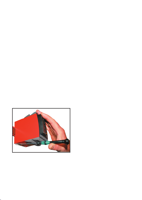
Abbildung 1:
Das Gerät wird von der DIN-Schiene
gelöst, indem man den unteren
Verschluss löst
4 9410 - Product Version 9410-001
Page 7

POWER CONTROL UNIT
9410
• Verteilt die Versorgungsspannung auf die Stromschiene
• Optionaler Anschluss von Backup-Versorgungen
• Zugelassen für den Einbau in Ex-Zone 2 / Div. 2
• Optional redundante Stromversorgung der Stromschiene
• Montage nur auf Power Rail Typ PR 9400
Verwendung und erweiterte Merkmale
• DasPowerControlUnit9410erkenntFehlervonjedemaufderPowerRail
montierten Geräten und sendet einen Sammelalarm an die Steuerung über das
interne Statusrelais.
• OptionalerAnschlussvonzweiNetzteilen-eineprimäreVersorgungundeine
Backup-Versorgung.
• EineredundanteSpannungsversorgungfürdieSammelschienewirddadurch
erreicht, indem zwei 9410 Module mit zwei Netzgeräten (z.B. PR 9420) verdrahtet werden.
Technische Merkmale
• DasStatusrelaiswirdangesteuert(aktiviert-Klemme 11 und 12), wenn die folgenden drei Bedingungen erfüllt sind:
1. Die Versorgungsspannung liegt auf Klemme 31 und 32.
2. Die Backup-Versorgungsspannung liegt auf Klemme 34 und 33. (Wenn die
Backup-Versorgung nicht benötigt wird, muss ein Jumper (Brücke) zwischen
Klemme 32 und Klemme 33 gesetzt werden. Dieser Jumper/Brücke wird zusammen mit dem Gerät geliefert.
3. Es steht keine Fehlermeldung von den auf der Sammelschiene montieren
Geräten an.
• WenneinSammelalarmüberdieSammelschienegemeldetwird,fälltdas
Statusrelais in dem 9410 ab (Klemme 13 und 12).
• ZweigrüneLeuchtdiodeninderFrontleuchtenbeimAnschlussderVersorgung
und der Backup-Versorgung.
• EineroteLeuchtdiodezeigtFehlfunktionenan.
9410 - Product Version 9410-001 5
Page 8
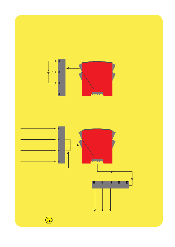
Anwendungen
Geräte-Statusrelais über Sammelschiene
11
N.O.
12
N.C.
13
14
Versorgungsspannungen
Versorgung, Erde
Versorgung, +24 VDC
Backup-Versorgung, +24 VDC
Backup-Versorgung, Erde
31
32
33
34
Wenn die Backup-Versorgung nicht
benötigt wird: Brücke zwischen
Klemme 32 und 33.
Statusrelais-Signal
Rail, +24 VDC
Rail, EErde
Zone 2 / FM Cl. 1, div. 2 oder sicherer Bereich
6 9410 - Product Version 9410-001
Power rail
Page 9

Bestellangaben
9410 = Power control unit
Elektrische Daten
Umgebungstemperatur ......................................... -20...+60°C
Lagertemperatur ...................................................... -20...+85°C
Allgemeine Daten:
Max. Verbrauch ......................................................... 96 W
Wirkungsgrad ............................................................. > 97,9%
Eigenverbrauch, max. . ........................................... 2 W
Leitungsquerschnitt (min. / max.) ..................... 0,13...2,08 mm
Litzendraht
Klemmschraubenanzugsmoment ...................... 0,5 Nm
Luftfeuchtigkeit ....................................................... < 95% RF (nicht kond.)
Abmessungen (HxBxT) ......................................... 109 x 23,5 x 104 mm
Schutzart ..................................................................... IP20
Gewicht ........................................................................ 140 g
Eingang:
Versorgungsspannung,
doppelte / verstärkte Isolierung ........................ 21,6...26,4 VDC
Backup-Versorgung ................................................. 21,6...26,4 VDC
Triggerniveau für Spannungsüberwachung ... Fehler < 21 VDC
Ausgang:
Ausgangsspannung @ 4 A ................................... Eingangsspannung - 0,5 VDC
Ausgangsleistung, max. ........................................ 96 W
Ausgangsstrom, max. ............................................ 4 A
Ausgangswelligkeit ................................................. Selbe als Eingangswelligkeit
Statusrelais im sicheren Bereich:
Max. Spannung ......................................................... 250 / 30 VDC
Max. Strom .................................................................. 2 AAC / 2 ADC
Max. Wechselstromleistung ................................. 500 VA / 60 W
2
/ AWG 26...14
9410 - Product Version 9410-001 7
Page 10

Zulassungen:
EMC 2004/108/EG .................................................. EN 61326-1
LVD 2006/95/EG ...................................................... EN 61010-1
c UL us, Standard for Safety ................................ UL 61010-1
GOST R
Marine:
Det Norske Veritas, Ships & Offshore ............. Stand. f. Certific. No. 2.4
I.S. / Ex:
ATEX 94/9/EG ........................................................... KEMA 07ATEX0152 X
IECEx ............................................................................. IECEx KEM 08.0025X
c FM us ......................................................................... 3034431-C
INMETRO ..................................................................... NCC 12.1308 X
8 9410 - Product Version 9410-001
Page 11
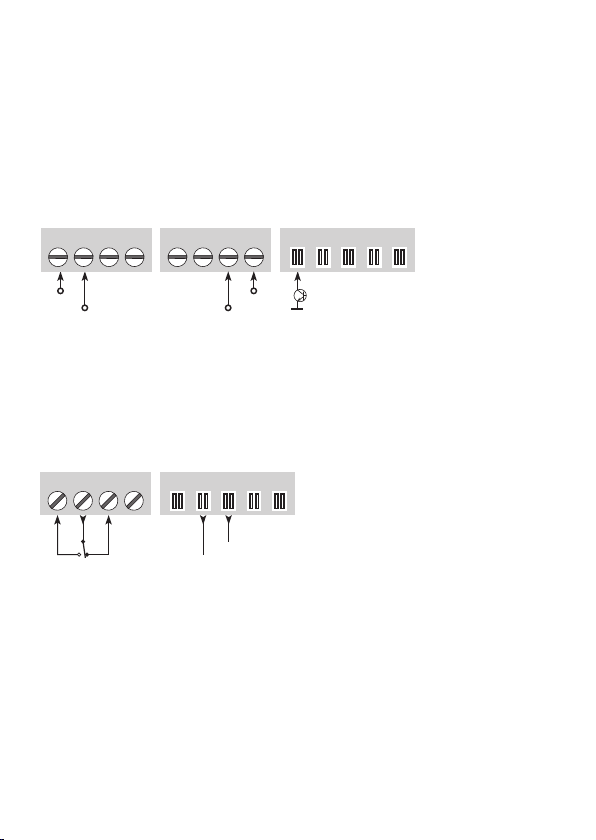
ANSCHLÜSSE
Eingänge:
Versorgungs-
Spannung
Backup-
Versorgung
31 32 33 34 31 32 33 34
Erde Erde
+24 V
Wenn die Backup-Versorgung
nicht benötigt wird: Brücke
zwischen Klemme 32 und 33.
Statusrelais
11 12 13 14
N.C.N.O.
+24 V
Versorgung für
Power Rail
91 92 93 94 95
Erde
+24 V
Gerätestatus
91 92 93 94 95
Fehler
Ausgänge:
9410 - Product Version 9410-001 9
Page 12
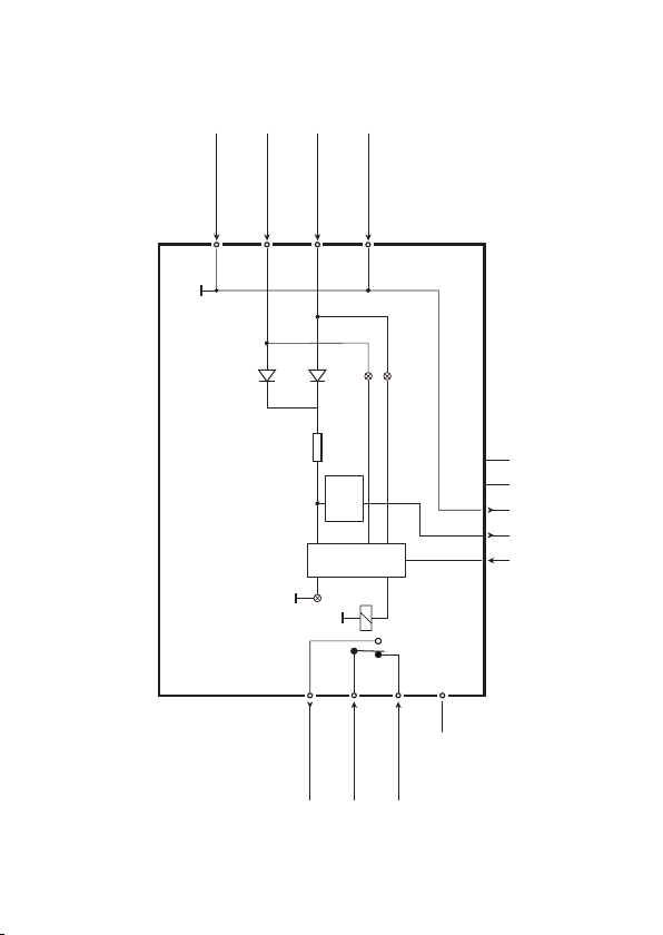
BLOCKDIAGRAMM
Versorgung, +24 VDC
Backup, +24 VDC
Backup, Erde
32
33
34
Grün
Versorgung, Erde
31
Grün
9410
NC = Keine Verbindung
Sicherung
begrenzer
Rød
11
Statusrelais, N.O.
6,3 A
Elektronischer
Strom-
Alarm
12
Statusrelais, gemeinsam
Kollek-
tive
13
14
Statusrelais, N.C.
NC
10 9410 - Product Version 9410-001
NC
NC
Rail, Erde
Rail, +24V
Rail, Status
Page 13

APPENDIX
IECEx Installation drawing
ATEX Installation drawing
FM Installation drawing
INMETRO Installation drawing
9410 - Product Version 9410-001 11
Page 14
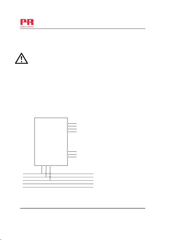
LERBAKKEN 10, 8410 RØNDE DENMARK
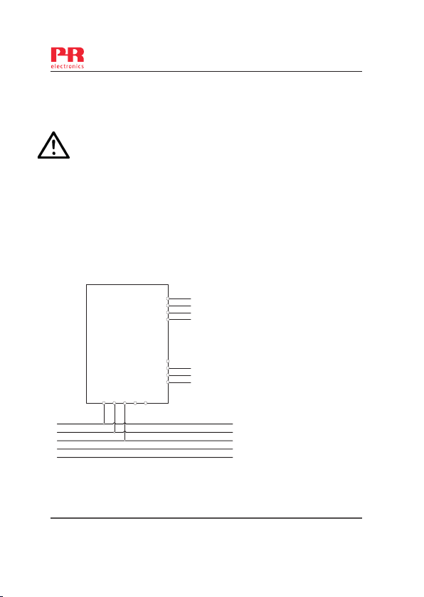
9410QI01
9410
For safe installation of 9410 the following must be observed. The module shall only be
Installed by qualified personnel who are familiar with the national and international laws,
directives and standards that apply to this area.
Year of manufacture can be taken from the first two digits in the serial number.
9410 Power Control Unit
IECEx Certificate KEM 08.0025 X
Marking: Ex nA nC IIC T4 Gc
Standards: IEC60079-0:2007, IEC60079-15:2005
Non Hazardous Area or Zone 2
T4: -20 ºC <Ta < +60ºC
Status
24 V
GND
Revision date:
2009-05-29
IECEx Installation drawing
34
Backup -
33
Backup +
32
Supply +
31
Supply -
14
13
NC
12
COM
11
NO
91 92 93 94 95
9410
Version Revision
V2 R4
Power
Terminal 34-33
Backup: 21,6 VDC – 26,6VDC / 4ADC
Terminal 31-32
Supply: 21,6 VDC – 26,6VDC / 4ADC
Terminal 11, 12, 13
Power Rail Status Relay
Unclassified installation
250VAC, 2A, 500VA / 30VDC, 2A, 60W
Zone 2 installation:
32VAC, 2A, 64VA / 30VDC, 2A, 60W
Rail
Prepared by:
PB
Page:
1/3
12 9410 - Product Version 9410-001
Page 15
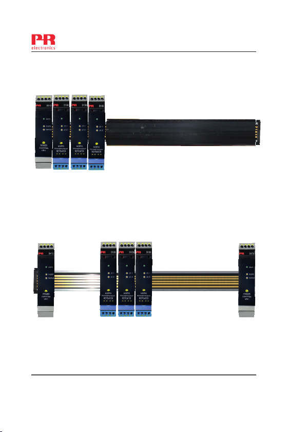
LERBAKKEN 10, 8410 RØNDE DENMARK
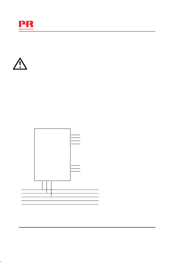
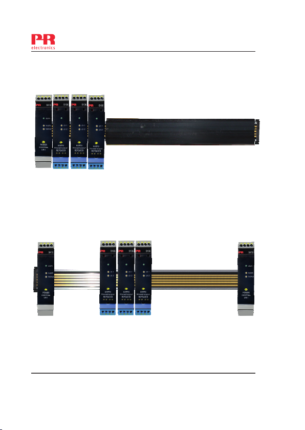
9410 Power Control with backup.
Redundant 9410 Power Control with Backup.
9410QI01
Use Endcaps to prevent
the Power Rail from
being short circuit by the
outer enclosure.
Use 9400 Cover to prevent
open Power Rail from
unintentional short circuit.
Power is supplied to the Power
Rail from two 9410 Power
Control Modules. Both modules
have connections for Normal
Supply and Backup Supply.
Revision date:
2009-05-29
Version Revision
V2 R4
Prepared by:
PB
Page:
2/3
9410 - Product Version 9410-001 13
Page 16
LERBAKKEN 10, 8410 RØNDE DENMARK
Installation notes:
General
The 9410 must be supplied from a Power Source with Double or Reinforced insulation to
Mains.
For installation in Zone 2
The 9410 Power Control Unit and 9400 Power Rail must be installed in an outer
enclosure having an IP protection of at least IP54, conforming to the
requirements of explosion protection Ex-n or Ex-e.
Transients are suppressed by an internal transient protection device, which is
set to a level not exeeding 40% of the rated voltage.
WARNING: Do not separate connectors when energized and an explosive gas
mixture is present.
WARNING: Do not install or remove modules from the Power Rail unless Area
is known to be Non Hazardous.
WARNING:Terminals 91,92,93,94,95 may only be connected to Power Rail
.
9400.
9410QI01
Revision date:
2009-05-29
Version Revision
V2 R4
Prepared by:
PB
14 9410 - Product Version 9410-001
Page:
3/3
Page 17
LERBAKKEN 10, 8410 RØNDE DENMARK
9410QA01
9410
For safe installation of 9410 the following must be observed. The module shall only be
Installed by qualified personnel who are familiar with the national and international laws,
directives and standards that apply to this area.
Year of manufacture can be taken from the first two digits in the serial number.
9410 Power Control Unit
ATEX Certificate KEMA 07ATEX0152 X
Marking: 3G Ex nA nC IIC/IIB/IIA T4
Standard: EN60079-0:2006, EN60079-15:2005
Non Hazardous Area or Zone 2
T4: -20 ºC <Ta < +60ºC
Status
24 V
GND
Revision date:
2008-06-10
ATEX Installation drawing
34
Backup -
33
Backup +
32
Supply +
31
Supply -
14
13
NC
12
COM
11
NO
91 92 93 94 95
9410
Version Revision
V2 R1
Terminal 34-33
Backup: 21,6 VDC – 26,6VDC / 4ADC
Terminal 31-32
Supply: 21,6 VDC – 26,6VDC / 4ADC
Terminal 11, 12, 13
Power Rail Status Relay
Unclassified installation
250VAC, 2A, 500VA / 30VDC, 2A, 60W
Zone 2 installation:
32VAC, 2A, 64VA / 30VDC, 2A, 60W
Power
Rail
Prepared by:
PB
Page:
1/3
9410 - Product Version 9410-001 15
Page 18
LERBAKKEN 10, 8410 RØNDE DENMARK
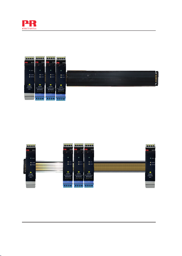
9410 Power Control with backup.
Redundant 9410 Power Control with Backup.
9410QA01
Use Endcaps to prevent
the Power Rail from
being short circuit by the
outer enclosure.
Use 9400 Cover to prevent
open Power Rail from
unintentional short circuit.
Power is supplied to the Power
Rail from two 9410 Power
Control Modules. Both modules
have connections for Normal
Supply and Backup Supply.
Revision date:
2008-06-10
Version Revision
V2 R1
Prepared by:
PB
16 9410 - Product Version 9410-001
Page:
2/3
Page 19
LERBAKKEN 10, 8410 RØNDE DENMARK
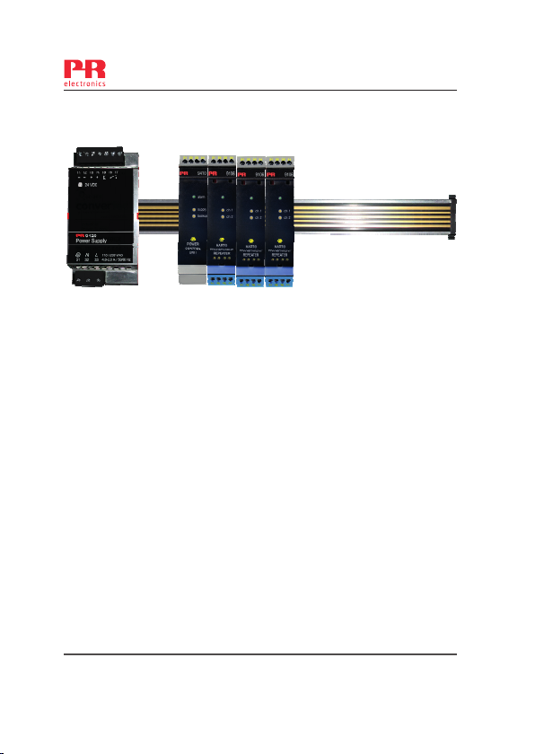
9420 Power Supply and 9410 Power Control with Backup.
Maintain a minimum distance of 50mm
between the 9420 Power Supply and
other modules.
General
The 9410 must be supplied from a Power Source with Double or Reinforced insulation to
Mains.
Alternatively use PR9420 Power Supply for installation inside or outside Zone2.
For installation in Zone 2
The 9410 Power Control Unit and 9400 Power Rail must be installed in an outer
enclosure having an IP protection of at least IP54 conforming to the
requirements of explosion protection Ex-n or Ex-e.
Transients are suppressed by an internal transient protection device, which is
set to a level not exeeding 40% of the rated voltage.
WARNING: Do not separate connectors when energized and an explosive gas
mixture is present.
WARNING: Do not install or remove modules from the Power Rail unless Area
is known to be Non Hazardous.
.
9410QA01
Revision date:
2008-06-10
Version Revision
V2 R1
Prepared by:
PB
Page:
3/3
9410 - Product Version 9410-001 17
Page 20
LERBAKKEN 10, 8410 RØNDE DENMARK
,
9410QF01
9410 Power Control Unit
For safe installation of 9410 the following must be observed. The module shall only be
Installed by qualified personnel who are familiar with the national and international laws,
directives and standards that apply to this area.
c-FM–us Certificate 3034431
Marking NI, Class I, Division 2, Group A,B,C,D T4 or
Class I, Zone2, AEx nA nC IIC T4
Standard: Class 3600,Class 3611, Class 3810, ANSI/ISA 12.00.01 / 12.12.02
ISA 60079-15:2002, CSA-E79-15, CSA-C22.2-213
Non Hazardous Area or Division 2 / Zone 2
T4: -20 ºC <Ta < +60ºC
91 92 93 94 95
Status
24 V
GND
Revision date:
2009-03-30
FM Installation drawing
Class I, Zone2, Ex nA nC IIC T4
34
33
32
31
14
13
12
11
9410
Version Revision
V2 R3
Terminal 34-33
Backup: 21,6 VDC – 26,6VDC / 4ADC
Backup Backup +
Supply +
Terminal 31-32
Supply -
Supply: 21,6 VDC – 26,6VDC / 4ADC
Terminal 11, 12, 13
Power Rail Status Relay
Unclassified installation
NC
250VAC, 2A, 500VA / 30VDC, 2A, 60W
COM
NO
Zone 2 installation:
2A, 64VA / 30VDC, 2A, 60W
32VAC
Power
Rail
Prepared by:
PB
Page:
1/3
18 9410 - Product Version 9410-001
Page 21
LERBAKKEN 10, 8410 RØNDE DENMARK
9410 Power Control with backup.
Redundant 9410 Power Control with Backup.
9410QF01
Use Endcaps to prevent
the Power Rail from
being short circuit by the
outer enclosure.
Use 9400 Cover to prevent
open Power Rail from
unintentional short circuit.
Power is supplied to the Power
Rail from two 9410 Power
Control Modules. Both modules
have connections for Normal
Supply and Backup Supply.
Revision date:
2009-03-30
Version Revision
V2 R3
Prepared by:
PB
Page:
2/3
9410 - Product Version 9410-001 19
Page 22
LERBAKKEN 10, 8410 RØNDE DENMARK
Installation notes:
The installation and wiring shall be in accordance with the Canadian Electrical Code for Canada
and National Electrical Code NFPA 70, Article 500 or 505 for installation in USA.
The module must be supplied from a Power Supply having double or reinforced insulation.
The use of stranded wires is not permitted for mains wiring except when wires are fitted with cable
ends.
For installation in Zone 2 or Division 2, the module must be installed in a suitable outer enclosure
according to the regulations in the CEC for Canada or NEC for USA.
Install in pollution degree 2 or better.
Substitution of components may impair the suitability for division 2 / zone 2 installation.
Warning: To prevent ignition of the explosive atmospheres, disconnect power before servicing and
do not separate connectors when energized and an explosive gas mixture is present.
WARNING: Do not install or remove modules from the Power Rail and do not remove connectors
from the module unless Area is known to be Non Hazardous.
9410QF01
Revision date:
2009-03-30
Version Revision
V2 R3
Prepared by:
PB
20 9410 - Product Version 9410-001
Page:
3/3
Page 23
LERBAKKEN 10, 8410 RØNDE DENMARK
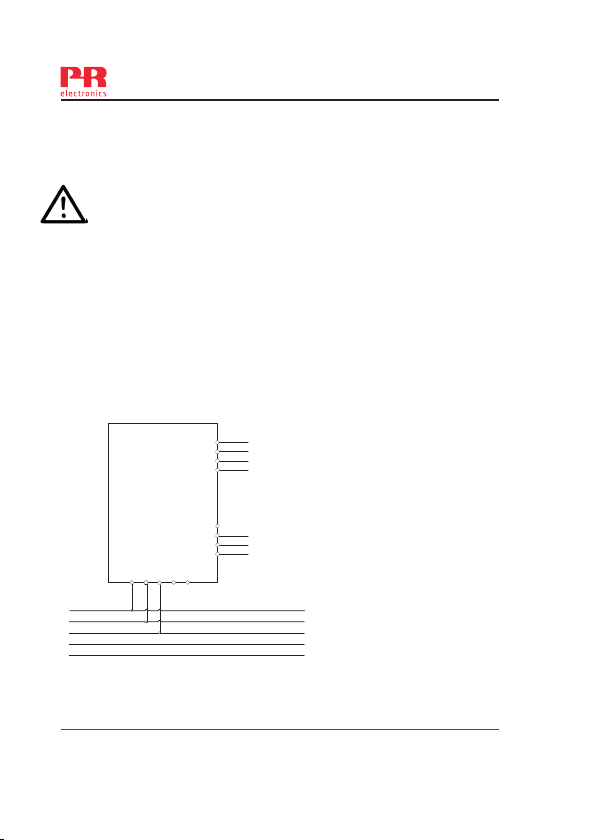
INMETRO Desenhos para Instalação
9410
Para instalação segura do 9410 o manual seguinte deve ser observado. O módulo deve
ser instalado somente por profissionais qualificados que estão familiarizados com as leis
nacionais e internacionais, diretrizes e normas que se aplicam a esta área.
Ano de fabricação pode ser obtido a partir dos dois primeiros dígitos do número de série.
9410 Unidade de Controle de Potência
INMETRO Certificado …… NCC 12.1308X
Marcas: Ex nA nC IIC T4 Gc
Normas IEC60079-0:2011, IEC60079-15:2005
Area de não Risco Area ou Zone 2
T4: -20 ºC <Ta < +60ºC
9410QB01
Terminais 34-33
Fonte reserva: 21,6 VDC – 26,6 VDC / 4 ADC
Fonte reserva Fonte reserva +
Fonte +
Terminais 31-32
Fonte -
Fonte: 21,6 VDC – 26,6 VDC / 4 ADC
Terminal 11, 12, 13
Trilho de Energia Estado
NF
250 VAC, 2 A, 500 VA / 30 VDC, 2 A, 60 W
COM
NA
Area ou Zone 2:
32 VAC, 2 A, 64 VA / 30 VDC, 2 A, 60 W
Prepared by:
PB
Page:
1/3
Estado
24 V
Fonte -
91 92 93 94 95
Revision date:
2013-04-24
34
33
32
31
14
13
12
11
9410
Trilho de Energia
Version Revision
V3 R0
9410 - Product Version 9410-001 21
Page 24

LERBAKKEN 10, 8410 RØNDE DENMARK
9410 Controle de Potência com reserva.
9410QB01
Use Tampas para evitar que o
trilho de alimentação entre em
curto-circuito com invólucro
externo.
Controle de Potencia 9410 redundante com reserva
Revision date:
2013-04-24
Version Revision
V3 R0
Use a capa do 9400 para
prevenir que a abertura do
trilho de energia e causar
curto-circuito não intencional
A energia é fornecida ao barramento de
alimentação de dois módulos de controle de
energia 9410. Ambos os módulos têm
conexões para a fonte de alimentação
normal e a fonte reserva.
Prepared by:
PB
22 9410 - Product Version 9410-001
Page:
2/3
Page 25

LERBAKKEN 10, 8410 RØNDE DENMARK
Notas para Instalação:
Geral
O 9410 deve ser energizado por uma fonte de alimentação com isolamento duplo ou
reforçado vindo da rede elétrica.
Para instalação em Zona 2
O equipamento deve ser instalado dentro de um invólucro certificado conforme
as normas da série ABNT NBR IEC 60079 que forneça no mínimo grau de
proteção IP54.
Transientes são suprimidos por um dispositivo interno, que é definido para um
nível não superior a 40% da tensão nominal.
AVISO: Não separe conectores quando energizado e uma mistura explosiva de
gás estiver presente.
AVISO: Não instalar ou remover os módulos do trilho de energia a menos que
área seja conhecida como não perigoso (não risco).
AVISO: Terminais 91, 92, 93, 94 e 95 só podem ser conectados ao Trilho de
Energia 9400.
9410QB01
Revision date:
2013-04-24
Version Revision
V3 R0
Prepared by:
PB
Page:
3/3
9410 - Product Version 9410-001 23
Page 26
Displays
Displays
selection of inputs and outputs for display of temperature,
selection of inputs and outputs for display of temperature,
volume and weight, etc. Feature linearisation, scaling, and
volume and weight, etc. Feature linearisation, scaling, and
dierence measurement functions for programming via
dierence measurement functions for programming via
PReset software.
PReset software.
Ex interfaces
Ex interfaces
as well as HART
as well as HART
frequency signals and control systems in Ex zone 0, 1 & 2
/ frequency signals and control systems in Ex zone 0, 1 & 2
and for some modules in zone 20, 21 & 22.
and for some modules in zone 20, 21 & 22.
Programmable displays with a wide
Programmable displays with a wide
Interfaces for analogue and digital signals
Interfaces for analogue and digital signals
®
®
signals between sensors / I/P converters /
signals between sensors / I/P converters
Isolation
Isolation
signals as well as HART
signals as well as HART
with both loop-powered and universal isolators featuring
with both loop-powered and universal isolators featuring
linearisation, inversion, and scaling of output signals.
linearisation, inversion, and scaling of output signals.
Temperature
Temperature
form B mounting and DIN rail modules with analogue
form B mounting and DIN rail modules with analogue
and digital bus communication ranging from application-
and digital bus communication ranging from application-
specific to universal transmitters.
specific to universal transmitters.
Universal
Universal
universal options for input, output and supply. This range
universal options for input, output and supply. This range
oers a number of advanced features such as process
oers a number of advanced features such as process
calibration, linearisation and auto-diagnosis.
calibration, linearisation and auto-diagnosis.
Galvanic isolators for analogue and digital
Galvanic isolators for analogue and digital
®
®
signals. A wide product range
signals. A wide product range
A wide selection of transmitters for DIN
A wide selection of transmitters for DIN
PC or front programmable modules with
PC or front programmable modules with
Page 27
www.prelectronics.fr
[email protected]
www.prelectronics.de
[email protected]
www.prelectronics.es
[email protected]
www.prelectronics.it
[email protected]
www.prelectronics.se
[email protected]
www.prelectronics.co.uk
[email protected]
www.prelectronics.com
[email protected]
www.prelectronics.cn
[email protected]
Head oce
Denmark www.prelectronics.com
PR electronics A/S [email protected]
Lerbakken 10 tel. +45 86 37 26 77
DK-8410 Rønde fax +45 86 37 30 85
 Loading...