

Page 1

Programmable displays with a wide selection of inputs and outputs for display of temperature,
volume and weight, etc. Feature linearisation, scaling,
and difference measurement functions for programming
via PReset software.
Interfaces for analogue and digital
signals as well as HART
®
signals between sensors / I/P
converters / frequency signals and control systems in Ex
zone 0, 1 & 2 and for some modules in zone 20, 21 & 22.
Galvanic isolators for analogue and digital
signals as well as HART
®
signals. A wide product range
with both loop-powered and universal isolators featuring
linearisation, inversion, and scaling of output signals.
PC or front programmable modules with
universal options for input, output and supply. This range
offers a number of advanced features such as process
calibration, linearisation and auto-diagnosis.
A wide selection of transmitters for DIN
form B mounting and DIN rail modules with analogue
and digital bus communication ranging from applicationspecifi c to universal transmitters.
Displays
Temperature
Isolation
Ex barriers
Universal
DK
UK
FR
DE
Side 1
Page 17
Page 33
Seite 49
SIGNALS THE BEST
5350
PROFIBUS® PA / FOUNDATION™ Fieldbus Transmitter
No. 5350V109-IN (0825)
From ser. no. 030640001
Page 2

PROFIBUS® PA / FOUNDATION™ FIELDBUS
TRANSMITTER
PRetrans 5350
Indholdsfortegnelse
Sikkerhedsinstruktion ......................................................... 2
EF-overensstemmelseserklæring ....................................... 3
Anvendelse ......................................................................... 4
Teknisk karakteristik ........................................................... 4
Montage / installation ......................................................... 4
Applikationer ...................................................................... 5
Bestillingsskema................................................................. 6
Elektriske specifikationer ................................................... 6
Tilslutninger, indgang ......................................................... 12
Tilslutninger, udgang .......................................................... 13
Montering af følerledninger ................................................ 13
Blokdiagram ....................................................................... 14
Bus-installation ................................................................... 15
Appendix:
FM, UL, CSA and FISCO
Installation Drawing No. 5350QE01 ................................... 65
1
Page 3

EF-OVERENSSTEMMELSESERKLÆRING
Som producent erklærer
PR electronics A/S
Lerbakken 10
DK-8410 Rønde
hermed at følgende produkt:
Type: 5350
Navn: PROFIBUS
®
PA / FOUNDATION™
Fieldbus transmitter
er i overensstemmelse med følgende direktiver og standarder:
EMC-direktivet 2004/108/EF og senere tilføjelser
EN 61326-1 : 2006
For specifikation af det acceptable EMC-niveau henvises til modulets
elektriske specifikationer.
ATEX-direktivet 94/9/EF og senere tilføjelser
EN 50014 : 1997, EN 50020 : 2002,
EN 60079-15 : 2003, EN 50284 : 1999,
EN 60079-27 : 2005
ATEX-certifikat: KEMA 03ATEX1011 X (5350A)
ATEX-certifikat: KEMA 02ATEX1318 (5350B)
Bemyndiget organ:
KEMA Quality B.V. (0344)
Utrechtseweg 310, 6812 AR Arnhem
P.O. Box 5185, 6802 ED Arnhem
The Netherlands
Rønde, 13. maj 2008 Peter Rasmussen
Producentens underskrift
32
Sikkerhedsinstruktion
Ex-installation:
For sikker installation af 5350 i eksplosionsfarligt område skal følgende
overholdes. Installation må kun foretages af kvalificeret personale, der er
bekendt med de nationale og internationale love, direktiver og standarder, der
gælder for området.
Produktionsår fremgår af de to første cifre i serienummeret.
Følerkredsløbet er ikke ufejlbarligt galvanisk isoleret fra indgangskredsløbet,
men den galvaniske isolation mellem kredsene kan modstå en testspænding
på 500 VAC i 1 minut.
Transmitteren skal monteres i et hus, der giver en tæthedsgrad på mindst IP20.
I eksplosive atmosfærer forårsaget af en blanding af luft og støv:
Transmitteren må kun installeres i områder med potentiel eksplosionsfare på
grund af brændbart støv, når modulet et monteret i et form B hus i overensstemmelse med DIN 43729. Huset skal have en tæthedsgrad på mindst IP 6X
i overensstemmelse med EN 60529 og skal være egnet til den pågældende
applikation samt være installeret korrekt.
Der må kun anvendes kabelforskruninger og blindstik, som egner sig til den
pågældende applikation og som installeres korrekt.
Hvis omgivelsestemperaturen ≥ 60°C, skal der bruges varmebestandige kabler
med specifikationer på mindst 20K over omgivelsestemperaturen.
Særlige betingelser for sikker anvendelse 5350A:
5350A skal monteres i et hus med en tæthedsgrad på mindst IP54 i overens-
stemmelse med EN 60529.
Der skal træffes foranstaltninger, der forhindrer at den nominelle forsynings-
spænding overskrides af transienter på mere end 40%.
Særlige betingelser for sikker anvendelse 5350B:
Hvis huset, hvori transmitteren er monteret, er lavet af aluminium og installeret i
zone 0, 1 eller zone 20, 21 eller 22, må det i vægt højest have et totalindhold
af 6% magnesium og titanium.
Den omgivende kapsling skal konstrueres / installeres således, at der selv ved
sjældent opstående hændelser ikke er risiko for antændelse på grund af stød
og friktionsgnister.
Page 4
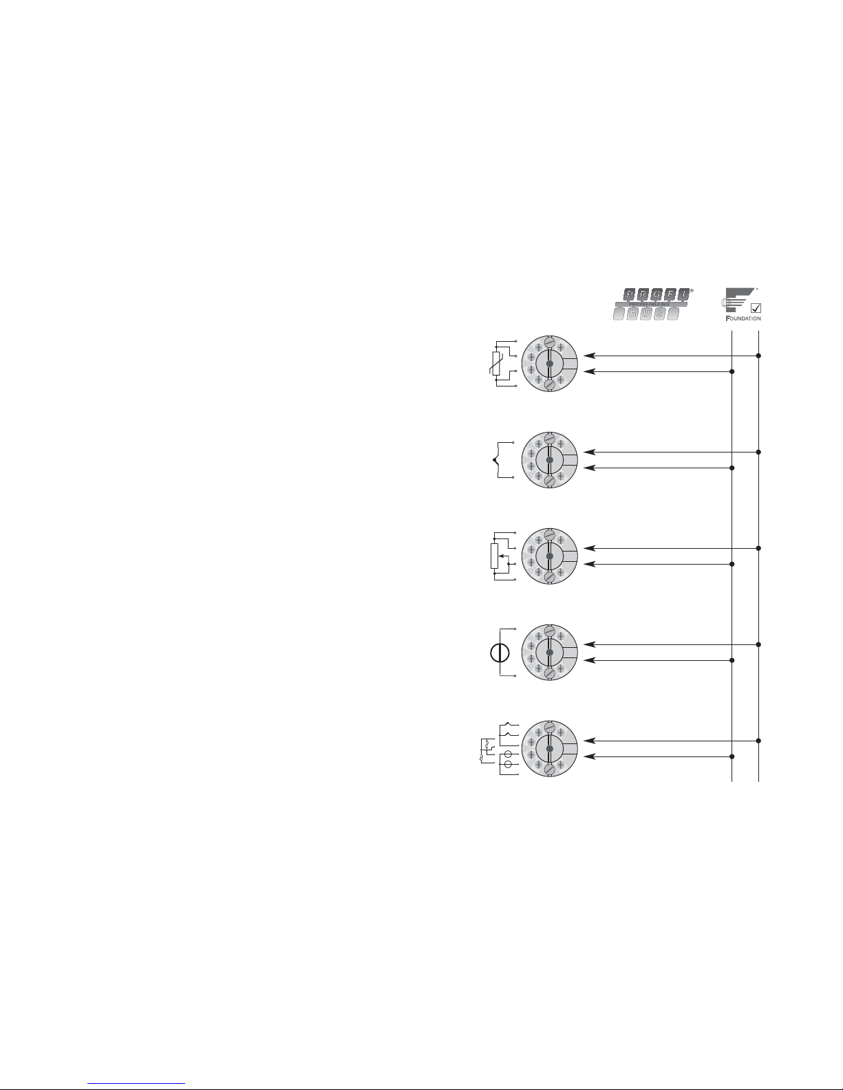
5
+
-
+
-
+
-
1
+
2
+
-
+
-
2
1
2
1
-
RTD til
bus-kommunikation
Modstand til
bus-kommunikation
mV til
bus-kommunikation
TC til
bus-kommunikation
Differens, redundans eller
middel; RTD, TC eller mV
eller
PROFIBUS® PA / FOUNDATION™ FIELDBUS
TRANSMITTER - PRetop 5350
• PROFIBUS® PA ver. 3.0
• FOUNDATION™ Fieldbus ver. ITK 4.6
• Automatisk switchfunktion
• FISCO-certificeret
• Basic funktionalitet med F.F.
Anvendelse:
• Temperaturlineariseret måling med RTD- eller termoelementføler.
• Differens-, redundans- eller gennemsnitstemperaturmåling med RTD- eller termoelementføler.
• Lineær modstand, potentiometer og bipolær mV-måling.
Teknisk karakteristik:
• Bustransmitter med både PROFIBUS® PA og FOUNDATION™ Fieldbus kommu-
nikation. En unik switchfunktion sørger for automatisk skift mellem protokollerne.
• Opsætning til PROFIBUS
®
PA kan ske via Siemens Simatic® PDM®, ABB
Melody / Harmony og Metso DNA XD software og til F
OUNDATION™ Fieldbus
via Emerson DeltaV, Yokogawa CS 1000 / CS 3000, ABB Melody / Harmony
og Honeywell Experion software.
• Simulation mode-funktion kan aktiveres via magnet.
• Polaritetsuafhængig busforsyning.
• 24 bit A/D konverter sikrer høj opløsning.
• PROFIBUS
®
PA funktionsblokke: 2 analoge.
• F
OUNDATION™ Fieldbus funktionsblokke: 2 analoge og 1 PID.
• F
OUNDATION™ Fieldbus funktionalitet: Basic eller LAS.
Montage / installation:
• Kan monteres i DIN form B følerhoved. I ikke-eksplosionsfarlige områder kan
5350 monteres på en DIN-skinne med PR-beslag type 8421.
4
Page 5
Vibration (DIN class B) ................................ IEC 60068-2-6 og IEC 60068-2-64
4 g / 2...100 Hz
Luftfugtighed ............................................... < 95% RH (ikke kond.)
Mål ............................................................... Ø 44 x 20,2 mm
Kapslingsklasse (hus / klemme) .................. IP68 / IP00
Vægt ............................................................ 55 g
Elektriske specifikationer, indgang:
RTD- og lineær modstandsindgang:
Kabelmodstand pr. leder ............................. 50 Ω
Følerstrøm ................................................... Nom. 0,2 mA
Virkning af følerkabelmodstand
(3- / 4-leder) .. < 0,002 Ω / Ω
Følerfejlsdetektering .................................... Ja
Kortslutningsdetektering ............................. < 15 Ω
7
Basisværdier
Indgangstype
Basis-
nøjagtighed
Temperatur-
koefficient
Pt100 og Pt1000 ≤ ±0,1°C ≤ ±0,002°C / °C
Ni100 ≤ ±0,15°C ≤ ±0,002°C / °C
Cu10 ≤ ±1,3°C ≤ ±0,02°C / °C
Lin. R ≤ ±0,05 Ω≤ ±0,002 Ω
/ °C
Volt ≤ ±10 µV ≤ ±0,2 µV / °C
TC-type:
E, J, K, L, N, T, U
≤ ±0,5°C ≤ ±0,010°C / °C
TC-type:
B, R, S, W3, W5
≤ ±1°C ≤ ±0,025°C / °C
EMC-immunitetspåvirkning ............................ < ±0,1% af visning
Udvidet EMC-immunitet:
NAMUR NE 21, A kriterium, gniststøj ............ < ±1% af visning
RTD-
type
Min.
værdi
Max.
værdi Standard
Pt25...Pt1000
Ni25...Ni1000
Cu10...Cu1000
Lin. modstand
Potentiometer
-200°C
-60°C
-50°C
0 Ω
0 Ω
+850°C
+250°C
+200°C
10 kΩ
100 kΩ
IEC60751/JIS C 1604
DIN 43760
α = 0,00427
-
-
*NB! Husk at bestille PR sim pin type 8422, hvis
„simulation mode“-funktionen ønskes benyttet.
Elektriske specifikationer:
Specifikationsområde:
-40°C til +85°C
Fælles specifikationer:
Forsyningsspænding DC:
Standard ................................................. 9,0...32 V
ATEX, FM, UL og CSA ............................ 9,0...30 V
I FISCO-installationer .............................. 9...17,5 V
Egetforbrug ................................................. < 11 mA
Max. stigning i strømforbrug
i tilfælde af en fejl .................................... < 7 mA
Isolationsspænding, test ............................. 1,5 kVAC i 60 s
Isolationsspænding, drift ............................. 50 VRMS / 75 VDC
Opvarmningstid ........................................... 30 s
Signal- / støjforhold ..................................... Min. 60 dB
Reaktionstid (programmerbar) .................... 1...60 s
Opdateringstid............................................. < 400 ms
Eksekveringstid, analog indgang ................ < 50 ms
Signaldynamik, indgang .............................. 24 bit
Kalibreringstemperatur ................................ 20...28°C
Nøjagtighed, størst af generelle og basisværdier:
6
Generelle værdier
Indgangstype
Absolut
nøjagtighed
Temperatur-
koefficient
Alle ≤ ±0,05% af visning ≤ ±0,002% af visning / °C
Page 6

9
Ex-godkendelse - 5350A:
KEMA 03ATEX1011 X
Ex-data:
Terminal 1, 2 (Fieldbus-kredsløb):
II 3 G EEx nA [nL] II C T4...T6
U
i
................................................................. : 32 VDC
eller
II 3 G EEx nL II C T4...T6
U
i
................................................................. : 32 VDC
L
i
................................................................. : 1 µH
C
i
................................................................. : 2 nF
eller
FNICO feltmonteret udstyr
U
i
................................................................. : 17,5 VDC
med følgende kabelparametre:
R
c
................................................................ : 15...150 Ω/km
L
c
................................................................ : 0,4...1 mH/km
C
c
................................................................ : 45...200 nF/km
Længde af sidekabel max. 60 m i IIC og IIB.
Længde af hovedkabel inklusive længde af alle sidekabler max. 1 km i IIC og 5
km i IIB.
Terminal 3, 4, 5 og 6 (følerkredsløb):
U
o
................................................................ : 5,7 VDC
I
o
................................................................. : 8,4 mA
P
o
................................................................ : 12 mW
L
o
................................................................ : 200 mH
C
o
................................................................ : 40 µF
FM, UL og CSA ........................................... IS, Class I, Div. 2, Group A, B, C, D
IS, Class I, Zone 2, Group IIC
TC-indgang:
Koldt loddestedskomp. (CJC) ..................... < ±0,5 °C
Følerfejlsdetektering .................................... Ja
Følerfejlsstrøm:
under detektering .................................... Nom. 4 µA
ellers ........................................................ 0 µA
Kortslutningsdetektering ............................. < 3 mV
Spændingsindgang:
Måleområde ................................................ -800...+800 mV
Indgangsmodstand ..................................... 10 MΩ
Udgang:
PROFIBUS®PA tilslutning:
PROFIBUS®PA protokol .............................. Profil A&B, ver. 3.0
PROFIBUS®PA protokolstandard ................ EN 50170 vol. 2
PROFIBUS®PA adresse (ved levering) ........ 126
PROFIBUS®PA funktionsblokke .................. 2 analoge
FOUNDATIONTM Fieldbus tilslutning:
FOUNDATIONTM Fieldbus protokol ................. FF protokol
F
OUNDATION
TM
Fieldbus protokolstandard ... FF designspecifikationer
F
OUNDATION
TM
Fieldbus funktionalitet .......... LAS eller Basic
F
OUNDATION
TM
Fieldbus version ................... ITK 4.6
F
OUNDATION
TM
Fieldbus funktionsblokke ..... 2 analoge og 1 PID
8
Type
Min.
værdi
Max.
værdi Standard
B
E
J
K
L
N
R
S
T
U
W3
W5
Ekst. CJC
+400°C
-100°C
-100°C
-180°C
-200°C
-180°C
-50°C
-50°C
-200°C
-200°C
0°C
0°C
-40°C
+1820°C
+1000°C
+1200°C
+1372°C
+900°C
+1300°C
+1760°C
+1760°C
+400°C
+600°C
+2300°C
+2300°C
+135°C
IEC 60584-1
IEC 60584-1
IEC 60584-1
IEC 60584-1
DIN 43710
IEC 60584-1
IEC 60584-1
IEC 60584-1
IEC 60584-1
DIN 43710
ASTM E988-90
ASTM E988-90
IEC60751
Page 7
1110
EEx- / I.S.-godkendelse - 5350B:
KEMA 02ATEX1318 ..................................... II 1 GD el. II 2 (1) GD,
T65°C...T105°C
EEx ia IIC eller EEx ib [ia] IIC T4...T6
Må anvendes i zone .................................... 0, 1, 2, 20, 21 eller 22
FM, UL og CSA ........................................... IS, Class I, Div. 1, Group A, B, C, D
IS, Class I, Zone 0/1, Group IIC
IS, Class I, Div. 2, Group A, B, C, D
Ex- / I.S.-data:
Signaludgang / forsyning, terminal 1 til 2:
Max. omgivelsestemperatur er afhængig af den tilsluttede barrieres
P
o
.
Enhed
5350B
Zone 0, EEx ia IIC, Entity / Fisco
IS, Class I, Division 1, Group A, B, C, D
Entity / Fisco
Barriere med
Po < 0,84 W
Barriere med
Po < 1,3 W
Kan anvendes i
FISCO-systemer
Kan anvendes i
FISCO-systemer
U
i
I
i
P
i
L
i
C
i
T1...T4
T5
T6
30 VDC
120 mADC
0,84 W
1 µH
2,0 nF
T
omg.
< 85°C
T
omg.
< 70°C
T
omg.
< 60°C
30 VDC
300 mADC
1,3 W
1 µH
2,0 nF
T
omg.
< 75°C
T
omg.
< 65°C
T
omg.
< 45°C
17,5 VDC
250 mADC
2,0 W
1 µH
2,0 nF
T
omg.
< 85°C
T
omg.
< 60°C
T
omg.
< 45°C
15 VDC
900 mA
5,32 W
1 µH
2,0 nF
T
omg.
< 85°C
T
omg.
< 60°C
T
omg.
< 45°C
Enhed
5350B
Zone 1, EEx ib IIC, Entity / Fisco
IS, Class I, Division 2, Group A, B, C, D
Entity / Fisco
Barriere med
P
o
< 5,32 W
FISCO seg-
mentkobler
U
i
I
i
P
i
L
i
C
i
T1...T4
T5
T6
30 VDC
250 mADC
5,32 W
1 µH
2,0 nF
T
omg.
< 85°C
T
omg.
< 75°C
T
omg.
< 60°C
17,5 VDC
alle
alle
1 µH
2,0 nF
T
omg.
< 85°C
T
omg.
< 75°C
T
omg.
< 60°C
Følerindgang, terminal 3, 4, 5 og 6:
U
o
................................................................ : 5,7 VDC
I
o
................................................................. : 8,4 mA
P
o
................................................................ : 12 mW
L
o
................................................................ : 200 mH
C
o
................................................................ : 40 µF
GOST R godkendelse:
Standard: VNIIM .......................................... Cert. no. Ross DK.ME48.V01899
Ex: VNIIFTRI ................................................ Cert. no. Ross DK.GB06.V00100
Ex permit ..................................................... РРС00-17800
Overholdte myndighedskrav: Standard:
EMC 2004/108/EF
Emission og immunitet ....................... EN 61326-1 : 2006
ATEX 94/9/EF .............................................. EN 50014 : 1997, EN 50020 : 2002,
EN 60079-15 : 2003, EN 50284 : 1999
EN 60079-27 : 2005
FM ............................................................... 3600, 3610, 3611
UL ................................................................ UL 508, UL 1604, UL 913,
UL 60079-0, UL 60079-1
CSA, CAN / CSA ......................................... C22.2 No. 142, No. 157, No. 213,
CAN / CSA .................................................. E79-0, -11, -15
ANSI / UL .................................................... UL 60079-0, -11, -15
Page 8
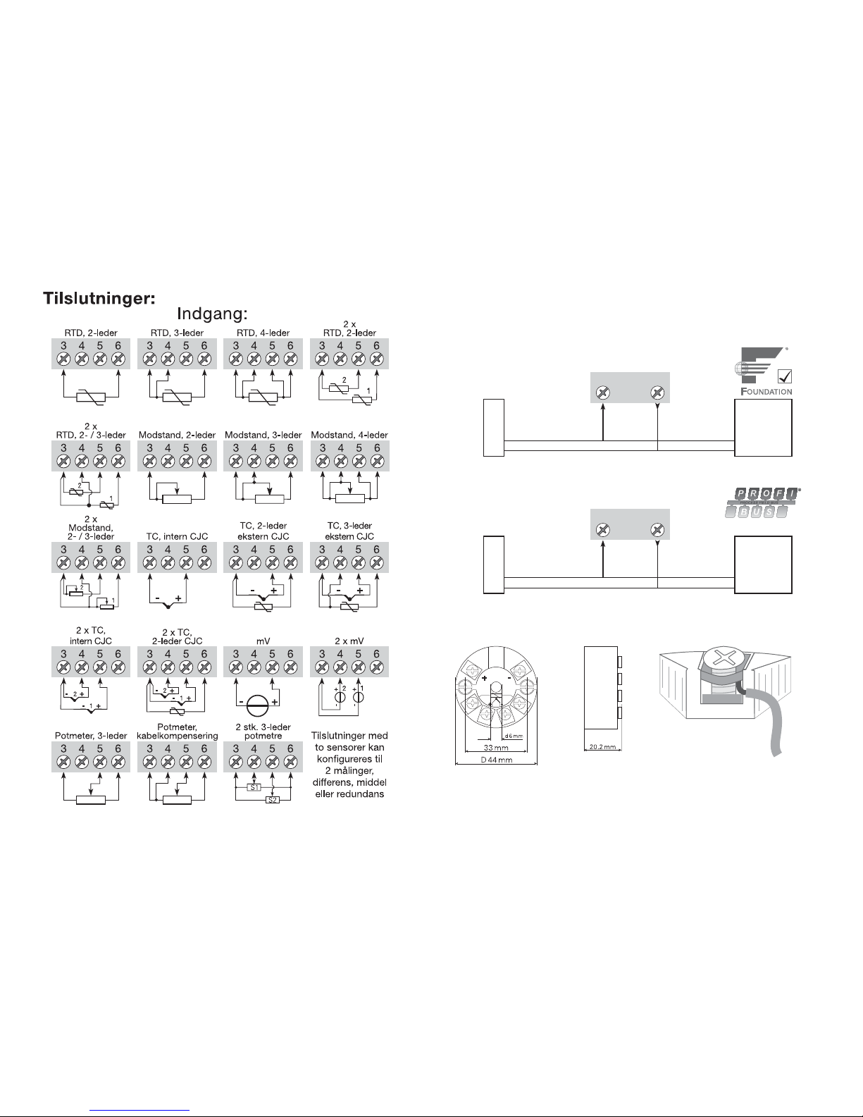
13
1 2
1 2
PA
Bus-tilslutning
Bus-tilslutning
Tilslutninger:
Udgang:
Segment-
kobler
Segment-
kobler
Bus-
terminering
Bus-
terminering
12
Ledninger monteres mellem metalpladerne
Mekaniske specifikationer: Montering af følerledninger:
Page 9
15
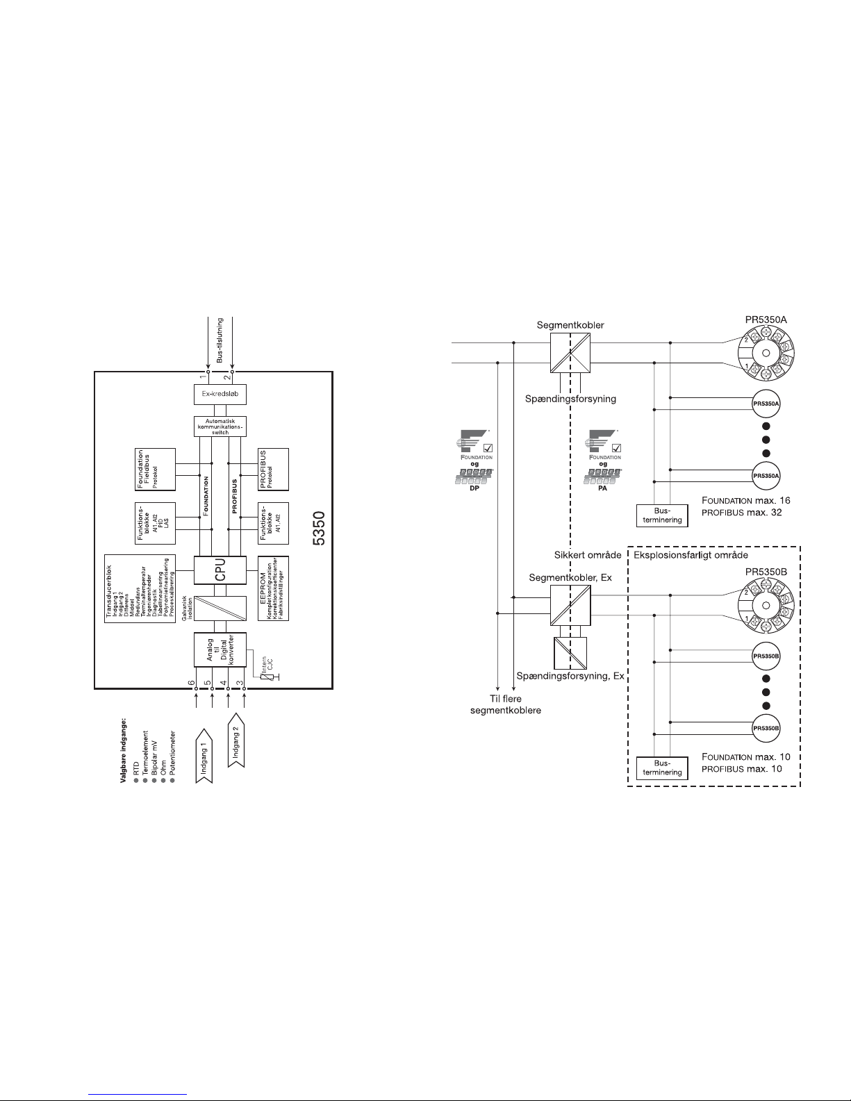
Blokdiagram:
14
Bus-installation:
Page 10

16 17
PROFIBUS® PA / FOUNDATION™ FIELDBUS
TRANSMITTER
PRetrans 5350
Contents
Safety instruction ............................................................... 18
EC Declaration of Conformity ............................................ 19
Application ......................................................................... 20
Technical characteristics .................................................... 20
Mounting / installation ........................................................ 20
Applications ........................................................................ 21
Order .................................................................................. 22
Electrical specifications ...................................................... 22
Connections, input ............................................................. 28
Connections, output ........................................................... 29
Mounting of sensor wires ................................................... 29
Block diagram .................................................................... 30
Bus installation ................................................................... 31
Appendix:
FM, UL, CSA and FISCO
Installation Drawing No. 5350QE01 ................................... 65
17
Page 11

18 1918
Safety instructions
Ex installation:
For safe installation of 5350 in a hazardous area, the following must be obser-
ved. The module must only be installed by qualified personnel who are familiar with the national and international laws, directives and standards that
apply to this area.
Year of manufacture can be taken from the first two digits in the serial number.
The sensor circuit is not infallibly galvanically isolated from the input circuit.
However, the galvanic isolation between the circuits is capable of withstan-
ding a test voltage of 500 Vac during 1 minute.
The transmitter must be mounted in an enclosure in order to provide a degree
of ingress protection of at least IP20.
In explosive atmospheres caused by air / dust mixtures:
The transmitter may only be installed in a potentially explosive atmosphere cau-
sed by the presence of combustible dust when mounted in a metal enclosu-
re form B according to DIN 43729 that is providing a degree of ingress pro-
tection of at least IP 6X in accordance with EN 60529, that is suitable for the
application and is correctly installed.
Cable entries and blanking elements shall be used that are suitable for the
application and correctly installed.
For an ambient temperature ≥60°C, heat resistant cables shall be used with a
rating of at least 20 K above the ambient temperature.
Special Conditions for Safe Use - 5350A:
The transmitter shall be mounted in an enclosure providing a degree of ingress
protection of at least IP54 in accordance with EN 60529.
Provisions must be made to prevent the rated supply voltage being exceeded
by transient disturbances of more than 40%.
Special Conditions for Safe Use - 5350B:
If the enclosure in which the transmitter is mounted is made of aluminium and
installed in Zone 0, 1 or Zone 20, 21 or 22 it shall not contain by weight more
than 6% in total of magnesium and titanium.
The additional enclosure of the apparatus shall be designed and/or installed in
such a way that, even in the event of rare incidents, ignition sources due to
impact and friction sparks are excluded.
EC DECLARATION OF CONFORMITY
As manufacturer
PR electronics A/S
Lerbakken 10
DK-8410 Rønde
hereby declares that the following product:
Type: 5350
Name: PROFIBUS
®
PA / FOUNDATION™
Fieldbus transmitter
is in conformity with the following directives and standards:
EMC directive 2004/108/EC and later amendments
EN 61326-1 : 2006
For specification of the acceptable EMC performance level, refer to the
electrical specifications for the module.
The ATEX directive 94/9/EC and later amendments
EN 50014 : 1997, EN 50020 : 2002,
EN 60079-15 : 2003, EN 50284 : 1999,
EN 60079-27 : 2005
ATEX certificate: KEMA 03ATEX1011 X (5350A)
ATEX certificate: KEMA 02ATEX1318 (5350B)
Notified body
KEMA Quality B.V. (0344)
Utrechtseweg 310, 6812 AR Arnhem
P.O. Box 5185, 6802 ED Arnhem
The Netherlands
Rønde, 13 May 2008 Peter Rasmussen
Manufacturer’s signature
19
Page 12
20 21
PROFIBUS® PA / FOUNDATION™ FIELDBUS
TRANSMITTER - PRetop 5350
• PROFIBUS® PA ver. 3.0
• FOUNDATION™ Fieldbus ver. ITK 4.6
• Automatic switch between protocols
• FISCO-certified
• Basic capability with F.F.
Application:
• Linearised temperature measurement with RTD or TC sensor.
• Difference, average or redundancy temperature measurement with RTD or TC
sensor.
• Linear resistance, potentiometer and bipolar mV measurement.
Technical characteristics:
• Bus transmitter with both PROFIBUS® PA and FOUNDATIONTMFieldbus
communication. A unique switch function ensures automatic shift between
the two protocols.
• Set-up for PROFIBUS
®
PA can be done via Siemens Simatic
®
PDM®, ABB
Melody / Harmony and Metso DNA software and for F
OUNDATION™ Fieldbus
via Emerson DeltaV, Yokogawa CS 1000 / CS 3000, ABB Melody / Harmony
and Honeywell Experion software.
• The simulation mode function can be activated by way of a magnet.
• Polarity-independent bus connection.
• 24 bit A/D converter ensures high resolution.
• PROFIBUS
®
PA function blocks: 2 analogue.
• F
OUNDATION™ Fieldbus function blocks: 2 analogue and 1 PID.
• F
OUNDATION™ Fieldbus capability: Basic or LAS.
Mounting / installation:
• For DIN form B sensor head mounting. In non-hazardous areas the 5350 can
be mounted on a DIN rail with the PR fitting type 8421.
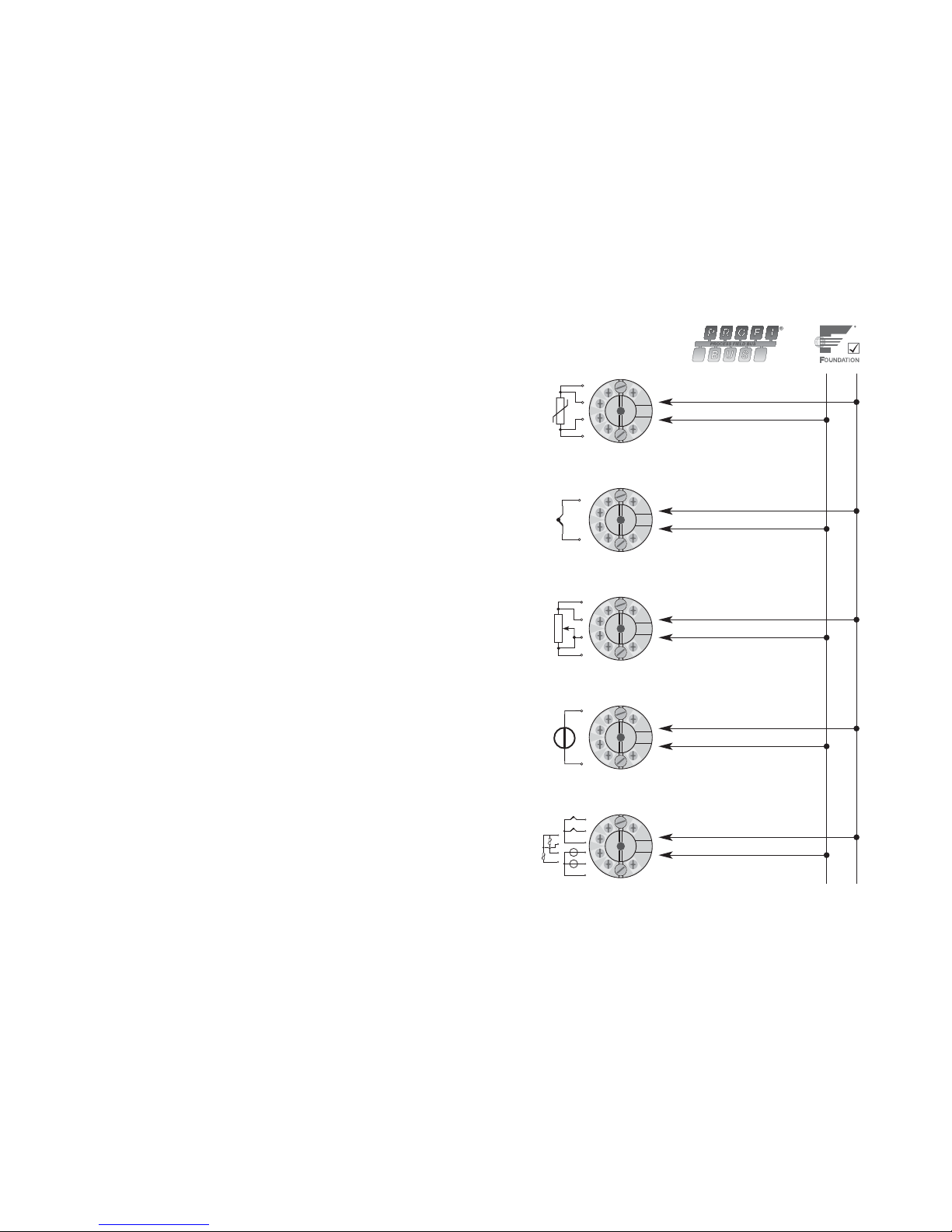
20 21
+
-
+
-
+
-
1
+
2
+
-
+
-
2
1
2
1
-
RTD to
bus communication
Resistance to
bus communication
mV to
bus communication
TC to
bus communication
Difference, redundancy or
average; RTD, TC or mV
or
Page 13
22 23
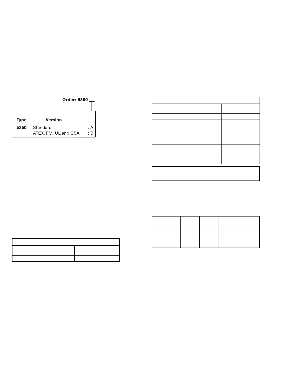
*NB! Please remember to order PR sim pin type 8422
if the simulation mode function is to be used.
Electrical specifications:
Specifications range:
-40°C to +85°C
Common specifications:
Supply voltage, DC
Standard ................................................. 9.0...32 V
ATEX, FM, UL and CSA .......................... 9.0...30 V
In FISCO installations ............................. 9.0...17.5 V
Consumption ............................................... < 11 mA
Max. current increase in
the event of an error ............................... < 7 mA
Isolation voltage, test .................................. 1.5 kVAC for 60 s
Isolation voltage, operation ......................... 50 VRMS / 75 VDC
Warm-up time .............................................. 30 s
Signal / noise ratio ...................................... Min. 60 dB
Response time (programmable) .................. 1...60 s
Updating time .............................................. < 400 ms
Execution time, analogue input ................... < 50 ms
Signal dynamics, input ................................ 24 bit
Calibration temperature .............................. 20...28°C
Accuracy, the greater of general and basic values:
22
General values
Input type
Absolute
accuracy
Temperature
coefficient
All ≤ ±0.05% of reading ≤ ±0.002% of reading / °C
Vibration (DIN class B) ................................ IEC 60068-2-6 and IEC 60068-2-64
4 g / 2...100 Hz
Humidity ...................................................... < 95% RH (non cond.)
Dimensions .................................................. Ø 44 x 20.2 mm
Protection degree (enclosure / terminal) ..... IP68 / IP00
Weight ......................................................... 55 g
Electrical specifications, input:
RTD and linear resistance input:
Cable resistance per wire ............................ 50 Ω
Sensor current ............................................. Nom. 0.2 mA
Effect of sensor cable resistance
(3- / 4-wire) < 0.002 Ω / Ω
Sensor error detection ................................ Yes
Short circuit detection ................................. < 15 Ω
23
Basic values
Input type
Basic
accuracy
Temperature
coefficient
Pt100 and Pt1000 ≤ ±0.1°C ≤ ±0.002°C / °C
Ni100 ≤ ±0.15°C ≤ ±0.002°C / °C
Cu10 ≤ ±1.3°C ≤ ±0.02°C / °C
Lin. R ≤ ±0.05 Ω≤ ±0.002 Ω
/ °C
Volt ≤ ±10 µV ≤ ±0.2 µV / °C
TC type:
E, J, K, L, N, T, U
≤ ±0.5°C ≤ ±0.010°C / °C
TC type:
B, R, S, W3, W5
≤ ±1°C ≤ ±0.025°C / °C
EMC immunity influence ................................ < ±0.1% of reading
Extended EMC immunity:
NAMUR NE 21, A criterion, burst .................. < ±1% of reading
RTD
type
Min.
value
Max.
value Standard
Pt25...Pt1000
Ni25...Ni1000
Cu10...Cu1000
Lin. resistance
Potentiometer
-200°C
-60°C
-50°C
0 Ω
0 Ω
+850°C
+250°C
+200°C
10 kΩ
100 kΩ
IEC60751/JIS C 1604
DIN 43760
α = 0.00427
-
-
Page 14

24 25
TC input:
Cold junction compensation (CJC) ............. < ±0.5 °C
Sensor error detection ................................ Yes
Sensor error current:
when detecting ....................................... Nom. 4 µA
else .......................................................... 0 µA
Short circuit detection ................................. < 3 mV
Voltage input:
Measurement range .................................... -800...+800 mV
Input resistance ........................................... 10 MΩ
Output:
PROFIBUS®PA connection:
PROFIBUS®PA protocol .............................. Profile A&B, ver. 3.0
PROFIBUS®PA protocol standard ............... EN 50170 vol. 2
PROFIBUS®PA address (at delivery) ........... 126
PROFIBUS®PA function blocks ................... 2 analogue
FOUNDATIONTM Fieldbus connection:
FOUNDATIONTM Fieldbus protocol ................. FF protocol
F
OUNDATION
TM
Fieldbus protocol standard .. FF design specifications
F
OUNDATION
TM
Fieldbus capability ............... Basic or LAS
F
OUNDATION
TM
Fieldbus version ................... ITK 4.6
F
OUNDATION
TM
Fieldbus function blocks ...... 2 analogue and 1 PID
24
Type
Min.
value
Max.
value Standard
B
E
J
K
L
N
R
S
T
U
W3
W5
Ext. CJC
+400°C
-100°C
-100°C
-180°C
-200°C
-180°C
-50°C
-50°C
-200°C
-200°C
0°C
0°C
-40°C
+1820°C
+1000°C
+1200°C
+1372°C
+900°C
+1300°C
+1760°C
+1760°C
+400°C
+600°C
+2300°C
+2300°C
+135°C
IEC584
IEC584
IEC584
IEC584
DIN 43710
IEC584
IEC584
IEC584
IEC584
DIN 43710
ASTM E988-90
ASTM E988-90
IEC6075
25
Ex approval - 5350A:
KEMA 03ATEX1011 X
Ex data:
Terminal 1, 2 (Fieldbus circuit):
II 3 G EEx nA [nL] II C T4...T6
U
i
................................................................. : 32 VDC
or
II 3 G EEx nL II C T4...T6
U
i
................................................................. : 32 VDC
L
i
................................................................. : 1 µH
C
i
................................................................. : 2 nF
or
FNICO field device
U
i
................................................................. : 17.5 VDC
with cable parameters:
R
c
................................................................ : 15...150 Ω/km
L
c
................................................................ : 0.4...1 mH/km
C
c
................................................................ : 45...200 nF/km
Spur cable length max. 60 m in IIC and IIB.
Trunk cable length inclusive length of all spurs max. 1 km in IIC and 5 km in IIB.
Terminal 3, 4, 5 and 6 (sensor circuit):
U
o
................................................................ : 5.7 VDC
I
o
................................................................. : 8.4 mA
P
o
................................................................ : 12 mW
L
o
................................................................ : 200 mH
C
o
................................................................ : 40 µF
FM, UL and CSA ......................................... IS, Class I, Div. 2, Group A, B, C, D
IS, Class I, Zone 2, Group IIC
Page 15
26 2726
EEx / I.S. approval - 5350B:
KEMA 02ATEX1318 ..................................... II 1 GD or II 2 (1) GD,
T65°C...T105°C
EEx ia IIC or EEx ib [ia] IIC T4...T6
Applicable in zone ....................................... 0, 1, 2, 20, 21 or 22
FM, UL and CSA ......................................... IS, Class I, Div. 1, Group A, B, C, D
IS, Class I, Zone 0/1, Group IIC
IS, Class I, Div. 2, Group A, B, C, D
Ex / I.S. data:
Signal output / supply, terminal 1 to 2:
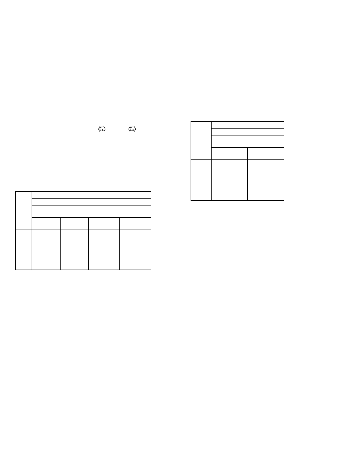
Max. ambient temperature depends on the
P
o
of the connected barrier.
Sensor input, terminal 3, 4, 5 and 6:
U
o
................................................................ : 5.7 VDC
I
o
................................................................. : 8.4 mA
P
o
................................................................ : 12 mW
L
o
................................................................ : 200 mH
C
o
................................................................ : 40 µF
GOST R approval:
Standard: VNIIM .......................................... Cert. no. Ross DK.ME48.V01899
Ex: VNIIFTRI ................................................ Cert. no. Ross DK.GB06.V00100
Ex permit ..................................................... РРС00-17800
Observed authority requirements: Standard:
EMC 2004/108/EC
Emission and immunity ....................... EN 61326-1 : 2006
ATEX 94/9/EC .............................................. EN 50014 : 1997, EN 50020 : 2002,
EN 60079-15 : 2003, EN 50284 : 1999,
EN 60079-27 : 2005
FM ............................................................... 3600, 3610, 3611
UL ................................................................ UL 508, UL 1604, UL 913,
UL 60079-0, UL 60079-1
CSA, CAN / CSA ......................................... C22.2 No. 142, No. 157, No. 213,
CAN / CSA .................................................. E79-0, -11, -15
ANSI / UL .................................................... UL 60079-0, -11, -15
Unit
5350B
Zone 0, EEx ia IIC, Entity / Fisco
IS, Class I, Division 1, Group A, B, C, D
Entity / Fisco
Barrier where
Po < 0.84 W
Barrier where
Po < 1.3 W
Suitable for
FISCO systems
Suitable for
FISCO systems
U
i
I
i
P
i
L
i
C
i
T1...T4
T5
T6
30 VDC
120 mADC
0.84 W
1 µH
2.0 nF
T
amb.
< 85°C
T
amb.
< 70°C
T
amb.
< 60°C
30 VDC
300 mADC
1.3 W
1 µH
2.0 nF
T
amb.
< 75°C
T
amb.
< 65°C
T
amb.
< 45°C
17.5 VDC
250 mADC
2,0 W
1 µH
2.0 nF
T
amb.
< 85°C
T
amb.
< 60°C
T
amb.
< 45°C
15 VDC
900 mA
5.32 W
1 µH
2.0 nF
T
amb.
< 85°C
T
amb.
< 60°C
T
amb.
< 45°C
Unit
5350B
Zone 1, EEx ib IIC, Entity / Fisco
IS, Class I, Division 2, Group A, B, C, D
Entity / Fisco
Barriere where
Po < 5.32 W
FISCO segment
coupler
U
i
I
i
P
i
L
i
C
i
T1...T4
T5
T6
30 VDC
250 mADC
5.32 W
1 µH
2.0 nF
T
amb.
< 85°C
T
amb.
< 75°C
T
amb.
< 60°C
17.5 VDC
All
All
1 µH
2.0 nF
T
amb.
< 85°C
T
amb.
< 75°C
T
amb.
< 60°C
Page 16
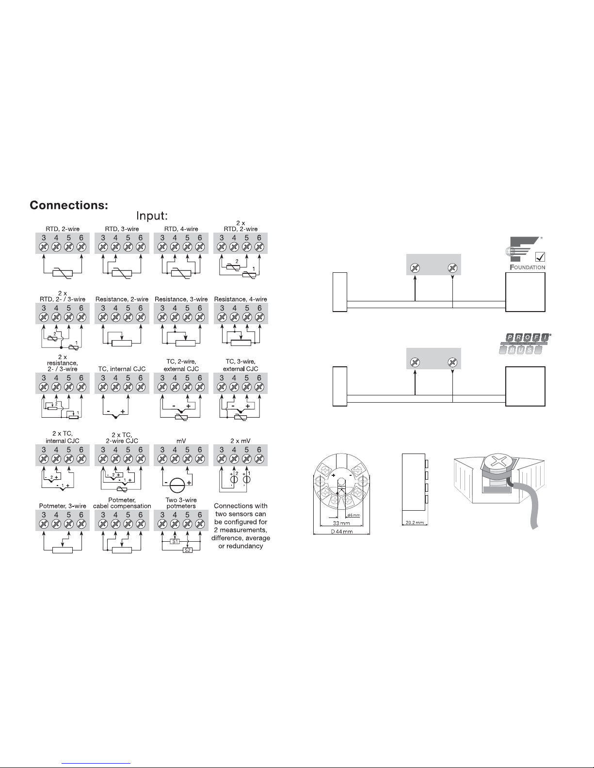
28 29
1 2
1 2
PA
Connections:
Output:
Bus connection
Bus connection
Segment
coupler
Segment
coupler
Bus
termination
Bus
termination
Wires must be mounted between the metal
plates.
Mechanical specifications: Mounting of sensor wires
Page 17
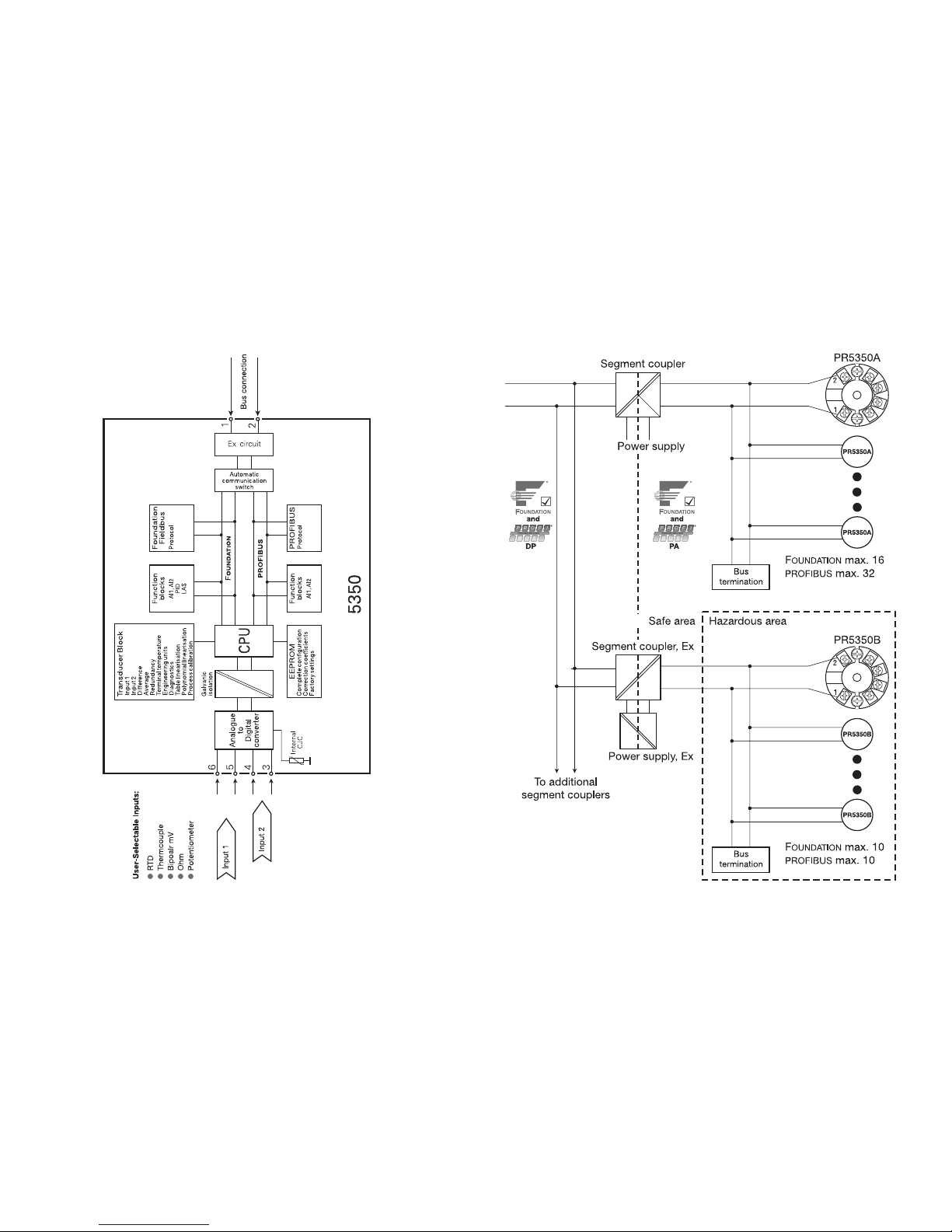
30 31
Block diagram: Bus installation:
Page 18

32 33
TRANSMETTEUR PROFIBUS® PA /
FIELDBUS FOUNDATION™
PRetrans 5350
Sommaire
Consigne de sécurité ......................................................... 34
Déclaration de conformité CE ............................................ 35
Application ......................................................................... 36
Caractéristiques techniques .............................................. 36
Montage / installation ......................................................... 36
Applications ........................................................................ 37
Référence ........................................................................... 38
Spécifications électriques .................................................. 38
Connexions, entrée ............................................................ 44
Connexions, sortie ............................................................. 45
Montage des fils du capteur .............................................. 45
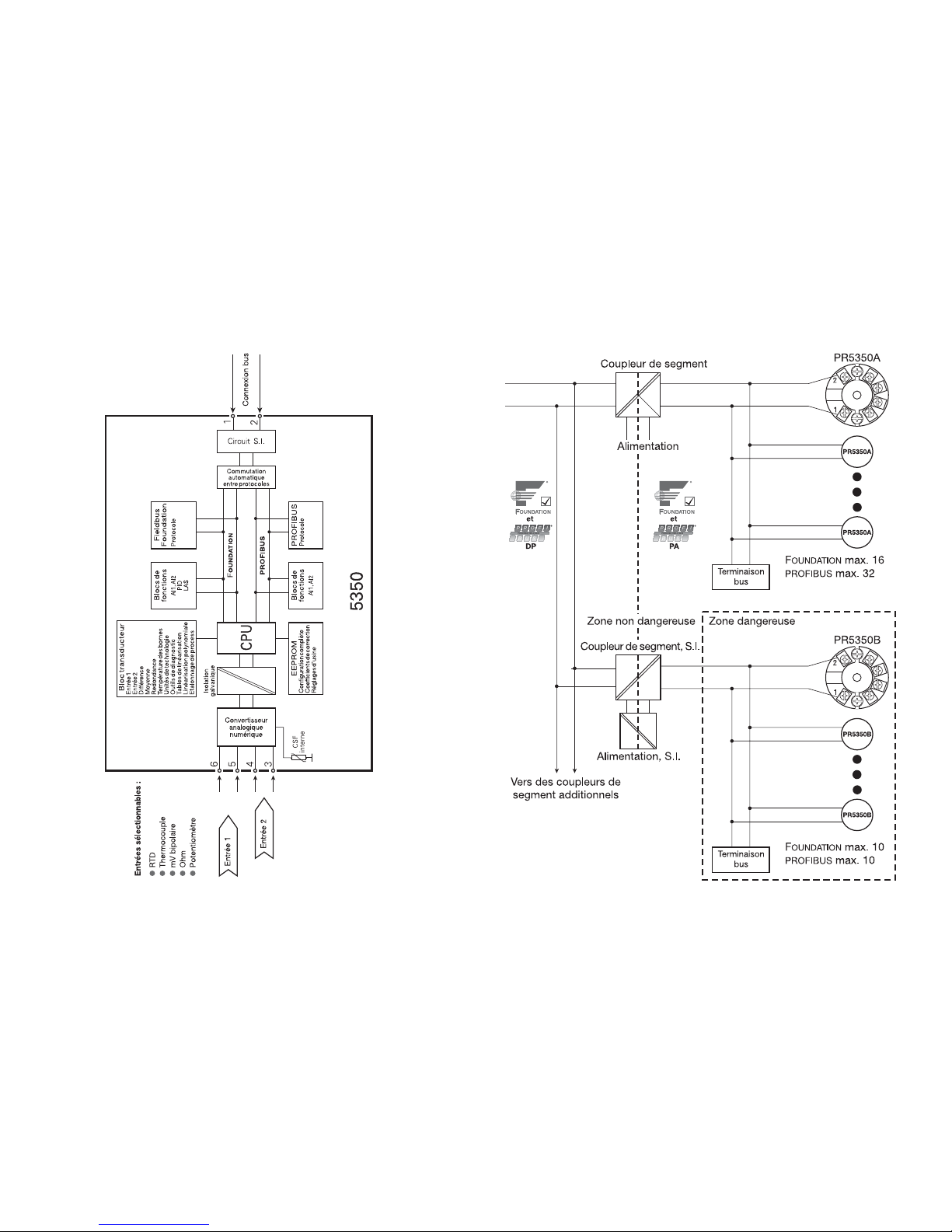
Schéma de principe ........................................................... 46
Installation bus ................................................................... 47
Appendix:
FM, UL, CSA and FISCO
Installation Drawing No. 5350QE01 ................................... 65
Page 19

34 35
Consigne de sécurité
Installation S.I. :
Pour l’installation de 5350 dans les zones dangereuses, conformez-vous aux
consignes de sécurité suivantes : l’installation ne doit être réalisée que par du
personnel qualifié connaissant la législation nationale et internationale ainsi
que les directives et standards régissant ce domaine.
L’année de production ressort des deux premiers chiffres du numéro de série.
L’isolation galvanique entre le circuit du capteur et le circuit d’entrée n’est pas
infaillible. Cependant, l’isolation galvanique entre les circuits est capable de
résister à une tension de test de 500 Vca pendant 1 minute.
Le transmetteur doit être monté dans un boîtier assurant un degré d’étanchéité
d’au moins IP20.
Dans les atmosphères explosibles dues à des mélanges d’air avec des poussières :
Le transmetteur doit seulement être installé dans les atmosphères potentiellement
explosibles dû à la présence de poussières combustibles quand il est monté
dans un boîtier métallique DIN B conformément à DIN 43729 assurant un
degré d’étanchéité d’au moins IP 6X conformément à l’EN 60529. Ce boîtier
doit convenir à l’application et il doit être correctement installé.
Seulement des raccords de câble et des bouchons convenant à l’application et
correctement installés doivent être utilisés.
Pour une température ambiante ≥60°C, il faut utiliser des câbles résistant aux
températures élevées avec une capacité nominale d’au moins 20 K au dessus
de la température ambiante.
Conditions spécifiques à l’utilisation sûre - 5350A :
Le transmetteur doit être installé dans un boîtier de protection assurant un
degré d’étanchéité d’au moins IP54 conformément à l’EN 60529.
Il faut prendre des mesures pour éviter que la tension d’alimentation nominelle
soit dépassée par des transitoires de plus de 40%.
Conditions spécifiques à l’utilisation sûre - 5350B :
Si le boîtier dans lequel est monté le transmetteur est fait d’aluminium et installé
en zone 0, 1 ou zone 20, 21 ou 22, il ne doit contenir en poids plus que 6%
en total de magnésium et de titane.
Le boîtier supplémentaire de l’apparail doit être construit et/ou installé dans
une telle manière que, même dans le cas d’incidents rares, les sources
d’inflammation dûes aux impacts et aux étincelles de friction ne peuvent se
produire.
DECLARATION DE CONFORMITE CE
En tant que fabricant
PR electronics A/S
Lerbakken 10
DK-8410 Rønde
déclare que le produit suivant :
Type: 5350
Nom: Transmetteur PROFIBUS
®
PA / Fieldbus
FOUNDATION™
correspond aux directives et normes suivantes :
La directive CEM (EMC) 2004/108/CE et les modifications subséquentes
EN 61326-1 : 2006
Pour une spécification du niveau de rendement acceptable CEM (EMC),
renvoyer aux spécifications électriques du module.
La directive ATEX 94/9/CE et les modifications subséquentes
EN 50014 : 1997, EN 50020 : 2002,
EN 60079-15 : 2003, EN 50284 : 1999,
EN 60079-27 : 2005
Certificat ATEX : KEMA 03ATEX1011 X (5350A)
Certificat ATEX : KEMA 02ATEX1318 (5350B)
Organisme notifié :
KEMA Quality B.V. (0344)
Utrechtseweg 310, 6812 AR Arnhem
P.O. Box 5185, 6802 ED Arnhem
The Netherlands
Rønde, le 13 mai 2008 Peter Rasmussen
Signature du fabricant
35
Page 20
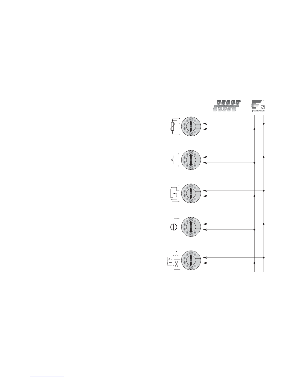
36 37
TRANSMETTEUR PROFIBUS® PA / FIELDBUS
FOUNDATION™ - PRetop 5350
• PROFIBUS® PA ver. 3.0
• Fieldbus FOUNDATION™ ver. ITK 4.6
• Commutation automatique entre protocoles
• Certifié aux normes FISCO
• Basic en Fieldbus Foundation™
Application :
• Mesure linéarisée de la température avec sonde résistive ou thermocouple.
• Mesure de la température différentielle, moyenne ou redondance avec sonde
résistive ou thermocouple.
• Résistance linéaire, potentiomètre et mesure de tension bipolaire (mV).
Caractéristiques techniques :
• Transmetteur de bus avec communication PROFIBUS® PA et Fieldbus FOUN-
DATION
TM
. Une fonction de commutation unique assure le passage d’un pro-
tocole à l’autre de manière automatique.
• Configuration PROFIBUS
®
PA avec les logiciels Siemens Simatic® PDM®, ABB
Melody / Harmony et Metso DNA et Fieldbus F
OUNDATION™ avec les logiciels
Emerson DeltaV, Yokogawa CS 1000 / CS 3000, ABB Melody / Harmony et
Honeywell Experion.
• Le mode de simulation peut être activé à l’aide d’un aimant.
• La connexion du bus est indépendante de la polarité.
• Le convertisseur A/D de 24 bit assure une très haute résolution du signal.
• Blocs de fonctions PROFIBUS
®
PA : 2 blocs analogiques.
• Blocs de fonctions Fieldbus F
OUNDATION™ : 2 blocs analogiques et 1 bloc PID.
• Fonctionnalités en Fieldbus F
OUNDATION™ : Basic. ou LAS.
Montage / installation :
• Pour tête de sonde DIN B. En zone non-dangereuse le 5350 peut être monté
sur rail DIN avec le support PR type 8421.
36 37
+
-
+
-
+
-
1
+
2
+
-
+
-
2
1
2
1
-
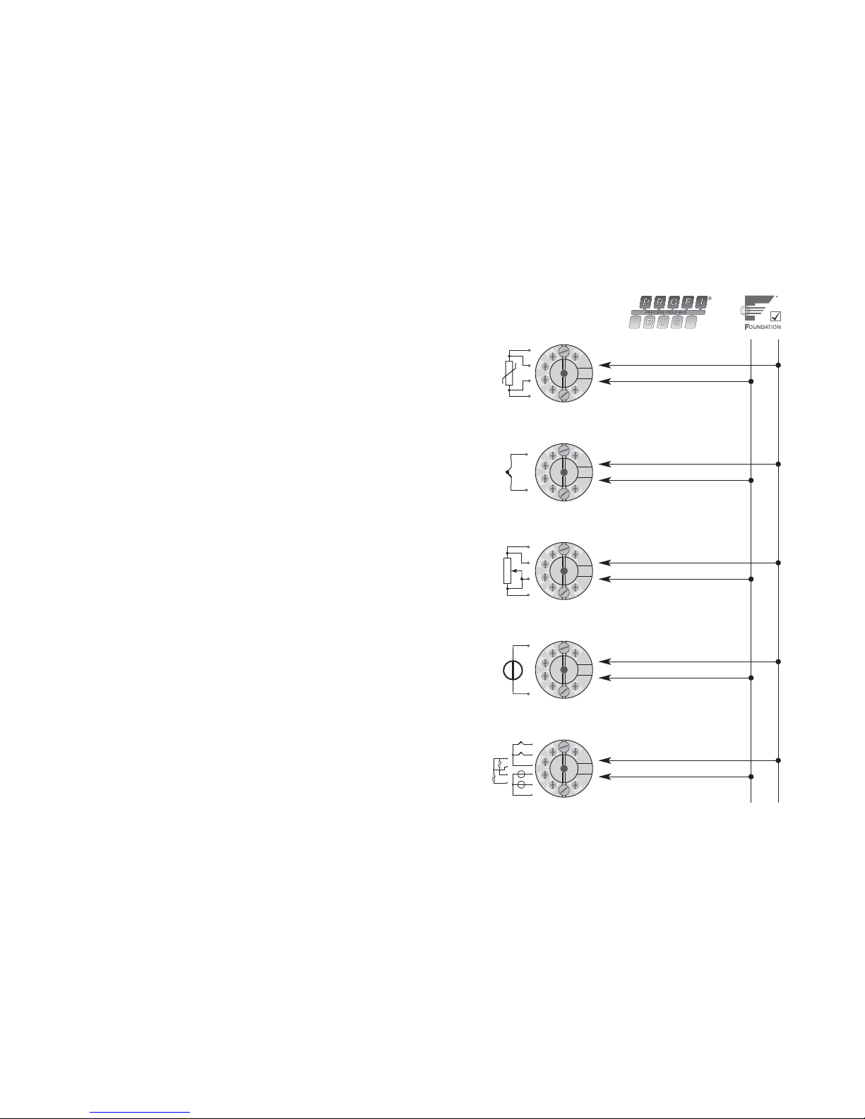
RTD en
communication de bus
Résistance en
communication de bus
mV en
communication de bus
TC en
communication de bus
Différence, redondance ou
moyenne; RTD, TC ou mV
ou
Page 21
38 39
*N.B. ! Si le mode de simulation doit être activé,
rappellez-vous de commander le PR sim pin type 8422.
Spécifications électriques :
Plage des spécifications :
-40°C à +85°C
Spécifications communes :
Tension d’alimentation, cc
Standard ................................................. 9,0...32 V
ATEX, FM, UL et CSA ............................. 9,0...30 V
Dans les installations FISCO .................. 9,0...17,5 V
Consommation ............................................ < 11 mA
Augmentation max. de la consommation
lors d’une erreur ...................................... < 7 mA
Tension d’isolation, test ............................... 1,5 kVca pendant 60 s
Tension d’isolation, opération ..................... 50 VRMS / 75 Vcc
Temps de chauffe ........................................ 30 s
Rapport signal / bruit .................................. Min. 60 dB
Temps de réponse (programmable) ............ 1...60 s
Temps de scrutation .................................... < 400 ms
Temps d’exécution, entrée analogique ....... < 50 ms
Dynamique du signal d’entrée .................... 24 bit
Température d’étalonnage .......................... 20...28°C
Précision, la plus grande des valeurs générales et de base :
38
Valeurs générales
Type
d’entrée
Précision
absolue
Coefficient
de température
Tous ≤ ±0,05% de la valeur ≤ ±0,002% de la valeur / °C
Vibration (DIN class B) ................................ IEC 60068-2-6 et IEC 60068-2-64
4 g / 2...100 Hz
Humidité ...................................................... < 95% RH (sans cond.)
Dimensions .................................................. Ø 44 x 20,2 mm
Degré de protection (boîtier / bornier) ........ IP68 / IP00
Poids ........................................................... 55 g
Spécifications électriques, entrée :
Entrée résistance linéaire et RTD :
Résistance de ligne par fil ........................... 50 Ω
Courant de sonde ....................................... Nom. 0,2 mA
Effet de la résistance de ligne (3- / 4-fils) ... < 0,002 Ω / Ω
Détection de rupture sonde ........................ Oui
Détection de court-circuit ........................... < 15 Ω
39
Valeurs de base
Type
d’entrée
Précision
de base
Coefficient
de température
Pt100 et Pt1000 ≤ ±0,1°C ≤ ±0,002°C / °C
Ni100 ≤ ±0,15°C ≤ ±0,002°C / °C
Cu10 ≤ ±1,3°C ≤ ±0,02°C / °C
R. lin. ≤ ±0,05 Ω≤ ±0,002 Ω
/ °C
Volt ≤ ±10 µV ≤ ±0,2 µV / °C
Type TC :
E, J, K, L, N, T, U
≤ ±0,5°C ≤ ±0,010°C / °C
Type TC :
B, R, S, W3, W5
≤ ±1°C ≤ ±0,025°C / °C
Immunité CEM ................................................ < ±0,1% d. la valeur
Immunité CEM améliorée :
NAMUR NE 21, critère A, burst ..................... < ±1% de la valeur
Type
RTD
Valeur
min.
Valeur
max. Standard
Pt25...Pt1000
Ni25...Ni1000
Cu10...Cu1000
Résistance lin.
Potentiomètre
-200°C
-60°C
-50°C
0 Ω
0 Ω
+850°C
+250°C
+200°C
10 kΩ
100 kΩ
IEC60751/JIS C 1604
DIN 43760
α = 0,00427
-
-
Page 22

40 41
Entrée TC :
Compensation de soudure froide (CSF) ..... < ±0,5 °C
Détection de rupture sonde ........................ Oui
Courant de sonde:
pendant la détection ............................... Nom. 4 µA
si non ...................................................... 0 µA
Détection de court-circuit ........................... < 3 mV
Entrée tension :
Gamme de mesure ...................................... -800...+800 mV
Résistance d’entrée .................................... 10 MΩ
Sortie :
Connexion PROFIBUS®PA :
Protocole PROFIBUS®PA ............................. Profile A&B, ver. 3.0
Standard protocole
PROFIBUS®PA ............ EN 50170 vol. 2
Adresse
PROFIBUS®PA (à la livraison) ....... 126
Blocs de fonctions
PROFIBUS®PA ............. 2 bloc analogiques
Connexion Fieldbus FOUNDATIONTM :
Protocole Fieldbus FOUNDATIONTM ............... Protocole FF
Std protocole Fieldbus F
OUNDATION
TM
........ Spécifications au design FF
Fonctionnalités Fieldbus F
OUNDATION
TM
...... Basic ou LAS
Version Fieldbus F
OUNDATION
TM
.................. ITK 4.6
Blocs de fonctions Fieldbus F
OUNDATION
TM
.. 2 blocs analogiques et 1 bloc PID
40
Type
Valeur
min.
Valeur
max. Standard
B
E
J
K
L
N
R
S
T
U
W3
W5
CSF ext.
+400°C
-100°C
-100°C
-180°C
-200°C
-180°C
-50°C
-50°C
-200°C
-200°C
0°C
0°C
-40°C
+1820°C
+1000°C
+1200°C
+1372°C
+900°C
+1300°C
+1760°C
+1760°C
+400°C
+600°C
+2300°C
+2300°C
+135°C
IEC584
IEC584
IEC584
IEC584
DIN 43710
IEC584
IEC584
IEC584
IEC584
DIN 43710
ASTM E988-90
ASTM E988-90
IEC60751
41
Approbation S.I. - 5350A :
KEMA 03ATEX1011 X
Caractéristiques S.I. :
Borne 1, 2 (Circuit Fieldbus) :
II 3 G EEx nA [nL] II C T4...T6
U
i
................................................................. : 32 Vcc
ou
II 3 G EEx nL II C T4...T6
U
i
................................................................. : 32 Vcc
L
i
................................................................. : 1 µH
C
i
................................................................. : 2 nF
ou
FNICO unité monté en zone
U
i
................................................................. : 17,5 Vcc
avec les caractéristiques de câble suivants :
R
c
................................................................ : 15...150 Ω/km
L
c
................................................................ : 0,4...1 mH/km
C
c
................................................................ : 45...200 nF/km
Longueur maximale du câble secondaire = 60 m en IIC et IIB.
Longueur maximale du câble primaire y inclus la longueur de tous les câbles
secondaires = 1 km en IIC et 5 km en IIB.
Borne 3, 4, 5 et 6 (circuit capteur) :
U
o
................................................................ : 5,7 Vcc
I
o
................................................................. : 8,4 mA
P
o
................................................................ : 12 mW
L
o
................................................................ : 200 mH
C
o
................................................................ : 40 µF
FM, UL et CSA ............................................ IS, Class I, Div. 2, Group A, B, C, D
IS, Class I, Zone 2, Group IIC
Page 23
42 4342
Approbation EEx / S.I. - 5350B :
KEMA 02ATEX1318 ..................................... II 1 GD ou II 2 (1) GD,
T65°C...T105°C
EEx ia IIC ou EEx ib [ia] IIC T4...T6
Applicable en zone ...................................... 0, 1, 2, 20, 21 ou 22
FM, UL et CSA ............................................ IS, Class I, Div. 1, Group A, B, C, D
IS, Class I, Zone 0/1, Group IIC
IS, Class I, Div. 2, Group A, B, C, D
Caractéristiques S.I. :
Sortie de signal / alimentation, borne 1 à 2 :
La température ambiante max. dépend de la valeur Po de la barrière connectée.
Entrée capteur, borne 3, 4, 5 et 6:
Uo ................................................................ : 5,7 Vcc
I
o
................................................................. : 8,4 mA
P
o
................................................................ : 12 mW
L
o
................................................................ : 200 mH
C
o
................................................................ : 40 µF
Approbation GOST R :
Standard : VNIIM ......................................... Cert. no. Ross DK.ME48.V01899
S.I. : VNIIFTRI .............................................. Cert. no. Ross DK.GB06.V00100
Ex permit ..................................................... РРС00-17800
Agréments et homologations : Standard :
CEM (EMC) 2004/108/CE
Emission et immunité ....................... EN 61326-1 : 2006
ATEX 94/9/CE .............................................. EN 50014 : 1997, EN 50020 : 2002,
EN 60079-15 : 2003, EN 50284 : 1999,
EN 60079-27 : 2005
FM ............................................................... 3600, 3610, 3611
UL ................................................................ UL 508, UL 1604, UL 913,
UL 60079-0, UL 60079-1
CSA, CAN / CSA ......................................... C22.2 No. 142, No. 157, No. 213,
CAN / CSA .................................................. E79-0, -11, -15
ANSI / UL .................................................... UL 60079-0, -11, -15
Unité
5350B
Zone 0, EEx ia IIC, Entity / Fisco
IS, Class I, Division 1, Group A, B, C, D
Entity / Fisco
Barrière où
Po < 0,84 W
Barrière où
Po < 1,3 W
Peut être utilisé en
systèmes FISCO
Peut être utilisé en
systèmes FISCO
U
i
I
i
P
i
L
i
C
i
T1...T4
T5
T6
30 Vcc
120 mAcc
0,84 W
1 µH
2,0 nF
T
amb.
< 85°C
T
amb.
< 70°C
T
amb.
< 60°C
30 Vcc
300 mAcc
1,3 W
1 µH
2,0 nF
T
amb.
< 75°C
T
amb.
< 65°C
T
amb.
< 45°C
17,5 Vcc
250 mAcc
2,0 W
1 µH
2,0 nF
T
amb.
< 85°C
T
amb.
< 60°C
T
amb.
< 45°C
15 Vcc
900 mA
5,32 W
1 µH
2,0 nF
T
amb.
< 85°C
T
amb.
< 60°C
T
amb.
< 45°C
Unité
5350B
Zone 1, EEx ib IIC, Entity / Fisco
IS, Class I, Division 2, Group A, B, C, D
Entity / Fisco
Barrière où
P
o
< 5,32 W
Coupleur de
segment FISCO
U
i
I
i
P
i
L
i
C
i
T1...T4
T5
T6
30 Vcc
250 mAcc
5,32 W
1 µH
2,0 nF
T
amb.
< 85°C
T
amb.
< 75°C
T
amb.
< 60°C
17,5 Vcc
Toutes
Toutes
1 µH
2,0 nF
T
amb.
< 85°C
T
amb.
< 75°C
T
amb.
< 60°C
Page 24

44 45
1 2
1 2
PA
Connexions :
Sortie :
Connexion bus
Connexion bus
Coupleur de
segment
Coupleur de
segment
Terminaison
bus
Terminaison
bus
Dimensions mécaniques : Montage des fils du capteur
Les fils doivent être montés entre les
plaques métalliques.
Page 25
46 47
Schema de principe : Installation bus :
Page 26

48 49
PROFIBUS® PA / FOUNDATION™ FIELDBUS
MESSUMFORMER
PRetrans 5350
Inhaltsverzeichnis
Sicherheitsanweisung ........................................................ 50
EG-Konformitätserklärung.................................................. 51
Verwendung ........................................................................ 52
Technische Merkmale ......................................................... 52
Montage / Installation ......................................................... 52
Anwendungen .................................................................... 53
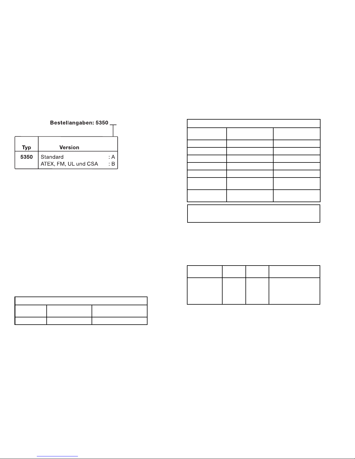
Bestellangaben ................................................................... 54
Elektrische Daten ............................................................... 54
Anschlüsse, Eingang .......................................................... 60
Anschlüsse, Ausgang ......................................................... 61
Montage von Fühlerleitungen ............................................. 61
Blockdiagramm .................................................................. 62
Businstallation .................................................................... 63
Appendix:
FM, UL, CSA and FISCO
Installation Drawing No. 5350QE01 ................................... 65
Page 27

50 51
Sicherheitsanweisung
Ex-Installation:
Für sichere Installation von 5350 in explosionsgefährdeter Umgebung muss fol-
gendes beobachtet werden. Die Installation muss nur von qualifizierten Personen, die mit den nationalen und internationalen Gesetze, Direktiven und
Standards des Gebiets bekannt sind, vorgenommen werden.
Die ersten beiden Ziffern der Seriennummer geben das Produktionsjahr an.
Die galvnische Trennung zwischen dem Sensorkreis und dem Eingangskreis ist
nicht unfehlbar. Allerdings ist die galvanische Trennung zwischen den Kreisen
so ausgelegt, dass diese eine Testspannung von 500 Vac für eine Minute
aushält.
Der Messumformer muss in einem Gehäuse montiert werden, um die Mindes t-
anforderung des Berührungsschutzes mit dem Schutzgrad IP 20 zu erreichen.
In Explosionsfähige Atmosphären durch Staub/Luft-Gemische:
Der Messumformer darf nur in einer potentiellen explosiven Atmosphäre,
basierend auf entflammbaren Staub, eingesetzt werden, wenn er in einem
Metallkopf Form B gemäß DIN 43729 montiert ist, welcher einen Schutzgrad
von mindestens IP 6X gemäß EN 60529 besitzt und für den dementsprechen-
den Einsatz zugelassen ist.
Es dürfen nur Kabeleinführungen und Abdeckungen eingesetzt werden, welche
für die jeweilige Anwendung zugelassen sind.
Bei einer Umgebungstemperatur ≥60°C müssen hitzebeständige Leitungen
eingesetzt werden, welche für eine mindestens 20 K höhere Umgebungstem-
peratur zugelassen sind.
Sonderbedingungen für sichere Anwendung - 5350A:
Der Messumformer 5350A muss in einem Gehäuse entsprechend dem Berüh-
rungsschutz der Schutzklasse IP 54 gemäß EN 60529 eingebaut werden.
Bei transienten Störungen über 40% der Nennspeisespannung müssen spezielle
Vorkehrungen zum Schutz des Gerätes getroffen werden.
Sonderbedingungen für sichere Anwendung - 5350B:
Wenn der Messumformer in einem Gehäuse montiert wird, welches in Zone 0, 1
oder Zone 20, 21 oder 22 installiert ist, darf das Gehäuse maximal 6% Mag-
nesium und Titanium einhalten. Hier müssen die allgemein geltenden Regeln
der Technik eingehalten werden.
Das zusätzliche Gehäuse ist so zu wählen und zu montieren, dass Zündquellen
(Stöße und Reibungsfunken) selbst bei selten auftretenden Störungen vermie-
den werden.
EG-KONFORMITÄTSERKLÄRUNG
Als Hersteller bescheinigt
PR electronics A/S
Lerbakken 10
DK-8410 Rønde
hiermit für das folgende Produkt:
Typ: 5350
Name: PROFIBUS
®
PA / FOUNDATION™ Fieldbus
Messumformer
die Konformität mit folgenden Richtlinien und Normen:
Die EMV Richtlinien 2004/108/EG und nachfolgende Änderungen
EN 61326-1 : 2006
Zur Spezifikation des zulässigen Erfüllungsgrades, siehe die Elektrische Daten
des Moduls.
Die ATEX Richtlinien 94/9/EG und nachfolgende Änderungen
EN 50014 : 1997, EN 50020 : 2002,
EN 60079-15 : 2003, EN 50284 : 1999,
EN 60079-27 : 2005
ATEX-Zertifikat: KEMA 03ATEX1011 X (5350A)
ATEX-Zertifikat: KEMA 02ATEX1318 (5350B)
Zulassungsstelle:
KEMA Quality B.V. (0344)
Utrechtseweg 310, 6812 AR Arnhem
P.O. Box 5185, 6802 ED Arnhem
The Netherlands
Rønde, 13. Mai 2008 Peter Rasmussen
Unterschrift des Herstellers
51
Page 28
52 53
PROFIBUS® PA / FOUNDATION™ FIELDBUS
MESSUMFORMER - PRetop 5350
• PROFIBUS® PA Version 3.0
• FOUNDATION™ Fieldbus Version ITK 4.6
• Automatische Protokoll-Umschaltung
• FISCO-zertifiziert
• F.F. mit Basic-Funktionalität
Anwendungen:
• Linearisierte Temperaturmessungen mit Widerstandsthermometer oder Ther-
moelement.
• Differenz-, Mittelwert- oder redundante Temperaturmessungen mit Wider-
standsthermometer oder Thermoelement.
• Lineare Widerstands-, Kompensator- und bipolare mV-Messungen.
Technische Merkmale:
• Bus-Messumformer mit PROFIBUS® PA und FOUNDATION™ Fieldbus-
Kommunikation. Die einzigartige Umschaltfunktion ermöglicht eine automati-
sche Umschaltung zwischen den beiden Protokollen.
• Konfiguration über PROFIBUS
®
PA mit Siemens Simatic® PDM®, ABB Melody /
Harmony und Metso DNA Software und über F
OUNDATION™ Fieldbus mit
Emerson DeltaV, Yokogawa CS 1000 / CS 3000, ABB Melody / Harmony und
Honeywell Experion Software.
• Der Simulationsmodus kann mittels eines Magneten aktiviert werden.
• Polaritätsunabhängige Busanschluss.
• Der 24 Bit A/D-Wandler garantiert eine hohe Auflösung.
• PROFIBUS
®
PA Funktionsblöcke: 2 Analoge.
• F
OUNDATION™ Fieldbus Funktionsblöcke: 2 Analoge und 1 PID.
• F
OUNDATION™ Fieldbus Funktionalität: Basic oder LAS.
Montage / Installation:
• Für DIN Form B Sensorkopf Montage. Im sicheren Bereich kann der 5350 auf
einer DIN- Schiene mittels der PR-Armatur Typ 8421 montiert werden.
52 53
+
-
+
-
+
-
1
+
2
+
-
+
-
2
1
2
1
-
WTH in
Bus-Kommunikation
Widerstand in
Bus-Kommunikation
mV in
Bus-Kommunikation
TE in
Bus-Kommunikation
Differenz, Redundanz oder
Mittel; WTH, TE oder mV
oder
Page 29
54 55
*Zu beachten! Wenn der Simulationsmodus aktiviert
werden soll, ist der PR Sim Pin Typ 8422 zu bestellen.
Elektrische Daten:
Spezifikationsbereich:
-40°C bis +85°C
Allgemeine Daten:
Versorgungsspannung, DC
Standard ................................................. 9,0...32 V
ATEX, FM, UL und CSA .......................... 9,0...30 V
In FISCO-Installationen ........................... 9,0...17,5 V
Stromverbrauch ........................................... < 11 mA
Max. Steigerung des Stromverbrauchs
im Falle einer Fehler ................................ < 7 mA
Isolationsspannung, Test ............................. 1,5 kVAC für 60 s
Isolationsspannung, Betrieb ........................ 50 VRMS / 75 VDC
Aufwärmzeit................................................. 30 s
Signal-Störabstand ..................................... Min. 60 dB
Ansprechzeit (programmierbar) ................... 1...60 s
Aktualisierungszeit ...................................... < 400 ms
Ausführungszeit, analoger Eingang ............ < 50 ms
Signaldynamik, Eingang .............................. 24 Bit
Kalibrierungstemperatur .............................. 20...28°C
Genauigkeit, höherer Wert von allgemeinen und Grundwerten:
54
Allgemeine Werte
Eingangsart
Absolute
Genauigkeit
Temperatur-
koeffizient
Alle ≤ ±0,05% v. Messw. ≤ ±0,002% v. Messw. / °C
Schwingungen (DIN class B) ....................... IEC 60068-2-6 und IEC 60068-2-64
4 g / 2...100 Hz
Feuchtigkeit ................................................. < 95% RF (nicht kond.)
Abmessungen ............................................. Ø 44 x 20,2 mm
Schutzart (Gehäuse / Klemmen) ................. IP68 / IP00
Gewicht ....................................................... 55 g
Elektrische Daten, Eingang:
WTH- und linearer Widerstandseingang:
Leitungswiderstand pro Leiter .................... 50 Ω
Fühlerstrom ................................................. Nom. 0,2 mA
Wirkung des Fühlerkabelwiderst.
(3-/4-Leiter) < 0,002 Ω / Ω
Fühlerfehlererkennung ................................. Ja
Kurzschlusserkennung ................................ < 15 Ω
55
Grundwerte
Eingangsart
Grund-
Genauigkeit
Temperatur-
koeffizient
Pt100 und Pt1000 ≤ ±0,1°C ≤ ±0,002°C / °C
Ni100 ≤ ±0,15°C ≤ ±0,002°C / °C
Cu10 ≤ ±1,3°C ≤ ±0,02°C / °C
Lin. R ≤ ±0,05 Ω≤ ±0,002 Ω
/ °C
Volt ≤ ±10 µV ≤ ±0,2 µV / °C
TC-Typ:
E, J, K, L, N, T, U
≤ ±0,5°C ≤ ±0,010°C / °C
TC-Typ:
B, R, S, W3, W5
≤ ±1°C ≤ ±0,025°C / °C
EMV Störspannungseinfluss .......................... < ±0,1% v. Messw.
Erweiterte EMV-Störfestigkeit:
NAMUR NE 21, Kriterium A, Burst ................. < ±1% v. Messw.
WTH-
Ty p
Min.
Wert
Max.
Wert Norm
Pt25...Pt1000
Ni25...Ni1000
Cu10...Cu1000
Linearer Widerst.
Potentiometer
-200°C
-60°C
-50°C
0 Ω
0 Ω
+850°C
+250°C
+200°C
10 kΩ
100 kΩ
IEC60751/JIS C 1604
DIN 43760
α = 0,00427
-
-
Page 30

56 57
TE-Eingang:
Vergleichstellungskompensation (CJC) ....... < ±0,5 °C
Fühlerfehlererkennung ................................. Ja
Fühlerfehlerstrom:
Bei Erkennung ......................................... Nom. 4 µA
Sonst ....................................................... 0 µA
Kurzschlusserkennung ................................ < 3 mV
Spannungseingang:
Messbereich ................................................ -800...+800 mV
Eingangswiderstand .................................... 10 MΩ
Ausgang:
PROFIBUS®PA-Verbindung:
PROFIBUS®PA Protokoll ............................. Profil A&B, Ver. 3.0
PROFIBUS®PA Protokollnorm ..................... EN 50170 Vol. 2
PROFIBUS®PA Adresse (bei Lieferung) ....... 126
PROFIBUS®PA Funktionsblöcke ................. 2 Analoge
FOUNDATIONTM Fieldbus-Verbindung:
FOUNDATIONTM Fieldbus Protokoll ................ FF Protokoll
F
OUNDATION
TM
Fieldbus Protokollnorm ........ FF Auslegungsbestimmungen
F
OUNDATION
TM
Fieldbus Funktionalität ......... Basic oder LAS
F
OUNDATION
TM
Fieldbus Version ................... ITK 4.6
F
OUNDATION
TM
Fieldbus Funktionsblöcke .... 2 Analoge and 1 PID
56
Ty p
Min.
Wert
Max.
Wert Norm
B
E
J
K
L
N
R
S
T
U
W3
W5
Ext. CJC
+400°C
-100°C
-100°C
-180°C
-200°C
-180°C
-50°C
-50°C
-200°C
-200°C
0°C
0°C
-40°C
+1820°C
+1000°C
+1200°C
+1372°C
+900°C
+1300°C
+1760°C
+1760°C
+400°C
+600°C
+2300°C
+2300°C
+135°C
IEC584
IEC584
IEC584
IEC584
DIN 43710
IEC584
IEC584
IEC584
IEC584
DIN 43710
ASTM E988-90
ASTM E988-90
IEC60751
57
Ex- / I.S.-Zulassung - 5350A:
KEMA 03ATEX1011 X
Ex-Daten:
Klemme 1, 2 (Fieldbus-Kreislauf):
II 3 G EEx nA [nL] II C T4...T6
U
i
................................................................. : 32 VDC
oder
II 3 G EEx nL II C T4...T6
U
i
................................................................. : 32 VDC
L
i
................................................................. : 1 µH
C
i
................................................................. : 2 nF
oder
FNICO Feld-Gerät
U
i
................................................................. : 17,5 VDC
mit den folgenden Leitungsdaten:
R
c
................................................................ : 15...150 Ω/km
L
c
................................................................ : 0,4...1 mH/km
C
c
................................................................ : 45...200 nF/km
Max. Länge der Abzweigleitung = 60 m in IIC und IIB.
Max. Länge der Verbindungsleitung inkl. alle Anzweigleitungen = 1 km in IIC
und 5 km in IIB.
Klemme 3, 4, 5 und 6 (Fühler-Kreislauf):
U
o
................................................................ : 5,7 VDC
I
o
................................................................. : 8,4 mA
P
o
................................................................ : 12 mW
L
o
................................................................ : 200 mH
C
o
................................................................ : 40 µF
FM, UL und CSA ......................................... IS, Class I, Div. 2, Group A, B, C, D
IS, Class I, Zone 2, Group IIC
Page 31
58 5958
EEx- / I.S.-Zulassung - 5350B:
KEMA 02ATEX1318 ..................................... II 1 GD od. II 2 (1) GD,
T65°C...T105°C
EEx ia IIC od. EEx ib [ia] IIC T4...T6
Anwendung in Zone .................................... 0, 1, 2, 20, 21 oder 22
FM, UL und CSA ......................................... IS, Class I, Div. 1, Group A, B, C, D
IS, Class I, Zone 0/1, Group IIC
IS, Class I, Div. 2, Group A, B, C, D
Ex- / I.S.-Daten:
Signalausgang / Versorgung, Klemme 1 bis 2:
Max. Umgebungstemperatur in Abhängigkeit von P
o
des angeschlossenen Ex-
Trenners.
Einheit
5350B
Zone 0, EEx ia IIC, Entity / Fisco
IS, Class I, Division 1, Group A, B, C, D
Entity / Fisco
Barriere mit
Po < 0,84 W
Barriere mit
Po < 1,3 W
Anwendung in
FISCO-Systeme
Anwendung in
FISCO-Systeme
U
i
I
i
P
i
L
i
C
i
T1...T4
T5
T6
30 VDC
120 mADC
0,84 W
1 µH
2,0 nF
T
Umg.
< 85°C
T
Umg.
< 70°C
T
Umg.
< 60°C
30 VDC
300 mADC
1,3 W
1 µH
2,0 nF
T
Umg.
< 75°C
T
Umg.
< 65°C
T
Umg.
< 45°C
17,5 VDC
250 mADC
2,0 W
1 µH
2,0 nF
T
Umg.
< 85°C
T
Umg.
< 60°C
T
Umg.
< 45°C
15 VDC
900 mA
5,32 W
1 µH
2,0 nF
T
Umg.
< 85°C
T
Umg.
< 60°C
T
Umg.
< 45°C
Fühlereingang, Klemme 3, 4, 5 und 6:
U
o
................................................................ : 5,7 VDC
I
o
................................................................. : 8,4 mA
P
o
................................................................ : 12 mW
L
o
................................................................ : 200 mH
C
o
................................................................ : 40 µF
GOST R Zulassung:
Standard: VNIIM .......................................... Cert. no. Ross DK.ME48.V01899
Ex: VNIIFTRI ................................................ Cert. no. Ross DK.GB06.V00100
Ex permit ..................................................... РРС00-17800
Eingehaltene Richtlinien: Norm:
EMV 2004/108/EG
Abstrahlung und Störfestigkeit .......... EN 61326-1 : 2006
ATEX 94/9/EG .............................................. EN 50014 : 1997, EN 50020 : 2002,
EN 60079-15 : 2003, EN 50284 : 1999,
EN 60079-27 : 2005
FM ............................................................... 3600, 3610, 3611
UL ................................................................ UL 508, UL 1604, UL 913,
UL 60079-0, UL 60079-1
CSA, CAN / CSA ......................................... C22.2 No. 142, No. 157, No. 213,
CAN / CSA .................................................. E79-0, -11, -15
ANSI / UL .................................................... UL 60079-0, -11, -15
Einheit
5350B
Zone 1, EEx ib IIC, Entity / Fisco
IS, Class I, Division 2, Group A, B, C, D
Entity / Fisco
Barriere mit
P
o
< 5,32 W
FISCO Segmentkoppler
U
i
I
i
P
i
L
i
C
i
T1...T4
T5
T6
30 VDC
250 mADC
5,32 W
1 µH
2,0 nF
T
Umg.
< 85°C
T
Umg.
< 75°C
T
Umg.
< 60°C
17,5 VDC
Alle
Alle
1 µH
2,0 nF
T
Umg.
< 85°C
T
Umg.
< 75°C
T
Umg.
< 60°C
Page 32
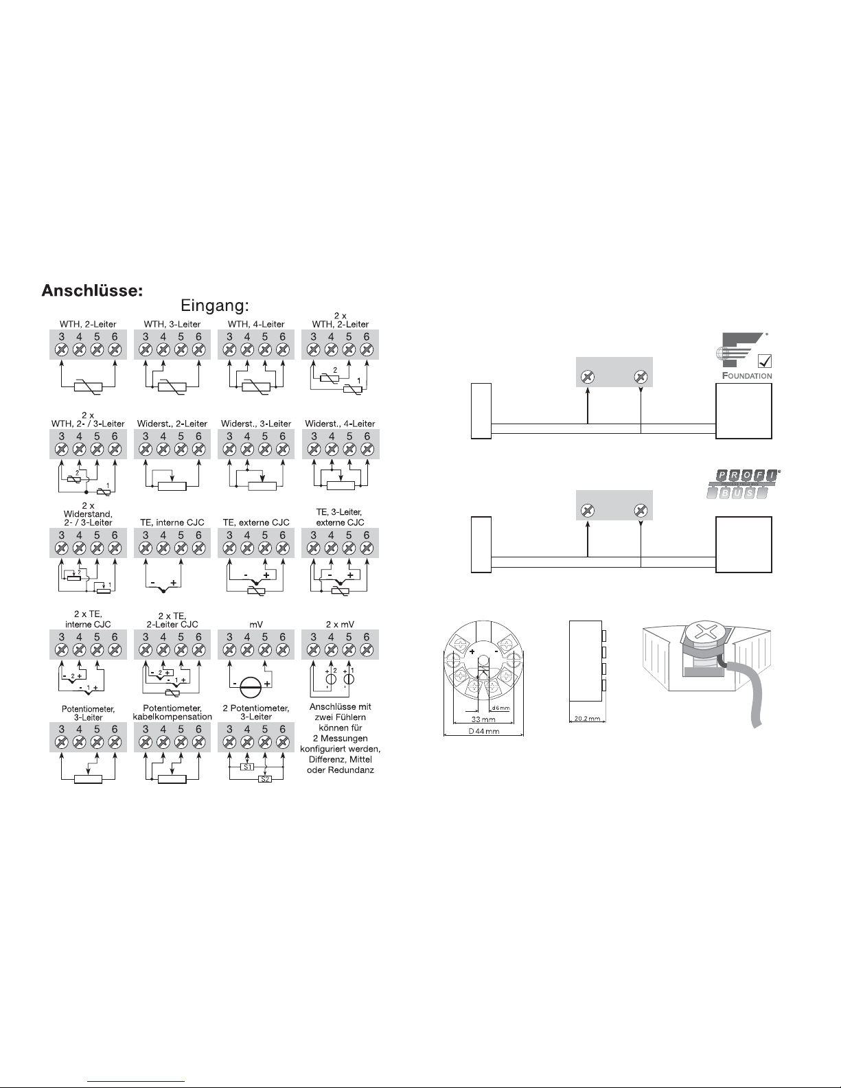
60 61
1 2
1 2
PA
A
nschlüsse:
Ausgang:
Bus-Verbindung
Bus-Verbindung
Segment-
koppler
Segment-
koppler
Bus-
Abschluss
Bus-
Abschluss
Abmessungen: Montage von Fühlerleitungen:
Die Leitungen müssen zwischen den
Metallplatten montiert werden.
Page 33
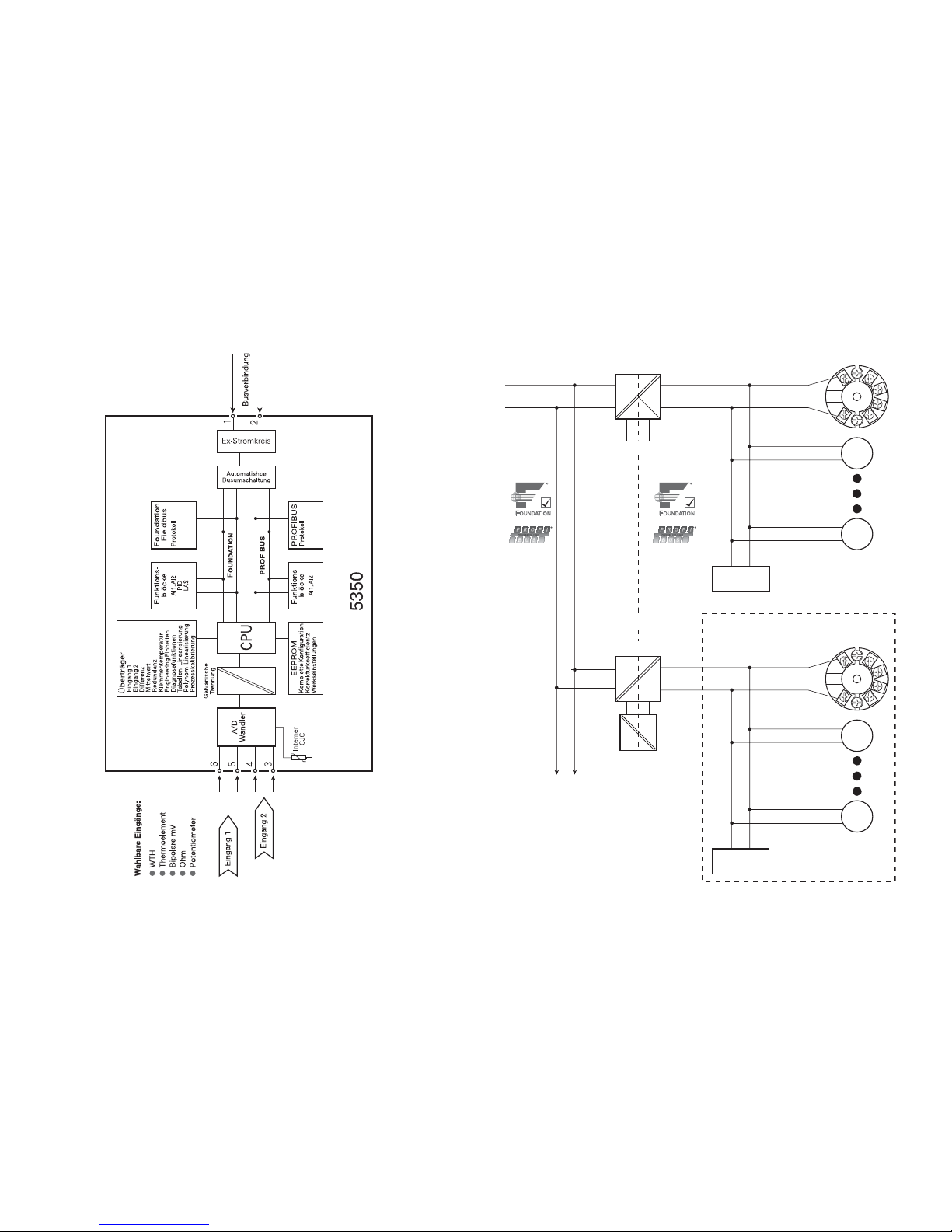
62 63
Blockdiagramm: Businstallation:
PR5350A
PR5350B
1
2
1
2
PR5350A
PR5350A
PR5350B
PR5350B
DP PA
Versorgung
Versorgung, Ex
Bus-
Abschluss
Segmentkoppler
F
OUNDATION max. 10
PROFIBUS max. 32
Segmentkoppler, Ex
Ex-gefährdeter BereichSicheres Bereich
An zusätzliche
Segmentkopplern
PROFIBUS max. 10
F
OUNDATION max. 16
Bus-
Abschluss
und und
Page 34

64 65
APPENDIX
FM, UL, CSA and FISCO
Installation Drawing No.
5350QE01
Page 35
66 67
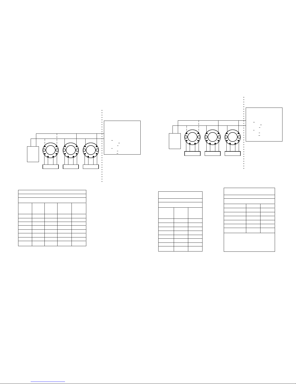
5350QE01.doc 2005-03-16 Rev. AC 1/7
Installation Drawing 5350QE01.
See Installation notes.
Terminal 1,2
Class I, Zone 0, Ex ia IIC, Entity / FISCO
IS, Class I, Division 1, Group A, B, C, D
Entity / FISCO
Barrier
type:
Linear
barrier
Trapezoid
barrier
Suitable for
FISCO
systems
Suitable for
FISCO
systems
T1..T4:
Ta +85CTa +75CTa +85CTa +85C
T5:
Ta +70CTa +65CTa +60CTa +60C
T6:
Ta +60CTa +45CTa +45CTa +45C
Vmax or Ui 30 V 30 V 17.5 V 15 V
Imax or Ii 120 mA 300 mA 250 mA 900 mA
Pi 0.84 W 1.3 W 2.0 W 5.32W
Ci 2.0 nF 2.0 nF 2.0 nF 2.0 nF
Li
1H1H1H1H
Unclassified Location
Hazardous (Classified) Location
Class I, Division1, Groups, A,B,C,D
OR
Class I, Zone 0, IIC
Associated Apparatus
Barrier or
FISCO Supply
with
entity Parameters:
Approved
Termination
SENSOR
5350B
1
2
3
45
6
SENSOR
5350B
1
2
3
45
6
SENSOR
5350B
1
2
3
45
6
Terminal 3, 4, 5, 6
Vt or Uo : 5.71 V
It or Io : 8.4 mA
Pt or Po : 12 mW
or Co : 40 uF
La or Lo : 200 mH
UM <
250V
Voc or Uo < Vmax or Ui
Isc or Io < Imax or Ii
Po < Pi
Ca or Co > Ci + Ccable
La or Lo > Li + Lcable
This device must not be
connected to any
associated apparatus
which uses or generates
more than 250 VRMS
Ca
5350QE01.doc 2005-03-16 Rev. AC 2/7
Unclassified Location
Hazardous (Classified) Location
Class I, Division2, Groups, A,B,C,D
OR
Class I, Zone 1, IIC
Associated Apparatus
Barrier with
entity Parameters:
Approved
Termination
SENSOR
5350B
1
2
3
45
6
SENSOR
5350B
1
2
3
45
6
SENSOR
5350B
1
2
3
45
6
Terminal 3, 4, 5, 6
Vt or Uo : 5.71 V
It or Io : 8.4 mA
Pt or Po : 12 mW
Ca or Co : 40 uF
La or Lo : 200 mH
UM < 250V
Voc or Uo < Vmax or Ui
Isc or Io < Imax or Ii
Po < Pi
Ca or Co > Ci + Ccable
La or Lo > Li + Lcable
or
FISCO Supply
This device must not be
connected to any
associated apparatus
which uses or generates
more than 250 VRMS
Nonincendive Field Wiring
parameters
Terminal 1, 2
NI, Class I, Division 2, Group A, B, C, D
NIFW/ FNICO
T1..T4:
Ta +85CTa +85C
T5:
Ta +75CTa +75C
T6:
Ta +60CTa +60C
Vmax / Ui 30 V 17.5 V
Pi 5.32 W any
Ci 2.0 nF 2.0 nF
Li
1H1H
For a current-controlled circuit the
parameter Imax is not required and
need not be aligned with the parameter
Isc or It of the barrier or associated
nonincendive field wiring apparatus.
Entity
Parameters
Terminal 1, 2
Class I, Zone 1, Ex ib IIC
Entity / FISCO
Barrier type: Rectangular
barrier
FISCO
Segment
coupler
T1..T4:
Ta +85CTa +85C
T5:
Ta +75CTa +75C
T6:
Ta +60CTa +60C
Vmax / Ui 30 V 17.5 V
Imax or Ii 250 mA any
Pi 5.32 W any
Ci 2.0 nF 2.0 nF
Li
1H1H
See Installation notes.
Page 36
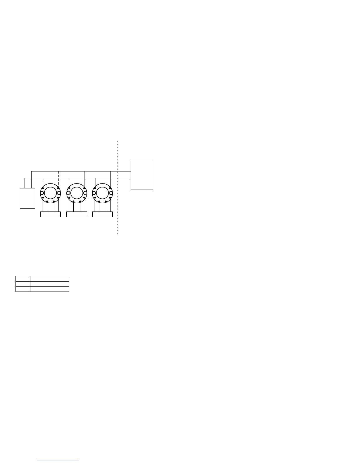
68 69
5350QE01.doc 2005-03-16 Rev. AC 3/7
SENSOR
32V
Class 2
Power Supply
Unclassified LocationHazardous (Classified) Location
5350A
1
2
3
45
6
Class I, Division2, Groups, A,B,C,D
OR
Class I, Zone 2, IIC
SENSOR
Approved
Termination
SENSOR
5350A 5350A
This device must not be
connected to any
associated apparatus
which uses or generates
more than 250 VRMS
Terminal 3, 4, 5, 6
Vt or Uo : 5.71 V
It or Io : 8.4 mA
Pt or Po : 12 mW
Ca or Co : 40 F
La or Lo : 200 mH
Terminal 1.2
Ci: 2.0 nF
Li: 1H
T1..T4
-40C Ta +85C
T5
-40C Ta +75C
T6
-40C Ta +60C
See installation notes:
5350QE01.doc 2005-03-16 Rev. AC 4/7
Installation notes:
FM / UL / CSA:
For installation in the US the 5350 shall be installed according to the National Electrical
Code (ANSI-NFPA 70).
For installation in Canada the transmitter shall be installed in a suitable enclosure to meet
installation codes stipulated in the Canadian Electrical Code (CEC).
The entity concept:
Equipment that is FM / UL / CSA-approved for intrinsic safety may be connected to barriers
based on the ENTITY CONCEPT. This concept permits interconnection of approved
transmitters, meters and other devices in combinations which have not been specifically
examined by FM / UL / CSA, provided that the agency's criteria are met. The combination is
intrinsically safe, if the entity concept is acceptable to the authority having jurisdiction over
the installation.
The entity concept criteria are as follows:
The intrinsically safe devices, other than barriers, must not be a source of power.
The maximum voltage Ui (V
MAX
) and current Ii (I
MAX
), and maximum power Pi (Pmax), which
the device can receive and remain intrinsically safe, must be equal to or greater than the
voltage (Uo or V
OC
or Vt) and current (Io or ISC or It) and the power Po which can be delivered
by the barrier.
The sum of the maximum unprotected capacitance (C
i
) for each intrinsically device and the
interconnecting wiring must be less than the capacitance (C
a
) which can be safely
connected to the barrier.
The sum of the maximum unprotected inductance (L
i
) for each intrinsically device and the
interconnecting wiring must be less than the inductance (L
a
) which can be safely connected
to the barrier.
The entity parameters Uo,V
OC
or Vt and Io,ISC or It, and Ca and La for barriers are provided by
the barrier manufacturer.
FISCO/FNICO rules:
The FISCO Concept allows the interconnection of intrinsically safe apparatus to associated
apparatus not specifically examined in such combination. The criterion for such
interconnection is that the voltage (Vmax), the current (Imax) and the power (Pi) which
intrinsically safe apparatus can receive and remain intrinsically safe, considering faults, must
be equal or greater than the voltage (Uo, Voc, Vt), the current (Io, Isc, It,) and the power
(Po) which can be provided by the associated apparatus (supply unit). In addition, the
maximum unprotected residual capacitance (Ci) and inductance (Li) of each apparatus (other
than the terminators) connected to the Fieldbus must be less than or equal to:
FISCO: 5 nF and 10 H.
FNICO: 5 nF and 20 H
Page 37

70 71
5350QE01.doc 2005-03-16 Rev. AC 5/7
The Nonincendive Field Wiring concept allows the interconnection of nonincendive field
wiring apparatus using any of the wiring methods permitted for unclassified locations.
Vmax >= Voc or Vt, Ca >= Ci +Ccable, La >= Li + Lcable"
The Nonincendive Field Wiring concept allows the interconnection of FM-approved
nonincendive devices with FNICO parameters not specifically examined in combination as a
system when: Uo or Voc or Vt <= Vmax, Po <= Pi
In each I.S. Fieldbus segment only one active source, normally the associated apparatus, is
allowed to provide the necessary power for the Fieldbus system. The allowed voltage (Uo,
Voc, Vt) of the associated apparatus used to supply the bus must be limited to the range of
14V d.c. to 24V d.c. All other equipment connected to the bus cable has to be passive,
meaning that the apparatus is not allowed to provide energy to the system, except to a
leakage current of 50 A for each connected device. Separately powered equipment needs a
galvanic isolation to insure that the intrinsically safe Fieldbus circuit remains passive.
The cable used to interconnect the devices needs to comply with the following parameters:
Loop resistance R': 15 ...150 /Km
Inductance per unit length L': 0.4…1mH/km
Capacitance per unit length C': 80 ...200 nF/km
C' = C' line/line + 0.5 C' line/screen, if both lines are floating
or
C'= C' line/line + C' line/screen, if the screen is connected to one line
Length of spur Cable: max. 30 m
Length of trunk cable: max. 1 Km
Length of splice: max. 1 m
Terminators
At each end of the trunk cable an approved line terminator with the following parameters is
suitable:
R = 90 ...100
C = 0 ...2.2 F.
System evaluation
The number of passive devices like transmitters, actuators, connected to a single bus
segment is not limited due to I.S. or N.I. reasons. Furthermore, if the above rules are
respected, the inductance and capacitance of the cable need not to be considered and will
not impair the intrinsic safety or nonincendive safety of the installation as applicable.
The sensor circuit is not infallibly galvanically isolated from the Fieldbus input circuit.
However, the galvanic isolation between the circuits is capable of withstanding a test
voltage of 500 Vac during 1 minute.
5350QE01.doc 2005-03-16 Rev. AC 6/7
Nonincendive Field Wiring Concept:
The Nonincendive Field Wiring concept allows for the interconnection of nonincendive field
wiring apparatus using any of the wiring methods permitted for unclassified locations.
Vmax >= Voc or Vt, Ca >= Ci +Ccable, La >= Li + Lcable"
Installation Notes For FISCO and Entity Concepts:
1. The Intrinsic Safety Entity concept allows the interconnection of FM / UL / CSAapproved intrinsically safe devices (Div. 1 or Zone 0 or Zone1), with entity parameters
not specifically examined in combination as a system when: Uo or Voc or Vt Vmax,
Io or Isc or It Imax, Po Pi.
Ca or Co Ci + Ccable, La or Lo Li + Lcable, Po Pi.
2. The Intrinsic Safety FISCO concept allows the interconnection of FM / UL / CSAapproved intrinsically safe devices with FISCO parameters not specifically examined in
combination as a system when:
Uo or Voc or Vt Vmax, Io or Isc or It Imax, Po Pi.
3. Control equipment connected to the Associated Apparatus must not use or generate
more than 250 Vrms or Vdc.
4. Intrinsically Safe Installation should be in accordance with ANSI/ISA RP12.6.01
(except chapter 5 for FISCO Installations) “Installation of Intrinsically Safe Systems for
Hazardous (Classified) Locations” and the National Electrical Code® (ANSI/NFPA 70)
Sections 504 and 505.
5. The configuration of associated Apparatus must be FM Approvals or UL / CSA
Approved under the associated concept.
6. Associated Apparatus manufacturer’s installation drawing must be followed when
installing this equipment.
7. The 5350B is approved for Class I, Zone 0, applications. If connecting AEx[ib]
associated Apparatus or AEx ib I.S. Apparatus to the 5350B the I.S. circuit is only
suitable for Class I, Zone 1, or Class I, Zone 2, and is not suitable for Class I, Zone 0
or Class I, Division 1, Hazardous (Classified) Locations".
8. No revision to drawing without prior FM / UL / CSA Approval.
9. Simple Apparatus is defined as a device that neither generates nor stores more than
1.5 V, 0.1 A or 25 mW.
10. The termination must be NRTL-approved, and the resistor must be infallible.
11. Warning:
For applications in Div. 2 or Zone 2 (Classified Locations) Explosion hazard: Except for
nonincendive field circuits, do not disconnect the apparatus unless the area is known
to be non hazardous.
12. Warning:
Substitution of Components May Impair Safety.
Page 38

72
5350QE01.doc 2005-03-16 Rev. AC 7/7
ATEX:
See ATEX Installation 5350QA01
Page 39
PR electronics A/S tilbyder et bredt program af analoge og digitale signalbehandlingsmoduler til industriel automation. Vores
kompetenceområder omfatter: Isolation, Displays, Ex-barrierer,
Temperatur samt Universal-moduler. Alle produkter opfylder de
strengeste internationale standarder, og størstedelen integrerer
den patenterede STREAM-SHIELD teknologi, der sikrer driftsikkerhed i selv de værste omgivelser. Vores motto »Signals the Best«
er indbegrebet af denne fi losofi – og din garanti for kvalitet.
PR electronics A/S offers a wide range of analogue and digital
signal conditioning modules for industrial automation. Our areas
of competence include: Isolation, Displays, Ex barriers, Temperature, and Universal Modules. All products comply with the
most exacting international standards and the majority feature
our patented STREAM-SHIELD technology ensuring reliability in
even the worst of conditions. »Signals the Best« is the epitome
of our philosophy – and your guarantee for quality.
PR electronics A/S offre une large gamme de produits pour le
traitement des signaux analogiques et numériques dans tous les
domaines industriels. Nos compétences s’étendent des transmetteurs de température aux affi cheurs, des isolateurs aux barrières SI,
jusqu’aux modules universels. Tous nos produits sont conformes
aux normes internationales les plus strictes et la majorité d’entre
eux répondent même à la technologie brevetée STREAM-SHEILD
qui garantie un fonctionnement fi able sous les conditions les plus
défavorables. Notre devise »SIGNALS the BEST« c’est notre ligne
de conduite - et pour vous l’assurance de la meilleure qualité.
PR electronics A/S verfügt über ein breites Produktprogramm an
analogen und digitalen Signalverarbeitungsmodule für die industrielle Automatisierung. Unsere Kompetenzbereiche umfassen:
Displays, Temperaturtransmitter, Ex- und galvanische Signaltrenner, und Universalgeräte. Alle Produkte von PR electronics
werden in Überein stimmung mit den strengsten internationalen
Normen produziert. Für die Mehrzahl aller Produkte garantiert
die patentierte STREAM-SHIELD Technologie höchste Zuverlässigkeit auch unter schwierigsten Einsatzbedingungen. »Signals
the Best« ist Ihre Garantie für Qualität!
DK
UK
FR
DE
Subsidiaries
France
PR electronics Sarl
Zac du Chêne, Activillage
4, allée des Sorbiers
F-69673 Bron Cedex
Germany
PR electronics GmbH
Bamlerstraße 92
D-45141 Essen
Italy
PR electronics S.r.l.
Via Giulietti, 8
IT-20132 Milano
Spain
PR electronics S.L.
Avda. Meridiana 354, 9°
B
E-08027 Barcelona
Sweden
PR electronics AB
August Barks gata 6A
S-421 32 Västra Frölunda
UK
PR electronics UK Ltd
Middle Barn, Apuldram
Chichester
West Sussex, PO20 7 FD
USA
PR electronics Inc
11225 West Bernardo Court
Suite A
San Diego, California 92127
[email protected]
tel. +33 (0) 4 72 14 06 07
fax +33 (0) 4 72 37 88 20
[email protected]
tel. +49 (0) 201 860 6660
fax +49 (0) 201 860 6666
[email protected]
tel. +39 02 2630 6259
fax +39 02 2630 6283
[email protected]
tel. +34 93 311 01 67
fax +34 93 311 08 17
[email protected]
tel. +46 (0) 3149 9990
fax +46 (0) 3149 1590
[email protected]
tel. +44 (0) 1243 776 450
fax +44 (0) 1243 774 065
[email protected]
tel. +1 858 521 0167
fax +1 858 521 0945
Head offi ce
Denmark www.prelectronics.com
PR electronics A/S [email protected]
Lerbakken 10 tel. +45 86 37 26 77
DK-8410 Rønde fax +45 86 37 30 85
 Loading...