

Page 1
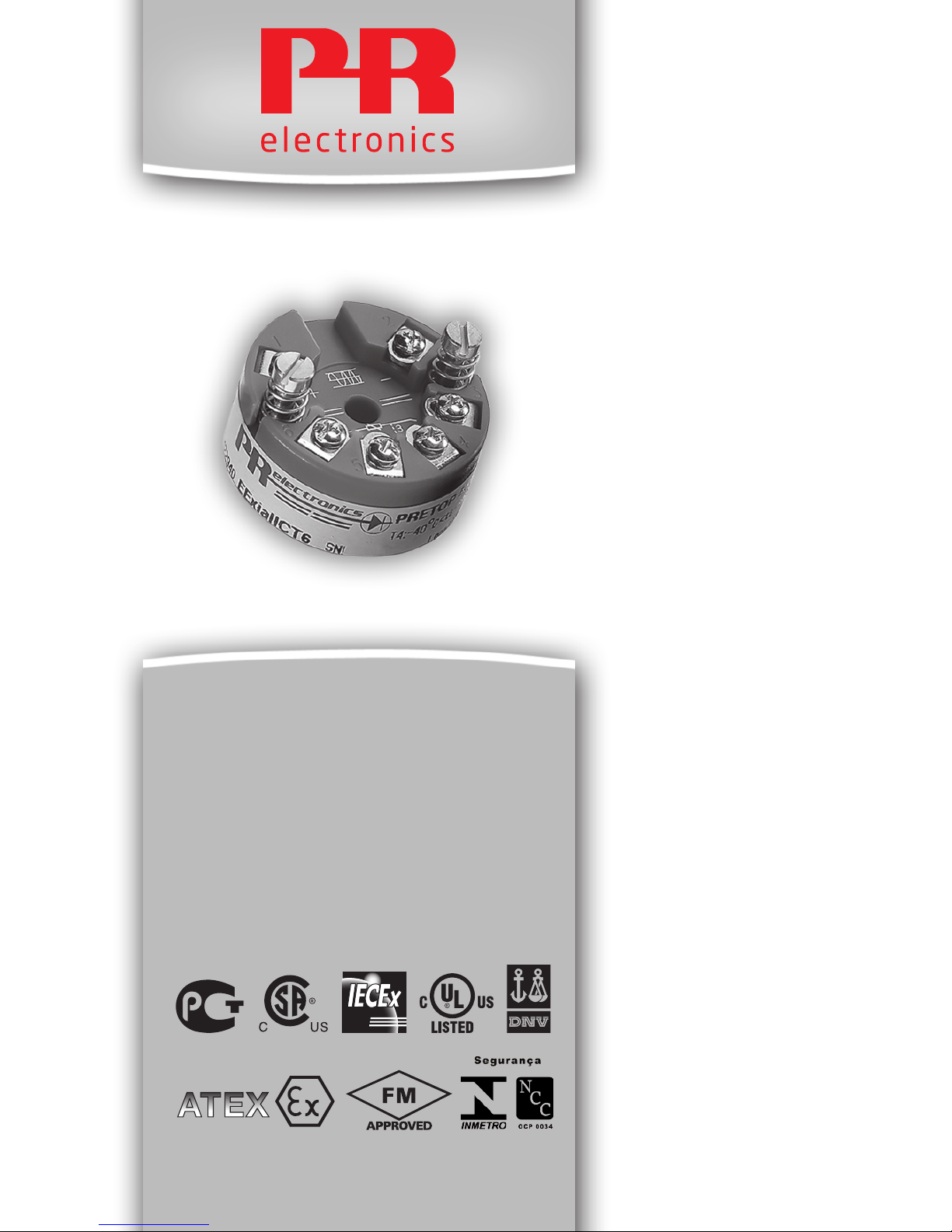
5335
2-Wire Transmitter
with HART® Protocol
No. 5335V116-UK
From ser. no. 120917001
Page 2

1433
PR electronics A/S tilbyder et bredt program af analoge og digitale
signalbehandlingsmoduler til industriel automation. Programmet
består af Isolatorer, Displays, Ex-barrierer, Temperaturtransmittere,
Universaltransmittere mfl. Vi har modulerne, du kan stole på i selv
barske miljøer med elektrisk støj, vibrationer og temperaturudsving,
og alle produkter opfylder de strengeste internationale standarder.
Vores motto »Signals the Best« er indbegrebet af denne filosofi – og
din garanti for kvalitet.
PR electronics A/S oers a wide range of analogue and digital
signal conditioning devices for industrial automation. The product
range includes Isolators, Displays, Ex Interfaces, Temperature
Transmitters, and Universal Devices. You can trust our products in
the most extreme environments with electrical noise, vibrations and
temperature fluctuations, and all products comply with the most
exacting international standards. »Signals the Best« is the epitome
of our philosophy – and your guarantee for quality.
PR electronics A/S ore une large gamme de produits pour le
traite ment des signaux analogiques et numériques dans tous
les domaines industriels. La gamme de produits s’étend des
transmetteurs de température aux acheurs, des isolateurs aux
interfaces SI, jusqu’aux modules universels. Vous pouvez compter
sur nos produits même dans les conditions d’utilisation sévères,
p.ex. bruit électrique, vibrations et fluctuations de température.
Tous nos produits sont conformes aux normes internationales les
plus strictes. Notre devise »SIGNALS the BEST« c’est notre ligne
de conduite - et pour vous l’assurance de la meilleure qualité.
PR electronics A/S verfügt über ein breites Produktprogramm
an analogen und digitalen Signalverarbeitungsgeräte für die industrielle Automatisierung. Dieses Programm umfasst Displays,
Temperaturtransmitter, Ex- und galvanische Signaltrenner, und
Universalgeräte. Sie können unsere Geräte auch unter extremen
Einsatzbedingungen wie elektrisches Rauschen, Erschütterungen
und Temperaturschwingungen vertrauen, und alle Produkte von
PR electronics werden in Überein stimmung mit den strengsten
internationalen Normen produziert. »Signals the Best« ist Ihre
Garantie für Qualität!
DK
UK
FR
DE
Page 3

5335V116-UK 1
2-WIRE TRANSMITTER
WITH HART® PROTOCOL
PRetop 5335
CONTENTS
Application ................................................................................................. 2
Technical characteristics ...................................................................... 2
Mounting / installation ......................................................................... 2
Applications............................................................................................... 3
Accessories ............................................................................................... 4
Order: 5335 ............................................................................................... 4
Electrical specifications........................................................................ 4
Connections .............................................................................................. 8
Block diagram ........................................................................................... 9
Programming ............................................................................................ 10
Connection of transmitters in multidrop mode .......................... 12
Mechanical specifications ................................................................... 12
Mounting of sensor wires ................................................................... 12
Appendix .................................................................................................... 13
ATEX Installation Drawing - 5335A ............................................ 14
IECEx Installation Drawing - 5335A ............................................ 16
ATEX Installation Drawing - 5335D ............................................ 17
IECEx Installation Drawing - 5335D ............................................ 19
FM Installation Drawing - 5335D ................................................. 21
CSA Installation Drawing - 5335D ............................................... 23
INMETRO Instruções de Segurança ............................................. 24
Page 4

2 5335V116-UK
2-WIRE TRANSMITTER
WITH HART® PROTOCOL
PRetop 5335
• RTD, TC, Ohm, or mV input
• Extremely high measurement accuracy
• HART
®
communication
• Galvanic isolation
• For DIN form B sensor head mounting
Application
• Linearised temperature measurement with Pt100...Pt1000, Ni100...Ni1000, or
TC sensor.
• Differenceoraveragetemperaturemeasurementof2resistanceorTCsensors.
• Conversionoflinearresistancevariationtoastandardanaloguecurrent
signal, for instance from valves or Ohmic level sensors.
• AmplificationofabipolarmVsignaltoastandard4...20mAcurrentsignal.
• Connectionofupto15transmitterstoadigital2-wiresignalwithHART
®
communication.
Technical characteristics
• Withina few seconds the user can program PR5335 to measure temperatures
within all ranges defined by the norms.
• TheRTDandresistanceinputshavecablecompensationfor2-,3-and4-wire
connection.
• The5335hasbeendesignedaccordingtostrictsafetyrequirementsandis
thus suitable for application in SIL 2 installations.
• Continuouscheckofvitalstoreddataforsafetyreasons.
• Sensorerror detection according to the guidelines in NAMUR NE 89.
Mounting / installation
• ForDINformB sensor head mounting. In non-hazardous areas the 5335 can be
mounted on a DIN rail with the PR fitting type 8421.
• NB: As Ex barrier for 5335D we recommend 5106B and 9106B.
Page 5
5335V116-UK 3
APPLICATIONS
+
-
+
-
V+
mA
V+
mA
+
-
+
-
V+
mA
+
-
+
-
V+
mA
V+
mA
+
-
+
-
+
-
+
-
+
-
+
-
+-
+-
+-
+-
2
1
2
2
1
1
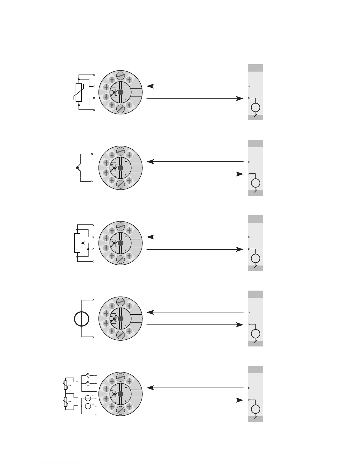
RTD to 4...20 mA
TC to 4...20 mA
Resistance to 4...20 mA
Dierence or average
RTD, TC or mV
2-wire installation
in control room
2-wire installation
in control room
2-wire installation
in control room
2-wire installation
in control room
mV to 4...20 mA
2-wire installation
in control room
Page 6
4 5335V116-UK
Electrical specifications
Specifications range:
-40°C to +85°C
Common specifications:
Supply voltage, DC
Standard ............................................................. 8.0...35 V
CSA, FM, ATEX, IECEx & INMETRO ........... 8.0...30 V
Isolation voltage, test / operation .................... 1.5 kVAC / 50 VAC
Warm-uptime ............................................................ 30 s
Communications interface ................................... HART
®
and Loop Link
Signal / noise ratio .................................................. Min. 60 dB
Response time (programmable) ......................... 1...60 s
EEprom error check ................................................. < 10 s
Signal dynamics, input ........................................... 22 bit
Signal dynamics, output ....................................... 16 bit
Calibration temperature ........................................ 20...28°C
Accuracy, the greater of general and basic values:
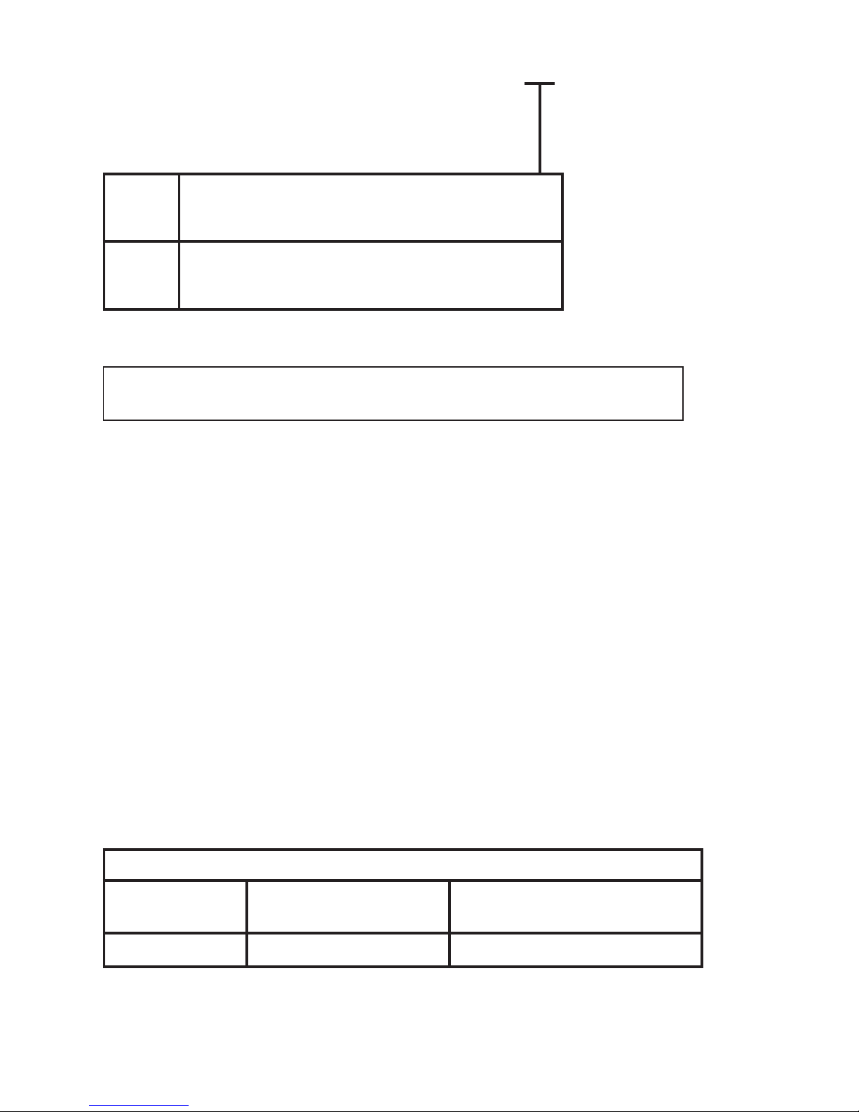
Order: 5335
Type Version
5335 Standard : A
CSA, FM, ATEX, IECEx & INMETRO : D
General values
Input type
Absolute
accuracy
Temperature
coefficient
All ≤ ±0.05% of span ≤ ±0.005% of span / °C
5909 = Loop Link USB interface and PReset Software
8421 = DIN rail clip
Accessories
Page 7

5335V116-UK 5
Effect of supply voltage variation .................... < 0.005% of span / VDC
Vibration ...................................................................... IEC 60068-2-6 Test FC
2...25Hz .............................................................
±1.6 mm
25...100Hz .................................................. ±4 g
Max. wire size ............................................................ 1 x 1.5 mm
2
stranded wire
Screw terminal torque ........................................... 0.4 Nm
Relative humidity..................................................... <95%RH(non-cond.)
Dimensions ................................................................. Ø 44 x 20.2 mm
Protection degree (enclosure / terminals) ..... IP68 / IP00
Weight .......................................................................... 50 g
Basic values
Input type
Basic
accuracy
Temperature
coefficient
Pt100 & Pt1000 ≤ ±0.1°C ≤ ±0.005°C/°C
Ni100 ≤ ±0.2°C ≤ ±0.005°C/°C
Lin. R ≤ ±0.1 Ω ≤ ±5 mΩ / °C
Volt ≤ ±10 µV ≤ ±0.5 µV / °C
TC type:
E, J, K, L, N, T, U
≤ ±0.5°C
≤ ±0.025°C / °C
TC type:
B,R,S,W3,W5
≤ ±1°C
≤ ±0.1°C / °C
EMC immunity influence .................................................. < ±0.1% of span
Extended EMC immunity:
NAMUR NE 21, A criterion, burst ................................. < ±1% of span
Page 8

6 5335V116-UK
Electrical specifications, input:
Max. offset ................................................................. 50% of selec. numerical max. value
RTD and linear resistance input:
Cable resistance per wire (max.) ....................... 5 Ω
(up to 50 Ω per wire is possible with reduced measurement accuracy)
Sensor current ........................................................... Nom. 0.2 mA
Effect of sensor cable resistance (3- / 4-wire) .... < 0.002 Ω/Ω
Sensor error detection ........................................... Yes
Short circuit detection ........................................... If 0% > 30 Ω
TC input:
Cold junction compensation ................................ < ±1.0°C
External CJC with Ni100 or Pt100 ................... -40 ≤ T
amb.
≤ 135°C
Sensor error detection ........................................... Yes
Sensor error current:
Whendetecting ............................................... Nom. 33 μA
Else ....................................................................... 0 μA
Short circuit detection ........................................... No
Type
Min.
temperature
Max.
temperature
Min.
span
Standard
B
E
J
K
L
N
R
S
T
U
W3
W5
+400°C
-100°C
-100°C
-180°C
-100°C
-180°C
-50°C
-50°C
-200°C
-200°C
0°C
0°C
+1820°C
+1000°C
+1200°C
+1372°C
+900°C
+1300°C
+1760°C
+1760°C
+400°C
+600°C
+2300°C
+2300°C
100°C
50°C
50°C
50°C
50°C
50°C
100°C
100°C
50°C
50°C
100°C
100°C
IEC584
IEC584
IEC584
IEC584
DIN 43710
IEC584
IEC584
IEC584
IEC584
DIN 43710
ASTM E988-90
ASTM E988-90
RTD
type
Min.
value
Max.
value
Min.
span Standard
Pt100
Ni100
Lin. R
-200°C
-60°C
0 Ω
+850°C
+250°C
7000 Ω
10°C
10°C
25 Ω
IEC 60751
DIN 43760
-----
Page 9

5335V116-UK 7
Voltage input:
Measurement range ................................................ -800...+800 mV
Min. span ..................................................................... 2.5 mV
Input resistance........................................................ 10 MΩ
Current output:
Signal range ............................................................... 4...20 mA
Min. signal range ...................................................... 16 mA
Updating time ........................................................... 440 ms
(660 ms for diff.)
Fixed output signal ................................................. Between 4 and 20 mA
Output signal at EEprom error ............................ ≤ 3.5 mA
Load resistance......................................................... ≤ (V
supply
- 8) / 0.023 [Ω ]
Load stability ............................................................. < ±0.01% of span / 100 Ω
Sensor error detection:
Programmable ........................................................... 3.5...23 mA
(shorted sensor error detection is ignored at TC and mV input)
NAMUR NE43 Upscale ........................................... 23 mA
NAMUR NE43 Downscale ..................................... 3.5 mA
Of span = Of the presently selected range
Approvals:
EMC 2004/108/EC .................................................. EN 61326-1
GOST R
Marine approval:
Det Norske Veritas, Ships & Offshore ............. Stand. for Certific. No. 2.4
Ex / I.S.:
5335A:
ATEX 94/9/EC .................................................. KEMA 03ATEX1508 X
IECEx .................................................................... KEM 10.0083 X
5335D:
ATEX 94/9/EC .................................................. KEMA 03ATEX1537
IECEx .................................................................... KEM 10.0083 X
FM ......................................................................... 2D5A7
CSA ....................................................................... 1125003
INMETRO ............................................................ NCC 12.0844 X
GOST Ex
Functional Safety:
HardwareassessedforuseinSILapplications
FMEDA report - www.prelectronics.com
Page 10
8 5335V116-UK
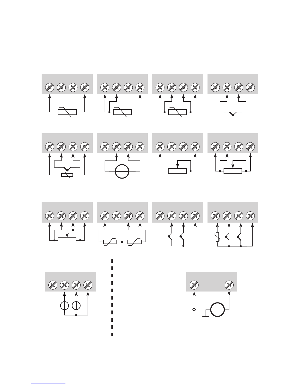
CONNECTIONS
3
4
65 3
4
65 3
4
65 3
4
65
+
-
3
4
65
+
-
3
4
65
+
-
3
4
65 3
4
65
3
4
65 3
4
65
12
3
4
65
+
-
1
+
-
2
3
4
65
+-+
-
12
3
4
65
+
-
+
-
1 2
mA -
+
2 1
Output:
2-wire installation
Input:
Resistance, 2-wire Resistance, 3-wire
RTD, 2-wire RTD, 3-wire RTD, 4-wire
TC, internal CJC
TC, external CJC mV
Resistance, 4-wire
TC, dierence
or average,
with external CJC
mV, dierence
or average
RTD, dierence
or average
TC, dierence
or average,
with internal CJC
Page 11
5335V116-UK 9
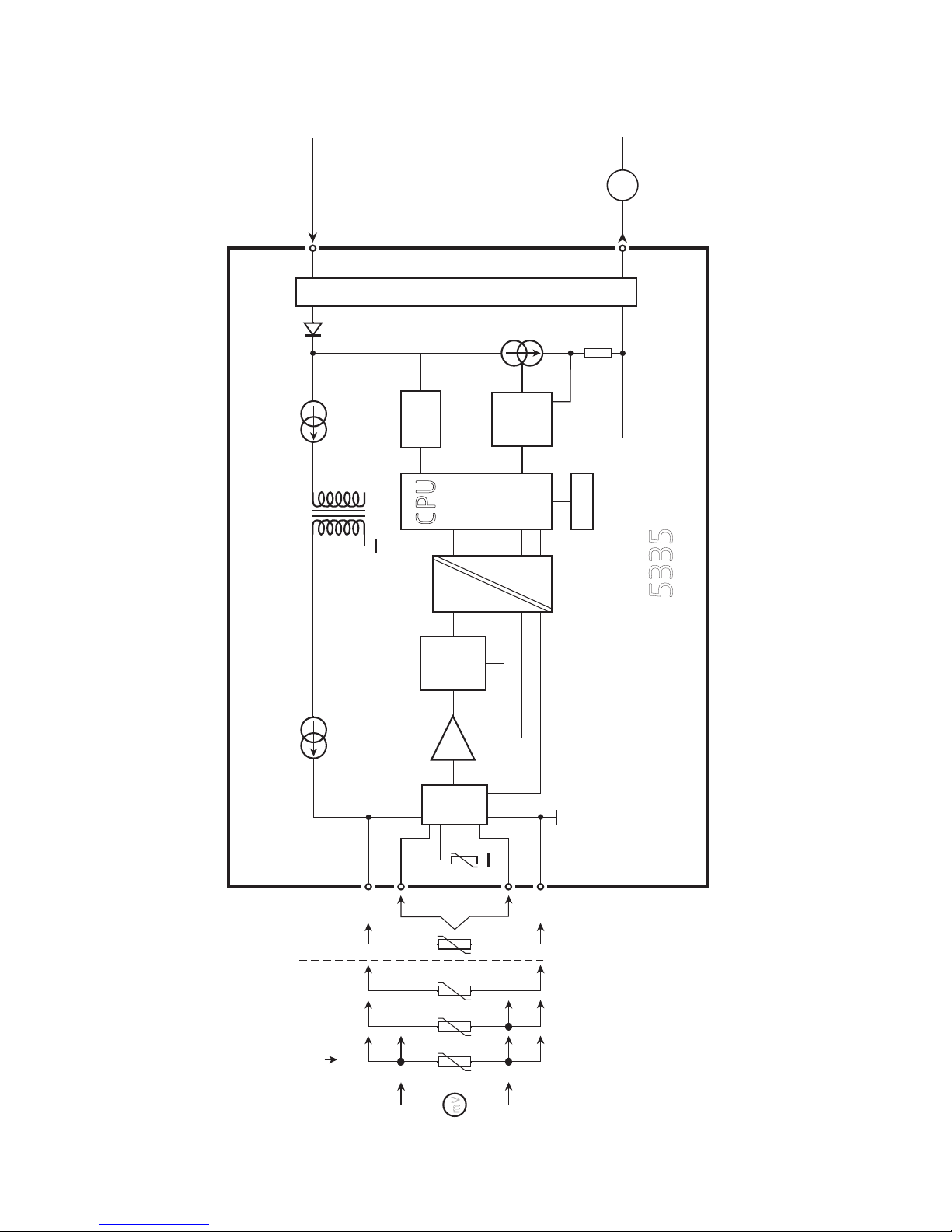
BLOCK DIAGRAM
0.. .16
mA
4
3
2
1
5
6
4
3
2
+
-
+
-
mV
mA
M UX
4 mA
5335
PGA
D / A
A / D
C PU
EE PRO M
Input gnd.
Supply -
4...20 mA
TC
Ext.
CJC
mV
RTD, lin. R
- wire
Int.
CJC
Ex circuit, only 5335D
Supply +
8.0...35 VDC
Comm.
Page 12
10 5335V116-UK
PROGRAMMING
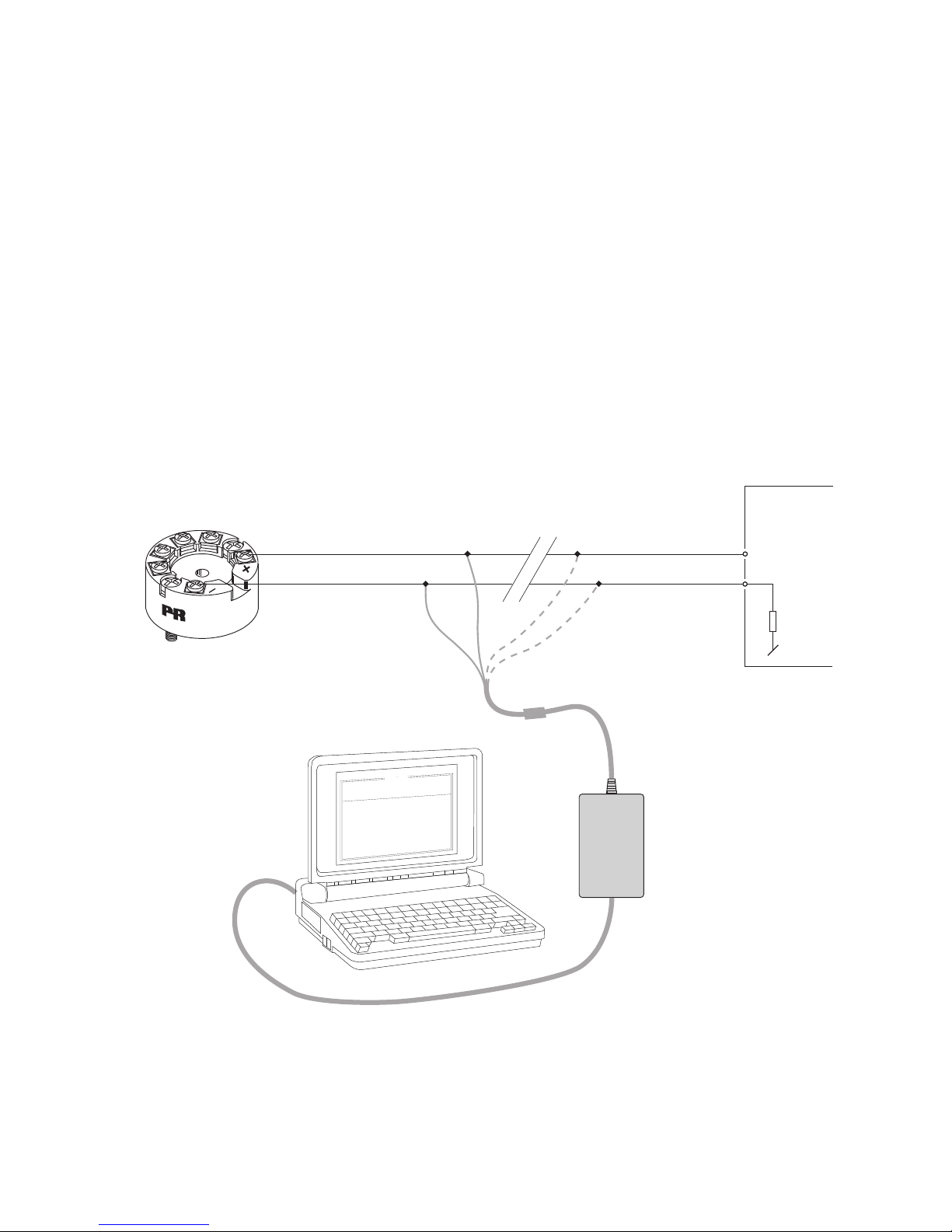
PRetop 5335 can be configured in the following 3 ways:
1.WithPRelectronicsA/S’communicationsinterfaceLoopLinkandPResetPC
configuration software.
2.WithaHART
®
modem and PReset PC configuration software.
3.WithaHART® communicator with PR electronics A/S’ DDL driver.
1: Loop Link
For programming please refer to the drawing below and the help functions in
PReset.
Loop Link is not approved for communication with modules installed in
hazardous (Ex) areas.
1
2
*
*
PRetop 5335
Loo p
Link
5909 - USB
F
i
l
e
P
r
o
d
u
c
t
I
n
p
u
t
O
u
t
p
u
t
C
o
m
m
u
n
i
c
at
i
o
n
L
a
n
g
u
ag
e
O
p
t
i
o
n
0
8
:
3
0
:
0
0
P
R
e
t
o
p
5
3
3
1
D
at
e
:
2
0
0
4
-
8
-
1
0
0
4
3
2
0
1
5
9
4
P
R
e
l
e
ct
r
o
n
i
c
s
A
n
al
o
g
i
n
p
u
t
A
n
al
o
g
o
u
t
p
u
t
S
e
r
i
al
n
o
:
I
n
p
u
t
t
yp
e
:
O
u
t
p
u
t
t
y
p
e
:
4
-
2
0
m
A
U
p
s
c
al
e
S
e
n
s
o
r
e
r
r
o
r
:
P
t
1
0
0
D
I
N
/
I
E
C
0
.
0
0
-
5
0
.
0
0
C
3
-
w
i
r
e
1
.
0
0
s
e
c
-
-
-
-
-
-
I
n
p
u
t
r
an
g
e
:
C
o
n
n
e
ct
i
o
n
:
C
o
l
d
j
u
n
c
t
i
o
n
c
o
m
p
:
R
e
s
p
o
n
se
t
i
m
e
:
T
ag
n
o
:
Disconnect
+Vsupply
* Connected only for
on-line programming
Black
Red
Yellow
Green
Input
Receiving
Equipment
Connector
Page 13
5335V116-UK 11
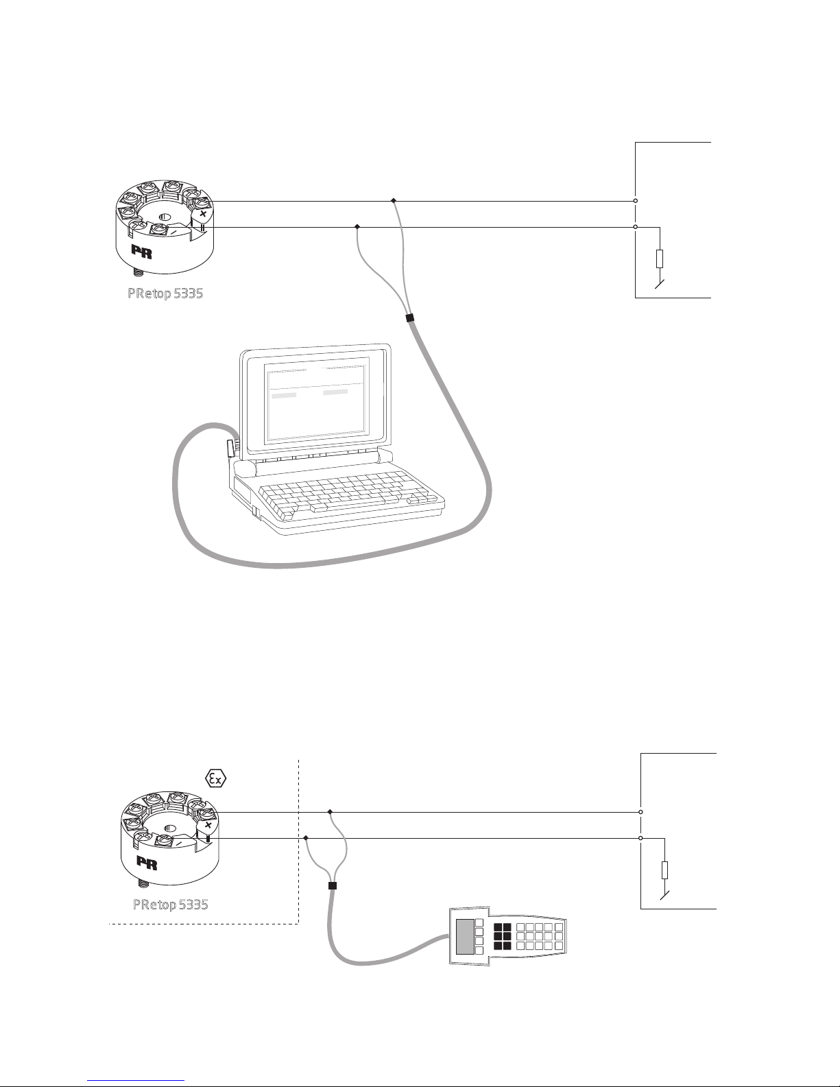
2: HART® modem
For programming please refer to the drawing below and the help functions in
PReset.
3: HART
®
communicator
For programming please refer to the drawing below. To gain access to
product-specificcommands,theHART
®
communicator must be loaded with
thePRelectronicsA/SDDLdriver.ThiscanbeorderedeitherattheHART
®
Communica tion Foundation or at PR electronics A/S.
PRetop 5335
1
2
F
i
l
e
P
r
o
d
u
c
t
I
n
p
u
t
O
u
t
p
u
t
C
o
m
m
u
n
i
c
a
t
i
o
n
L
a
n
g
u
a
g
e
O
p
t
i
o
n
0
8
:
3
0
:
0
0
P
R
e
t
o
p
5
3
3
1
D
a
t
e
:
1
9
9
4
-
8
-
1
0
9
4
3
2
0
1
5
9
4
P
R
e
l
e
c
t
r
o
n
i
c
s
A
n
a
l
o
g
i
n
p
u
t
A
n
a
l
o
g
o
u
t
p
u
t
S
e
r
i
a
l
n
o
:
I
n
p
u
t
t
y
p
e
:
O
u
t
p
u
t
t
y
p
e
:
4
-
2
0
m
A
U
p
s
c
a
l
e
S
e
n
s
o
r
e
r
r
o
r
:
P
t
1
0
0
D
I
N
/
I
E
C
0
.
0
0
-
5
0
.
0
0
C
3
-
w
i
r
e
1
.
0
0
s
e
c
-
-
-
-
-
-
I
n
p
u
t
r
a
n
g
e
:
C
o
n
n
e
c
t
i
o
n
:
C
o
l
d
j
u
n
c
t
i
o
n
c
o
m
p
:
R
e
s
p
o
n
s
e
t
i
m
e
:
T
a
g
n
o
:
+Vsupply
Input
Receiving
Equipment
Rload > 250 Ω, < 1100 Ω
HART
®
modem
PRetop 5335
1
2
Safe area
+Vsupply
Input
Receiving
Equipment
area
Rload
> 250 Ω, < 1 100 Ω
Page 14
2 0 . 2 m m
+
-
+
-
ø 6 mm
33 mm
ø 44 mm
12 5335V116-UK
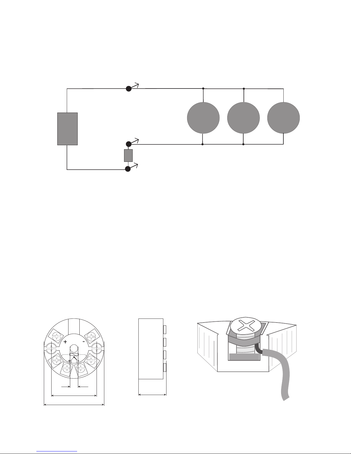
CONNECTION OF TRANSMITTERS IN
MULTIDROP MODE
TheHART® communicator or a PC modem can be connected accross AB or BC.
The outputs of max. 15 transmitters can be connected in parallel for a digital
HART
®
communication on 2-wires.
Before it is connected, each transmitter must be configured with a unique number
from 1 to 15. If 2 transmitters are configured with the same number, both will
be excluded. The transmitters must be programmed for multidrop mode (with a
fixed output signal of 4 mA). Maximum current in the loop is therefore 60 mA.
The communication is either by means of a HART
®
communicator or a HART®
modem.
The PReset PC configuration software can configure the individual transmitter for
multidrop mode and provide it with a unique polling address.
Mechanical specifications Mounting of sensor wires
R
A
B
C
PRetop
5335
+
-
+
-
PRetop
5335
PRetop
5335
Power
supply
Max. 15 transmitters
Rload
> 250 Ω, < 1100 Ω
Wiresmustbemountedbetweenthemetal
plates.
Page 15

APPENDIX
ATEX Installation Drawing - 5335A
ATEX Installation Drawing - 5335D
IECEx installation drawing - 5335A
IECEx installation drawing - 5335D
FM Installation Drawing - 5335D
CSA Installation Drawing - 5335D
INMETRO Instruções de Segurança - 5335D
5335V116-UK 13
Page 16
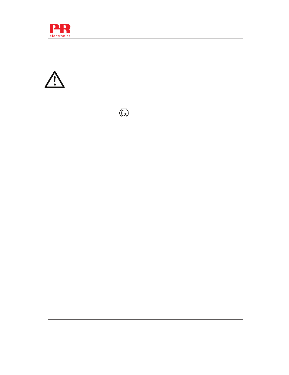
14 5335V116-UK
5335QE01
LERBAKKEN 10, 8410 RØNDE DENMARK. WWW.PRELECTRONICS.COM
Doc. No.
5335QA02 V4R0
Page:
1/2
ATEX Installation drawing 5335QA02
For safe installation of 5335A or 5337A the following must be observed. The module shall only be
installed by qualified personnel who are familiar with the national and international laws,
directives and standards that apply to this area.
Year of manufacture can be taken from the first two digits in the serial number.
ATEX Certificate KEMA 03ATEX 1508X
Marking
Standards EN60079-0:2012, EN60079-11:2012, EN60079-15:2010
General installation instructions
If the enclosure is made of non-metallic materials or of painted metal, electrostatic charging
shall be avoided.
For an ambient temperature ≥ 60ºC, heat resistant cables shall be used with a rating of at
least 20 K above the ambient temperature.
For installation in a potentialy explosive gas atmosphere, the following instructions apply:
For “Ex ic” the transmitter must be installed in an enclosure providing a degree of protection of
at least IP20 according to EN60529 that is suitable for the application and is correctly
installed.
For “Ex nA” the transmitter must be installed in an enclosure providing a degree of protection
of at least IP54 according to EN60529 that is suitable for the application and is correctly
installed, or in an enclosure with type of protection Ex n or Ex e.
Cable entry devices and blanking elements shall fulfill the same requirements
For installation in a potentially explosive dust atmposphere, the following instructions apply:
If the transmitter is supplied with an intrinsically safe signal "ic" and interfaces an intrinsically
safe signal "ic" (e.g. a passive device), the transmitter shall be mounted in a metal enclosure
form B according to DIN 43729 that provides a degree of protection of at least IP6X according
to EN60529, and that is suitable for the application. Cable entry devices and blanking
elements shall fulfill the same requirements.
T4: -40 ≤ Ta ≤ 85ºC
T6: -40 ≤ Ta ≤ 60ºC
II 3 G Ex nA [ic] IIC T6..T4 Gc
II 3 G Ex ic IIC T6..T4 Gc
II 3 D Ex ic IIIC Dc
Terminal: 3,4,5,6
Ex nA [ic]
Uo: 9.6 V
Io: 28 mA
Po: 67 mW
Lo: 45 mH
Co: 28 μF
Terminal: 1,2
Ex nA
U ≤ 35 VDC
I = 4 - 20 mA
Terminal: 1,2
Ex ic
Ui = 35 VDC
Li = 10 μH
Ci = 1.0 nF
Page 17

5335V116-UK 15
5335QE01
LERBAKKEN 10, 8410 RØNDE DENMARK. WWW.PRELECTRONICS.COM
Doc. No.
5335QA02 V4R0
Page:
2/2
If the transmitter is supplied with an non-sparking signal "nA", or interfaces a non
sparking signal, the transmitter shall be mounted in a metal enclosure form B according to
DIN 43729 providing a degree of protection of at least IP6X according to EN60529, and in
conformance with type of protection Ex tD and suitable for the application. Cable entry
devices and blanking elements shall fulfill the same requirements.
Page 18
5335QE01
LERBAKKEN 10, 8410 RØNDE DENMARK. WWW.PRELECTRONICS.COM
Doc. No.
5335QI02 V4R0
Page:
1/1
IECEx Installation drawing 5335QI02
For safe installation of 5335A or 5337A the following must be observed. The module shall only be
installed by qualified personnel who are familiar with the national and international laws,
directives and standards that apply to this area.
Year of manufacture can be taken from the first two digits in the serial number.
IECEx Certificate IECEx KEM 10.0083X
Marking
Standards IEC 60079-0 : 2011, IEC 60079-11 : 2011, EN 60079-15 : 2010
General installation instructions
If the enclosure is made of non-metallic materials or of painted metal, electrostatic charging
shall be avoided.
For an ambient temperature ≥ 60ºC, heat resistant cables shall be used with a rating of at
least 20 K above the ambient temperature.
For installation in a potentialy explosive gas atmosphere, the following instructions apply:
For “Ex ic” the transmitter must be installed in an enclosure providing a degree of protection of
at least IP20 according to IEC60529 that is suitable for the application and is correctly
installed.
For “Ex nA” the transmitter must be installed in an enclosure providing a degree of protection
of at least IP54 according to IEC60529 that is suitable for the application and is correctly
installed, or in an enclosure with type of protection Ex n or Ex e.
Cable entry devices and blanking elements shall fulfill the same requirements
For installation in a potentially explosive dust atmposphere, the following instructions apply:
If the transmitter is supplied with an intrinsically safe signal "ic" and interfaces an intrinsically
safe signal "ic" (e.g. a passive device), the transmitter shall be mounted in a metal enclosure
form B according to DIN 43729 that provides a degree of protection of at least IP6X according
to IEC60529, and that is suitable for the application. Cable entry devices and blanking
elements shall fulfill the same requirements.
If the transmitter is supplied with an non-sparking signal "nA", or interfaces a non
sparking signal, the transmitter shall be mounted in a metal enclosure form B according to
DIN 43729 providing a degree of protection of at least IP6X according to IEC60529, and in
conformance with type of protection Ex tD and suitable for the application. Cable entry
devices and blanking elements shall fulfill the same requirements.
T4: -40 ≤ Ta ≤ 85ºC
T6: -40 ≤ Ta ≤ 60ºC
Ex nA [ic] IIC T6..T4 Gc
Ex ic IIC T6..T4 Gc
Ex ic IIIC Dc
Terminal: 3,4,5,6
Ex nA [ic]
Uo: 9.6 V
Io: 28 mA
Po: 67 mW
Lo: 45 mH
Co: 28 μF
Terminal: 1,2
Ex nA
U ≤ 35 VDC
I = 4 - 20 mA
Terminal: 1,2
Ex ic
Ui = 35 VDC
Li = 10 μH
Ci = 1.0 nF
16 5335V116-UK
Page 19
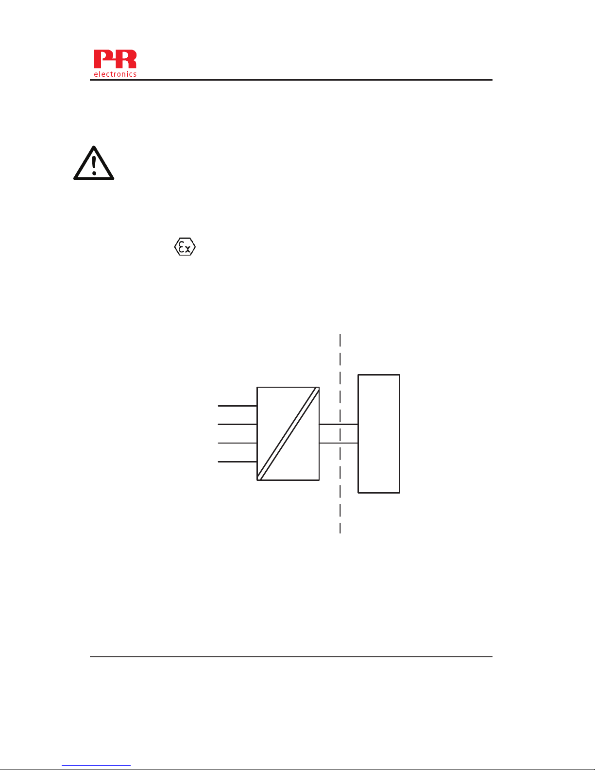
5335V116-UK 17
5335QE01
LERBAKKEN 10, 8410 RØNDE DENMARK. WWW.PRELECTRONICS.COM
Doc. No.
5335QA01 V4R0
Page:
1/2
ATEX Installation drawing 5335QA01
For safe installation of 5335D or 5337D the following must be observed. The module shall only be
installed by qualified personnel who are familiar with the national and international laws, directives
and standards that apply to this area.
Year of manufacture can be taken from the first two digits in the serial number.
ATEX Certificate KEMA 03ATEX 1537
Marking
Standards: EN 60079-0 : 2012, EN 60079-11 : 2012, EN 60079-26 : 2007
Non Hazardous Area
Hazardous area
Zone 0, 1, 2, 20, 21, 22, and Coal mining
T4: -40 ≤ Ta ≤ 85ºC
T6: -40 ≤ Ta ≤ 60ºC
II 1 G Ex ia IIC T6 ...T4 Ga
II 1 D Ex ia IIIC Da
I M1 Ex ia I Ma
1
2
6
5
4
3
+
-
Barrier
5335D
5337D
Terminal: 3,4,5,6
Uo: 9.6 VDC
Io: 28 mA
Po: 67 mW
Lo: 35 mH
Co: 3.5μF
Terminal: 1,2
Ui: 30 VDC
Ii: 120 mA
Pi: 0.84 W
Li: 10μH
Ci: 1.0nF
Page 20

18 5335V116-UK
5335QE01
LERBAKKEN 10, 8410 RØNDE DENMARK. WWW.PRELECTRONICS.COM
Doc. No.
5335QA01 V4R0
Page:
2/2
Installation notes
General installation instructions
The sensor circuit is not infallibly galvanic isolated from the supply output circuit. However, the
galvanic isolation between the circuits is capable of withstanding a test voltage of 500Vac
during 1 minute.
If the enclosure is made of aluminium, it must be installed such, that even in the event of rare
incidents, ignition sources due to impact and friction, sparks are excluded.
If the enclosure is made of non-metallic materials or painted metals electrostatic charging shall
be avoided
For installation in a potentially explosive gas atmosphere, the following instructions apply:
The transmitter shall be mounted in an enclosure form B according to DIN43729 or equivalent
that is providing a degree of protection of at least IP20 according to EN60529 that is suitable
for the application and correctly installed.
For installation in a potentially explosive dust atmosphere, the following instructions apply:
The transmitter shall be mounted in a metal enclosure form B according to DIN43729 or
equivalent, that is providing a degree of protection of at least IP6X according to EN60529 that
is suitable for the application and correctly installed.
Cable entries and blanking elements shall be used that are suitable for the application and
correctly installed.
For installalation in mines the following instructions apply:
The transmitter shall be mounted in a metal enclosure that is providing a degree of protection
of at least IP6X according to EN60529, and is suitable for the application and correctly
installed.
Cable entries and blanking elements shall be used that are suitable for the application and
correctly installed
If the enclosure is made of aluminum, it must be installed such, that even in the event of rare
incidents, ignition sources due to impact and friction, sparks are excluded.
If the enclosure is made of non-metallic materials or painted metals electrostatic charging shall
be avoided.
The enclosure shall not contain by mass more than
a) 15 % in total of aluminium, magnesium, titanium and zirconium, and
b) 7,5 % in total of magnesium, titanium and zirconium.
Page 21
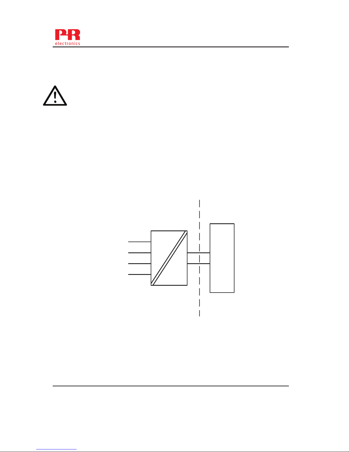
5335QE01
LERBAKKEN 10, 8410 RØNDE DENMARK. WWW.PRELECTRONICS.COM
Doc. No.
5335QI01 V4R0
Page:
1/2
IECEx Installation drawing 5335QI01
For safe installation of 5335D or 5337D the following must be observed. The module shall only be
installed by qualified personnel who are familiar with the national and international laws, directives
and standards that apply to this area.
Year of manufacture can be taken from the first two digits in the serial number.
IECEx Certificate IECEx KEM.10.0083X
Marking
Standards IEC60079-11:2011, IEC60079-0: 2011, IEC60079-26:2006
Non Hazardous Area
Hazardous area
Zone 0, 1, 2, 20, 21, 22 and Coal mining
T4: -40 ≤ Ta ≤ 85ºC
T6: -40 ≤ Ta ≤ 45ºC
Ex ia IIC T6..T4 Ga
Ex ia IIIC Da
Ex ia I Ma
1
2
6
5
4
3
+
-
Barrier
5335D
5337D
Terminal: 3,4,5,6
Uo: 9.6 VDC
Io: 28 mA
Po: 67 mW
Lo: 35 mH
Co: 3.5 μF
Terminal: 1,2
Ui: 30 VDC
Ii: 120 mA
Pi: 0.84 W
Li: 10 μH
Ci: 1.0 nF
5335V116-UK 19
Page 22

5335QE01
LERBAKKEN 10, 8410 RØNDE DENMARK. WWW.PRELECTRONICS.COM
Doc. No.
5335QI01 V4R0
Page:
2/2
Installation notes
General installation instructions
The sensor circuit is not infallibly galvanic isolated from the supply output circuit. However, the
galvanic isolation between the circuits is capable of withstanding a test voltage of 500Vac
during 1 minute.
If the enclosure is made of aluminium, it must be installed such, that even in the event of rare
incidents, ignition sources due to impact and friction, sparks are excluded.
If the enclosure is made of non-metallic materials or painted metals electrostatic charging shall
be avoided
For installation in a potentially explosive gas atmosphere, the following instructions apply:
The transmitter shall be mounted in an enclosure form B according to DIN43729 or equivalent
that is providing a degree of protection of at least IP20 according to IEC 60529 that is suitable
for the application and correctly installed.
For installation in a potentially explosive dust atmosphere, the following instructions apply:
The transmitter shall be mounted in a metal enclosure form B according to DIN43729 or
equivalent, that is providing a degree of protection of at least IP6X according to IEC 60529 that
is suitable for the application and correctly installed.
Cable entries and blanking elements shall be used that are suitable for the application and
correctly installed.
For installalation in mines the following instructions apply:
The transmitter shall be mounted in a metal enclosure that is providing a degree of protection
of at least IP6X according to IEC 60529, and is suitable for the application and correctly
installed.
Cable entries and blanking elements shall be used that are suitable for the application and
correctly installed
If the enclosure is made of aluminium, it must be installed such, that even in the event of rare
incidents, ignition sources due to impact and friction, sparks are excluded.
If the enclosure is made of non-metallic materials or painted metals electrostatic charging shall
be avoided.
The enclosure shall not contain by mass more than
a) 15 % in total of aluminium, magnesium, titanium and zirconium, and
b) 7,5 % in total of magnesium, titanium and zirconium.
20 5335V116-UK
Page 23
5335QE01
LERBAKKEN 10, 8410 RØNDE DENMARK. WWW.PRELECTRONICS.COM
Revision date:
2014-03-31
Version Revision
V4R0
Page:
1/5
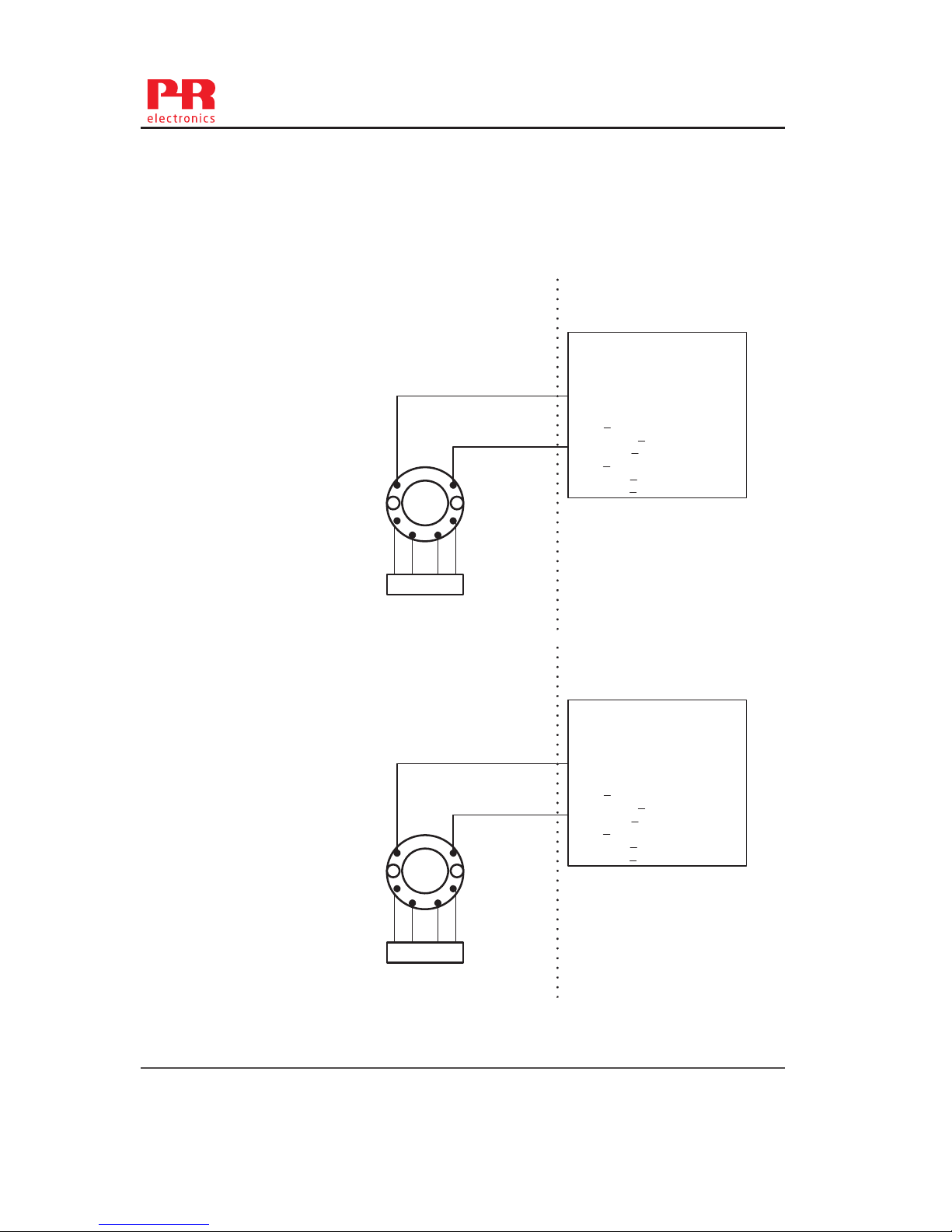
FM Installation Drawing 5300Q502 Rev AH
Model 5331C,5331D, 5333C, 5333D and 5343B
Model 5335C, 5335D, 5336D, 5337D
NonHazardousLocation
Hazardous(Classified)Location
Associated Apparatus
or Barrier
with
entity Parameters:
SENSOR
1
2
3
45
6
UM < 250V
Voc or Uo < Vmax or Ui
Isc or Io < Imax or Ii
Po < Pi
Ca or Co > Ci + Ccable
La or Lo > Li + Lcable
Thisdevicemustnotbeconnected
toanyassociatedapparatuswhich
usesorgeneratesmorethan 250
VRMS
+
‐
Terminal 1 , 2
Vmax or Ui: 30 V
Imax or Ii: 120 mA
Pmax or Pi: 0.84 W
Ci: 1 nF
Li:10 uH
Terminal 3,4,5,6
Only passive, or non-energy
storing devices such as RTD's
and Thermocouples may be
connected.
Ambienttemperaturelimits
T4:‐40to+85deg.Celcius
T6:‐40to+60deg.Celcius
Class I,Division1, Groups, A,B,C,D
Class I, Zone 0, IIC
NonHazardousLocation
Hazardous(Classified)Location
Associated Apparatus
or Barrier
with
entity Parameters:
SENSOR
1
2
3
45
6
UM < 250V
Voc or Uo < Vmax or Ui
Isc or Io < Imax or Ii
Po < Pi
Ca or Co > Ci + Ccable
La or Lo > Li + Lcable
Thisdevicemustnotbeconnected
toanyassociatedapparatuswhich
usesorgeneratesmorethan 250
VRMS
+
‐
Terminal 1 , 2
Vmax or Ui: 30 V
Imax or Ii: 120 mA
Pmax or Pi: 0.84 W
Ci: 1 nF
Li:10 uH
Terminal 3,4,5,6
Vt or Uo: 9.6 V
It or Io: 28 mA
Pt or Po: 67.2 mW
Ca or Co: 3.5 uF
La or Lo: 35 mH
Ambienttemperaturelimits
T4:‐40to+85deg.Celcius
T6:‐40to+60deg.Celcius
Class I,Division1, Groups, A,B,C,D
Class I, Zone 0, IIC
5335V116-UK 21
Page 24
5335QE01
LERBAKKEN 10, 8410 RØNDE DENMARK. WWW.PRELECTRONICS.COM
Revision date:
2014-03-31
Version Revision
V4R0
Page:
2/5
The entity concept
The Transmitter must be installed according to National Electrical Code (ANSI-NFPA 70) and shall be
installed with the enclosure, mounting, and spacing segregation requirement of the ultimate application.
Equipment that is FM-approved for intrinsic safety may be connected to barriers based on the ENTITY
CONCEPT. This concept permits interconnection of approved transmitters, meters and other devices in
combinations which have not been specifically examined by FM, provided that the agency's criteria are
met. The combination is then intrinsically safe, if the entity concept is acceptable to the authority having
jurisdiction over the installation.
The entity concept criteria are as follows:
The intrinsically safe devices, other than barriers, must not be a source of power.
The maximum voltage Ui(V
MAX
) and current Ii(I
MAX
), and maximum power Pi(Pmax), which the device can
receive and remain intrinsically safe, must be equal to or greater than the voltage (Uo or V
OC
or Vt) and
current (Io or I
SC
or It) and the power Po which can be delivered by the barrier.
The sum of the maximum unprotected capacitance (C
i
) for each intrinsically device and the interconnect-
ing wiring must be less than the capacitance (C
a
) which can be safely connected to the barrier.
The sum of the maximum unprotected inductance (L
i
) for each intrinsically device and the interconnecting
wiring must be less than the inductance (L
a
) which can be safely connected to the barrier.
The entity parameters Uo,V
OC
or Vt and Io,ISC or It, and Ca and La for barriers are provided by the barrier
manufacturer.
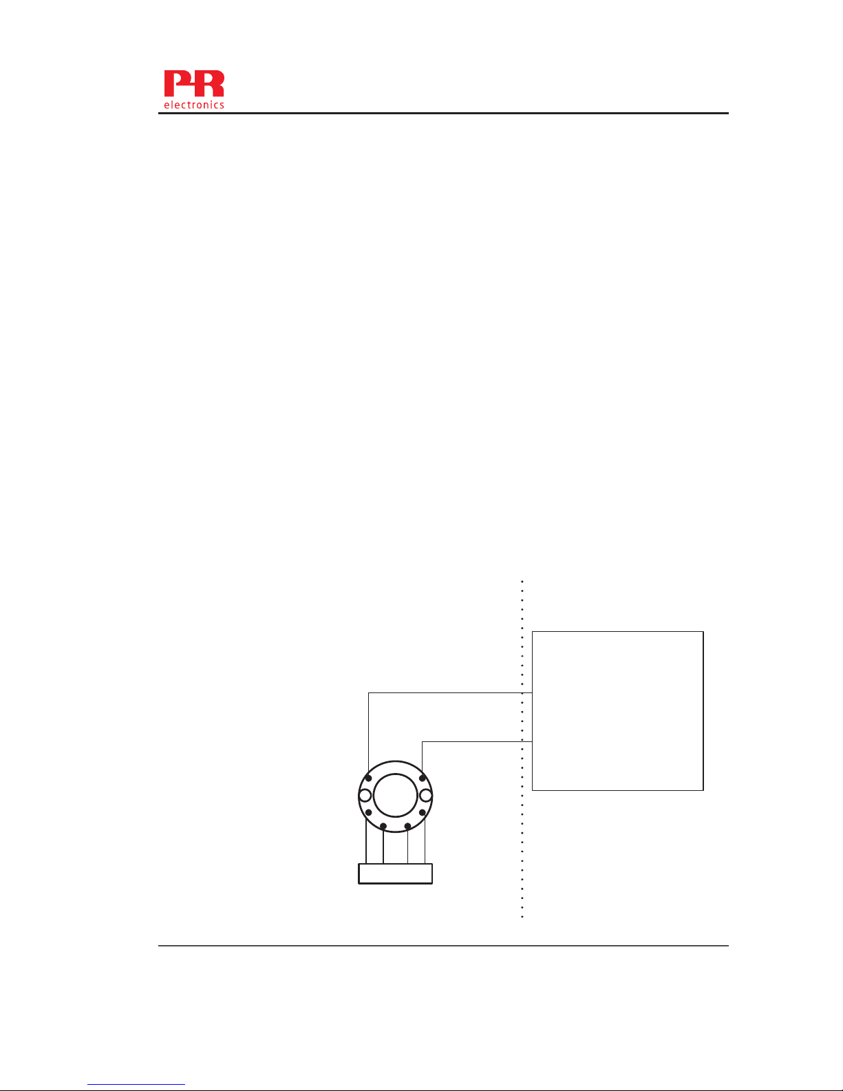
NI Field Circuit Parameters
Model 5331C, 5331D, 5333C, 5333D, 5335C, 5335D, 5336D, 5337D and
5343B
NonHazardousLocation
Hazardous(Classified)Location
Associated Apparatus
or Barrier
SENSOR
1
2
3
45
6
Thisdevicemustnotbeconnected
toanyassociatedapparatuswhich
usesorgeneratesmorethan250
VRMS
+
‐
Terminal 1 , 2
Vmax : 35 V
Ci: 0 µ F
Li:10 uH
Ambienttemperaturelimits
T4:‐40to+85deg.Celcius
T6:‐40to+60deg.Celcius
Class I,Division2, Groups, A,B,C,D
Class I, Zone 2, IIC
22 5335V116-UK
Page 25
5335QE01
LERBAKKEN 10, 8410 RØNDE DENMARK. WWW.PRELECTRONICS.COM
Revision date:
2014-03-31
Version Revision
V4R0
Page:
3/5
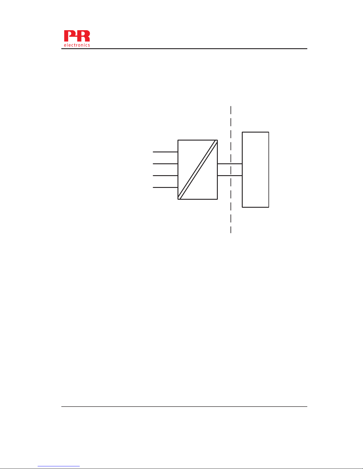
CSA Installation drawing 533XQC03
CLASS 2258 04 - PROCESS CONTROL EQUIPMENT - Intrinsically Safe Entity - For Hazardous
Locations
Class I, Division 1, Groups A, B, C and D
Ex ia IIC, Ga
CLASS 2258 84 - PROCESS CONTROL EQUIPMENT - Intrinsically Safe Entity - For Hazardous
Locations - Certified to US Standards
Class I, Division 1, Groups A, B, C and D
Class I, Zone 0, AEx ia IIC, Ga
Warning:
Substitution of components may impair intrinsic safety.
The transmitters must be installed in a suitable enclosure to meet installation codes stipulated in
the Canadian Electrical Code (CEC) or for US the National Electrical Code (NEC).
Non Hazardous Area
Hazardous area
1
2
6
5
4
3
+
-
Barrier
Module 5335D, 5336D and 5337D
Terminal: 3,4,5,6
Uo: 9.6 VDC
Io: 28 mA
Po: 67.2 mW
Lo: 35 mH
Co: 2.5μF
Terminal: 1,2
Ui: 30 VDC
Ii: 120 mA
Pi: 0.84 W
Li: 10μH
Ci: 1.0nF
T4: -40 ≤ Ta ≤ 85ºC
T6: -40 ≤ Ta ≤ 60ºC
Module 5331D, 5333D
Terminal: 3,4,5,6
Only passive, or non-energy
storing devices such as RTD’s
and Thermocouples may be
connected
5335V116-UK 23
Page 26

5335QE01
LERBAKKEN 10, 8410 RØNDE DENMARK. WWW.PRELECTRONICS.COM
Revision date:
2014-03-31
Version Revision
V4R0
Page:
4/5
Instruções de Segurança
5335D, 5336D, 5337D: Instalação Ex:
Para a instalação segura do transmissor 5335D-5337D em áreas classificadas, deve-se observar o
seguinte:
O módulo necessita ser instalado somente por pessoal qualificado e que tenham familiaridade com
normas internacionais, diretivas e normalização aplicadas à estas áreas.
O ano de fabricação do instrumento pode ser obtido, observando-se os primeiros dois dígitos do seu
número de série.
O circuito do sensor não está com isolação galvânica total em relação ao circuito de entrada. Todavia a
isolação galvânica entre os circuitos é capaz de suportar teste de voltagem de 500 Vac durante 1 minuto.
O transmissor precisa ser montado em um invólucro com um grau de proteção pelo menos IP-20.
Em atmosferas explosivas compostas por misturas de ar / poeira:
O transmissor somente poderá ser instalado em uma atmosfera potencialmente explosiva composta por
poeira combustível se estiver montado no interior de um invólucro metálico forma B de acordo com a
norma DIN 43729 com um grau de proteção pelo menos IP-6X de acordo com a norma IEC 60529, que
seja adequado para esta aplicação e corretamente instalado.
As entradas dos cabos e outras barreiras a serem utilizadas devem ser adequadas e corretamente
instaladas.
Onde a temperatura ambiente for ≥60ºC, devem ser utilizados cabos resistentes ao calor que resistam pelo
menos 20K acima da temperatura ambiente.
Se o invólucro onde o transmissor está montado for feito de alumínio e instalado em Zona 0, 1 ou Zona
20,21 ou 22, este não deve conter mais do que 6% do seu peso total de magnésio e titânio.
Acessórios adicionais ao invólucro devem ser projetados e/ou instalados de tal modo que até mesmo
eventos de rara incidência , fontes de ignição causadas por impactos e faíscas por fricção sejam
excluídas.
Page 27

5335QE01
LERBAKKEN 10, 8410 RØNDE DENMARK. WWW.PRELECTRONICS.COM
Revision date:
2014-03-31
Version Revision
V4R0
Page:
5/5
Ex ia IIC T6…T4 Ga
Ex ia I Ma
Certificado:: NCC 12.0844 X
Temp. amb. máxima T1...T4 ............... 85°C
Temp. amb. máxima T5 e T6 .............. 45°C
Aplicável em Zona ............................... 0, 1, 2
Sinal de saída / alimentação , terminal 1 e 2:
Ui .......................................................... : 30 VDC
Ii ........................................................... : 120 mADC
Pi .......................................................... : 0,84 W
Li .......................................................... : 10 µH
Ci .......................................................... : 1,0 nF
Entrada do sensor, terminais 3, 4, 5 e 6:
Uo ........................................................ : 9,6 VDC
Io .......................................................... : 28 mA
Po ......................................................... : 67 mW
Lo ......................................................... : 35 mH
Co ........................................................ : 3,5 µF
5335A, 5336A, 5337A: Instalação Ex:
Montado no interior de um invólucro metálico forma B de acordo com a norma DIN 43729 com um grau de
proteção pelo menos IP-54 de acordo com a norma IEC 60529, que seja adequado para esta aplicação e
corretamente instalado.
Ex nA [ic] IIC T6...T4 Gc
Ex ic IIC T6...T4 Gc
Certificado:: NCC 12.0844 X
Temp. amb. máxima T1...T4 ............... 85°C
Temp. amb. máxima T5 e T6 .............. 60°C
Aplicável em Zona ............................... 2
Sinal de saída / alimentação , terminal 1 e 2:
Ui .......................................................... : 35 VDC
Entrada do sensor, terminais 3, 4, 5 e 6:
Uo ........................................................ : 9,6 VDC
Io .......................................................... : 28 mA
Po ......................................................... : 67 mW
Lo ......................................................... : 35 mH
Co ........................................................ : 3,5 µF
Page 28

Programmable displays with a wide selection
of inputs and outputs for display of temperature, volume and
weight, etc. Feature linearization, scaling, and dierence
measurement functions for programming via PReset software.
Displays
A wide selection of transmitters for DIN form
B mounting and DIN rail devices with analog and digital bus
communication ranging from application-specific to universal
transmitters.
Temperature
Galvanic isolators for analog and digital
signalsaswellasHART
®
signals. A wide product range with both
loop-powered and universal isolators featuring linearization,
inversion, and scaling of output signals.
Isolation
Interfaces for analog and digital signals
as well as HART
®
signals between sensors / I/P converters /
frequency signals and control systems in Ex zone 0, 1 & 2 and
for some devices in zone 20, 21 & 22.
Ex interfaces
PC or front programmable devices with
universal options for input, output and supply. This range oers
a number of advanced features such as process calibration,
linearization and auto-diagnosis.
Universal
Page 29
www.prelectronics.fr
[email protected]
www.prelectronics.de
[email protected]
www.prelectronics.es
[email protected]
www.prelectronics.it
[email protected]
www.prelectronics.se
[email protected]
www.prelectronics.co.uk
[email protected]
www.prelectronics.com
[email protected]
www.prelectronics.cn
[email protected]
Head oce
Denmark www.prelectronics.com
PR electronics A/S [email protected]
Lerbakken 10 tel. +45 86 37 26 77
DK-8410 Rønde fax +45 86 37 30 85
 Loading...