

Page 1
Displays
lection of inputs and outputs for display of temperature,
volume and weight, etc. Feature linearisation, scaling,
and difference measurement functions for programming
via PReset software.
Programmable displays with a wide se-
Ex barriers
signals as well as HART
converters / frequency signals and control systems in Ex
zone 0, 1 & 2 and for some modules in zone 20, 21 & 22.
Isolation
signals as well as HART
with both loop-powered and universal isolators featuring
linearisation, inversion, and scaling of output signals.
Temperature
form B mounting and DIN rail modules with analogue
and digital bus communication ranging from applicationspecifi c to universal transmitters.
Universal
universal options for input, output and supply. This range
offers a number of advanced features such as process
calibration, linearisation and auto-diagnosis.
Interfaces for analogue and digital
Galvanic isolators for analogue and digital
A wide selection of transmitters for DIN
PC or front programmable modules with
®
signals between sensors / I/P
®
signals. A wide product range
5222
Programmable
I/f Converter
DK
UK
FR
DE
Side 1
Page 15
Page 31
Seite 47
No. 5222V103-IN (0612)
From ser. no. 970090001
SIGNALS THE BEST
Page 2

PROGRAMMERBAR I/f KONVERTER
PRecon type 5222
INDHOLDSFORTEGNELSE
Advarsler . . . . . . . . . . . . . . . . . . . . . . . . . . . . . . . . . . . . . . 2
Sikkerhedsregler . . . . . . . . . . . . . . . . . . . . . . . . . . . . . . . . 3
Overensstemmelseserklæring. . . . . . . . . . . . . . . . . . . . . . 5
Adskillelse af SYSTEM 5000. . . . . . . . . . . . . . . . . . . . . . . 6
Generelt. . . . . . . . . . . . . . . . . . . . . . . . . . . . . . . . . . . . . . . 7
Indgangstyper for 5222 A1 . . . . . . . . . . . . . . . . . . . . . . . . 7
Føler- og kabelfejl . . . . . . . . . . . . . . . . . . . . . . . . . . . . . . . 7
Indgangstyper for 5222 A2 . . . . . . . . . . . . . . . . . . . . . . . . 7
Hjælpeforsyninger . . . . . . . . . . . . . . . . . . . . . . . . . . . . . . . 8
Udgange . . . . . . . . . . . . . . . . . . . . . . . . . . . . . . . . . . . . . . 8
Linearisering . . . . . . . . . . . . . . . . . . . . . . . . . . . . . . . . . . . 8
Opsætning. . . . . . . . . . . . . . . . . . . . . . . . . . . . . . . . . . . . . 8
Elektriske specifikationer. . . . . . . . . . . . . . . . . . . . . . . . . . 9
Bestillingsskema . . . . . . . . . . . . . . . . . . . . . . . . . . . . . . . . 13
5222 forbindelse til Loop Link. . . . . . . . . . . . . . . . . . . . . . 13
Blokdiagrammer . . . . . . . . . . . . . . . . . . . . . . . . . . . . . . . . 14
1
Page 3
GENERELT
FARLIG
SPÆNDING
INSTAL-
LATION
ADVARSEL
Dette modul er beregnet for tilslutning til livsfarlige elektriske
spændinger. Hvis denne advarsel ignoreres, kan det føre til
alvorlig legemsbeskadigelse eller mekanisk ødelæggelse.
For at undgå faren for elektriske stød og brand skal manualens
sikkerhedsregler overholdes, og vejledningerne skal følges.
Specifikationerne må ikke overskrides, og modulet må kun
benyttes som beskrevet i det følgende.
Manualen skal studeres omhyggeligt, før modulet tages i brug.
Kun kvalificeret personale (teknikere) må installere dette modul.
Hvis modulet ikke benyttes som beskrevet i denne manual, så
forringes modulets beskyttelsesforanstaltninger.
ADVARSEL
Der må ikke tilsluttes farlig spænding til modulet, før dette
er fastmonteret, og følgende operationer bør kun udføres på
modulet i spændingsløs tilstand og under ESD-sikre forhold:
Adskillelse af modulet for indstilling af omskiftere og jumpere.
Installation, ledningsmontage og -demontage.
Fejlfinding på modulet.
Reparation af modulet og udskiftning af sikringer må kun
foretages af PR electronics A/S.
ADVARSEL
SYSTEM 5000 skal monteres på DIN-skinne efter DIN 46277.
Kommunikationsstikket i SYSTEM 5000 har forbindelse til indgangsklemmer, hvor der kan forekomme farlige spændinger, og
det må kun tilsluttes programmeringsenheden Loop Link via det
medfølgende kabel.
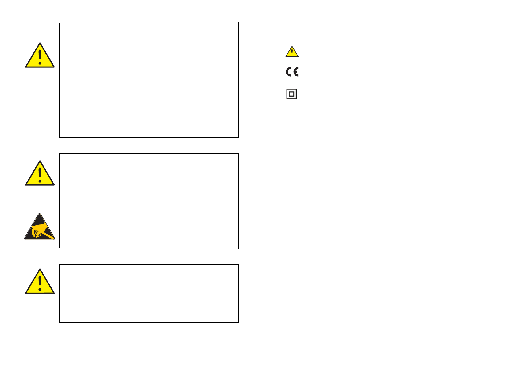
SIGNATURFORKLARING:
Trekant med udråbstegn: Advarsel / krav. Hændelser der kan
føre til livstruende situationer.
CE-mærket er det synlige tegn på modulets overensstemmelse
med direktivernes krav.
Dobbelt isolation er symbolet for, at modulet overholder ekstra
krav til isolation.
SIKKERHEDSREGLER
DEFINITIONER:
Farlige spændinger er defineret som områderne: 75...1500 Volt DC og 50...1000
Volt AC.
Teknikere er kvalificerede personer, som er uddannet eller oplært til at kunne
udføre installation, betjening eller evt. fejlfinding både teknisk og sikkerhedsmæssigt forsvarligt.
Operatører er personer, som under normal drift med produktet skal indstille og
betjene produktets trykknapper eller potentiometre, og som er gjort bekendt
med indholdet af denne manual.
MODTAGELSE OG UDPAKNING:
Udpak modulet uden at beskadige dette, og sørg for, at manualen altid følger
modulet og er tilgængelig. Indpakningen bør følge modulet, indtil dette er monteret på blivende plads.
Kontrollér ved modtagelsen, at modultypen svarer til den bestilte.
MILJØFORHOLD:
Undgå direkte sollys, kraftigt støv eller varme, mekaniske rystelser og stød, og
udsæt ikke modulet for regn eller kraftig fugt. Om nødvendigt skal opvarmning,
udover de opgivne grænser for omgivelsestemperatur, forhindres ved hjælp af
ventilation.
Alle moduler hører til Installationskategori II, Forureningsgrad 1 og Isolationsklasse II.
INSTALLATION:
Modulet må kun tilsluttes af teknikere, som er bekendte med de tekniske
udtryk, advarsler og instruktioner i manualen, og som vil følge disse.
Hvis der er tvivl om modulets rette håndtering, skal der rettes henvendelse til
den lokale forhandler eller alternativt direkte til:
PR electronics A/S, Lerbakken 10,
8410 Rønde, Danmark, tlf: +45 86 37 26 77.
Installation og tilslutning af modulet skal følge landets gældende regler for
installation af elektrisk materiel bl. a. med hensyn til ledningstværsnit, forsikring og placering.
Beskrivelse af indgang / udgang og forsyningsforbindelser findes på blokdiagrammet og sideskiltet.
32
Page 4

For moduler, som er permanent tilsluttet farlig spænding, gælder:
For-sikringens maksimale størrelse er 10 A og skal sammen med en
afbryder placeres let tilgængelig og tæt ved modulet. Afbryderen skal
mærkes således, at der ikke er tvivl om, at den afbryder spændingen til
modulet.
KALIBRERING OG JUSTERING:
Under kalibrering og justering skal måling og tilslutning af eksterne spændinger
udføres i henhold til denne manual, og teknikeren skal benytte sikkerhedsmæssigt korrekte værktøjer og instrumenter.
OVERENSSTEMMELSESERKLÆRING
Som producent erklærer
PR electronics A/S
Lerbakken 10
DK-8410 Rønde
hermed at følgende produkt:
Type: 5222
Navn: Programmerbar I/f konverter
BETJENING UNDER NORMAL DRIFT:
Operatører må kun indstille eller betjene modulerne, når disse er fast installeret
på forsvarlig måde i tavler el. lignende, så betjeningen ikke medfører fare for liv
eller materiel. Dvs., at der ikke er berøringsfare, og at modulet er placeret, så
det er let at betjene.
RENGØRING:
Modulet må, i spændingsløs tilstand, rengøres med en klud let fugtet med
destilleret vand eller sprit.
ANSVAR:
I det omfang, instruktionerne i denne manual ikke er nøje overholdt, vil kunden
ikke kunne rette noget krav, som ellers måtte eksistere i henhold til den indgåede salgsaftale, mod PR electronics A/S.
er i overensstemmelse med følgende direktiver og standarder:
EMC-direktivet 2004/108/EF og senere tilføjelser
EN 61326
Denne erklæring er udgivet i overensstemmelse med EMC-direktivets paragraf
10, stk. 1. For specifikation af det acceptable EMC-niveau henvises til modulets elektriske specifikationer.
Lavspændingsdirektivet 73/23/EØF tilføjelser
EN 61010-1
CE-mærket for overensstemmelse med lavspændingsdirektivet blev tilføjet i
året: 1997
Rønde, 20. dec. 2005 Peter Rasmussen
Producentens underskrift
4
5
Page 5
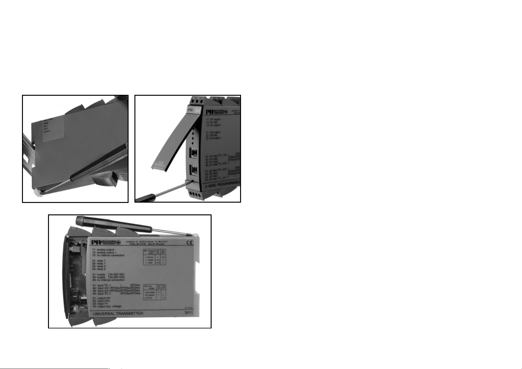
ADSKILLELSE AF SYSTEM 5000
Husk først at demontere tilslutningsklemmerne med farlig spænding.
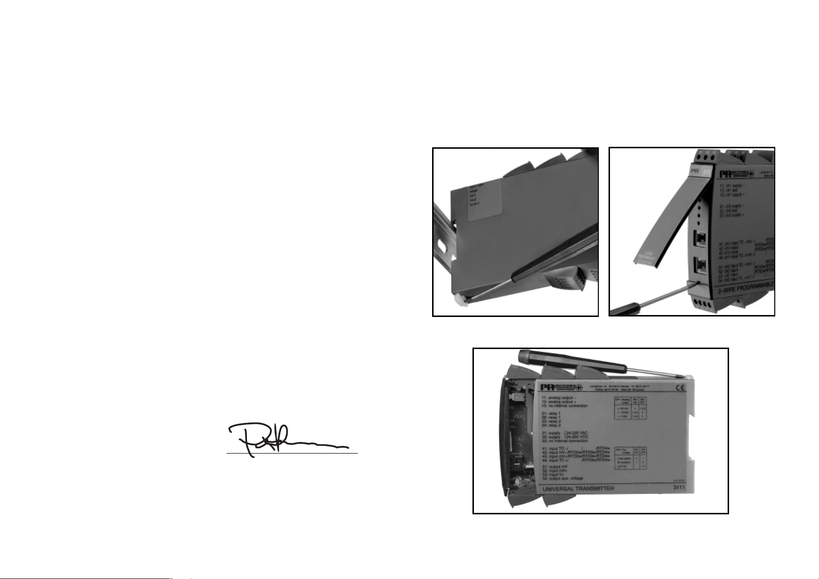
Modulet frigøres fra DIN-skinnen ved at løfte i den nederste lås, som vist på
billede 1.
Printet udtages derefter ved at løfte i den øverste lås og samtidig trække ud i
frontpladen, se billede 2.
Nu kan switche og jumpere ændres.
Programmeringsstikket er tilgængeligt ved at åbne fronten som vist på billede 3.
Billede 1: Frigørelse fra DIN-skinne.
Billede 3: Adgang til programmeringsstik.
PROGRAMMERBAR I/f KONVERTER
5222
• Indgang for TC/RTD, lin. modstand, mV eller mA og V
• Frekvensudgang NPN, PNP, TTL
• Programmerbar via PC
• Galvanisk isoleret 3,75 kVAC
• AC/DC forsynet
• DIN-skinne montering
GENERELT:
PRecon 5222 konverteren konfigureres til den aktuelle opgave ved hjælp af en
standard PC med konfigurationssættet Loop Link. Konverteren kan konfigureres
inden installation eller direkte i processen.
PRecon 5222 kan også leveres færdigkonfigureret efter specifikationer, se konfigurationsindeks i databladet.
INDGANGSTYPER FOR 5222 A1:
RTD-indgang for Pt100/Ni100 i temperaturområder efter IEC 751, DIN 43760. Via
Loop Link kan man måle og udkompensere kabelmodstanden ved 2-leder tilslutning. Automatisk kabelkompensering ved 3- eller 4-leder tilslutning.
Termoelementindgang (TC) for standard termoelementer i temperaturområder
efter IEC 584, DIN 43710 eller ASTM E988-90.
Intern CJC med Pt100 føler i tilslutningsklemme (option - type 5910 og 5913),
ekstern CJC med Pt100/Ni100 i 2-leder tilslutning eller fast CJC (termostatboks).
Modstandsindgang for måling op til 5000 Ω med kabelkompensering ved 3-
eller 4-leder tilslutning.
mV-indgang for DC-spændingssignaler.
FØLER- OG KABELFEJL:
Ved føler- og / eller kabelfejl for TC-, RTD- og modstandsindgang kan udgangen
programmeres til at antage en valgfri fast værdi.
Billede 2: Udtagelse af print.
6
7
Page 6

INDGANGSTYPER FOR 5222 A2:
Strømindgang for signaler op til 100 mADC. Indgangen er beskyttet med en
PTC-modstand.
Spændingsindgang for signaler op til 250 VDC.
ELEKTRISKE SPECIFIKATIONER - TYPE 5222:
Specifikationsområde:
-20°C til +60°C
HJÆLPEFORSYNINGER:
2-trådsforsyning 16...28 VDC / 20 mA til forsyning af 2-trådstransmitter.
Referencespænding 2,5 VDC / 15 mA som reference for 3-leder potentio meter.
UDGANGE:
PNP-, NPN- og TTL-udgangene er galvanisk adskilt fra forsyning og indgang.
Udgangene er strømbegræn sede ved hjælp af PTC-modstande.
Det er muligt at reversere udgangene i forhold til indgangen.
Impulstiden kan vælges frit.
Fra PReset kan der vælges en “LOW CUT OFF” værdi. Dette betyder, at udgangen fastholdes på 0 Hz, når indgangen er under “LOW CUT OFF” værdien.
Reaktionstiden er programmerbar.
NPN- og PNP-udgange for eksternt relæ, elektromekanisk tæller, PLC-indgang
eller til svarende be lastning.
Aktiv udgang etableres ved at forbinde NPN til PNP-udgangen (lus ben 13 - 14).
PNP-udgangen kan afgive impulser på 20 ms til elektromekaniske tællere.
LINEARISERING:
Udgangssignalet er lineariseret til den valgte følerstandard, men det er også
muligt at indlægge kundespecificerede lineariseringer.
OPSÆTNING:
Loop Link indeholder PReset software, adapter, kabel mm.
Adapteren har galvanisk isolation for at beskytte PC´en.
Kommunikation mellem PRecon 5222 og Loop Link er 2-vejs, så konfiguration
med serienummer og TAG-nummer kan hentes ved omkonfigurering eller kontrol.
Fælles specifikationer:
Forsyningsspænding
Version 5222---A- .................................... 19,2...78 VDC
21,6...52,8 VAC
Version 5222---B- .................................... 80...300 VDC
72,8...253 VAC
Frekvens ..................................................... 50...60 Hz
Strømforbrug ............................................. ≤ 2,6 W
Sikring ........................................................ 400 mA T / 250 VAC
Isolation, test / drift .................................... 3,75 kVAC / 250 VAC
Kommunikationsinterface ........................... Loop Link
Reaktionstid (programmerbar)
Version 5222-1-- (temp. vers.) ................ 350 ms...60 s
Version 5222-2-- (mA / V vers.) ............... 200 ms...60 s
Opdateringstid
Version 5222-1-- (temp. vers.) ................ 100 ms
Version 5222-1-- (mA / V vers.) ............... 60 ms
Signaldynamik, indgang ............................. 20 bit
Kalibreringstemperatur ............................... 20...28°C
Temperaturkoefficient ................................. < ±0,01% af span / °C
Linearitetsfejl .............................................. < 0,1% af span
Virkning af forsyningsspændings-
ændring ...................................................... < 0,005% af span / V
Hjælpespændinger type 5222-2:
Referencespænding ................................... 2,5 VDC ±0,5% / 15 mA
2-trådsforsyning ......................................... 28 VDC / 0 mA
16 VDC / 20 mA
EMC-immunitetspåvirkning ........................ < ±0,5%
Ledningskvadrat (max.) .............................. 1 x 2,5 mm
2
flerkoret ledning
Klemskruetilspændingsmoment ................. 0,5 Nm
Relativ luftfugtighed ................................... < 95% RH (ikke kond.)
Mål (HxBxD) ............................................... 109 x 23,5 x 130 mm
DIN-skinne type .......................................... DIN 46277
Tæthedsgrad (kabinet / klemmer) .............. IP50 / IP20
Vægt ........................................................... 250 g
8
9
Page 7
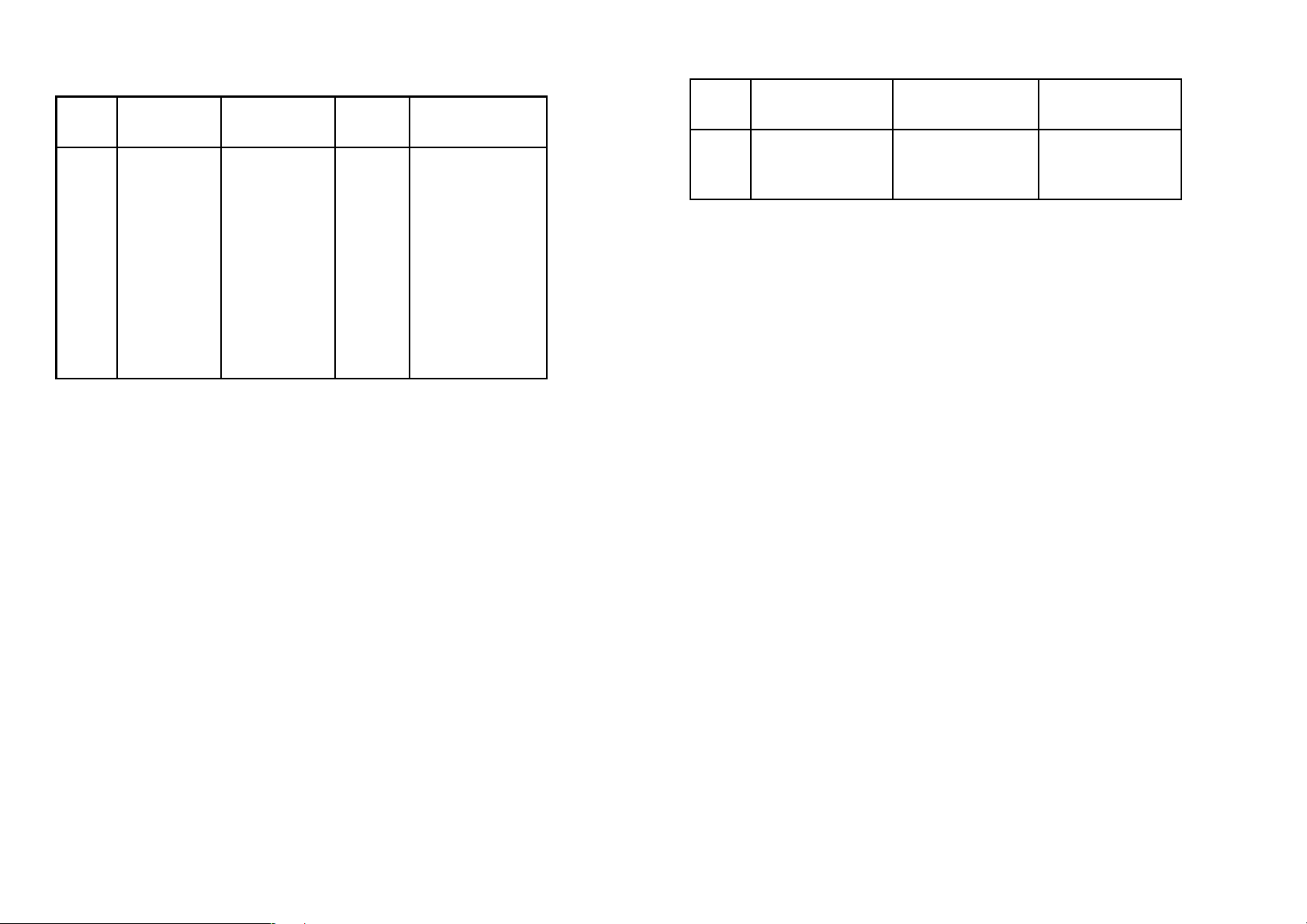
Elektriske specifikationer - INDGANG type 5222-1:
TC-indgang:
Min. Max. Min.
Type temperatur temperatur span Norm
B +400°C +1820°C 200°C IEC584
E -100°C +1000°C 50°C IEC584
J -100°C +1200°C 50°C IEC584
K -180°C +1372°C 50°C IEC584
L -100°C +900°C 50°C DIN43710
N -180°C +1300°C 100°C IEC584
R -50°C +1760°C 200°C IEC584
S -50°C +1760°C 200°C IEC584
T -200°C +400°C 50°C IEC584
U -200°C +600°C 75°C DIN43710
W3 0°C +2300°C 200°C ASTM E988-90
W5 0°C +2300°C 200°C ASTM E988-90
Max. nulpunktsforskydning (offset) ............ 50% af valgt max. værdi
Følerstrøm .................................................. Nom. 100 nA
Primær nøjagtighed:
Type E,J,K,L,N,T,U ...................................... < ±1°C
Type B,R,S,W3,W5 ..................................... < ±2°C
Kompenseringsnøjagtighed (CJC) ............. < ±1°C
Temperaturkoefficient:
Type E,J,K,L,N,T,U
span < 500°C ..................................... ±0,05°C / °C
span > 500°C ..................................... ±0,01% af span / °C
Type B,R,S,W3,W5 ..................................... 0,2°C / °C
Følerfejlsindikering (udgang) ...................... Upscale / downscale
mV-indgang:
Måleområde ............................................... 0...100 mV
Min. måleområde ....................................... 5 mV
Max. nulpunktsforskydning (offset) ............ 50% af valgt max. værdi
Indgangsmodstand .................................... Nom. 10 MΩ
omg.
omg.
omg.
RTD-indgang:
RTD- Min. Max. Min.
type værdi værdi span
Pt100 -200°C +850°C 25°C
Ni100 -60°C +250°C 25°C
Lin.R 0 Ω 5000 Ω 30 Ω
Max. nulpunktsforskydning (offset) ............ 50% af valgt max. værdi
Kabelmodstand pr. leder (max.) ................. 10 Ω
Følerstrøm .................................................. Nom. 0,2 mA
Primær nøjagtighed .................................... < ±0,2°C
Temperaturkoefficient:
span < 100°C ..................................... ±0,01°C/°C
span > 100°C ..................................... ±0,01% af span/°C
Virkning af følerkabelmodstand
(3- / 4-leder) ............................................... < 0,002 Ω/Ω
Følersfejlsindikering (udgang) ..................... Upscale / downscale
Lineær modstandsindgang:
Måleområde ............................................... 0...5000 Ω
Min. måleområde (span) ............................. 30 Ω
Max. nulpunktsforskydning (offset) ............ 50% af valgt max. værdi
Max. kabelmodstand pr. leder ................... 10 Ω
Følerstrøm .................................................. Nom. 0,2 mA
Virkning af følerkabelmodstand
(3- / 4-leder) ............................................... < 0,002 Ω/Ω
Følerfejlsindikering (udgang) ...................... Upscale / downscale
Elektriske specifikationer - INDGANG type 5222-2
Spændingsindgang:
Måleområde ............................................... 0...250 VDC
Min. måleområde (span) ............................. 50 mVDC
Max. nulpunktsforskydning (offset) ............ 50% af valgt max. værdi
Indgangsmodstand ≤ 2,5 VDC ................... Nom. 10 MΩ
> 2,5 VDC .................. Nom. 5 MΩ
omg.
omg.
10
Strømindgang:
Måleområde ............................................... 0...100 mA
Min. måleområde (span) ............................. 4 mA
Max. nulpunktsforskydning (offset) ............ 50% af valgt max. værdi
11
Page 8
Indgangsmodstand:
Forsynet enhed .......................................... Nom. 10 Ω + PTC 10 Ω
Ikke-forsynet enhed ................................... R
Elektriske specifikationer - UDGANGE:
Frekvensområde ......................................... 0,00005...25000 Hz
Min. frekvens (span) ................................... 0,00005 Hz
Duty cycle (0 ... 25000 Hz) ......................... 50%
eller
Programmerbar impulstid (f < 500 Hz) ....... 1...1000 ms
Max. 90% duty cycle
PNP-udgang:
I
max. .................................................... 30 mA
out
I
max. peak ........................................... 170 mA
out
V
min. / max. ......................................... 22 / 26 V
out
C
............................................................ 10 nF
out
R
typ. ..................................................... 25 Ω
out
Elektromekanisk tæller ............................... 24 V / 135 mA / 20 ms
NPN-udgang:
I
max. ................................................... 150 mA
sink
I
max. peak .......................................... 300 mA
sink
Max. indgang ............................................. 55 V
C
............................................................ 10 nF
out
R
typ. ..................................................... 10 Ω
out
SHUNT
= ∞, V
DROP
< 6 V
BESTILLINGSSKEMA:
Type Version Indgang
5222 Standard : A
Bemærk!
Husk at bestille CJC-stik type 5910 i forbindelse med TC-indgange med intern
CJC.
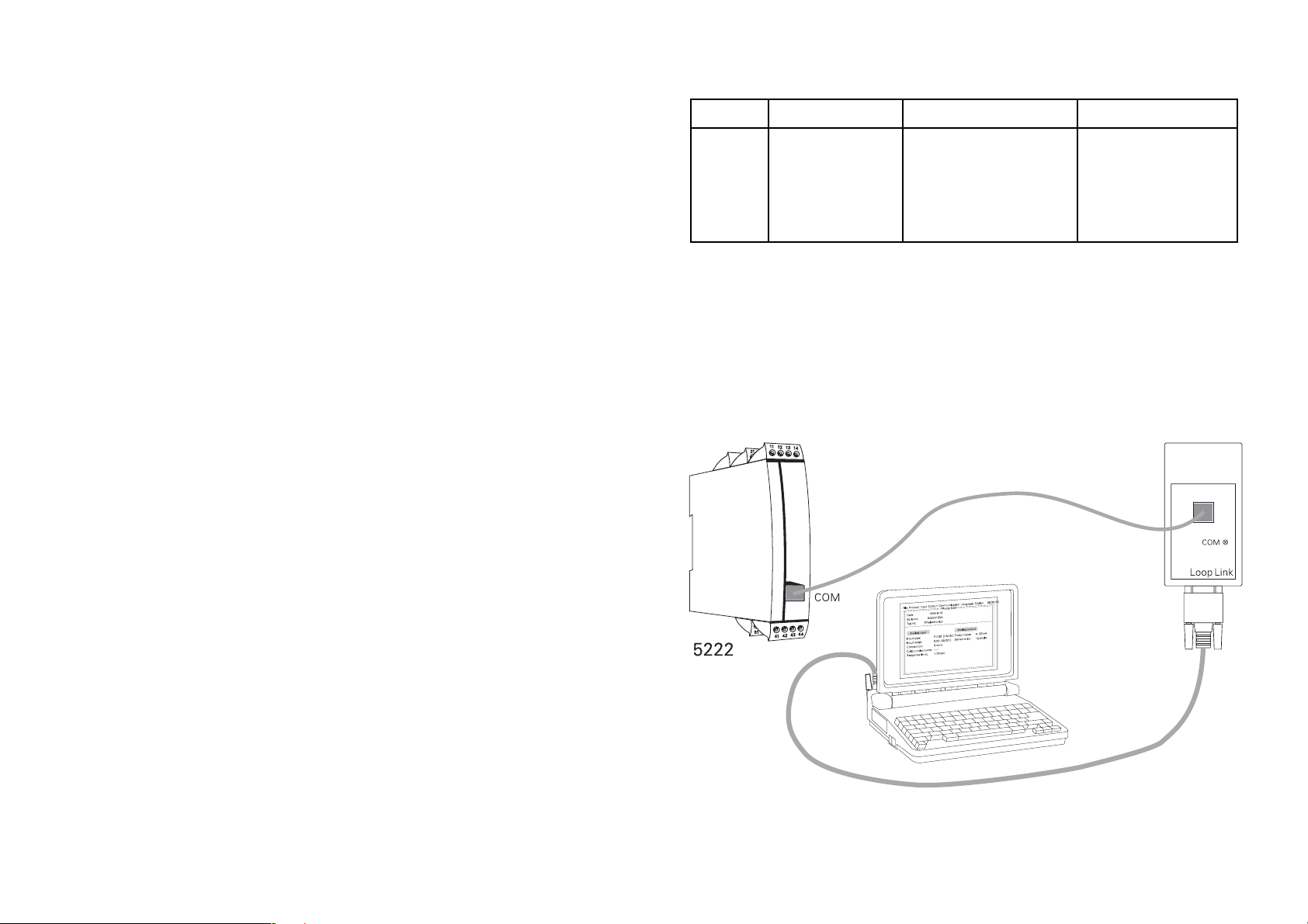
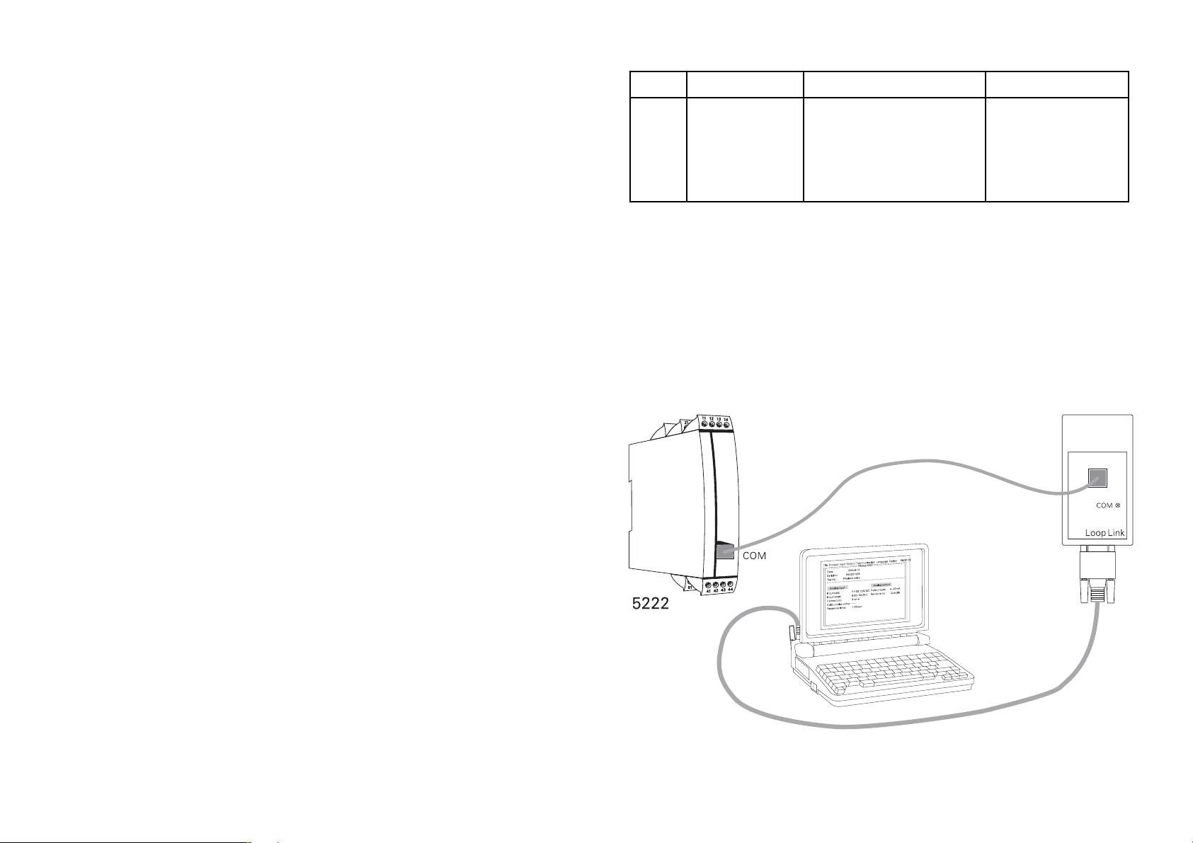
5222 FORBINDELSE TIL LOOP LINK:
RTD / TC / mV / R : 1
mA / V / mV : 2
Forsyning
24...65 VDC / : A
24...48 VAC
100...250 VDC / : B
80...230 VAC
TTL-udgang:
I
sink/source
I
sink/source
V
............................................................ 5 V ±5%
out
C
............................................................ 10 nF
out
R
typ. ..................................................... 55 Ω
out
GOST R godkendelse:
VNIIM .......................................................... Cert. no. Ross DK.ME48.V01899
Overholdte myndighedskrav: Standard:
EMC 2004/108/EF
Emission og immunitet ..................... EN 61326
LVD 73/23/EØF ........................................... EN 61010-1
PELV/SELV .................................................. IEC 364-4-41 og EN 60742
Af span = Af det aktuelt valgte område
min. ........................................ 15 mA
peak ....................................... 100 mA
1312
Page 9
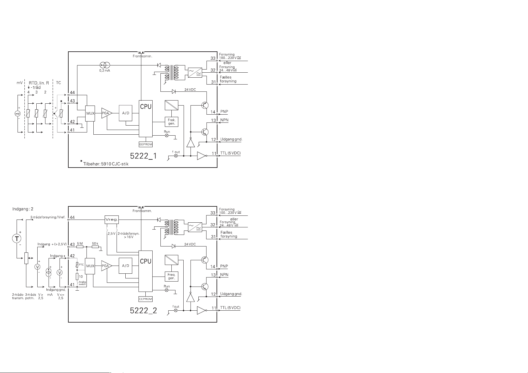
BLOKDIAGRAMMER:
PROGRAMMABLE I/f CONVERTER
PRecon type 5222
TABLE OF CONTENTS
Warnings . . . . . . . . . . . . . . . . . . . . . . . . . . . . . . . . . . . . . . 16
Safety instructions. . . . . . . . . . . . . . . . . . . . . . . . . . . . . . . 18
Declaration of Conformity . . . . . . . . . . . . . . . . . . . . . . . . . 20
How to dismantle SYSTEM 5000 . . . . . . . . . . . . . . . . . . . 21
General . . . . . . . . . . . . . . . . . . . . . . . . . . . . . . . . . . . . . . . 22
Input types for 5222A1 . . . . . . . . . . . . . . . . . . . . . . . . . . . 22
Sensor and cable errors . . . . . . . . . . . . . . . . . . . . . . . . . . 22
Input types for 5222A2 . . . . . . . . . . . . . . . . . . . . . . . . . . . 23
Auxiliary supplies. . . . . . . . . . . . . . . . . . . . . . . . . . . . . . . . 23
Outputs . . . . . . . . . . . . . . . . . . . . . . . . . . . . . . . . . . . . . . . 23
Linearisation . . . . . . . . . . . . . . . . . . . . . . . . . . . . . . . . . . . 23
Set-up . . . . . . . . . . . . . . . . . . . . . . . . . . . . . . . . . . . . . . . . 23
Electrical specifications. . . . . . . . . . . . . . . . . . . . . . . . . . . 24
Order . . . . . . . . . . . . . . . . . . . . . . . . . . . . . . . . . . . . . . . . . 28
5222 connection to Loop Link . . . . . . . . . . . . . . . . . . . . . 28
Block diagrams . . . . . . . . . . . . . . . . . . . . . . . . . . . . . . . . . 29
14
15
Page 10
GENERAL
HAZARD-
OUS
VOLT AGE
WARNING!
This module is designed for connection to hazardous electric
voltages.
Ignoring this warning can result in severe personal injury or
mechanical damage.
To avoid the risk of electric shock and fire, the safety instructions of this manual must be observed and the guidelines
fol lowed. The specifications must not be exceeded, and the
module must only be applied as described in the following.
Prior to the commissioning of the module, this manual must be
examined carefully.
Only qualified personnel (technicians) should install this module.
If the equipment is used in a manner not specified by the
manufacturer, the protection provided by the equipment may be
impaired.
WARNING!
Until the module is fixed, do not connect hazardous voltages to
the module.
The following operations should only be carried out on a disconnected module and under ESD safe conditions:
Dismantlement of the module for setting of dipswitches and
jumpers.
General mounting, connection and disconnection of wires.
Troubleshooting the module.
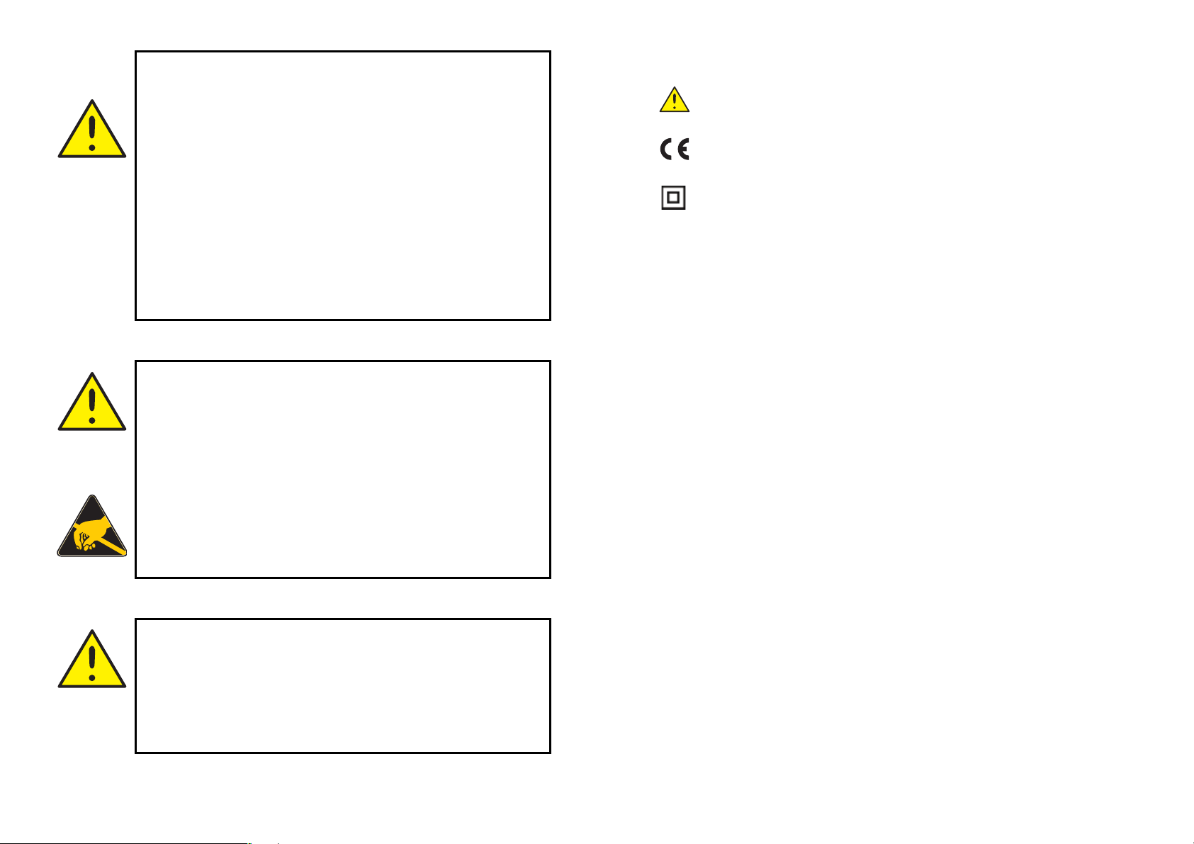
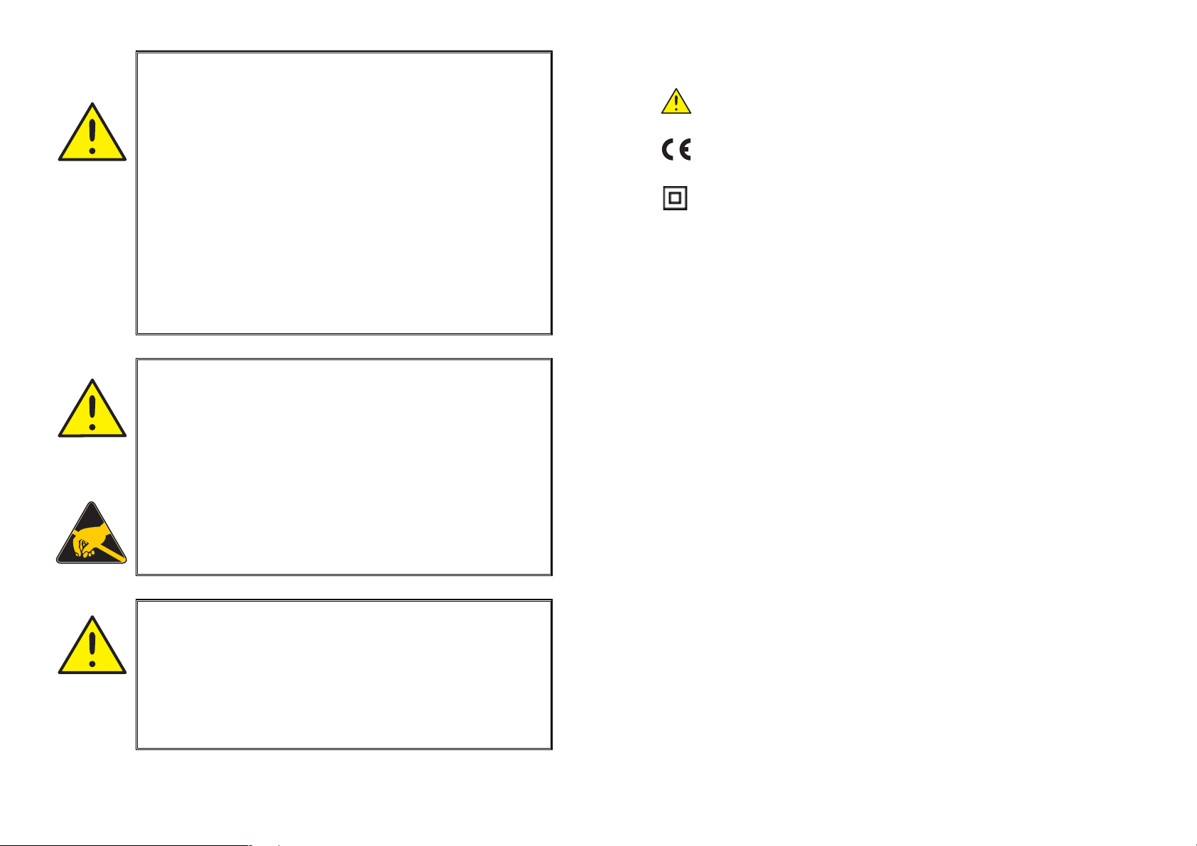
SYMBOL IDENTIFICATION
Triangle with an exclamation mark: Warning / demand.
Potentially lethal situations.
The CE mark proves the compliance of the module with
the essential requirements of the directives.
The double insulation symbol shows that the module
is protected by double or reinforced insulation.
INSTAL-
LATION
Repair of the module and replacement of circuit breakers
must be done by PR electronics A/S only.
WARNING!
SYSTEM 5000 must be mounted on DIN rail according to DIN
46277.
The communication connector of SYSTEM 5000 is connected
to the input terminals on which dangerous voltages can occur,
and it must only be connected to the programming unit Loop
Link by way of the enclosed cable.
1716
Page 11

SAFETY INSTRUCTIONS
DEFINITIONS:
Hazardous voltages have been defined as the ranges: 75 to 1500 Volt DC, and
50 to 1000 Volt AC.
Technicians are qualified persons educated or trained to mount, operate, and
also troubleshoot technically correct and in accordance with safety regulations.
Operators, being familiar with the contents of this manual, adjust and operate
the knobs or potentiometers during normal operation.
RECEIPT AND UNPACKING:
Unpack the module without damaging it and make sure that the manual always
follows the module and is always available. The packing should always follow
the module until this has been permanently mounted.
Check at the receipt of the module whether the type corresponds to the one
ordered.
The following apply to fixed hazardous voltages-connected modules:
The max. size of the protective fuse is 10 A and, together with a power
switch, it should be easily accessible and close to the module. The
power switch should be marked with a label telling it will switch off the
voltage to the module.
CALIBRATION AND ADJUSTMENT:
During calibration and adjustment, the measuring and connection of external
voltages must be carried out according to the specifications of this manual.
The technician must use tools and instruments that are safe to use.
NORMAL OPERATION:
Operators are only allowed to adjust and operate modules that are safely fixed
in panels, etc., thus avoiding the danger of personal injury and damage. This
means there is no electrical shock hazard, and the module is easily accessible.
ENVIRONMENT:
Avoid direct sunlight, dust, high temperatures, mechanical vibrations and shock,
as well as rain and heavy moisture. If necessary, heating in excess of the stated
limits for ambient temperatures should be avoided by way of ventilation.
All modules fall under Installation Category II, Pollution Degree 1, and Insulation
Class II.
MOUNTING:
Only technicians who are familiar with the technical terms, warnings, and
instructions in the manual and who are able to follow these should connect the
module.
Should there be any doubt as to the correct handling of the module, please
contact your local distributor or, alternatively,
PR electronics A/S, Lerbakken 10, DK-8410 Rønde, Denmark,
tel: +45 86 37 26 77.
Mounting and connection of the module should comply with national legislation
for mounting of electric materials, i.a. wire cross section, protective fuse, and
location. Descriptions of input / output and supply connections are shown in
the block diagram and side label.
CLEANING:
When disconnected, the module may be cleaned with a cloth moistened with
distilled water or ethyl alcohol.
LIABILITY:
To the extent the instructions in this manual are not strictly observed, the
custom er cannot advance a demand against PR electronics A/S that would
otherwise exist according to the concluded sales agreement.
18
19
Page 12
DECLARATION OF CONFORMITY
HOW TO DISMANTLE SYSTEM 5000
As manufacturer
PR electronics A/S
Lerbakken 10
DK-8410 Rønde
hereby declares that the following product:
Type: 5222
Name: Programmable I/f converter
is in conformity with the following directives and standards:
EMC directive 2004/108/EC and later amendments
EN 61326
This declaration is issued in compliance with article 10, subclause 1 of the EMC
directive. For specification of the acceptable EMC performance level, refer to
the electrical specifications for the module.
The Low Voltage directive 73/23/EEC and later amendments
EN 61010-1
The CE mark for compliance with the Low Voltage directive was affixed in the
year: 1997
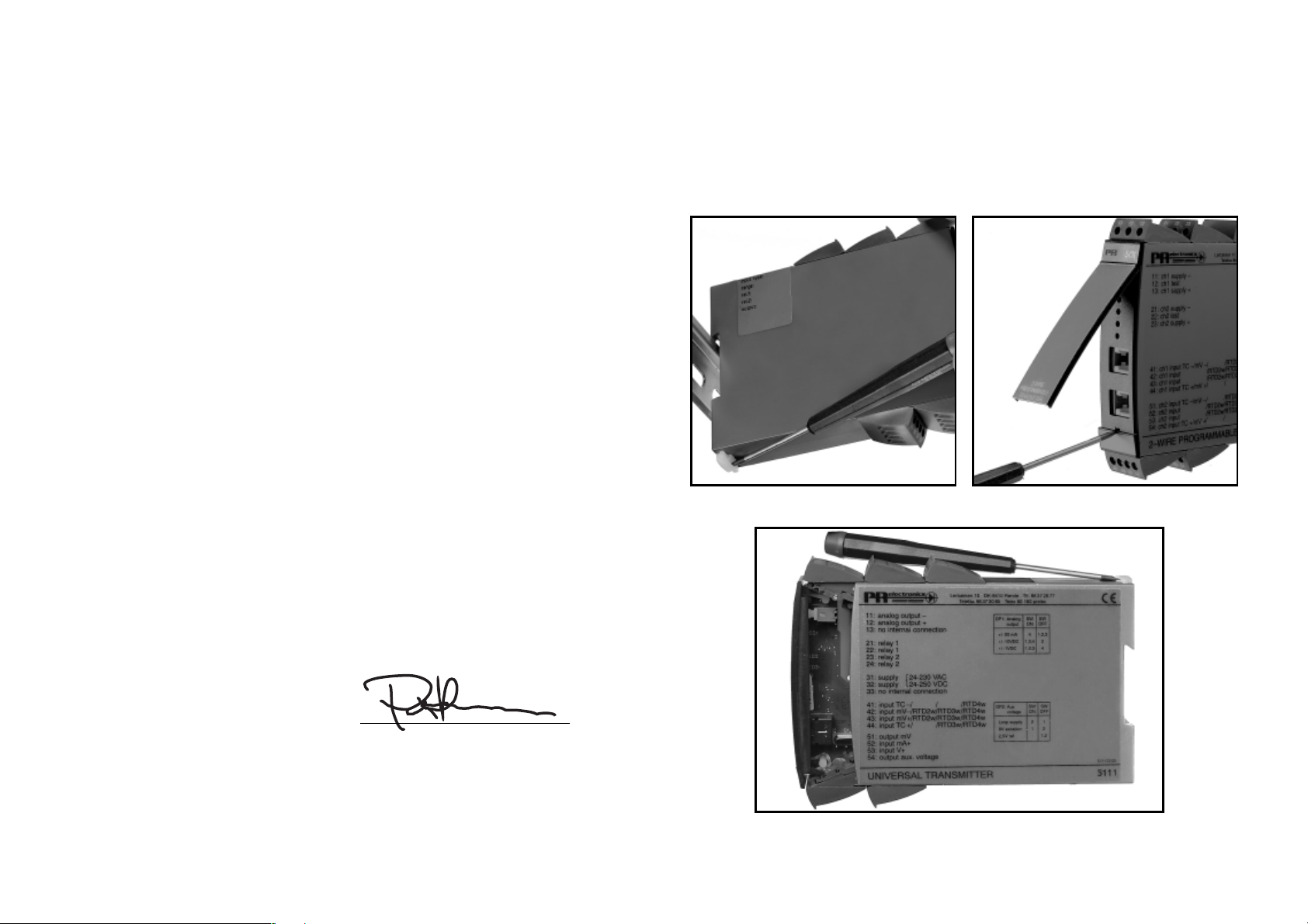
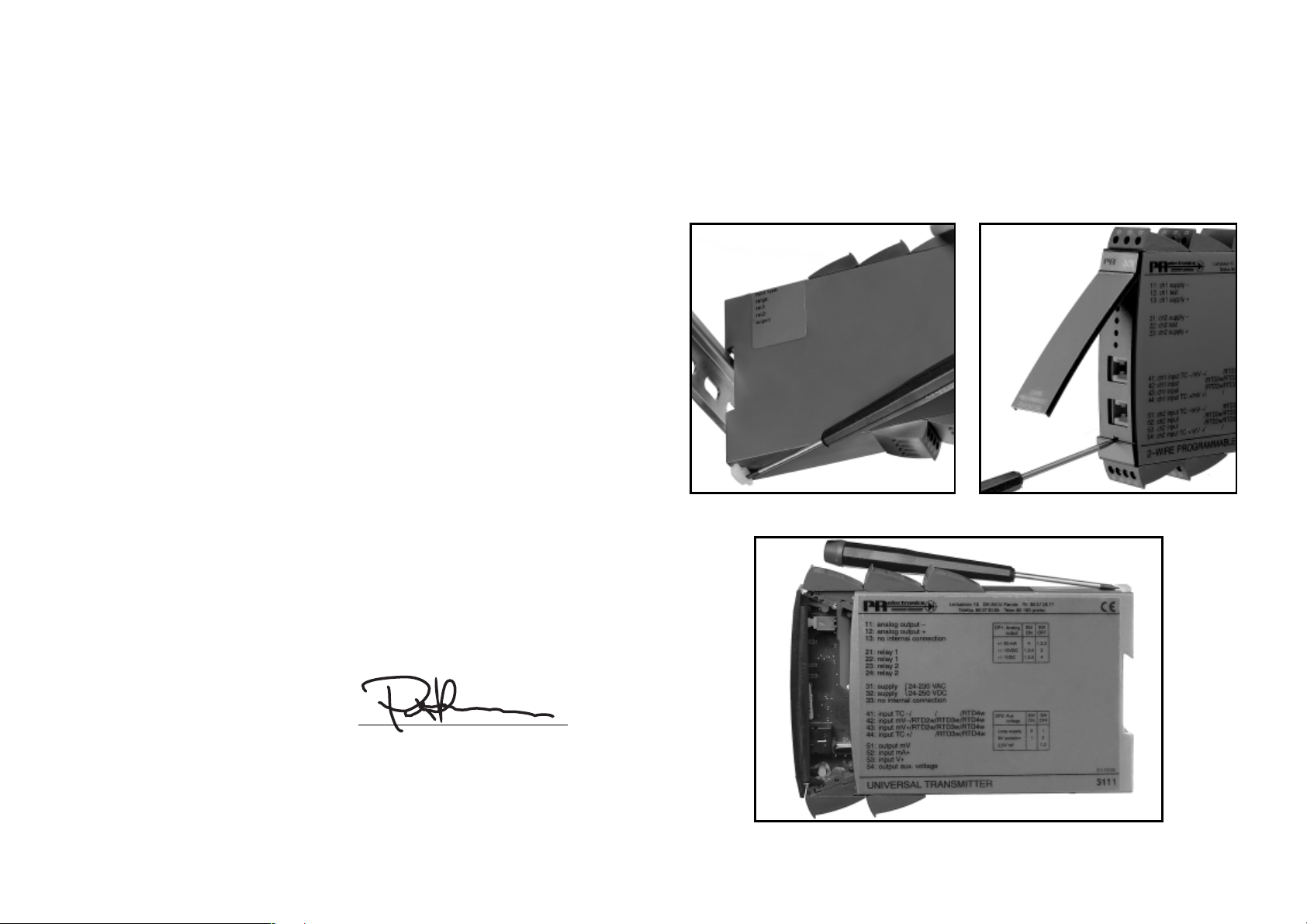
First, remember to demount the connectors with hazardous voltages. By lifting
the bottom lock, the module is detached from the DIN rail as shown in picture 1.
Then, by lifting the upper lock and pulling the front plate simultaneously the
PCB is removed as shown in picture 2.
Switches and jumpers can now be adjusted. By opening the front, the programming connector is accessible as shown in picture 3.
Picture 1: Separation from DIN rail.
Picture 3: Access to programming
connector.
Rønde, 20 Dec. 2005 Peter Rasmussen
Manufacturer’s signature
Picture 2: Removal of PCB.
2120
Page 13

PROGRAMMABLE I/f CONVERTER
5222
• Input for TC/RTD, lin. resistance, mV or mA and V
• Frequency output NPN, PNP, TTL
• Programmable from PC
• Galvanically isolated 3.75 kVAC
• AC/DC-supplied
• DIN rail mounting
GENERAL:
The PRecon 5222 converter is configured to the actual application by means
of a standard PC using the configuration kit Loop Link. The converter may be
configured prior to installation or directly in the process.
The PRecon 5222 may be ordered configured from factory according to your
specification, see options index in the data sheet.
INPUT TYPES FOR 5222 A1:
RTD input for Pt100/Ni100 in temperature ranges acc. to IEC 751 and DIN 43760.
By way of Loop Link, the cable resistance can be measured and compensated
on a 2-wire connection.
Automatic cable compensation on 3- or 4-wire connection.
Thermocouple input (TC) for standard thermocouples in temperature ranges
acc. to IEC 584, DIN 43710, or ASTM E988-90.
Internal CJC with Pt100 sensor in the connector (optional - type 5910 and 5913),
external CJC with Pt100/Ni100 on 2-wire connection, or fixed CJC (thermostat
box).
Resistance input for ohmic resistance measurement, max. range 5000 Ω.
Automatic cable compensation on 3- or 4-wire connection.
mV input for DC voltage signals.
SENSOR AND CABLE ERRORS:
At sensor and / or cable errors for TC, RTD, and resistance inputs, the output can
be programmed to adopt a programmable value.
INPUT TYPES FOR 5222 A2:
Current input for signals of max. 100 mADC. The input is protected by a PTC
resistor.
Voltage input for signals of max. 250 VDC.
AUXILIARY SUPPLIES:
Loop supply 16...28 VDC / 20 mA for supply of loop-powered transmitter.
Reference voltage 2.5 VDC / 15 mA as reference for 3-wire potentiometer.
OUTPUTS:
The PNP, NPN and TTL outputs are galvanically separated from supply and
input.
The outputs are current-limited by way of PTC resistors.
It is possible to reverse the output in relation to input.
Pulse time is programmable.
From PReset a “LOW CUT OFF” value can be selected, which means that the
output is fixed to 0 Hz, when the input is below the “LOW CUT OFF” value.
Response time is programmable.
NPN and PNP outputs for external relay, electromechanical counter, PLC input,
or equivalent load.
Active output is established by connecting the NPN to the PNP output (jumper
pins 13-14).
The PNP output can emit pulses of 20 ms to electromechanical counters.
LINEARISATION:
The output signal is linearised acc. to the selected sensor type, but customerspecific linearisations are also possible.
SET-UP:
Loop Link contains PReset software, adapter box, cable, etc.
The adapter has galvanic isolation to protect the PC.
Communication between the PRecon 5222 and Loop Link is fully two-way,
meaning that the set-up parameters and series / TAG numbers can be retrieved
from any PRecon for control and reconfiguration.
22
23
Page 14
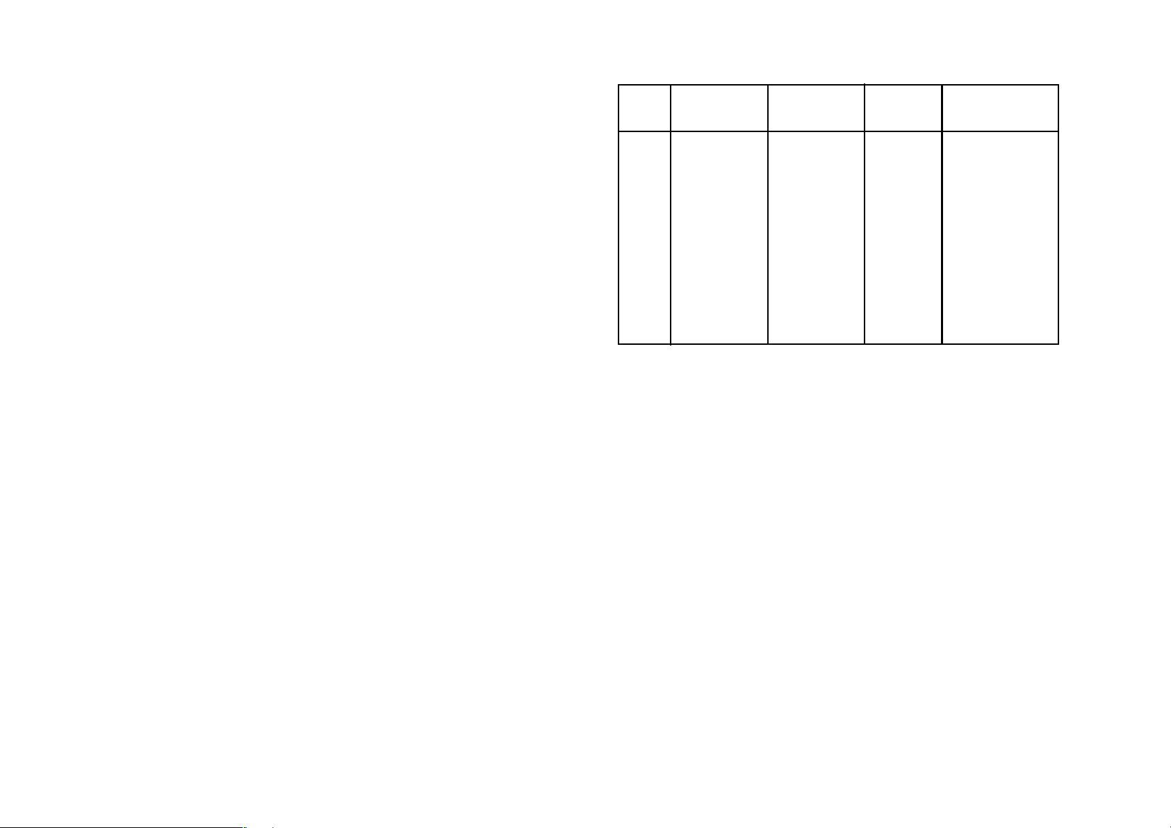
ELECTRICAL SPECIFICATIONS - TYPE 5222:
Specifications range:
-20°C to +60°C
Electrical specifications - INPUT type 5222-1:
TC input:
Min. Max. Min.
Type temperature temperature span Norm
Common specifications:
Supply voltage
Version 5222---A- .................................... 19.2...78 VDC
21.6...52.8 VAC
Version 5222---B- .................................... 80...300 VDC
72.8...253 VAC
Frequency ................................................... 50...60 Hz
Current consumption ................................ ≤ 2.6 W
Fuse ............................................................ 400 mA SB / 250 VAC
Isolation, test /operation ............................ 3.75 kVAC / 250 VAC
Communications interface ......................... Loop Link
Response time (programmable):
Version 5222-1-- (temp. vers.) ................ 350 ms...60 s
Version 5222-2-- (mA / V vers.) ............... 200 ms...60 s
Updating time:
Version 5222-1-- (temp. vers.) ................ 100 ms
Version 5222-1-- (mA / V vers.) ............... 60 ms
Signal dynamics, input ............................... 20 bit
Calibration temperature ............................. 20...28°C
Temperature coefficient .............................. < ±0.01% of span / °C
Linearity error ............................................. < 0.1% of span
Effect of supply voltage change ................ < 0.005% of span / V
Auxiliary voltages type 5222-2:
Reference voltage ...................................... 2.5 VDC ±0.5% / 15 mA
Loop supply ............................................... 28 VDC / 0 mA
16 VDC / 20 mA
EMC immunity influence ............................ < ±0.5%
2
Wire size (max.) .......................................... 1 x 2.5 mm
Screw terminal torque ................................ 0.5 Nm
Relative air humidity ................................... < 95% RH (non-cond.)
Dimensions (HxWxD) .................................. 109 x 23.5 x 130 mm
DIN rail type ................................................ DIN 46277
Tightness (enclosure / terminals) ............... IP50 / IP20
Weight ........................................................ 250 g
stranded wire
B +400°C +1820°C 200°C IEC584
E -100°C +1000°C 50°C IEC584
J -100°C +1200°C 50°C IEC584
K -180°C +1372°C 50°C IEC584
L -100°C +900°C 50°C DIN43710
N -180°C +1300°C 100°C IEC584
R -50°C +1760°C 200°C IEC584
S -50°C +1760°C 200°C IEC584
T -200°C +400°C 50°C IEC584
U -200°C +600°C 750°C DIN43710
W3 0°C +2300°C 200°C ASTM E988-90
W5 0°C +2300°C 200°C ASTM E988-90
Max. offset ................................................. 50% of selected max. value
Sensor current ............................................ Nom. 100 nA
Basic accuracy:
Type E,J,K,L,N,T,U ...................................... < ±1°C
Type B,R,S,W3,W5 ..................................... < ±2°C
Compensation accuracy (CJC) .................. < ±1°C
Temperature coefficient:
Type E,J,K,L,N,T,U
span < 500°C ..................................... ±0.05°C / °C
span > 500°C ..................................... ±0.01% of span / °C
Type B,R,S,W3,W5 ..................................... 0.2°C / °C
Sensor error indication (output) ................. Upscale / downscale
mV input:
Measurement range ................................... 0...100 mV
Min. measurement range ........................... 5 mV
Max. offset ................................................. 50% of selected max. value
Input resistance .......................................... Nom. 10 MΩ
amb.
amb.
amb.
24
25
Page 15

RTD input:
RTD Min. Max. Min.
type value value span
Pt100 -200°C +850°C 25°C
Ni100 -60°C +250°C 25°C
Lin.R 0 Ω 5000 Ω 30 Ω
Max. offset ................................................. 50% of selected max. value
Cable resistance per wire (max.) ................ 10 Ω
Sensor current ............................................ Nom. 0.2 mA
Basic accuracy ........................................... < ±0.2°C
Temperature coefficient:
span < 100°C ..................................... ±0.01°C/°C
span > 100°C ..................................... ±0.01% of span/°C
Effect of sensor cable resistance
(3- / 4-wire) ................................................. < 0.002 Ω/Ω
Sensor error indication (output) ................. Upscale / downscale
amb.
amb.
Input resistance:
Supplied unit .............................................. Nom. 10 Ω + PTC 10 Ω
Non-supplied unit ....................................... R
Electrical specifications - OUTPUTS:
Frequency range ........................................ 0.00005...25000 Hz
Min. frequency (span) ................................. 0.00005 Hz
Duty cycle (0 ... 25000 Hz) ......................... 50%
or
Program. pulse width (f < 500 Hz) ............. 1...1000 ms
Max. 90% duty cycle
PNP output:
I
max. .................................................... 30 mA
out
I
max. peak ........................................... 170 mA
out
V
min. / max. ......................................... 22 / 26 V
out
C
............................................................ 10 nF
out
R
typ. ..................................................... 25 Ω
out
Electromechanical counter ......................... 24 V / 135 mA / 20 ms
SHUNT
= ∞, V
DROP
< 6 V
Linear resistance input:
Measurement range ................................... 0...5000 Ω
Min. measurement range (span) ............... 30 Ω
Max. offset ................................................. 50% of selected max. value
Max. cable resistance per wire .................. 10 Ω
Sensor current ............................................ Nom. 0.2 mA
Effect of sensor cable resistance
(3- / 4-wire) ................................................. < 0.002 Ω/Ω
Sensor error indication (output) ................. Upscale / downscale
Electrical specifications - INPUT type 5222-2
Voltage input:
Measurement range ................................... 0...250 VDC
Min. measurement range (span) ................ 50 mVDC
Max. offset ................................................. 50% of selected max. value
Input resistance ≤ 2.5 VDC ........................ Nom. 10 MΩ
> 2.5 VDC ........................ Nom. 5 MΩ
Current input:
Measurement range ................................... 0...100 mA
Min. measurement range (span) ................ 4 mA
Max. offset ................................................. 50% of selected max. value
26
NPN output:
I
max. ................................................... 150 mA
sink
I
max. peak .......................................... 300 mA
sink
Max. input .................................................. 55 V
C
............................................................ 10 nF
out
R
typ. ..................................................... 10 Ω
out
TTL output:
I
sink/source
I
sink/source
Vout. ........................................................... 5 V ±5%
C
............................................................ 10 nF
out
R
typ. ..................................................... 55 Ω
out
GOST R approval:
VNIIM .......................................................... Cert. no. Ross DK.ME48.V01899
Observed authority requirements: Standard:
EMC 2004/108/EC
Emission and immunity ...................... EN 61326
LVD 73/23/EEC ........................................... EN 61010-1
PELV/SELV .................................................. IEC 364-4-41 and EN 60742
Of span = Of the presently selected range
min. ........................................ 15 mA
peak ....................................... 100 mA
27
Page 16
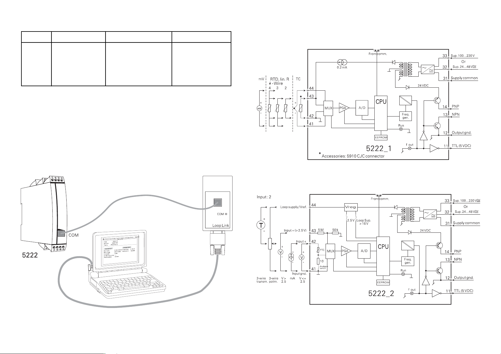
BLOCK DIAGRAMS:ORDER:
Type Version Input
5222 Standard : A
Note!
For TC inputs with internal CJC, remember to order the CJC connector type
5910.
5222 CONNECTION TO LOOP LINK:
RTD / TC / mV / R : 1
mA / V / mV : 2
24...65 VDC / : A
24...48 VAC
100...250 VDC / : B
80...230 VAC
Supply
2928
Page 17

CONVERTISSEUR PROGRAMMABLE I/f
PRecon 5222
SOMMAIRE
Avertissements . . . . . . . . . . . . . . . . . . . . . . . . . . . . . . . . . 32
Consignes de sécurité. . . . . . . . . . . . . . . . . . . . . . . . . . . . 34
Déclaration de conformité. . . . . . . . . . . . . . . . . . . . . . . . . 36
Démontage du SYSTEME 5000 . . . . . . . . . . . . . . . . . . . . 37
Généralités . . . . . . . . . . . . . . . . . . . . . . . . . . . . . . . . . . . . 38
Types d’entrées pour 5222-A1 . . . . . . . . . . . . . . . . . . . . . 38
Défaut capteur et rupture de câble . . . . . . . . . . . . . . . . . . 39
Types d’entrées pour 5222-A2 . . . . . . . . . . . . . . . . . . . . . 39
Alimentations auxiliaires . . . . . . . . . . . . . . . . . . . . . . . . . . 39
Sorties . . . . . . . . . . . . . . . . . . . . . . . . . . . . . . . . . . . . . . . . 39
Linéarisation . . . . . . . . . . . . . . . . . . . . . . . . . . . . . . . . . . . 40
Configuration. . . . . . . . . . . . . . . . . . . . . . . . . . . . . . . . . . . 40
Spécifications électriques . . . . . . . . . . . . . . . . . . . . . . . . . 41
Référence de commande . . . . . . . . . . . . . . . . . . . . . . . . . 45
Connexion entre le PR-5222 et le kit de programmation 45
Schémas de principe . . . . . . . . . . . . . . . . . . . . . . . . . . . . 46
30
31
Page 18
INFOR-
MATIONS
GENERALES
TENSION
DANGE-
REUSE
AVERTISSEMENT !
Ce module est conçu pour supporter une connexion à des tensions électriques dangereuses. Si vous ne tenez pas compte de
cet avertissement, cela peut causer des dommages corporels
ou des dégâts mécaniques.
Pour éviter les risques d’électrocution et d’incendie, conformezvous aux consignes de sécurité et suivez les instructions mentionnées dans ce guide. Vous devez vous limiter aux spécifications indiquées et respecter les instruc tions d’utilisation de ce
module, telles qu’elles sont décrites dans ce guide.
Il est nécessaire de lire ce guide attentivement avant de mettre
ce module en marche. L’installation de ce module est réservée
à un personnel qualifié (techniciens). Si la méthode d’utilisation
de l’équipement diffère de celle décrite par le fabricant, la
protec tion assurée par l’équipe ment risque d’être altérée.
AVERTISSEMENT !
Tant que le module n’est pas fixé, ne le mettez par sous tensions dangereuses. Les opérations suivantes doivent être effectuées avec le module débranché et dans un environnement
ex empt de décharges électrostatiques (ESD) : démontage du
mo dule pour régler les commutateurs DIP et les cavaliers,
montage général, raccordement et débranchement de fils et
re cherche de pannes sur le module.
SIGNIFICATION DES SYMBOLES
Triangle avec point d’exclamation : Attention ! Si vous ne
respectez pas les instructions, la situation pourrait être fatale.
Le signe CE indique que le module est conforme aux exigences
des directives.
Ce symbole indique que le module est protégé par une isolation
double ou renforcée.
INSTAL-
LATION
Seule PR electronics SARL est autorisée à réparer le module
et à remplacer les dis joncteurs.
AVERTISSEMENT !
Il convient de monter l’appareil SYSTEM 5000 sur un rail DIN
en se conformant à la norme DIN 46277. Le connecteur de
communication du SYSTEM 5000 est relié aux borniers d’entrée
sur les quelles peuvent se produire des tensions dangereuses.
Ce connecteur doit uniquement être raccordé à l’appareil de
programmation Loop Link au moyen du câble blindé.
3332
Page 19

CONSIGNES DE SECURITE
DEFINITIONS
Les gammes de tensions dangereuses sont les suivantes : de 75 à 1500 Vcc
et de 50 à 1000 Vca. Les techniciens sont des person nes qualifiées qui sont
capa bles de monter et de faire fonc tionner un appareil, et d’y rechercher les
pannes, tout en respectant les règles de sécurité. Les opérateurs, connaissant
le contenu de ce guide, règlent et actionnent les boutons ou les potentiomètres
au cours des manipulations ordinaires.
Le montage et le raccordement du module doivent être conformes à la législation nationale en vigueur pour le montage de matéri aux électriques, par exemple,
diamètres des fils, fusibles de protection et implantation des modules. Les connexions des alimentations et des entrées / sorties sont décrites dans le schéma
de principe et sur l’étiquette de la face latérale du module.
Les instructions suivantes s’appliquent aux modules fixes connectés en tensions dangereu ses :
Le fusible de protection doit être de 10 A au maximum. Ce dernier,
ainsi que l’interrupteur général, doivent être facilement accessibles et
à proximité du module. Il est recommandé de placer sur l’interupteur
général une étiquette indiquant que ce dernier mettra le module hors
tension.
RECEPTION ET DEBALLAGE
Déballez le module sans l’endommager. Le guide doit toujours être disponible
et se trouver à proximité du module. De même, il est recommandé de conserver
l’emballage du module tant que ce dernier n’est pas définitivement monté. A
la réception du module, vérifiez que le type de module reçu correspond à celui
que vous avez commandé.
ENVIRONNEMENT
N’exposez pas votre module aux rayons directs du soleil et choisissez un
endroit à humidité modérée et à l’abri de la poussière, des températures élevées,
des chocs et des vibrations mécaniques et de la pluie. Le cas échéant, des
systèmes de ventilation permettent d’éviter qu’une pièce soit chauffée au-delà
des limites prescrites pour les températures ambiantes.
Tous les modules appartiennent à la catégorie d’installation Il, au degré de pollution I et à la classe d’isolation Il.
MONTAGE
Il est conseillé de réserver le raccordement du module aux techniciens qui connaissent les termes techniques, les avertis sements et les instructions de ce
guide et qui sont capables d’appliquer ces dernières.
Si vous avez un doute quelconque quant à la manipulation du module, veuillez
contacter votre distributeur local. Vous pouvez également vous adresser à PR
electronics SARL, Zac du Chêne, Activillage, 2, allée des Sorbiers, F-69500
Bron (tél. : (0) 472 140 607) ou à PR electronics A/S, Lerbakken 10, DK-8410
Rønde, Danemark (tél. : +45 86 37 26 77).
ETALONNAGE ET REGLAGE
Lors des opérations d’étalonnage et de réglage, il convient d’effectuer les
mesures et les connexions des tensions externes en respectant les spécifications mentionnées dans ce guide.
Les techniciens doivent utiliser des outils et des instruments pouvant être manipulés en toute sécurité.
MANIPULATIONS ORDINAIRES
Les opérateurs sont uniquement autorisés à régler et faire fonctionner des
modules qui sont solidement fixés sur des platines des tableaux, ect., afin
d’écarter les risques de dommages corporels. Autrement dit, il ne doit exister
aucun danger d’électrocution et le module doit être facilement accessible.
MAINTENANCE ET ENTRETIEN
Une fois le module hors tension, prenez un chiffon humecté d’eau distillée ou
d’alcool éthylique pour le nettoyer.
LIMITATION DE RESPONSABILITE
Dans la mesure où les instructions de ce guide ne sont pas strictement respectées par le client, ce dernier n’est pas en droit de faire une réclamation auprès
de PR electronics SARL, même si cette dernière figure dans l’accord de vente
conclu.
34
35
Page 20
DECLARATION DE CONFORMITE
DEMONTAGE DU SYSTEME 5000
En tant que fabricant
PR electronics A/S
Lerbakken 10
DK-8410 Rønde
déclare que le produit suivant :
Type : 5222
Nom : Convertisseur programmable I/f
correspond aux directives et normes suivantes :
La directive CEM (EMC) 2004/108/CE et les modifications subséquentes
EN 61326
Cette déclaration est délivrée en correspondance à l’article 10, alinéa 1 de la
directive CEM. Pour une spécification du niveau de rendement acceptable
CEM (EMC) renvoyer aux spécifications électriques du module.
La directive basse tension 73/23/CEE et les modifications subséquentes
EN 61010-1
La marque CE pour conformité avec la directive basse tension a été apposée
en 1997
Tout d’abord, n’oubliez pas de démonter les connecteurs où règnent des tensions dangereuses. Débloquez le verrou inférieur pour dégager le module du
rail DIN (voir figure 1). Puis, débloquez le verrou supérieur tout en extrayant la
plaque avant : la carte à circuits imprimés est alors dégagée (voir figure 2).
Vous pouvez maintenant régler les commutateurs et les cavaliers.
En ouvrant la plaque avant, vous pouvez accéder au connecteur de programmation (voir figure 3).
Figure 1 : Séparation du module et
du rail DIN.
Figure 3 : Accès au connecteur de
programmation.
Rønde, le 20 décembre 2005 Peter Rasmussen
Signature du fabricant
Figure 2 : Extraction de la carte à circuits imprimés.
3736
Page 21

CONVERTISSEUR PROGRAMMABLE I/f
5222
• Entrée température ou tension et courant
• Sortie fréquence NPN, PNP ou TTL
• Programmable depuis un PC
• Isolation galvanique 3,75 kVca
• Alimentation Vca/Vcc
• Montage sur rail DIN
GENERALITES :
Le convertisseur PRecon 5222 peut être configuré en fonction d’une application
souhaitée à partir d’un PC, à l’aide du kit de programmation Loop Link. Cette
configuration peut être éffectuée avant ou aprés l’installation.
Le convertisseur PRecon 5222 peut également être livré dans la configuration
requise définie par l’utilisateur, voir l’index de programmation 5222 dans la fiche
technique.
Entrée mV : pour des signaux de tension continue dans une gamme com prise
entre 0 et 100 mV, avec une plage minimale de 5 mV.
DEFAUT CAPTEUR ET RUPTURE DE CABLE :
La sortie est programmable à une valeur fixe lors d’un défaut capteur ou rupture
de cable à l’entrée.
TYPES D’ENTREES POUR 5222-A2 :
Entrée courant programmable dans une gamme comprise entre 0 et 100 mA
continu avec une plage minimale de 5 mA. L’entrée est protegée par une thermistance CTP.
Entrée tension programmable dans une gamme comprise entre 0 mV et 250
Vcc, avec une plage minimale de 50 mV.
ALIMENTATIONS AUXILIAIRES :
(A sélectionner lors de la configuration)
Alimentation de boucle : 16...28 Vcc / 20 mA pour l’alimentation d’un transmetteur 2-fils.
TYPES D’ENTREES POUR 5222-A1 :
Entrée thermocouple (TC) pour les thermocouples standard avec des plages de
température conformes aux normes IEC 584, DIN 43710 et ASTM E988-90.
La Compensation de Soudure Froide (CSF) est réalisée soit par une sonde Pt100
incorporée au bornier (Option 5910), soit part une sonde Pt100 ou Ni100 externe
ou encore suivant une valeur fixe (ambiance thermostatiée).
Entrée RTD : pour les sondes Pt100 et Ni100 avec des plages de température
conformes aux normes IEC 751 et DIN 43760.
La compensation de la résistance de ligne est automatique avec un raccordement à 3 et 4 fils. Pour les entrées à 2 fils, la résistance de ligne peut être mesurée
par l’intermédiaire du kit de programmation PReset.
Entrée résistance dans une gamme comprise entre 0 et 5000 Ω, avec une
plage minimale de 30 Ω.
La compensation de la résistance de ligne est automatique avec un raccordement à 3 et 4 fils. Pour les entrées à 2 fils, la résistance de ligne peut être mesurée
par l’intermédiaire du kit de programmation PReset.
38
Tension de référence : 2,5 Vcc / 15 mA, valeur de référence pour un potentiomètre à 3 fils.
SORTIES :
Sortie fréquence programmable dans une gamme comprise entre 0 et 25 kHz,
avec une plage minimale de 0,00005 Hz.
Raccordement pour les impulsions standard NPN (borne 13), PNP (borne 14)
ou TTL (borne 11). Il est possible d’obtenir une sortie active en raccordant la
borne 13 à la borne 14. Toutes les sorties sont limitées en courant au moyen
d’une thermistance CTP.
La durée de l’impulsion est programmable.
A partir de PReset, une valeur de ”fréquence de coupure basse (LOW CUT OFF)“
peut être sélectionnée. Dans ce cas, lorsque la sortie se situe au-dessous de
cette valeur, la sortie est ramenée à 0 Hz. De plus, il est possible d’inverser la
sortie par rapport à l’entrée.
Le temps de réponse est programmable.
39
Page 22

Sorties NPN et PNP pour le rélayage externe, vers un compteur électromécanique, une entrée PLC ou une charge correspondante.
Sortie active est etablie en connectant les sorties NPN et PNP (bornes 13-14).
La sortie PNP peut donner des impulsions de 20 ms aux compteurs électromécaniques.
LINEARISATION client : possibilité de programmer jusqu’à 60 points.
CONFIGURATION :
Loop Link est composé du programme PReset, d’un boîtier d’adaptation et d’un
câble de raccordement. L’adaptateur est doté d’une isolation galvanique pour
protéger l’entrée du PC. La communication entre PRecon 5222 et Loop Link est
bidirectionnelle. Cela permet non seulement la programmation du convertisseur
mais également la récupération d’une configuration existante ou la lecture des
numéros de série et de repère.
SPECIFICATIONS ELECTRIQUES - TYPE 5222 :
Plage des spécifications :
-20°C à +60°C
Spécifications communes :
Tension d’alimentation
Version 5222---A- .................................... 19,2...78 Vcc
21,6...52,8 Vca
Version 5222---B- .................................... 80...300 Vcc
72,88...253 Vca
Fréquence d’alimentation ........................... 50...60 Hz
Consommation .......................................... ≤ 2,6 W
Fusible ........................................................ 400 mA T / 250 Vca
Tension d’isolation, test / opération ........... 3,75 kVca / 250 Vca
Kit de programmation ................................ Loop Link
Temps de réponse (programmable)
Version 5222-1-- (version temp. ) ........... 350 ms...60 s
Version 5222-2-- (version mA / V) ........... 200 ms...60 s
Temps de mise à jour
Version 5222-1-- (version temp.) ............. 100 ms
Version 5222-1-- (version mA / V) ........... 60 ms
Dynamique du signal d’entrée ................... 20 bit
Température d’étalonnage ......................... 20...28°C
Coefficient de température ........................ < ±0,01% de l’EC / °C
Erreur de linéarité ....................................... < 0,1% de l’EC
Effet d’une variation de la tension
d’alimentation ............................................. < 0,005% de l’EC / V
40
Tension auxiliaire type 5222-2 :
Tension de référence .................................. 2,5 Vcc ±0,5% / 15 mA
Alimentation de boucle 2-fils ..................... 28 Vcc / 0 mA
16 Vcc / 20 mA
CEM (EMC) : Effet de l’immunité ............... < ±0,5%
Taille max. des fils ...................................... 1 x 2,5 mm
2
fil multibrins
Pression max. avant déformation de la vis .. 0,5 Nm
Humidité relative ........................................ < 95% HR (sans cond.)
Dimensions (HxLxP) ................................... 109 x 23,5 x 130 mm
Rail DIN ...................................................... DIN 46277
Etanchéité (boîtier / borniers) ..................... IP50 / IP20
Poids .......................................................... 250 g
41
Page 23
Spécifications électriques - Entrée type 5222-1 :
Entrée TC :
Temp. Temp. Plage
Type min. max. min. Norm
B +400°C +1820°C 200°C IEC584
E -100°C +1000°C 50°C IEC584
J -100°C +1200°C 50°C IEC584
K -180°C +1372°C 50°C IEC584
L -100°C +900°C 50°C DIN43710
N -180°C +1300°C 100°C IEC584
R -50°C +1760°C 200°C IEC584
S -50°C +1760°C 200°C IEC584
T -200°C +400°C 50°C IEC584
U -200°C +600°C 75°C DIN43710
W3 0°C +2300°C 200°C ASTM E988-90
W5 0°C +2300°C 200°C ASTM E988-90
Décalage max. ........................................... 50% de la valeur max. sélectionnée
Courant de sonde ...................................... Nom. 100 nA
Précision de base :
Type E,J,K,L,N,T,U ...................................... < ±1°C
Type B,R,S,W3,W5 ..................................... < ±2°C
Compensation soudure froide (CJC) .......... < ±1°C
Coefficient de température:
Type E,J,K,L,N,T,U
plage < 500°C .................................... ±0,05°C / °C
plage > 500°C .................................... ±0,01% de l’EC / °C
Type B,R,S,W3,W5 ..................................... 0,2°C / °C
Sécurité rupture (sortie) .............................. Haut d’échelle / bas d’échelle
Entrée mV :
Gamme de mesure ..................................... 0...100 mV
Valeur min. .................................................. 5 mV
Décalage max ............................................ 50% de la valeur max. sélectionnée
Impédance d’entrée ................................... Nom. 10 MΩ
amb.
amb.
amb.
Entrée RTD :
Type Temp. Temp. Plage
RTD min. max. min.
Pt100 -200°C +850°C 25°C
Ni100 -60°C +250°C 25°C
R.Lin 0 Ω 5000 Ω 30 Ω
Décalage max. ........................................... 50% de la valeur max. sélectionnée
Résistance de ligne par fil max. ................. Max. 10 Ω
Courant de sonde ...................................... Nom. 0,2 mA
Précision de base ....................................... < ±0,2°C
Coefficient de température:
plage < 100°C .................................... ±0,01°C/°C
plage > 100°C .................................... ±0,01% de l’EC/°C
Effet de la résistance de ligne
(3- / 4-fils) ................................................... < 0,002 Ω/Ω
Sécurité rupture (sortie) .............................. Haut d’échelle / bas d’échelle
Entrée résistance linéaire:
Gamme de mesure ..................................... 0...5000 Ω
Plage de mesure min. ............................... 30 Ω
Décalage max. ........................................... 50% de la valeur max. sélectionnée
Résistance de ligne par fil max. ................. Max. 10 Ω
Courant de sonde ...................................... Nom. 0,2 mA
Effet de la résistance de ligne
(3- / 4-fils) ................................................... < 0,002 Ω/Ω
Sécurité rupture (sortie) .............................. Haut d’échelle / bas d’échelle
Spécifications électriques - Entrée type 5222-2
Entrée tension
Gamme de mesure ..................................... 0...250 Vcc
Plage de mesure min. ................................ 50 mVcc
Décalage max. ........................................... 50% de la valeur max. sélectionnée
Impédance d’entrée ≤ 2,5 Vcc .................. Nom. 10 MΩ
> 2,5 Vcc .................. Nom. 5 MΩ
amb.
amb.
42
Entrée courant:
Gamme de mesure ..................................... 0...100 mA
Plage de mesure min. ............................... 4 mA
Décalage max ............................................ 50% de la valeur max. sélectionnée
43
Page 24
Impédance d’entrée :
Avec alimentation ....................................... Nom. 10 Ω + PTC 10 Ω
Sans alimentation ....................................... R
Spécifications électriques - Sorties :
Gamme de fréquence ................................ 0...25000 Hz
Plage de fréquence min. ............................ 0,00005 Hz
Cycle (0...25000 Hz) ................................... 50%
ou
Largeur d’impulsion prog. (f < 500 Hz) ...... 1...1000 ms
Max. 90% cycle
Sortie PNP :
I
max. ................................................. 30 mA
sortie
I
max. crête ....................................... 170 mA
sortie
V
C
Sortie typ. ................................................... 25 Ω
Compteur électromécanique ...................... 24 V / 135 mA / 20 ms
Sortie NPN :
I
I
Entrée max. ................................................ 55 V
C
R
min. / max. ..................................... 22 / 26 V
sortie
........................................................ 10 nF
sortie
max. ............................................... 150 mA
charge
max. crête ..................................... 300 mA
charge
........................................................ 10 nF
sortie
typ. ................................................. 10 Ω
sortie
SHUNT
= ∞, V
DROP
< 6 V
REFERENCE DE COMMANDE :
Type Version Entrée
5222 Standard : A
NB.
Pour des entrées à TC avec une CSF interne, rappelez-vous de commander le
bornier CSF, réf. PR-5910.
CONNEXION ENTRE LE PR-5222 ET LE KIT DE PROGRAMMATION :
RTD / TC / mV / R : 1
mA / V / mV : 2
Alimentation
24...65 Vcc / : A
24...48 Vca
100...250 Vcc / : B
80...230 Vca
Sortie TTL :
I
charge/source
I
charge/source
V
Csortie. ....................................................... 10 nF
R
Approbation GOST R :
VNIIM .......................................................... Cert. no. Ross DK.ME48.V01899
Agréments et homologations : Standard :
CEM (EMC) 2004/108/CE
Emission et immunité ............ EN 61326
LVD 73/23/CEE ........................................... EN 61010-1
PELV/SELV .................................................. IEC 364-4-41 et EN 60742
EC = Echelle configurée
........................................................ 5 V ± 5%
sortie
typ. ................................................. 55 Ω
sortie
min. .................................... 15 mA
pointe ................................ 100 mA
4544
Page 25
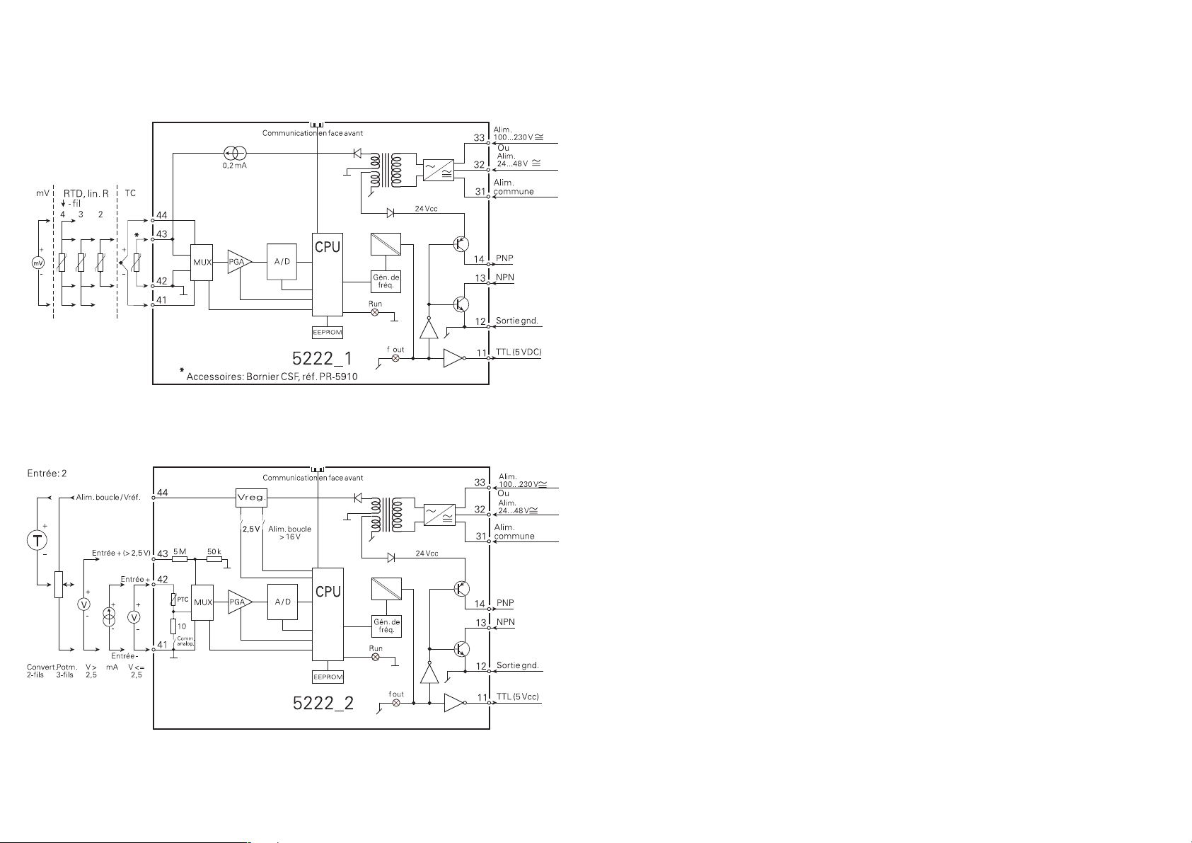
SCHEMAS DE PRINCIPE :
PROGRAMMIERBARER I/f-WANDLER
PRecon Typ 5222
INHALTSVERZEICHNIS
Warnung . . . . . . . . . . . . . . . . . . . . . . . . . . . . . . . . . . . . . . 48
Sicherheitsregeln. . . . . . . . . . . . . . . . . . . . . . . . . . . . . . . . 50
Konformitätserklärung. . . . . . . . . . . . . . . . . . . . . . . . . . . . 52
Zerlegung des Systems 5000 . . . . . . . . . . . . . . . . . . . . . . 53
Allgemeines . . . . . . . . . . . . . . . . . . . . . . . . . . . . . . . . . . . . 54
Eingangstypen für 5222 A1. . . . . . . . . . . . . . . . . . . . . . . . 54
Fühler- und Kabelfehler. . . . . . . . . . . . . . . . . . . . . . . . . . . 55
Eingangstypen für 5222 A2. . . . . . . . . . . . . . . . . . . . . . . . 55
Hilfsversorgungen . . . . . . . . . . . . . . . . . . . . . . . . . . . . . . . 55
Ausgänge . . . . . . . . . . . . . . . . . . . . . . . . . . . . . . . . . . . . . 55
Linearisierung . . . . . . . . . . . . . . . . . . . . . . . . . . . . . . . . . . 55
Konfiguration . . . . . . . . . . . . . . . . . . . . . . . . . . . . . . . . . . . 56
Elektrische Daten . . . . . . . . . . . . . . . . . . . . . . . . . . . . . . . 56
Bestellangaben . . . . . . . . . . . . . . . . . . . . . . . . . . . . . . . . . 61
5222 Verbindung mit Loop Link . . . . . . . . . . . . . . . . . . . . 61
Blockdiagramme . . . . . . . . . . . . . . . . . . . . . . . . . . . . . . . . 62
4746
Page 26
ALLGE-
MEINES
GEFÄHR-
LICHE
SPANNUNG
WARNUNG
Dieses Modul ist für den Anschluss an lebensgefährliche elektrische Spannungen gebaut. Missachtung dieser Warnung
kann zu schweren Verletzungen oder mechanischer Zerstörung
führen. Um eine Gefährdung durch Stromstöße oder Brand
zu vermeiden müssen die Sicherheitsregeln des Handbuches
eingehalten, und die Anweisungen befolgt werden.
Die Spezifikationswerte dürfen nicht überschritten werden, und
das Modul darf nur gemäß folgender Beschreibung benutzt
werden. Das Handbuch ist sorgfältig durchzulesen, ehe das
Modul in Gebrauch genommen wird. Nur qualifizierte Personen
(Techniker) dürfen dieses Modul installieren.
Wenn das Modul nicht wie in diesem Handbuch beschrieben
benutzt wird, werden die Schutzeinrichtungen des Moduls
be einträchtigt.
WARNUNG
Vor dem abgeschlossenen festen Einbau des Moduls darf
daran keine gefährliche Spannung angeschlossen werden, und
fol gen de Maßnahmen sollten nur in spannungslosem Zustand
des Mo duls und unter ESD-sicheren Verhältnisse durchgeführt
werden:
Öffnen des Moduls zum Einstellen von Umschaltern und
Überbrückern.
Installation, Montage und Demontage von Leitungen.
Fehlersuche im Modul.
Reparaturen des Moduls und Austausch von Sicherungen
dürfen nur von PR electronics A/S vorgenommen werden.
ZEICHENERKLÄRUNGEN:
Dreieck mit Ausrufungszeichen: Warnung / Vorschrift. Vor gänge,
die zu lebensgefährlichen Situationen führen können.
Die CE-Marke ist das sichtbare Zeichen dafür, dass das Modul
die Vorschriften erfüllt.
Doppelte Isolierung ist das Symbol dafür, dass das Modul
besondere Anforderungen an die Isolierung erfüllt.
INSTAL-
LATION
WARNUNG
Das System 5000 muss auf eine DIN-Schiene nach DIN 46277
montiert werden.
Der Verbindungsstecker im SYSTEM 5000 ist an Eingangsterminale angeschlossen, in denen gefährliche Spannungen auftreten
können, und ein Anschluss an die Programmierungseinheit
Loop Link ist nur über das beigefügte Kabel zulässig.
4948
Page 27

SICHERHEITSREGELN
DEFINITIONEN:
Gefährliche Spannungen sind definitionsgemäß die Bereiche: 75...1500 Volt
Gleichspannung und 50...1000 Volt Wechselspannung.
Techniker sind qualifizierte Personen, die dazu ausgebildet oder angelernt sind,
eine Installation, Bedienung oder evtl. Fehlersuche auszuführen, die sowohl
technisch als auch sicherheitsmäßig vertretbar ist.
Bedienungspersonal sind Personen, die im Normalbetrieb mit dem Produkt die
Drucktasten oder Potentiometer des Produktes einstellen bzw. bedienen und
die mit dem Inhalt dieses Handbuches vertraut gemacht wurden.
Die Installation und der Anschluss des Moduls haben in Übereinstimmung mit
den geltenden Regeln des jeweiligen Landes bez. der Installation elektrischer
Apparaturen zu erfolgen, u.a. bezüglich Leitungsquerschnitt, (elektrischer) VorAbsicherung und Positionierung.
Eine Beschreibung von Eingangs- / Ausgangs- und Versorgungsanschlüssen
befindet sich auf dem Blockschaltbild und auf dem seitlichen Schild.
Für Module, die dauerhaft an eine gefährliche Spannung angeschlossen sind,
gilt:
Die maximale Größe der Vorsicherung beträgt 10 A und muss zusammen mit einem Unterbrecherschalter leicht zugänglich und nahe am
Modul angebracht sein. Der Unterbrecherschalter soll derart gekennzeichnet sein, dass kein Zweifel darüber bestehen kann, dass er die
Spannung für das Modul unterbricht.
EMPFANG UND AUSPACKEN:
Packen Sie das Modul aus, ohne es zu beschädigen und sorgen Sie dafür, dass
das Handbuch stets in der Nähe des Moduls und zugänglich ist.
Die Verpackung sollte beim Modul bleiben, bis dieses am endgültigen Platz
montiert ist.
Kontrollieren Sie beim Empfang, ob der Modultyp Ihrer Bestellung entspricht.
UMGEBUNGSBEDINGUNGEN:
Direkte Sonneneinstrahlung, starke Staubentwicklung oder Hitze, mechanische
Erschütterungen und Stöße sind zu vermeiden; das Modul darf nicht Regen
oder starker Feuchtigkeit ausgesetzt werden. Bei Bedarf muss eine Erwärmung,
welche die angegebenen Grenzen für die Umgebungstemperatur überschreitet,
mit Hilfe eines Kühlgebläses verhindert werden.
Alle Module gehören der Installationskategorie II, dem Verschmutzungsgrad 1
und der Isolationsklasse II an.
INSTALLATION:
Das Modul darf nur von Technikern angeschlossen werden, die mit den technischen Ausdrücken, Warnungen und Anweisungen im Handbuch vertraut sind
und diese befolgen.
Sollten Zweifel bezüglich der richtigen Handhabung des Moduls bestehen,
sollte man mit dem Händler vor Ort Kontakt aufnehmen. Sie können aber auch
direkt mit PR electronics GmbH, Bamlerstraße 92, D-45141 Essen, (Tel.: (0)
201 860 6660) oder mit PR electronics A/S, Lerbakken 10, DK-8410 Rønde,
Dänemark (Tel.: +45 86 37 26 77) Kontakt aufnehmen.
KALIBRIERUNG UND JUSTIERUNG:
Während der Kalibrierung und Justierung sind die Messung und der Anschluss
externer Spannungen entsprechend diesem Handbuch auszuführen, und der
Techniker muss hierbei sicherheitsmäßig einwandfreie Werkzeuge und Instrumente benutzen.
BEDIENUNG IM NORMALBETRIEB:
Das Bedienungspersonal darf die Module nur dann einstellen oder bedienen,
wenn diese auf vertretbare Weise in Schalttafeln o. ä. fest installiert sind, so
dass die Bedienung keine Gefahr für Leben oder Material mit sich bringt. D. h.,
es darf keine Gefahr durch Berührung bestehen, und das Modul muss so plaziert sein, dass es leicht zu bedienen ist.
REINIGUNG:
Das Modul darf in spannungslosem Zustand mit einem Lappen gereinigt werden, der mit destilliertem Wasser oder Spiritus leicht angefeuchtet ist.
HAFTUNG:
In dem Umfang, in welchem die Anweisungen dieses Handbuches nicht
genau eingehalten werden, kann der Kunde PR electronics gegenüber keine
Ansprüche geltend machen, welche ansonsten entsprechend der eingegangenen Verkaufs vereinbarungen existieren können.
5150
Page 28
KONFORMITÄTSERKLÄRUNG
Als Hersteller bescheinigt
PR electronics A/S
Lerbakken 10
DK-8410 Rønde
hiermit für das folgende Produkt:
Typ: 5222
Name: Programmierbarer I/f-Wandler
die Konformität mit folgenden Richtlinien und Normen:
EMV Richtlinien 2004/108/EG und nachfolgende Änderungen
EN 61326
Diese Erklärung ist in Übereinstimmung mit Artikel 10, Unterklausel 1 der EMV
Richtlinie ausgestellt. Zur Spezifikation des zulässigen Erfüllungsgrades, siehe
die Elektrische Daten des Moduls.
Die Niederspannungsrichtlinien 73/23/EWG und nachfolgende Änderungen
EN 61010-1
Die CE Marke für Konformität mit den Niederspannungsrichtlinien wurde im
Jahre 1997 hinzugefügt.
ZERLEGUNG DES SYSTEMS 5000
Zunächst ist gefährliche Spannung von den Anschlussklemmen zu trennen. Das
Modul wird von der DIN-Schiene gelöst, indem man den unteren Verschluss
löst, wie in Abb. 1 dargestellt. Die Platine wird daraufhin herausgenommen,
indem man den oberen Verschluss anhebt und gleichzeitig die Frontab deckung
herauszieht (siehe Abb. 2).
Jetzt können Schalter und Überbrücker verändert werden.
Der Programmierungsstecker wird zugänglich, indem man die Frontabdeckung
öffnet, wie in Abb. 3 gezeigt.
Abb.1: Lösen aus der DIN-Schiene.
Abb. 3: Zugang zum Programmierungs stecker.
Rønde, 20. Dez. 2005 Peter Rasmussen
Unterschrift des Herstellers
Abb. 2 Herausnehmen der Platine.
5352
Page 29

PROGRAMMIERBARER I/f WANDLER
5222
• Eingänge: TE / WTH, linearer Widerstand, mV oder
mA sowie V
• Frequenzausgang NPN, PNP, TTL
• Programmierbar über PC
• Galvanisch isoliert, 3,75 kVAC
• Gleich- oder Wechselstromversorgung
• DIN-Schienenmontierung
ALLGEMEINES:
Der PRecon-Wandler 5222 wird für die jeweilige Aufgabe mit Hilfe eines Standard-PCs und des Programmiersatzes Loop Link konfiguriert. Der Wandler kann
vor der Installation oder direkt im Betrieb konfiguriert werden.
PRecon 5222 kann auch nach Spezifikationen fertig konfiguriert geliefert werden
(siehe Optionsverzeichnis im Datenblatt).
EINGANGSTYPEN FÜR 5222 A1:
WTH-Eingang für Pt100/Ni100 in Temperaturbereichen gemäß IEC 751, DIN
43760. Über Loop Link kann man den Kabelwiderstand bei 2-Leiter-Anschluss
messen und kompensieren.
Automatische Kabelkompensation bei 3- oder 4-Leiter-Anschluss.
FÜHLER- UND KABELFEHLER:
Bei Fühler- und / oder Kabelfehler für TE-,WTH- und Widerstandseingang kann
der Ausgang so programmiert werden, dass er einen frei wählbaren festen Wert
annimmt.
EINGANGSTYPEN FÜR 5222 A2:
Stromeingang für Signale bis zu 100 mADC. Der Eingang ist mit einem PTC-
Widerstand geschützt.
Spannungseingang für Signale bis zu 250 VDC.
HILFSVERSORGUNGEN:
2-Draht-Versorgung 16...28 VDC / 20 mA zur Versorgung von 2-Draht-Mess-
umformer.
Bezugsspannung 2,5 VDC / 15 mA als Bezug für 3-Leiter-Potentiometer.
AUSGÄNGE:
Die PNP-, NPN- und TTL-Ausgänge sind galvanisch von Versorgung und Eingang
getrennt.
Die Ausgänge sind strombegrenzt mittels PTC-Widerständen.
Es ist möglich, die Ausgänge im Verhältnis zum Eingang zu invertieren.
Die Impulszeit kann frei gewählt werden.
Vom PReset kann ein sog. „LOW CUT OFF«-Wert gewählt werden. Das bedeutet,
dass der Ausgang auf 0 Hz gehalten wird, wenn der Eingang unter dem „LOW
CUT OFF«-Wert liegt.
Die Ansprechzeit ist programmierbar.
Thermoelementeingang (TE) für genormte Thermoelemente in Temperaturbereichen gemäß IEC 584, DIN 43710 oder ASTM E988-90. Interne Vergleichsstellenkompensation (CJC) mit Pt100-Fühler in der Anschlussklemme (Option Typ
5910 und 5913), externe CJC mit Pt100/Ni100 bei 2-Leiter-Anschluss oder feste
CJC (Thermostatbox).
Widerstandseingang für die Messung bis zu 5000 Ω mit Kabelkompensation bei
3- oder 4-Leiter-Anschluss.
mV-Eingang für Gleichspannungssignale.
54
NPN- und PNP-Ausgänge für externes Relais, elektromechanischen Zähler,
PLC-Eingang oder entsprechende Belastung.
Ein aktiver Ausgang wird hergestellt, indem man NPN mit dem PNP-Ausgang
verbindet (Klammer von Kontaktstift 13 zu Kontaktstift 14).
Der PNP-Ausgang kann Impulse zu 20 ms an elektromechanische Zähler
ab geben.
LINEARISIERUNG:
Das Ausgangssignal ist entsprechend der gewählten Fühlernorm linearisiert,
jedoch ist es auch möglich, kundenspezifische Linearisierungen einzugeben.
55
Page 30
KONFIGURATION:
Loop Link enthält PReset-Software, Adapter, Kabel etc.
Der Adapter besitzt eine galvanische Isolation zum Schutz des PCs.
Die Kommunikation zwischen PRecon 5222 und Loop Link erfolgt in beiden
Richtungen, so dass die Konfiguration mit Seriennummer und Typenschildnummer bei Änderung der Konfigurationsänderungen oder Kontrollen abgerufen
werden kann.
Max. Leiterquerschnitt ............................... 1 x 2,5 mm2 Litzendraht
Klemmschraubenanzugsmoment ............... 0,5 Nm
Relative Luftfeuchtigkeit ............................. < 95% (nicht kond.)
Abmessungen (HxBxT) ............................... 109 x 23,5 x 130 mm
DIN-Schiene Typ ........................................ DIN 46277
Schutzart (Gehäuse / Klemmen) ................ IP50 / IP20
Gewicht ...................................................... 250 g
ELEKTRISCHE DATEN - TYP 5222:
Umgebungstemperatur:
-20°C bis +60°C
Allgemeine Daten:
Versorgungsspannung
Version 5222---A- .................................... 19,2...78 VDC
21,6...52,8 VAC
Version 5222---B- .................................... 80...300 VDC
72,8...253 VAC
Frequenz .................................................. 50...60 Hz
Eigenverbrauch .......................................... ≤ 2,6 W
Sicherung ................................................... 400 mA T / 250 VAC
Isolation, Test / Betrieb .............................. 3,75 kVAC / 250 VAC
Kommunikationsschnittstelle ..................... Loop Link
Ansprechzeit (programmierbar)
Version 5222-1-- (Temp. Vers.) ................ 350 ms...60 s
Version 5222-2-- (mA / V Vers.) ............... 200 ms...60 s
Aktualisierungszeit
Version 5222-1-- (Temp. Vers.) ................ 100 ms
Version 5222-1-- (mA / V Vers.) ............... 60 ms
Signaldynamik, Eingang ............................. 20 bit
Kalibrierungstemperatur ............................. 20...28°C
Temperaturkoeffizient ................................. < ±0,01% d. Messspanne/°C
Linearitätsfehler .......................................... < 0,1% d. Messspanne
Beeinflussung durch eine
Versorgungsspannungsänderung .............. < 0,005% d. Messspanne / V
Hilfsspannungen Typ 5222-2:
Referenzspannung ..................................... 2,5 VDC ±0,5% / 15 mA
2-Draht-Versorgung .................................... 28 VDC / 0 mA
16 VDC / 20 mA
EMV-Immunitätseinfluss ............................. < ±0,5%
Elektrische Daten - EINGANG Typ 5222-1:
TE-Eingang:
Min. Max. Min.
Typ Temperatur Temperatur Spanne Norm
B +400°C +1820°C 200°C IEC584
E -200°C +1000°C 50°C IEC584
J -210°C +1200°C 50°C IEC584
K -180°C +1372°C 50°C IEC584
L -200°C +900°C 50°C DIN43710
N -180°C +1300°C 100°C IEC584
R -50°C +1760°C 200°C IEC584
S -50°C +1760°C 200°C IEC584
T -200°C +400°C 50°C IEC584
U -200°C +600°C 50°C DIN43710
W3 0°C +2300°C 200°C ASTM E988-90
W5 0°C +2300°C 200°C ASTM E988-90
Max. Nullpunktverschiebung ...................... 50% d. gewählten Maximalwertes
Fühlerstrom ................................................ Nom. 100 nA
Grundgenauigkeit:
Typ E,J,K,L,N,T,U ....................................... < ±1°C
Typ B,R,S,W3,W5 ....................................... < ±2°C
Vergleichsstellenkompensation (CJC) ........ < ±1°C
Temperaturkoeffizient:
Typ E,J,K,L,N,T,U
Messspanne < 500°C ........................ ±0,05°C / °C
Messspanne > 500°C ........................ ±0,01% d. Messspanne / °C
Typ B,R,S,W3,W5 ....................................... 0,2°C / °C
Fühlerfehleranzeige (Ausgang) ................... Upscale / downscale
Umg.
Umg.
Umg.
56
57
Page 31
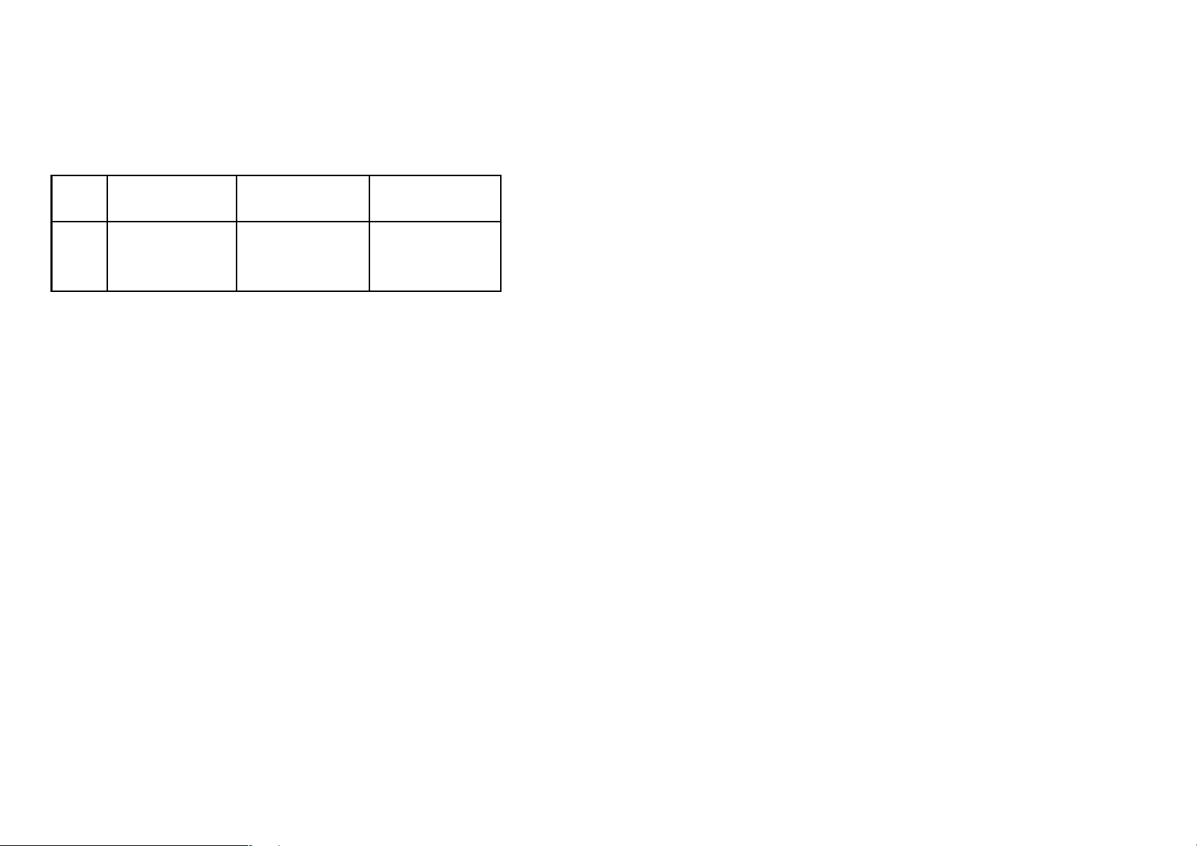
mV-Eingang:
Messbereich ............................................... 0...100 mV
Min. Messbereich ....................................... 5 mV
Max. Nullpunktverschiebung ...................... 50% d. gewählten Maximalwertes
Eingangswiderstand ................................... Nom. 10 MΩ
WTH-Eingang:
WTH- Min. Max. Min.
Typ Wert Wert Spanne
Eingangswiderstand ≤ 2,5 VDC ................. Nom. 10 MΩ
> 2,5 VDC ................. Nom. 5 MΩ
Stromeingang:
Messbereich ............................................... 0...100 mA
Min. Messbereich (Messspanne) ................ 4 mA
Max. Nullpunktverschiebung ...................... 50% d. gewählten Maximalwertes
Eingangswiderstand:
Versorgte Einheit ........................................ Nom. 10 Ω + PTC 10 Ω
Nicht versorgte Einheit ............................... R
SHUNT
= ∞, U
Abfall
< 6 V
Pt100 -200°C +850°C 25°C
Ni100 -60°C +250°C 25°C
Lin. R. 0 Ω 5000 Ω 30 Ω
Max. Nullpunktverschiebung ...................... 50% d. gewählten Maximalwertes
Max. Kabelwiderstand pro Leiter ............... 10 Ω
Fühlerstrom ................................................ Nom. 0,2 mA
Grundgenauigkeit ....................................... < ±0,2°C
Temperaturkoeffizient:
Messspanne < 100°C ........................ ±0,01°C/°C
Messspanne > 100°C ........................ ±0,01% d. Messspanne /°C
Beeinflussung durch den Fühler-
kabelwiderstand (3- / 4-Leiter) ................... < 0,002 Ω/Ω
Fühlerfehleranzeige (Ausgang) ................... Upscale / downscale
Linearer Widerstandseingang:
Messbereich ............................................... 0...5000 Ω
Min. Messbereich (Messspanne) .............. 30 Ω
Max. Nullpunktverschiebung ...................... 50% d. gewählten Maximalwertes
Max. Kabelwiderstand pro Leiter ............... 10 Ω
Fühlerstrom ................................................ Nom. 0,2 mA
Beeinflussung durch den Fühler-
kabelwiderstand (3- / 4-Leiter) ................... < 0,002 Ω/Ω
Fühlerfehleranzeige (Ausgang) ................... Upscale / downscale
Elektrische Daten - EINGANG Typ 5222-2
Spannungseingang:
Messbereich ............................................... 0...250 VDC
Min. Messbereich (Messspanne) ................ 50 mVDC
Max. Nullpunktverschiebung ...................... 50% d. gewählten Maximalwertes
Umg.
Umg.
Elektrische Daten - AUSGÄNGE:
Frequenzbereich ......................................... 0,00005...25000 Hz
Min. Frequenz (Messspanne) ..................... 0,00005 Hz
Duty cycle (0 ... 25000 Hz) ......................... 50%
oder
Programmierbare Pulszeit (f < 500 Hz) ...... 1...1000 ms
Max. 90% duty cycle
PNP-Ausgang:
I
max. .................................................. 30 mA
.
Aus
I
max. Scheitel ..................................... 170 mA
Aus.
U
min./max. ......................................... 22 / 26 V
Aus.
C
.......................................................... 10 nF
Aus.
R
typ. ................................................... 25 Ω
Aus.
Elektromechanischer Zähler ....................... 24 V / 135 mA / 20 ms
NPN-Ausgang:
I
max. ................................................... 150 mA
sink
I
max. Scheitel ..................................... 300 mA
sink
Max. Eingang ............................................. 55 V
C
.......................................................... 10 nF
Aus.
R
typ. ................................................... 10 Ω
Aus.
TTL-Ausgang:
I
sink
I
sink
U
C
R
/Quelle
/Quelle
Aus.
Aus
Aus.
min. ......................................... 15 mA
Scheitel ................................... 100 mA
.......................................................... 5 V ±5%
.......................................................... 10 nF
.
typ. ................................................... 55 Ω
5958
Page 32
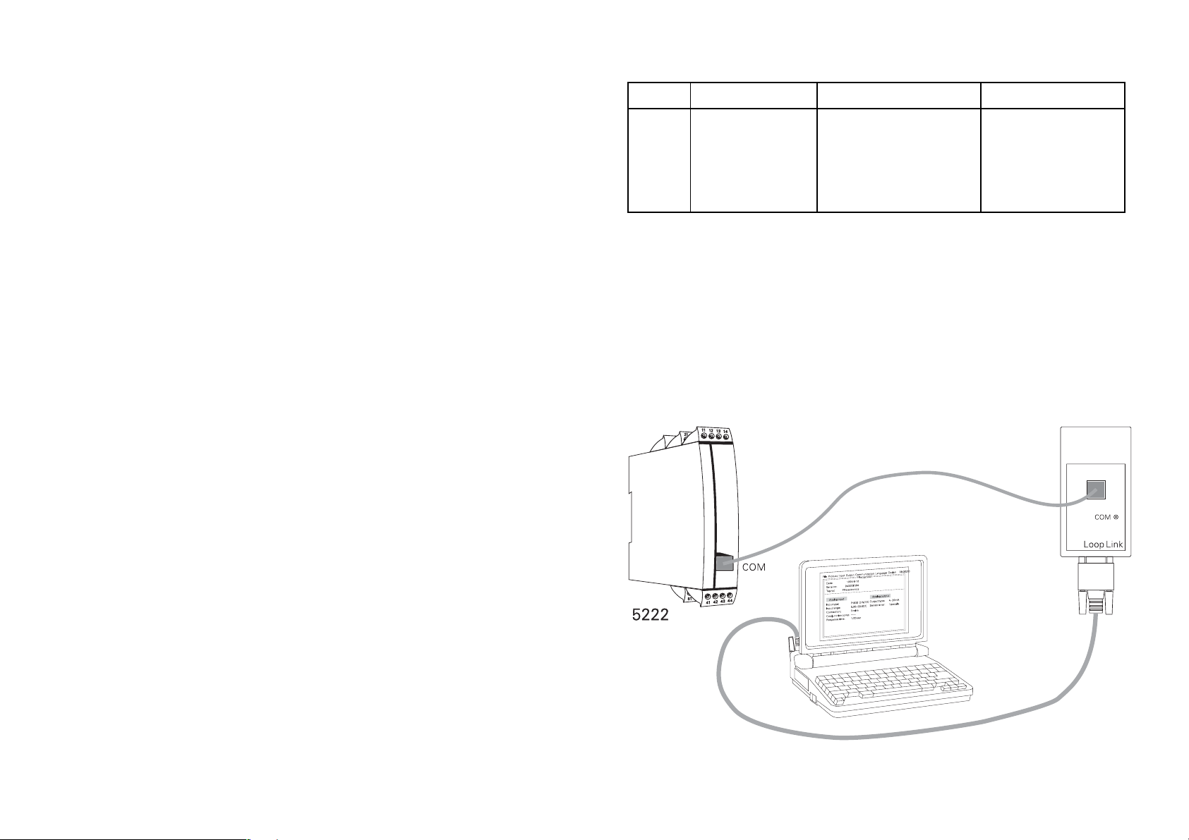
GOST R Zulassung;
VNIIM .......................................................... Cert. no. Ross DK.ME48.V01899
Eingehaltene Behördenvorschriften: Norm:
EMV 2004/108/EG
Emission und Immunität .................... EN 61326
LVD 73/23/EWG ......................................... EN 61010-1
PELV/SELV .................................................. IEC 364-4-41 und EN 60742
d. Messspanne = der gewählten Messspanne
BESTELLANGABEN: 5222
Typ Version Eingang
5222 Standard : A
Zu beachten!
Für TE-Eingänge mit interner Vergleichsstellenkompensation (CJC) ist die
Anschlussklemme Typ 5910 zu bestellen.
5222 VERBINDUNG MIT LOOP LINK:
WTH / TE / mV / R : 1
mA / V / mV : 2
Versorgung
24...65 VDC / : A
24...48 VAC
100...250 VDC / : B
80...230 VAC
60
61
Page 33
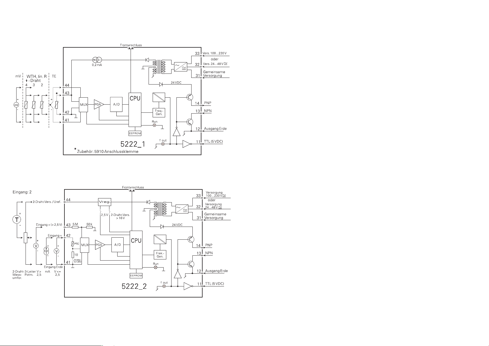
BLOCKDIAGRAMME:
62
Page 34
DK
PR electronics A/S tilbyder et bredt program af analoge og digitale signalbehandlingsmoduler til industriel automation. Vores
kompetenceområder omfatter: Isolation, Displays, Ex-barrierer,
Temperatur samt Universal-moduler. Alle produkter opfylder de
strengeste internationale standarder, og størstedelen integrerer
den patenterede STREAM-SHIELD teknologi, der sikrer driftsikkerhed i selv de værste omgivelser. Vores motto »Signals the Best«
er indbegrebet af denne fi losofi – og din garanti for kvalitet.
UK
PR electronics A/S offers a wide range of analogue and digital
signal conditioning modules for industrial automation. Our areas
of competence include: Isolation, Displays, Ex barriers, Temperature, and Universal Modules. All products comply with the
most exacting international standards and the majority feature
our patented STREAM-SHIELD technology ensuring reliability in
even the worst of conditions. »Signals the Best« is the epitome
of our philosophy – and your guarantee for quality.
Subsidiaries
France
PR electronics Sarl
Zac du Chêne, Activillage
2, allée des Sorbiers,
F-69500 Bron
Germany
PR electronics GmbH
Bamlerstraße 92
D-45141 Essen
Italy
PR electronics S.r.l.
Via Giulietti, 8
IT-20132 Milano
Spain
PR electronics S.L.
Avda. Meridiana 354, 6°-A
E-08027 Barcelona
[email protected]
tel. +33 (0) 4 72 14 06 07
fax +33 (0) 4 72 37 88 20
[email protected]
tel. +49 (0) 201 860 6660
fax +49 (0) 201 860 6666
[email protected]
tel. +39 02 2630 6259
fax +39 02 2630 6283
[email protected]
tel. +34 93 311 01 67
fax +34 93 311 08 17
FR
PR electronics A/S offre une large gamme de produits pour le
traite ment des signaux analogiques et numériques dans tous les
domaines industriels. Nos compétences s’étendent des transmetteurs de température aux affi cheurs, des isolateurs aux barrières SI,
jusqu’aux modules universels. Tous nos produits sont conformes
aux normes internationales les plus strictes et la majorité d’entre
eux répondent même à la technologie brevetée STREAM-SHEILD
qui garantie un fonctionnement fi able sous les conditions les plus
défavorables. Notre devise »SIGNALS the BEST« c’est notre ligne
de conduite - et pour vous l’assurance de la meilleure qualité.
DE
PR electronics A/S verfügt über ein breites Produktprogramm an
analogen und digitalen Signalverarbeitungsmodule für die industrielle Automatisierung. Unsere Kompetenzbereiche umfassen:
Displays, Temperaturtransmitter, Ex- und galvanische Signaltrenner, und Universalgeräte. Alle Produkte von PR electronics
werden in Überein stimmung mit den strengsten internationalen
Normen produziert. Für die Mehrzahl aller Produkte garantiert
die patentierte STREAM-SHIELD Technologie höchste Zuverlässigkeit auch unter schwierigsten Einsatzbedingungen. »Signals
the Best« ist Ihre Garantie für Qualität!
Sweden
PR electronics AB
August Barks gata 6A
S-421 32 Västra Frölunda
UK
PR electronics Ltd
Fairlie Quay Enterprise Park
Main Road, Fairlie
Ayrshire, KA29 0AS
USA
PR electronics Inc
16776 Bernardo Center Drive
Suite 203
San Diego, California 92128
[email protected]
tel. +46 (0) 3149 9990
fax +46 (0) 3149 1590
[email protected]
tel. +44 (0) 1475 568 000
fax +44 (0) 1475 568 222
[email protected]
tel. +1 858 521 0167
fax +1 858 521 0945
Head offi ce
Denmark www.prelectronics.com
PR electronics A/S [email protected]
Lerbakken 10 tel. +45 86 37 26 77
DK-8410 Rønde fax +45 86 37 30 85
 Loading...