

Page 1
PERFORMANCE
MADE
SMARTER
Product Manual
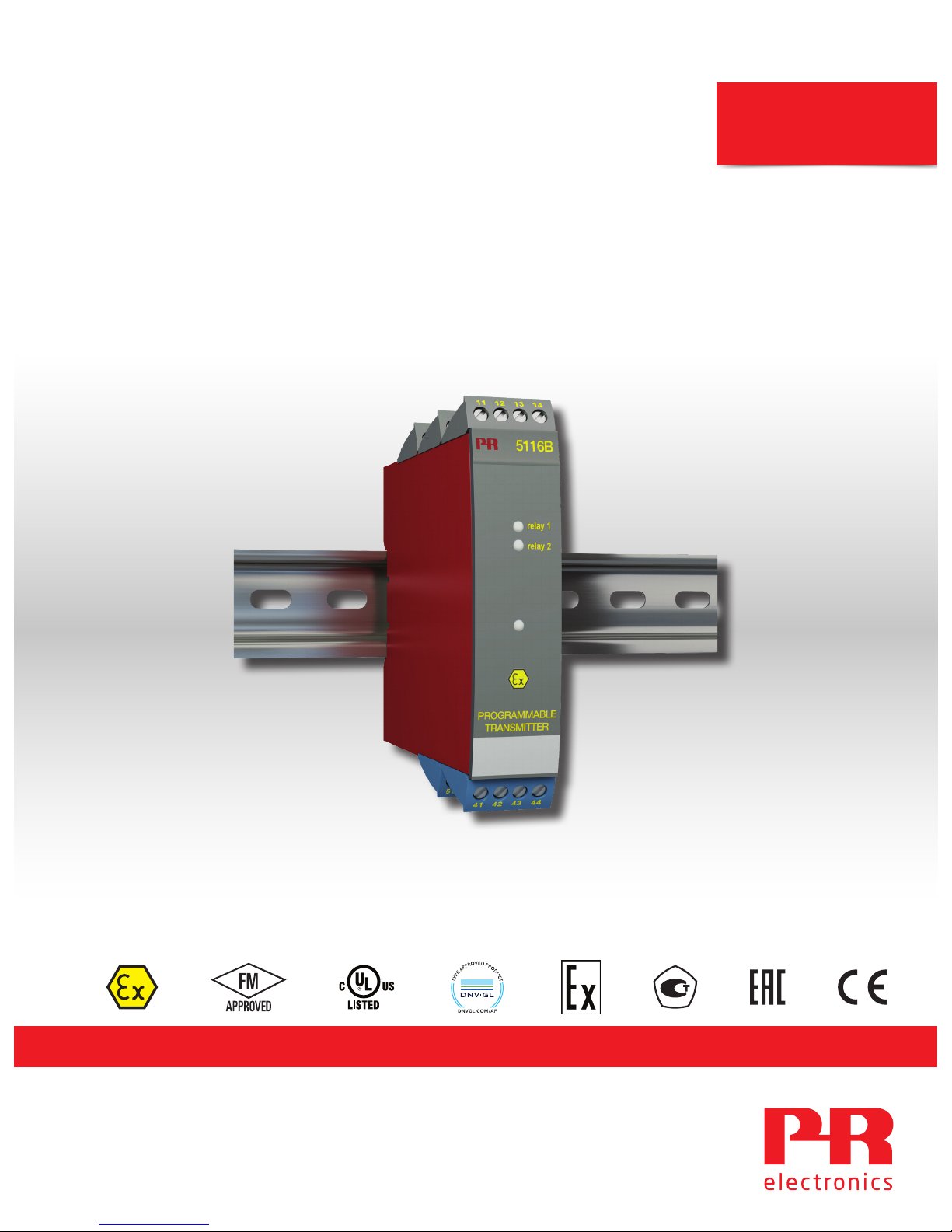
5116
Programmable transmitter
TEMPERATURE | I.S. INTERFACES | COMMUNICATION INTERFACES | MULTIFUNCTIONAL | ISOLATION | DISPLAY
No. 5116V104-UK
From serial no. 181570001
Page 2

Communication
Display
I.S. Interface
Isolation
Multifunction
Temperature
6 Product Pillars
to meet your every need
With our innovative, patented technologies, we make signal conditioning smarter and simpler. Our portfolio is composed of six
product areas, where we offer a wide range of analog and digital devices covering over a thousand applications in industrial
and factory automation. All our products comply with or surpass the highest industry standards, ensuring reliability in even
the harshest of environments and have a 5-year warranty for greater peace of mind.
Individually outstanding, unrivalled in combination
Our range of temperature transmitters and sensors provides the highest level of signal integrity from the
measurement point to your control system. You can convert industrial process temperature signals to analog, bus or
digital communications using a highly reliable point-to-point solution with a fast response time, automatic selfcalibration, sensor error detection, low drift, and top EMC performance in any environment.
Our unique range of single devices covering multiple applications is easily deployable as your site standard. Having
one variant that applies to a broad range of applications can reduce your installation time and training, and greatly
simplify spare parts management at your facilities. Our devices are designed for long-term signal accuracy, low
power consumption, immunity to electrical noise and simple programming.
We provide inexpensive, easy-to-use, future-ready communication interfaces that can access your PR installed base
of products. The detachable 4501 Local Operator Interface (LOI) allows for local monitoring of process values,
device configuration, error detection and signal simulation. The next generation, our 4511 Remote Operator
Interface (ROI) does all that and more, adding remote digital communications via Modbus/RTU, while the analog
output signals are still available for redundancy.
With the 4511 you can further expand connectivity with a PR gateway, which connects via industrial Ethernet,
wirelessly through a Wi-Fi router or directly with the devices using our Por table Plant Supervisor (PPS) application.
The PPS app is available for iOS, Android and Windows.
Our display range is characterized by its flexibility and stability. The devices meet nearly every demand for display
readout of process signals, and have universal input and power supply capabilities. They provide a real-time
measurement of your process value no matter the industry, and are engineered to provide a user-friendly and
reliable relay of information, even in demanding environments.
We deliver the safest signals by validating our products against the toughest safety standards. Through our
commitment to innovation, we have made pioneering achievements in developing I.S. interfaces with SIL 2 Full
Assessment that are both efficient and cost-effective. Our comprehensive range of analog and digital intrinsically
safe isolation barriers offers multifunctional inputs and outputs, making PR an easy-to-implement site standard.
Our backplanes further simplify large installations and provide seamless integration to standard DCS systems.
Our compact, fast, high-quality 6 mm isolators are based on microprocessor technology to provide exceptional
performance and EMC-immunity for dedicated applications at a very low total cost of ownership. They can be
stacked both vertically and horizontally with no air gap separation between units required.
Page 3

5116V104-UK 3
Programmable transmitter
5116
Table of contents
Warning ................................................................................................ 4
Symbol identification .................................................................................... 4
Safety instructions ...................................................................................... 5
Instructions for intrinsically safe installation of 5116B..................................................... 5
How to demount system 5000 ........................................................................... 6
Application ............................................................................................. 8
Technical characteristics ................................................................................. 8
Mounting / installation................................................................................... 8
Order ................................................................................................... 9
Electrical specifications.................................................................................. 9
Connections ............................................................................................ 14
Block diagram........................................................................................... 16
Graphic depiction of relay actions Increasing / Decreasing .................................................. 17
Graphic depiction of relay action Window.................................................................. 17
5116 connection to Loop Link............................................................................ 18
Activation of the process calibration button . . . . . . . . . . . . . . . . . . . . . . . . . . . . . . . . . . . . . . . . . . . . . . . . . . . . . . . . . . . . . . . 18
Configuration of relay 1 & 2 in PReset .................................................................... 19
Process calibration 0% and 100% or only 0% .............................................................. 20
Error functions .......................................................................................... 20
Appendix . . . . . . . . . . . . . . . . . . . . . . . . . . . . . . . . . . . . . . . . . . . . . . . . . . . . . . . . . . . . . . . . . . . . . . . . . . . . . . . . . . . . . . . . . . . . . . . 21
FM control drawing no. 5116QF01..................................................................... 22
Page 4
4 5116V104-UK
Warning
This device is designed for connection to hazardous electric voltages.
Ignoring this warning can result in severe personal injury or mechanical damage.
To avoid the risk of electric shock and fire, the safety instructions of this manual must be observed and
the guidelines followed.
The specifications must not be exceeded, and the device must only be applied as described in the
following.
Prior to the commissioning of the device, this manual must be examined carefully.
Only qualified personnel (technicians) should install this device.
If the equipment is used in a manner not specified by the manufacturer, the protection provided by the
equipment may be impaired.
Warning
Until the device is fixed, do not connect hazardous voltages to the device.
The following operations should only be carried out on a disconnected device and under ESD-safe
conditions:
General mounting, wire connection and disconnection.
Troubleshooting the device.
Repair of the device and replacement of circuit breakers must be done by PR electronics A/S only.
Warning
To keep the safety distances, the relay contacts on the device must not be connected to both hazardous
and non-hazardous voltages at the same time.
SYSTEM 5000 must be mounted on a DIN rail according to DIN 46277.
The communication connector of SYSTEM 5000 is connected to the input terminals on which dangerous
voltages can occur, and it must only be connected to the programming unit Loop Link by way of the
enclosed cable.
Symbol identification
Triangle with an exclamation mark: Read the manual before installation and commissioning of the
device in order to avoid incidents that could lead to personal injury or mechanical damage. Warning /
demand. Potentially lethal situations.
The CE mark proves the compliance of the device with the essential requirements of the directives.
The double insulation symbol shows that the device is protected by double or reinforced insulation.
Ex devices have been approved acc. to the ATEX directive for use in connection with installations in
explosive areas.
HAZARD-
OUS
VOLTAGE
INSTAL-
LATION
GENERAL
Page 5

5116V104-UK 5
Safety instructions
Definitions
Hazardous voltages have been defined as the ranges: 75 to 1500 Volt DC, and 50 to 1000 Volt AC.
Technicians are qualified persons educated or trained to mount, operate, and also trouble-shoot technically correct and in
accordance with safety regulations.
Operators, being familiar with the contents of this manual, adjust and operate the knobs or potentiometers during normal
operation.
Receipt and unpacking
Unpack the device without damaging it and check whether the device type corresponds to the one ordered. The packing
should always follow the device until this has been permanently mounted.
Environment
Avoid direct sun light, dust, high temperatures, mechanical vibrations and shock, and rain and heavy moisture. If necessary,
heating in excess of the stated limits for ambient temperatures should be avoided by way of ventilation.
All devices fall under Installation Category II, Pollution Degree 2, and Insulation Class II.
Mounting
Only technicians, who are familiar with the technical terms, warnings, and instructions in the manual and who are able to
follow these, should connect the device. Should there be any doubt as to the correct handling of the device, please contact
your local distributor or, alternatively,
PR electronics A/S
www.prelectronics.com
Mounting and connection of the device should comply with national legislation for mounting of electric materials, i.e. wire
cross section, protective fuse, and location. Descriptions of input / output and supply connections are shown in the block
diagram and side label.
The following apply to fixed hazardous voltages-connected devices:
The max. size of the protective fuse is 10 A and, together with a power switch, it should be easily accessible and close to
the device. The power switch should be marked with a label telling it will switch off the voltage to the device.
Year of manufacture can be taken from the first two digits in the serial number.
Instructions for intrinsically safe installation of 5116B
The intrinsically safe circuits are galvanically connected to the communications interface unit.
The communications interface may only be connected temporarily, under the condition that the connectors with terminal
numbers 41...44 and 51...54 are disconnected on the 5116B.
When a higher ingress protection than IP20 is required, this has to be achieved by an additional enclosure which is suitable for
the applicable environmental conditions.
When two or more units are placed next to each other it has to be assured that all the terminal numbers 41...44 and 51...54
are placed on the same side and are separated from the non-intrinsically safe circuits of the units which could be mounted
above or below it.
Each combination of circuits (to terminations 41...44 or to terminations 51...53 or to terminations 51...54) shall be connected
via separated cables or if the combinations are in one cable shall be type A or B in accordance with EN 60079-14 Clause
12.2.2.8.
UL installation requirements
Use 60/75°C copper conducters only.
For use only in pollution degree 2 or better.
Max. ambient temperature . . . . . . . . . . . . . . . . . . . . . . . . . . . . . . 60°C
Max. wire size. . . . . . . . . . . . . . . . . . . . . . . . . . . . . . . . . . . . . . AWG 26-14
UL file number . . . . . . . . . . . . . . . . . . . . . . . . . . . . . . . . . . . . . E231911
Page 6
6 5116V104-UK
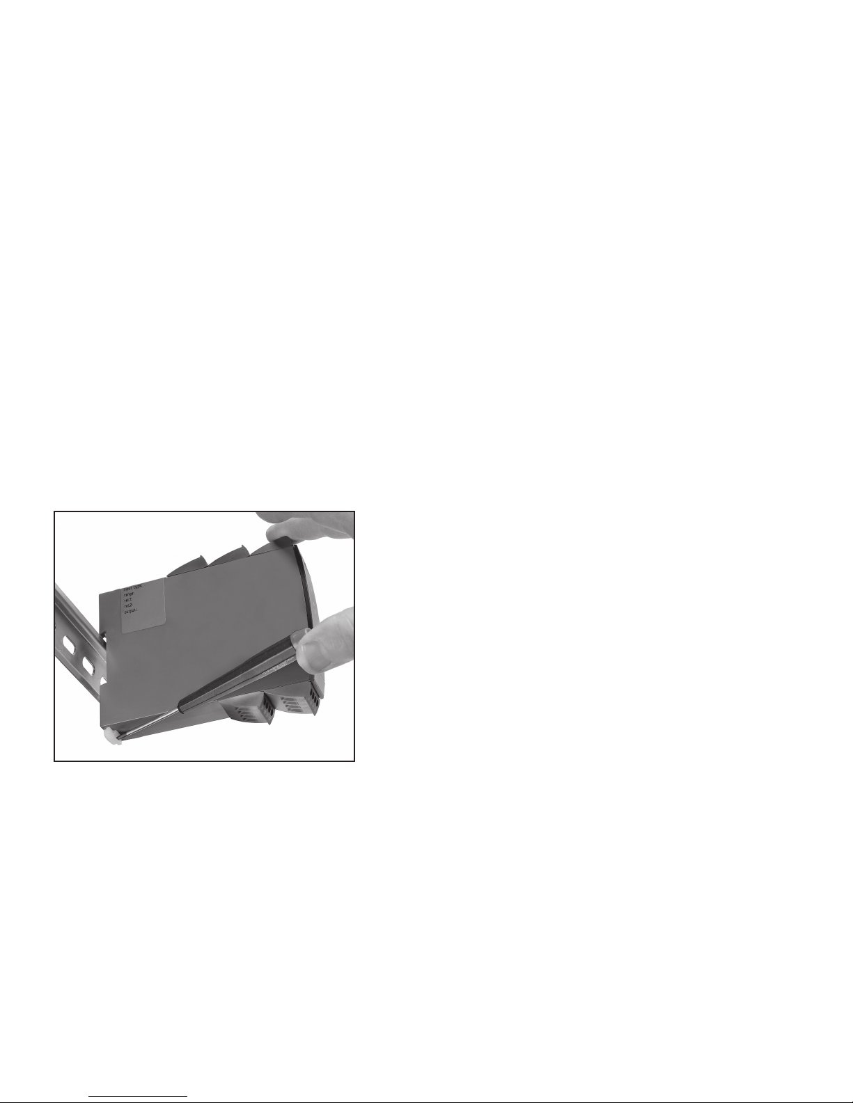
How to demount system 5000
First, remember to demount the connectors with hazardous voltages.
Picture 1:
By lifting the bottom lock, the device is detached from the DIN rail.
Calibration and adjustment
During calibration and adjustment, the measuring and connection of external voltages must be carried out according to the
specifications of this manual. The technician must use tools and instruments that are safe to use.
Normal operation
Operators are only allowed to adjust and operate devices that are safely fixed in panels, etc., thus avoiding the danger of
personal injury and damage. This means there is no electrical shock hazard, and the device is easily accessible.
Cleaning
When disconnected, the device may be cleaned with a cloth moistened with distilled water.
Liability
To the extent the instructions in this manual are not strictly observed, the custom er cannot advance a demand against PR
electronics A/S that would otherwise exist according to the concluded sales agreement.
Page 7
33
32
31
14
13
12
11
24
23
22
21
mA
mA
V V
mA
44
43
42
41
54
53
52
51
4 3 2
+
-
+
-
+
-
+
-
+
-
+
-
+
-
+
-
+
-
5116V104-UK 7
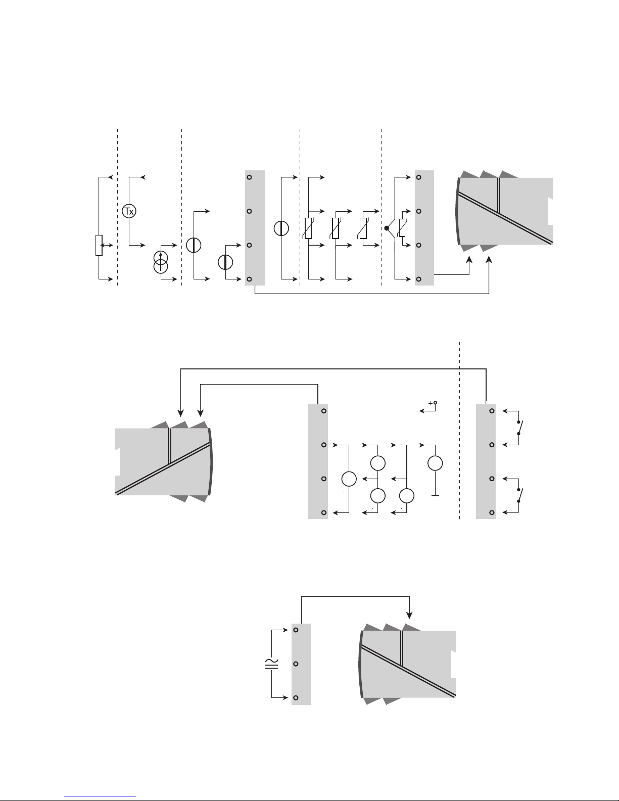
Applications
Input signals:
Current Voltage
Potentiometer
RTD and lin. R TC
Connection, wires
V<=
2.5 V
2-wire
transmitter
V>
2.5 V
Bipolar
mV
Supply:
21.6...253 VAC
or
19.2...300 VDC
Output signals:
Relays
Analog, 0/4...20 mA and voltage
2-wire transmitter output
Page 8

8 5116V104-UK
Programmable transmitter
5116
• Input for RTD, TC, mV, Ohm, potmeter, mA and V
• 2-wire supply > 16.5 V
• Bipolar voltage input
• Output for current, voltage and 2 relays
• Universal AC or DC supply
Application
• Linearised, electronic temperature measurement with RTD or TC sensor.
• Conversion of linear resistance variation to a standard analog current / voltage signal, i.e. from solenoids and butterfly
valves or linear movements with attached potentiometer.
• Power supply and signal isolator for 2-wire transmitters.
• Process control with 2 potential-free relay contacts which can be configured for advanced functions.
• Galvanic separation of analog signals and measurement of floating signals.
Technical characteristics
• Within a few seconds the user can program PR5116 to suit the specific application.
• By way of the front push-button the input can be calibrated to the exact span of the process. Zero drift on the process
signal can be adjusted by a single press of the front buttton.
• Continuous check of vital stored data for safety reasons.
• 3-port 3.75 kVAC galvanic isolation.
Mounting / installation
• Mounted vertically or horizontally on a DIN rail. As the devices can be mounted without any distance between
neighbouring units, up to 42 devices can be mounted per metre.
Page 9

5116V104-UK 9
Electrical specifications
Environmental conditions:
Operating temperature . . . . . . . . . . . . . . . . . . . . . . . . . . . . . . . . -20°C to +60°C
Calibration temperature. . . . . . . . . . . . . . . . . . . . . . . . . . . . . . . . 20...28°C
Relative humidity . . . . . . . . . . . . . . . . . . . . . . . . . . . . . . . . . . . < 95% RH (non-cond.)
Protection degree . . . . . . . . . . . . . . . . . . . . . . . . . . . . . . . . . . . IP20
Mechanical specifications:
Dimensions (HxWxD) . . . . . . . . . . . . . . . . . . . . . . . . . . . . . . . . . 109 x 23.5 x 130 mm
Weight approx. . . . . . . . . . . . . . . . . . . . . . . . . . . . . . . . . . . . . . 235 g
DIN rail type. . . . . . . . . . . . . . . . . . . . . . . . . . . . . . . . . . . . . . . DIN 46277
Wire size (min....max.) . . . . . . . . . . . . . . . . . . . . . . . . . . . . . . . . . 0.13...2.08 mm
2
AWG 26...14 stranded wire
Screw terminal torque. . . . . . . . . . . . . . . . . . . . . . . . . . . . . . . . . 0.5 Nm
Vibration. . . . . . . . . . . . . . . . . . . . . . . . . . . . . . . . . . . . . . . . . IEC 60068-2-6
2...13.2 Hz . . . . . . . . . . . . . . . . . . . . . . . . . . . . . . . . . . . . . . ±1 mm
13.2...100 Hz . . . . . . . . . . . . . . . . . . . . . . . . . . . . . . . . . . . . . ±0.7 g
Common electrical specifications:
Supply voltage . . . . . . . . . . . . . . . . . . . . . . . . . . . . . . . . . . . . . 21.6...253 VAC, 50...60 Hz
or 19.2...300 VDCC
Fuse . . . . . . . . . . . . . . . . . . . . . . . . . . . . . . . . . . . . . . . . . . . 400 mA SB / 250 VAC
Max. required power. . . . . . . . . . . . . . . . . . . . . . . . . . . . . . . . . . 2.4 W
Max. power dissipation . . . . . . . . . . . . . . . . . . . . . . . . . . . . . . . . 2.0 W
Max. required power is the maximum power needed at terminals 31 and 33.
Max. power dissipation is the maximum power dissipated by the device.
Isolation voltage, test / operation. . . . . . . . . . . . . . . . . . . . . . . . . . 3.75 kVAC / 250 VAC
PELV/SELV. . . . . . . . . . . . . . . . . . . . . . . . . . . . . . . . . . . . . . . . IEC 61140
Communications interface . . . . . . . . . . . . . . . . . . . . . . . . . . . . . . Loop Link
Signal / noise ratio. . . . . . . . . . . . . . . . . . . . . . . . . . . . . . . . . . . Min. 60 dB (0...100 kHz)
Updating time:
Temperature / ±mV input. . . . . . . . . . . . . . . . . . . . . . . . . . . . . . 115 ms
mA / V / mV input . . . . . . . . . . . . . . . . . . . . . . . . . . . . . . . . . . 75 ms
Response time (0...90%, 100...10%), programmable:
Temperature / ± mV input . . . . . . . . . . . . . . . . . . . . . . . . . . . . . 400 ms to 60 s
mA / V / mV input . . . . . . . . . . . . . . . . . . . . . . . . . . . . . . . . . . 250 ms to 60 s
Signal dynamics, input . . . . . . . . . . . . . . . . . . . . . . . . . . . . . . . . 22 bit
Signal dynamics, output . . . . . . . . . . . . . . . . . . . . . . . . . . . . . . . 16 bit
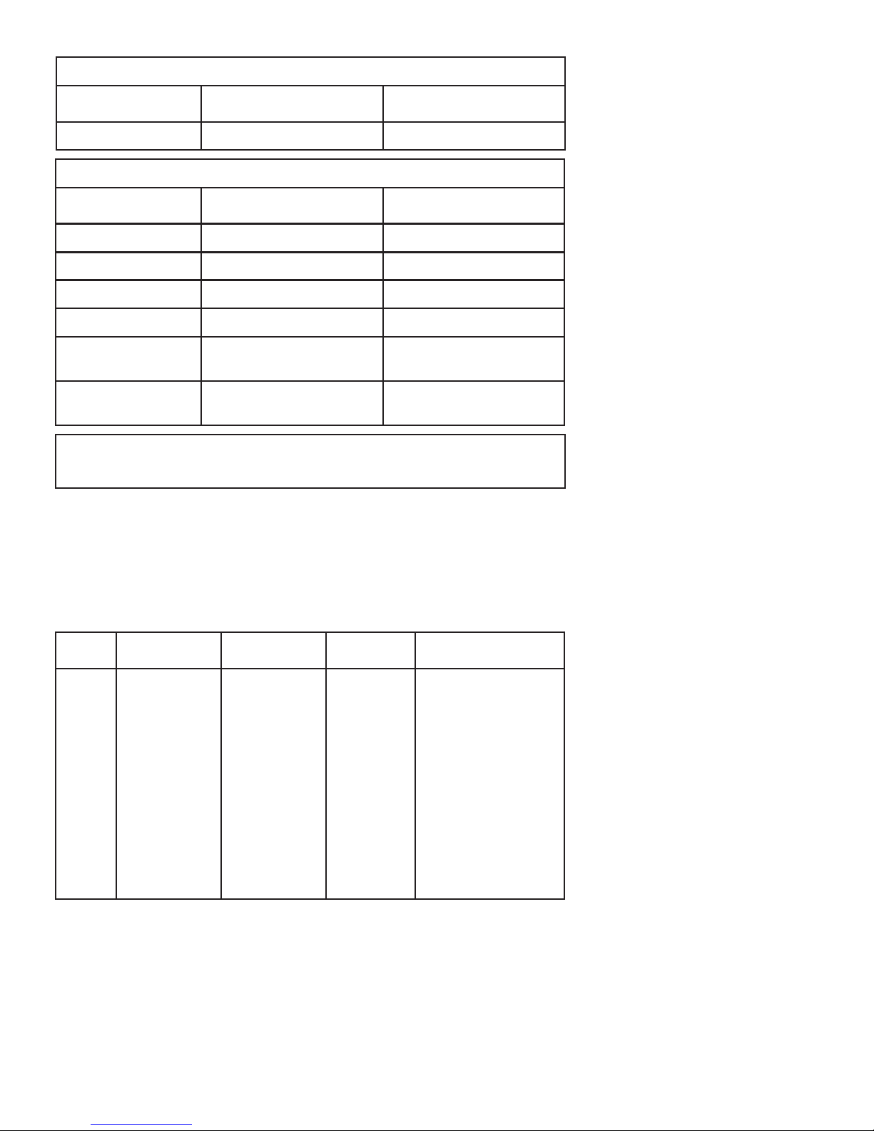
Order
Example : 5116B
NB! Please remember to order CJC connectors
type 5910/5910Ex for TC inputs with internal CJC.
Type Version
5116 Standard
ATEX Ex and FM
: A
: B
Page 10
10 5116V104-UK
Accuracy, the greater of the general and basic values:
Auxiliary supplies:
Reference voltage . . . . . . . . . . . . . . . . . . . . . . . . . . . . . . . . . . . 2.5 VDC ±0.5% / 15 mA
2-wire supply ( pin 54...52). . . . . . . . . . . . . . . . . . . . . . . . . . . . . . 28...16.5 VDC / 0...20 mA
Electrical specifications, temperature input,
terminal 41, 42, 43 and 44
Max. oset . . . . . . . . . . . . . . . . . . . . . . . . . . . . . . . . . . . . . . . 50% of selected max. value
TC input:
Sensor error current . . . . . . . . . . . . . . . . . . . . . . . . . . . . . . . . . . Nom. 30 µA
CJC . . . . . . . . . . . . . . . . . . . . . . . . . . . . . . . . . . . . . . . . . . . . < ±1°C
Sensor error detection . . . . . . . . . . . . . . . . . . . . . . . . . . . . . . . . Yes
EMC - immunity influence. . . . . . . . . . . . . . . . . . . . . . . . . < ±0.5% of span
Extended EMC immunity:
NAMUR NE 21, A criterion, burst . . . . . . . . . . . . . . . . . . . . < ±1% of span
General values
Input type Absolute accuracy Temperature coecient
All ≤ ±0.05% of span ≤ ±0.01% of span / °C
Basic values
Input type Basic accuracy Temperature coecient
mA ≤ ±4 μA ≤ ±0.4 μA / °C
Volt ≤ ±10 μV ≤ ±1 μV / °C
RTD ≤ ±0.2°C ≤ ±0.01°C / °C
Lin. R ≤ ±0.1°Ω ≤ ±10 mΩ / °C
TC type:
E, J, K, L, N, T, U
≤ ±1°C
≤ ±0.05°C / °C
TC type: B, R, S,
W3, W5, LR
≤ ±2°C
≤ ±0.2°C / °C
Type Min. value Max. value Min. span Standard
B
E
J
K
L
N
R
S
T
U
W3
W5
LR
+400°C
-100°C
-100°C
-180°C
-100°C
-180°C
-50°C
-50°C
-200°C
-200°C
0°C
0°C
-200°C
+1820°C
+1000°C
+1200°C
+1372°C
+900°C
+1300°C
+1760°C
+1760°C
+400°C
+600°C
+2300°C
+2300°C
+800°C
200°C
50°C
50°C
50°C
50°C
100°C
200°C
200°C
50°C
75°C
200°C
200°C
50°C
IEC 60584-1
IEC 60584-1
IEC 60584-1
IEC 60584-1
DIN 43710
IEC 60584-1
IEC 60584-1
IEC 60584-1
IEC 60584-1
DIN 43710
ASTM E988-90
ASTM E988-90
GOST 3044-84
Page 11

5116V104-UK 11
RTD and linear resistance input
Cable resistance per wire. . . . . . . . . . . . . . . . . . . . . . . . . . . . . . . 10 Ω
(max. 50 Ω with less accuracy)
Sensor current . . . . . . . . . . . . . . . . . . . . . . . . . . . . . . . . . . . . . Nom. 0.2 mA
Eect of sensor cable resistance (3- / 4-wire) . . . . . . . . . . . . . . . . . . < 0.002 Ω / Ω
Sensor error detection . . . . . . . . . . . . . . . . . . . . . . . . . . . . . . . . Yes
mV input:
Measurement range . . . . . . . . . . . . . . . . . . . . . . . . . . . . . . . . . . -2500...+2500 mV
Min. measurement range (span) . . . . . . . . . . . . . . . . . . . . . . . . . . . 5 mV
Input resistance . . . . . . . . . . . . . . . . . . . . . . . . . . . . . . . . . . . . > 5 MΩ
Electrical specifications, mA / V input,
terminal 51, 52, 53 and 54
Max. oset . . . . . . . . . . . . . . . . . . . . . . . . . . . . . . . . . . . . . . . 50% of selected max. value
Current input:
Measurement range . . . . . . . . . . . . . . . . . . . . . . . . . . . . . . . . . . 0...100 mA
Min. measurement range (span) . . . . . . . . . . . . . . . . . . . . . . . . . . . 4 mA
Input resistance:
Supplied unit . . . . . . . . . . . . . . . . . . . . . . . . . . . . . . . . . . . . . Nom. 10 Ω + PTC 10 Ω
Non-supplied unit . . . . . . . . . . . . . . . . . . . . . . . . . . . . . . . . . . RSHUNT = ∞, VDROP < 6 V
Sensor error detection:
loop error on 4...20 mA signals . . . . . . . . . . . . . . . . . . . . . . . . . . Yes
Voltage input
Measurement range . . . . . . . . . . . . . . . . . . . . . . . . . . . . . . . . . . 0...250 VDC
Min. measurement range (span) . . . . . . . . . . . . . . . . . . . . . . . . . . . 5 mVDC
Input resistance ≤ 2.5 VDC . . . . . . . . . . . . . . . . . . . . . . . . . . . . . Nom. 10 MΩ
> 2.5 VDC . . . . . . . . . . . . . . . . . . . . . . . . . . . . . Nom. 5 MΩ
Potentiometer input via 2.5 V ref.
Potentiometer min. . . . . . . . . . . . . . . . . . . . . . . . . . . . . . . . . . . 170 Ω
Electrical specifications - output
Max. oset . . . . . . . . . . . . . . . . . . . . . . . . . . . . . . . . . . . . . . . 50% of selected max. value
Current output
Signal range. . . . . . . . . . . . . . . . . . . . . . . . . . . . . . . . . . . . . . . 0...23 mA
Min. signal range (span). . . . . . . . . . . . . . . . . . . . . . . . . . . . . . . . 10 mA
Load (max.) . . . . . . . . . . . . . . . . . . . . . . . . . . . . . . . . . . . . . . . ≤ 600 Ω
Load stability . . . . . . . . . . . . . . . . . . . . . . . . . . . . . . . . . . . . . . ≤ 0.01% of span / 100 Ω
Current limit. . . . . . . . . . . . . . . . . . . . . . . . . . . . . . . . . . . . . . . ≤ 28 mA
Voltage output
Signal range. . . . . . . . . . . . . . . . . . . . . . . . . . . . . . . . . . . . . . . 0...10 VDC
Min. signal range (span). . . . . . . . . . . . . . . . . . . . . . . . . . . . . . . . 500 mV
Load (min.) . . . . . . . . . . . . . . . . . . . . . . . . . . . . . . . . . . . . . . . 500 kΩ
2-wire 4...20 mA output
Signal range. . . . . . . . . . . . . . . . . . . . . . . . . . . . . . . . . . . . . . . 4...20 mA
Load stability . . . . . . . . . . . . . . . . . . . . . . . . . . . . . . . . . . . . . . ≤ 0.01% of span / 100 Ω
Load resistance. . . . . . . . . . . . . . . . . . . . . . . . . . . . . . . . . . . . . ≤ (Vsupply-3.5) / 0.023 A [Ω]
Max. external 2-wire supply . . . . . . . . . . . . . . . . . . . . . . . . . . . . . 29 VDC
Eect of external 2-wire supply voltage variation . . . . . . . . . . . . . . . . < 0.005% of span / V
Input type Min. value Max. value Min. span Standard
Pt100
Ni100
Linear resist.
-200°C
-60°C
0 Ω
+850°C
+250°C
5000 Ω
25°C
25°C
30 Ω
IEC 60751
DIN 43760
-
Page 12
12 5116V104-UK
Sensor error detection and loop error on 4...20 mA
Programmable . . . . . . . . . . . . . . . . . . . . . . . . . . . . . . . . . . . . . 0...23 mA
NAMUR NE43 Upscale . . . . . . . . . . . . . . . . . . . . . . . . . . . . . . . . 23 mA
NAMUR NE43 Downscale. . . . . . . . . . . . . . . . . . . . . . . . . . . . . . . 3.5 mA
Relay outputs
Sensor error detection . . . . . . . . . . . . . . . . . . . . . . . . . . . . . . . . Break / Make / Hold / None
Max. voltage . . . . . . . . . . . . . . . . . . . . . . . . . . . . . . . . . . . . . . 250 VAC / VDC
Max. AC current. . . . . . . . . . . . . . . . . . . . . . . . . . . . . . . . . . . . . 2 A
Max. AC power . . . . . . . . . . . . . . . . . . . . . . . . . . . . . . . . . . . . . 500 VA
Max. DC current, resistive load:
@ U
relay
≤ 30 VDC . . . . . . . . . . . . . . . . . . . . . . . . . . . . . . . . . . 2 ADC
@ U
relay
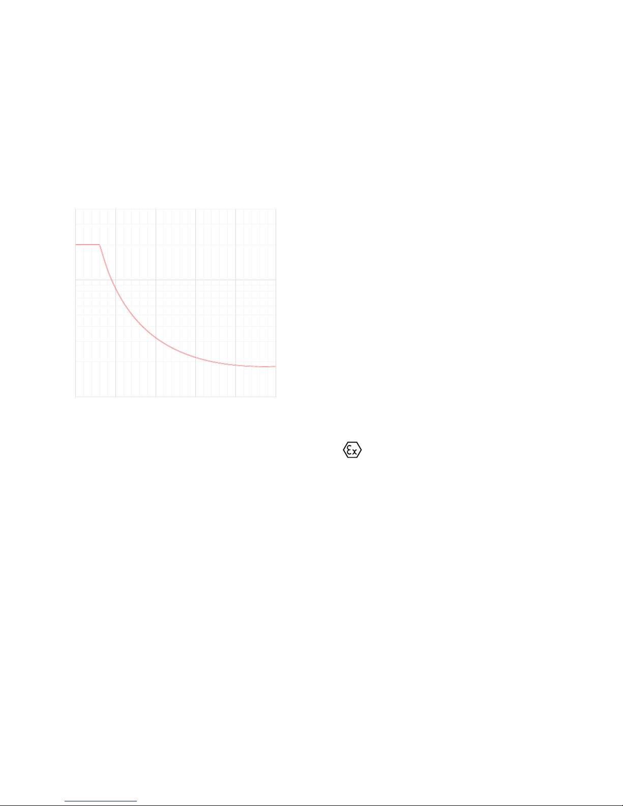
>30 VDC. . . . . . . . . . . . . . . . . . . . . . . . . . . . . . . . . . . [1380 x U
-2
relay
x 1.0085
U
relay
] ADC
Graphic depiction of [1380 x U
-2
relay
x 1.0085
U
relay
]:
Ex / I.S. approval - 5116B
KEMA 04ATEX1316 X. . . . . . . . . . . . . . . . . . . . . . . . . . . . . . . . . II (1) G [Ex ia Ga] IIC/IIB/IIA or
II (1) D [Ex ia Da] IIIC
Applicable for zone . . . . . . . . . . . . . . . . . . . . . . . . . . . . . . . . . . 0, 1, 2, 20, 21 or 22
Ex / I.S. data for 5116B
U
m
. . . . . . . . . . . . . . . . . . . . . . . . . . . . . . . . . . . . . . . . . . . . : 253 VDC
U
m
, Loop Link. . . . . . . . . . . . . . . . . . . . . . . . . . . . . . . . . . . . . . : 60 VDC
Ex / I.S. data for temperature / bipolar mV input
Terminal 41, 42, 44 and 43
U
o
. . . . . . . . . . . . . . . . . . . . . . . . . . . . . . . . . . . . . . . . . . . . . : 7.5 V
I
o
. . . . . . . . . . . . . . . . . . . . . . . . . . . . . . . . . . . . . . . . . . . . . : 2.2 mA
P
o
. . . . . . . . . . . . . . . . . . . . . . . . . . . . . . . . . . . . . . . . . . . . . : 4.2 mW
C
o
. . . . . . . . . . . . . . . . . . . . . . . . . . . . . . . . . . . . . . . . . . . . . : 6 μF
L
o
. . . . . . . . . . . . . . . . . . . . . . . . . . . . . . . . . . . . . . . . . . . . . : 1.0 H
Ex / I.S. data for unipolar mA / V input:
Terminal 51, 52 and 53
U
o
. . . . . . . . . . . . . . . . . . . . . . . . . . . . . . . . . . . . . . . . . . . . . : 7.5 V
I
o
. . . . . . . . . . . . . . . . . . . . . . . . . . . . . . . . . . . . . . . . . . . . . : 2.2 mA
P
o
. . . . . . . . . . . . . . . . . . . . . . . . . . . . . . . . . . . . . . . . . . . . . : 4.2 mW
C
o
. . . . . . . . . . . . . . . . . . . . . . . . . . . . . . . . . . . . . . . . . . . . . : 6 μF
L
o
. . . . . . . . . . . . . . . . . . . . . . . . . . . . . . . . . . . . . . . . . . . . . : 1.0 H
U
relay
50 1500 100 200 250
Current
0.10 A
0.40 A
0.80 A
0.20 A
1.00 A
0.60 A
2.00 A
3.00 A
VDC
Page 13

5116V104-UK 13
Ex / I.S. data when using 2-wire supply / reference voltage
Terminal 51, 52, 53 and 54
U
o
. . . . . . . . . . . . . . . . . . . . . . . . . . . . . . . . . . . . . . . . . . . . . : 28 V
I
o
. . . . . . . . . . . . . . . . . . . . . . . . . . . . . . . . . . . . . . . . . . . . . : 93 mA
P
o
. . . . . . . . . . . . . . . . . . . . . . . . . . . . . . . . . . . . . . . . . . . . . : 650 mW
Observed authority requirements:
EMC. . . . . . . . . . . . . . . . . . . . . . . . . . . . . . . . . . . . . . . . . . . . 2014/30/EU
LVD . . . . . . . . . . . . . . . . . . . . . . . . . . . . . . . . . . . . . . . . . . . . 2014/35/EU
RoHS . . . . . . . . . . . . . . . . . . . . . . . . . . . . . . . . . . . . . . . . . . . 2011/65/EU
Approvals
Det Norske Veritas, Ships & Oshore. . . . . . . . . . . . . . . . . . . . . . . . Standard for Certification No. 2.4
UL, Standard for Safety . . . . . . . . . . . . . . . . . . . . . . . . . . . . . . . . UL 508
EAC . . . . . . . . . . . . . . . . . . . . . . . . . . . . . . . . . . . . . . . . . . . . TR-CU 020/2011
I.S. / Ex
ATEX 2014/34/EU . . . . . . . . . . . . . . . . . . . . . . . . . . . . . . . . . . KEMA 04ATEX1316 X
FM . . . . . . . . . . . . . . . . . . . . . . . . . . . . . . . . . . . . . . . . . . . . 3023092
EAC Ex TR-CU 012/2011 . . . . . . . . . . . . . . . . . . . . . . . . . . . . . . . RU C-DK.GB08.V.00410
IIC IIB / IIIC IIA
Co: 75 nF 645 nF 2 μF
Lo: 3 mH 16 mH 31 mH
Page 14
14 5116V104-UK
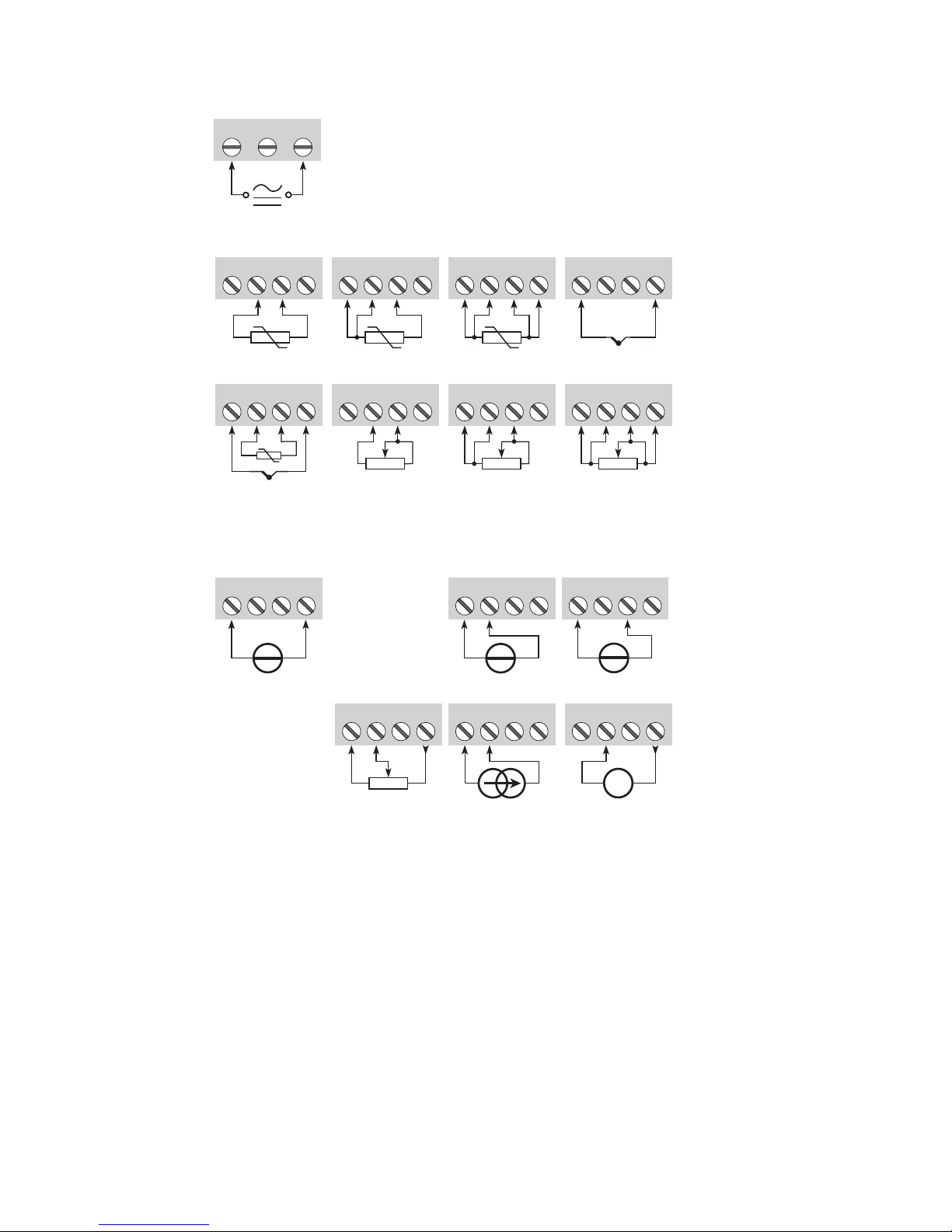
Connections
41 42 44
43
42
44
43
41 41 42 44
43
41 42 44
43
+
-
41 42 444341 42 444341 42 44
43
41 42 44
CJC
+
-
31 32
33
51 52 54
53
51 52 54
53
+
-
41 42 44
43
+
-
51 52 54
53
+
-
51 52 54
53
+
-
+
-
51 52 54
53
Tx
Current
2-wire transmitter
Potentiometer
Voltage > 2.5 V
mV
Voltage <= 2.5 V
RTD, 2-wire RTD, 3-wire RTD, 4-wire
TC, internal CJC
Resistance, 2-wire Resistance, 3-wire Resistance, 4-wire
TC, external CJC*
Inputs:
Supply:
* If the device is reconfigured from temperature measurement with CJC connector
to analogue measurement, the CJC connecter must be demounted.
Page 15

5116V104-UK 15
Connections
11 12 14
13
+
mA
11 12 14
13
+
-
mA
11 12 14
13
+
-
V
21 22 24
23
Current
2-wire installation
2 relays
R1 R2
Voltage
Outputs:
Page 16
I +
4...20 mA
V +
4 3 2
Tx
21
22
23
11
12
31
33
24
13
14
44
42
52
51
43
41
54
53
5116
EEPROM
CPU
A / D
10 W50 k
5 M
PTC
PAGMUX
50 W 500 W
mA
mA
mA
+
-
+
-
+
-
+
-
+
-
*
V V
+
-
D / A
16 5116V104-UK
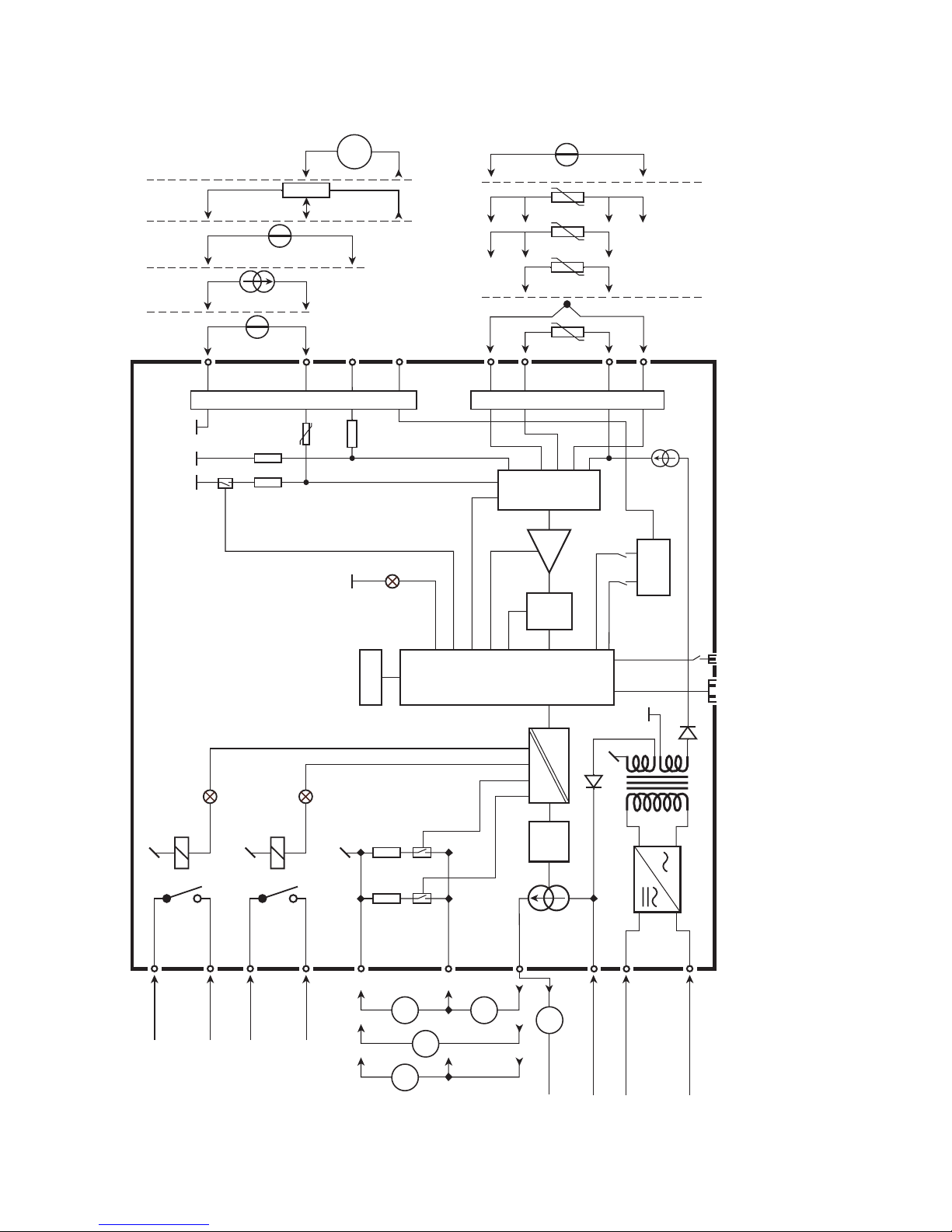
Block diagram
Supply
Supply
21.6...253 VAC or
19.2...300 VDC
Gnd.
I + V
Out.
I
Out.
V
Out.
Relay 2
Relay 2
Relay 1
Relay 1
2-wire supply +
2-wire supply -
Green
Yellow
Yellow
Electronic
contacts
Electronic
contact
2-wire
supply
RTD and lin. R,
connection,
wires
TC
Bipolar mV
2-wire supply /
2.5 V ref.
Input +,
> 2.5 V
Input +
Input gnd.
V <=
2.5 V
CurrentV >=
2.5 V
3-wire
potm.
2-wire-
transm.
Ex barrier, only 5116B Ex barrier, only 5116B
Front comm.
*
Accessories: CJC connectors type 5910 / 5910 Ex
Front button, sw 1
2.5 V
0.2 mA
V
reg.
Page 17
On
OnOn On
OnOn On
100
90
80
70
60
50
40
30
20
10
0 10 20 30 40 50 60 70 80 90 100
100
90
80
70
60
50
40
30
20
10
0 10 20 30 40 50 60 70 80 90 100
O
O O OO O
2
1
2
1
2
1
2
1
tt
100
90
80
70
60
50
40
30
20
10
0 10 20 30 40 50 60 70 80 90 100
O N.O. O N.O.On N.O.
On N.C. On N.C.
O N.C.
100
90
80
70
60
50
40
30
20
10
0 10 20 30 40 50 60 70 80 90 100
O N.O. O N.O.On N.O.
On N.C. On N.C.
O N.C.
tt
5116V104-UK 17
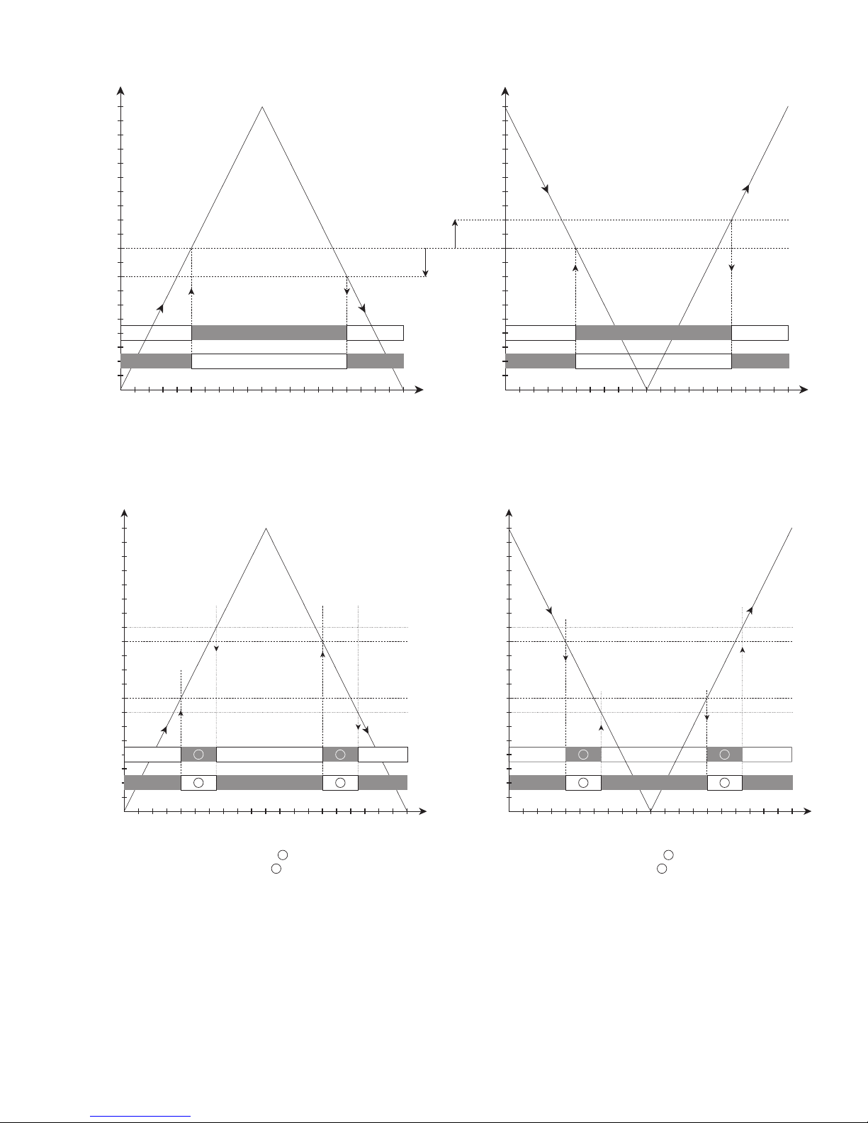
Graphic depiction of relay actions Increasing / Decreasing
Relay unitsRelay units
Setpoint = 50
Hysteresis = 10
Hysteresis = 10
Setpoint = 50
Relay units
Setpoint High = 60
Hysteresis = 5
Hysteresis = 5
Setpoint Low = 40
Relay action: Window (shown for increasing signal)
Contact: Closed inside window =
1
Contact: Open inside window = 2
Relay units
Hysteresis = 5
Hysteresis = 5
Setpoint Low = 40
Relay action: Window (shown for decreasing signal)
Contact: Closed inside window =
1
Contact: Open inside window = 2
Setpoint High = 60
Relay action: Increasing Relay action: Decreasing
Graphic depiction of relay action Window
Page 18
18 5116V104-UK
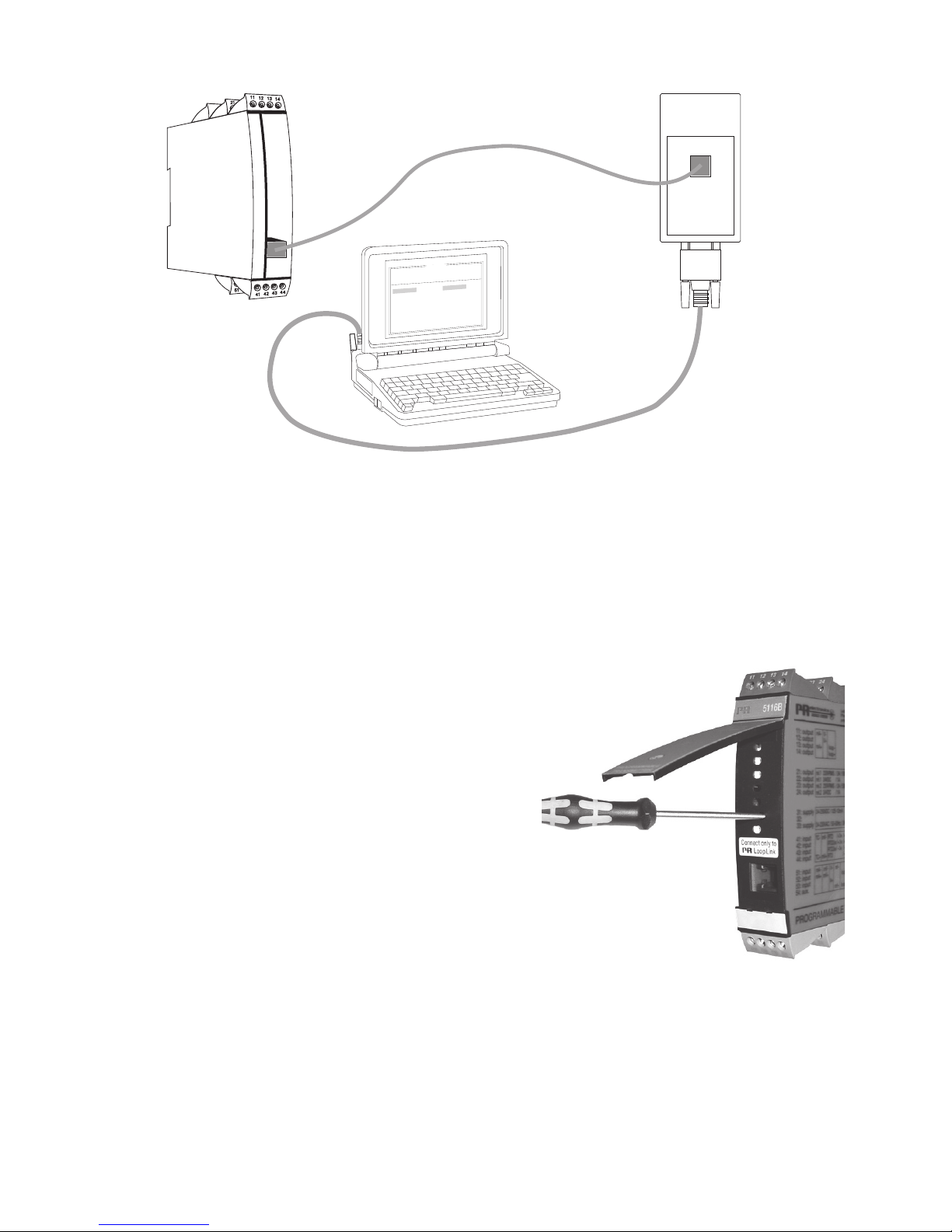
5116 connection to Loop Link
For connection of 5116B to Loop Link, please observe the instructions for instrinsically safe installation.
Activation of the process calibration button
Open the front cover and activate the switch with a pointed object, e.g. a
small screwdriver.
The switch is placed a little to the right of the LEDs.
For further instructions see the description of the process calibration
function on page 20.
F
i
l
e
P
r
o
d
u
c
t
I
n
p
u
t
O
u
t
p
u
t
C
o
m
m
u
n
i
c
a
t
i
o
n
L
a
n
g
u
a
g
e
O
p
t
i
o
n
0
8
:
3
0
:
0
0
P
R
e
t
o
p
5
3
3
1
D
a
t
e
:
1
9
9
4
-
8
-
1
0
9
4
3
2
0
1
5
9
4
P
R
e
l
e
c
t
r
o
n
i
c
s
A
n
a
l
o
g
i
n
p
u
t
A
n
a
l
o
g
o
u
t
p
u
t
S
e
r
i
a
l
n
o
:
I
n
p
u
t
t
y
p
e
:
O
u
t
p
u
t
t
y
p
e
:
4
-
2
0
m
A
U
p
s
c
a
l
e
S
e
n
s
o
r
e
r
r
o
r
:
P
t
1
0
0
D
I
N
/
I
E
C
0
.
0
0
-
5
0
.
0
0
C
3
-
w
i
r
e
1
.
0
0
s
e
c
-
-
-
-
-
-
I
n
p
u
t
r
a
n
g
e
:
C
o
n
n
e
c
t
i
o
n
:
C
o
l
d
j
u
n
c
t
i
o
n
c
o
m
p
:
R
e
s
p
o
n
s
e
t
i
m
e
:
T
a
g
n
o
:
5116
Commu-
nication
Loop Link
Page 19

5116V104-UK 19
Configuration of relay 1 & 2 in PReset
Parameter Value Description
Type
Off No relay function
Setpoint Relay changes state at a limit on the span
Setpoint window
Relay changes state inside a range of the
span
Sensor error indication Only works for sensor error
Power indication Relay is active when power is on
Relay units for Relay 1
and Relay 2
% of input span 0...100% of input span
Input units E.g. °C, mV and mA
% of output span 0...100% of output span
Output units mA and V
Setpoint From min. to max. of relay units Setpoint limit
Setpiont LOW
(setpoint window only)
From min. to max. of relay units Lower setpoint in setpoint window
Setpoint HIGH
(setpoint window only)
From min. to max. of relay units Higher setpoint in setpoint window
Hysteresis From 0.1...99.9% of relay units
Difference between setpoint value and
reset value. At setpoint window the
hysteresis is outside the window.
On-delay 0..3600 s
Time from the signal crosses the setpoint
threshold until the relay activates. Time is
reset at setpoint crossing.
Off-delay 0..3600 s
Time from the signal crosses the hysteresis
threshold until the relay deactivates. Time is
reset at hysteresis crossing.
Action
Increasing Activates at increasing signal
Decreasing Activates at decreasing signal
Contact
Normally open (N.O.) Contact state before limit is reached
Normally closed (N.C.) Contact state before limit is reached
Open inside window Energized Relay deactivated inside setpoint window
Closed inside window Relay activated inside setpoint window
Sensor error detection
Contact open Relay deactivated
Contact closed Relay activated
Hold Relay state as before sensor error occurred
Off No relay function
Page 20

20 5116V104-UK
Process calibration 0% and 100% or only 0%
(not for RTD and TC input)
When the option ”0% and 100% calibration” is actively configured in PReset it is possible to make the following process
calibrations. Please note: Input 0% and 100% should be chosen higher than the process-calibrated span.
Process calibration 0% and 100%
1. Apply the actual 0% value.
2. Open the front cover, activate sw. 1 and wait
until the green LED lights constantly.
3. Apply the actual 100% value.
4. Activate sw. 1. The LED will start flashing again.
The input on 5116 has now been scaled according to the actual process values.
When the option ”0% calibration” is actively configured in PReset it is possible to make the following process calibration.
0% process calibration
1. Apply the actual 0% value.
2. Open the front cover and activate sw. 1.
The input on 5116 has now been scaled according to the actual process values.
Error functions
Error reason
Hardware error indication
Value on analog
output
Relay contacts / Yellow LEDs Green LED
No power supply 0 mA / 0 V Contacts open / LEDs Off Constantly Off
Sensor error As configured As configured Blinking at 1...2 Hz
RAM checksum check failed *) 0 mA / 0 V Contacts open / LEDs Off Constantly On
EEPROM checksum check failed 0 mA / 0 V Contacts open / LEDs Off Constantly On
Main program stopped 0 mA / 0 V Contacts open / LEDs Off Constantly On
DAC / relay program stopped 0 mA / 0 V Contacts open / LEDs Off
Depends on
input **)
*) Error can be reset by power cycling the device or sending a new configuration.
**) The green LED is controlled by the main processor.
Page 21

Appendix
FM control drawing no. 5116QF01
5116V104-UK 21
Page 22
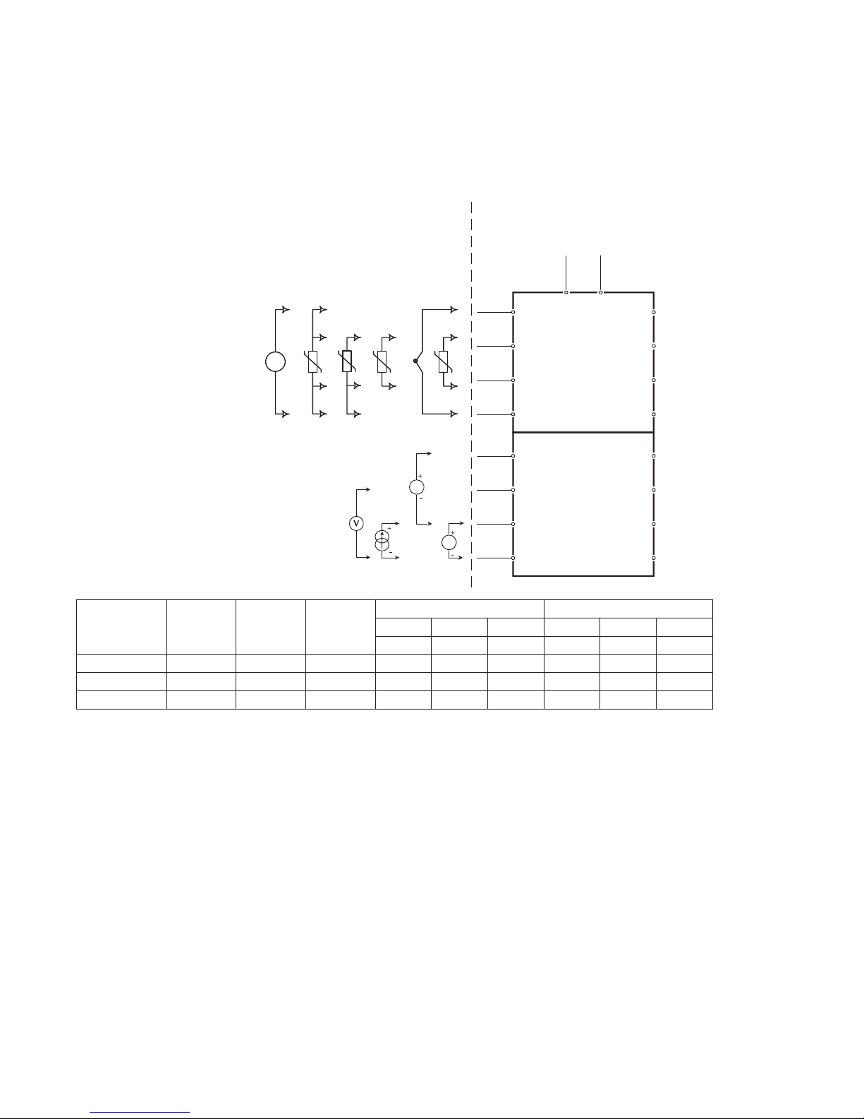
Rev. AA 2005-07-20
Control Drawing 5116QF01
La (mH)
Ca (µF)
A,B C,E D,F,G A,B C,E D,F,G
Terminal Voc (V) Isc (mA) Po (mW)
IIC IIB IIA IIC IIB IIA
41,42,43,44 7.5 2.2 4.2 1000 1000 1000 6 36 445
51,52,53 7.5 2.2 4.2 1000 1000 1000 6 36 445
51,52,53,54 28 93.0 650 3 16 31 0.075 0.645 2
Hazardous (Classified) Location Unclassified Location
or
Class I, Division 1, Group A,B,C,D
Class II, Division 1 Group E, F, G
Class III, Division 1
Class I , Zone 0 and 1, Group IIC, IIB, IIA
Class II, Zone 20 and 21
Installation notes:
1) The maximum non hazardous location voltage is 250Vac/dc.
2) The installation shall be in accordance with the National Electrical Code NFPA 70, Articles
504 and 505.
3) 5116B is galvanic isolated and does not require grounding
4) For Installation in Div 2 or Zone 2 the 5116B must be installed in an enclosure according to
ANSI/ISA S82.
5) Install in Pollution degree 2 or better
6) Use 60 / 75 °C Copper Conductors with Wire Size AWG: (26 – 14).
7) Warning: Substitution of components may impair intrinsic safety.
Simple Apparatus or
Intrinsically safe apparatus
with entity parameters:
Vmax (Ui) ≥ Vt (Uo)
Imax (Ii) ≥ It (Io)
Pi ≥ Po
Ca ≥ C
cable
+ Ci
La ≥ L
cable
+ Li
The sum of capacitance and
inductance of cable and
intrinsic safe equipment must
be less or equal to Ca and La
Hazardous (Classified) Location
Class I, Division 2, Group A,B,C,D
Class I , Zone 2, Group IIC, IIB, IIA
44
43
42
41
54
53
52
51
5116B
24
11
12
13
14
3331
21
22
23
Supply
Supply
24....230VAC &
24....230VDC
+
-
V
T
+
-
mV
+
-
22 5116V104-UK
Page 23

We are near you,
all over the world
All our devices are backed by expert service and a 5-year
warranty. With each product you purchase, you receive
personal technical support and guidance, day-to-day
delivery, repair without charge within the warranty period
and easily accessible documentation.
We are headquartered in Denmark, and have offices and
authorized partners the world over. We are a local
business with a global reach. This means that we are
always nearby and know your local markets well.
We are committed to your satisfaction and provide
PERFORMANCE MADE SMARTER all around the world.
For more information on our warranty program, or to
meet with a sales representative in your region, visit
prelectronics.com.
Our trusted red boxes are supported wherever you are
Page 24

PR electronics is the leading technology company specialized in making industrial process
control safer, more reliable and more efficient. Since 1974, we have been dedicated to
perfecting our core competence of innovating high precision technology with low power
consumption. This dedication continues to set new standards for products communicating,
monitoring and connecting our customers’ process measurement points to their process
control systems.
Our innovative, patented technologies are derived from our extensive R&D facilities and
from having a great understanding of our customers’ needs and processes. We are guided
by principles of simplicity, focus, courage and excellence, enabling some of the world’s
greatest companies to achieve PERFORMANCE MADE SMARTER.
Benefit today from
PERFORMANCE MADE SMARTER
www.prelectronics.com
 Loading...