

Page 1
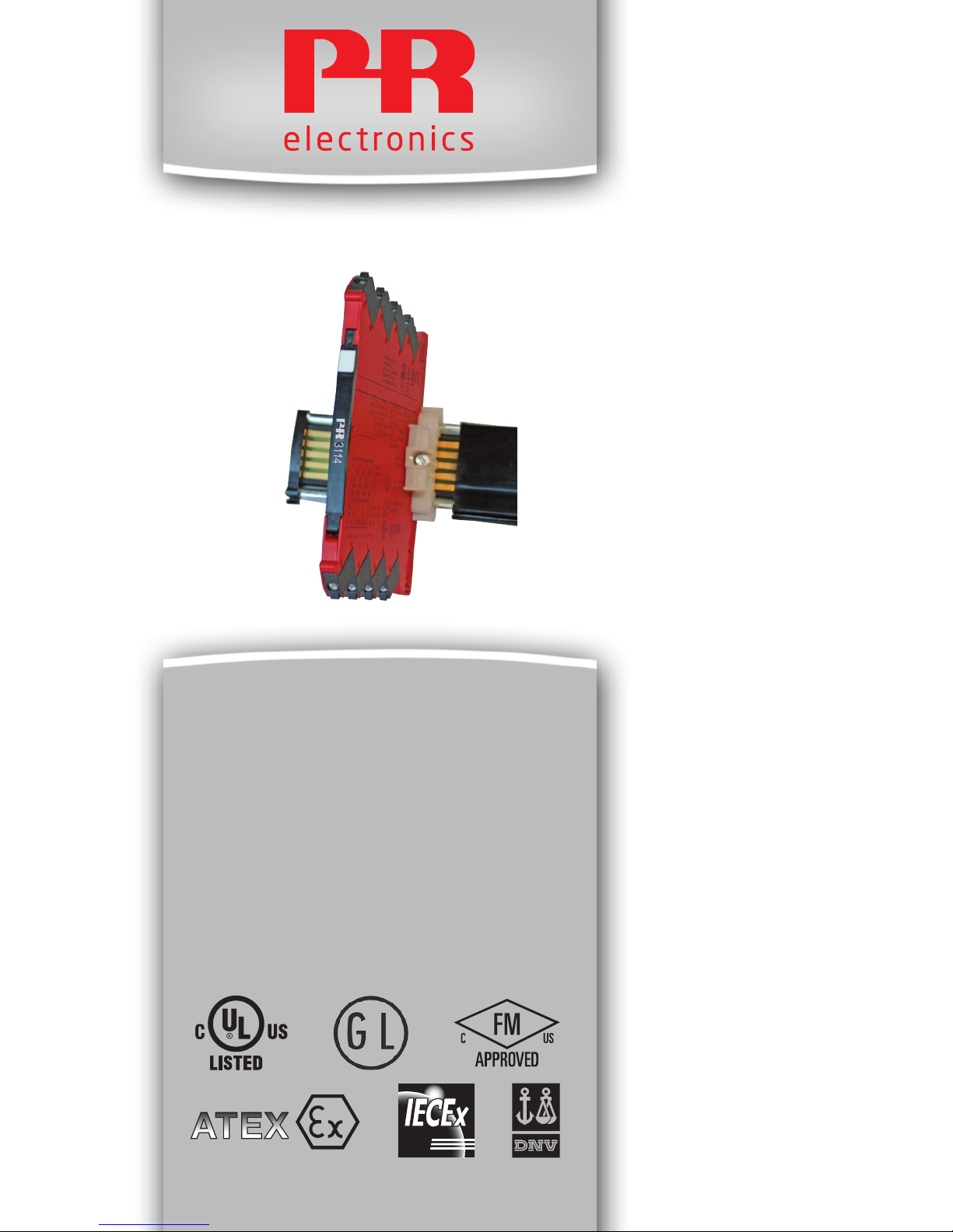
3114
Isolated Universal
Converter
No. 3114V101-UK
Page 2

PR electronics A/S tilbyder et bredt program af analoge og digitale
signalbehandlingsmoduler til industriel automation. Programmet
består af Isolatorer, Displays, Ex-barrierer, Temperaturtransmittere,
Universaltransmittere m. Vi har modulerne, du kan stole på i selv
barske miljøer med elektrisk støj, vibrationer og temperaturudsving, og alle produkter opfylder de strengeste internationale standarder. Vores motto »Signals the Best« er indbegrebet af denne
loso – og din garanti for kvalitet.
PR electronics A/S offers a wide range of analogue and digital
signal conditioning devices for industrial automation. The product
range includes Isolators, Displays, Ex Interfaces, Temperature
Transmitters, and Multifunctional Devices. You can trust our
products in the most extreme environments with electrical noise,
vibrations and temperature uctuations, and all products comply
with the most exacting international standards. »Signals the Best«
is the epitome of our philosophy – and your guarantee for quality.
PR electronics A/S offre une large gamme de produits pour le
traite ment des signaux analogiques et numériques dans tous
les domaines industriels. La gamme de produits s’étend des
transmetteurs de température aux afcheurs, des isolateurs aux
interfaces SI, jusqu’aux modules universels. Vous pouvez compter
sur nos produits même dans les conditions d’utilisation sévères,
p.ex. bruit électrique, vibrations et uctuations de température.
Tous nos produits sont conformes aux normes internationales les
plus strictes. Notre devise »SIGNALS the BEST« c’est notre ligne
de conduite - et pour vous l’assurance de la meilleure qualité.
PR electronics A/S verfügt über ein breites Produktprogramm
an analogen und digitalen Signalverarbeitungsgeräte für die industrielle Automatisierung. Dieses Programm umfasst Displays,
Temperaturtransmitter, Ex- und galvanische Signaltrenner, und
Universalgeräte. Sie können unsere Geräte auch unter extremen
Einsatzbedingungen wie elektrisches Rauschen, Erschütterungen
und Temperaturschwingungen vertrauen, und alle Produkte von
PR electronics werden in Überein stimmung mit den strengsten
internationalen Normen produziert. »Signals the Best« ist Ihre
Garantie für Qualität!
DK
UK
FR
DE
1337
Page 3

3114V101-UK 1
ISOLATED UNIVERSAL CONVERTER
3114
CONTENTS
Warning .......................................................................................... 2
Safety instructions .......................................................................... 4
UL installation ............................................................................ 4
cFMus installation in Division 2 or Zone 2 ................................ 5
IECEx, ATEX installation in Zone 2 ............................................ 5
Flexible supply ............................................................................... 7
Mounting and demounting of system 3000 ................................... 8
Installation on DIN rail .................................................................... 9
Supply of power rail ....................................................................... 9
Side label ........................................................................................ 9
Highlights ....................................................................................... 10
Advanced features ......................................................................... 10
Applications .................................................................................... 10
Technical characteristics ................................................................ 10
Product overview ........................................................................... 11
PR 4501 Display / programming front ........................................... 12
ConfigMate 4590 adapter .............................................................. 13
Display readout on the 4501 of sensor error detection
and input signal outside range .................................................. 19
Sensor error detection limits .......................................................... 19
Error indications ............................................................................. 20
Connections ................................................................................... 21
Installation on power rail ................................................................ 22
Marking ........................................................................................... 23
LED indication ................................................................................ 24
Default configuration ...................................................................... 25
Configuration / operating the function keys ................................. 26
Routing diagram ............................................................................. 30
Routing diagram, Advanced settings (ADV.SET) ............................ 31
Scrolling help text in display line 3 ................................................ 32
NB.: Click on the entries in the table of contents to go to the desired section.
Page 4
2 3114V101-UK
WARNING
To avoid the risk of electric shock and fire, the safety instructions
of this manual must be observed and the guidelines fol lowed.
The specifications must not be exceeded, and the device must
only be applied as described in the following.
Prior to the commissioning of the device, this manual must be
examined carefully.
Only qualified personnel (technicians) should install this device.
If the equipment is used in a manner not specified by the
manufacturer, the protection provided by the equipment may
be impaired.
Until the device is fixed, do not connect hazardous voltages to
the device.
Repair of the device must be done by PR electronics A/S
only.
GENERAL
WARNING
In applications where hazardous voltage is connected to in-/
outputs of the device, sufficient spacing or isolation from wires,
terminals and enclosure to surroundings (incl. neighbouring
devices), must be ensured to maintain protection against electric
shock.
The connector behind the front cover of 3114 is connected to the
input terminals on which dangerous voltages can occur.
Potential electrostatic charging hazard. To avoid the risk of
explosion due to electrostatic charging of the enclosure, do
not handle the units unless the area is known to be safe, or
appropriate safety measures are taken to avoid electrostatic
discharge.
HAZARD-
OUS
VOLTAGE
CAUTION
Page 5

3114V101-UK 3
SYMBOL IDENTIFICATION
Triangle with an exclamation mark: Read the manual before installation
and commissioning of the device in order to avoid incidents that could
lead to personal injury or mechanical damage.
The CE mark proves the compliance of the device with the essential
requirements of the directives.
Ex devices have been approved according to the ATEX directive for use
in connection with installations in explosive areas.
Page 6

4 3114V101-UK
SAFETY INSTRUCTIONS
RECEIPT AND UNPACKING
Unpack the device without damaging it and check whether the device type
corresponds to the one ordered. The packing should always follow the device
until this has been permanently mounted.
ENVIRONMENT
Avoid direct sunlight, dust, high temperatures, mechanical vibrations and shock,
as well as rain and heavy moisture. If necessary, heating in excess of the stated
limits for ambient temperatures should be avoided by way of ventilation. All
devices can be used for Measurement Category II and Pollution Degree 2. The
module is designed to be safe at least under an altitude up to 2 000 m.
MOUNTING
Only technicians who are familiar with the technical terms, warnings, and
in structions in the manual and who are able to follow these should connect the
device.
Should there be any doubt as to the correct handling of the device, please
contact your local distributor or, alternatively,
PR electronics A/S
www.prelectronics.com
Mounting and connection of the device should comply with national legislation
for mounting of electric materials, i.e. wire cross section, protective fuse, and
location.
Descriptions of input / output and supply connections are shown in this manual
and on the side label.
The device is provided with field wiring terminals and shall be supplied from a
Power Supply having double / reinforced insulation. A power switch should be
easily accessible and close to the device. The power switch shall be marked as
the disconnecting unit for the device.
SYSTEM 3000 must be mounted on a DIN rail according to EN 60715.
UL INSTALLATION
Use 60/75°C copper conducters only.
Wire size ..................................................... AWG 26-12
UL file number ............................................ E314307
The device is an Open Type Listed Process Control Equipment. To prevent injury
resulting from accessability to live parts the equipment must be installed in an
enclosure.
Page 7

3114V101-UK 5
The power supply unit must comply with NEC Class 2, as described by the
National Electrical Code
®
(ANSI / NFPA 70).
cFMus INSTALLATION IN DIVISION 2 OR ZONE 2
Class I, Div. 2, Group A, B, C, D T4 or I, Zone 2, AEx nA IIC T4 or Ex nA IIC T4.
In class I, Division 2 or Zone 2 installations, the subject equipment shall be
mounted within a tool-secured enclosure which is capable of accepting one or
more of Class I, Division 2 wiring methods specified in the National Electrical
Code (ANSI/NFPA 70) or in Canada in the Canadian Electrical Code (C22.1).
The 3000 System Isolators and Converters must be connected to limited output
NEC Class 2 circuits, as outlined in the National Electrical Code
®
(ANSI /
NFPA 70), only. If the devices are connected to a redundant power supply (two
separate power supplies), both must meet this requirement.
Where installed in outdoor or potentially wet locations the enclosure shall at a
minimum meet the requirements of IP54.
Warning: Substitution of components may impair suitability for zone 2 / division 2.
Warning: To prevent ignition of the explosive atmospheres, disconnect power
before servicing and do not separate connectors when energised and an
explosive gas mixture is present.
Warning: Do not mount or remove devices from the power rail when an explosive
gas mixture is present.
IECEx, ATEX INSTALLATION IN ZONE 2
IECEx KEM 10.0068 X.......... Ex nA IIC T4 Gc
KEMA 10ATEX0147 X ........... II 3G Ex nA IIC T4 Gc
For safe installation the following must be observed. The device shall only be
installed by qualified personnel who are familiar with the national and international
laws, directives and standards that apply to this area.
Year of manufacture can be taken from the first two digits in the serial number.
The devices shall be installed in a suitable enclosure providing a degree of
protection of at least IP54 according to EN60529, taking into account the
environmental conditions under which the equipment will be used.
Page 8

6 3114V101-UK
When the temperature under rated conditions exceeds 70°C at the cable or
conduit entry point, or 80°C at the branching point of the conductors, the
temperature specification of the selected cable shall be in compliance with the
actual measured temperature.
Provisions shall be made to prevent the rated voltage from being exceeded by
transient disturbances of more than 40%.
For installation on power rail in zone 2, only Power Rail type 9400 supplied by
Power Control Unit type 9410 is allowed.
To prevent ignition of the explosive atmospheres, disconnect power before
servicing and do not separate connectors when energised and an explosive gas
mixture is present.
Do not mount or remove devices from the power rail when an explosive gas
mixture is present.
CLEANING
When disconnected, the device may be cleaned with a cloth moistened with
distilled water.
LIABILITY
To the extent the instructions in this manual are not strictly observed, the
customer cannot advance a demand against PR electronics A/S that would
otherwise exist according to the concluded sales agreement.
Page 9
3114V101-UK 7
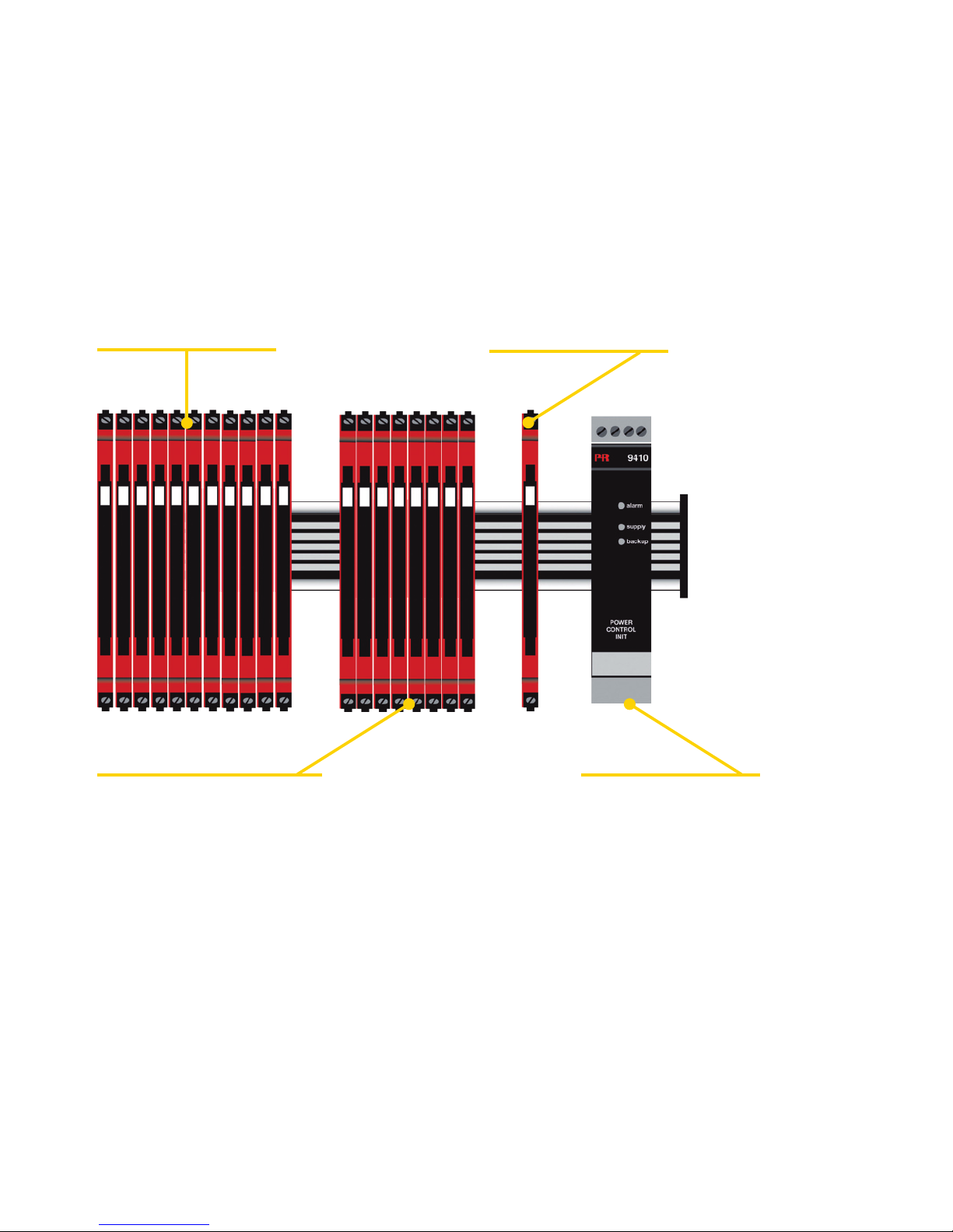
Fuse characteristics: The 2.5 A fuse must break after not more than 120 seconds
at 6.4 A.
The units can be supplied with 24
VDC±30% via direct wiring and a loop
between the devices. This permits the
supply of up to 130 units.
Protective fuse: 2.5 A.
Protective fuse: 0.4 A.
Alternatively, the 24 V supply voltage can
be distributed via a power rail that receives
the voltage from another connected unit
(3103, -04, -05, -08, -09, or -14). In this
way up to 20 units can be supplied.
Protective fuse: PR 9410.
With the power control unit
9410 redundant supply is
possible. This solution can
supply up to 200 units.
The power connector unit 3405 is a
standalone supply unit which supplies
the power rail. With 3405, up to 100
units can be supplied.
Protective fuse: 2.5 A.
FLEXIBLE SUPPLY
Page 10
8 3114V101-UK
MOUNTING AND DEMOUNTING OF SYSTEM 3000
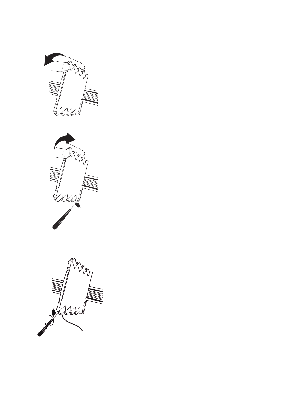
Picture 1:
Mounting on DIN rail / power rail.
Click the device onto the rail
Picture 2:
Demounting from DIN rail / power rail .
First, remember to demount the connectors with
hazardous voltages. Detach the device from the rail
by lifting the bottom lock.
Picture 3:
Wire size 0.13 x 2.5 mm
2
stranded wire.
Screw terminal torque 0.5 Nm.
Page 11
}
}
}
< 3,5 mm
> 24 mm
35 mm
3114V101-UK 9
INSTALLATION ON DIN RAIL
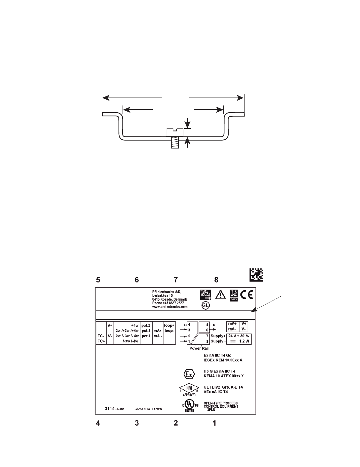
To avoid short circuit between the power rail connectors on the 3000 devices
and the screws holding the 7.5 mm DIN rail, the head of the screws shall be
no more than 3.5 mm high.
SUPPLY OF POWER RAIL
It is possible to supply the power rail via the supply terminals.
The terminals can pass a current of max. 400 mA.
SIDE LABEL
Approvals
Pin
connections
Type no.
Terminal numbers
3xxx
Page 12

10 3114V101-UK
ISOLATED UNIVERSAL CONVERTER
3114
Highlights
• Input for RTD, TC, Ohm, potentiometer, mA and V
• 2-wire supply > 15 V
• I.S. approvals: FM Div. 2, ATEX Zone 2, IECEx Zone 2
• Output for current and voltage
Advanced features
Programmable by way of detachable display front (4501) and ConfigMate 4590,
process calibration, signal simulation, password protection, error diagnostics
and help text available in several languages.
Applications
• Linearised,electronictemperaturemeasurementwithRTDorTCsensor.
• Conversion of linear resistance variation to a standard analogue current /
voltage signal, i.e. from solenoids and butterfly valves or linear movements with
attached potentiometer.
• Powersupplyandsignalisolatorfor2-wiretransmitters.
• Processcontrolwithstandardanalogueoutput.
• Galvanicseparationofanaloguesignalsandmeasurementoffloatingsignals.
Technical characteristics
• When3114isusedincombinationwiththe4501display/programmingfront
and ConfigMate 4590, all operational parameters can be modified to suit any
application. As the 3114 is designed with electronic hardware switches, it is not
necessary to open the device for setting of DIP-switches.
• AgreenfrontLEDindicatesnormaloperationandmalfunction.
• Continuouscheckofvitalstoreddataforsafetyreasons.
• 3-port2.5kVACgalvanicisolation.
Page 13

3114V101-UK 11
Product overview
PR type no. 3114
PR product name Isolated universal converter
Description
Universal DC / DC and temperature
converter with loop supply output
Parameterisation 4501 / ConfigMate 4590
Input signal
RTD, TC and potentiometer
2-, 3-, and 4-wire
0...10 V
0...20 mA
Sensor type All standard Pt, Ni, TC
CJC sensor Internal Pt100
Loop supply output
> 15 V
@ 20 mA
Output signal (active) 0...20 mA / 0...10 V
Approvals
UL, safety / FM Div. 2 / ATEX zone 2 /
IECEx Zone 2 / DNV, marine / GL, marine
Page 14
12 3114V101-UK
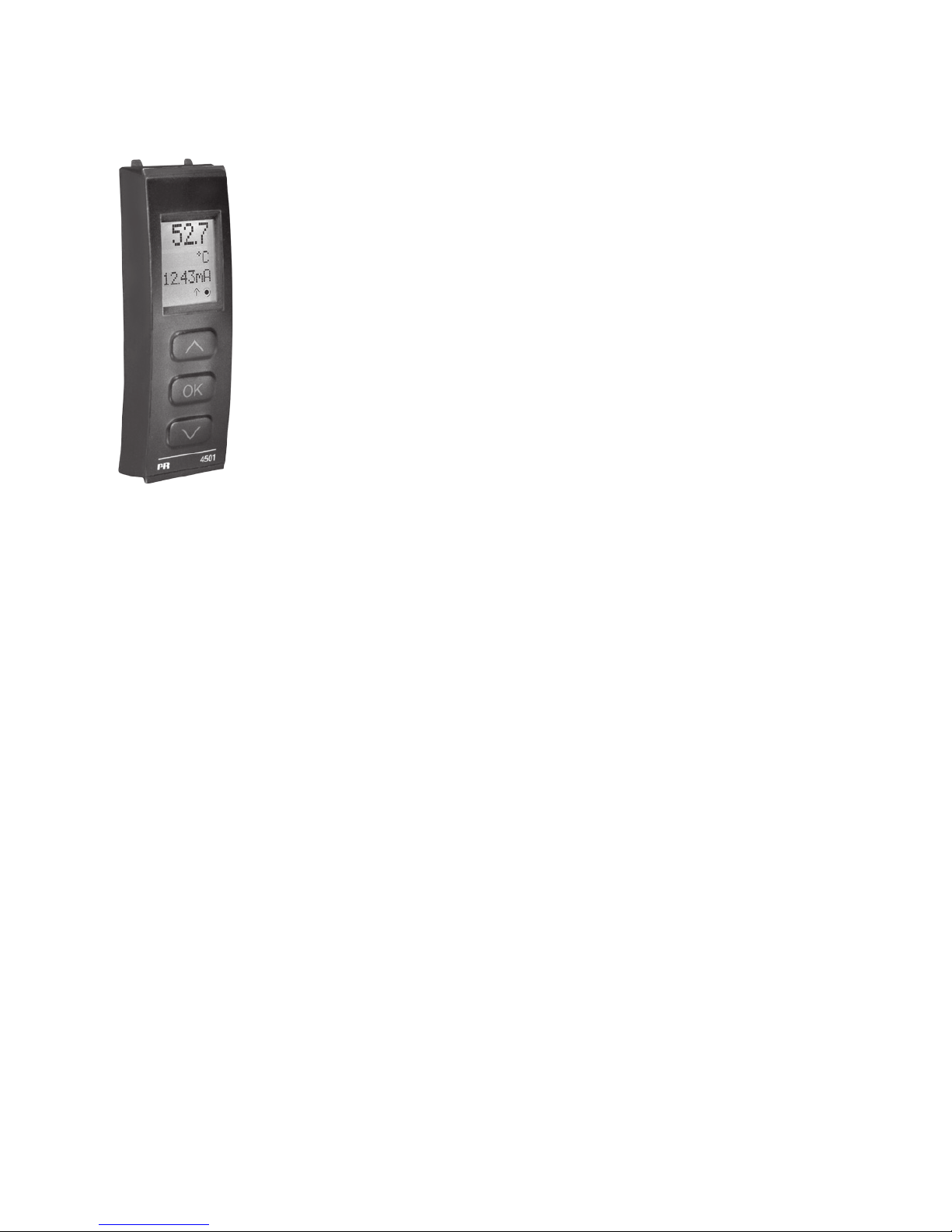
PR 4501 DISPLAY / PROGRAMMING FRONT
Functionality
The simple and easily understandable menu structure and the
explanatory help texts guide you effortlessly and automatically
through the configuration steps, thus making the product very easy
to use. Functions and configuration options are described in the
section ”Configuration /operating the function keys”.
Application
• Communicationsinterfaceformodificationofoperationalparametersin3114.
• Canbemovedfromone3114devicetoanotheranddownloadtheconfiguration
of the first device to subsequent devices.
Technical characteristics
• LCDdisplaywith4lines;Line1(H=5.57mm)showsinputsignal,line2(H=3.33
mm)showsunits,line3(H=3.33mm)showsanalogueoutputortagno.andline
4 shows communication status.
• Programmingaccesscanbeblockedbyassigningapassword.Thepassword
is saved in the device in order to ensure a high degree of protection against
unauthorised modifications to the configuration.
Mounting / installation
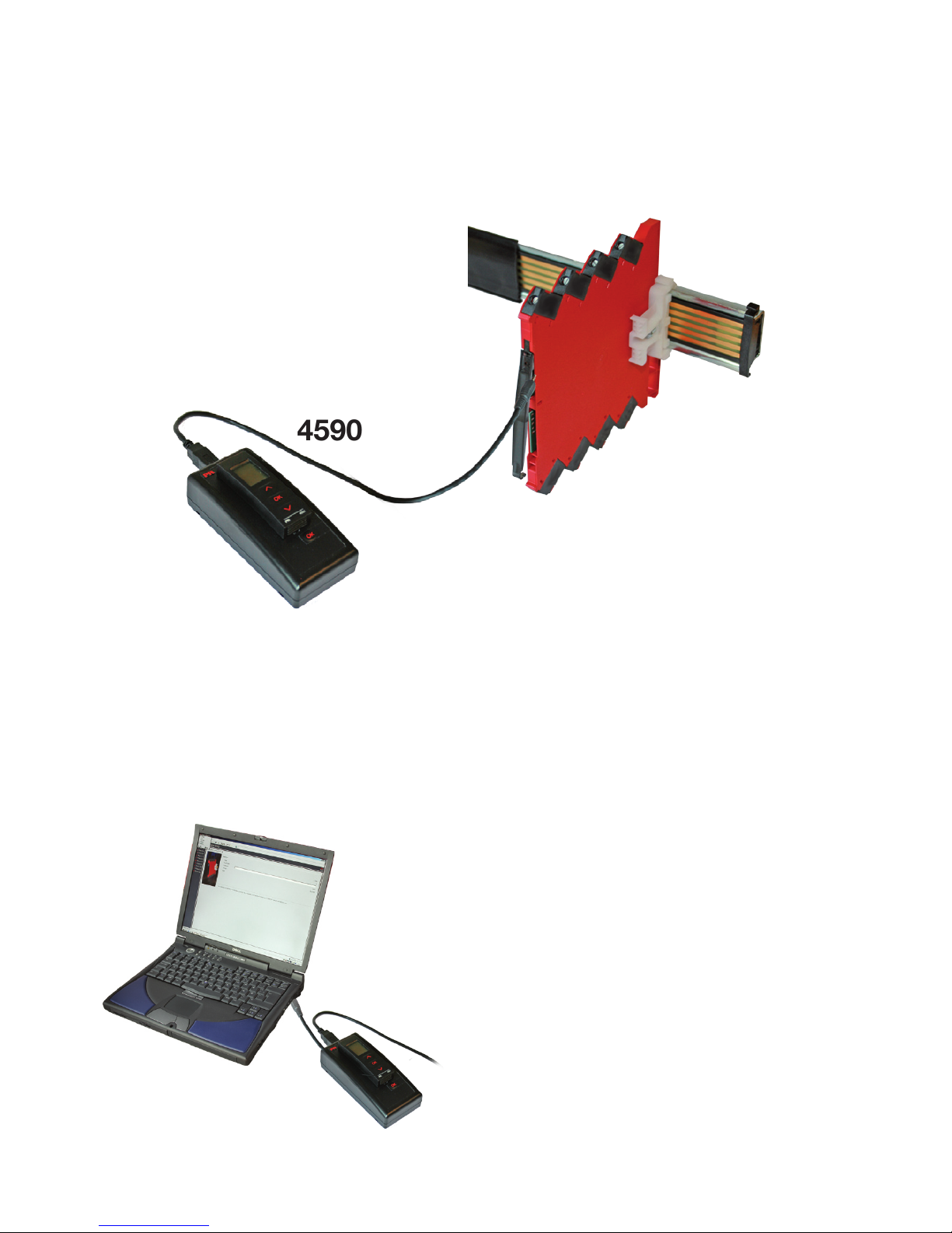
• Click4501intotheadapterConfigMate4590andconnecttheadapterto3114.
Page 15
3114
4590
3114V101-UK 13
CONFIGMATE 4590 ADAPTER
Connect the adapter by opening the front plate on 3114 and inserting the jack
into the plug.
Once configuration of the device with 4501 has been terminated, the parameters
can be transferred into the PC-based PReset program. The included USB cable
is connected between ConfigMate 4590 and the USB port of the computer and
the PC will then automatically retrieve
the necessary driver from the internet.
For further instructions regarding use of
the PReset software, please consult the
manual for PReset 5909.
Page 16

14 3114V101-UK
Order codes:
3114 = Isolated universal converter
4501 = Display / programming front
4590 = ConfigMate adapter
Electrical specifications:
Specifications range .................................... -25°C to +70°C
Common specifications:
Supply voltage, universal ............................ 16.8...31.2 VDC
Max. consumption....................................... 1.2 W
Fuse ............................................................. 400 mA SB / 250 VAC
Isolation voltage, test / working .................. 2.5 kVAC / 300 VAC / 250 VAC (Ex)
Communications interface .......................... Programming front 4501 /
ConfigMate 4590
Signal / noise ratio ...................................... Min. 60 dB (0...100 kHz)
Response time (0...90%, 100...10%):
Temperature input ................................... 1 s
mA / V input ............................................ 400 ms
Calibration temperature............................... 20...28°C
Accuracy, the greater of the general and basic values:
General values
Input
type
Absolute
accuracy
Temperature
coefficient
All ≤ ±0.1% of span ≤ ±0.01% of span / °C
Page 17

3114V101-UK 15
Auxiliary supplies:
2-wire supply (terminal 3 and 4) .................. 25...15 VDC / 0...20 mA
Max. wire size .............................................. 0.13...2.5 mm
2
stranded wire
Screw terminal torque ................................. 0.5 Nm
Relative humidity ......................................... < 95% RH (non-cond.)
Dimensions .................................................. 113 x 6.1 x 115 mm
Protection degree ........................................ IP20
Weight ......................................................... 70 g
Conducted RF/LF immunity influence ................ < ±0.5% of span
Extended EMC immunity:
ESD / HF / Burst / Surge immunity influence ..... < ±1% of span
Basic values
Input
type
Basic
accuracy
Temperature
coefficient
mA ≤ ±16 µA ≤ ±1.6 µA / °C
0...1 V & 0.2...1 V ≤ ±0.8 mV ≤ ±0.08 mV / °C
0...5 V, 1...5 V,
0...10 V & 2...10 V ≤ ±8 mV
≤ ±0.8 mV / °C
Pt100, Pt200,
Pt 1000 ≤ ±0.2°C ≤ ±0.02°C / °C
Pt500, Ni100,
Ni120, Ni 1000 ≤ ±0.3°C ≤ ±0.03°C / °C
Pt50, Pt400, Ni50 ≤ ±0.4°C ≤ ±0.04°C / °C
Pt250, Pt300 ≤ ±0.6°C ≤ ±0.06°C / °C
Pt20 ≤ ±0.8°C ≤ ±0.08°C / °C
Pt10 ≤ ±1.4°C ≤ ±0.14°C / °C
TC type:
E, J, K, L, N, T, U
≤ ±1°C
≤ ±0.1°C / °C
TC type: R, S, W3,
W5, LR
≤ ±2°C
≤ ±0.2°C / °C
TC type: B
160...400°C ≤ ±4.5°C ≤ ±0.45°C / °C
TC type: B
400...1820°C ≤ ±2°C ≤ ±0.2°C / °C
Page 18

16 3114V101-UK
RTD, linear resistance and potentiometer input:
Input for RTD types:
Pt10, Pt20, Pt50, Pt100, Pt200, Pt250, Pt300, Pt400, Pt500, Pt1000
Ni50, Ni100, Ni120, Ni1000
Cable resistance per wire (max.), RTD ........ 50 Ω
Sensor current, RTD .................................... Nom. 0.2 mA
Effect of sensor cable resistance
(3- / 4-wire), RTD ......................................... < 0.002 Ω / Ω
Sensor error detection, RTD ....................... Yes
Short circuit detection, RTD ........................ < 15 Ω
TC input:
Cold junction compensation (CJC)
via internal CJC sensor ........................... ±(2.0°C + 0.4°C * Δt)
Δt=internaltemperature-ambienttemperature
Sensor error detection, all TC types ........... Ye s
Sensor error current:
when detecting ....................................... Nom. 2 μA
else .......................................................... 0 μA
Input
type
Min.
value
Max.
value
Standard
Pt100
Ni100
Lin. R
Potentiometer
-200°C
-60°C
0 Ω
10 Ω
+850°C
+250°C
10000 Ω
100 kΩ
IEC60751
DIN 43760
-
-
Type
Min.
value
Max.
value
Standard
B
E
J
K
L
N
R
S
T
U
W3
W5
LR
0°C
-100°C
-100°C
-180°C
-200°C
-180°C
-50°C
-50°C
-200°C
-200°C
0°C
0°C
-200°C
+1820°C
+1000°C
+1200°C
+1372°C
+900°C
+1300°C
+1760°C
+1760°C
+400°C
+600°C
+2300°C
+2300°C
+800°C
IEC 60584-1
IEC 60584-1
IEC 60584-1
IEC 60584-1
DIN 43710
IEC 60584-1
IEC 60584-1
IEC 60584-1
IEC 60584-1
DIN 43710
ASTM E988-90
ASTM E988-90
GOST 3044-84
Page 19

3114V101-UK 17
Current input:
Measurement range .................................... 0...20 mA
Programmable measurement ranges .......... 0...20 and 4...20 mA
Input resistance ........................................... Nom. 20 Ω + PTC 50 Ω
Sensor error detection:
Loop break 4...20 mA.............................. Yes
Voltage input:
Measurement range .................................... 0...12 VDC
Programmable measurement ranges .......... 0...1 / 0.2...1 / 0...5 / 1...5 /
0...10 and 2...10 VDC
Input resistance ........................................... Nom. 10 MΩ
Current output:
Signal range (span) ...................................... 0...20 mA
Programmable signal ranges ...................... 0...20 / 4...20 / 20...0 / 20...4 mA
Load (max.) .................................................. 20 mA / 600 Ω / 15 VDC
Load stability ............................................... ≤ 0.01% of span / 100 Ω
Sensor error detection ................................ 0 / 3.5 / 23 mA / none
NAMUR NE 43 Upscale / Downscale ......... 23 mA / 3.5 mA
Output limitation:
on 4...20 and 20...4 mA signals .............. 3.8...20.5 mA
on 0...20 and 20...0 mA signals .............. 0...20.5 mA
Current limit ................................................. ≤ 28 mA
Voltage output:
Signal range ................................................ 0...10 VDC
Programmable signal ranges ...................... 0...1 / 0.2...1 / 0...10 / 0...5 / 1...5 /
2...10 / 1...0 / 1...0.2 / 5...0 / 5...1 /
10...0 og 10...2 V
Load (min.) ................................................... >10 kΩ
Page 20

18 3114V101-UK
Approvals
Det Norske Veritas, Ships & Offshore ......... Stand. f. Certification No. 2.4
Germanischer Lloyd .................................... V1-7-2
ATEX 94/9/EC .............................................. EN 60079-0, -15
IECEx ........................................................... IEC 60079-0, -15
cFMus .......................................................... FM 3600, 3611, 3810
CSA E60079-0, -15
CSA 22.2 -213
EMC 2004/108/EC ...................................... EN 61326-1
LVD 2006/95/EC .......................................... EN 61010-1:2001
UL, Standard for Safety .............................. UL 61010-1
Safe Isolation ............................................... EN 61140
of span = of the currently selected measurement range
Page 21
3114V101-UK 19
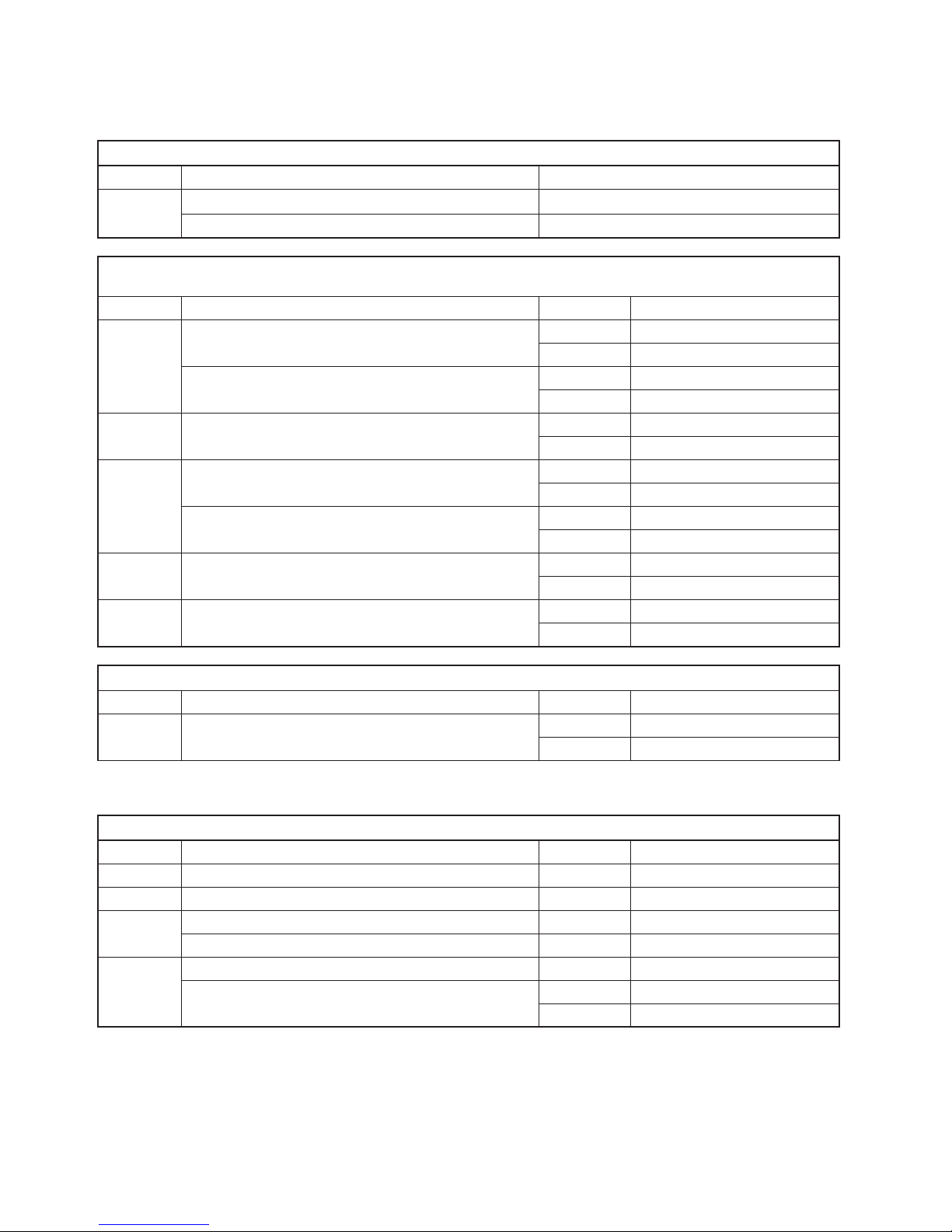
Display readout on the 4501 of sensor error detection and input
signal outside range
Sensor error detection limits
Sensor error detection (SE.BR, SE.SH):
Input Range Readout Limit
CURR Loop break (4..20 mA) SE.BR <=3.6mA;>=21mA
POTM All, SE.BR on all 3-wire SE.BR
> ca. 126 k
Ω
LIN.R
0...800
Ω
SE.BR
> ca. 875
Ω
0...10 kΩ SE.BR
> ca. 11 k
Ω
TEMP
TC SE.BR
> ca. 750 k
Ω / (1.25 V)
RTD, 2-, 3-, and 4-wire
No SE.SH for Pt10, Pt20 and Pt50
SE.BR
> ca. 15 k
Ω
SE.SH
< ca. 15
Ω
Outside range readout (IN.LO, IN.HI):
If the valid range of the A/D converter or the polynomial is exceeded
Input Range Readout Limit
VOLT
0...1 V / 0.2...1 V
IN.LO < -25 mV
IN.HI > 1.2 V
0...10 V / 2...10 V
IN.LO < -25 mV
IN.HI > 12 V
CURR 0...20 mA / 4...20 mA
IN.LO < -1.05 mA
IN.HI > 25.05 mA
LIN.R
0...800
Ω
IN.LO < -10 Ω
IN.HI > ca. 1075 Ω
0...10 kΩ
IN.LO < -10 Ω
IN.HI > 110 kΩ
POTM 0...100%
IN.LO < -0.5 %
IN.HI > 100.5 %
TEMP TC / Pt100
IN.LO < temperature range -2°C
IN.HI > temperature range +2°C
Display readout below min.- / above max. (-1999, 9999):
Input Range Readout Limit
All All
-1999 Display readout <-1999
9999 Display readout >9999
Sensor error check:
Device: Configuration Sensor error detection:
3114
OUT.ERR=NONE. OFF
Else: ON
Page 22

20 3114V101-UK
Error indications
Readout at hardware error
Error search Readout Error cause
CJC sensor error - check device temperature CJ.ER
Defect CJC sensor or CJC
temperature out
allowed range **
Flash memory error - default configuration is loaded FL.ER
Error in FLASH
(configuration)*
No communication NO.CO No communication
Input error - check input connection and reset power IN.ER
Error levels on
measurement inputs*
Programming mode only - no output signal PROG.
Offline configuration mode
(3114 powered by
communications
interface)***
Invalid configuration type or version TY.ER
Configuration read from
EEprom has invalid type
or rev. no.
Hardware error RA.ER RAM memory error*
Hardware error EE.ER EEPROM memory error*
Hardware error NO.CA
Device not
factory-calibrated
Hardware error AD.ER A/D converter error*
Hardware error EF.ER External Flash error*
Hardware error IF.ER Internal Flash error*
! All error indications in the display flash once per second (1 Hz), and the corresponding help text
is shown. If the error is a sensor error, the display backlight flashes as well - this is acknowledged
(stopped) by pushing the OK button.
* Error is acknowledged by entering the menu and saving or by resetting the device power
** Error can be disregarded by selecting input type different than TC.
*** Error indication does not flash. Error is acknowledged by connecting device power.
Page 23
A
B
C
D
E
F
G
H
I
J
K
+
-
A
Tx
D BF E C
H
mA
G
I
J
5
6
7
81
2
3
4
81 82 83 84 85
K
+
-
+
-
+
-
+
-
+
-
V
3114V101-UK 21
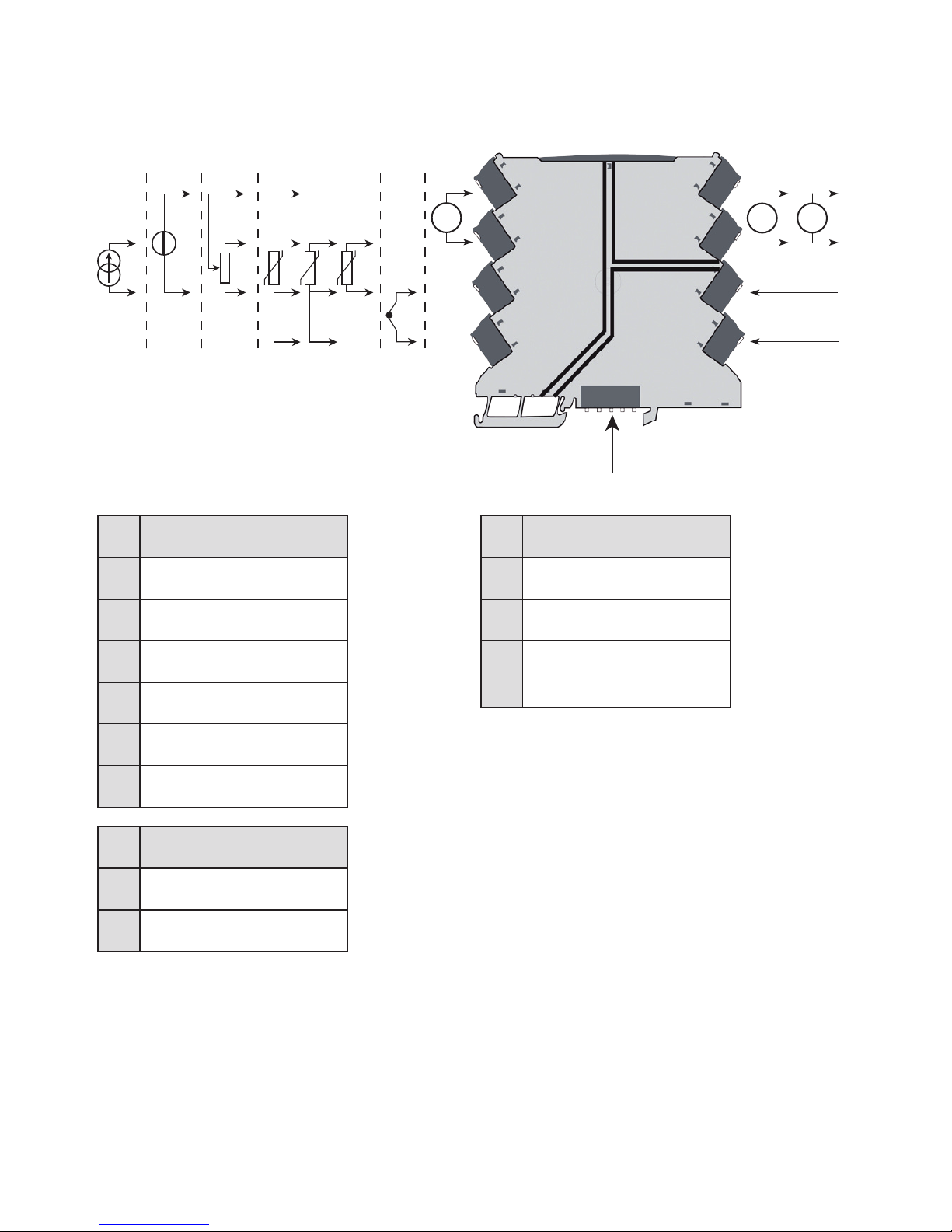
CONNECTIONS
Input signals
Current 1
TC
RTD
Potentiometer
Voltage
Current 2
Output signals
Current
Voltage
Supply
Supply +
Supply -
Power rail
connections
Input Output
Supply
Page 24
22 3114V101-UK
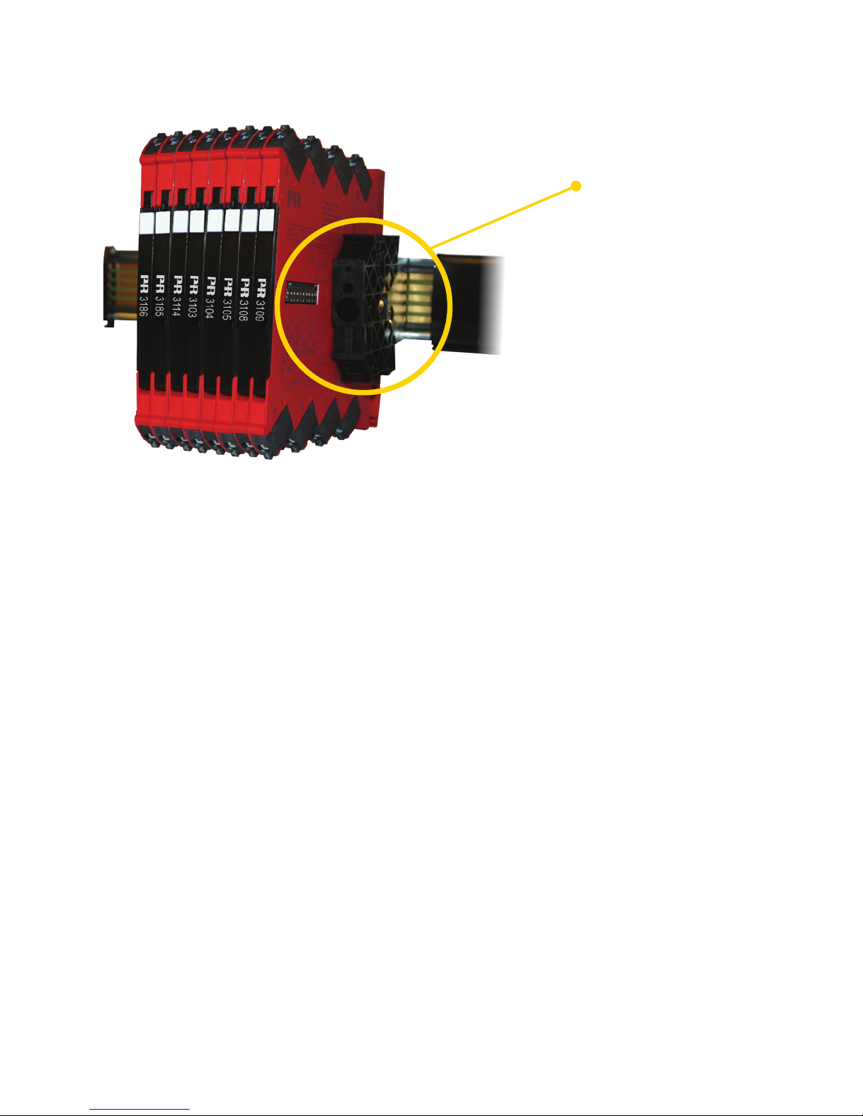
INSTALLATION ON POWER RAIL
The 3114 can be installed on a power rail (PR part number 9400) supported, if
necessary, by module stop for power rail (PR part number 9404). Power supply
units can be mounted on the power rail according to customer requirements.
Module stop
Page 25
3114V101-UK 23
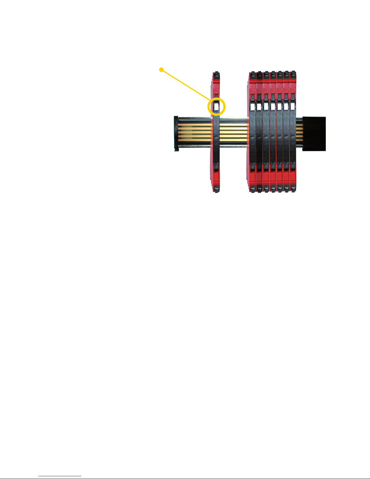
MARKING
The front cover of the 3114
series has been designed
with an area for affixation
of a click-on marker. The
area assigned to the marker
measures 5 x 7.5 mm.
Markers from Weidmüller’s
MultiCard System, type MF
5/7.5, are suitable.
Page 26

24 3114V101-UK
LED Condition
Output and
loop supply
Action required
OFF
No supply /
device error or
code-flash CRC error
De-energized
Connect supply /
replace device
1 Flash
(0.5 s OFF +
0.5 s ON)
Power-up or restart De-energized -
Flashing 13 Hz
(15 ms ON)
Device OK Energized -
Flashing 1 Hz
(15 ms ON)
Sensor error De-energized
Correct setting and
re-power device
Flashing 1 Hz
(0.5 s ON)
Restarting due to:
Supply error/hardware.
RAM or program flow error
De-energized
Adjust supply /
replace device
LED INDICATION
The device is equipped with a green power LED
in the front to indicate the operation status, see
the table below.
Page 27

3114V101-UK 25
DEFAULT CONFIGURATION
Input
Input type .................................................... Temperature
Voltage input ............................................... 0...10 V
Current input ............................................... 4...20 mA
Sensor connection (RTD+resistance) .......... 3 wire
R input range ............................................... 0...1000
Temperature unit ......................................... °C
Temperature type ........................................ Pt
Pt type ......................................................... Pt100
Ni type ......................................................... Ni100
TC type ........................................................ K
Display unit .................................................. °C
Decimal point .............................................. 000.0
Display low .................................................. 0.0
Display high ................................................. 100.0
Output
Output type ................................................. Current
Voltage output ............................................. 0...10 V
Current output ............................................. 4...20 mA
Analogue out on error ................................. 23 mA
Analogue out low ........................................ 0
Analogue out high ....................................... 150
Output limit .................................................. No
Advanced
LCD contrast ............................................... 3
LCD backlight .............................................. 4
TAG .............................................................. TAG NO.
Line 3 function ............................................. Analogue out
Use calibration ............................................ No
Enable password protection ....................... No
Calibration range ......................................... 0.0 / 100.0
Calibration point .......................................... 0.0 / 100.0
Language ..................................................... UK
Page 28

26 3114V101-UK
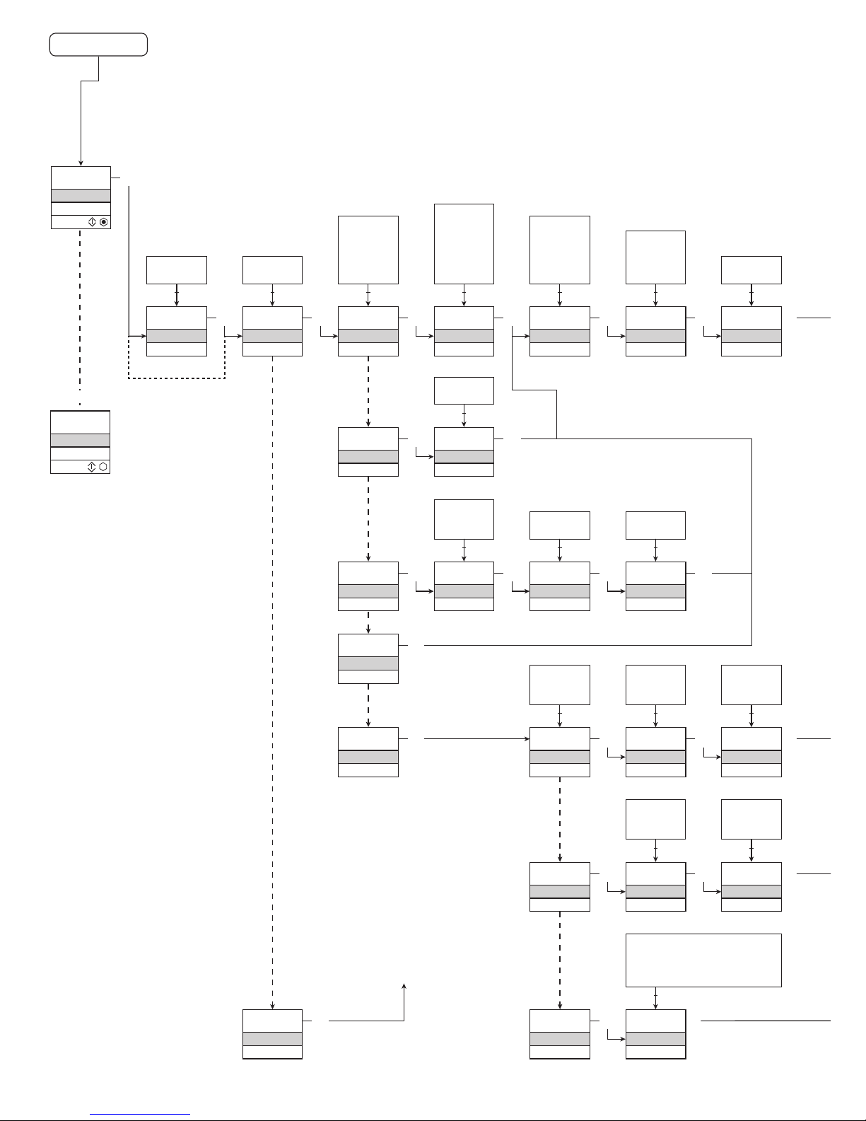
CONFIGURATION /
OPERATING THE FUNCTION KEYS
Documentation for routing diagram.
In general
When configuring the 3114, you will be guided through all parameters and you
can choose the settings which fit the application. For each menu there is a
scrolling help text which is automatically shown in line 3 on the display.
Configuration is carried out by using the 3 function keys:
1 will increase the numerical value or choose the next parameter
2will decrease the numerical value or choose the previous parameter
3will accept the chosen value and proceed to the next menu
When configuration is completed, the dispaly will return to the default state 1.0.
Pressing and holding
3 will return to the previous menu or return to the default
state (1.0) without saving the changed values or parameters.
If no key is activated for 1 minute, the display will return to the default state (1.0)
without saving the changed values or parameters.
Further explanations
Password protection: Programming access can be blocked by assigning a
password. The password is saved in the transmitter in order to ensure a high
degree of protection against unauthorised modifications to the configuration.
Default password 2008 allows acces to all configuration menus.
Signal and sensor error info via display front 4501
Sensor error (see limits in the table) is displayed as SE.BR (sensor break) or
SE.SH (sensor short). Signals outside the selected range (not sensor error,
see table for limits) are displayed as IN.LO indicating low input signal or IN.HI
indicating high input signal. The error indication is displayed in line 3 as text
and at the same time the backlight flashes. Line 4 of the display is a status line
which displays COM (flashing bullet) indicating correct functioning of 4501, and
arrow up/down which indicates tendency readout of the input signal.
Page 29

3114V101-UK 27
Signal and sensor error indication without display front
Status of the unit can also be read from the green LED in the front of the device.
Green flashing LED 13 Hz indicates normal operation.
Green flashing LED 1 Hz indicates sensor error.
No light in the LED indicates internal error.
Advanced functions
The unit gives access to a number of advanced functions which can be reached
by answering “Yes” to the point “adv.set”.
Display setup: Here you can adjust the brightness contrast and the backlight.
Setup of TAG number with 6 alphanumerics. Selection of functional readout
in line 3 of the display - choose between readout of analogue output or TAG
number.
Two-point process calibration: The unit can be process-calibrated in 2 points
to fit a given input signal. A low input signal (not necessarily 0%) is applied
and the actual value is entered via 4501. Then a high signal (not necessarily
100%) is applied and the actual value is entered via 4501. If you accept to use
the calibration, the unit will work according to this new adjustment. If you later
reject this menu point or choose another type of input signal the unit will return
to factory calibration.
Process simulation function: If you say ”yes” to the point “EN.SIM” it is possible
to simulate an input signal by means of the arrow keys and thus control the
output signal up or down. When you finalise the point with 3, the unit returns
to normal mode.
Password: Here you can choose a password between 0000 and 9999 in order
to protect the unit against unauthorised modifications to the configuration. The
unit is delivered default without password. If you have locked the unit with a
password by mistake, you can always open the menu by using the master
password 2008.
Language: In the menu ”lang.setup” you can choose between 7 different lan-
guage versions of help texts that will appear in the menu. You can choose
between UK, DE, FR, IT, ES, SE and DK.
Page 30

28 3114V101-UK
Selection of units
After choosing the input signal type you can choose the process units which will
be displayed in text line 2 (see table). By selection of temperature input the
process value is always displayed in Celsius or Fahrenheit. This is selected in
the menu point after selection of temperature input.
Memory
In the memory menu you can save the configuration of the device in the 4501,
and then move the 4501 onto another device of the same type and download
the configuration in the new device.
Page 31
0000
PASSW.
Txt 1
40.0
%
10.4
3
3
0000
9999
1 2
NO
ADV.SET
Txt 2
NO
YES
1 2
3
VOLT
IN TYPE
Txt 3
VOLT
CURR
LIN.R
POTM
TEMP
1 2
3
0-10
V.RANGE
Txt 4
2-10
0-10
1-5
0-5
0.2-1
0-1
1 2
3
CURR
IN TYPE
Txt 3
3
4-20
I.RANGE
Txt 5
0-20
4-20
1 2
3
LIN.R
IN TYPE
Txt 3
3
3W
CONNEC.
Txt 6
4W
3W
2W
1 2
3
POTM
IN TYPE
Txt 3
3
TEMP
IN TYPE
Txt 3
0
R 0%
Txt 7
0000
9999
1 2
3
2500
R 100%
Txt 8
0001
9999
1 2
3
Pt
SENSOR
Txt 10
Pt
NI
TC
1 2
3
YES
ADV.SET
Txt 2
3
Ni
SENSOR
Txt 10
3
TC
SENSOR
Txt 10
3
100
Pt TYPE
Txt 15
1000
-
10
1 2
3
3W
CONNEC.
Txt 6
4W
3W
2W
1 2
100
Ni TYPE
Txt 16
1000
-
50
1 2
3
3W
CONNEC.
Txt 6
4W
3W
2W
1 2
TC.B
TC.TYPE
Txt 17
TC.B TC.E TC.J TC.K
TC.L TC.N TC.R TC.S
TC.T TC.U TC.W3 TC.W5
TC.Lr
1 2
0.0
DISP.LO
Txt 13
999.9
-199.9
1 2
111.1
DEC.P
Txt 12
1111
111.1
11.11
1.111
1 2
3
UNIT
%
Txt 11
@C
mA
rpm
(69 units)
1 2
3
1.2
1.0
3
3
PROG
0.00mA
1.1
3114V101-UK 29
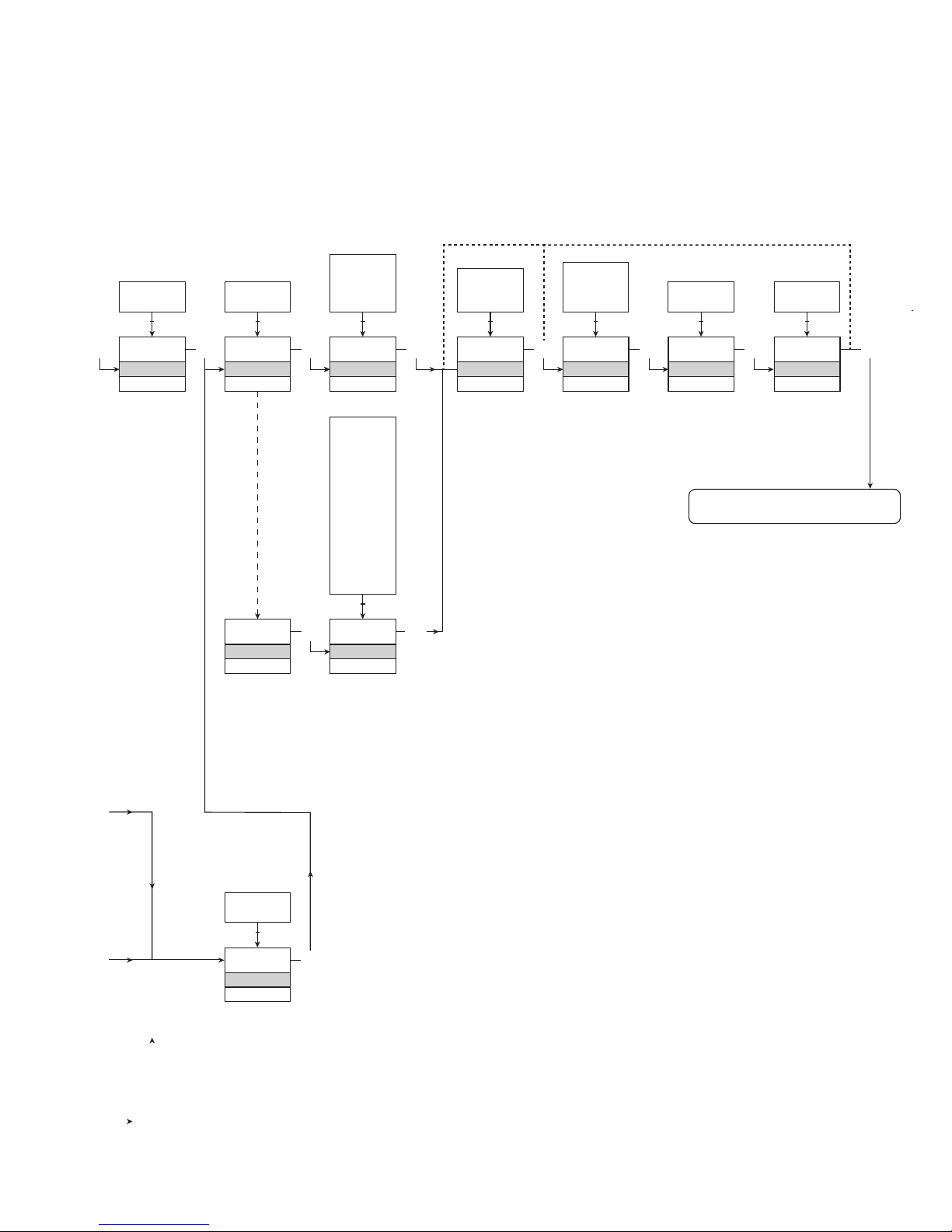
1.0=Defaultstate
Line 1 shows input
signal.
Line 2 shows UNIT.
By pressing 1 and 2
simultaneously line 3
alternates between
A.Out and TAG.
Line 4 shows com-
munication status.
1.1=The4501willpower
off if no key is acti-
vated for 1 minute.
1.2=Onlyifpasswordis
enabled.
1.3=Downscaleto0mA/
3.5 mA or 0 V.
Upscale to 23 mA or
110% of Vout high.
Only if input type
supports sensor error
check.
Not valid for these
input signals:
0...20 mA and voltage.
1.4=Onlyifinputsignalis
temperaure.
Continued on the page
Routing diagram ADV.SET
Hold 1 and 2:
Toggle Line 3 function
between A.Out / TAG.
(Setting is volatile - use DISP
setup menu to change and
store Line 3 function.)
Power up
Page 32
3
100.0
DISP.HI
Txt 14
999.9
-199.9
1 2
3 3
CURR
ANA.OUT
Txt 18
VOLT
CURR
1 2
3
4-20
O.RANGE
Txt 19
3
Volt
ANA.OUT
Txt 18
3
0-10
O.RANGE
Txt 23
10-2
10-0
5-1
5-0
1-0.2
1-0
2-10
0-10
1-5
0-5
0.2-1
0-1
1 2
NO
OUT.LIM
Txt 41
3
UP
OUT.ERR
Txt 22
UP
DOWN
NONE
1 2
3
0.0
OUT.LO
Txt 24
849
-200
1 2
1.3 1.4
3
3
@C
UNIT
Txt 9
@C
@F
1 2
3
@C
@F
%
A
bar
cm
ft
ft/h
ft/min
ft/s
g
gal/h
gal/min
GW
hp
hPa
Hz
in
in/h
in/min
in/s
ips
K
kA
kg
kJ
kPa
kV
kW
kWh
l
l/h
l/min
l/s
m
m/h
m/min
m/s
m/s2
m3
m3/h
m3/min
mA
mbar
mils
min
mm
mm/s
mol
MPa
mV
MW
MWh
N
Ohm
Pa
pH
rpm
s
S
t
t/h
uA
um
uS
V
W
Wh
yd
[blank]
20-4
20-0
4-20
0-20
1 2
3
3
YES
NO
1 2
150.0
OUT.HI
Txt 25
850
-199
1 2
1.4
3
3
30 3114V101-UK
ROUTING DIAGRAM
If no key is activated for 1 minute, the display will return to the default state 1.0
without saving configuration changes.
1 Increase value / choose next parameter
2 Decrease value / choose previous parameter
3 Accept the chosen value and proceed to the next menu
Hold 3 Back to previous menu / return to menu 1.0 without saving
To default state 1.0
Selectable UNITS:
Page 33
SAVE
MEMORY
Txt 27
3
SAVE
LOAD
1 2
MEM
SETUP
Txt 26
MEM
DISP
CAL
SIM
PASS
LANG
1 2
3
DISP
SETUP
Txt 26
3
3
CONTRA
Txt 28
3
9
0
1 2
9
LIGHT
Txt 29
3
9
0
1 2
TAGNO_
Txt 30
3
9
A
1 2
A.OUT
LINE 3
Txt 31
3
TAG
A.OUT
1 2
CAL
SETUP
Txt 26
3
YES
CAL.LO
Txt 32
YES
NO
1 2
3
NO
YES
CAL.HI
Txt 33
3
YES
NO
1 2
97.8
@C
Txt 40
3
850.0
-200
1 2
NO
YES
USE.CAL
Txt 38
3
YES
NO
1 2
SIM
SETUP
Txt 26
3
23.0
@C
Txt 34
850.0
-200
1 2
3
PASS
SETUP
Txt 26
3 3
YES
EN.PASS
Txt 35
3
YES
NO
1 2
3
LANG
SETUP
Txt 26
3
UK
LANGUA
Txt 37
3
DE, DK,
ES, FR,
IT, SE,
UK
1 2
NO
3
2.0
@C
Txt 39
850.0
-200
1 2
0000
NEW.PAS
Txt 36
9999
0000
1 2
3114V101-UK 31
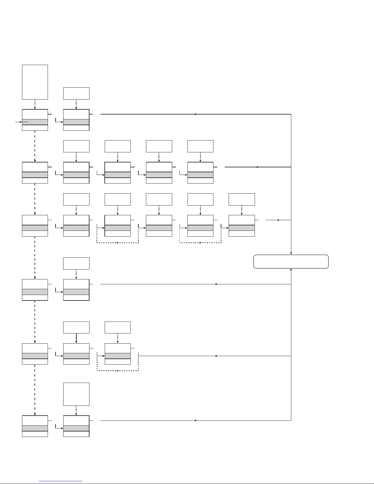
ROUTING DIAGRAM
ADVANCED SETTINGS (ADV.SET)
To default state 1.0
2.0 In the submenu simulation (SIM) you must
press 3 to return to the default state 1.0.
Page 34

32 3114V101-UK
[01]
[02]
[03]
[04]
[05]
[06]
[07]
[08]
[09]
[10]
[11]
[12]
[13]
[14]
[15]
[16]
[17]
[18]
[19]
[22]
[23]
[24]
[25]
[26]
[27]
[28]
[29]
[30]
[31]
[32]
[33]
[34]
[35]
[36]
[37]
[38]
[39]
[40]
[41]
[42]
Set correct password
Enter advanced setup menu?
Select temperature input
Select potentiometer input
Select linear resistance input
Select current input
Select voltage input
Select 0.0-1 V input range
Select 0.2-1 V input range
Select 0-5 V input range
Select 1-5 V input range
Select 0-10 V input range
Select 2-10 V input range
Select 0-20 mA input range
Select 4-20 mA input range
Select 2-wire sensor connection
Select 3-wire sensor connection
Select 4-wire sensor connection
Set resistance value low
Set resistance value high
Select Celsius as temperature unit
Select Fahrenheit as temperature unit
Select TC sensor type
Select Ni sensor type
Select Pt sensor type
Select display unit
Select decimal point position
Set display range low
Set display range high
Select Pt10 as sensor type
Select Pt20 as sensor type
Select Pt50 as sensor type
Select Pt100 as sensor type
Select Pt200 as sensor type
Select Pt250 as sensor type
Select Pt300 as sensor type
Select Pt400 as sensor type
Select Pt500 as sensor type
Select Pt1000 as sensor type
Select Ni50 as sensor type
Select Ni100 as sensor type
Select Ni120 as sensor type
Select Ni1000 as sensor type
Select TC-B as sensor type
Select TC-E as sensor type
Select TC-J as sensor type
Select TC-K as sensor type
Select TC-L as sensor type
Select TC-N as sensor type
Select TC-R as sensor type
Select TC-S as sensor type
Select TC-T as sensor type
Select TC-U as sensor type
Select TC-W3 as sensor type
Select TC-W5 as sensor type
Select TC-Lr as sensor type
Select current as analogue output type
Select voltage as analogue output type
Select 0-20 mA output range
Select 4-20 mA output range
Select 20-0 mA output range
Select 20-4 mA output range
SCROLLING HELP TEXT IN DISPLAY LINE 3
Select no error action - output undefined at error
Select downscale at error
Select upscale at error
Select 0.0-1 V output range
Select 0.2-1 V output range
Select 0-5 V output range
Select 1-5 V output range
Select 0-10 V output range
Select 2-10 V output range
Select 1-0.0 V output range
Select 1-0.2 V output range
Select 5-0 V output range
Select 5-1 V output range
Select 10-0 V output range
Select 10-2 V output range
Set temperature for analogue output low
Set temperature for analogue output high
Enter language setup
Enter password setup
Enter simulation mode
Perform process calibration
Enter display setup
Perform memory operations
Load saved configuration into device
Save configuration in display front
Adjust LCD contrast
Adjust LCD backlight
Write a 6-character device TAG
Analogue output value is shown in display line 3
Device TAG is shown in display line 3
Calibrate input low to process value?
Calibrate input high to process value?
Set the input simulation value
Enable password protection?
Set new password
Select language
Use process calibration values?
Set value for low calibration point
Set value for high calibration point
Limit output values to output range)
Programming mode only - no output signal
Page 35
Programmable displays with a wide
selection of inputs and outputs for display of temperature,
volume and weight, etc. Feature linearisation, scaling,
and difference measurement functions for programming
via PReset software.
Displays
A wide selection of transmitters
for DIN form B mounting and
DIN rail modules with analogue and digital
bus communication ranging from applicationspecic to universal transmitters.
Temperature
Galvanic isolators for analogue and
digital signals as well as HART
®
signals. A wide product
range with both loop-powered and universal isolators
featuring linearisation, inversion, and scaling of output
signals.
Isolation
Interfaces for analogue and digital signals
as well as HART
®
signals between
sensors / I/P converters / frequency signals and control
systems in Ex zone 0, 1 & 2 and for some modules in
zone 20, 21 & 22.
Ex interfaces
PC or front programmable modules with
universal options for input, output and
supply. This range offers a number of advanced features
such as process calibration, linearisation and autodiagnosis.
Universal
Page 36
www.prelectronics.fr
[email protected]
www.prelectronics.de
[email protected]
www.prelectronics.es
[email protected]
www.prelectronics.it
[email protected]
www.prelectronics.se
[email protected]
www.prelectronics.com
[email protected]
www.prelectronics.com
[email protected]
Head ofce
Denmark www.prelectronics.com
PR electronics A/S [email protected]
Lerbakken 10 tel. +45 86 37 26 77
DK-8410 Rønde fax +45 86 37 30 85
 Loading...