

Page 1
PERFORMANCE
MADE
SMARTER
Zone 2
ZONE 2
ZONE 2 / DIV 2
CCOE
Product manual
3100
6 mm series of isolators
and converters
TEMPERATURE | I.S. INTERFACES | COMMUNICATION INTERFACES | MULTIFUNCTIONAL | ISOLATION | DISPLAY
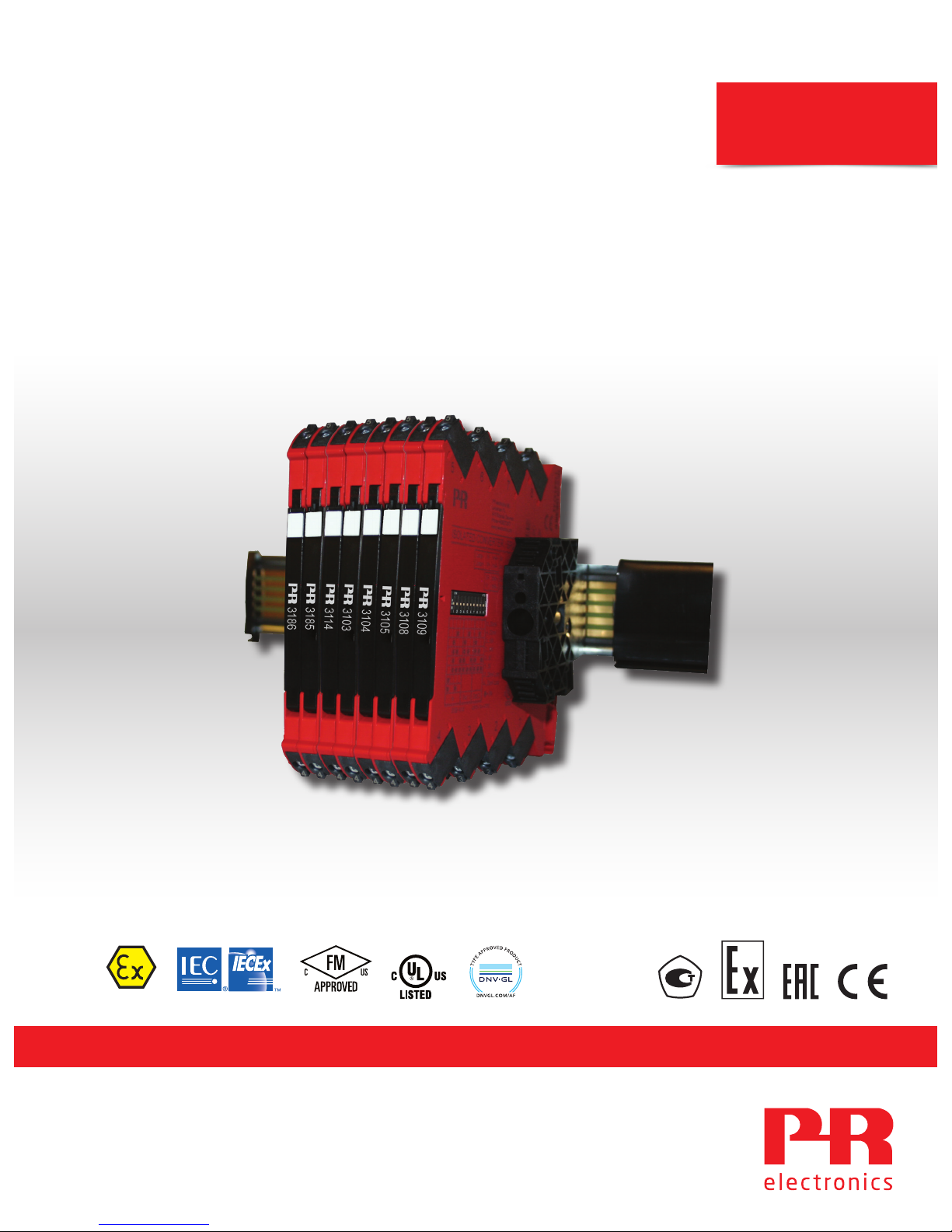
Models no. 3103 / 3104 / 3105 / 3108 / 3109
No. 3100V108-UK
Page 2

Communication
Display
I.S. Interface
Isolation
Multifunction
Temperature
6 Product Pillars
to meet your every need
With our innovative, patented technologies, we make signal conditioning smarter and simpler. Our portfolio is composed of six
product areas, where we offer a wide range of analog and digital devices covering over a thousand applications in industrial
and factory automation. All our products comply with or surpass the highest industry standards, ensuring reliability in even
the harshest of environments and have a 5-year warranty for greater peace of mind.
Individually outstanding, unrivalled in combination
Our range of temperature transmitters and sensors provides the highest level of signal integrity from the
measurement point to your control system. You can convert industrial process temperature signals to analog, bus or
digital communications using a highly reliable point-to-point solution with a fast response time, automatic selfcalibration, sensor error detection, low drift, and top EMC performance in any environment.
Our unique range of single devices covering multiple applications is easily deployable as your site standard. Having
one variant that applies to a broad range of applications can reduce your installation time and training, and greatly
simplify spare parts management at your facilities. Our devices are designed for long-term signal accuracy, low
power consumption, immunity to electrical noise and simple programming.
We provide inexpensive, easy-to-use, future-ready communication interfaces that can access your PR installed base
of products. The detachable 4501 Local Operator Interface (LOI) allows for local monitoring of process values,
device configuration, error detection and signal simulation. The next generation, our 4511 Remote Operator
Interface (ROI) does all that and more, adding remote digital communications via Modbus/RTU, while the analog
output signals are still available for redundancy.
With the 4511 you can further expand connectivity with a PR gateway, which connects via industrial Ethernet,
wirelessly through a Wi-Fi router or directly with the devices using our Portable Plant Supervisor (PPS) application.
The PPS app is available for iOS, Android and Windows.
Our display range is characterized by its flexibility and stability. The devices meet nearly every demand for display
readout of process signals, and have universal input and power supply capabilities. They provide a real-time
measurement of your process value no matter the industry, and are engineered to provide a user-friendly and
reliable relay of information, even in demanding environments.
We deliver the safest signals by validating our products against the toughest safety standards. Through our
commitment to innovation, we have made pioneering achievements in developing I.S. interfaces with SIL 2 Full
Assessment that are both efficient and cost-effective. Our comprehensive range of analog and digital intrinsically
safe isolation barriers offers multifunctional inputs and outputs, making PR an easy-to-implement site standard.
Our backplanes further simplify large installations and provide seamless integration to standard DCS systems.
Our compact, fast, high-quality 6 mm isolators are based on microprocessor technology to provide exceptional
performance and EMC-immunity for dedicated applications at a very low total cost of ownership. They can be
stacked both vertically and horizontally with no air gap separation between units required.
Page 3

3100V108-UK 3
6 mm series of
isolators and converters
3103 / 3104 / 3105 / 3108 / 3109
Table of contents
Warning ................................................................................................ 4
Symbol identification .................................................................................... 4
Safety instructions ...................................................................................... 4
UL installation ....................................................................................... 5
cFMus installation in Division 2 or Zone 2 .............................................................. 5
IECEx, ATEX installation in Zone 2 ..................................................................... 5
Flexible supply.......................................................................................... 7
Mounting and demounting of system 3000 ............................................................... 8
Installation on DIN rail / power rail ........................................................................ 9
Supply of power rail ..................................................................................... 9
Marking................................................................................................. 9
Side label ............................................................................................... 10
Applications ............................................................................................ 11
Product overview ....................................................................................... 12
Order................................................................................................... 13
Accessories ............................................................................................. 13
Accessories for power rail devices ........................................................................ 13
Technical data .......................................................................................... 13
Connections ............................................................................................ 16
LED indication........................................................................................... 17
DIP-switch programming................................................................................. 18
3104................................................................................................ 18
3105................................................................................................ 19
3109................................................................................................ 19
Document history ....................................................................................... 20
Page 4
4 3100V108-UK
Warning
To avoid the risk of electric shock and fire, the safety instructions of this guide must be observed and
the guidelines followed. The specifications must not be exceeded, and the device must only be applied
as described in the following. Prior to the commissioning of the device, this installation guide must be
examined carefully. Only qualified personnel (technicians) should install this device. If the equipment is
used in a manner not specified by the manufacturer, the protection provided by the equipment may be
impaired. Until the device is fixed, do not connect hazardous voltages to the device.
To avoid explosion and serious injury: Modules having mechanical failures must be returned to PR
electronics for repair or replacement.
Repair of the device must be done by PR electronics A/S only.
In applications where hazardous voltage is connected to in-/outputs of the device, sufficient spacing or
isolation from wires, terminals and enclosure - to surroundings (incl. neighboring devices), must be
ensured to maintain protection against electric shock.
Potential electrostatic charging hazard. To avoid the risk of explosion due to electrostatic charging of the
enclosure, do not handle the units unless the area is known to be safe, or appropriate safety measures
are taken to avoid electrostatic discharge.
Symbol identification
Triangle with an exclamation mark: Read the manual before installation and commissioning of the
device in order to avoid incidents that could lead to personal injury or mechanical damage.
The CE mark proves the compliance of the device with the essential requirements of the directives.
Ex devices have been approved acc. to the ATEX directive for use in connection with installations in
explosive areas.
Safety instructions
Receipt and unpacking
Unpack the device without damaging it and check whether the device type corresponds to the one ordered. The packing
should always follow the device until this has been permanently mounted.
Environment
Avoid direct sun light, dust, high temperatures, mechanical vibrations and shock, and rain and heavy moisture. If necessary,
heating in excess of the stated limits for ambient temperatures should be avoided by way of ventilation.
The device can be used for Measurement Category II and Pollution Degree 2.
The device is designed to be safe at least under an altitude up to 2 000 m.
Mounting
Only technicians who are familiar with the technical terms, warnings, and instructions in the manual and who are able to
follow these should connect the device.
GENERAL
CAUTION
HAZARDOUS
VOLTAGE
Page 5

3100V108-UK 5
Should there be any doubt as to the correct handling of the device, please contact your local distributor or, alternatively,
PR electronics A/S
www.prelectronics.com
Mounting and connection of the device should comply with national legislation for mounting of electric materials, i.e. wire
cross section, protective fuse, and location.
Descriptions of input / output and supply connections are shown in this installation guide and on the side label.
The device is provided with field wiring terminals and shall be supplied from a Power Supply having double / reinforced
insulation. A power switch should be easily accessible and close to the device. The power switch shall be marked as the
disconnecting unit for the device.
SYSTEM 3000 must be mounted on a DIN rail according to EN 60715.
UL installation
Use 60/75°C copper conducters only.
Wire size. . . . . . . . . . . . . . . . . . . . . . . . . . . . . . . . . . . . . . . . . AWG 26-12
UL file number . . . . . . . . . . . . . . . . . . . . . . . . . . . . . . . . . . . . . E314307
The device is an Open Type Listed Process Control Equipment. To prevent injury resulting from accessability to live parts the
equipment must be installed in an enclosure.
The power supply unit must comply with NEC Class 2, as described by the National Electrical Code® (ANSI / NFPA 70).
cFMus installation in Division 2 or Zone 2
FM17CA0003X / FM17US0004X . . . . . . . . . . . . . . . . . . . . . . . . . . Class I, Div. 2, Group A, B, C, D T4 or
Class I, Zone 2, AEx nA IIC T4 or Ex nA IIC T4
In class I, Division 2 or Zone 2 installations, the subject equipment shall be mounted within a tool-secured enclosure which is
capable of accepting one or more of Class I, Division 2 wiring methods specified in the National Electrical Code (ANSI/NFPA 70)
or in Canada in the Canadian Electrical Code (C22.1).
The 3000 System Isolators and Converters must be connected to limited output NEC Class 2 circuits, as outlined in the
National Electrical Code® (ANSI / NFPA 70), only. If the devices are connected to a redundant power supply (two separate
power supplies), both must meet this requirement.
Where installed in outdoor or potentially wet locations the enclosure shall at a minimum meet the requirements of IP54.
Warning: Substitution of components may impair suitability for zone 2 / division 2.
Warning: To prevent ignition of the explosive atmospheres, disconnect power before servicing and do not separate
connectors when energised and an explosive gas mixture is present.
Warning: Do not mount or remove devices from the power rail when an explosive gas mixture is present.
IECEx, ATEX installation in Zone 2
IECEx KEM 10.0068 X. . . . . . . . . . . . . . . . . . . . . . . . . . . . . . . . . Ex nA IIC T4 Gc
KEMA 10ATEX0147 X. . . . . . . . . . . . . . . . . . . . . . . . . . . . . . . . . II 3G Ex nA IIC T4 Gc
For safe installation the following must be observed. The device shall only be installed by qualified personnel who are familiar
with the national and international laws, directives and standards that apply to this area.
Year of manufacture can be taken from the first two digits in the serial number.
The devices shall be installed in a suitable enclosure providing a degree of protection of at least IP54 according to EN60529,
taking into account the environmental conditions under which the equipment will be used.
Page 6

6 3100V108-UK
When the temperature under rated conditions exceeds 70°C at the cable or conduit entry point, or 80°C at the branching point
of the conductors, the temperature specification of the selected cable shall be in compliance with the actual measured
temperature.
Provisions shall be made to prevent the rated voltage from being exceeded by transient disturbances of more than 40%.
For installation on power rail in Zone 2, only Power Rail type 9400 supplied by Power Control Unit type 9410 is allowed.
To prevent ignition of the explosive atmospheres, disconnect power before servicing and do not separate connectors when
energised and an explosive gas mixture is present.
Do not mount or remove devices from the power rail when an explosive gas mixture is present.
Cleaning
When disconnected, the device may be cleaned with a cloth moistened with distilled water.
Liability
To the extent the instructions in this manual are not strictly observed, the custom er cannot advance a demand against PR
electronics A/S that would otherwise exist according to the concluded sales agreement.
Page 7
3405
3100V108-UK 7
Flexible supply
The technical specifications specifies the maximum required power at nominal operating values, e.g. 24 V supply voltage,
60°C ambient temperature, 600 Ω load, and 20 mA output current.
External fuse characteristics:
The 2.5 A fuse must break after not more than 120 seconds at 6.4 A.
Protective fuse: 2.5 A.
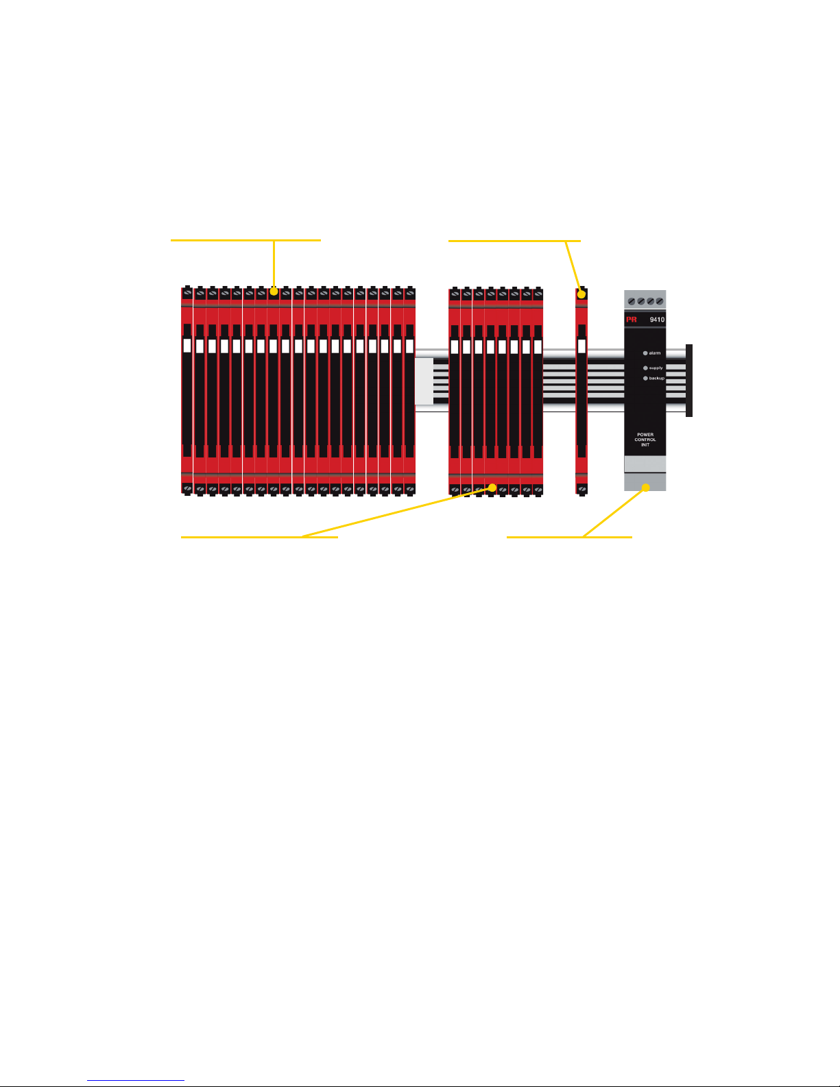
Power rail solution #1:
Alternately, you can connect 24 VDC to any
one 3000 device with power rail connector
which will then energize other units on the
rail.
Power rail solution #3:
The 9410 power control unit can energize
and power 96 W to the rail. Redundant power
supplies are possible.
Protective fuse: 2.5 A.
DIN rail solution - device daisy chain:
The units can be supplied with 24 VDC ±30%
via direct wiring and a loop between the
devices.
Power rail solution #2:
The 3405 power connector unit allows easy
connection of a 24 VDC / 2.5 A source to the
power rail.
Protective fuse: 0.4 A.
Protective fuse: Located inside the PR 9410.
Note:
Device type 3xxx-N can only be supplied via the DIN rail solution with direct wiring on each
device.
Page 8
8 3100V108-UK
Mounting and demounting of system 3000
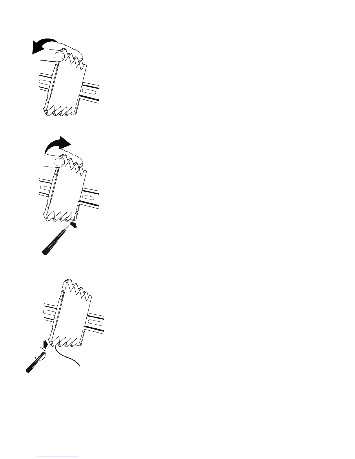
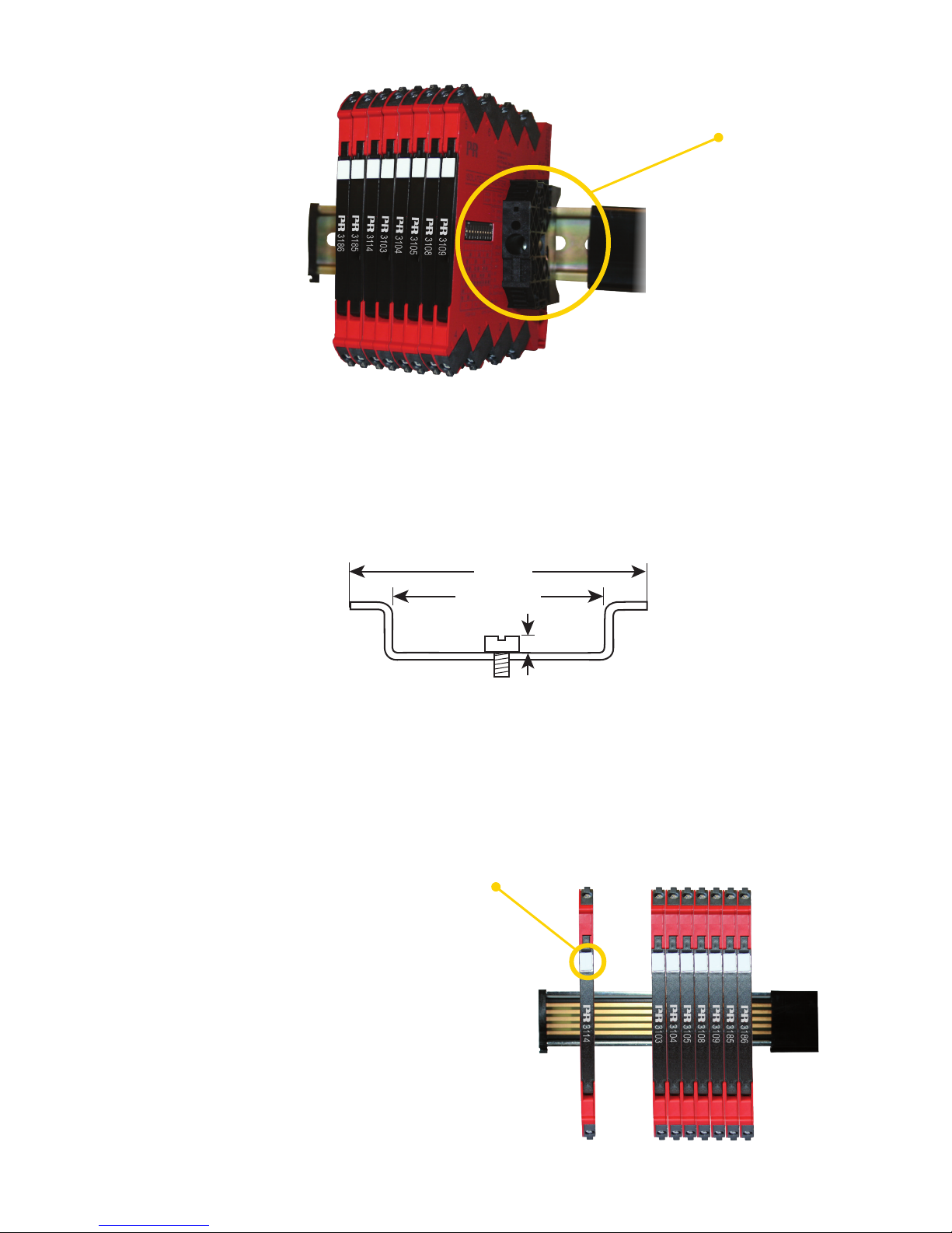
Picture 1:
Mounting on DIN rail / power rail.
Click the device onto the rail.
Picture 2:
Demounting from DIN rail / power rail.
First, remember to demount the connectors with hazardous voltages.
Detach the device from the DIN rail by lifting the bottom lock.
Picture 3:
Wire size AWG 26-12 / 0.13 x 2.5 mm
2
stranded wire.
Screw terminal torque 0.5 Nm.
Page 9
< 3.5 mm
> 24 mm
35 mm
3100V108-UK 9
Installation on DIN rail / power rail
The devices in the 3000 series can be installed on a DIN rail or on a power rail. For marine applications the devices must be
supported by a module stop (PR part number 9404). Power supply units can be mounted on the power rail according to
customer requirements.
If you want to install a 3000 device with power rail connectors on a standard DIN rail, the head of the screws holding the 7.5
mm DIN rail shall be no more than 3.5 mm high in order to avoid short circuit between the power rail connectors on the 3000
device and the screws.
Supply of power rail
It is possible to supply the power rail via the supply terminals.
The terminals can pass a current of max. 400 mA.
Marking
The front cover of the 3000 devices has been designed with
an area for affixation of a click-on marker. The area assigned
to the marker measures 5 x 7.5 mm. Markers from
Weidmüller’s MultiCard System, type MF 5/7.5, are suitable.
Module stop
Page 10
10 3100V108-UK
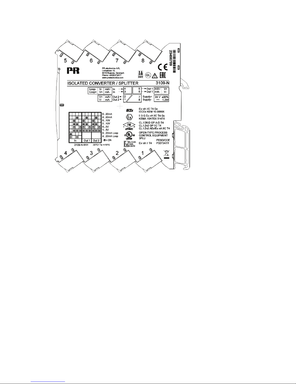
Side label
}
}
}
}
Approvals
Pin
connections
Type no.
Terminal numbers
Page 11

3100V108-UK 11
6 mm series of isolators and converters
3103 / 3104 / 3105 / 3108 / 3109
The product family 3103, 3104, 3105, 3108 & 3109 are slimline isolaters for 24 VDC
fixed supply and can be used for different purposes.
• Can be supplied separately or installed on power rail
• Can be delivered with customer parameterisation on request
• Approvals by CE, UL, DNV, GL, ATEX zone 2, IECEx zone 2 and FM Div. 2
• Possibility of loop supply output
Applications
The 3000 isolator family are designed for the automation and process industries. These devices are the result of extensive
development and test procedures making them very well suited for conversion and galvanic isolation in the following
applications:
• Isolation and 1:1 conversion of current signals in the range 0…20 mA.
• Isolation and conversion of standard DC signals.
• Power supply and signal isolator for 2-wire transmitters.
• Isolation and splitting of standard DC signals.
• Installation in ATEX Ex zone 2 / IECEx zone 2 / FM division 2.
• Suitable for environments with high vibration stress, e.g. ships
Page 12
12 3100V108-UK
Product overview
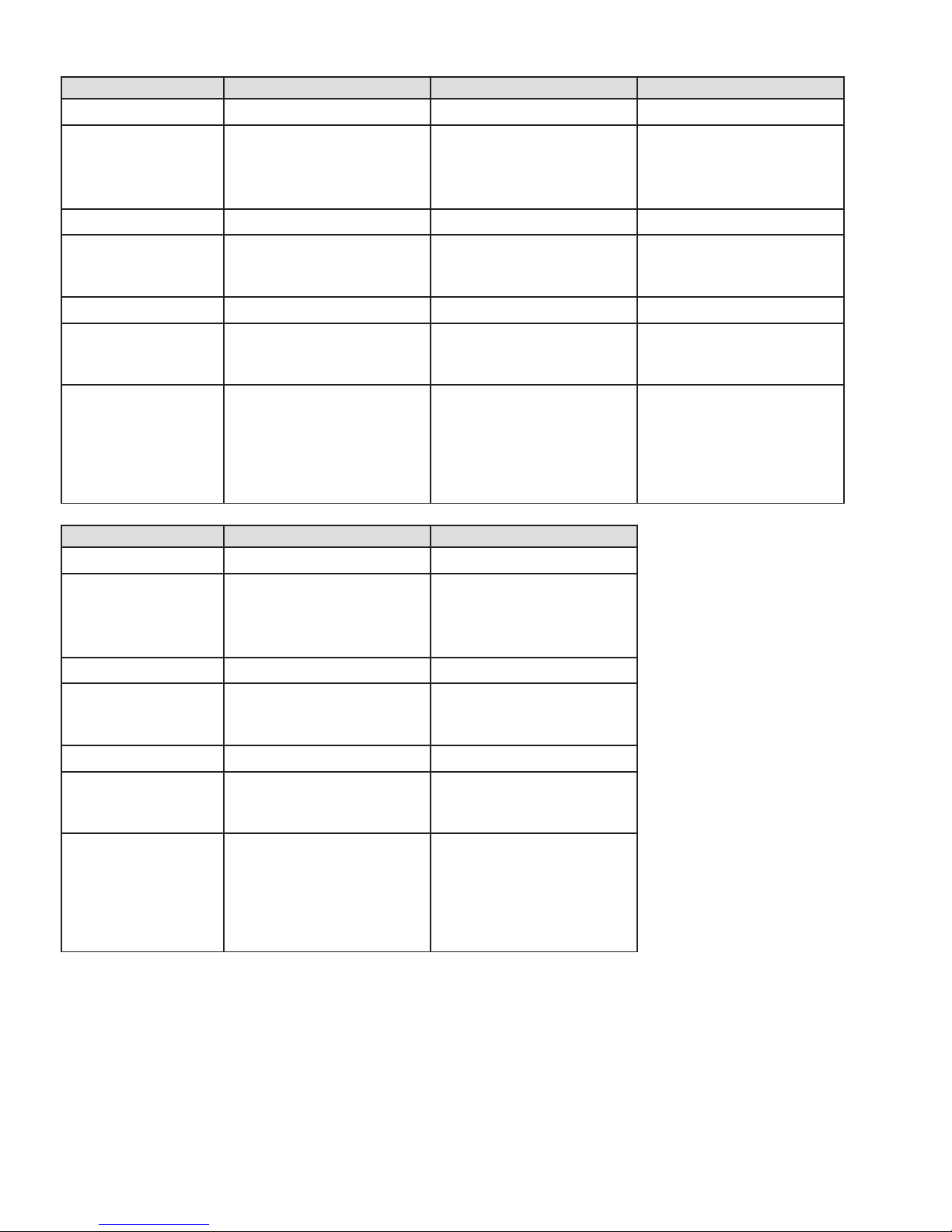
PR type no. 3103 3104 3105
PR product name Isolated repeater Isolated converter Isolated converter
Description Fixed loop isolator / repeater. Loop isolator / converter for
standard DC signals.
DIP-switch setup.
Loop isolator / converter for
standard DC signals.
DIP-switch setup.
Low cost.
Parameterisation None DIP-switch DIP-switch
Input signal 0…23 mA 0/2…10 V
0/1…5 V
0/4…23 mA
0/2…10 V
0/1…5 V
0/4…23 mA
Loop supply output >17 V @ 20 mA
Output signal (active) 0…23 mA (1:1) 0/2…10 V
0/1…5 V
0/4…23 mA
0/2…10 V
0/1…5 V
0/4…23 mA
Approvals UL, safety,
FM Div. 2,
ATEX zone 2,
IECEx zone 2,
DNV-GL, marine,
EAC Ex
UL, safety,
FM Div. 2,
ATEX zone 2,
IECEx zone 2,
DNV-GL, marine,
EAC Ex
UL, safety,
DNV, marine,
GL, marine,
EAC
PR type no. 3108 3109
PR product name Isolated repeater / splitter Isolated converter / splitter
Description Fixed loop isolator /
repeater with dual output.
Loop isolator / converter for
standard DC signals.
DIP-switch setup.
Dual output.
Parameterisation None DIP-switch
Input signal 0…23 mA 0/2…10 V
0/1…5 V
0/4…23 mA
Loop supply output >17 V @ 20 mA
Output signal (active) 0…23 mA (1:1) 0/2…10 V
0/1…5 V
0/4…23 mA
Approvals UL, safety,
FM Div. 2,
ATEX zone 2,
IECEx zone 2,
DNV-GL, marine,
EAC Ex
UL, safety,
FM Div. 2,
ATEX zone 2,
IECEx zone 2,
DNV-GL, marine,
EAC Ex
Page 13

3100V108-UK 13
Accessories
9404 = Module stop for rail
Accessories for power rail devices
3405 = Power rail connector unit
9400 = Power rail - 7.5 or 15 mm high
9410 = Power control unit
9421 = Power supply
Technical data
Environmental conditions:
Operating temperature . . . . . . . . . . . . . . . . . . . . . . . . . . . . . . . . -25°C to +70°C
Operating temperature, 3105 . . . . . . . . . . . . . . . . . . . . . . . . . . . . 0 to +70°C
Storage temperature . . . . . . . . . . . . . . . . . . . . . . . . . . . . . . . . . -40°C to +85°C
Calibration temperature. . . . . . . . . . . . . . . . . . . . . . . . . . . . . . . . 20...28°C
Relative humidity . . . . . . . . . . . . . . . . . . . . . . . . . . . . . . . . . . . < 95% RH (non-cond.)
Protection degree . . . . . . . . . . . . . . . . . . . . . . . . . . . . . . . . . . . IP20
Installation in pollution degree 2 & overvoltage category II.
Mechanical specifications:
Dimensions (HxWxD) . . . . . . . . . . . . . . . . . . . . . . . . . . . . . . . . . 113 x 6.1 x 115 mm
Weight approx. . . . . . . . . . . . . . . . . . . . . . . . . . . . . . . . . . . . . . 70 g
DIN rail type. . . . . . . . . . . . . . . . . . . . . . . . . . . . . . . . . . . . . . . DIN EN 60715 - 35 mm
Wire size. . . . . . . . . . . . . . . . . . . . . . . . . . . . . . . . . . . . . . . . . 0.13...2.5 mm
2
/ AWG 26...12 stranded wire
Screw terminal torque. . . . . . . . . . . . . . . . . . . . . . . . . . . . . . . . . 0.5 Nm
Vibration. . . . . . . . . . . . . . . . . . . . . . . . . . . . . . . . . . . . . . . . . IEC 60068-2-6
2...25 Hz. . . . . . . . . . . . . . . . . . . . . . . . . . . . . . . . . . . . . . . . ±1,6 mm
25...100 Hz . . . . . . . . . . . . . . . . . . . . . . . . . . . . . . . . . . . . . . ±4 g
Order
Type Version
3103 With power rail connector
Supplied via terminals
: -
: -N
3104 With power rail connector
Supplied via terminals
: -
: -N
3105 With power rail connector
Supplied via terminals
: -
: -N
3108 With power rail connector
Supplied via terminals
: -
: -N
3109 With power rail connector
Supplied via terminals
: -
: -N
Page 14

14 3100V108-UK
Common electrical specifications:
Supply voltage, DC. . . . . . . . . . . . . . . . . . . . . . . . . . . . . . . . . . . 16.8...31.2 VDC
Power requirements:
Max. required power is the maximum power needed at power supply terminals or rail connector.
Max. power dissipation is the maximum power dissipated at nominal operating values.
Isolation voltage, test. . . . . . . . . . . . . . . . . . . . . . . . . . . . . . . . . 2.5 kVAC
Isolation voltage working. . . . . . . . . . . . . . . . . . . . . . . . . . . . . . . 300 VAC (reinforced) /
250 VAC (Zone 2, Div. 2)
Double isolation . . . . . . . . . . . . . . . . . . . . . . . . . . . . . . . . . . . . Input / output 1 / output 2 / supply
Signal dynamics, input / output . . . . . . . . . . . . . . . . . . . . . . . . . . . Analog signal chain
Signal / noise ratio. . . . . . . . . . . . . . . . . . . . . . . . . . . . . . . . . . . Min. 60 dB
Cut-o frequency (3 dB) . . . . . . . . . . . . . . . . . . . . . . . . . . . . . . . > 100 Hz
Response time (0...90%, 100...10%):
mA / V input . . . . . . . . . . . . . . . . . . . . . . . . . . . . . . . . . . . . . < 7 ms
Accuracy. . . . . . . . . . . . . . . . . . . . . . . . . . . . . . . . . . . . . . . . . < ±0.05% of span
Accuracy, 3105. . . . . . . . . . . . . . . . . . . . . . . . . . . . . . . . . . . . . < ±0.2% of span
Temperature coecient. . . . . . . . . . . . . . . . . . . . . . . . . . . . . . . . < ±0.01% of span / ˚C
Temperature coecient, 3105 . . . . . . . . . . . . . . . . . . . . . . . . . . . < ±0.015% of span / ˚C
Auxiliary supplies:
2-wire supply (terminal 3 and 4) . . . . . . . . . . . . . . . . . . . . . . . . . . > 17 VDC / 20 mA
Current input:
Measurement range . . . . . . . . . . . . . . . . . . . . . . . . . . . . . . . . . . 0...23 mA
Programmable measurement ranges . . . . . . . . . . . . . . . . . . . . . . . . 0...20 and 4...20 mA
Input voltage drop . . . . . . . . . . . . . . . . . . . . . . . . . . . . . . . . . . . < 1.5 VDC
Input resistance . . . . . . . . . . . . . . . . . . . . . . . . . . . . . . . . . . . . Nom. 20 Ω + PTC 50 Ω
Voltage input:
Measurement range . . . . . . . . . . . . . . . . . . . . . . . . . . . . . . . . . . 0...10.25 VDC
Programmable measurement ranges . . . . . . . . . . . . . . . . . . . . . . . . 0...10 / 2...10 / 0...5 / 1...5 VDC
Input resistance . . . . . . . . . . . . . . . . . . . . . . . . . . . . . . . . . . . . ≥ 500 kΩ
Current output:
Signal range (span) . . . . . . . . . . . . . . . . . . . . . . . . . . . . . . . . . . 0...23 mA
Programmable signal ranges . . . . . . . . . . . . . . . . . . . . . . . . . . . . . 0...20 / 4...20 mA
Load, 3103, 3104 & 3105 . . . . . . . . . . . . . . . . . . . . . . . . . . . . . . ≤ 600 Ω
Load, 3108 & 3109 . . . . . . . . . . . . . . . . . . . . . . . . . . . . . . . . . . ≤ 300 Ω per channel
Load stability . . . . . . . . . . . . . . . . . . . . . . . . . . . . . . . . . . . . . . < 0.002% of span / 100 Ω
Current limit. . . . . . . . . . . . . . . . . . . . . . . . . . . . . . . . . . . . . . . ≤ 28 mA
Voltage output:
Signal range. . . . . . . . . . . . . . . . . . . . . . . . . . . . . . . . . . . . . . . 0...10 VDC
Programmable signal ranges . . . . . . . . . . . . . . . . . . . . . . . . . . . . . 0...10 / 2...10 / 0...5 / 1...5 VDC
Load (min.) . . . . . . . . . . . . . . . . . . . . . . . . . . . . . . . . . . . . . . . >10 kΩ
of span = of the selected range
EMC immunity influence . . . . . . . . . . . . . . . . . . . . . . . . . < ±0.5% of span
Extended EMC immunity:
NAMUR NE 21, A criterion, burst . . . . . . . . . . . . . . . . . . . . < ±1% of span
Typ e
Max. power
dissipation
Max. required
power
3103 0.60 W 0.65 W
3104 0.55 W 1.20 W
3105 0.52 W 0.80 W
3108 0.48 W 0.75 W
3109 0.60 W 1.20 W
Page 15

3100V108-UK 15
Observed authority requirements:
EMC. . . . . . . . . . . . . . . . . . . . . . . . . . . . . . . . . . . . . . . . . . . . 2014/30/EU
LVD . . . . . . . . . . . . . . . . . . . . . . . . . . . . . . . . . . . . . . . . . . . . 2014/35/EU
RoHS . . . . . . . . . . . . . . . . . . . . . . . . . . . . . . . . . . . . . . . . . . . 2011/65/EU
Approvals:
DNV-GL, Ships & Oshore . . . . . . . . . . . . . . . . . . . . . . . . . . . . . . VI-7-2
UL, Standard for Safety . . . . . . . . . . . . . . . . . . . . . . . . . . . . . . . . UL 61010-1
Safe Isolation . . . . . . . . . . . . . . . . . . . . . . . . . . . . . . . . . . . . . . EN 61140
EAC . . . . . . . . . . . . . . . . . . . . . . . . . . . . . . . . . . . . . . . . . . . . TR-CU 020/2011
I.S. / Ex approvals:
*ATEX 2014/34/EU . . . . . . . . . . . . . . . . . . . . . . . . . . . . . . . . . . KEMA 10ATEX0147 X
*IECEx . . . . . . . . . . . . . . . . . . . . . . . . . . . . . . . . . . . . . . . . . . KEM 10.0068 X
*c FM us . . . . . . . . . . . . . . . . . . . . . . . . . . . . . . . . . . . . . . . . . FM17US0004X / FM17CA0003X
*EAC Ex TR-CU 012/2011 . . . . . . . . . . . . . . . . . . . . . . . . . . . . . . RU C-DK.GB08.V.00410
*CCOE . . . . . . . . . . . . . . . . . . . . . . . . . . . . . . . . . . . . . . . . . . P337347/1
* Does not apply to 3105
Page 16
H
I
5
6
7
81
2
3
4
81 82 83 84 85
J
3103 3104 3105 3108 3109
A
x x x x x
B
x x
C
x x x
3103 3104 3105 3108 3109
D
x x x x x
E
x x x
F
x x
G
x
3103 3104 3105 3108 3109
H
x x x x x
I
x x x x x
J
x x x x x
+
-
+
-
mA V
+
-
A
+
-
Tx
C
F
ED
+
-
+
-
V
G
+
-
mA
B
16 3100V108-UK
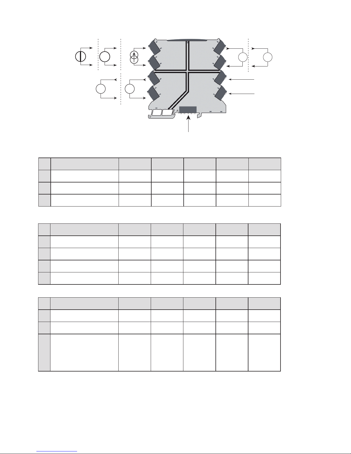
Input signals
Current 1
Voltage 1
Current 2
Voltage 2
Input signals
Current
Tx
Voltage
Supply
Supply +
Supply -
Power rail connections
(Only type 31xx with
power rail option)
Input
Output
ch. 1
SupplyOutput
ch. 2
Connections
Page 17
3100V108-UK 17
LED indication
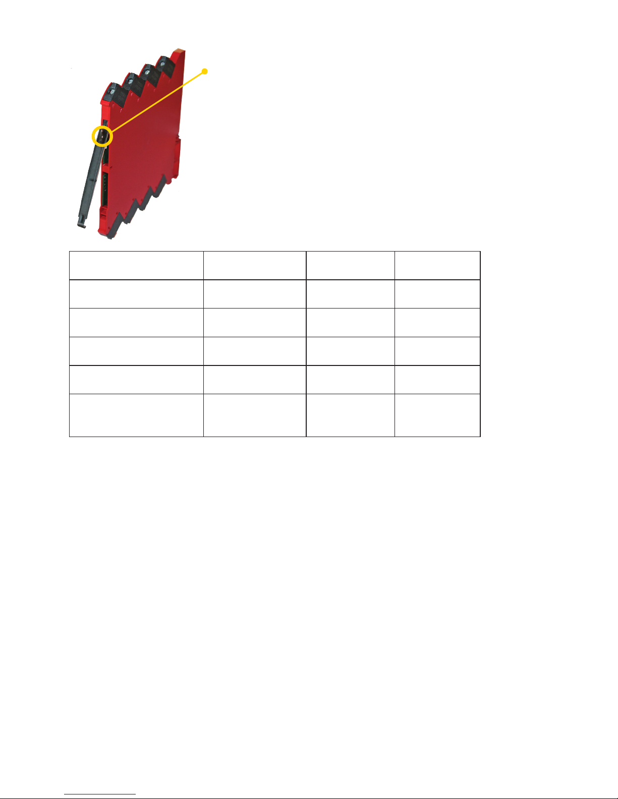
The device is equipped with a green power LED in the front to indicate the operation
status, see the table below.
Condition LED
Output and
loop supply
Action required
No supply / device error OFF De-energized
Connect supply /
replace device
Power-up or restart
1 Flash
(0.5 s OFF + 0.5 s ON)
De-energized -
Device OK
Flashing 13 Hz
(15 ms ON)
Energized -
Incorrect DIP-switch setting
Flashing 1 Hz
(15 ms ON)
De-energized
Correct setting and
re-power device
Restarting due to:
Supply error/hardware.
RAM or program flow error
Flashing 1 Hz
(0.5 s ON)
De-energized
Adjust supply /
replace device
Page 18
1 2 3 4 5 6 7 8 9 10
0…20 mA OFF OFF OFF OFF 0…20 mA OFF OFF OFF NA NA NA
4…20 mA OFF OFF ON OFF 4…20 mA OFF ON OFF NA NA NA
0…10 V OFF ON OFF OFF 0…10 V ON OFF OFF NA NA NA
2…10 V OFF ON ON OFF 2…10 V ON ON OFF NA NA NA
0…5 V OFF ON OFF ON 0…5 V ON OFF ON NA NA NA
1…5 V OFF ON ON ON 1…5 V ON ON ON NA NA NA
0...20 mA Tx ON OFF OFF OFF
4...20 mA Tx ON OFF ON OFF
18 3100V108-UK
DIP-switch programming
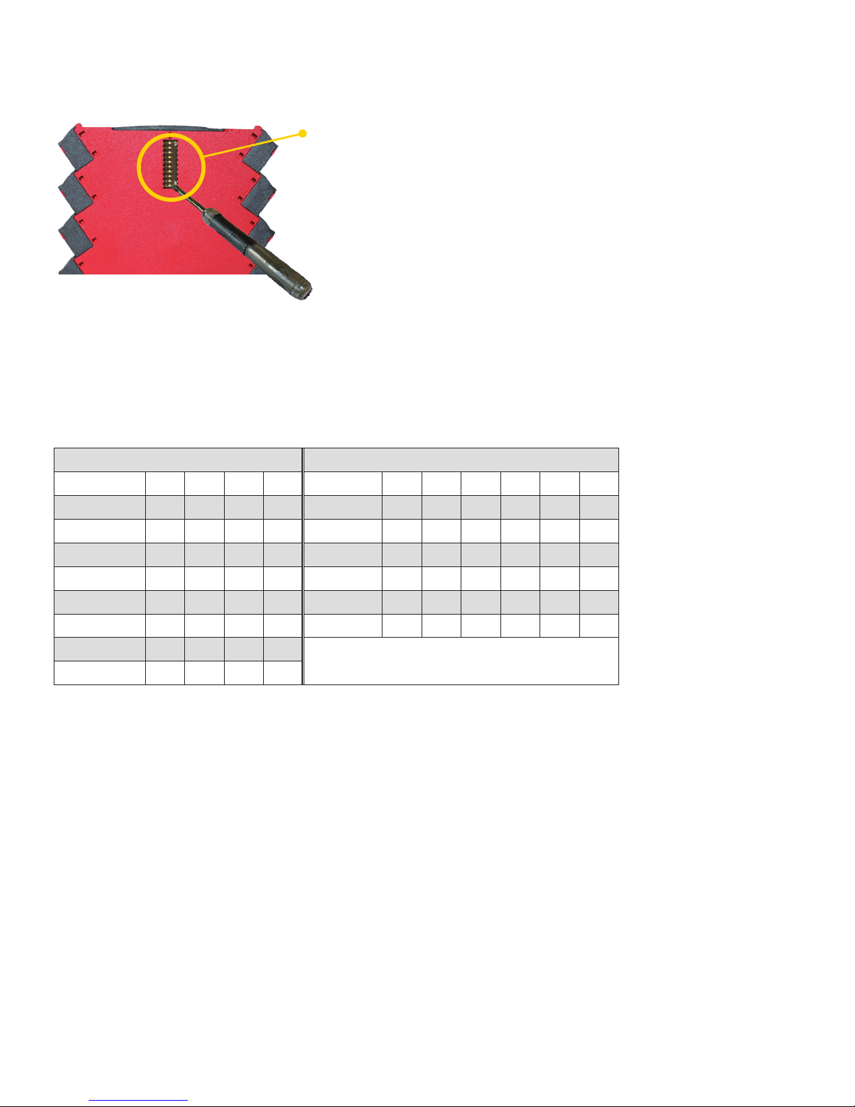
The devices 3104, 3105 and 3109 can be configured via DIP-switches. The DIP-switches are located on the side of the device
and can be adjusted with a small screwdriver or other implement.
Adjustment of DIP-switches.
Default factory settings are:
Input = 0…20 mA
Output = 0…20 mA
All DIP-switches in the OFF position
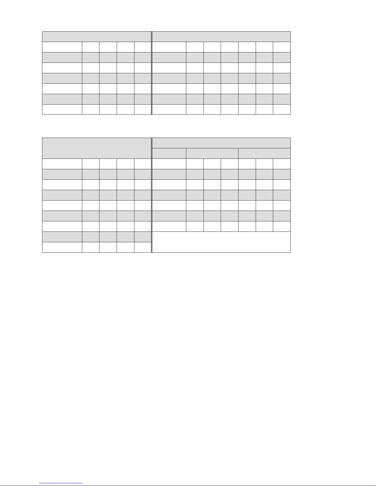
The tables below show the configuration based on DIP-switch settings.
NA = no function of DIP-switch.
3104
Input setup Output setup
Page 19
1 2 3 4 5 6 7 8 9 10
0…20 mA NA OFF OFF OFF 0…20 mA OFF OFF OFF NA NA NA
4…20 mA NA OFF ON OFF 4…20 mA OFF ON OFF NA NA NA
0…10 V NA ON OFF OFF 0…10 V ON OFF OFF NA NA NA
2…10 V NA ON ON OFF 2…10 V ON ON OFF NA NA NA
0…5 V NA ON OFF ON 0…5 V ON OFF ON NA NA NA
1…5 V NA ON ON ON 1…5 V ON ON ON NA NA NA
1 2 3 4 5 6 7 8 9 10
0…20 mA OFF OFF OFF OFF 0…20 mA OFF OFF OFF OFF OFF OFF
4…20 mA OFF OFF ON OFF 4…20 mA OFF ON OFF OFF ON OFF
0…10 V OFF ON OFF OFF 0…10 V ON OFF OFF ON OFF OFF
2…10 V OFF ON ON OFF 2…10 V ON ON OFF ON ON OFF
0…5 V OFF ON OFF ON 0…5 V ON OFF ON ON OFF ON
1…5 V OFF ON ON ON 1…5 V ON ON ON ON ON ON
0...20 mA Tx ON OFF OFF OFF
4...20 mA Tx ON OFF ON OFF
3100V108-UK 19
3105
Input setup Output setup
3109
Input setup Output setup
Channel 1 Channel 2
Page 20

Document history
The following list provides notes concerning revisions of this document.
Rev. ID Date Notes
108 1745 Models 31xx-N added
Specifications for max. required power and power
dissipation added
CCOE approval added
We are near you,
all over the world
All our devices are backed by expert service and a 5-year
warranty. With each product you purchase, you receive
personal technical support and guidance, day-to-day
delivery, repair without charge within the warranty period
and easily accessible documentation.
We are headquartered in Denmark, and have offices and
authorized partners the world over. We are a local
business with a global reach. This means that we are
always nearby and know your local markets well.
We are committed to your satisfaction and provide
PERFORMANCE MADE SMARTER all around the world.
For more information on our warranty program, or to
meet with a sales representative in your region, visit
prelectronics.com.
Our trusted red boxes are supported wherever you are
Page 21

PR electronics is the leading technology company specialized in making industrial process
control safer, more reliable and more efficient. Since 1974, we have been dedicated to
perfecting our core competence of innovating high precision technology with low power
consumption. This dedication continues to set new standards for products communicating,
monitoring and connecting our customers’ process measurement points to their process
control systems.
Our innovative, patented technologies are derived from our extensive R&D facilities and
from having a great understanding of our customers’ needs and processes. We are guided
by principles of simplicity, focus, courage and excellence, enabling some of the world’s
greatest companies to achieve PERFORMANCE MADE SMARTER.
Benefit today from
PERFORMANCE MADE SMARTER
www.prelectronics.com
 Loading...