

Page 1

C546 Elliptical Fitness Crosstrainerl
Page 1
C546 Elliptical Fitness Crosstrainer
Warning: This service manual is for use by Precor trained service providers only.
If you are not a Precor Trained Servicer, you must not attempt to service any Precor Product;
Call your dealer for service.
This document contains information required to perform the majority of troubleshooting, and
replacement procedures required to repair and maintain this product.
This document contains general product information, software diagnostic procedures (when
available), preventative maintenance procedures, inspection and adjustment procedures,
troubleshooting procedures, replacement procedures and electrical block and wiring diagrams.
To move directly to a procedure, click the appropriate procedure in the bookmark section to the
left of this page. You may “drag” the separator bar between this page and the bookmark section
to change the size of the page being viewed.
© 2003 Precor Incorporated
Unauthorized Reproduction and Distribution Prohibited By Law
Page 2

C546 Elliptical Fitness Crosstrainer
Page 2
Section One - Things You Should Know
C546 Serial Codes and Manufacturing Dates
The C546 has been manufactured in three versions. The applicable serial codes and
manufacturing dates associated with each version will be detailed below. When servicing a C546
it is critical that you are aware of which version of C546 you are servicing. The differences in the
versions may greatly impact service requirements and procedures. For convenience, the
versions detailed below will be referred to as version 1, version 2 or version 3 in the reminder of
this service manual. Any procedures that do not reference a specific version is applicable to all
versions of the C546.
Version 1 was manufactured between March 1998 and September 2000. The serial codes
associated with version 1 are 4H, 4K, 4L, 4J, 4M, 4N, 4P, 4R, 4S, 4T, 4U, 4Q, 4V, 4X, 4Y, 4W,
4Z, 5A, 5V, 5W, 5X and H9.
Version 2 was manufactured between July 2000 and August 2001. The serial codes associated
with version 2 are 69, 75, 8N, 9A, 9B, 9K, AP, AS, AT, AY, AX, AZ, BL, BM, BN, BP, BR, BT, BW,
BY, CA, CB, CC, CD and CE.
Version 3 was manufactured between August 2001 and the present. The serial codes
associated with version 3 are DC, DE, EX, GT and GU.
Right, Left, Front, and Back Conventions
In this manual, right, left, front, and back are from the perspective of a user standing on the EFX
546, facing the display enclosure.
Warning and Caution Statements and General Safety Guidelines
Warning statements indicate a particularly dangerous activity. Warning statements you will find in
this manual include:
• To remove power from the EFX, the power cord must be disconnected from the wall outlet.
Always ensure that the EFX is unplugged from the wall outlet when you inspect or ad just the
EFX, or when you isolate, remove, or replace an EFX component.
• Removing the covers exposes high voltage components and potentially dangerous
machinery. Exercise extreme caution when you perform maintenance procedures with the
hood removed.
• During service operations you will be very close to moving machinery and high voltage
components. When you perform maintenance procedures with the covers removed, remove
jewelry (especially from ears and neck), tie up long hair, remove neck ties, and do not wear
loose clothing.
• Exercise caution when touching any wire or electrical component during EFX operation.
Page 3

C546 Elliptical Fitness Crosstrainerl
Page 3
• A pinching hazard exists when the unit is operated by turning the crankarms by hand. It is
possible to seriously pinch a finger between the crankarm and stairarm. The stairarms
should be removed before operating the crankarms by hand.
Caution statements are intended to prevent damage to the EFX as a result of the current activity.
Caution statements included in this manual are listed below:
• Notice the orientation notch on the PROM. These components must be positioned with the
correct notch orientation.
• When it is necessary to lift or move the EFX, ensure that the EFX has adequate support and
that you use proper lifting techniques.
Safety guidelines you should know and follow include:
• Read the owner’s manual and follow all operating instructions.
• Operate the EFX on a solid, level surface.
Page 4

C546 Elliptical Fitness Crosstrainer
Page 4
• Visually check the EFX before beginning service or maintenance operations. If it is not
completely assembled or is damaged in any way, exercise extreme caution while operating
and checking the EFX.
• When operating the EFX, do not wear loose clothing. Do not wear shoes with heels or
leather soles. Check the soles of your shoes and remove any embedded stones. Tie long
hair back.
• Do not rock the unit. Do not stand or climb on the handlebars, display enclosure, or cover.
• Do not set anything on the handlebars, display enclosure, or cover. Never place liquids on
any part of the EFX, while performing service. A water bottle holder is furnished as standard
on the EFX 546.
• To prevent electrical shock, keep all electrical components, such as the power cord and
circuit breaker away from water and other liquids.
• Do not use accessory attachments that are not recommended by the manufacturer-such
attachments might cause injuries.
General Information
On units manufactured prior to August 16, 1998 a single lift connector (J4) was used. On
subsequent units the lift motor wiring is in the J3 connector and the lift potentiometer wiring is in
the J4 connector. This text will use the connections used on current production units. For units
manufactured prior to August 16, 1998, convert the lift connections as shown:
CONNECTION 8/16/98 AND LATER
CONNECTION PRIOR TO 8/16/98
J3 terminal 1 J4 terminal 1
J3 terminal 2 J4 terminal 2
J3 terminal 3 J4 terminal 3
J4 terminal 1 J4 terminal 4
J4 terminal 2 J4 terminal 5
J4 terminal 3 J4 terminal 6
For the latest exploded view, part number and part pricing information, visit the Precor dealer
website at “www.precor.com/Dealer.
Tools Required
Multimeter Allen wrench set
Anti-static kit Screwdriver set
4” - 6” gear puller Straight edge
“C” clamp or Carpenter’s clamp Precor part number 20030-117 belt gauge
US and metric end wrench set
US and metric socket wrench set
Torque wrench, 200 in/lbs.
Page 5

C546 Elliptical Fitness Crosstrainerl
Page 5
Section Two - Preventive Maintenance
Preventive maintenance measures are either scheduled or unscheduled. Scheduled preventive
maintenance activities are included here so that you are aware of preventive measures
performed on a regular basis.
Regular Preventive Maintenance (Owner)
Cleanliness of the EFX and its operating environment will keep maintenance problems and
service calls to a minimum. Precor recommends that you perform the following preventive
maintenance schedule.
After Each Use
• Turn off and unplug the EFX.
• Wipe down the covers, handlebars, stairarm wheels and stairarm ramps with a damp cloth.
Daily Maintenance
Clean the EFX’s frame, covers, stairarms, stairarm ramps and stairarm wheels using water or
“Simple Green”. Wipe the surface of the electronic console with a damp sponge or soft cloth. Dry
with a clean towel. “Simple Green” is the only cleaning solution that has been tested and
approved for use on the C546 ramps. Use of any other cleaner, may cause degradation of the
ramp anodizing and void the ramp warranty. The use of an acid (citric) based cleaner will cause
ramp anodizing damage and is not authorized by Precor.
Weekly Maintenance
• Vacuum underneath the EFX, following these steps:
1. Turn off the EFX with the circuit breaker, then unplug it from the wall outlet
2. Place the EFX on its side.
Note:
Place a drop cloth under the EFX to protect the flooring and to ensure that the EFX han drail
is not scratched or damaged.
3. Vacuum the rug or damp mop the floor.
4. Make sure that the floor is dry before returning the EFX to an upright position.
Page 6

C546 Elliptical Fitness Crosstrainer
Page 6
Quarterly Maintenance
1. Remove front and rear covers.
2. Clean and lubricate the lift motor drive screw with bearing grease.
3. Check the step up and input belt tension as in Procedure 5.3.
4. Replace both covers.
On-Site Preventive Maintenance (Service Technician)
When you are called to service a EFX, perform these preventive maintenance activities:
• Perform the software diagnostics. Check LED and keypad function. Record the odometer
reading.
• Check speed sensor function (is the stride rate displayed when the unit is in operation?). If
not, see Procedure 6.4
• Does the ramp (lift) operate smoothly and quietly? If not, see Procedure 6.5.
• Visually inspect the drive belts for cracks, fraying or excessive wear.
• Inspect the power cord. If the power cord is damaged, install a new power cord.
• Visually examine all wires and check connectors and wire connections. Secure connections
and replace wiring as necessary.
.
Page 7

C546 Elliptical Fitness Crosstrainerl
Page 7
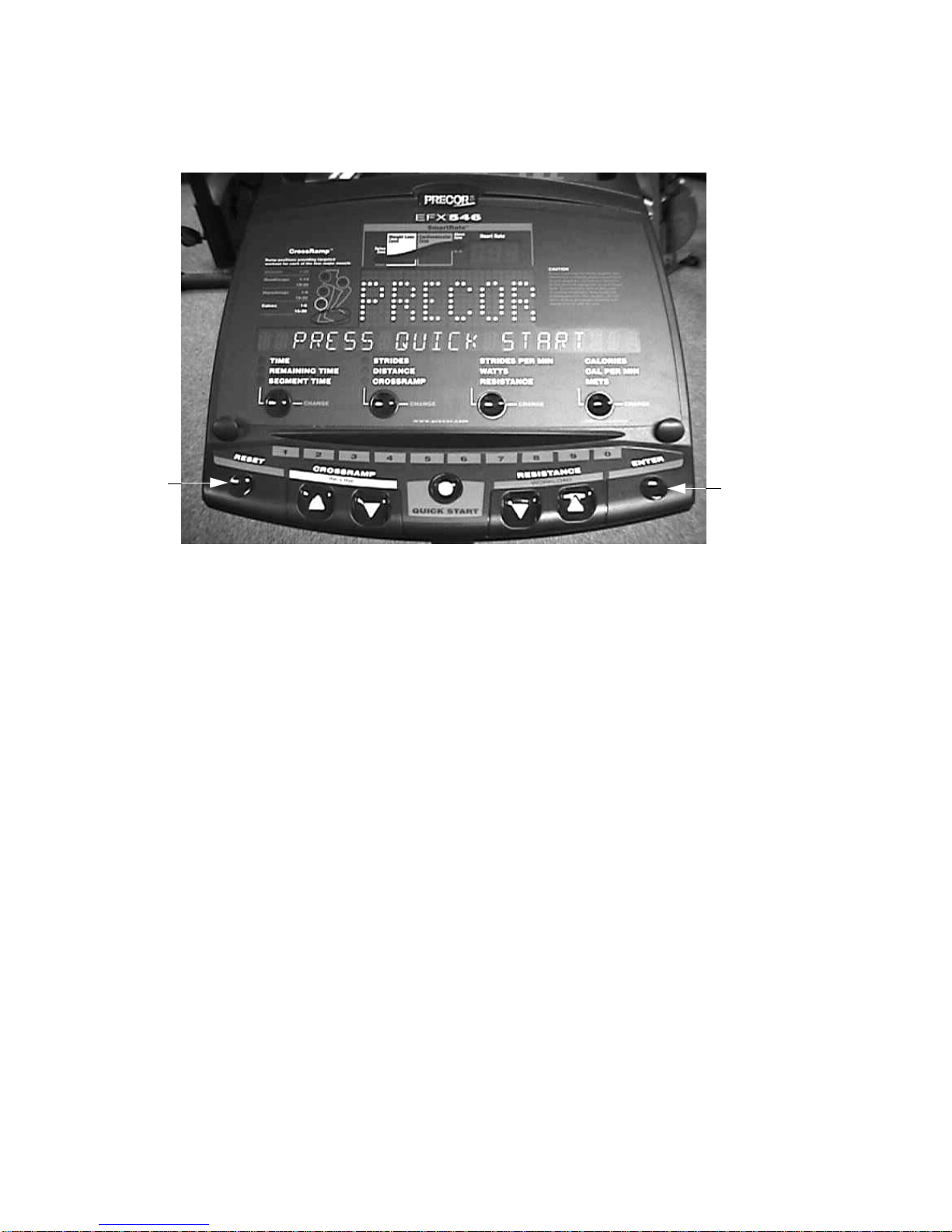
Procedure 3.1 - Software Access Codes
The C546 uses the standard access codes to provide access to the various software features. In
using the standardized access codes the keys are hypothetically numbered left to right with key
#1 on the far left and key #7 on the far right. The standard access codes use all sequential key
presses. The allowable delay between key presses is short. If too much time is taken between
key presses the access procedure will be aborted. If the access is aborted, it will be necessary to
start over from the beginning. See Diagram 3.1.
Standard Access Codes
Diagnostics Keys RESET,5,1,7,6,5,7,6,1
Odometer Keys RESET,6,5
Club Settings Keys RESET,5,6,5,1,5,6,5
Page 8

C546 Elliptical Fitness Crosstrainer
Page 8
Procedure 3.2 - Accessing the Diagnostic Program (version
1)
The EFX diagnostic software cycles through the following tests:
• LED Diagnostics
• Power Bits
• Lift Calibration Number
• Heart Rate
• Keypad Test
Procedure
1. Plug the power cord into the wall outlet, then turn on the EFX with the circuit breaker.
2. Press keys RESET,5,1,7,6,5,7,6,1., sequentially.
3. Watch the upper display as the LED test progresses. The test will illuminate every LED on
the display. The test will illuminate the LED’s in a specific pattern. When you are familiar
with the pattern, it is easy to determine when a LED does not illuminate.
4. If you do not observe the LED illumination sequences described in Step 3...
THEN... OTHERWISE...
Replace the upper PCA as described The LED test passed successfully;
in Procedure 7.2 or 7.3. continue with the next step.
5. Power Bits will be displayed. Power bits indicates the amount of power being applied to the
eddy current magnets and will vary directly with the resistance. Press ENTER to continue.
6. With LIFT displayed in the right display window, watch the right display window (shown in
Diagram 3.1). Press the CROSSRAMP
▲ or CROSSRAMP ▼ keys one at a time. Ve rify that
the lift calibration number increments or decrements as each of the CROSSRAMP keys are
pressed.
Page 9

C546 Elliptical Fitness Crosstrainerl
Page 9
Diagram 3.1 - C546 Display
7. Press ENTER, then release.
8. With HArt displayed in the right display window, a heart rate will be displayed when a chest
strap or test transmitter is used and the optional heart rate receiver has been installed in the
EFX.
9. Press ENTER until seven dots illuminate in the left display window.
10. Press each key listed below. Verify that each single dot expands to four dots as the
appropriate key is pressed.
ENTER Expands the far left dot.
CROSSRAMP DOWN Expands the second dot from the left.
CROSSRAMP UP Expands the third dot from the left.
STOP/RESET Expands the center dot.
RESISTANCE DOWN Expands the third dot from the right.
RESISTANCE UP Expands the second dot from the right.
QUICK START Expands the far right dot.
Key #7
Key #1
Page 10

C546 Elliptical Fitness Crosstrainer
Page 10
11. If the left display window column illuminates appropriately as each key is pressed...
THEN... OTHERWISE...
The keypad test passed successfully; Troubleshoot per Procedure 6.2 or 6.3
continue with the next step.
12. End the keypad test by pressing the CROSSRAMP
▼ and RESISTANCE ▲ keys
simultaneously.
Page 11

C546 Elliptical Fitness Crosstrainerl
Page 11
Procedure 3.3 - Accessing the Diagnostic Program
(version 2,3)
The EFX diagnostic software cycles through the following tests:
• Display Test
• Keyboard Test
• Heart Rate
• Lift Calibration
• Brake Test
Procedure
1. Plug the power cord into the wall outlet, then turn on the EFX with the circuit breaker.
2. Press keys RESET,5,1,7,6,5,7,6,1., sequentially.
3. The message DISPLAY TEST will be displayed.
4. All of the LED’s on the display will be illuminated. Check to ensure that all of the LED’s are
illuminated.
5. Press the ENTER key to continue to the next test.
6. The message KEYBOARD TEST will be displayed.
7. The display will light two dots for each key on the display. When a key is pressed the upper
of the two lights will go out. Check each key position to ensure that all keys are functioning
normally.
8. Press and hold the ENTER key to continue to the next test.
9. The message HEART RATE TEST will be displayed.
10. Three heart rate readings will the be displayed. They will be from left to right, unfiltered,
filtered and polar readings. They will be designated U, F and P, respectively.
11. Press the ENTER key to continue to the next test.
Page 12
C546 Elliptical Fitness Crosstrainer
Page 12
Diagram 3.1 - C546 Display
12. The message LIFT TEST will be displayed.
13. The display will read INCLINE followed by the incline setting and A/D followed by th e analog
to digital lift number (lift calibration number). When the lift is operated, the incline position
should change and the A/D number should track the incline position.
14. The A/D number should range between approximately 94 and 209.
15. Press the ENTER key to continue to the next test.
16. The message BRAKE TEST will be displayed.
17. The display will the read LEVEL followed by the resistance level and BRAKE followed the
the power bits number. When the resistance level is changed, the level should change and
the power bits number (brake) should track the resistance level.
18. The brake level should range between approximately 0 and 89.
19. Press the ENTER key to exit the diagnostics program.
Key #7
Key #1
Page 13

C546 Elliptical Fitness Crosstrainerl
Page 13
Procedure 3.4 - Displaying the Odometer (version 1)
Procedure
1. Plug the power cord into the wall outlet, then turn on the EFX with the circuit breaker.
2. With the PRECOR EFX 546 banner scrolling, press keys RESET,6,5, sequentially until the
message EFX 546 ODOMETER scrolls across the display window.
3. Press ENTER, then release.
Note:
The right display window displays the total strides on the EFX 546 (see Diagram 3.2). The
number displayed is 102,187. To convert strides to miles, divide the total number of strides by
2241. To convert strides to kilometers, divide the total number of strides by 1392.5.
Diagram 3-2. - Odometer Reading
0
00
0
0
0
1
0
2
18
7
Page 14

C546 Elliptical Fitness Crosstrainer
Page 14
4. Press ENTER, the software version and part number of the PROM will be displayed.
Note:
If you cannot determine the software version number in this manner , lo ok at the PROM mounted
on the upper PCA. A label on the PROM indicates the software version number.
5. Press ENTER, to exit.
Page 15

C546 Elliptical Fitness Crosstrainerl
Page 15
Procedure 3.5 - Displaying the Odometer (version 2,3)
Procedure
1. Plug the power cord into the wall outlet, then turn on the EFX with the circuit breaker.
2. With the PRECOR EFX 546 banner scrolling, press keys RESET,6,5, sequentially.
3. The message ODOMETER will be displayed.
4. The display will then read XXXXXXXX STRIDES. Where XXXXXXX is the total number of
strides accumulated on the EFX.
5. Press the ENTER key to continue.
6. The message HOUR METER will be displayed.
7. The display will then read XXXX HOURS. Where XXXX is the total number of hours the unit
has been in operation.
8. Press the ENTER key to continue.
9. The message SOFTWARE VERSION will be displayed.
10. The display will then read UPPER X.XX and LOWER X.XX. Where X.XX is the software
version number. Both the upper PCA software version and lower PCA software version
numbers are displayed.
11. Press the ENTER key to continue.
12. The message ERROR LOG will be displayed.
13. The display will then show the log position number in the upper (heart rate) display window,
the error code in the middle (large) window and the stride count and hour meter reading
when the error occurred in the lower window. Log position 1 will be the most recent error
logged.
14. Press the ENTER key to exit the odometer program.
Page 16

C546 Elliptical Fitness Crosstrainer
Page 16
Procedure 3.6 - Club Settings (version 1)
1. Enter the club settings by pressing keys RESET,5,6,5,1,5,6,5, sequentially.
2. The maximum workout time will be displayed. The maximum workout may be selected with
either of the
▲ or ▼ keys. Press ENTER to continue.
3. The maximum workout time is displayed on the left display window. The maximum workout
time is the maximum time a user is allowed to use the unit.
4. The maximum workout time is adjustable between 10 and 240 minutes. If you wish to
change the maximum workout time...
THEN... OTHERWISE...
Use the
▲ or ▼ keys to select Continue with the next step.
the new maximum workout time;
then continue with the next step.
5. Press ENTER, to continue.
6. The pause time will be displayed. The pause time is the length of time from the point that the
PAUSE key is pressed until the unit resets to the start up point if the unit is left inactive. The
pause time is adjustable between 1 and 120 seconds.The pause time may be selected with
either of the
▲ or ▼ keys. Press ENTER to exit.
Page 17

C546 Elliptical Fitness Crosstrainerl
Page 17
Procedure 3.7 - Club Settings (version 2,3)
1. Enter the club settings by pressing keys RESET,5,6,5,1,5,6,5, sequentially
2. The message SELECT LANGUAGE will be displayed.
3. Use the
▲, ▼ keys to select the language to be displayed.
4. When the desired language has been selected, press the ENTER key to continue.
5. The message SELECT UNITS will be displayed.
6. Use the
▲, ▼ keys to select the unit of measure to be displayed.
7. When the desired unit of measure has been selected, press the ENTER key to continue.
8. The message SELECT MAXIMUM WORKOUT TIME will be displayed.
9. Use the
▲, ▼ keys to select the maximum workout time to be displayed. The maximum
workout time sets the maximum amount of time the user can remain in a course.
10. When the desired maximum workout time has been selected, press the ENTER key to
continue.
11. The message SELECT MAXIMUM PAUSE TIME will be displayed.
12. Use the
▲, ▼ keys to select the maximum pause time to be displayed. The maximum pause
time sets the amount of time the unit will remain in the pause mode before it resets to the
start up banner.
13. When the desired maximum pause time has been selected, press the ENTER key to exit the
club settings program.
Page 18

C546 Elliptical Fitness Crosstrainer
Page 18
Procedure 3.8 - Documenting Software Problems
When a problem is found with either the software or upper or lower PCA’s, record the information
listed below. If you isolated the problem to either the PROM, upper PCA, or lower PCA, include
the information you recorded with the malfunctioning PROM or PCA when you ship it to Precor.
When a problem occurs, record the following information:
• Model and serial number
• Software version number
Note:
Look at the PROM mounted on the upper PCA. A label on the PROM indicates the software
version number.
• User and program number running when the problem occurred
• A description of:
a What happened or failed to happen.
b The action taken by the user just before the problem occurred.
c Problem-related information (such as how far into the program the problem occurred,
the work level being used when the problem occurred, etc.).
• The frequency of occurrence.
Page 19

C546 Elliptical Fitness Crosstrainerl
Page 19
Section Four - Checking EFX 546 Operation
This section provides you with a quick method of checking EFX operation. Check the operation
of the EFX at the end of most maintenance procedures.
Procedure
1. Plug the power cord into the wall outlet and set the on/off switch in the “on” position.
2. When the PRECOR EFX 546......WORK OUT SMARTER banner scrolling, press QUICK
START.
3. If the ramp is not currently at the mid-point, the ramp will automatically move to the midpoint.
4. Select Resistance Level 1 and press ENTER.
5. Operate the EFX for 4–5 minutes. As you operate the EFX, concentrate on the operating
sounds made by the unit. Be on the alert for unusual rubbing, hitting, grinding, or squeaking
noises.
6. If the EFX makes unusual noises or the electronic display does not change appropriately,
troubleshoot per Section 6.
7. Press the RESISTANCE
▲ key until you reach Resistance Level 10. Operate the EFX for
another 2–3 minutes.
8. If the EFX resistance does not change or the operation of the EFX feels inconsistent
compared with Resistance Level 1, troubleshoot per Section 6.
9. Press the RESISTANCE
▲ key until you reach Resistance Level 20. Operate the EFX for
another 2–3 minutes.
10. If the resistance of the EFX 546 does not change or the EFX operation feels inconsistent
with Resistance Levels 1 and 10, troubleshoot per Procedure 6.6.
11. Check the LED’s mounted on the upper PCA and the function keys displayed on the
electronic console by performing Procedure 3.2.
12. Press the CROSSRAMP
▲ key while viewing the electronic console. Confirm that the foot
pads incline and the ramp display increments to 20 as the CROSSRAMP
▲ key is pressed.
13. Press the CROSSRAMP
▼ key while viewing the electronic console. Confirm that the foot
pads return to a level position and the ramp display de crements to 1 as the CROSSRAMP
▼
key is pressed.
Page 20

C546 Elliptical Fitness Crosstrainer
Page 20
14. If the ramp system of the EFX 546 does not operate properly, troubleshoot per Procedure
6.5.
15. Turn off the EFX with the circuit breaker, then unplug the power cord from the wall outlet.
Page 21

C546 Elliptical Fitness Crosstrainerl
Page 21
Procedure 5.1 - Measuring the Resistance of an Eddy Current
Magnet
Caution
Remove power from the EFX before you measure magnet resistance.
Procedure
1. Set the on/off switch in the “off” position, then unplug the power cord from the wall outlet.
WARNING
Before continuing with this procedure, review the Warning and Caution statements listed in
Section One, Things You Should Know.
1. Remove the rear cover as described in Procedure 7.1.
2. Set the ohmmeter to a range that will conveniently read up to 125 Ω.
3. Disconnect the magnet wires. Measure the resistance between the two magnet wires.
Note:
The resistance of the magnets will be higher than optimum (90 - 110 Ω) when they are warm.
4. If the resistance measures significantly less than 90 Ω or significantly more than 110 Ω...
THEN... OTHERWISE...
Replace the magnet as described Reconnect the magnet wires, then
in Procedure 7.20. continue with the next step.
5. Re-install the rear cover as described in Procedure 7.1, then check the o peration of the unit
as described in Section Four.
Page 22

C546 Elliptical Fitness Crosstrainer
Page 22
Procedure 5.2 - Calibrating the Lift Motor (version 1,2)
1. In order to correctly calibrate the lift the unit’s software version must be known. If the unit’s
software version is not known, access the software version per Procedure 3.3.
2. In order to calibrate the lift motor, it is necessary to disconnect the lift motor from the ramp
assembly.
3. Set the on/off switch in the “off” position. Remove the screws that retain the front cover and
remove the front cover.
4. Remove the four screws that retain the ramp end cap to the ramp assembly. Support the lift
motor and ramp assembly as you separate the ramp end cap from the ramp assembly.
Lower the ramp assembly until it is resting on the frame. (See Diagram 5.1)
Diagram 5.1 - Lift Motor Mounting
5. Do not remove the ramp end cap from the lift motor drive screw.
6. Set the on/off switch in the “on” position. Enter the diagnostics routine per Procedure 3.2.
After the L.E.D. test is complete, power bits will be displayed. Press the ENTER key to
display the lift calibration number.
Ramp End Cap
Ramp Assembly
Lift Motor
Lift Motor
Drive Screw
Mounting
Screws
Page 23

C546 Elliptical Fitness Crosstrainerl
Page 23
7. If the unit is equipped with software version 1.13 or less, continue with step 7. If the software
version is 1.14 or greater, skip to step 10.
8. Operate the CROSSRAMP
▲ or CROSSRAMP ▼ keys as required to set the lift calibration
number to 200.
9. Rotate the ramp end cap on the lift motor drive screw until the distance from the upper
surface of the plastic nut in the ramp end cap to the end of the lift motor drive screw is
1-1/2”. If the lift motor drive screw rotates the lift calibration number will no longer be 200.
The lift calibration number must be 200 and the distance measurement must be correct for
the lift calibration to be correct.
10. Set the on/off switch in the “off” position. Do not exit the diagnostic program in the normal
manner. Exiting the diagnostic program will cause the lift to self cen ter and in validate the lift
calibration just performed. Skip to step 13.
11. Operate the CROSSRAMP
▲ or CROSSRAMP ▼ keys as required to set the lift calibration
number to 139.
12. Rotate the ramp end cap on the lift motor drive screw until the distance from the upper
surface of the plastic nut in the ramp end cap to the end of the drive screw is 10”. If the lift
motor drive screw rotates the lift calibration number will no longer be 139. T he lift calibration
number must be 139 and the distance measurement must be correct for the lift calibra tion to
be correct. See Diagram 5.2.
13. Set the on/off switch in the “off” position. Do not exit the diagnostic program in the normal
manner. Exiting the diagnostic program will cause the lift to self cen ter and in validate the lift
calibration just performed.
14. Raise the ramp assembly to a convenient height and slide the ramp end cap into the ramp
assembly. Hand tighten the four ramp end cap mounting screws and then torque them to
100 in/lbs.
15. Set the on/off switch in the “on” position. Thoroughly test all lift related functions per Section
Four.
16. Set the on/off switch in the “off” position, replace the front cover per Procedure 7.1.
Diagram 5.2 - Lift Motor Calibration (Version 1,14 or greater)
10”
Page 24

C546 Elliptical Fitness Crosstrainer
Page 24
Procedure 5.3 - Calibrating the Lift Motor (version 3)
1. In order to calibrate the lift motor, it is necessary to disconnect the lift motor from the ramp
assembly.
2. Set the on/off switch in the “off” position. Remove the s front cover per Procedure 7.1.
3. Remove the four screws that retain the lift yoke to the ramp assembly. Support the lift motor
and ramp assembly as you separate the lift yoke from the ramp assembly. Lower the ramp
assembly until it is resting on the frame. (See Diagram 5.3)
Diagram 5.3 - Lift Motor Calibration
4. Set the on/off switch in the “on” position. Enter the diagnostics routine per Procedure 3.2.
After the L.E.D. test is complete, power bits will be displayed. Press the ENTER key to
display the lift calibration number.
5. Operate the CROSSRAMP
▲ or CROSSRAMP ▼ keys as required to set the lift calibration
number to 127.
6. Rotate the lift yoke on the lift motor drive screw until the distance from the upper surface of
the plastic nut in the lift yoke to the end of the drive screw is 9”. If the lift motor drive screw
rotates the lift calibration number will no longer be 127. The lift calibration number must be
127 and the distance measurement must be correct for the lift calibration to be correct. See
Diagram 5.3.
7. Set the on/off switch in the “off” position. Do not exit the diagnostic program in the normal
Lift Yoke
9”
Page 25

C546 Elliptical Fitness Crosstrainerl
Page 25
manner. Exiting the diagnostic program will cause the lift to self cen ter and in validate the lift
calibration just performed.
8. Raise the ramp assembly to a convenient height and slide the lift yoke into the ramp
assembly. Hand tighten the four lift yoke mounting screws and then torque them to
240 in/lbs.
9. Set the on/off switch in the “on” position. Thoroughly test all lift related functions per Section
Four.
10. Set the on/off switch in the “off” position, replace the front cover per Procedure 7.1.
Page 26

C546 Elliptical Fitness Crosstrainer
Page 26
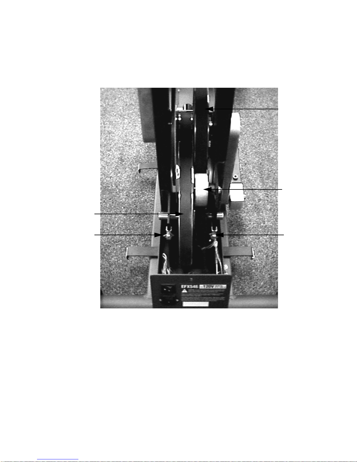
Procedure 5.4 - Inspecting and Adjusting Belt Alignment and
Tension
Procedure
1. Set the on/off switch in the “off” position, then unplug the power cord from the wall outlet.
WARNING
Before continuing with this procedure, review the Warning and Caution statements listed in
Section One, Things You Should Know.
2. Remove the rear cover as described in Procedure 7.1.
3. Remove both stairarms as described in Procedure 7.24.
4. Operate the unit by rapidly rotating a crankarm by hand. As the unit operates watch the
drive belts for proper alignment. The belts should operate parallel to each other and the
belts should maintain even spacing.
5. If the belts are not correctly aligned...
THEN... OTHERWISE...
Continue with the next step. Skip to step 13
6. Refer to Diagram 5.4 for the following belt alignment steps.The right and left tension bolts
have locking tabs. If necessary, use pliers to bend the locking tabs out of the way so that the
bolts can be turned.
7. If the step up pulley belt is out of alignment to the right, continue with step 9.
8. If the step up pulley belt is out of alignment to the left, continue with step 11.
9. Turn the left tension bolt 1/4 turn clockwise, then repeat ste p 4. If turning the left adjust ment
bolt 1/4 of a turn was not sufficient, turn the right tension bolt 1/4 of a turn counterclockwise.
10. Repeat step 8, alternating between the left and right tension bolts until the alignment is
correct. Continue with step 13.
11. Turn the right tension bolt 1/4 of a turn clockwise, then repeat step 4. If turning the rightt
adjustment bolt 1/4 of a turn was not sufficient, turn the left tension bolt 1/4 turn
counterclockwise.
12. Repeat step 11, alternating between the right and left tension bolts until the alignment is
correct.
Page 27
C546 Elliptical Fitness Crosstrainerl
Page 27
13. Belt tension must now be checked and if necessary corrected. Remember, if it is necessary
to change the belt tension, the belt alignment must be maintained.
Diagram 5.4 - Drive Unit
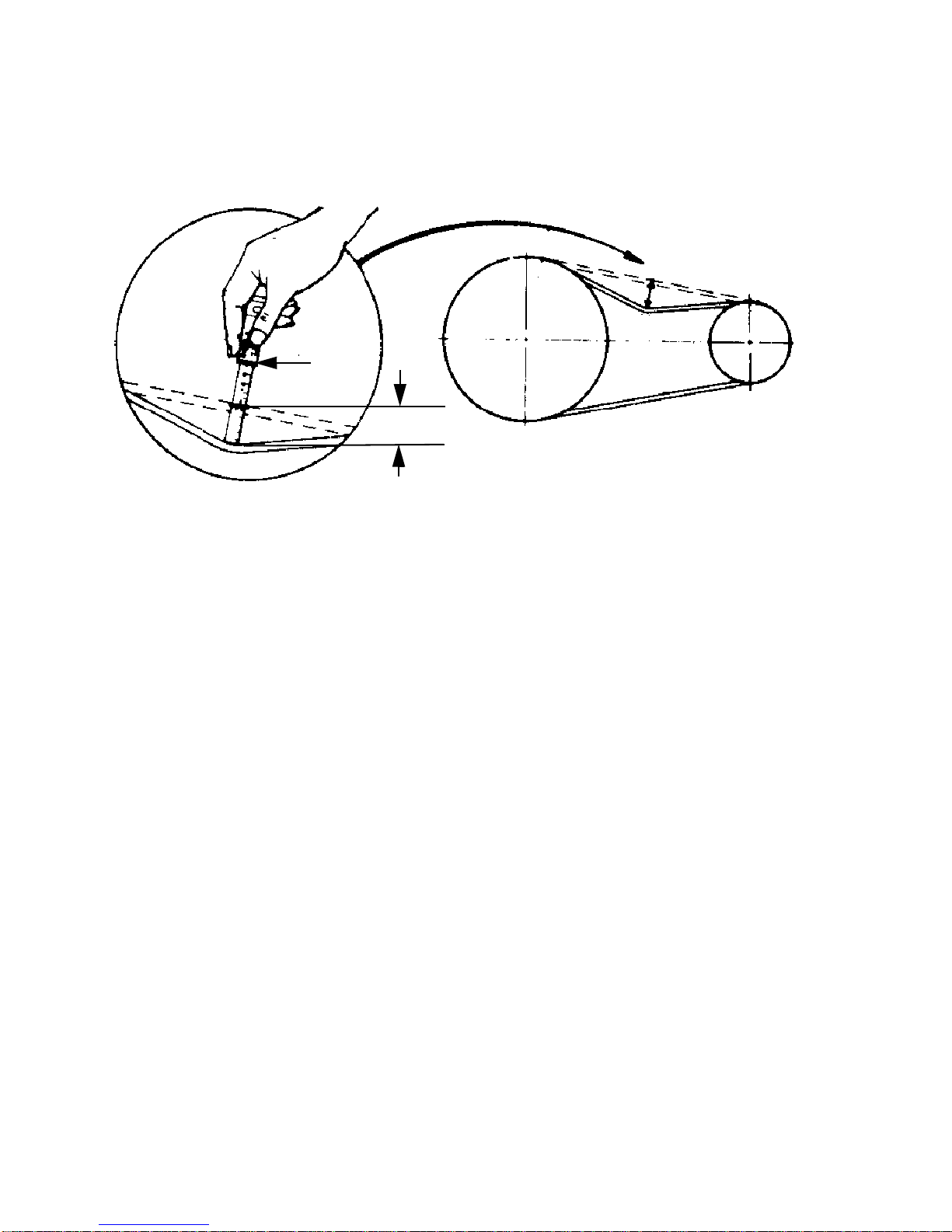
14. Place a belt gauge (McMaster-Carr 6160K12 or Grainger 3HX33) in the middle of the step
up belt and the center of the belt span (see Diagram 5.5). Lay a straight edge along the
length of the belt and beside the belt gauge. Slide one of the o-rings up against the shoulder
of the belt gauge. Press downward on the belt gauge, causing the belt to deflect. Read the
deflection on the belt gauge at the edge of the straight edge. Deflect the belt 1/4”. Read the
tension across the top edge of the o-ring. If the belt is correctly tensioned the gauge will
read between 19 and 21 pounds.
15. If the tension in step 13 is correct skip to step 18. Otherwise continue with the next step.
Input
Pulley
Stub
Tensioner
Step Up
Pulley
Tension Bolt
Tension Bolt
Left
Right
Page 28
C546 Elliptical Fitness Crosstrainer
Page 28
Diagram 5.5 - Measuring Belt tension
16. If the locking tabs on the right and left tension bolts have not been straight ened, use pliers to
bend the locking tabs out of the way so that the bolts can be turned.
IF... THEN...
The belt tensioning gauge reads Turn both tension bolts
less than 19 pounds clockwise, in equal quarter-turn
increments, until the belt tensioning
gauge reads 19 - 21 pounds @1/4” deflection.
The belt tensioning gauge reads Turn both tension bolts
more than 21 pounds counterclockwise, in equal
quarter-turn increments, until the belt
tensioning gauge reads 19 - 21 pounds @ 1/4”
deflection.
17. Verify that the belt alignment is still correct by performing the procedure in step 4.
18. When both the step pulley tension and alignment are correct, use pliers to bend the tension
bolt locking tabs into the “locking” position.
19. The input pulley tension must now be checked and corrected, if necessary. There is not
sufficient room to use the belt tension gauge to set the input pulley belt tension. It will be
necessary to use the correctly tensioned step up belt as a comparison to set the input belt
tension.
20. Using your finger, press in on the center of the step up pulley belt to get a feeling of how
much pressure it takes to deflect the belt a 1/4”.
20 lbs
1/4”
Page 29

C546 Elliptical Fitness Crosstrainerl
Page 29
21. Using your finger, press in on the center of the lower span of the input belt. Compare the
pressure required to deflect the input belt to the pressure required to deflect the step up belt.
Diagram 5.6 - Stub Tensioner
22. Loosen the stub tensioner axle nut slightly. Turn the stub tensioner adjustment bolt
clockwise to increase or counterclockwise to decrease the input belt tension.
23. When the input belt tension is correct, torque the stub tensioner nut to 200 in/lbs. Replace
the stairarms per Procedure 7.24.
24. Check the operation of the unit as described in Section Four, then re-install the rear cover
as described in Procedure 7.1
Stub
Tensioner
Stub Tensioner
Axle Nut
Stub Tensioner
Adjustment Bolt
Page 30

C546 Elliptical Fitness Crosstrainer
Page 30
Procedure 6.1 - Troubleshooting the Lower and Upper
Interconnect Cables
Anti-static kits can be ordered from Precor (part number 20024-101).
Troubleshooting the Upper Interconnect Cable
Note:
There are three different interconnect cable combinations that were used on the C546. Units with
serial numbers starting with 4H or 5V manufactured prior to Feb. 8, 1999 used an upper and
lower ribbon cable. Units with serial numbers starting with 4H or 5V manufactured after
Feb. 8, 1999 used a single ribbon cable. Units with serial numbers starting with 9A, 9B, 75 or 9K
use an upper and lower telephone cable (RJ45). For units with serial numbers starting with 4H or
5V manufactured prior to Feb. 8, 1999 start with step 1. For units with serial numbers starting
with 4H or 5V manufactured after Feb. 8, 1999 start with step 22. For units with serial numbers
starting with 9A, 9B, 75 or 9K manufactured start with step 31.
Version 1 units, manufactured prior to Feb. 8, 1999
1. Set the on/off switch in the “off” position.
WARNING
Before continuing with this procedure, review the Warning and Caution statements listed in
Section One, Things You Should Know.
2. Attach the anti-static wrist strap to your arm, then connect the ground lead of the wrist stra p
to the units frame.
3. Remove the interconnect cable cover. (See Diagram 7.2)
4. Remove the rear cover. For convenience the upper interconnect cable is the cable that
attaches to the upper PCA and the lower interconnect ca ble is the cable that con nects to the
lower PCA.
5. Lay the unit on it’s side. There is an access hole in the bottom of the main frame tube that
allows access to the junction of the upper and lower interconnect cables. (Se e Diag ram 7 .6)
6. Disconnect the upper interconnect cable from the upper PCA and the lower interconnect
cable.
7. Connect a known good upper interconnect cable from the lower interconnect cable to the
upper PCA. Route the cable outside of the unit at this time.
8. Check operation as described in Section Four.
9. If the unit operated correctly when the new interconnect cable was installed, the original
Page 31

C546 Elliptical Fitness Crosstrainerl
Page 31
interconnect cable is bad. Install a new interconnect cable per Procedure 7.7. If the unit
does not operate properly, continue with the next step.
10. Reconnect the original upper interconnect cable to the upper PCA.
Troubleshooting the Lower Interconnect Cable
11. Remove the shield from the lower PCA.
12. Remove the interconnect cable from the lower PCA.
13. Connect a known good lower interconnect cable between the lower PCA and the upper
interconnect cable.
14. Check operation as described in Section Four.
15. If the unit operated correctly when the spare lower interconnect cable was installed, the
original interconnect cable is bad. Install a new interconnect cable per Procedure 7.7. If the
unit does not operate properly, continue with the next step.
16. Reconnect the original lower interconnect cable to the lower PCA.
17. Reconnect the lower interconnect cable to the upper interconnect cable.
18. Replace the lower PCA shield.
19. Replace the rear cover.
20. Replace the interconnect cable cover.
21. Check operation as described in Section Four.
Version 1 units, manufactured after Feb. 7, 1999
22. Set the on/off switch in the “off” position.
23. Attach the anti-static wrist strap to your arm, then connect the ground lead of the wrist strap
to the units frame.
24. Remove the interconnect cable cover. (See Diagram 7.2)
25. Remove the rear cover.
26. Disconnect the interconnect cable from the upper PCA and from the lower PCA.
27. Connect a known good upper interconnect cable from the lower PCA to the upper PCA.
Route the cable outside of the unit at this time.
28. Check operation as described in Section Four.
Page 32

C546 Elliptical Fitness Crosstrainer
Page 32
29. If the unit operated correctly when the new interconnect cable was installed, the original
interconnect cable is bad. Install a new interconnect cable per Procedure 7.7. If the unit
does not operate properly, continue with the next step.
30. Reconnect the original upper interconnect cable to the upper PCA.
Version 2,3
31. Set the on/off switch in the “off” position.
32. Attach the anti-static wrist strap to your arm, then connect the ground lead of the wrist stra p
to the units frame.
33. Remove the interconnect cable cover. (See Diagram 7.2)
34. Remove the rear cover. For convenience the upper interconnect cable is the cable that
attaches to the upper PCA and the lower interconnect ca ble is the cable that con nects to the
lower PCA.
35. Connect a known good upper interconnect cable from the lower interconnect cable to the
upper PCA. Route the cable outside of the unit at this time.
36. Check operation as described in Section Four.
37. If the unit operated correctly when the new interconnect cable was installed, the original
interconnect cable is bad. Install a new interconnect cable per Procedure 7.5. If the unit
does not operate properly, continue with the next step.
38. Reconnect the original upper interconnect cable to the upper PCA.
Troubleshooting the Lower Interconnect Cable
39. Remove the shield from the lower PCA.
40. Remove the interconnect cable from the lower PCA.
41. Connect a known good lower interconnect cable between the lower PCA and the upper
interconnect cable.
42. Check operation as described in Section Four.
43. If the unit operated correctly when the spare lower interconnect cable was installed, the
original interconnect cable is bad. Install a new interconnect cable per Procedure 7.7. If the
unit does not operate properly, continue with the next step.
44. Reconnect the original lower interconnect cable to the lower PCA.
45. Reconnect the lower interconnect cable to the upper interconnect cable.
Page 33

C546 Elliptical Fitness Crosstrainerl
Page 33
46. Replace the lower PCA shield.
47. Replace the rear cover.
48. Replace the interconnect cable cover.
49. Check operation as described in Section Four
Page 34

C546 Elliptical Fitness Crosstrainer
Page 34
Procedure 6.2 - Troubleshooting the Keypad and Upper PCA
(version 1)
If the function keys on the electronic console are unresponsive, the problem may be either the
upper PCA or keypad. This troubleshooting procedure gives you the information you need to
determine which of these components is malfunctioning.
Procedure
1. Set the circuit breaker in the “off” position.
WARNING
Before continuing with this procedure, review the Warning and Caution statements listed in
Section One, Things You Should Know.
2. Remove the screws that secure the upper display assembly to the upper handrail. Carefully,
pull some excess interconnect cable out from the targa upright. Rotate the display housing,
so that the rear of the upper PCA is facing upward, and set the display housing on the upper
handrail.
3. Attach the wrist strap to your arm, then connect the ground lead of the wrist strap to the
treadmill frame.
Diagram 6.1 - Upper PCA
J4 Connector
Prom
#1
Page 35

C546 Elliptical Fitness Crosstrainerl
Page 35
4. Set the voltmeter to a range that will conveniently read +6 Vdc.
5. Set the circuit breaker in the “on” position.
6. Use a DVM, set for DC volts, and read between pin 6 of J4 and the each of the pins in Table
6.1 (no keys pressed) and Table 6.2 (with the appropriate key pressed)...
Table 6.1. - Voltage Test Points (Function Keys Not Pressed)
PLACE THE POSITIVE LEAD OF THE THE VOLTMETER SHOULD READ...
VOLTMETER ON...
Pin 3 of J4 5.25 Vdc ± 50 mVdc
Pin 4 of J4 5.25 Vdc ± 50 mVdc
Pin 5 of J4 5.25 Vdc ± 50 mVdc
Pin 7 of J4 5.25 Vdc ± 50 mVdc
Pin 8 of J4 5.25 Vdc ± 50 mVdc
Pin 9 of J4 5.25 Vdc ± 50 mVdc
Pin 10 of J4 5.25 Vdc ± 50 mVdc
Table 6.2. - Voltage Test Points (Function Keys Pressed)
PLACE THE POSITIVE AT THE DISPLAY THE VOLTMETER SHOULD
VOLTMETER LEAD ON... ENCLOSURE, PRESS... READ BETWEEN...
Pin 3 of J4 ENTER 0 Vdc and 500 mVdc
Pin 4 of J4 CROSSRAMP
▼ 0 Vdc and 500 mVdc
Pin 5 of J4 CROSSRAMP
▲ 0 Vdc and 500 mVdc
Pin 7 of J4 PAUSE 0 Vdc and 500 mVdc
Pin 8 of J4 RESISTANCE
▼ 0 Vdc and 500 mVdc
Pin 9 of J4 RESISTANCE
▲ 0 Vdc and 500 mVdc
Pin 10 of J4 QUICK START 0 Vdc and 500 mVdc
7. If the voltage readings match those listed in Tables 6.1 and 6.2 and one or more keys d o not
function, replace the upper PCA.
8. If the voltage readings in Table 6.1 are incorrect, disconnect the keypad cable from the key
pad connector and repeat the voltage measurements in 6.1. If the voltage readings are now
correct, replace the display housing (keypad). If the voltage readings are still incorrect,
replace the upper PCA.
9. If the voltage readings in Table 6.1 are correct and one or more voltage readings in Table
6.2 are incorrect, replace the display housing (keypad).
10. Set the circuit breaker in the “off” position.
11. If necessary, carefully re-connect the keypad cable to the keypad connector.
12. Remove the ground lead of the wrist strap from the treadmill frame, then remove the wrist
strap from your arm.
Page 36

C546 Elliptical Fitness Crosstrainer
Page 36
13. Position the display enclosure on the display plate. Install the screws that secure the display
enclosure to the display plate.
14. Check the operation of the treadmill as described in Section Three of this appendix
Page 37

C546 Elliptical Fitness Crosstrainerl
Page 37
Procedure 6.3 - Troubleshooting the Keypad and Upper PCA
(version 2,3)
If the function keys on the electronic console are unresponsive, the problem may be either the
upper PCA or keypad. The keys on this unit are touch sensitive keys. It is necessary to use the
keypad diagnostics to troubleshoot the key functions.
Procedure
1. Set the on/off switch in the “off” position.
WARNING
Before continuing with this procedure, review the Warning and Caution statements listed in
Section One.
2. Attach the anti-static wrist strap to your arm, then connect the ground lead of the wrist strap
to the units frame.
3. If the EFX powers up and functions normally until a particular key(s) is pressed, skip to step
12.
4. If a “key depressed” message is immediately displayed when the EFX is powered up,
continue with the next step.
5. This condition may be caused by either the keypad or upper PCA. Set the on/off switch in
the “off” position.
6. Remove the four screws that fastens the display housing front panel to the display housing
backing plate. These screws are located on the rear of the display housing backing plate.
7. Lift the display housing front panel off of the display housing backing plate. Remove the
keypad connector from the upper PCA. See Diagram 6.2.
Page 38

C546 Elliptical Fitness Crosstrainer
Page 38
Diagram 6.2 - Upper PCA & Keypad
8. Set the on/off switch in the “on” position.
9. If a “key depressed” message is immediately displayed when the EFX is powered up,
replace the upper PCA.
10. If a “key depressed” message is not displayed when the EFX is powered up, replace the
display housing front panel. The display housing front panel is equipped with the keypad.
11. If you have performed all of the procedures above and have been unable to correct the
problem, call Precor customer service.
12. Access the diagnostics program per procedure 3.2. If the key(s) necessary to access the
diagnostic program is not functioning, skip to step 14.
13. Test the keypad per Procedure 3.2, step 4.
14. If all of the keys test good, the problem may be user error or a key function that is normally
disabled during a particular user program.
15. If one or more keys do not function correctly, either the keypad (display housing) or upper
PCA could be defective. Replace the display and repeat step 12. If the display housing did
not correct the problem, re-install the original display housing and replace the upper PCA.
16. If you have performed all of the procedures above and have been unable to correct the
problem, call Precor customer service.
Upper PCA
Keypad
Connector
Keypad
Page 39

C546 Elliptical Fitness Crosstrainerl
Page 39
Procedure 6.4 - Troubleshooting the Speed Sensor
Circuit Description
The speed sensor is a hall effect sensor. A magnet is mounted on the right hand crankarm and
passes the hall effect sensor once per revolution. The output from the speed sensor is a 5 Vdc
square wave, the frequency of which indicates the operating speed. When a square wave output
is not being generated by the speed sensor the system assumes the unit is not in use and
removes resistance from the eddy current magnet system.
WARNING
Before continuing with this procedure, review the Warning and Caution statements listed in
Section One, Things You Should Know.
Procedure
1. Remove the rear cover. Plug the unit into a wall outlet and set the on/off switch in the “on”
position. Set the unit in the manual program and operate the unit. If a stride rate is not
displayed, the speed sensor is not operative. We shall use the presence of a stride rate to
determine when the speed sensor is functioning normally.
2. A magnet must be installed in the crankarm that passes the speed sensor with it’s south
pole facing the speed sensor. If the stride rate is not being displayed in step 1, verify that a
magnet is installed in the crankarm associated with the speed sensor and that the south
pole faces outward. The magnet polarity may be checked with another magnet with known
poles or a compass. The north pole of the test magnet or the south facing needle sho uld be
attracted to the speed sensor magnet.
3. Using a DC voltmeter, measure the voltage between terminal 1 (red wire) and terminal 5
(black wire) on the speed sensor connector. The measurement should be approximately 5
Vdc. If the voltage is correct, skip to step 5. If the voltage is missing or significantly low,
disconnect the speed sensor connector from the speed sensor and repeat the measurement
on the connector. If the voltage is now correct, replace the speed sensor. If the voltage is
still missing or significantly low, continue with step 4.
4. Repeat the measurements in step 3 at terminals 1 and 5 of J8 on the lower PCA. If the
voltage is missing or significantly low, replace the lower PCA. If the voltage is now correct,
replace the speed sensor assembly.
5. Using a DC voltmeter, measure the voltage between terminal 1 (red wire) and terminal 2
(blue/white wire) on the speed sensor connector. Slowly rotate the flywheel as you monitor
the voltage. The measurement should switch between approximately 0.5 Vdc and
approximately 4.25 Vdc. If the voltage is correct, skip to step 6. If the voltage does not
switch (the voltage is constantly low or high as the flywheel is slowly rotated), replace the
speed sensor. If the voltage switches correctly, but the stride rate is still not displayed when
the unit is operated, replace the lower PCA.
Page 40

C546 Elliptical Fitness Crosstrainer
Page 40
6. Repeat the measurement in step 5 at terminals 1 and 2 of J8 on the lower PCA. If the
voltage is missing or significantly low, replace the speed sensor assembly.
7. If you have performed all of the above tests and the stride rate is not displaye d when the unit
is operated, there are three parts that could cause the problem. There are not any good
tests to check these parts other than substituting a known good part. They are lower PCA,
ribbon cable and upper PCA. Replace only one part at a time. If the new part does not
correct the problem, replace the original part.
8. If you have performed all of the above tests and the speed sensor is still not functioning, call
Precor Technical Support.
Page 41

C546 Elliptical Fitness Crosstrainerl
Page 41
Procedure 6.5 - Troubleshooting the Lift System
Note:
The lift motor is disabled when the EFX is not being used. The speed sensor must detect motio n
in order for lift operation to be enabled. In the following procedures, when lift motor movement is
being tested the stairarms must be in motion. Before performing this procedure, ensure that the
speed sensor is operating normally per Procedure 6.4.
Note:
On version 1 units manufactured prior to August 16, 1998 a single lift connector (J4) was used.
On subsequent units the lift motor wiring is in the J3 connector and the lift potentiometer wiring is
in the J4 connector. This text will use the connections used on current production units. For
version 1 units manufactured prior to August 16, 1998, convert the lift connections as shown:
CONNECTION 8/16/98 AND LATER
CONNECTION PRIOR TO 8/16/98
J3 terminal 1 J4 terminal 1
J3 terminal 2 J4 terminal 2
J3 terminal 3 J4 terminal 3
J4 terminal 1 J4 terminal 4
J4 terminal 2 J4 terminal 5
J4 terminal 3 J4 terminal 6
1. If the lift motor will not move skip to step 7. If the lift motor moves and an error occurs
continue with step 2.
2. Access the diagnostics program per Procedure 3.2 and proceed to the lift calibration portion
of the diagnostics program. If the lift calibration number is 0 or 255 skip to step 3. Operate
the lift, if the lift calibration number does not increment as the lift moves, skip to step 3. If the
calibration number increments as the lift moves, re-calibrate the lift per Procedure 5.3. If recalibration does not correct the problem, continue with step 3.
3. Set the on/off switch in the “off” position. Using an ohmmeter, measure between terminal 1
(brown or green wire) and terminal 3 (orange wire) of the J4 connector on the lower PCA.
The measurement should be approximately 10 KΩ (or 1KΩ depending on manufacturer). If
the measurement is open (∞) or significantly high or low, replace the lift motor.
4. Using an ohmmeter, measure between terminals 1 and 2 of J4 and measure between 2 and
3 of J4 on the lower PCA. The two measurements should total approximately 10 KΩ (or 1KΩ
depending on manufacturer). If the measurement is open (∞) or significantly high or low,
replace the lift motor.
5. If you have performed all of the above tests and an error still occurs when the lift motor
operates, there are three parts that could cause the problem. There are not any good tests
to check these parts other than substituting a known good part. They are lower PCA, ribbon
cable and upper PCA. Replace only one part at a time. If the new part does not correct the
problem, replace the original part.
Page 42

C546 Elliptical Fitness Crosstrainer
Page 42
6. If you have performed all of the above tests and the lift system is still not functioning, call
Precor Technical Support.
7. Set the circuit breaker in the “off” position. Remove the F2 (2 amp slow blow) fuse from the
lower PCA. Measure the fuse with an ohmmeter. The measurement should be 1Ω or less. If
the fuse is good, re-insert the fuse and skip to step 9. If the fuse is open (∞) or significantly
high, replace the fuse. Before operating the lift motor it is necessary to perform a continuity
test on the lift motor.
8. Remove the J3 connector from the lower board. Using an ohmmeter, measure between
terminals 1 and 3 of J3, between terminals 1 and 2 of J3 and between terminals 2 and 3 of
J3. The measurements should be approximately 20.5Ω, 20.5Ω and 41Ω, respectively. If any
of the measurements are significantly low, replace the lift motor. If any of the readings are
open (∞) or significantly high, check the lift motor cable and connectors. Repair any wires or
connections that are bad. If the cable and connectors are good, replace the lift motor.
9. Re-insert the J3 connector in the lower PCA. Set the on/off switch in the “on” position. Using
an AC voltmeter, monitor the voltage between terminals 1 and 2 (red and white wires) of the
J3 connector. Enter the manual program and press the RAMP
▲ key. The measurement
should be approximately 120 Vac (line voltage). If the voltage is present and the lift motor
moves normally, skip to step 10. The voltage will only be present until such time as an error
occurs. If line voltage is not present skip to step 11. If line voltage is measured but the motor
does not move, replace the lift motor.
10. Monitor terminals 1 and 3 (white and black wires) of J3. Enter the manual program and
press the RAMP
▼ key. The measurement should be approximately 120 Vac (line voltage).
If the voltage is present and the lift motor moves normally skip to step 12. The voltage will
only be present until such time as an error occurs. If line voltage is measured but the motor
does not move, replace the lift motor.
11. If line voltage is not present in both steps 9 and 10, connect a dc voltmeter between TP3
and TP6 on the Lower PCA (See Diagram 7.2). The DC voltmeter should read
approximately 5.5 Vdc. Walk on the unit and press the CROSSRAMP
▼ key. The DC
voltmeter should read near 0 Vdc and the ramp should go downward. Connect a dc
voltmeter between TP4 and TP6 on the Lower PCA (See Diagram 7.2). The DC voltmeter
should read approximately 5.5 Vdc. Pedal on the unit and press the CROSSRAMP
▲ key.
The DC voltmeter should read near 0 Vdc and the ramp should go upward.
12. If all of the voltages in step 11 were correct but the ramp did not move in both directions
replace the LPCA.
13. If one or more of the voltages in step 11 were incorrect the problem is either one of the
interconnect cables or the Upper PCA. If the display does not indicate that the ramp is
moving in both directions when the appropriate CROSSRAMP key is pressed the problem is
either the Upper PCA or the keypad (display housing). Use Procedures 6.1, 6.2 and 6.3 to
determine if the problem is an interconnect cable, keypad or Upper PCA.
14. If you have performed all of the above tests and the lift system is still not functioning, call
Precor Technical Support.
Page 43

C546 Elliptical Fitness Crosstrainerl
Page 43
Procedure 6.6 - Troubleshooting the Eddy Current System
Note:
If the control circuit does not see an output from the speed sensor, it removes power from the
eddy current system. Therefore, when it is necessary to check the resistance or take voltage
measurements in the eddy current system it will be necessary to slowly turn the flywheels to
ensure that the power time out has not occurred.
WARNING
Before continuing with this procedure, review the Warning and Caution statements listed in
Section One, Things You Should Know
1. There are three typical symptoms concerning the eddy current system. No resistance
(pedaling resistance), no resistance shortly after power up and incorrect resistance. If the
problem is no resistance, continue with step 2. If the problem is no resistance shortly after
power up, test the speed sensor per Procedure 6.4. If the problem is incorrect resistance,
skip to step 7.
2. Set the on/off switch in the “on” position, enter the manual program and set the resistance at
level 10. Using a DC voltmeter, check the voltage across the magnet. The voltage should
measure approximately 29.5 Vdc. If the voltage is missing or significantly low, skip to step 4.
If the voltage is correct, continue with step 3.
3. Set the on/off switch in the “off” position. Check the magnet wiring per Diagram 8.1. If any of
the magnet wiring is reversed or incorrect the resistance will be affected. If you have
performed all of the above tests and there is still no resistance, call Precor Technical
Support.
4. Set the on/off switch in the “off” position. Using an ohmmeter, measure between the M- and
M+ terminals of the lower PCA. The measurement should be approximately 90 Ω to 110Ω. If
the measurement is open (∞), check the connections at both magnets and the lower PCA.
5. If all of the wiring connections are good and there is still no resistance, there are three parts
that could cause the problem. There are not any good tests to check these parts other than
substituting a known good part. They are lower PCA, ribbon cable and upper PCA. Replace
only one part at a time. If the new part does not correct the problem replace the original part.
6. If you have performed all of the above tests and there is still no resistance, call Precor
Technical Support.
7. If the resistance is greater than normal, the cause could be mechanical rather than
electrical. Check all moving parts in the drive section and stairarms for worn parts that could
be “binding”. Replace the appropriate parts.
8. Set the on/off switch in the “on” position, enter the manual program and set the resistance at
level 10. Using a DC voltmeter, check the voltage across the magnet. The voltage should
measure approximately 29.5 Vdc.
Page 44

C546 Elliptical Fitness Crosstrainer
Page 44
9. If the voltage is still significantly high or low, there are three parts that could cause the
problem. There are not any good tests to check these parts other than substituting a known
good part. They are lower PCA, ribbon cable and upper PCA. Replace only one part at a
time. If the new part does not correct the problem, replace the original part.
10. If you have performed all of the above tests and the resistances are still incorrect, call
Precor Technical Support.
Page 45

C546 Elliptical Fitness Crosstrainerl
Page 45
Procedure 6.7 - Upper Display does not Illuminate
(version 1)
1. Set the on/off switch in the “off” position, unplug the line cord from the wall outlet.
2. Remove the F1 and F2 fuses from the lower PCA. (See Diagram 7.4)
3. Remove the fuses from the input power module. (See Diagram 7.7)
4. Check all four fuses with an ohmmeter. They should read approximately 1Ω or less.
Replace any fuse that reads significantly high.
5. Replace the fuses in the power input module.
6. With the line cord still unplugged from the wall outlet, set the on/off switch in the “on”
position. check between the power terminals of the line cord with an ohmmeter. The
ohmmeter reading should be very high, megohms or greater.
7. If the reading is good skip to step 11, otherwise continue with the next step.
8. If the reading in step 5 is significantly low, check the wiring between the lower PCA and the
on/off switch, between the on/off switch and the input module. Replace any cut or nicked
wiring.
9. Check the line cord for nicked or cut wiring. Replace the line cord if necessary.
10. If you have performed all of the above tests and are unable to resolve the problem, contact
Precor customer support.
11. Replace the F1 (1/4 amp) fuse in the lower PCA, perform the resistance measurement in
step 6. The reading should be approximately 40-75Ω.
12. Replace the F2 (2 amp) fuse in the lower PCA, perform the resistance measurement in step
6. The reading should be approximately 40-75Ω.
13. If either of the readings in step 11 or 12 were significantly low, replace the lower PCA.
14. Plug the line cord into the wall outlet and set the on/off switch in the “on” position.
15. The green LED (D1) and the red LED (D2) should illuminate. Check between TP5 and TP6
on the lower PCA with a DC voltmeter. The reading should be approximately 5 Vdc. (See
Diagram 7.4)
16. If the reading in step 15 is good, skip to step 18. If the reading in step 15 is significantly low,
set the on/off switch in the “off” position. Disconnect the lift cable (J4) and the interconnect
cable (J5) from the lower PCA.
Page 46

C546 Elliptical Fitness Crosstrainer
Page 46
17. Set the on/off switch in the “on” position. Repeat step 15. If the reading is still significantly
low, replace the lower PCA. If the reading is now good, the problem is either the
interconnect cable or the upper PCA.
18. Substitute a known good upper PCA. If the upper PCA does not correct the problem,
troubleshoot the upper and lower interconnect cables per Procedure 6.1
19. If you have performed all of the above tests and are unable to resolve the problem, contact
Precor customer support.
Page 47

C546 Elliptical Fitness Crosstrainerl
Page 47
Procedure 6.8 - Upper Display does not Illuminate
(version 2,3)
1. Set the on/off switch in the “off” position, unplug the line cord from the wall outlet.
2. Attach the anti-static wrist strap to your arm, then connect the ground lead of the wrist strap
to the units frame.
3. Remove the F1 fuse from the lower PCA. (See Diagram 7.5)
4. Remove the fuses from the input power module. (See Diagram 7.7)
5. Check all three fuses with an ohmmeter. They should read approximately 1Ω or less.
Replace any fuse that reads significantly high.
6. Replace the fuses in the power input module.
7. With the line cord still unplugged from the wall outlet, set the on/off switch in the “on”
position. check between the power terminals of the line cord with an ohmmeter. The
ohmmeter reading should be infinity (open).
8. If the reading is good skip to step 11, otherwise continue with the next step.
9. If the reading in step 5 is significantly low, check the wiring between the lower PCA and the
on/off switch, between the on/off switch and the input module. Replace any cut or nicked
wiring.
10. Check the line cord for nicked or cut wiring. Replace the line cord if necessary.
11. If you have performed all of the above tests and are unable to resolve the problem, contact
Precor customer support.
12. Replace the F1 (1/4 amp) fuse in the lower PCA, perform the resistance measurement in
step 6. The reading should be approximately 1.0 to 1.5 megohms.
13. Replace the F2 (2 amp) fuse in the lower PCA, perform the resistance measurement in step
6. The reading should be approximately 1.0 to 1.5 megohms.
14. If either of the readings in step 11 or 12 were significantly low, replace the lower PCA.
15. Plug the line cord into the wall outlet and set the on/off switch in the “on” position.
16. The red LED (D7) and the red LED (D2) should illuminate. Check between TP11 and TP14
on the lower PCA with a DC voltmeter. The reading should be approximately 5 Vdc.
Page 48

C546 Elliptical Fitness Crosstrainer
Page 48
17. If the reading in step 15 is good, skip to step 18. If the reading in step 15 is significantly low,
set the on/off switch in the “off” position. Disconnect the interconnect cable (J5) from the
lower PCA.
18. Set the on/off switch in the “on” position. Repeat step 15. If the reading is still significantly
low, replace the lower PCA. If the reading is now good, the problem is either one of the
interconnect cables or the upper PCA.
19. Substitute a known good upper PCA. If the upper PCA does not correct the problem,
troubleshoot the upper and lower interconnect cables per Procedure 6.1
20. If you have performed all of the above tests and are unable to resolve the problem, contact
Precor customer support.
Page 49

C546 Elliptical Fitness Crosstrainerl
Page 49
Procedure 6.9 - Troubleshooting Hand Held Heart Rate
Circuit Description
The hand held heart rate system is actually a dual system, that is, it can accept a heart rate
signal from either the hand held heart rate contacts on the unit’s handlebar or from a Polar heart
rate chest strap transmitter. Refer to Diagram 6.3 and verify that no jumpers are equipped on
J13, J14, J15 or J16. Also, verify that there is a jumper equipped on the internal chest strap
setting. The internal chest strap setting is the two left hand pins on the three pin connector as
shown below in Diagram 6.3. These settings allow the heart rate system to operate on the
internal chest strap receiver with the chest strap heart rate priority. That is, if both a chest strap
and hand heart rate signal is being received, the system will accept the chest strap signal and
ignore the hand held signal. If a chest strap signal is not being received, the system will accept
the hand held signal.
Note:
There are four typical failure modes for the hand held/chest strap heart rate system. They are:
1 - hand held is normal - no chest strap reading; 2 - no hand held reading - chest strap normal;
3 - no hand held or chest strap reading; 4 - constant or intermittent readings when neither hand
held or chest strap are in use.
Diagram 6.3 - Hand held/chest strap heart rate PCA
Normal hand held reading - No chest strap reading
1. Set the on/off switch in the “on” position and access the diagnostic program (Procedure 3.3).
Advance to the heart rate display portion of the diagnostic program. Verify that a chest strap
signal is not being accepted with either a Polar heart rate test transmitter or a known good
chest strap transmitter. If this reading is good, skip to step 3.
2. Using a Polar heart rate test receiver, verify the operation of the chest strap transmitter
furnished with the unit. If the Polar heart rate test receiver does not receive a signal, replace
the chest strap transmitter.
J13
J14
J15
J16
5 Vdc
Gnd
Lower Right
Upper Right
Upper Left
Lower Left
HR Output
o o o
Internal Chest
Strap Setting
Page 50

C546 Elliptical Fitness Crosstrainer
Page 50
3. Set the on/off switch in the “off” position and remove the display housing.
4. Verify the internal chest strap setting is set as shown in Diagram 6.3. Verify that a ferrite
bead is installed on the heart rate PCA to upper PCA cable.
5. If the above procedures did not correct the problem, replace the heart rate PCA.
No hand held reading - Normal chest strap reading
6. Set the on/off switch in the “on” position and access the diagnostic program (Procedure 3.3).
Advance to the heart rate display portion of the diagnostic program. Verify that a hand held
signal is not being accepted by firmly grasping both the right and left hand held contacts on
the handlebars. Cover as much of the contact surface area with your hands as possible
(without moving your hands), you should receive a heart rate reading within ten seconds.
7. If a hand held signal is not being accepted, set the on/off switch in the off position.
8. Temporarily, install a spare jumper on J14 of the heart rate PCA (hand held priority). Set the
on/off switch in the “on” position and repeat the procedure in step 6.
9. If the hand held signal is now being accept, something in the near vicinity is radiating RF
(radio frequency) energy that is being received by the chest strap portion of the heart rate
PCA. Disabling the chest strap signal proves that it is radiated energy that is causing the
problem.
10. If a hand held signal still not being accepted, skip to step 13.
11. The source of the radiated energy must be determined and relocated so that it no longer
affects the heart rate PCA. Televisions, cell phones, Cardio-theatre receivers, etc. are
possible sources of radiated energy.
12. Set the on/off switch in the “off” position, and remove the temporary jumper from J14 of the
heart rate PCA. Re-locate all potential sources of radiation. Set the on/off switch in the “on”
position and repeat the procedure in step 6.
13. Set the on/off switch in the “on” position and access the diagnostic program (Procedure 3.3).
Advance to the heart rate display portion of the diagnostic program. Verify that a hand held
signal is not being accepted by firmly grasping both the right and left hand held contacts with
the opposite hands, right hand on the left handlebar contacts and left hand on the right
handlebar contacts. Cover as much of the contact surface area with your hands as possible,
you should receive a heart rate reading within ten seconds. If a hand held signal is still not
being accepted, skip to step 15.
14. If a hand held signal was accepted in step 13, the hand held contact wiring is reversed. The
end of the wire harness that connects to the hand held contacts in the handlebar is
segregated into two groups. One group has blue shrink wrap around it and the other group
has black shrink wrap around it. The “blue” group must go to the right hand contacts and the
“black” group must go to the left hand contacts. In both groups the black wire must go to the
lower contact and the red wire must go to the upper contact. If necessary, rewire the hand
held contacts as described above and test as described in step 6.
Page 51

C546 Elliptical Fitness Crosstrainerl
Page 51
15. Set the on/off switch in the “off” position. Refer to Diagram 6.3 for the following
measurements. With an ohmmeter measure between the “lower right contact” pin on the J1
connector and the lower right hand held heart rate contact on the handlebar. The reading
should be 1 Ω or less. Measure between the “upper right contact” pin on the J1 connector
and the upper right hand held heart rate contact on the handlebar. The reading should be 1
Ω or less. Measure between the “upper left contact” pin on the J1 connector and the upper
left hand held heart rate contact on the handlebar. The reading should be 1 Ω or less.
Measure between the “lower left contact” pin on the J1 connector and the lower left hand
held heart rate contact on the handlebar. The reading should be 1 Ω or less. If any of the
above readings are greater than 1 Ω, replace the heart rate PCA to handlebar wire harness.
No hand held reading - No chest strap reading
16. Set the on/off switch in the “on” position and access the diagnostic program (Procedure 3.3).
Advance to the heart rate display portion of the diagnostic program. Verify that neither a
chest strap signal or a hand held signal is being accepted with either a heart rate test
transmitter or a chest strap transmitter.
17. Check the plug/connector connections on both the heart rate PCA (J4), and upper PCA (J1).
18. If neither a chest strap signal or a hand held signal is being accepted, measure between the
“ground” and “5 Vdc” pins on J4 for 5 Vdc. If 5 Vdc is present, replace the heart rate PCA.
19. If 5 Vdc is not present, remove the connector from J4 of the heart rate PCA. Measure
between the “ground” and “5 Vdc” pins of the connector (just removed from the heart rate
PCA) for 5 Vdc. If 5 Vdc is present, replace the heart rate PCA. If the 5 Vdc is not present,
measure between the corresponding pins of J1 on the upper PCA (red and black wires). If 5
Vdc is not present replace the upper PCA. If 5 Vdc is present, replace the upper PCA to
heart rate PCA cable.
Constant or intermittent readings when neither the hand held or chest strap is in use
20. Verify that a ferrite core is clamped around the heart rate PCA to upper PCA cable.
21. Constant or intermittent heart rate readings when neither heart rate system is in use is
caused by something in the near vicinity radiating RF energy that is being received by the
chest strap portion of the heart rate PCA.
22. Temporarily, install a spare jumper on J14 of the heart rate PCA (hand held priority). Set the
on/off switch in the “on” position and repeat the procedure in step 6.
23. If the hand held signal is now being accept, something in the near vicinity is radiating RF
energy that is being received by the chest strap portion of the heart rate PCA. Disabling the
chest strap signal proves that it is radiated energy that is causing the problem.
24. The source of the radiated energy must be determined and relocated so that it no longer
affects the heart rate PCA. Televisions, cell phones, Cardio-theatre receivers, etc. are
possible sources of radiated energy.
Page 52

C546 Elliptical Fitness Crosstrainer
Page 52
25. Set the on/off switch in the “off” position, and remove the spare jumper from J14 of the heart
rate PCA. Re-locate all potential sources of radiation. Set the on/off switch in the “on”
position and repeat the procedure in step 6.
Page 53

C546 Elliptical Fitness Crosstrainerl
Page 53
Procedure 7.1 - Replacing the Front or Rear Covers
Procedure
1. Set the on/off switch in the “off” position, then unplug the power cord from the wall outlet.
For version 1,2 units, continue with step 2. For version 3 units skip to step 13.
WARNING
Before continuing with this procedure, review the Warning and Caution statements listed in
Section One, Things You Should Know.
Removing and Replacing the Rear Cover (version 1, 2)
2. Remove the screws that secure the rear cover.
3. Lift and slightly spread the rear cover until it clears the unit, then set it aside.
4. When maintenance operations are complete, position the rear cover at its mounting
position.
5. Replace the screws that secure the rear cover.
Removing and Replacing the Front Cover (version 1,2)
6. Remove the screws that secure the bottom of the front cover to the cover bracket.
7. Remove the screws that secure the cover badge. The cover badge is located at the top of
the cover. Remove the cover badge.
Diagram 7.1 - Front Cover Badge
Cover
Badge
Frame
Uprights
Front
Cover
Page 54

C546 Elliptical Fitness Crosstrainer
Page 54
8. Remove the cover by sliding it between the frame uprights.
9. When maintenance operations are complete, slide the cover into place through the frame
uprights.
10. Replace and hand tighten the screws that retain the bottom of the cover to the cover
bracket.
11. Replace the cover badge. The cover badge must slide over the lift motor drive screw. If the
cover badge is not mated with the lift motor drive screw, the cover is not secured and will
vibrate when the lift is operated. Replace and tighten the cover badge screws.
12. Tighten the screws replaced in step 10.
Removing and Replacing the Rear Cover (version 3
13. Set the on/off switch in the “off” position, then unplug the power cord from the A.C. outlet.
WARNING
Before continuing with this procedure, review the Warning and Caution statements listed in
Section One, Things You Should Know.
14. The rear cover is a four piece cover; front, top, left and right sections. If the front cover
section is being removed, the frame cover must also be removed (See Diagram 7.2).
15. If you are removing either the right or left cover section, it is only necessary to remove the
four screws that fasten the cover section.
Diagram 7.2- Frame Cover
16. If you are replacing either the front or top cover section, you must first remove the left and
right cover sections and then remove the cover section being replaced.
17. If you are removing the top cover (See Diagram 7.3), remove the two phillip screws that
fasten the top cover section to the frame upright. Remove three screws that fasten the top
cover section to the rear cover support. Remove two screws that fasten the top cover
Frame
Cover
Mounting
Screw
Page 55

C546 Elliptical Fitness Crosstrainerl
Page 55
section to the front cover section.
Page 56

C546 Elliptical Fitness Crosstrainer
Page 56
18. If you are removing the front cover section, the right, left and top cover sections must be
removed first. Remove the four screws that fasten the frame cover to the frame (See
Diagram 7.2). Remove two phillips screws that fasten the bottom of the front cover section
to the frame. Lift the rear portion of the frame cover and carefully remove the front cover
section. If it is necessary to remove the frame cover, lift the rear of the frame cover, slide the
frame cover out of the ramp and remove the frame cover.
Diagram 7.3 - Top Cover Section (with right & left cover sections removed)
19. If all four cover sections have been removed, first replace the frame cover and front cover
section, then the top cover section and then the left and right cover sections as described
below.
20. Slide the tongue of the frame cover into the ramp. Lift the rear of th e frame cover an d fit the
front cover against the frame cover. Slide the front and frame covers into place as a unit.
Replace and tighten the four phillips screws that fasten the frame cover to the frame.
Replace and tighten the two phlliips screws that fasten the front cover section to the frame.
21. Set the top cover section in it’s mounting position, replace and tighten the two phillips
screws that fasten the top cover section to the frame upright. See Diagram 7.3. Replace and
tighten the three screws that fasten the top cover section to the rear cover support. Replace
and tighten the two screws that fasten the top cover section to the front cover section.
22. Set the left cover section in it’s mounting position, replace and tighten the four screws that
fasten the left cover section to the front cover section, top cover section and rear cover
support.
23. Set the right cover section in it’s mounting position, replace and tighten the four screws that
fasten the right cover section to the front cover section, top cover section and rear cover
support.
Frame
Upright
Mounting
Screw
Top Cover
Section
Front Cover
Section
Page 57

C546 Elliptical Fitness Crosstrainerl
Page 57
Removing and Replacing the Front Cover (version 3)
24. Remove the four lower front cover mounting screws (two each side) from the lower frame.
25. Remove the four upper front cover mounting screws (two each side) from the upper frame.
26. Remove both front cover halves from the unit.
27. When service is complete, set both cover halves in their mounting positions.
28. Replace the four upper front cover mounting screws (two each side) in the upper frame.
29. Replace the four lower front cover mounting screws (two each side) in the lower frame.
Page 58

C546 Elliptical Fitness Crosstrainer
Page 58
Procedure 7.2 - Replacing the Display Enclosure or Upper PCA
(version 1)
Anti-static kits (part number 20024-101) can be ordered from Precor.
Removing the Display Enclosure
1. Set the on/off switch in the “off” position.
WARNING
Before continuing with this procedure, review the Warning and Caution statements listed in
Section One, Things You Should Know.
2. Remove the screws that secure the interconnect cable cover to the bottom of the display
backing plate. Remove the interconnect cover cable. See Diagram 7.4.
3. Remove the screws that secure the reading rack to the to the display backing plate. Remove
the reading rack.
4. Remove the screws that secure the display housing to the display backing plate.
5. Attach the wrist strap to your arm, then connect the ground lead of the wrist strap to the EFX
frame.
6. Disconnect the interconnect cable from the upper PCA.
7. If you are going to re-install the display enclosure without replacing the upper PCA...
THEN... OTHERWISE...
Skip to Step 10. Continue with the next step.
Removing and Replacing the Upper PCA
8. Carefully disconnect the keypad cable from the upper PCA.
9. Remove the screws that secure the upper PCA to the display enclosure.
Page 59

C546 Elliptical Fitness Crosstrainerl
Page 59
Diagram 7.4 - Upper Handlebar Assembly
10. Reposition the upper PCA at its mounting location on the display enclosure (refer to
Diagram 7.4). Replace and tighten the upper PCA mounting screws.
11. Reconnect the keypad cable to the upper PCA.
12. Reconnect the interconnect cable to the upper PCA.
13. Remove the ground lead of the wrist strap from the EFX frame, then remove the wrist strap
from your arm.
14. Position the display enclosure on the display plate. Replace and tighten the display
mounting screws.
15. Reposition the reading rack, replace and tighten the reading rack mounting screws.
16. Reposition the interconnect cable cover, replace and tighten the interconnect cable cover
mounting screws.
17. Check operation as described in Section Four.
Interconnect
Cable Cover
Display
Housing
Reading
Rack
Upper PCA
Display
Backing Plate
Page 60

C546 Elliptical Fitness Crosstrainer
Page 60
Procedure 7.3 - Replacing the Display Enclosure or Upper PCA
(version 2,3)
Anti-static kits (part number 20024-101) can be ordered from Precor.
The keyboard is part of the display housing front panel. If the keyboard is not functioning
properly, replace the display housing front panel.
Removing the Display Housing Front Panel
1. Set the on/off switch in the “off” position.
WARNING
Before continuing with this procedure, review the Warning and Caution statements listed in
Section One, Things You Should Know.
2. Attach the anti-static wrist strap to your arm, then connect the ground lead of the wrist stra p
to the units frame.
3. Remove the four screws that secure the display housing front panel to the display backing
plate.
4. Attach the wrist strap to your arm, then connect the ground lead of the wrist strap to the EFX
frame.
5. Disconnect the upper interconnect cable from the upper PCA (connector J5).
Removing and Replacing the Upper PCA
6. Carefully disconnect the keyboard cable from the upper PCA (connector J2).
7. Remove the four screws that secure the upper PCA to the display housing front panel.
Note:
Package the upper PCA in an anti-static bag and document the problem as described in
Procedure 3.5, Documenting Software Problems.
Page 61

C546 Elliptical Fitness Crosstrainerl
Page 61
Diagram 7.5 - Display Housing Front Panel, Rear View
8. Position the upper PCA at its mounting location on the display housing front panel (refer to
Diagram 7.5). Replace and tighten the upper PCA mounting screws.
9. Reconnect the keyboard cable to the upper PCA.
10. Reconnect the upper interconnect cable to the upper PCA.
11. Remove the ground lead of the wrist strap from the EFX frame, then remove the wrist strap
from your arm.
12. Position the display enclosure on the display plate. Replace and tighten the display
mounting screws.
13. Check operation as described in Section Four.
Upper PCA
Keyboard
Connector
Interconnect
Cable
Connector
Page 62

C546 Elliptical Fitness Crosstrainer
Page 62
Procedure 7.4 - Replacing the PROM
Anti-static kits (part number 20024-101) can be ordered from Precor.
1. The PROM and the associated printed circuit assembly (PCA) are static sensitive. Antistatic devices must be used and all anti-static precautions must be followed during this
procedure.
2. Remove the printed circuit assembly per its associated procedure.
3. Currently we are using two styles of IC software packages. they are a 28 pin dual in line
package (DIP28) and a forty-four pin square package (PLCC44). Each of these packages
should be removed with a proper IC removal tool (see the illustrations below)
4. The IC’s may inserted into their socket by hand by carefully aligning the n otch on the IC with
the notch on the IC socket and carefully pressing the IC into its socket. See the illustrations
below for the alignment notches. Care must be taken that the IC legs on a DIP28 are all
aligned in the socket to prevent the legs from bending when inserted. The PLCC44 IC must
be carefully aligned squarely in its socket or it will not insert. Do not force the IC into its,
socket. If it does not insert easily, remove the it and re-align it in its socket.
DIP28 removal tool
PLCC44 removal tool
Notch
Notch
DIP28
Notch
Notch
PLCC44
Page 63

C546 Elliptical Fitness Crosstrainerl
Page 63
Procedure 7.5 - Replacing the Lower PCA (version 1)
Removing the Lower PCA
1. Set the on/off switch in the “off” position.
WARNING
Before continuing with this procedure, review the Warning and Caution statements listed in
Section One, Things You Should Know.
2. Remove the rear cover as described in Procedure 7.1.
3. Attach the wrist strap to your arm, then connect the ground lead of the wrist strap to the EFX
frame.
4. Remove the shield from the lower PCA.
5. Disconnect the cables from the lower PCA.
6. Remove the screws that secure the lower PCA.
Diagram 7.6 - Lower PCA
F2
1/4A Fuse
F1
J3
J8
TP5, TP6
J4
J5
TP3, TP4
2A Fuse
Page 64

C546 Elliptical Fitness Crosstrainer
Page 64
Replacing the Lower PCA
7. Position the replacement lower PCA at its mounting position.
8. Install the screws that secure the lower PCA.
9. Connect the cables you disconnected in Step 5.
10. Install the lower PCA shield.
11. Remove the ground lead of the wrist strap from the EFX frame, then remove the wrist strap
from your arm.
12. Re-install the rear cover as described in Procedure 7.1, then check the operation of the EFX
546 as described in Section Four.
Page 65

C546 Elliptical Fitness Crosstrainerl
Page 65
Procedure 7.6 - Replacing the Lower PCA (version 2,3)
Removing the Lower PCA
1. Set the on/off switch in the “off” position.
WARNING
Before continuing with this procedure, review the Warning and Caution statements listed in
Section One, Things You Should Know.
2. Remove the rear cover.
3. Attach the wrist strap to your arm, then connect the ground lead of the wrist strap to the EFX
frame.
4. Remove the shield from the lower PCA.
5. Disconnect the cables from the lower PCA.
6. Remove the screws that secure the lower PCA.
Diagram 7.7 - Lower PCA
D2 LED
D7 LED
J5 Connector
F1 Fuse
Page 66

C546 Elliptical Fitness Crosstrainer
Page 66
Replacing the Lower PCA
7. Position the replacement lower PCA at its mounting position.
8. Install the screws that secure the lower PCA.
9. Connect the cables you disconnected in Step 5.
10. Install the lower PCA shield.
11. Remove the ground lead of the wrist strap from the EFX frame, then remove the wrist strap
from your arm.
12. Re-install the rear cover, then check the operation of the C556 as described in Section Four.
Page 67

C546 Elliptical Fitness Crosstrainerl
Page 67
Procedure 7.7 - Replacing the Lower and/or Upper Interconnect
Cables
Before you install a new interconnect cable, ensure that the interconnect cable is defective as
described in Procedure 6.1.
Procedure
1. Set the on/off switch in the “off” position.
WARNING
Before continuing with this procedure, review the Warning and Caution statements listed in
Section One, Things You Should Know.
2. Attach the wrist strap to your arm, then connect the ground lead of the wrist strap to the EFX
frame.
Note:
There are three different interconnect cable combinations that were used on the C546. Version 1
units manufactured prior to Feb. 8, 1999 used an upper and lower ribbon cable. Version 1units
manufactured after Feb. 7, 1999 used a single ribbon cable. Version 2,3 units used an upper and
lower telephone cable (RJ45). For version 1 units manufactured prior to Feb. 8, 1999 start with
step 3. For version 1 units manufactured after Feb. 7, 1999, start with step 20. For version 2,3
units start with step 29.
Replacing the Upper Interconnect Cable
3. If you are replacing the lower interconnect cable, skip to step 12.
4. Remove the display housing per Procedure 7.2, steps 2 to 6.
5. Lay the EFX on it’s side. The upper and lower interconnect cables are connected in the
main frame tube. Locate the access hole in the main frame tube. (See Diagram 7.8).
Diagram 7.8 - Interconnect Cable Access
Page 68

C546 Elliptical Fitness Crosstrainer
Page 68
6. Two cables are in the main frame tube. The lift motor cable and the interconnect cable(s).
Locate the interconnect cable connectors in the access hole and disconnect the
interconnect cables.
7. Tape the end of the replacement interconnect cable with the small (16 pin) connector to the
upper end of the old interconnect cable (display housing end).
8. Carefully pull the old interconnect cable out of the bottom access hole while feeding the new
interconnect cable into the unit. When the new cable is fully into the unit, remove the tape
and discard the old interconnect cable. Connect the two interconnect cables and push them
into the access hole.
9. Replace the display housing per Procedure 7.2, steps 14 to 18.
10. Remove the ground lead of the wrist strap from the EFX frame, then remove the wrist strap
from your arm.
11. Check the operation of the EFX as described in Section Four.
Replacing the Lower Interconnect Cable
12. Remove the rear cover. Remove the shield from the lower PCA. Disconnect the
interconnect cable from the lower PCA. (See Diagram 7.6)
13. Lay the EFX on it’s side. The upper and lower interconnect cables are connected in the
main frame tube. Locate the access hole in the main frame tube. (See Diagram 7.8).
14. Two cables are in the main frame tube. The lift motor cable and the interconnect cable(s).
Locate the interconnect cable connectors in the access hole and disconnect the
interconnect cables.
15. Connect the male connector of the replacement interconnect cable to the old interconnect
cable at the lower PCA end of the old interconnect cable.
16. Carefully pull the old interconnect cable out of the bottom access hole while feeding the new
interconnect cable into the unit. When the new cable is fully into the unit, remove the tape
and discard the old interconnect cable. Connect the two interconnect cables and push them
into the access hole.
17. Connect the new interconnect cable to the lower PCA.
18. Replace the shield on the lower PCA. Replace the rear cover.
19. Check the operation of the EFX as described in Section Four.
Page 69

C546 Elliptical Fitness Crosstrainerl
Page 69
Version 1 units manufactured after Feb. 7, 1999
20. Remove the display housing per Procedure 7.3. Remove the rear cover.
21. Tie one end of a stout string (at least 12’ long) to the upper end of the old interconnect cable
(display housing end).
22. Carefully pull the old interconnect cable out of the access hole near the lower PCA while
feeding the string into the unit. When the string is fully into the unit, remove the old
interconnect cable from the string.
23. Tie the upper end of the string to the end of the new interconnect cable with the small (16
pin) connector. Carefully pull the string out of the access hole near the lower PCA while
feeding the interconnect cable into the unit.
24. Replace the display housing per Procedure 7.3.
25. Remove the ground lead of the wrist strap from the EFX frame, then remove the wrist strap.
26. Connect the new interconnect cable to the lower PCA.
27. Replace the shield on the lower PCA. Replace the rear cover.
28. Check the operation of the EFX as described in Section Four.
Version 2,3 units
29. Loosen but do not remove the upper handrail clamp bolts.
30. Remove the four screws that fasten the center handrail tube clamp. See Diagram 7.24.
31. Slowly rotate the center handrail tube forward to expose the cables in the center handrail
tube. Disconnect the upper and lower interconnect cables from the mid-point connector.
Replacing the Upper Interconnect Cable
32. Remove the upper display per procedure 7.3, steps 2-7.
33. Tape the replacement upper interconnect cable to the lower end of the upper interconnect
cable. Carefully, pull the upper interconnect cable out of the top of the center handrail frame
tube.
34. Remove the tape and discard the old upper interconnect cable.
35. Connect the replacement upper interconnect cable to the upper PCA. Replace the upper
display per procedure 7.3, steps 8-13.
36. Using the mid-point connector removed in step 31, connect the upper interconnect cable to
the lower interconnect cable.
Page 70

C546 Elliptical Fitness Crosstrainer
Page 70
37. Carefully, rotate the center handrail mounting tube back into it’s mounting position.
38. Set the two halves of the clamp in position, be sure that the pins in the rear half of the clamp
mate with the holes in the frame, thread and hand tighten the four clamp mounting screws.
Tighten the upper clamp mounting screws before the lower clamp mounting screws. (See
Diagram 7.24)
39. Tighten the upper handrail clamp mounting screws.
40. Check operation of the EFX as described in Section Four.
Replacing the Lower interconnect Cable.
41. Remove the rear cover. Remove the shield from the lower PCA.
42. Tape the replacement interconnect cable to the upper end of the existing lower interconnect
cable.
43. Carefully, pull the interconnect cable out of the access hole near the lower PCA.
44. Remove the tape and discard the old lower interconnect cable.
45. Connect the lower interconnect cable to the lower PCA. Replace the lower PCA shield.
Replace the rear cover.
46. Using the mid-point connector removed in step 31, connect the upper interconnect cable to
the lower interconnect cable.
47. Carefully, rotate the center handrail mounting tube back into it’s mounting position.
48. Set the two halves of the clamp in position, be sure that the pins in the rear half of the clamp
mate with the holes in the frame, thread and hand tighten the four clamp mounting screws.
Tighten the upper clamp mounting screws before the lower clamp mounting screws. (See
Diagram 7.24)
49. Tighten the upper handrail clamp mounting screws.
50. Check operation of the EFX as described in Section Four.
Page 71

C546 Elliptical Fitness Crosstrainerl
Page 71
Procedure 7.8 - Replacing the Power Entry Module
(version 1,2 units manufactured before 10-16-2000)
Removing the Power Entry Module
1. Set the on/off switch in the off position, then unplug the power cord from the wall outlet and
from the EFX.
WARNING
Before continuing with this procedure, review the Warning and Caution statements listed in
Section One, Things You Should Know.
2. Release the fuse drawer from the power entry module. Remove the fuse drawer.
(See Diagram 7.9)
Diagram 7.9 - Fuse Drawer, Power Entry Module
3. Remove the fuses from the fuse drawer and test them with an ohmmeter. Both fuses should
read approximately 1Ω or less. If both fuses test good, continue with step 4. If either fuse
reads significantly high, replace the fuse and retest the EFX. It may not be necessary to
replace the power entry module. If the fuse blows again as soon as power is applied,
troubleshoot the EFX per Procedure 6.6.
4. Remove two screws from the bottom of the EFX frame that secure the power entry module
mounting bracket to the frame. Swing the power entry module mounting bracket away from
the frame to gain access to the on/off switch wiring.
5. Remove the wires from the power entry module, a brown and blue wire, a brown and blue
jumper. Remove the ground wire from the ground stud.
Page 72

C546 Elliptical Fitness Crosstrainer
Page 72
6. Note the orientation of the power entry module. The new module must be positioned with
the same orientation. Remove the screws that secure the power entry module to the rear
assembly bracket.
Replacing the Power Entry Module
7. Position the new power entry module at its entry position. Make sure that the module is
oriented correctly. Install the screws that secure the power entry module to the EFX frame.
8. Refer to appropriate wiring diagram in Section 8 and reconnect the wires removed in step 5.
Replace the ground wire on the ground stud.
9. Fasten the power entry module mounting bracket to the EFX frame with the screws
removed in step 4.
10. Remove the fuses from the fuse drawer of the defective input power module. Check the
fuses as in step 3 and insert the fuses into the replacement fuse drawer. Insert the fuse
drawer into the input power module.
11. Check the operation of the EFX as described in Section Four.
Page 73

C546 Elliptical Fitness Crosstrainerl
Page 73
Procedure 7.9 - Replacing the Line Filter
(version 1,2 units manufactured before 10-16-2000)
Removing the Line Filter
1. Set the on/off switch in the “off’ position, then unplug the power cord from the wall outlet.
WARNING
Before continuing with this procedure, review the Warning and Caution statements listed in
Section One, Things You Should Know.
2. Remove the rear cover as described in Procedure 7.1.
3. Remove two screws from the bottom of the EFX frame that secure the power entry module
mounting bracket to the frame. Swing the power entry module mounting bracket away from
the frame to gain access to the on/off switch wiring
4. Choose One:
IF... THEN...
You are removing a line filter on a Disconnect the line filter assembly from
120-volt unit the on/off switch and J1 and J2
connectors on the lower PCA.
You are removing a line filter on a Disconnect the line filter assembly from
240-volt unit the on/off switch and step-down transformer.
5. Remove the screws that secure the line filter. Remove the filter from its mounting position.
Replacing the Line Filter
6. Position the new line filter on the rear assembly bracket. Install the screws that mount the
line filter to the rear assembly bracket.
7. Refer to Wiring Diagram 8.1 or 8.5 for 120V units or Wiring Diagram 8.3 or 8.7 for 240V
units and reconnect the wiring removed in step 4.
8. Fasten the power entry module mounting bracket to the EFX frame with the screws
removed in step 3.
9. Re-install the rear cover as described in Procedure 7.1, then check the operation of the EFX
as described in Section Four.
Page 74

C546 Elliptical Fitness Crosstrainer
Page 74
Procedure 7.10 - Replacing the ON/OFF Switch
(version 1,2 units manufactured before 10-16-2000)
Removing the ON/OFF Switch
1. Set the on/off switch in the “off” position, then unplug the power cord from the wall outlet.
WARNING
Before continuing with this procedure, review the Warning and Caution statements listed in
Section One, Things You Should Know.
2. Remove the rear cover as described in Procedure 7.1.
3. Remove two screws from the bottom of the EFX frame that secure the power entry module
mounting bracket to the frame. Swing the power entry module mounting bracket away from
the frame to gain access to the on/off switch wiring.
4. Disconnect the wiring from the on/off switch.
5. Depress the mounting tabs that secure the switch to its mounting bracket. Remove the
switch from its mounting position.
Replacing the ON/OFF Switch
6. Make sure that the new on/off switch is set to the “off” position. Position the switch assembly
so that the label is facing up. Snap the switch assembly into the mounting bracket.
7. Refer to Wiring Diagram 8.1 or 8.5 for 120V units or Wiring Diagram 8.3 or 8.7 for 240V
units and reconnect the switch wiring removed in step 4.
8. Fasten the power entry module mounting bracket to the EFX frame with the screws
removed in step 3.
9. Re-install the rear cover as described in Procedure 7.1, then check the operation of the EFX
as described in Section Four.
Page 75

C546 Elliptical Fitness Crosstrainerl
Page 75
Procedure 7.11 - Replacing the Lift Motor
Removing the Lift Motor
Note: This procedure references The version 1 & 2 units. The only difference in this procedure is
that on version 1, 2 units the lift motor mounts to the ramp via a ramp end cap. Version 3 units lift
motors mount to the ramp via a lift yoke. When replacing a lift motor on a version unit substitute
the word lift yoke for ramp end cap See Diagram 5.3.
1. Set the on/off switch in the “off” position. Remove the front cover as described in Procedure
7.1.
2. Remove the four screws that retain the ramp end cap or lift yoke to the ramp assembly.
Support the lift motor and ramp assembly as you separate the ramp end cap from the ramp
assembly. Lower the ramp assembly until it is resting on the frame. (See Diagram 7.10)
Diagram 7.10 - Lift Motor Mounting
Ramp End Cap
Ramp Assembly
Lift Motor
Lift Motor
Drive Screw
Mounting
Screws
Leveller
Page 76

C546 Elliptical Fitness Crosstrainer
Page 76
3. Unthread the ramp end cap or lift yoke from the lift motor drive screw. On version 1,2 units,
unthread and remove the leveller. (See Diagram 7.10)
4. Pull the lift motor cable out of the access hole and disconnect the lift motor cables. (See
Diagram 7.11).
5. Remove the hitch pin from the clevis pin. Remove the clevis pin from the lift motor.
Diagram 7.11 - Lift Motor Mounting
6. Remove the lift motor from the EFX.
Replacing the LIft Motor
7. Mount the replacement lift motor with the clevis and hitch pins. Thread the ramp end cap or
lift yoke onto the lift motor drive screw. Reconnect the lift mo tor cable and carefully push the
excess cable into the access hole. Replace the leveller.
8. Set the on/off switch in the “on” position. Calibrate the lift motor per Procedure 5.2
Hitch
Pin
Clevis
Pin
Lift Motor
Cable
Access Hole
Lift Motor
Ground Wire
Page 77

C546 Elliptical Fitness Crosstrainerl
Page 77
9. Set the on/off switch in the “off” position. Do not exit the diagnostic program in the normal
manner. Exiting the diagnostic program will cause the lift to self cen ter and in validate the lift
calibration just performed.
10. On version 1, 2 units, raise the ramp assembly to a convenient height and slide the ramp
end cap into the ramp assembly. Hand tighten the four ramp end cap mounting screws and
then torque them to 100 in/lbs.
11. On version 3 units, raise the ramp assembly to a convenient height and slide the lift yoke
into the ramp assembly. Hand tighten the four lift yoke mounting screws and then torque
them to 240 in/lbs.
Diagram 7.12 - Ramp End Cap or Lift Yoke Mounting
12. Set the on/off switch in the “on” position. Thoroughly test all lift related functions per Section
Four.
13. Set the on/off switch in the “off” position, replace the front cover.
Page 78

C546 Elliptical Fitness Crosstrainer
Page 78
Procedure 7.12 - Replacing a Crankarm Assembly
Removing a Crankarm Assembly
1. Set the on/off switch in the “off” position, then unplug the power cord from the wall outlet.
WARNING
Before continuing with this procedure, review the Warning and Caution statements listed in
Section One, Things You Should Know.
2. Remove the rear cover as described in Procedure 7.1.
3. Remove the stairarm assembly as described in Procedure 7.24.
Note:
Notice the position of the two crank arms. When the crankarms are replaced, they must be
positioned so that they are 180 degrees opposing.
4. Remove the 14 mm. bolt that secures the crankarm to the input pulley shaft. It will be
necessary, use a Pitman arm puller or 4” to 6” gear puller to remove the crankarm. Do not
use a hammer or mallet to remove the crankarm.
5. If you are removing both crank arm assemblies, repeat Steps 3 and 4 for the second
crankarm assembly.
Diagram 7.13 - Crankarm
14 mm. Bolt
Crankarm
Stairarm
Page 79

C546 Elliptical Fitness Crosstrainerl
Page 79
6. The crankarm removed from the right hand side has a magnet in a recess on the lower
backside of the crankarm. The magnet is held in the crankarm by it’s magnetism. Remove
the magnet either by prying it out with a thin bladed screwdrive r or by placing a heavy piece
of steel near the magnet and allowing the it to adhere to the heavy piece of steel.
Replacing a Crank Arm Assembly
7. Place the magnet removed in step 6 in the crankarm that will be mounted on the right hand
side of the EFX.
8. Clean the crankarm mounting bolt threads and the input pulley shaft threads with an alcohol
swab. Allow them to dry and apply blue loctite to the crankarm mounting bolt threads.
9. Position the crankarm on the input pulley shaft. Thread and hand tighten the 14 mm.
crankarm mounting bolt into the input pulley shaft. Torque the nut to 300 in/lbs.
10. Replace the stairarm assembly as described in Procedure 7.24.
11. If you are replacing both crankarm assemblies, repeat steps 8 and 9 for the second
crankarm assembly.
12. Set the on/off switch in the “on” position. Use the unit and note whether the stride rate is
being displayed. If the stride rate is zero while the unit is being used, the magnet was
installed backwards. The hall effect sensor is polarity sensitive, therefore the magnet
installed in step 7 must be reversed.
13. If the stride rate in step 11 was zero, remove the magnet from the right hand crankarm,
reverse and reinstall it. Repeat step 11.
14. Set the unit at it’s highest resistance setting and use the EFX for a minimum of 3 minutes.
Stride in a forward direction for half of the time and in a backward direction for half of the
time. Set the on/off switch in the “off” position and re-torque both of the 14 mm. crankarm
mounting bolts to 300in/lbs.
15. Replace the rear cover per Procedure 7.1.
Page 80

C546 Elliptical Fitness Crosstrainer
Page 80
Procedure 7.13 - Replacing a Pillow Block Bearing
1. Current production of C546’s utilize an assembly that consists of the eddy curren t disk, input
pulley assembly and pillow block bearings. The pillow block bearings are permanently
attached to the input pulley shaft and can not be removed. If you encounter a situation
where a pillow block bearing is damaged and requires replacement, the entire assembly
consisting of eddy current disk, input pulley and pillow block bearings must be replaced. See
Procedure 7.17 for replacement instructions.
2. The pillow block bearings contains grease fitting. It is recommended that the bearings be
periodically checked and greased if necessary.
Diagram 7.14 - Pillow Block Bearings
Mounting Nut
Pillow Block
Bearing
Grease Fitting
Eddy Current
Disk Assembly
Input Pulley
Page 81

C546 Elliptical Fitness Crosstrainerl
Page 81
Procedure 7.14 - Replacing the Eddy Current Disk Assembly
1. Current production of C546’s utilize an assembly that consists of the eddy curren t disk, input
pulley assembly and pillow block bearings. The pillow block bearings are permanently
attached to the input pulley shaft and can not be removed. If you encounter a situation
where the eddy current disk is damaged and requires replacement, the entire assembly
consisting of eddy current disk, input pulley and pillow block bearings must be replaced. See
Procedure 7.17 for replacement instructions.
Page 82

C546 Elliptical Fitness Crosstrainer
Page 82
Procedure 7.15 - Replacing the Input Pulley Belt
1. Set the on/off switch in the “off” position, then unplug the power cord from the wall outlet.
WARNING
Before continuing with this procedure, review the Warning and Caution statements listed in
Section One, Things You Should Know.
2. Remove the rear cover as described in Procedure 7.1.
3. Remove the stairarm assemblies as described in Procedure 7.24.
4. Remove the crankarm assemblies as described in Procedure 7.12.
5. Remove the magnet assembly as described in Procedure 7.20.
6. Remove the input drive assembly per Procedure 7.17, steps 6-9.
7. Carefully, lay the EFX on it’s side. Remove the bolts that retain mounting plate for the input
module and on/off switch. Swing the mounting plate away from the drive unit.
8. Remove the left and right tension bolts, locking tabs and brackets. Slide the step up pulley
assembly with both the step up and input belts out of the drive unit.
9. Remove the input pulley belt. Set the replacement input pulley belt in it’s mounting position
on the step up pulley assembly.
10. Set the step up pulley assembly with the step up and input belt at it’s mounting position in
the drive unit. Replace the tensioning bolts, locking tabs and brackets removed in step 8.
Thread the left and right tension bolts into the step up pulley shaft.
11. Complete the installation per Procedure 7.17, steps 10-17.
Page 83

C546 Elliptical Fitness Crosstrainerl
Page 83
Procedure 7.16 - Replacing the Step-Up Pulley Belt
1. Set the on/off switch in the “off” position, then unplug the power cord from the wall outlet.
WARNING
Before continuing with this procedure, review the Warning and Caution statements listed in
Section One, Things You Should Know.
2. Remove the rear cover as described in Procedure 7.1.
3. Remove the stairarm assemblies as described in Procedure 7.24.
4. Remove the crankarm assemblies as described in Procedure 7.12.
5. Remove the magnet assembly as described in Procedure 7.20.
6. Remove the input drive assembly per Procedure 7.17, steps 6-9.
7. Carefully, lay the EFX on it’s side. Remove the bolts that retain mounting plate for the input
module and on/off switch. Swing the mounting plate away from the drive unit.
8. Remove the left and right tension bolts, locking tabs and brackets. Slide the step up pulley
assembly with both the step up and input belts out of the drive unit.
9. Remove the step up pulley belt. Set the replacement step up pulley belt in it’s mounting
position on the step up pulley assembly.
10. Set the step up pulley assembly with the step up and input belt at it’s mounting position in
the drive unit. Replace the tensioning bolts, locking tabs and brackets removed in step 8.
Thread the left and right tension bolts into the step up pulley shaft.
11. Complete the installation per Procedure 7.17, steps 10-17.
Page 84

C546 Elliptical Fitness Crosstrainer
Page 84
Procedure 7.17 - Replacing the Input Drive Assembly
1. Set the on/off switch in the “off” position, then unplug the power cord from the wall outlet.
WARNING
Before continuing with this procedure, review the Warning and Caution statements listed in
Section One, Things You Should Know.
2. Remove the rear cover.
3. Remove the stairarm assemblies as described in Procedure 7.24.
4. Remove the crankarm assemblies as described in Procedure 7.12.
5. Remove the magnet assembly as described in Procedure 7.20.
6. Remove tension from the input pulley and step-up pulley belts as described below:
a. Loosen the stub tensioner axle nut and turn the stub tensioner adjustment nut counter-
clockwise until tension is removed from the input belt. (See Diagram 5.4)
b. Straighten the locking tabs and turn the left and right tension bolts counterclockwise until
tension is removed from the step up belt. (See Diagram 5.2)
c. Slide the input and step up belts off of their pulleys.
7. Remove the stub tensioner per procedure 7.28, steps 4 and 5.
8. Remove the input drive assembly mounting bolts (2 per pillow block bearing).
Diagram 7.15 - Input Drive Assembly
Mounting Bolt
Pillow Block
Input Pulley Belt
Step Up Pulley Belt
Page 85

C546 Elliptical Fitness Crosstrainerl
Page 85
9. Remove the input drive assembly. Slide both belts off of the ends of the input drive
assembly.
10. Hold the replacement input drive assembly at it’s mounting position and slide the input belt
over and past the pillow block bearing on the left side of the input drive assembly. Slide the
step belt over and beyond the pillow block bearing on the right side of the input drive
assembly.
11. Replace the input drive assembly. Torque the four bolts that mount the input drive assembly
to 500 inch pounds.
Diagram 7.16 - Drive Unit Alignment
12. Place the input belt and step up belt in place on their pulleys. Tighten both belts enough so
that they don’t slip and are roughly aligned. The tensioning and alignment of the belts will be
completed in a later step.
13. Replace the magnet assembly per procedure 7.20.
14. Complete the installation, drive belt alignment and tensioning per Procedure 5.3.
15. Replace the crankarms per Procedure 7.12. The crankarms must be parallel to the frame
uprights. See Diagram 7.16. If necessary loosen the four drive unit mounting bolts, align the
drive unit and torque the drive unit mounting bolts to 500 inch pounds.
Crankarm
Frame Upright
Page 86

C546 Elliptical Fitness Crosstrainer
Page 86
16. If the drive units was moved in step 15, re-check the drive belt alignment and tensioning per
Procedure 5.3.
17. Replace the cover.
Page 87

C546 Elliptical Fitness Crosstrainerl
Page 87
Procedure 7.18 - Replacing the Step-Up Pulley Assembly
1. Set the on/off switch in the “off” position, then unplug the power cord from the wall outlet.
WARNING
Before continuing with this procedure, review the Warning and Caution statements listed in
Section One, Things You Should Know.
2. Remove the rear cover as described in Procedure 7.1.
3. Remove the stairarm assemblies as described in Procedure 7.24.
4. Remove the crankarm assemblies as described in Procedure 7.12.
5. Remove the magnet assembly as described in Procedure 7.20.
6. Remove tension from the drive belts.
7. Slide the step up and input belts off of their pulleys and remove the input pulley assembly
from the drive unit. (See Diagram 7.14)
8. Remove the left and right tension bolts, locking tabs and brackets.
9. Carefully, lay the EFX on it’s side. Remove the bolts that retain mounting plate for the input
module and on/off switch. Swing the mounting plate away from the drive unit.
10. Slide the step up pulley assembly with both the step up and input belts out of the drive unit.
11. Place the step up and input belts on the replacement step up pulley assembly.
12. Set the replacement step up pulley assembly with the step up and input belt at it’s mounting
position in the drive unit. Replace the tensioning bolts, locking tabs and brackets removed in
step 8. Thread the left and right tension bolts into the step up pulley shaft.
13. Slide the step up and input belts onto the input pulley assembly as you set the input pulley
assembly in it’s mounting position in the drive unit.
14. Replace the magnet assembly per procedure 7.20.
15. Complete the installation, alignment and tensioning per Procedure 7.17, steps 10 to 17.
Page 88

C546 Elliptical Fitness Crosstrainer
Page 88
Procedure 7.19 - Replacing the Speed Sensor Assembly
Removing the Speed Sensor Assembly
1. Set the on off/off switch in the “off” position, then unplug the power cord from the wall outlet.
WARNING
Before continuing with this procedure, review the Warning and Caution statements listed in
Section One, Things You Should Know.
Note: The speed sensor magnet must be mounted in the right hand crankarm on version 1, 2
units and in the left hand crankarm of version 3 units. The speed sensor magnet must be
mounted in the correct crankarm or the speed sensor will not function.
2. For version 1, 2 units continue with step 3. For version 3 units skip to step 10.
3. Remove the rear cover.
4. Disconnect the speed sensor cable from the lower PCA. See Diagram 7.17A.
Diagram 7.17A - Speed Sensor Mounting (version 1,2)
5. Remove the mounting nut that secures the speed sensor assembly to the frame. Thread the
speed sensor out of the frame.
Replacing the Speed Sensor Assembly
6. Thread the replacement speed sensor into the frame as far as possible. Rotate the
crankarm until the magnet in the crankarm is next to the speed sensor. Thread the speed
sensor out of frame, as required, to set the distance between the speed sensor and the
magnet to 1/4 inch.
Speed
Sensor
Mounting
Nut
Page 89

C546 Elliptical Fitness Crosstrainerl
Page 89
7. Replace mounting nut that secures the speed sensor to the frame.
8. Reconnect the speed sensor cable to the lower PCA.
9. Re-install the rear cover, then check the operation of the C546 as described in Section Four.
10. Remove the left rear cover.
11. Disconnect the speed sensor cable from the lower PCA.
Diagram 7.17B - Speed Sensor Mounting (version 3)
12. Remove the mounting nut that secures the speed sensor assembly to the frame. Thread the
speed sensor out of the frame.
Replacing the Speed Sensor Assembly
13. Thread the replacement speed sensor into the frame as far as possible. Rotate the
crankarm until the magnet in the crankarm is next to the speed sensor. Thread the speed
sensor out of frame, as required, to set the distance between the speed sensor and the
magnet to 1/4 inch.
14. Replace mounting nut that secures the speed sensor to the frame.
15. Reconnect the speed sensor cable to the lower PCA.
16. Re-install the left rear cover, then check the operation of the C546 as described in Section
Four.
Speed Sensor
Page 90

C546 Elliptical Fitness Crosstrainer
Page 90
Procedure 7.20 - Replacing the Eddy Current Magnet
Assembly
Removing the Magnet Assembly
1. Set the on/off switch in the “off” position, then unplug the power cord from the wall outlet.
WARNING
Before continuing with this procedure, review the Warning and Caution statements listed in
Section One, Things You Should Know.
2. Remove the rear cover.
3. Disconnect the magnet cable from the magnet assembly.
4. Remove the bolts that secure the magnet assembly to the drive unit. Remove the magnet
from the drive unit.
Diagram 7.18 - Eddy Current Magnet
Replacing the Magnet Assembly
5. Position the magnet assembly at its mounting position.
6. Replace and hand tighten the magnet assembly mounting bolts. Torque the magnet
assembly mounting bolts to 60 in/lbs.
Magnet
Mounting
Bolt
Eddy
Current
Magnet
Centering
Bolts
Current
Eddy
Disk
Page 91

C546 Elliptical Fitness Crosstrainerl
Page 91
7. Check that the eddy current disk is centered between the “legs” of the eddy curr ent magnet.
If not, loosen the centering bolts, see Diagram 7.18, and center the eddy current magnet on
the eddy current disk. Torque the centering bolts to 150 inch pounds.
8. Reconnect the magnet cable to the magnet assembly.
9. Re-install the rear cover, then check the operation of the EFX as described in Section Four.
Page 92

C546 Elliptical Fitness Crosstrainer
Page 92
Procedure 7.21 - Replacing a Stairarm Pivot Block
1. The stairarm pivot has been made an integral part of the stairarm asse mbly. The pivot b lock
is no longer individually replaceable. The stairarm is provided with a pivot block that is
permanently attached to the stairarm. If the pivot block is defective, the stairarm must be
replaced per Procedure 7.24.
Page 93

C546 Elliptical Fitness Crosstrainerl
Page 93
Procedure 7.22 - Replacing a Wheel Assembly
Procedure
1. Set the on/off switch in the “off” position, then unplug the power cord from the wall outlet.
2. On February 2, 2004 the wheel assembly was modified to a wheel assembly utilizing larger
bearings and a larger mounting bolts. If the wheel being replaced has large (5/16-18)
mounting bolts, skip to step 8. If the wheel being replaced has a small (8-32) mounting
screw, continue with step 3.
WARNING
Before continuing with this procedure, review the Warning and Caution statements listed in
Section One, Things You Should Know.
3. Because the replacement wheels are improved, both the right and left wheel should be
replaced. Additionaly, two new wheel covers (43702-504) will be required accomodate
larger wheel mounting bolts.
4. The wheel assembly is provided as an assembly that includes both wheels and replaceme nt
wheel axle screws. Remove the four wheel cover mounting screws, wheel cover from the
stairarm and discard the wheel and cover.
5. Mount the replacement wheel cover on the stairarm with the screws removed in step 4.
Diagram 7.19 - Wheel Assembly
6. Install the replacement wheel assembly in the wheel cover. Install and hand tighten the two
wheel axle bolts. Torque the wheel cover bolts to 15 foot-pounds.
Wheel Assembly
Wheel Cover
Stairarm
Wheel Axle
Screw or Bolt
Wheel Cover
Mounting Screws
Page 94

C546 Elliptical Fitness Crosstrainer
Page 94
7. Plug the power cord into the wall outlet, set the on/off switch in the “on” position and
thoroughly test the operation of the wheel assemblies.
8. Remove the two wheel axle bolts from the wheel. Discard the bolts and the wheel.
Replacement wheel mounting bolts are furnished with the replacement wheel.
9. Install the replacement wheel assembly in the wheel cover. Install and hand tighten the two
wheel axle bolts. Torque the wheel cover bolts to 15 foot-pounds.
10. Plug the power cord into the wall outlet, set the on/off switch in the “on” position and
thoroughly test the operation of the wheel assemblies
Page 95

C546 Elliptical Fitness Crosstrainerl
Page 95
Procedure 7.23 - Replacing a Stairarm Pedal
1. Set the on/off switch in the “off” position, then unplug the power cord from the wall outlet
2. Loosen and remove the two bolts that fasten the stairarm pedal onto the stairarm.
3. Remove the stairarm pedal from the stairarm.
4. Set the replacement stairarm pedal at it’s mounting position on the stairarm.
5. Install and hand tighten the stairarm pedal mounting hardware removed in step 2. Torque
the stairarm pedal mounting bolts to 60 in/lbs.
Page 96

C546 Elliptical Fitness Crosstrainer
Page 96
Procedure 7.24 - Replacing a Stairarm
1. Set the on/off switch in the “off” position, then unplug the power cord from the wall outlet.
2. Remove the rear cover per Procedure 7.1.
3. Remove the retaining clip that fastens the stairarm pivot block to the crankarm. Slide the
stairarm off of the crankarm.
4. Loosen and remove the two bolts that fasten the stairarm pedal onto the stairarm.
5. Remove the stairarm pedal from the stairarm.
6. Set the stairarm pedal at it’s mounting position on the replacement stairarm.
7. Install and hand tighten the stairarm pedal mounting hardware removed in step 5. Torque
the stairarm pedal mounting bolts to 60 in/lbs.
8. Remove the four screws that fasten the wheel/cover assembly to the stairarm. Remove the
wheel/cover assembly from the stairarm.
9. Install the wheel/cover assembly on the replacement stairarm. Install and hand tighten the
four wheel/cover assembly screws. Torque the wheel/cover assembly mounting screws to
70 in/lbs.
10. Slide the replace stairarm onto the crankarm. Replace the retaining clip removed in step 3.
11. Replace the rear cover per Procedure 7.1.
Page 97

C546 Elliptical Fitness Crosstrainerl
Page 97
Procedure 7.25 - Replacing All or Part of a Ramp Assembly
Procedure
1. Set the on/off switch in the “off” position, then unplug the power cord from the wall outlet.
2. Remove the rear cover per Procedure 7.1 and pivot both stairarms to the rear of the unit.
3. Remove the four screws that fasten the ramp end cap to the ramp assembly. Slide the ramp
end cap out of the ramp assembly and rotate the ramp assembly toward the rear of the unit.
4. If the ramp end cap is not being replaced, do not allow the ramp end cap to rotate on the lift
motor drive screw. If the ramp end cap is rotated, the lift motor must be re-calibrated per
Procedure 5.2.
5. If only the ramp end cap is being replaced skip to step 13. Otherwise continue with the next
step.
6. Remove the ramp pivot block mounting screws from one of the ramp pivot blocks. Slide the
entire ramp off of the frame pin and place it in a convenien t work area . Slide the o ther ramp
pivot block off of it’s frame pin. (See Diagram 7.20)
Diagram 7.20 - Ramp Pivot
Ramp
Assembly
Pivot Block
Screw
Frame Pin
Pivot Block
Page 98

C546 Elliptical Fitness Crosstrainer
Page 98
7. If you are only replacing a ramp pivot block(s), skip to step 11.
8. If you are replacing a ramp base, remove the nine screws that fasten each ramp track to the
ramp base. (see Diagram 7.21)
9. If you are replacing one or more ramp tracks remove the nine ramp track screws associated
with the ramp track(s) that you are replacing.
Diagram 7.21 - Ramp Assembly
10. Set the ramp track(s) in their mounting position on the ramp base, thread and hand tighten
the ramp track mounting screws. Torque the ramp track mounting screws to 200 in/lbs.
11. If necessary mount one ramp pivot block onto the ramp assembly. Be sure to orient the
ramp pivot block so that the shoulder on the ramp pivot block face s inward. Hand tighten the
pivot block mounting screws and the torque them to 120 in/lbs.(See Diagram 7.22)
Diagram 7.22 - Ramp Pivot Block Orientation
Ramp End Cap
Ramp Track
Ramp Track
Ramp Track
Screw
Lift Motor
Drive Screw
Ramp Base
Shoulder
Page 99

C546 Elliptical Fitness Crosstrainerl
Page 99
12. Slide the ramp assembly onto it’s frame pin. Slide the remaining ramp pivot block onto other
frame pin. Thread and hand tighten the ramp pivot block mounting screws and then torque
them to 120 in/lbs.
13. If ramp end cap has been replaced or the ramp end cap was rotated on the lift motor drive
screw, recalibrate the lift motor per Procedure 5.2.
14. Align the ramp assembly with the ramp end cap and slide the ramp end cap into the ramp
assembly.
15. Thread and hand tighten the ramp end cap mounting screws and then torque them to 100
in/lbs.
16. Replace the front cover per Procedure 7.1.
Page 100

C546 Elliptical Fitness Crosstrainer
Page 100
Procedure 7.26 - Replacing a Handlebar
1. Set the on/off switch in the “off” position, then unplug the power cord from the wall outlet.
2. Loosen the screws that fasten the upper end of the handrail into the upper handrail clamp.
3. Loosen the four set screws that fasten the lower end of the handrail into the frame tube.
4. Slide the upper end of the handrail out of the upper handrail clamp and then slide the lower
end of the handrail off of the frame tube.
5. Slide the upper end of the replacement handrail into the upper handrail clamp and then
insert the lower end of the handrail onto the frame tube mount.
6. Tighten the upper handrail screws and lower handrail set screws.
 Loading...