

Page 1

GEN3 PRO SEFI Syst em (LS1)
System Hardware I nst al lation &
BigComm Softwar e
User Instruction Manual
Revision 1.0
Page 2

Table of Contents
Section
Page(s)
Hyperlink
1
Introduction
2 2
Features
3 3
Package Contents 5
4
Main Wire Harness Installatio n
6
Main_Harness_Installation
5
Injector Wire Harness Installation
16
Injector_Harness_Installation
6
Wide Band Oxygen Sensor Installation
16
Wide_Band_O2_Installation
7
ECU Installation
18
ECU_Installation
8
BigComm Software Overview
18
BigComm_Software_Overview
9
BigComm Software Installatio n
19
BigComm_Software_Installation
10
Communication Cable-to-PC Connection
23
Communication_Cable_To_PC_Connection
11
Using the Tool Bar
24
Using_The_Tool_Bar
12
Establishing a Connection
28
Establishing_a_Connection
13
BigComm Main Menu Screen
29
BigComm_Main_Menu_Screen
14
Inputting Values into Cells
29
Inputting_Values_Into_Cells
15
Closing Wi ndows
29
Closing_Windows
16
Configuration
30
Configuration
17
Hardware Configuration
30
Hardware_Configuration
18
Operating Configuration
32
Operating_Configuration
19
Dwell Time Table
37
Dwell_Time_Table
20
Load vs. RPM
39
Load_vs_RPM
21
Firing Order
43
Firing_Order
22
Injector Opening Time
43
Injector_Opening_Time
23
Injector Phase Angle
44
Injector_Phase_Angle
24
Air Fuel Ratio
47
Air_Fuel_Ratio
25
Air Fuel Ratio Table
47
Air_Fuel_Ratio_Table
26
Positive 02 Correction
51
Positive_O2_Correction
27
Negative 02 Correction
52
Negative_O2_Correction
28
View Lambda
53
View_Lambda
29
AFR Parameters
54
AFR_Parameters
30
Spark
55
Spark
31
Spark Table
56
Spark_Table
32
Fuel
59
Fuel
33
Fuel Table
60
Fuel_Table
34
Starting
63
Starting
35
Cranking
64
Cranking
36
After Start Delay
65
After_Start_Delay
37
After Start Correction
66
After_Start_Correction
38
After Start Decay
67
After_Start_Decay
39
Idle
68
Idle
40
Throttle Follower
69
Throttle_Follower
41
Desired Idle RPM
70
Desired_Idle_RPM
42
Idle Spark
70
Idle_Spark
43
IAC Start Position
72
IAC_Start_Position
44
IAC Gain Terms
72
IAC_Gain_Terms
45
Warm Up
73
Warm_Up
46
Air Temperature Correction
73
Air_Temperature_Correction
47
MAP vs. Coolant
74
MAP_vs_Coolant
48
Transient Fuel
75
Transient_Fuel
49
dMAP Correction
76
dMAP_Correction
50
DMAP RPM Modifier
77
dMAP_RPM_Modifier
51
MAP AE Decay Rate
78
MAP_AE_Decay_Rate
BigStuff 3 Pro SEFI System (LS1)
Version 1.1 1
Page 3

Table of Contents Continued
Chapter
Page(s)
Hyperlink
52
MAP AE Inc Rate
79
MAP_AE_Inc_Rate
53
Run Time Correction
80
Run_Time_Correction
54
dMAP Parameters
81
dMAP_Parameters
55
DTPSdt
83
dTPSdt
56
AE Position Correction
84
AE_Position_Correction
57
Individual Cylinder
85
Individual_Cylinder
58
Individual Cylinder – Spark
86
Individual_Cylinder_Spark
59
Individual Cylinder – Fuel
86
Individual_Cylinder_Fuel
60
Boost
87
Boost_Control
61
Boost Parameters
88
Boost_Parameters
62
Boost PWM
89
Boost_PWM
63
Boost Stage (spark) 1,2 & 3
90
Boost_Spark_1_2_and_3
64
Start Line Timing
91
Start_Line_Timing
65
Learning
93
Learning
66
Configure Learn Parameters
93
Configure_Learn_Parameters
67
Learning Display Table
94
Learning_Display_Table
68
Dash
95
Dash
69
Configure Dash
95
Configure_Dash
70
Save a Dash
98
Save_a_Dash
71
Load from File
100
Load From File
72
Save to File
101
Save_to_File
73
Logging
103
Logging
74
Configure Log
104
Configure_Log
75
Record Log
105
Record_Log
76
View Log from File
105
View_Log_From_File
Dash/Logging procedure to record Data
Log session
78
Replay
109
Replay
79
Configure Replay
110
Configure_Replay
80
Upload
111
Upload
81
Vie w R ep lay from File
112
View_Replay_From_File
82
Calibrating with t he Tr ace function
113
Calibrating_with_the_Trace_Function
83
Loading and Saving Calibration Files
116
Loading_and_Saving_Calibration_Files
84
Save a Calibration
116
Save_Calibration
85
Load a Calibration
117
Load_a_Calibration
86
Transmission
118
Transmission
87
Acronym Definition
120
Acronym_Definition
88
Control Keys
120
Control_Keys
89
Function or “Quick Keys”
120
Function_or_Quick_Keys
90
Definitions
120
Definitions
121
BigStuff 3 Pro SEFI System (LS1)
77
91 ECU Pin-out
108 Dash_Logging_Procedure
ECU_Pin_Out
1. Introduction
Thank you for purchasing BigStuff3’s GEN3 Pro SEFI system. GEN3 is the next in a series of
the high performance stand-alone engine management systems available from BigStuff3.
BigStuff3’s GEN1 and GEN3 controllers are the only Sequential Electronic Fuel Injection
(SEFI) systems to include “Wide Band Oxygen” (WBO2) air/fuel ratio control along with
individual cylinder fuel and spark compensation as standard features. These features, along with
numerous others, make the GEN3 WBO2 SEFI system one of the most technologically advanced
SEFI systems on the market.
Version 1.1 2
Page 4

BigStuff 3 Pro SEFI System (LS1)
2. GEN3 PRO SEFI System Standard Features
• Configurable Load & RPM axes to enable optimization in desired operating range
• Capable of driving 16 low impedance injectors in a staged configuration.
• “Wide Band Oxygen Sensor” (WB02) Air/Fuel Ratio (AFR) control to eliminate base engine and
transient fuel calibration guesswork.
• Capable of driving smart and dumb Coil-on-Plug (COP) ignitions with the stock sensors. The
“stock sensor” wire harness for the LS1 is currently available. The harness for the Mod 4.6L will
be available late 2004.
• Injector phasing, at the start of the fuel injection event.
• Programmable “peak-&-hold” injector drivers with current chopping capability.
• Ignition system type is software configurable for GM HEI, Ford TFI, LT1, V6_DIS, and IPU.
• Ford and GM IAC control.
• Self learning capabilities
• Individual cylinder fuel & spark compensation. Turbocharged starting line timing curve.
• Integrated 2-Step for Coil-On-Plug (COP) ignitions.
• 1, 2, 3, 4 & 5 BAR MAP sensor compatible
• Programmable injector opening vs. battery voltage.
• Improved transient fueling algorithms
• Seamless decel fuel cut-off
• Improved cold starting and drivability
• The Throttle Position Sensor voltage output is linearized between .5V and 4.5V for GM
and .9V to 4.5V for Ford.
• Low side fuel pump and engine cooling fan functionality, as well as ESC control
• Closed Loop PID WBO2 heater control to insure accurate and consistent AFR control
• Improved EMI algorithms
• True Speed-Density algorithm allows for easier tuning
• BigComm Windows 95, 98, 2000, NT & XP compatible calibration software
• Compact, black powder coated aluminum extruded ECM with integrated rubber isolators
• Electronics rated from -40 o C to +105
o
C
• Aesthetically pleasing, nylon braided wire harnesses with integrated ECU and
Injector/WBO2 fuse protection.
• OEM style Packard & TYCO waterproof connectors & terminals
Version 1.1 3
Page 5

BigStuff 3 Pro SEFI System (LS1)
GEN3 PRO SEFI System Optional Features
• Transmission control (optional) for GM 4L60E/80E transmissions.
• Dual (WB02) capable (optional) for individual bank closed loop control.
• Onboard Data Logging (DAI) - 128k of on board RAM for internal data logging – 52 user
selectable channels (twenty two (22) 16 bit channels & thirty (30) 8 bit channels), 10-bit
resolution, with a 50Hz acquisition rate.
o Additional data logging capabilities (DAE):
- Fuel pressure - A/C on - Turbo shaft RPM
- Drive shaft RPM - Input shaft RPM - MPH
- Clutch or trans brake input - Brake pedal - TCC % slip
- Pan Vacuum
o Auxiliary control of:
- Fuel Pump (High Side) GM - 2 spare high & low side outputs
- Torque converter clutch - 1 spare PWM high & low side output
- 2 or 3 stage boost control - Reverse lockout
- Fan low - Fan high
• CAN interface to RacePak
tm
”Ultra Dash”
Version 1.1 4
Page 6
BigStuff3 Pro SEFI System (LS1)
BigComm
BigStuff
Main Wire
Wide Band Oxygen (O2)
3. Package Contents
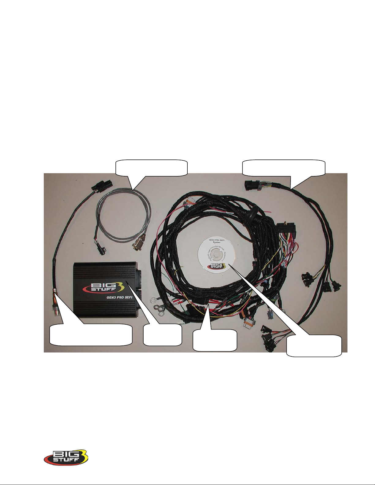
The BigStuff Engine Management System includes the following components:
• Black, powder coated aluminum Engine Control Unit (ECU)
• Main Wire Harness
• Injector Harness
• Wide-band Oxygen Sensor (handle with care!)
• Communication Cable
• CD ROM with BigComm user interface software and Instruction Manual
Communications Cable
Injector Wire Harness
Sensor
ECU
Harness
Software CD
Version 1.0 5
Page 7
BigStuff3 Pro SEFI System (LS1)
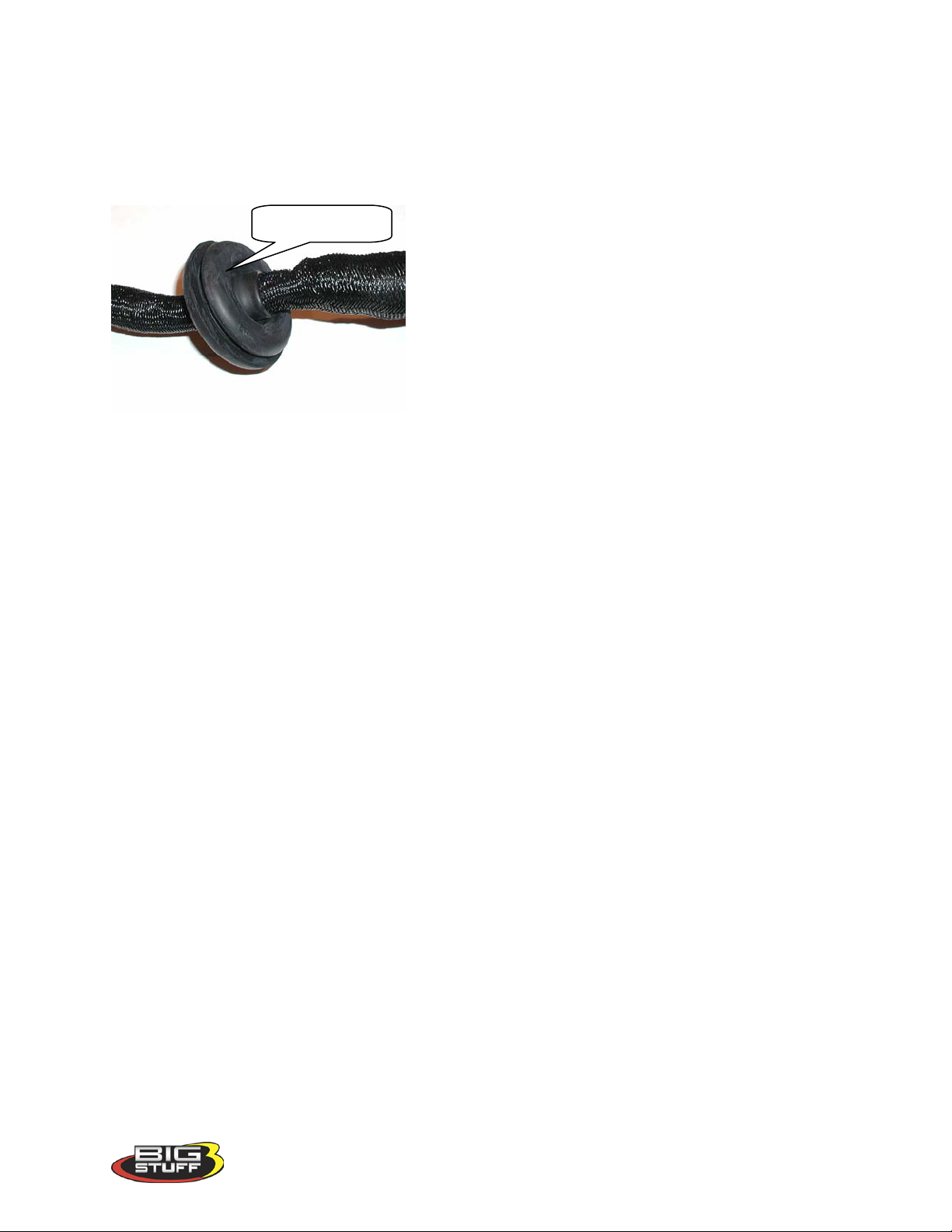
Firewall grommet
4. Main Wire Harness Installation
To improve the overall wire harness installation process, the harness was manufactured with
identification labels at the end of each wire or connector to ensure that connections are
terminated correctly. The main wire harness has two halves; one half is intended to be located
inside the vehicle, with the ECU, the other half connects to the sensors in the engine
compartment. The two halves of the harness are
separated by a firewall grommet (see photo) designed to
fit snuggly in a 2-1/8” hole, which needs to be located
in the firewall.
The best location for the firewall hole is in an
unobstructed location, on either side of the engine
closest to where the ECU will be mounted in the
passenger compartment. Care should be taken to keep
the harness as close to the center of the vehicle as
possible. Locating the hole to far away from the vehicle center may affect wire lengths, which
need to connect to sensors on the engine. Once the main harness is installed the connections
need to be made to sensors, the ECU, etc. The paragraphs below describe how and where each
connection should be made.
The instructions below are specific to the BigStuff engine management systems. Hyperlinks
(underlined, blue wording) in the column titled “Further Details” were included to further assist
with the main wire harness installation. Left clicking the PC’s mouse on the hyperlink will
immediately link to a photo of the connector along with additional installation information. To
return to the same location in the table, simply left click on the “Return-to” hyperlink at the end
of the text.
Note: Additional components such as relays and special connectors may be required to complete
your specific installation. Contact your dealer for further details.
Version 1.0 6
Page 8

BigStuff3 Pro SEFI System (LS1)
Wire
Type
Calport
Black 3-way
The
Connect one end
computer.
The CalPort allows for
2-Step
Single yellow wire
2-Step trigger
function
Clutch or trans
brake switch
Two_Step_Trigger
Tach
Single green Wire
Tachometer
Connects to
tachometer
Tach
HS GM FP
Single lead Packard
striped wire.
High Side
Connect to the
relay.
Do not connect this wire
Fuel_Pump
LS FP
Single lead Packard
Low Side
Connect to the
Do not connect this wire
Fan
Single lead Packard
Engine
Connect to the
Do not connect this wire
Fan
LS1 Crank
Black 3-way
LS1 Crank
Connect to stock
starter motor
LS1_Crank_Sensor
+12V Switch
Single pink wire
Switched 12V
Connect to a 12V
position
See paragraph below
Battery (4
Four (4) 3/8” ring
Positive and
The vehicle
See paragraph below
Harness
Label
Color/Connector
Packard connector
with a purple seal
connector with a
single red and white
Label
Definition
calibration
port that
allows the
ECU to
interface with
an external
computer
drive
Connect To Further Details
of the RS-232
communications
cable (supplied)
to the ECU and
the other end to
the serial port of
an external
communication between
the BigStuff ECU and an
external Personal
Computer (PC) running
the BigComm software.
Click CalPort for further
information.
vehicle
positive side of
the fuel pump
directly to the fuel pump.
A relay must be used.
connections)
connector with a
single black wire.
drive Ford
negative side of
the fuel pump
directly to the fuel pump.
A relay must be used.
relay.
connector with a
single red wire.
cooling fan
connection
negative side of a
cooling fan relay.
directly to the fan or
positive side of the relay.
A relay must be used.
Packard connector
with a purple seal
terminals. Two (2)
red wire terminals
and two (2) black
wire terminals.
shaft
connection
supply input
Negative
Battery
Connections
LS1 crank shaft
sensor located by
source that is
“live” when the
ignition key is in
the “crank”
battery only!
titled “Ignition
Connection” for further
relevant information.
Switched_Ignition
titled “Battery
Connections” for further
relevant information.
Battery_Connections
Version 1.0 7
Page 9

BigStuff3 Pro SEFI System (LS1)
Wire
Type
Boost
Black 4-way
Staged or
Connects to
boost valve
Boost
LS1 Cam
Black, 3-way
Camshaft
Connect to the
engine block
Cam
H2O
Black, 2-way
seal.
Engine
Input
Connect to the
Coolant_Temp
Air
Gray, 2-way
Engine Intake
Connect to the air
the throttle body
Air_Temp
IAC
Black, 4-way
seal.
Idle Air Speed
Connect to the
the throttle body.
Meters and controls
during cold starts. IAC
TPS
Black, 3-way
Throttle
The TPS located
Senses the position of the
TPS
MAP
Black, 3-way
Manifold
Connect to the
manifold
MAP
Injector
Black, 10-way
Injector
Connect to main
Injector_Harness
LS1 Coils
Ignition coil
LS1_Odd_and_Even_Coi
Harness
Label
Color/Connector
connector with an
orange seal
Packard connector
with a purple seal
Packard connector
with a light blue
Packard connector
with a light blue
seal.
Label
Definition
PWM Boost
Control
Position
Sensor Input
Cooling Fluid
Temperature
Air
Temperature
Input
Connect To Further Details
optional 4-way
connector to
solenoid or PWM
stock LS1
camshaft position
sensor located on
the back of the
stock LS1 coolant
temp. sensor.
temp. sensor
typically located
in the air intake
duct between the
air cleaner and
Even & Odd
Packard connector
with a light blue
Packard connector
with a purple seal.
Packard connector
Packard connector
Control (IAC)
input
Position
Sensor
Absolute
Pressure
Sensor
harness
IAC motor assy.
located on or near
at the end of the
throttle shaft on
the throttle body
stock MAP sensor
located on the
back of the
wire harness
intake air around the
throttle blades at idle and
throttle blades [0%
(throttle closed) to 100%
(throttle wide open).
connector
Light gray 7-way
Packard connectors
with an orange
seals
Even (2-4-6-
8) & Odd (13-5-7)
cylinder bank
coils
connector on the
Even (2-4-6-8)
and Odd (1-3-5-7)
cylinder banks.
l_Connections
Version 1.0 8
Page 10
BigStuff3 Pro SEFI System (LS1)
Wire
Type
LS1 Coils
Ground cable
packs
Engine block or
ground location
LS1_Odd_and_Even_Coi
Wide Band
Black 6-way
N/A
Connects to the
See photo and further
Main Fuse &
Relay
Main_Fuse_and_Relay
Vehicle
Battery Fuse
Vehicle_Battery_Fuse
Header
No label, see
Column
BigStuff Engine
Header_Connector
3-way, black
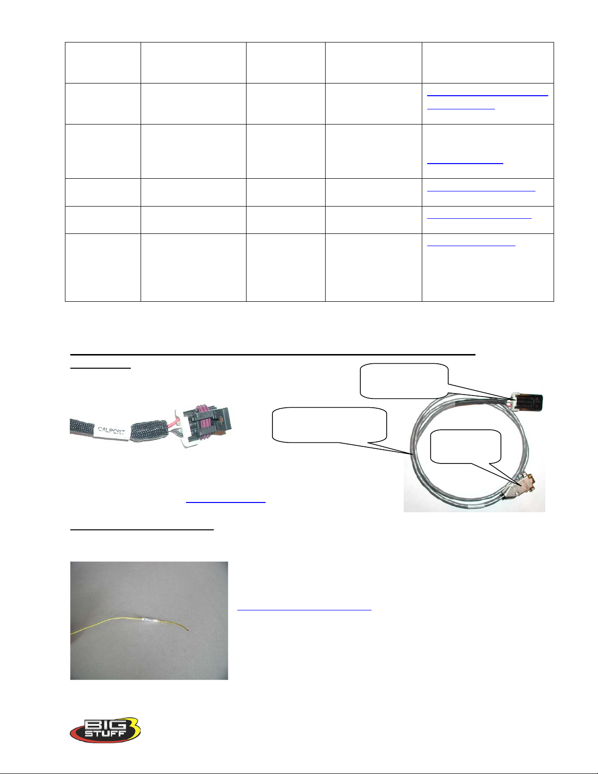
Communications Cable
Harness
Label
Ground
O2
Connector
The paragraphs below further support the information outlined in the table above.
Calport [(software calibration cable interface connector) – (3-way Black Packard Connector)]
Do not connect the communications cable until all the hardware and
software is installed. See the BigComm Users Instruction Manual
for further information.
2-Step Trigger (Yellow wire)
Connect this wire to the clutch or trans brake switch. If 12Volts are applied to this wire and the
Color/Connector
Black 3/8 ring
terminal
connector with gray
locking mechanism
Label
Definition
for LS1 Coil
Connect To Further Details
equally adequate
Wide band O2
sensor.
l_Connections
details.
Wide_Band_O2
N/A N/A N/A
N/A N/A N/A
N/A
link to photo
in “Further
Control Unit
(ECU)
Details”
Packard connector
(supplied)
AMP RS-232
connector
Back_to_Calport
2-Step RPM criteria are met the ECU will maintain the
engine RPM to the 2-Step limit. For more information on
configuring the 2-Step function go to
Back_to_Two_Step_Trigger
Version 1.0 9
Page 11
BigStuff3 Pro SEFI System (LS1)
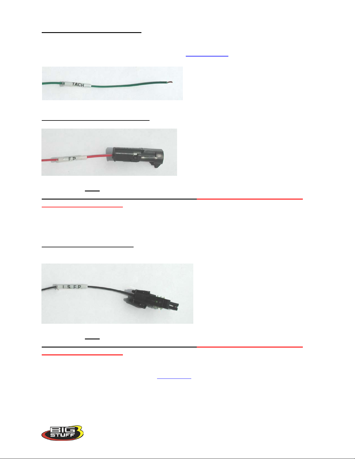
Tach (Tachometer) – Green Wire
This wire supplies a generic Tach “out” signal and will drive most traditional tachometers. A 4pulse per revolution, for a V8 engine, is outputted. Back_To_Tach
High Side (HS) GM Fuel Pump (FP) – (Single lead Packard connector with a single red and
white striped wire)
This connector must go to the positive side of a fuel pump relay, not directly to the fuel pump.
Terminating this connection directly to a fuel pump will damage the Big Stuff controller
and will void the warranty! The fan connector is identical to the fuel pump connector(s); so
make sure the wire label is read to ensure the connector is terminated correctly. The fuel pump
relay and wiring provisions are not supplied with the system. Contact your BigStuff system
dealers for a relay and/or further details.
Low Side (LS) Fuel Pump (FP) – (Single lead Packard connector with a single black wire)
This connector must go to the negative side of a fuel pump relay, not directly to the fuel pump.
Terminating this connection directly to a fuel pump will damage the Big Stuff controller
and will void the warranty! The fan connector is identical to the fuel pump connector(s); so
make sure the wire label is read to ensure the connector is terminated correctly. The fuel pump
relay and wiring provisions are not supplied with the system. Contact your BigStuff system
dealers for a relay and/or further details. Back_to_FP
Version 1.0 10
Page 12
BigStuff3 Pro SEFI System (LS1)
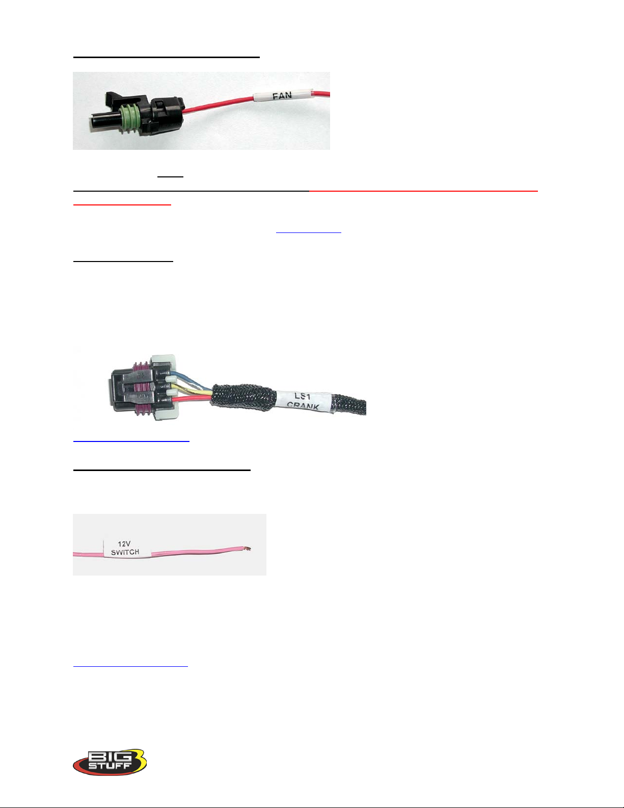
Fan Control (engine cooling fan) – (Single lead Packard connector with a single red wire)
This termination must go to the negative side of a fan relay, not directly to the fan.
Terminating this connection directly to a fan will damage the BigStuff controller and will
void the warranty! The fan connector is identical to the fuel pump connectors; so make sure
the label is read to ensure the connector is terminated correctly. Contact your BigStuff system
dealers for a relay and/or further details. Back_to_Fan
LS1 Crank Sensor (Black 3-way Packard Connector)
Connect to stock LS1 crank sensor, located on the passenger side of the engine, by the starter
motor.
Note: The LS1 Cam, Crank and MAP sensors use the same 3-way Packard connector,
therefore be sure to connect each of the 3-way connectors to the appropriate sensor!!
Back_to_Crank_Sensor
12V Switched – (Sing le pink wire)
A secure connection must be made to a switched 12V supply. The best and in most cases the
only source of a switched 12V supply is at the vehicle fuse block. The ECU must have a “live”
12V supply during cranking. If the 12V supply does
not stay live, during cranking, the ECU will not
function. A simple way to determine if a live 12V
supply exists during cranking is to check it with an
inexpensive voltmeter. Securely fasten the voltmeter’s
red (+ positive) wire to the ignition input on the fuse block. Secure the voltmeter’s black wire (negative) to a ground location on the fuse block or another adequate location. Once the
voltmeter connections are made, crank the engine. The voltage meter should indicate an output
voltage of between 8V to 14 volts. If the output voltage is below 8 volts, check to make sure the
battery is fully charged and all the cells of the battery are functioning properly.
Back_to_Switched_Ign
Version 1.0 11
Page 13
BigStuff3 Pro SEFI System (LS1)
Connector Pin Out ID
A Signal
B
Ground
C
Switched Ignition
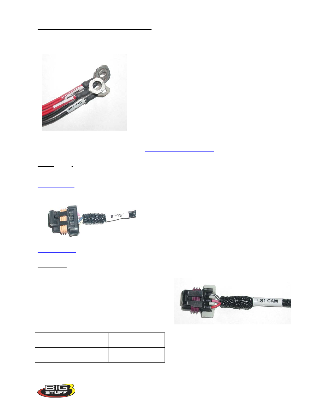
Positive and Negative Battery Connections – (Four (4) 3/8” ring terminals. Two (2) red
wire terminals and two (2) black wire terminals)
THE MAIN WIRE HARNESS BATTERY CONNECTIONS NEED TO BE MADE TO
THE POSITIVE AND NEGATIVE POSTS OF THE
VEHICLE BATTERY TO ENSURE
TROUBLE FREE OPERATION! The positive and
negative battery cable lengths have been designed (are long
enough) to accommodate a trunk-mounted battery. Make
sure the two clearly marked black wires battery (-) are
securely fastened to the negative battery post (NO
EXCEPTIONS). The red cable battery (+) must be
securely fastened to the positive (+) battery post.
Making battery connections to locations on the vehicle other than the battery itself can cause the
ECU to function improperly (potential ground loop issues). Connect these wires to the battery
only after all other connections are made. Back_to_Batt_Connections
Boost (Black 4-way Packard Connector)
Connects to the solenoid(s) valve or PWM boost valve using the provided 4-way connector. See
Boost_Control in Section 60.
Back_to_Boost
LS1 CAM (Black 3-way Packard Connector)
Connect to stock LS1 cam sensor at the back of the
block.
Note: The LS1 Cam, Crank and MAP sensors
use the same 3-way Packard connector,
therefore be sure to connect each of the 3-way
connectors to the appropriate sensor!!
Back_to_Cam
Version 1.0 12
Page 14
BigStuff3 Pro SEFI System (LS1)
LS1 In-line, 1-by-4, IAC
Connector Pin-out
Late Model 2-by-2 IAC
Connector Pin-out
D
A-Hi A C
A-Lo B B
B-Hi C A
B-Lo
D
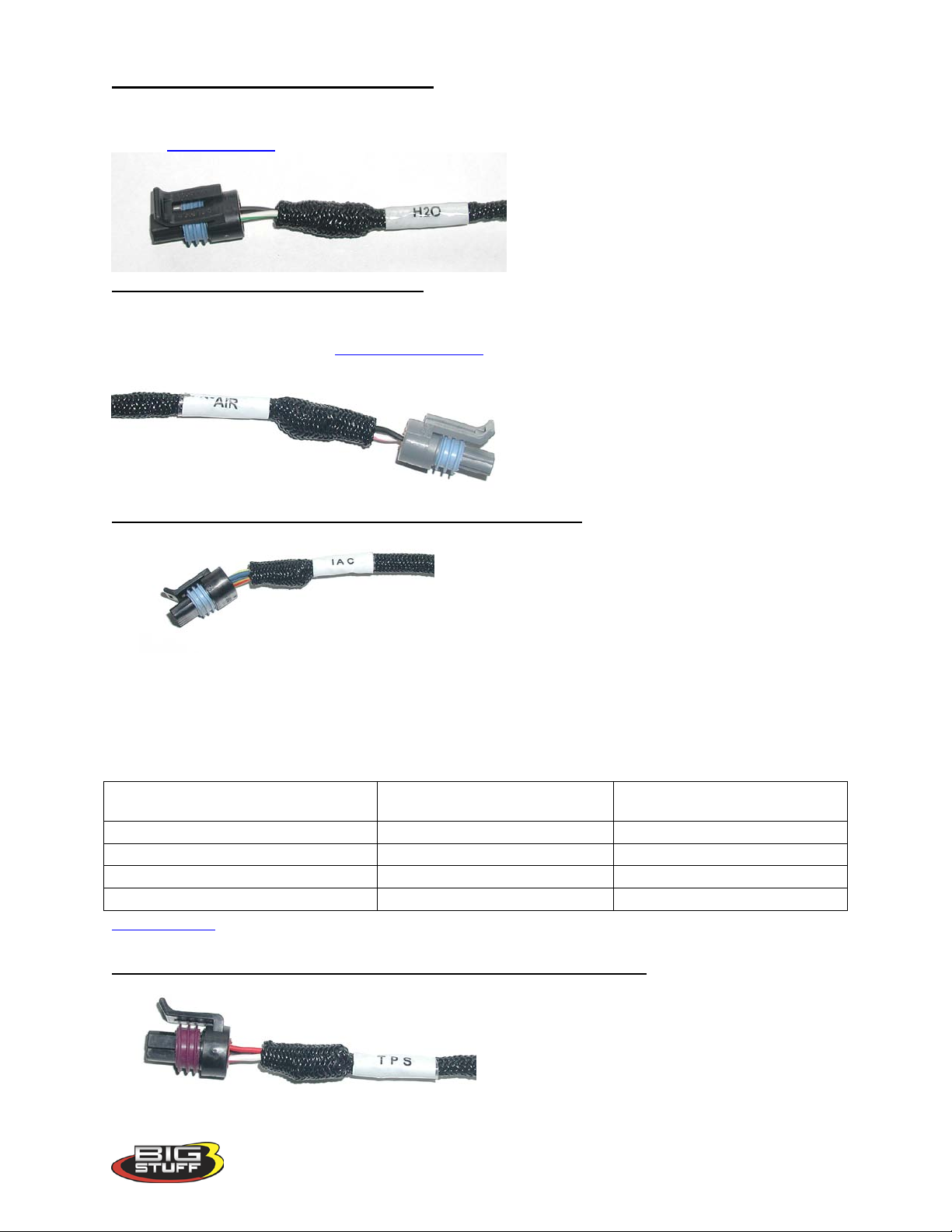
H20 – (Black, 2-way Packard connector)
This connector mates with a GM style coolant temperature sensor (front driver’s side cylinder
head). Back_to_H2O
Air – (Gray, 2-way Packard connector)
This connector mates with a GM style air temperature sensor in the inlet duct between the air
cleaner and the throttle body. Back_to_Air_Temp
IAC (Idle/Air Control) – (Black, 4-way Packard connector)
The main harness IAC connector was designed to work with a GM style IAC motor and valve
assembly with an in-line 1-by-4 connector.
Alternatively, the factory installed 1-by-4 in-line connector can be removed and replaced with a
2-by-2 connector per the pin-out table below.
Back_to_IAC
TPS (Throttle Position Sensor) – (Black, 3-way Packard connector)
late model GM or Ford TPS connector per the pin-out tables below.
IAC Coils
Connect the TPS connector to the LS1 throttle
position sensor, located on the engine throttle
body.
Alternatively, the factory installed TPS
connector can be removed and replaced with a
Version 1.0 13
Page 15
BigStuff3 Pro SEFI System (LS1)
Late Model GM or Ford TPS Connector
Pin-Out
A
5 Volt Reference C B
Ground A C
Signal
B
Standard GM 1-by-3 MAP
Connector Pin-Out
A
5 Volt Supply C B
Signal B C
Ground
A
LS1 TPS Connector Pin-Out Goes To
Back_to_TPS
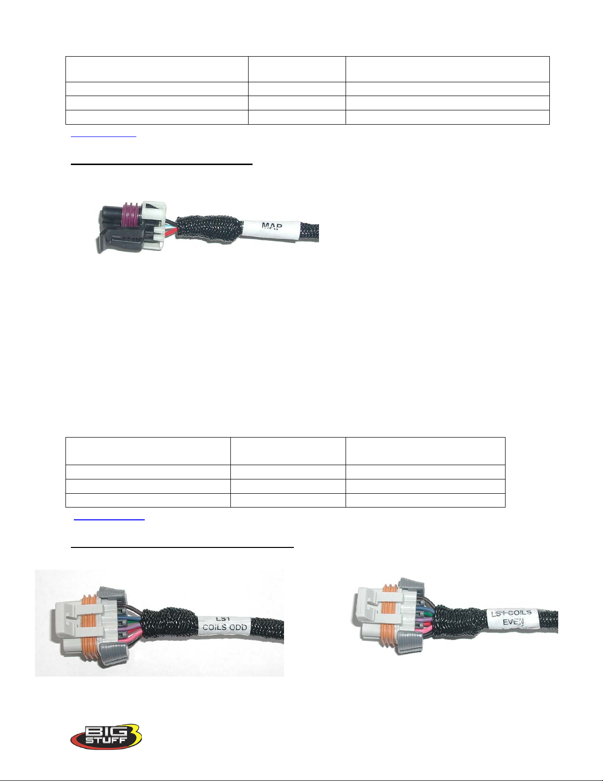
MAP (Manifold Absolute Pressure) – (Black 3-way Packard connector)
Connect to a LS1 style (0 to 1 BAR)
Manifold Absolute Pressure (MAP) sensor
located at the back of the manifold. For
normally aspirated engines, a 1 bar sensor
is used. For blown or turbocharged
applications a 2 BAR MAP sensor must be
used for boost pressures up to 15 PSI. For
boost pressures up to 30 PSI a 3 BAR MAP sensor must be used. If a 2 or 3 BAR MAP sensor is
used, the harness side MAP sensor connector must be replaced. Contact a BigStuff dealer if
questions come up related to the MAP sensor supplied with your system and to procure the
necessary connectors.
For speed/density applications the MAP sensor must be connected to an intake manifold port.
For Alpha/N systems use the sensor to sense ambient air pressure in the hood scoop or air
cleaner.
Note: The LS1 Cam, Crank and MAP sensors use the same 3-way Packard connector,
therefore be sure to connect each of the 3-way connectors to the appropriate sensor!!
LS1 MAP Connector Pin-Out Goes to
Back_to_MAP
LS1 Odd & Even Coil-On-Plug Connections [Two (2) Gray 7-way Packard Connectors]
Version 1.0 14
Page 16
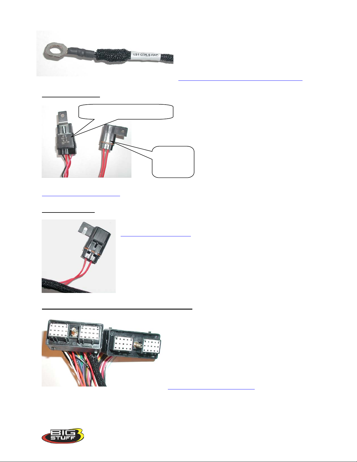
Connect the LS1 Coils Odd connector to the
WBO2 &
WBO2 & Coil V-Batt Relay
ignition coil pack connector on the odd fire (13-5-7) bank of the engine. Do the same for the
even fire (2-4-6-8- ) bank of the engine.
Securely fasten the LS1 Coils GND cable to the
engine block or cylinder head!
Back_to_Even_and_Odd_Coil_Connections
Main Fuse & Relay
Coil V-Batt
30 Amp fuse
Back_to_Main_Fuse_Relay
ECU 3-Amp Fuse
This fuse protects the ECU electronics.
Back_to_Veh_Batt_Fuse
Two (2) Thirty (30)-Way ECU Header Connectors
Connect the main wire harness header connectors to
the BigStuff ECU. The two 30-way MWH header
connectors are keyed such that they will only fit in
one of the two ECU mating-half connectors. To
fasten the MWH connectors to the ECU, use a 1/4nut driver. Connect the head connectors only after
the battery connections are made. Connect header
connector A through K first, the L through Y.
Return_to_Header_Connectors
BigStuff3 Pro SEFI System (LS1)
Version 1.0 15
Page 17
BigStuff3 Pro SEFI System (LS1)
Main Wire Harness side
This connecto r mates with
O2 connector
Injector harness to
connector (female)
LS1 main wire harne s s to
Injector connector cylinder
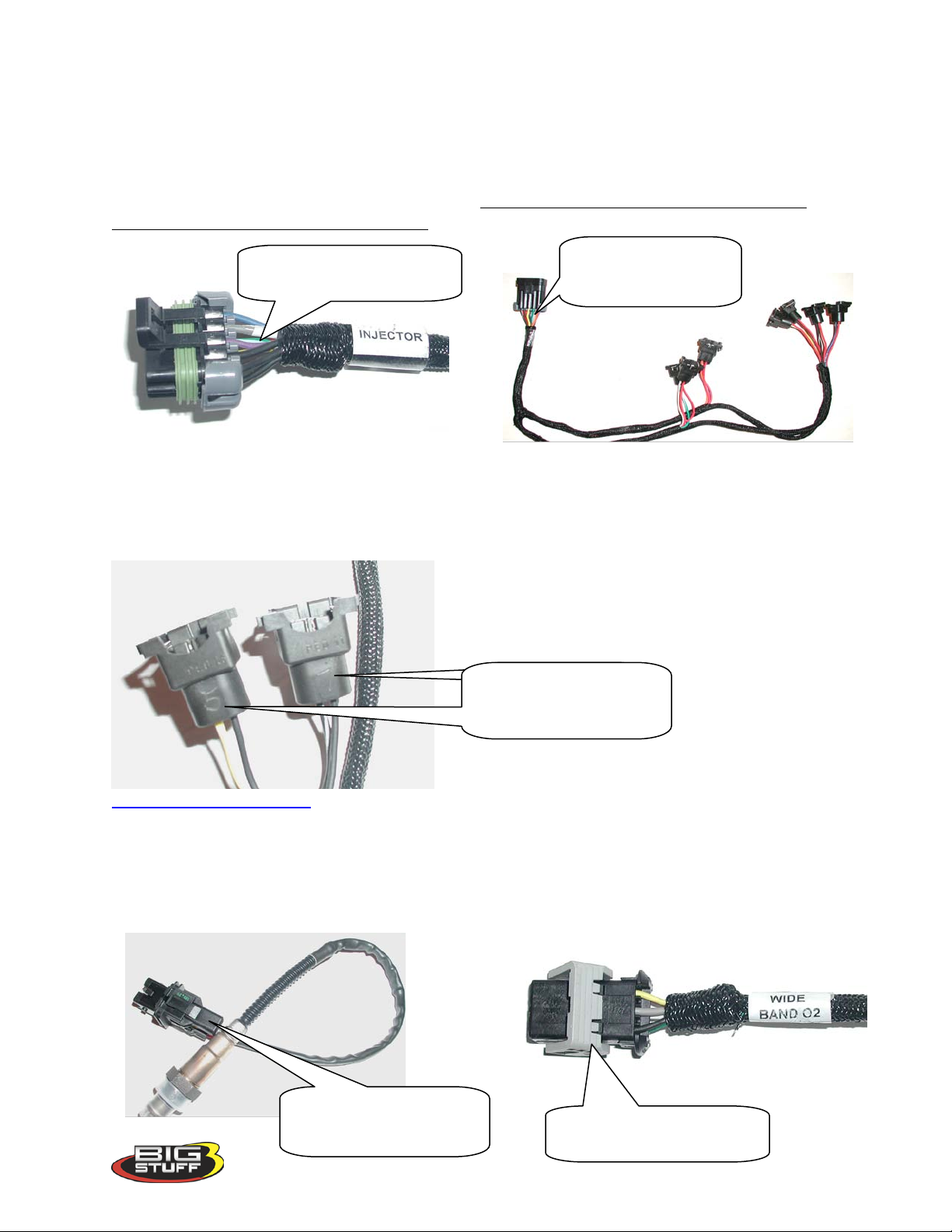
5. Injector Harness Installation – [Black, 10-way Packard Connectors (Male & Female)]
Once the main harness is installed and all the connections to it are made, the injector harness can
be installed and connected to the main harness. The standard injector harness is configured to
work with an LS1firing order (1-8-7-2-6-5-4-3). The LS1 injector harness 10-way connector
should be located at the rear of the engine.
injector harness connector
The injector harness is constructed with the main
harness connector located half way between the
two banks of fuel injector connectors. The cylinder number is engraved into the injector harness
connector from the factory. Connect the individual injector connectors to each fuel injector.
Lastly, connect the injector harness to the main wire harness.
main harness
engraving s (cylinders5 & 7
shown)
Back_to_Injector_Harness
6. Wide Band Oxygen Sensor Installation
Once the main and injector harnesses are installed, the Wide Band Oxygen (WBO2) sensor
needs to be installed and connected to the main harness. First, install the wide band sensor.
Main Harness Wide Band
connector for O2 Sensor.
Version 1.0 16
Page 18
BigStuff3 Pro SEFI System (LS1)
10o angle, minimu m
Oxygen Sensor
Oxygen sensor mounting
needs to be welded)
Exhaust Pip e
The optimal
This side (with the mounting lip) goes into the
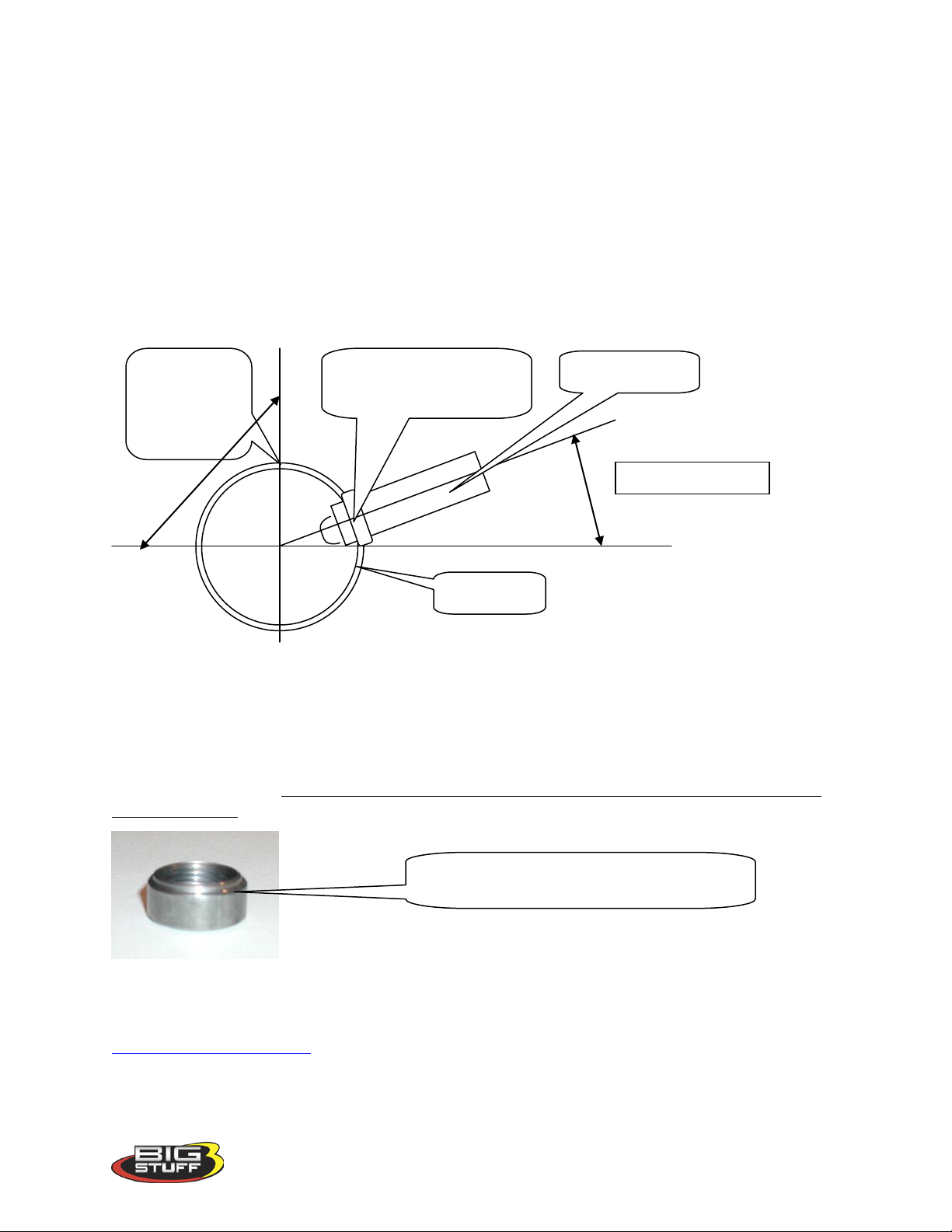
The WBO2 sensor threads into the sensor mounting bung [(optional) (see picture below)], which
needs to be drilled and welded into the exhaust pipe. Before drilling and welding read the design
guidelines below.
• Install mounting bung approximately 8” – 12” from where the primary pipes enter the
exhaust collector.
• Make sure the mounting location selected does not allow condensation to collect directly
in front of the sensor. Make sure there are no depressions, projections, edges, etc. in the
exhaust pipe near the sensor tip.
• The mounting angle of the sensor should be tilted a minimum of 10o to the horizontal tip
of the sensor. The tip of the sensor must be tilted down. See the diagram below. The
optimum sensor angle is 90
o
.
angle is
completely
vertical or 90
o
bung (entire circumference
• Make sure sensor cabling is routed and secured away from the exhaust system.
Stainless steel mounting bungs are also available for turbocharged applications.
Drill a 7/8” – 15/16” hole in the exhaust pipe. Weld a WBO2 sensor-mounting bung into the
exhaust pipe. The mounting bung was manufactured with a lip to help locate it prior to welding
it to the exhaust pipe. The entire circumference of the mounting bung must be welded and free
of exhaust leaks! Contact your BigStuff3 dealer to procure a mounting bung.
exhaust pipe to locate it prior to being welded
Once the sensor-mounting bung is welded into place, thread the sensor
into the bung. Installation torque is about 10 – 15 ft/lbs. Connect the oxygen sensor 6-way
connector (with gold plated terminals) to the main wire harness.
Back_To_Wide_Band_O2
Version 1.0 17
Page 19
BigStuff3 Pro SEFI System (LS1)
7. ECU Installation
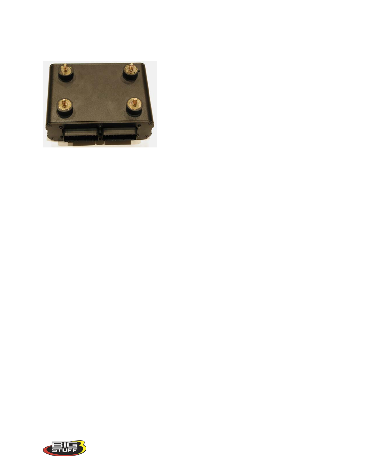
The ECU must be installed in the passenger
compartment! The ECU has four ¼-20 x ½” threaded
isolation grommets threaded into the bottom of the
housing. Once installed, connect the two (2) 30-way
main wire harness header connectors to the ECU.
Note: If the factory installed isolation grommets are
not used to mount the ECU, threads into the housing
cannot extend beyond the ¼” factory installed depth.
Using bolts or threaded rods that are longer than ¼”
will damage the ECU and void the warranty!
The GEN3 system hardware installation process in now complete. The next step is to install the
BigComm software, which allows the sensor interfaces to be checked, and ultimately start and
operate the engine.
The remainder of the manual will describe how to install and use the BigComm software to
monitor and calibrate the GEN3 ECU parameters and variables.
8. BigComm Software Overview
The GEN3 system can be configured to operate on almost any engine configuration, normally
aspirated, supercharged and turbocharged applications! The BigComm software was designed to
act as the interface between the BigStuff3 GEN3 ECU and the engine it is installed on. View it
as the screwdrivers and wrenches once used to make crude adjustments to a carburetor. The
BigComm software allows the user extraordinary fuel and ignition system tune ability for
improved performance and drivability.
The BigComm software allows full user access to all of the tables needed to calibrate the GEN3
system. Calibrations can be modified both “on-line” and “off-line”.
The engine control tables in the BigComm ECU are stored in non-volatile memory, allowing for
the stored information not to be lost when power to the ECU is removed.
The minimum computer requirements to run the BigComm software are:
• Microsoft Windows 95/98/Me/2000/ NT or XP
• 300 MHz or faster Pentium processor.
• BigStuff3 recommends a minimum of 128K of RAM.
• RS-232 serial port recommended. A USB port can also be used with a port adapter (not
included).
• CD ROM disc drive.
Version 1.0 18
Page 20
BigStuff3 Pro SEFI System (LS1)
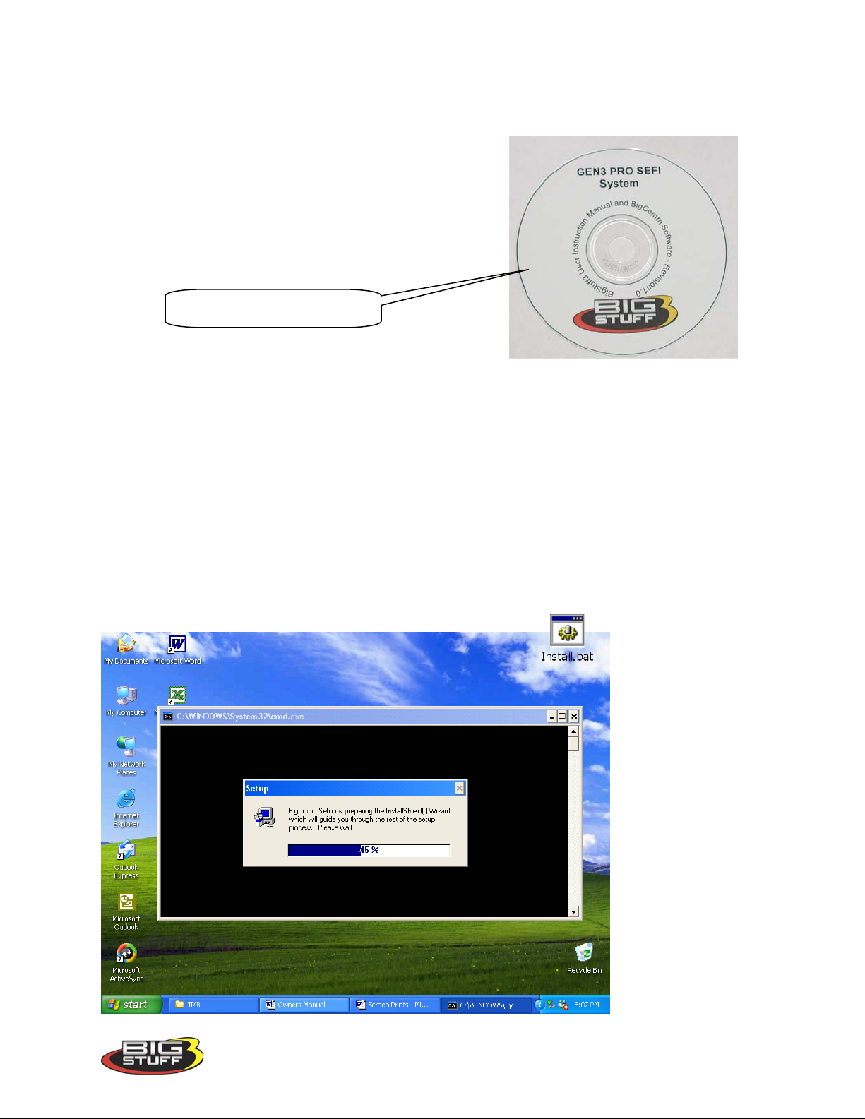
BigComm software CD ROM.
Engine calibrations are best performed on a dynamometer. If the user elects to calibrate the
engine in the vehicle, BigStuff3 strongly recommends that two people are involved, one person
to drive the vehicle, the other operate the laptop computer.
9. BigComm Software Installation
The GEN3 system is supplied with a CD ROM software
Disc and a 5’communication cable, which connects the
BigStuff3 ECU with a personal computer (PC). A 25’
cable is also available. Contact your dealer for further
details.
To install the software, take the “BigComm Install” CD
ROM out of its protective cover. Open the PC’s CD
ROM drive and insert the BigComm CD ROM disc into the disc drive drawer. Close the disc
drawer and the BigComm software will automatically invoke the install process. The following
screens will be displayed. Follow the installation steps shown below.
If the CD Auto Run function on your computer does not automatically start. To install the
software, take the “BigComm Install” CD ROM out of its protective cover. Open the PC’s CD
ROM drive and insert the BigComm CD ROM disc into the disc drive drawer. Close the disc
drawer and the BigComm software will automatically invoke the install process.
If the CD Auto Run function on your computer does not automatically start, go the computer
drive that the BigComm CD is installed in and double click on the drive, e.g. “D”. Once the CD
ROM opens, double click on the folder named “Install.bat”
Version 1.0 19
Page 21
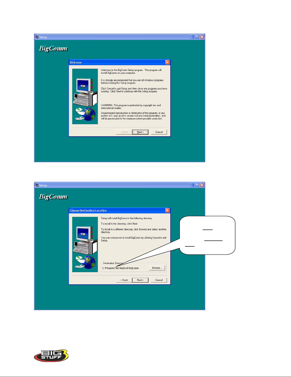
The following screen will automatically open.
The BigComm
BigStuff3 Pro SEFI System (LS1)
Click the left mouse button on Next>. The following screen will open.
software must to be
installed in the
Windows Program
Files Directory!
The BigStuff3, BigComm software must be installed in the Window’s “Pr ogram Fil e s ” folder
as shown above. Click the left mouse button on Next>. The following screen will open.
Version 1.0 20
Page 22
BigStuff3 Pro SEFI System (LS1)
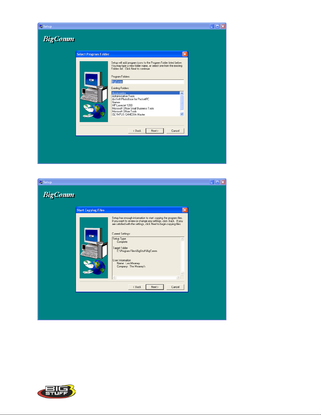
Click the left mouse button on Next>. The following screen will open.
Click the left mouse button on Next>. The following screen will open.
Version 1.0 21
Page 23
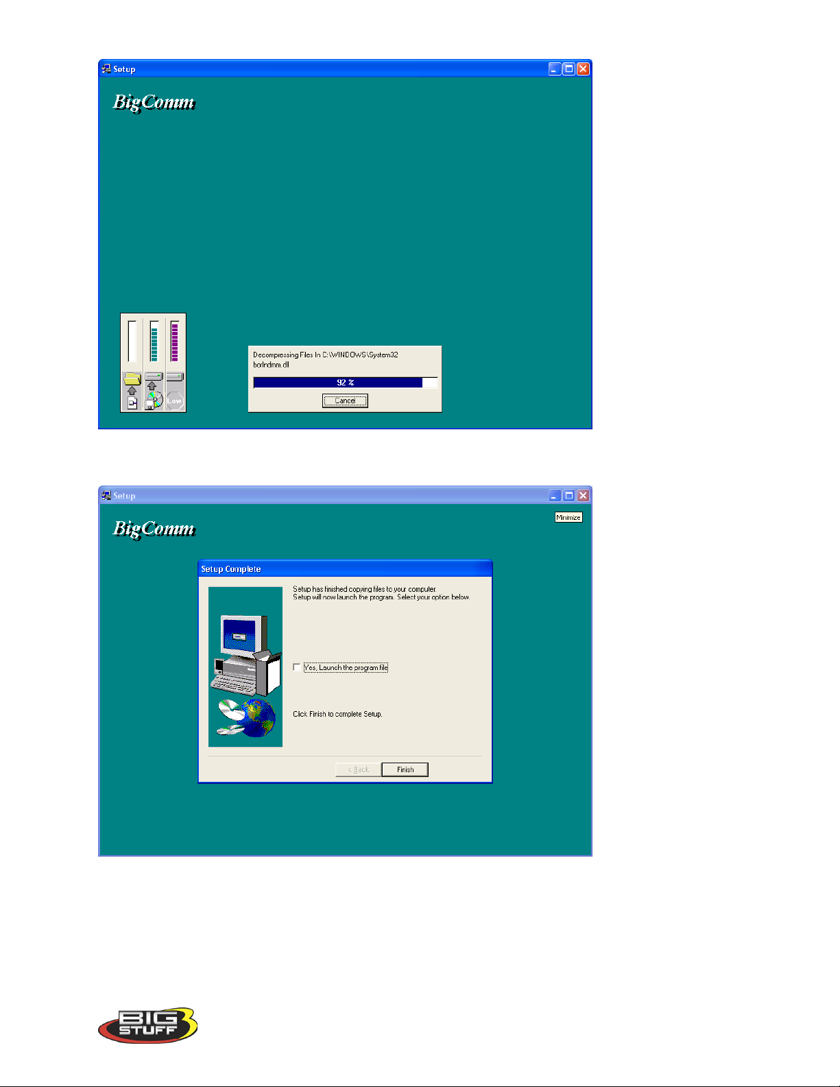
Once 100% is reached, the following screen will open.
BigStuff3 Pro SEFI System (LS1)
To launch the BigComm software, check the box titled “Yes, Launch the program file.”
Otherwise, click the left mouse button on “Finish.”
The BigComm software has now been successfully installed on your personal computer! The
following screen will open automatically. This screen provides the option to drag the BigComm
shortcut icon to the Windows desktop. Minimize all open windows until the Windows desktop
Version 1.0 22
Page 24
BigStuff3 Pro SEFI System (LS1)
BigComm
Packard connector –
AMP RS-232
CALPORT connec tor on
5’ Communication Cable
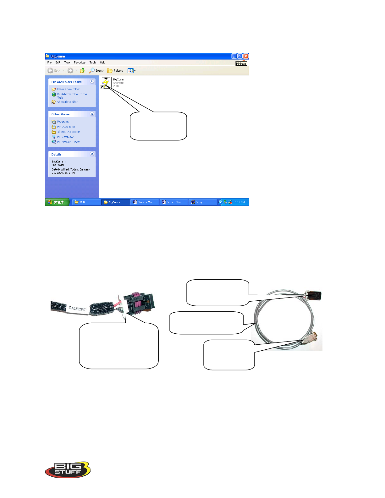
appears. Drag the BigComm shortcut icon onto the desktop. The BigComm icon allows for
quick access to the BigComm software from the Windows desktop.
shortcut icon
10. Communication Cable-to-PC Connection
Using the communication cable supplied with the system, connect the 3-way Packard connector
to the mating half 3-way connector marked CalPort on the Main Wire Harness. Connect the
RS232 connector to the back of the personal computer.
the Main Wire Harness.
Connects to the
Communications cable
Port Problems?
If the RS-232 connector located at the end of the interface cable (supplied with the system)
cannot be connected to your PC, a 9-pin serial port interface adapter will need to be procured. If
the PC is a newer model it will most likely have a USB port. If the PC being used is an older
model it may only have a 25 pin serial port. Make sure the 25-pin port, on the back of the PC, is
a serial port and not a parallel port, there is a difference. The parallel port will not work.
Parallel ports are typically printer ports that let data travel in only one direction. If your PC is
configured with only a USB port, a USB-to-9 pin adapter must be procured. USB-to-9 pin or 25-
Connects to the Main
Wire Harness
(supplied)
connector –
Connects to PC
Version 1.0 23
Page 25
BigStuff3 Pro SEFI System (LS1)
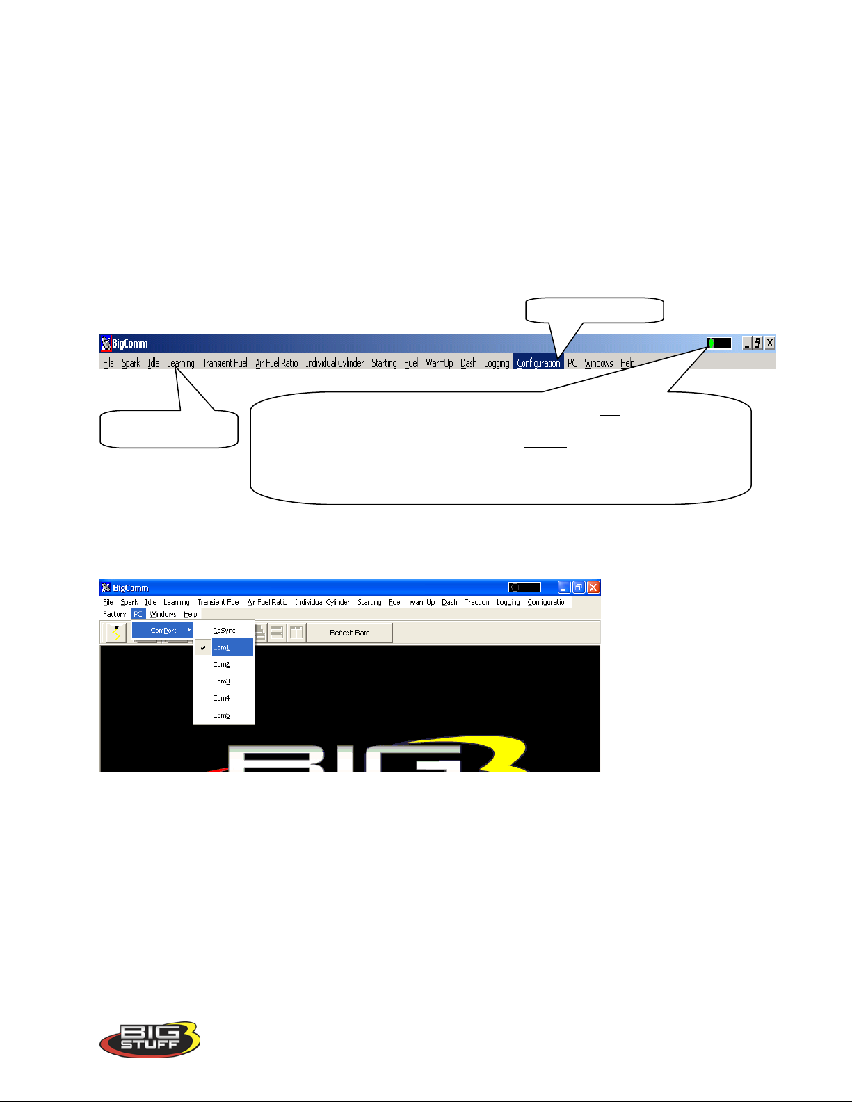
A green sliding ball indicates “On-line” communication has been established
established between t he Big Stuff ECU and an external computer.
BigComm Tool Bar
PC Drop Down
pin-to-9 pin serial adapters are readily available at Radio Shack or comparable stores. Radio
Shack’s USB port to 9-pin serial adapter is part number 26-183 (+/-$40.00).
Prior to establishing communication with the GEN3 ECU, the PC’s COM port, needs to be
selected. In order to complete the PC COM port selection a quick overview of the Tool Bar is
required. The configuration tables within the BigComm software are accessed using the
BigComm Tool Bar explained below.
11. Using the Tool Bar
The Tool Bar is located at the very top of the BigComm Main Menu screen. All of the
BigComm software functionality is accessed using the Tool Bar and associated drop down
screens.
Left mouse click on PC on the main tool bar. Select the COMPort, then COM1. For most PC’s,
COM 1 will be the available port. Close the BigComm software.
between the Big Stuff ECU and an external computer.
A red sliding ball indicates com munication has not
the Big Stuff ECU and an external computer.
A blue sliding ball indicates “Off-line” No communication has been
been established between
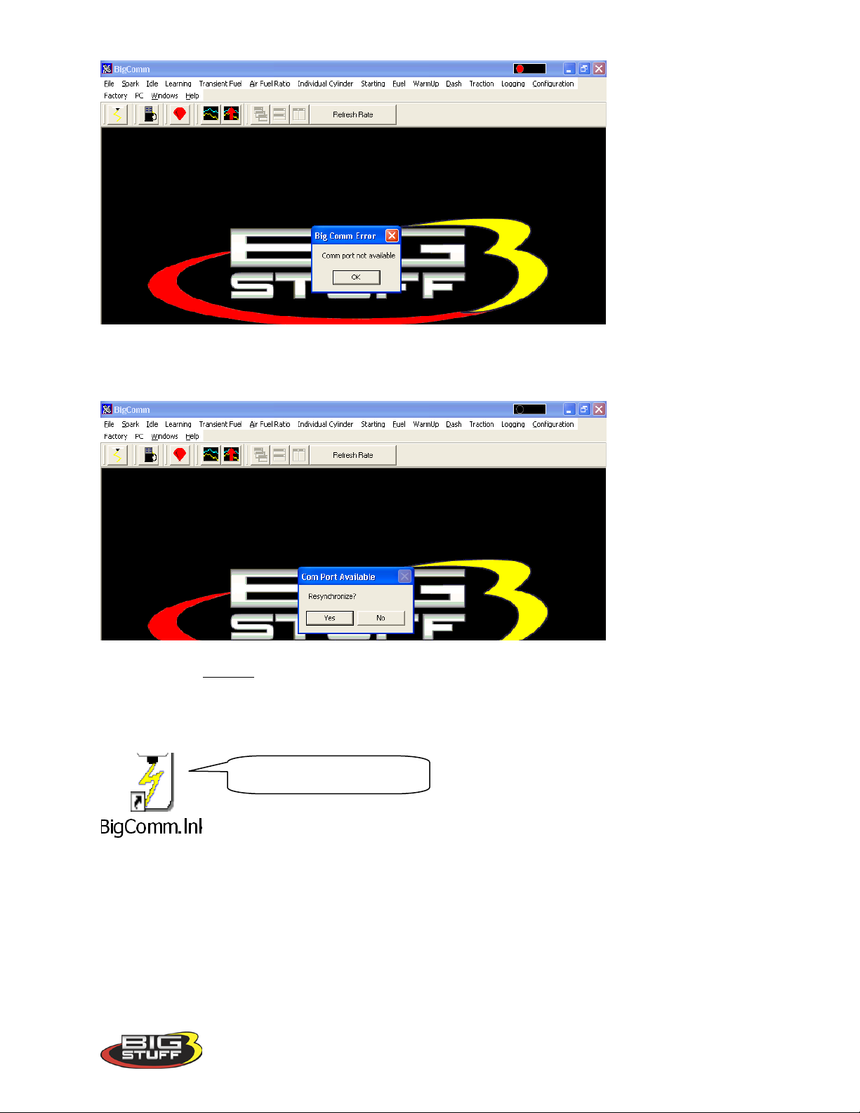
If the Com Port selected is not available, the following message will appear.
Version 1.0 24
Page 26
BigStuff3 Pro SEFI System (LS1)
Select another Com Port until an available port is identified. Once the PC identifies an available Com Port, the following screen will appear.
Press the PC’s “Enter” key or left mouse click on Yes and the Com Port will resynchronize.
Next, double click the left mouse button on the BigComm short cut icon located on the Windows
desktop.
BigComm desktop icon
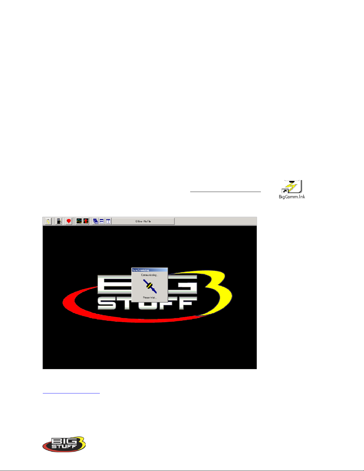
The BigComm software will attempt to establish a connection between the PC and the GEN3
ECU. The following screen will appear.
Version 1.0 25
Page 27
BigStuff3 Pro SEFI System (LS1)
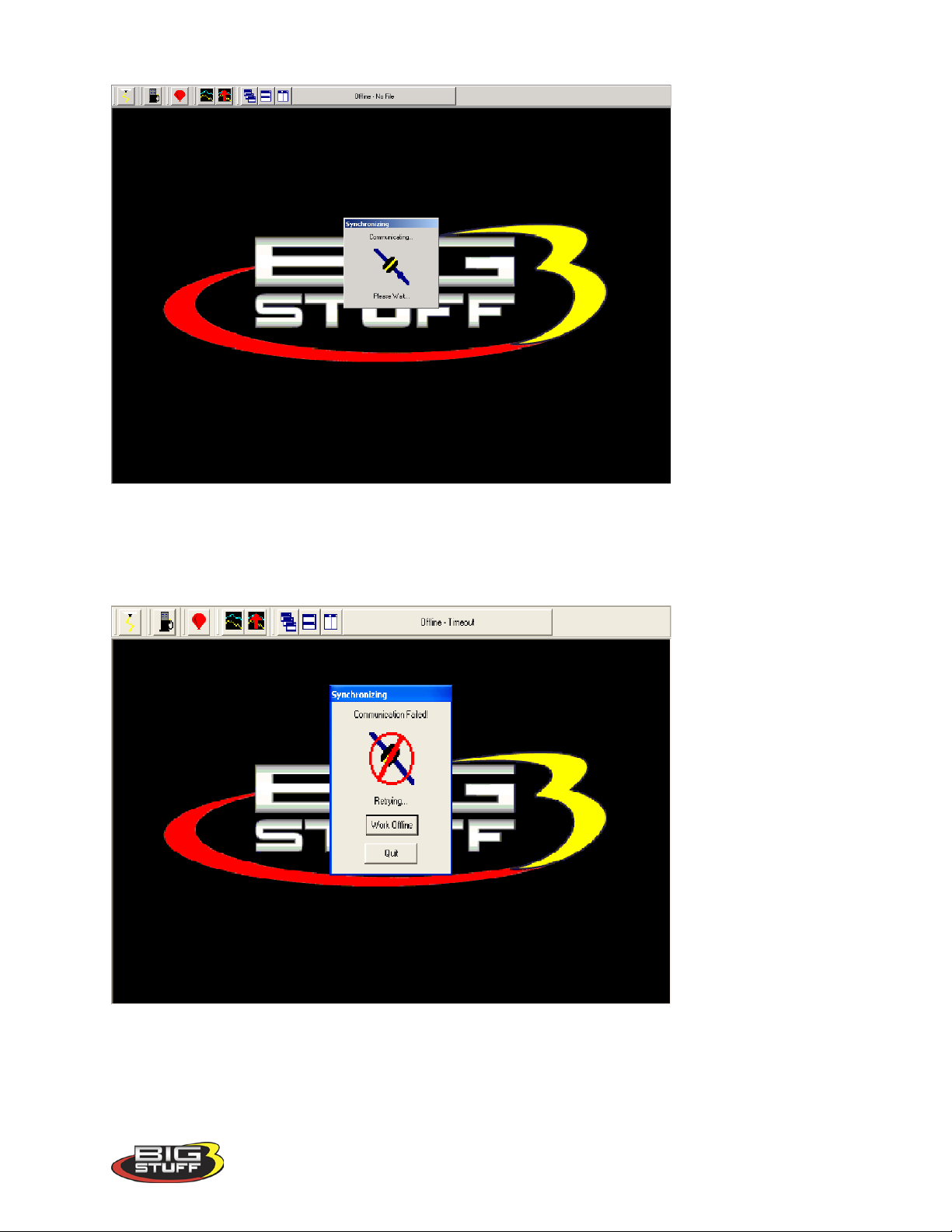
If the GEN3 ECU is not powered up (the ignition key is not in the “Run” position) and the
Communications cable is not connected, communication cannot be established. The following
screen will appear. This may also occur if the Comm Port is not configured correctly. If this
occurs, use the above process of configuring the Comm Port until communication is established.
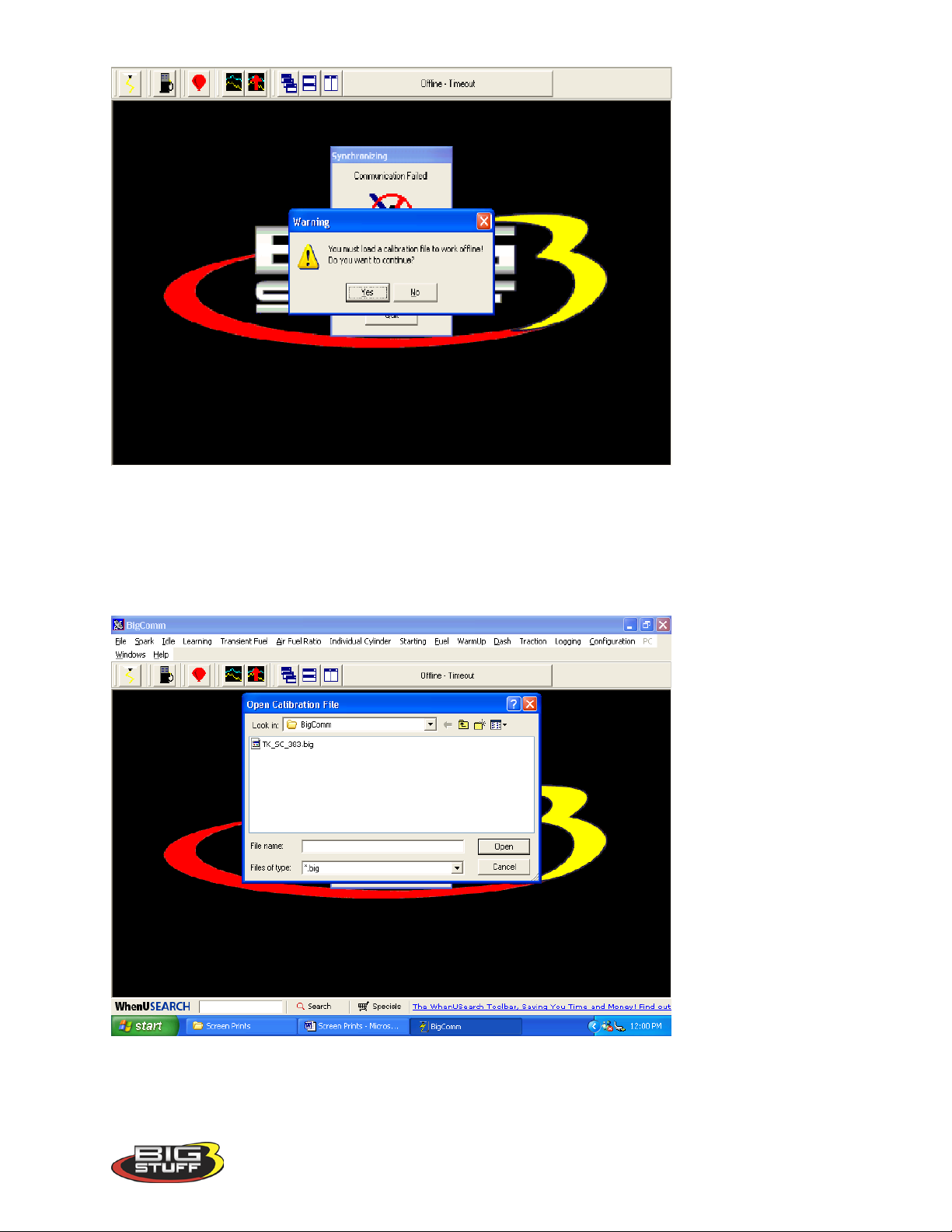
Left mouse click the Work Offline button. The BigComm software will ask what calibration
should be used “off-line”. The following screen will appear, informing the user that a calibration
file must be loaded to work “off-line”.
Version 1.0 26
Page 28
BigStuff3 Pro SEFI System (LS1)
Left mouse click on Yes and the BigComm software should go to the BigComm folder. If the
PC does not automatically take you to the BigComm folder, navigate to C: Program
Files/BigStuff/BigComm. Double left click on the calibration to be used for “off-line”
modifications and the calibration will be loaded. After the calibration is loaded, the Main
BigComm window will open.
Version 1.0 27
Page 29
BigStuff3 Pro SEFI System (LS1)
12. Establishing a Connection
The sequence for connecting the GEN3 ECU to the Main Wire Harness is as follows:
• First connect battery terminals.
• With the ignition switched off, connect the 30-way header connector, with terminals A-K
to the ECU.
• After terminals A-K are connected to the ECU, connect the header connector with
terminals L-Y.
This assembly sequence should preserve the firmware and initial calibration that was loaded in at
the factory.
Assuming that the system wire harnesses, ECU and software are all installed and connected
correctly, the next step is to establish communication between the PC and BigStuff3 GEN3 ECU.
Double check to make sure the communication cable connections, between the PC and to the
GEN3 ECU, are securely in place. Again, the plastic Packard style connector mates with the
main wire harness connector labeled “Calport”. Turn the PC on and power up the BigComm
ECU by turning the vehicle ignition to the “Run” position.
Left mouse click (double click) the BigComm icon on the Windows desktop.
The following screen will appear.
Once communication has been established, the BigComm “Main Menu” screen will open and the
Green_Sliding_Ball in the tool bar will become active.
Version 1.0 28
Page 30

13. BigComm Main Menu Screen
Spark Table
short cut
Fuel Table
short cut
Air/Fuel ratio
Record Log
View logged
data short cut
BigStuff3 Pro SEFI System (LS1)
table short cut
short cut
The engine is not yet ready to be started. A few additional items need to be completed before
attempting to do so!
In most cases, the ECU will be delivered with a calibration that will closely match your engine
configuration. This “base calibration” will allow the engine to be started and run. If this is not
the case, the following steps need to be taken.
Note: BigStuff3 recommends checking all of the settings in the configuration tables to ensure
the system as supplied will operate correctly.
14. Inputting Values into a Cell
There are two methods for inputting values into cells as follows:
• Arrow Keys – Use the PC keyboard arrow keys to navigate the cursor horizontally
and/or vertically to the cell to be changed. Input the desired value and hit “Enter”.
• Using the Mouse - Use the Mouse to navigate the cursor to the cell to be changed and
left Mouse click on the cell. Input the desired value and hit “Enter” to save the change.
15. Closing Windows
Open windows can be closed using the PC’s mouse. To close an open window, left mouse click
on the “X” in the upper right corner of any window. Another method to close open windows,
tables and drop down screens is to hit the PC’s escape key, typically abbreviated as “Esc”. If
multiple windows are open, continue to hit the Esc key until all windows are closed and the main
BigComm window is displayed. Hitting the Esc key too many times may result in a message
stating, “Do you really want to quit?” Hit “No” to continue working with the BigComm
software. Hit “Yes” to close the BigComm software.
Version 1.0 29
Page 31
BigStuff3 Pro SEFI System (LS1)
“Hardware Configuration” dropMain tool bar
To set up, go to
16. Configuration
The BigStuff3 ECU needs to be configured to the engine it will control. For example, the ECU
needs to know if it is operating a 4, 6 or 8 cylinder engine along with other important engine
parameters and variables. The initial configuration steps can be accomplished with the vehicle
ignition key in “run” position and the engine off. The ECU must be supplied with 8V – 14V for
the ECU to be “live”.
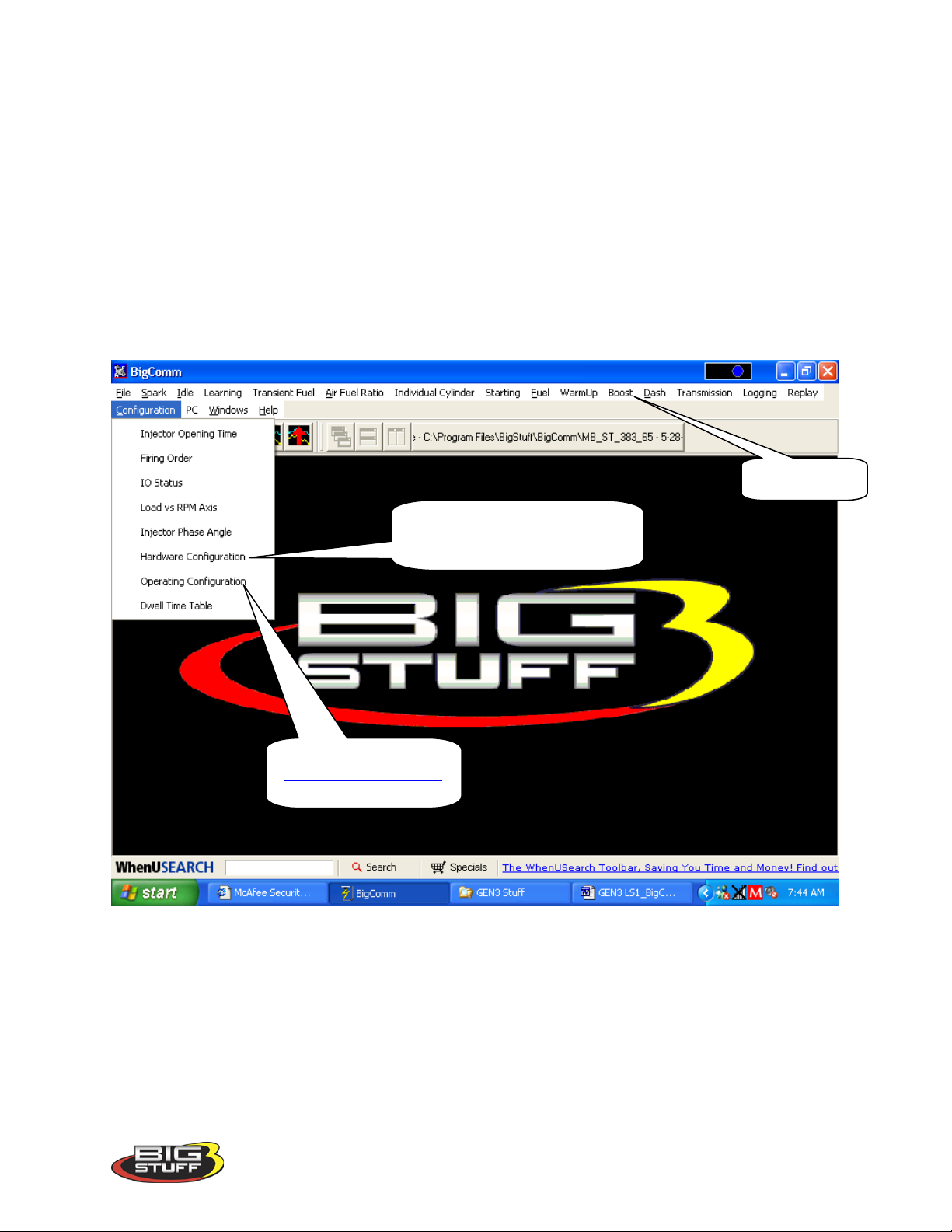
From the tool bar on Main Menu screen, left click on the “Configuration” and the drop down
screen below will open.
17. Hardware Configuration
down. Main_Configuration
OPerating_Configuration
Keep the left mouse button depressed and slide the mouse pointer down until “Hardware Configuration” is highlighted. Release the left mouse button. The screen below will open.
Version 1.0 30
Page 32
Main Configuration Table
BigStuff3 Pro SEFI System (LS1)
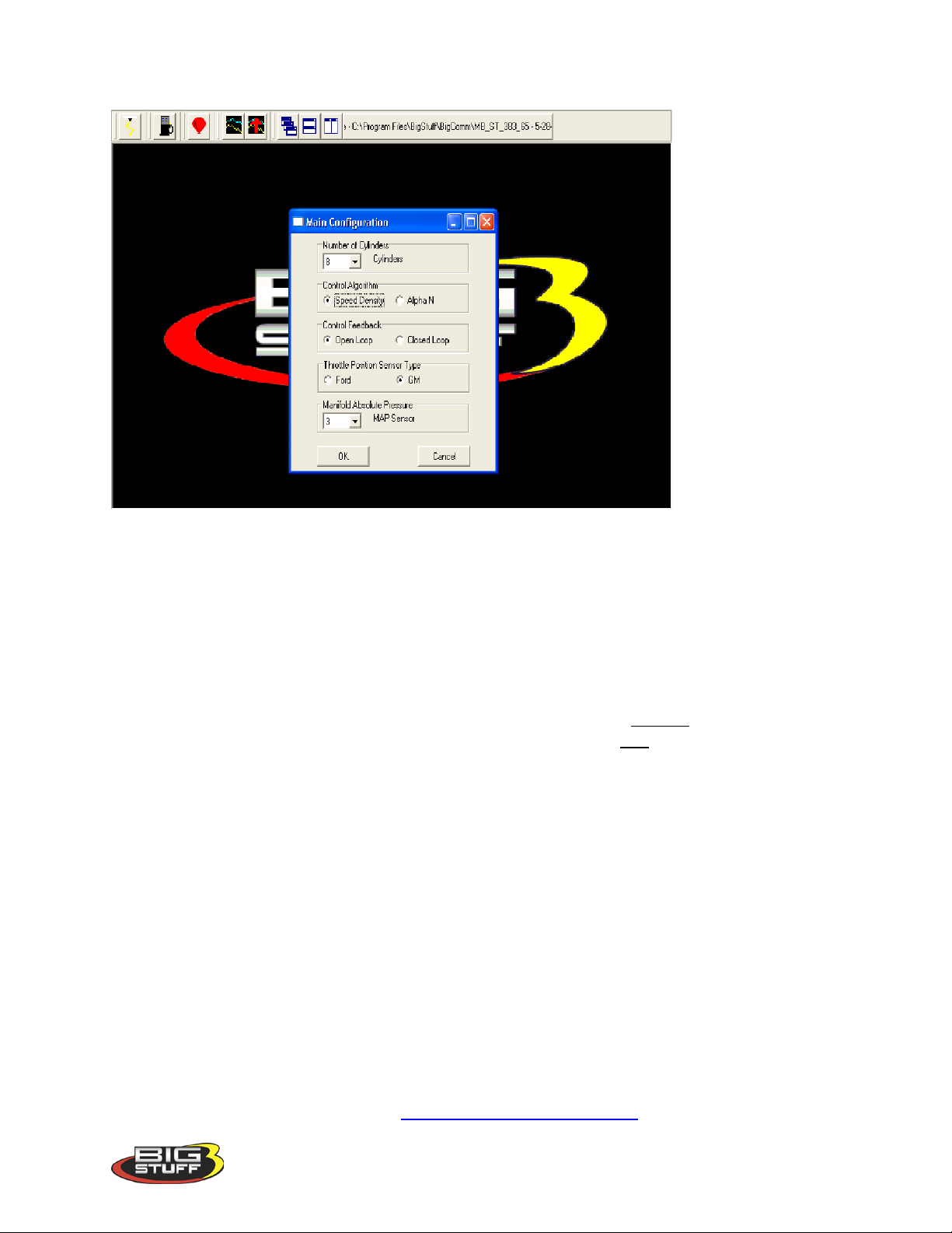
The Hardware Configuration’s Main Configuration table is relatively self-explanatory. Working
from the top of the table, select the parameters shown in the screen print above as follows:
• Select the number of cylinders the engine has.
• Select whether system will operate using a speed density (engine speed and engine load)
or Alpha N (throttle angle and engine speed) algorithm. The majority of the engine
applications use the Speed-Density control algorithm. If the camshaft duration exceeds
0
260
at .050” lift, the Alpha N control algorithm should be considered.
• Select the fuel feed back control configuration. If the engine will not use oxygen (O2)
sensor feedback control, select “Open Loop”. If the engine will use oxygen sensor
feedback, select “Closed Loop”. Note: Air fuel ratio can still be recorded in “Open
Loop” mode.
• Select the type of Throttle Position Sensor (TPS) being used (to output throttle angle to
the ECU). The TPS is located on the side of the throttle body, at the end of the throttle
shaft. GM style TPS sensors have a .5V to 4.5V output. Ford style TPS sensors have a
.9V to 4.5V output. If the sensor type being used is not clear, a dealer should be
contacted before attempting to start and calibrate the engine.
• Lastly, select the Manifold Absolute Pressure (MAP) sensor setting for the application.
For normally aspirated engines, the 1 BAR MAP sensor setting should be selected. For
blown or turbocharged applications a 2 BAR MAP sensor setting must be selected (for
boost pressures up to 15 PSI). For boost pressures up to 30 PSI, the 3 BAR MAP sensor
setting should be selected. For boost pressures up to 52 PSI, the 4 BAR MAP sensor
•
•
• setting should be selected. For boost pressures up to 60 PSI (gage) the 5 BAR MAP
sensor setting should be selected. Contact your dealer to make your system was supplied
with the correct MAP sensor. Return_to_Main_Configuration
Version 1.0 31
Page 33
BigStuff3 Pro SEFI System (LS1)
For setup detail go to
Not needed for LS1
For setup detail go to
For setup detail go to
For setup detail go to
For setup detail go to
For setup detail go to
For setup detail go to
For setup detail go
For setup detail go to
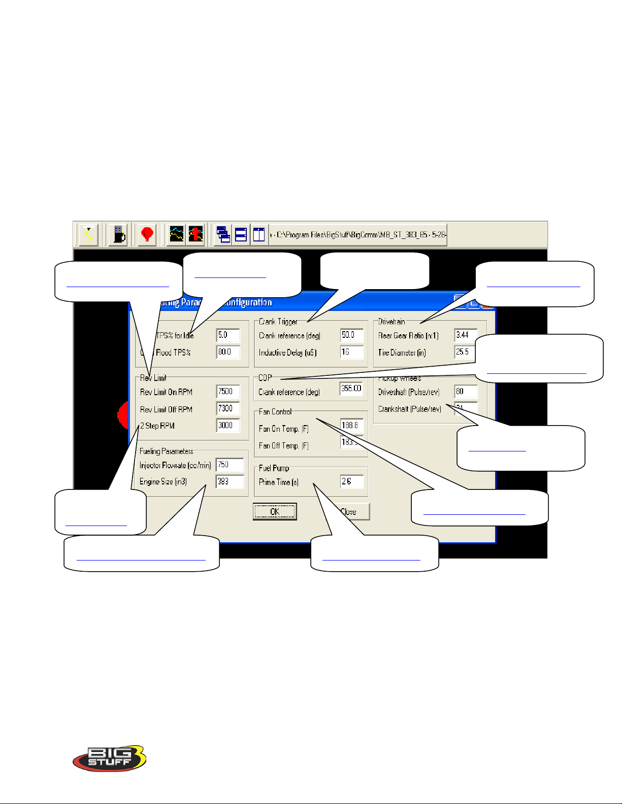
18. Operating Configuration (F5 – “Quick Key”)
Next, the system “Operating Configuration” needs to be set up. From the Main Menu screen
Tool Bar, left click on “Configuration.” Keep the left mouse button depressed and slide the
mouse pointer down until “Operating Configuration” is highlighted. Release the left mouse
button. The screen below will open.
The paragraphs below outline how each operating parameter should be configured. The hyperlinks in the screen-print below link to the instructional text for each subject item.
Rev_Limiter_Configuration
to
Two_Step_RPM
Fueling_Parameters_Configuration
TPS_Configuration
systems
Fuel_Pump_Configuration
Drivetrain_Configuration
Coil-on-Plug (COP)
Crank_Reference_Setup
Pickup_Wheels
Fan_Control_Configuration
Version 1.0 32
Page 34
BigStuff3 Pro SEFI System (LS1)
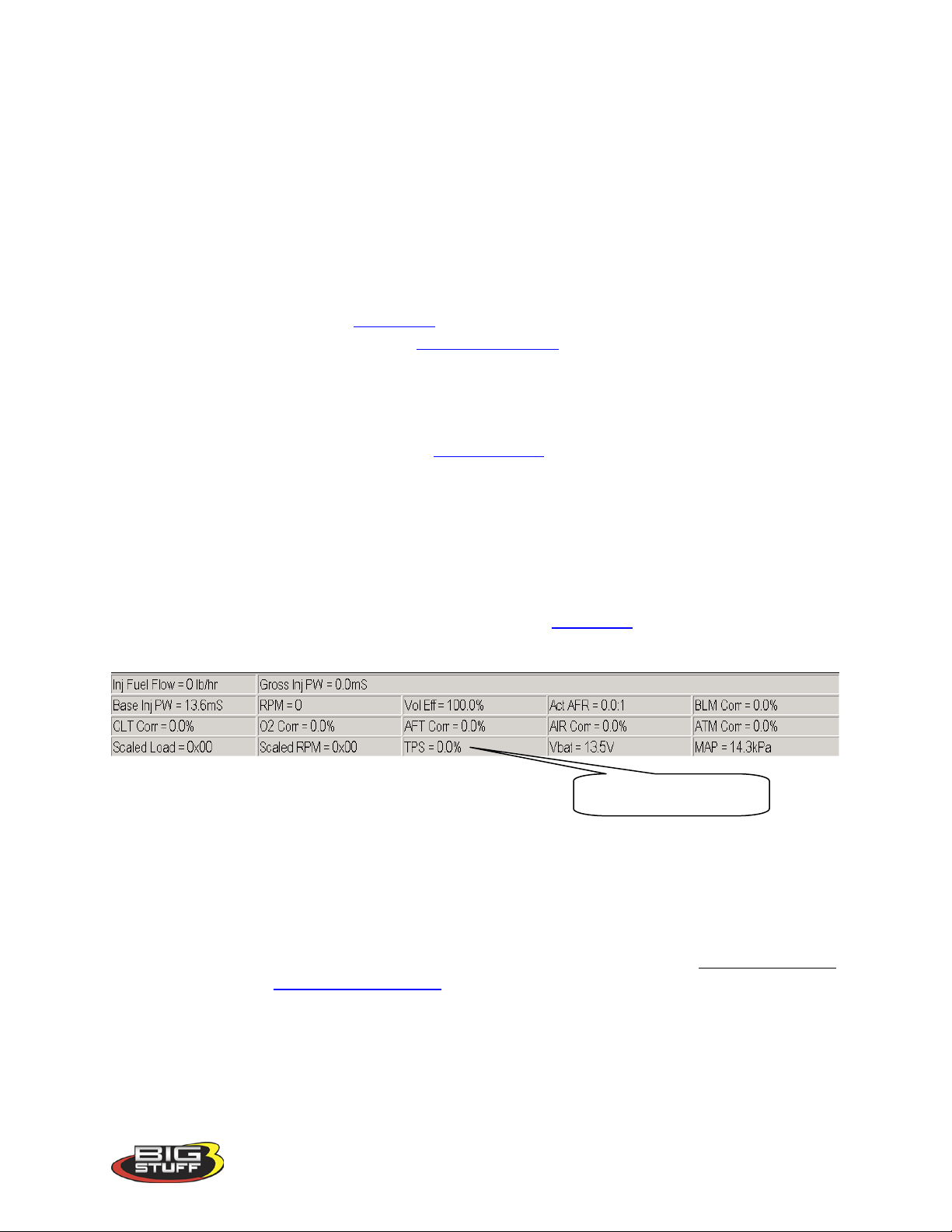
TPS Signal i n the Dash.
TPS Configuration
This input screen allows the user to set:
• The TPS sensor to the correct output voltage when the throttle is completely closed.
• The Clear Flood TPS %, described later in this section.
Note: It is important to have the TPS (%) setup correctly. The TPS sensor (on the throttle
body) and software need to be setup properly to ensure that the full resolution (0% to
100%) of the sensor can be utilized and the following related features function properly
(described later in the manual):
• Idle Spark Control - See Idle_Spark for more information.
• Decel Fuel Cutoff (DFCO) - See dMAP_Parameters for more information
How to Set Max TPS % for Idle
Note: Make sure that the correct type of TPS (GM or Ford) was selected during the hardware
configuration process outlined above. See TPS_Selection.
In the input table set the “Max TPS % for Idle” at 2%. Next, go to the TPS sensor located on
the throttle body. With the throttle blades completely closed and with the engine running at its
normal operating temperature and preferred idle speed, adjust the TPS so that the TPS = % value
shown in the Dash reads between .5% to 1%.
The dashboard can be configured to appear at the bottom of most of the BigComm software
screens. An example of a dashboard is shown below. See Dashboard for more details (described
later in this manual).
How to Set Clear Flood TPS %
Set the Clear Flood TPS % value at 80%. This setting tells the ECU not to add fuel when the
following conditions exist.
o The engine is cranking (between 75 and 400 RPM).
o The throttle position is at 80% or greater (user specified)
If these conditions are met, the ECU does not add fuel. This function is especially useful when
attempting to start a flooded engine. Once the fuel is cleared from the engine, release the throttle
to restart the engine. Return_to_TPS_Setup
Rev Limiter Configuration
This input screen allows the user to set the maximum engine RPM before fuel shutoff occurs.
This setting is referred to as “Rev Limit On RPM”. The screen also includes an input for “Rev
Limit Off RPM,” which is the RPM where fuel will be reintroduced to the engine. A small
RPM band (at least 200 RPM) is required between the “Rev Limit On” and “Rev Limit Off”
Version 1.0 33
Page 35

BigStuff3 Pro SEFI System (LS1)
RPM inputs, so that the engine has a small band (hysteresis) between the rev limiter on and off
limits.
Note: The engine may not run if there is no band between the On and Off limits or the
RPM inputs are reversed! For example, if the “Rev Limit On” is set for 7,100 RPM and the
“Rev Limit Off” is set at 7,300 RPM the engine will not run. Return_to_Rev_Limiter_Setup
2-Step RPM
When 12 Volts is applied to Main Header Connector pin B2, the ECU will begin rev limiting the
engine to the 2-Step RPM setting in the Operating Parameters Configuration input window.
Return_to_Two_Step_RPM
Fueling Parameters Configuration
This screen requires the user to input the fuel injector flow rate and the engine displacement (in
cubic inches!). The user needs to know these inputs (contact your dealer for further assistance).
If the injector flow rate, in pounds per hour (lbs./hr.) is known, the flow rate in cubic
centimeters/minute (cc/min.) can be calculated by multiplying the lbs/hr rate by 10.
Return_to_Fueling_Parameters_Setup
Engine Cooling Fan Control Configuration
This input screen allows the user to set the coolant temperature that the GEN3 ECU will turn the
engine-cooling fan on (Fan On Temp) and off (Fan Off Temp). The Fan Off temperature should
be ~ 5 o to 10o less then the Fan On temperature. Return_to_Fan_Control_Setup
Fuel Pu mp Configuration
This input screen allows the user to set the amount of time the fuel pump will run when the
ignition is turned to the “On” position. This allows the user time to prime the fuel pump and
check for leaks before the engine is started. A time period of up to 25 seconds can be inputted
into this screen.
Return_to_Fuel_Pump_Setup
Drivetrain Configuration
The vehicle final drive ratio and tire diameter inputs are required to enable the ECU to make the
correct Mile-Per-Hour (MPH) calculations.
Return_to_Drivetrain_Setup
Pickup Wheels
Drive Shaft Configuration (Pulse/rev)
This input screen allows the user to set the quantity of teeth on the transmission output shaft.
This input is part of the MPH calculation made by the ECU. For reference, the GM 4L60E and
4L80E transmissions have 40 teeth tone rings on their output shafts. Return_to_Pickup_Wheels
Version 1.0 34
Page 36

BigStuff3 Pro SEFI System (LS1)
Crank Shaft (Pulse/rev)
This input screen allows the user to set the quantity of teeth on the crankshaft.
Return_to_Pickup_Wheels
Coil-On-Plug (COP)
Crank Reference Setting
To realize the full benefits of the GEN3’s precise timing and individual cylinder control, Top
Dead Center (TDC) for cylinder 1 (compression stroke) needs to be determined and marked on
the dampener.
Finding TDC
TDC is the point at which the number 1 piston reaches its uppermost position in the cylinder.
Ignition timing is usually expressed as degrees before top dead center (BTDC) or after top
dead center (ATDC). A timing mark on the crankshaft balancer or dampener corresponds to
the top dead center position of the number one engine cylinder. In order for the GEN3 ECU
to reach its full performance potential, it is important that TDC is verified. A simple process
for verifying TDC for number one (1) cylinder (compression) is outlined in the paragraphs
below.
Finding TDC Process to use when the cylinder heads are on the engine
One way to find Top Dead Center (TDC) is to use a piston stop and a degree wheel. Make
sure that the piston is down in the cylinder and then thread the piston stop into the #1 spark
plug hole. Securely fasten the degree wheel to the front of the crankshaft. Next, fabricate a
rigid pointer to point at the front of the degree wheel. Make sure that the pointer is solidly
mounted so that it will not move. Using a ½ breaker bar, very slowly and carefully rotate the
crankshaft until the piston lightly touches the piston stop. Write down the number the pointer
is indicating on the degree wheel. Rotate the crankshaft in the opposite direction again until
the piston lightly touches the piston stop. Again, write down the number the pointer is
indicating on the degree wheel. TDC will be exactly in between the two numbers that were
recorded. Remove the piston stop and rotate the motor the “middle” number on the degree
wheel.
A new zero point mark (white paint works well) needs to be made on the dampener. Once
made, this new line will represent true TDC when it is in exact alignment with pointer.
Crane Cams offers positive stops (brass), in 12mm (Part number 99410-1) & 14mm (Part
number 99412-1) sizes. GM also offers a piston stop (Part number 12364087). They are
made to screw directly into the cylinder head spark plug hole and are machined from brass to
prevent piston damage. They incorporate an air bleed hole to prevent compression build-up
while turning the engine over.
If the cylinder heads are off the engine, Use the same process as outlined above, except use a
dial indicator instead of a piston stop.
Version 1.0 35
Page 37
BigStuff3 Pro SEFI System (LS1)
Setting the LS1 Crank Reference
Now that TDC for the number one (1) cylinder (compression) has been determined, the next step
is to determine the 1
st
crank falling edge after the cam falling edge. A voltmeter is required to
perform this task. A crankshaft degree wheel is also recommended.
The following paragraphs outline the process steps.
• Roll the crankshaft back 30
o
Before Top Dead Center (BTDC). A crankshaft degree
wheel or balancer timing tape will help expedite the process. If neither is available, the
following formula can be used to measure the distance, on the surface of the balancer that
equals 30
o
.
Multiply the diameter of the balancer by 3.14. Divide the result by 360, and
then multiply by 30 (representing the 30
o
).
Example based on a 7” balancer: 7 x 3.14= 21.98. 21.98/360= .06105” (per
degree). .06105” x 30o =1.8316”. From the TDC mark on the balancer,
measure forward (clockwise) about 1-13/16” and make a mark, which will
represent 30
o
BTDC.
• Next, make sure the main wire harness camshaft connector is attached to the stock LS1
camshaft sensor and the main wire harness Switched 12-Volt wire is connected and
“live”. The main harness battery connections also must be in place.
• Attach the Voltmeter’s red lead to the main wire harness terminal E3 (Signal) and the
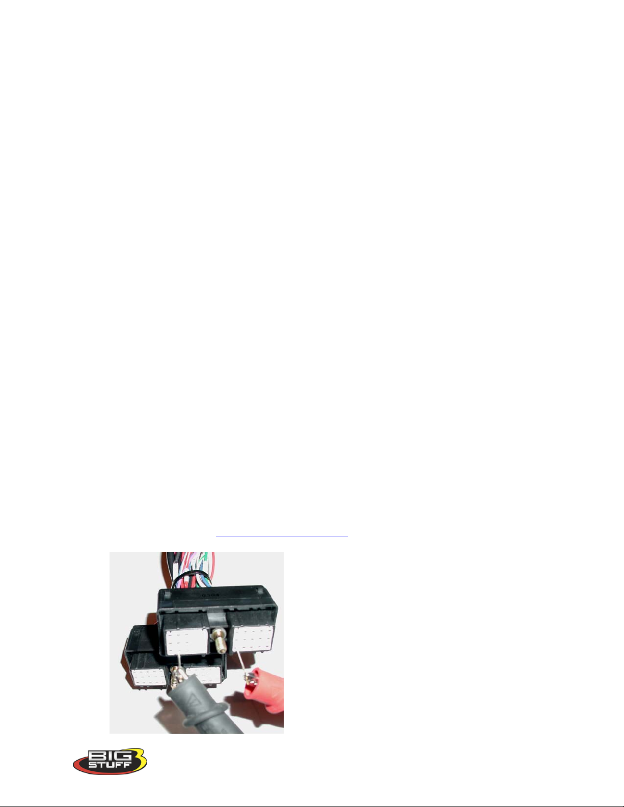
Voltmeter’s black lead to the main wire harness terminal J2 (Gnd). These terminals are
attached to wires routed back to the camshaft sensor. The easiest way to accomplish this
is to insert sewing needles between the Voltmeter’s positive and negative alligator
clamps, and then push them into the aforementioned header connector terminals.
Note: Make sure the probes (sewing needles) inserted into the E3 and J2 terminals do not
touch each other. Doing so will damage the main wire harness!
Note: It is important to use probes with tapered tips (like sewing needles) rather than
blunt tipped probes (like paper clips) to avoid damaging the main harness header
connector terminals. Return_to_Pickup_Wheels
Version 1.0 36
Page 38

BigStuff3 Pro SEFI System (LS1)
• Rotate the crankshaft back to 30
o
BTDC position and the voltmeter attached to the E3 and
J2 terminals, the voltmeter should read 12 Volts (the Switched 12-Volt wire on the main
harness must be is connected and “live”).
• Very slowly, rotate the crankshaft clockwise towards TDC. As soon as the voltmeter
reading drops to zero Volts (or very close to zero Volts) stop rotating the crankshaft.
• Next, make sure the main wire harness crankshaft connector is attached to the stock LS1
crankshaft sensor and the main wire harness, Switched 12-Volt wire is connected and
“live”.
• Attach the Voltmeter’s red lead to the main wire harness terminal J3 (Signal). Leave the
Voltmeter’s black lead inserted into the main wire harness header connector terminal J2
(Gnd). These terminals are attached to wires routed back to the crankshaft sensor.
Again, make sure the probes (sewing needles) inserted into the J3 and J2 terminals do not
touch each other. Doing so will damage the main wire harness! The voltmeter should
read 12 Volts.
• Very slowly, rotate the crankshaft clockwise. As soon as the voltmeter reading drops to
zero Volts (or very close to zero Volts) stop rotating the crankshaft.
• Take the crankshaft reading. If the crankshaft (balancer) TDC timing mark is after TDC
(ATDC) e.g. 10o, input 350o (360o - 10o = 350o) into the Crank Reference input box. If
the crankshaft timing mark is before TDC, add the value, e.g. 10o to 360o (360o + 10o =
o
370
) into the Crank Reference input box.
• Lastly, it is important to confirm that the timing at the crank, when the engine is running,
is equal to the values in the spark table. Set all the values in the spark table to thirty (30)
degrees and then make sure the balancer mark, representing 30
o
lines up with the pointer.
• Note: The crank reference table has ¼ degree resolution.
19. Dwell Time Table
The dwell time affects the amount of primary current in the ignition coil. The longer the coil
dwell the more primary current available for a spark event. GM coils are current limited at 6
Amps to 7 Amps. GM coils reach their current limit at approximately 6 ms of dwell time.
BigStuff’s GEN3 ECU allows for coil saturation at high RPM, where maximum spark energy is
required, but also allows the coils to run at lower dwell times (ms), at lower RPM, to avoid
overheating the coils.
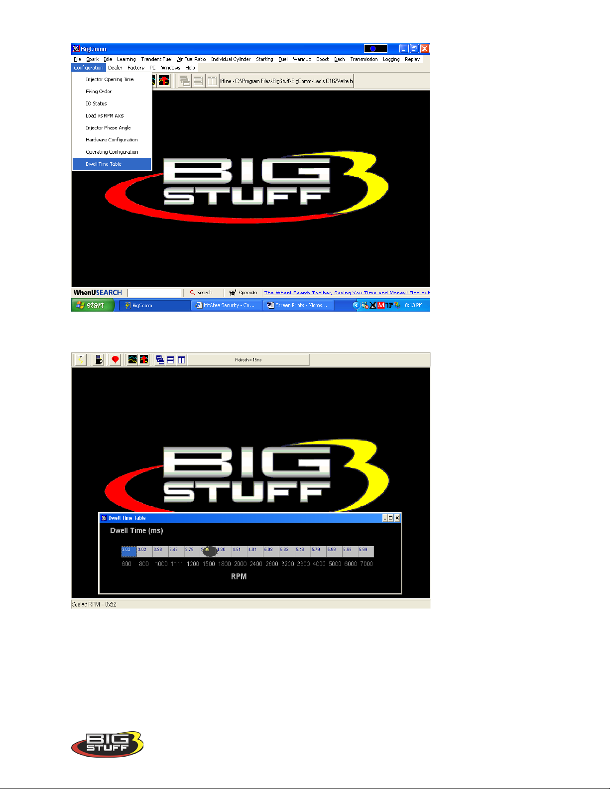
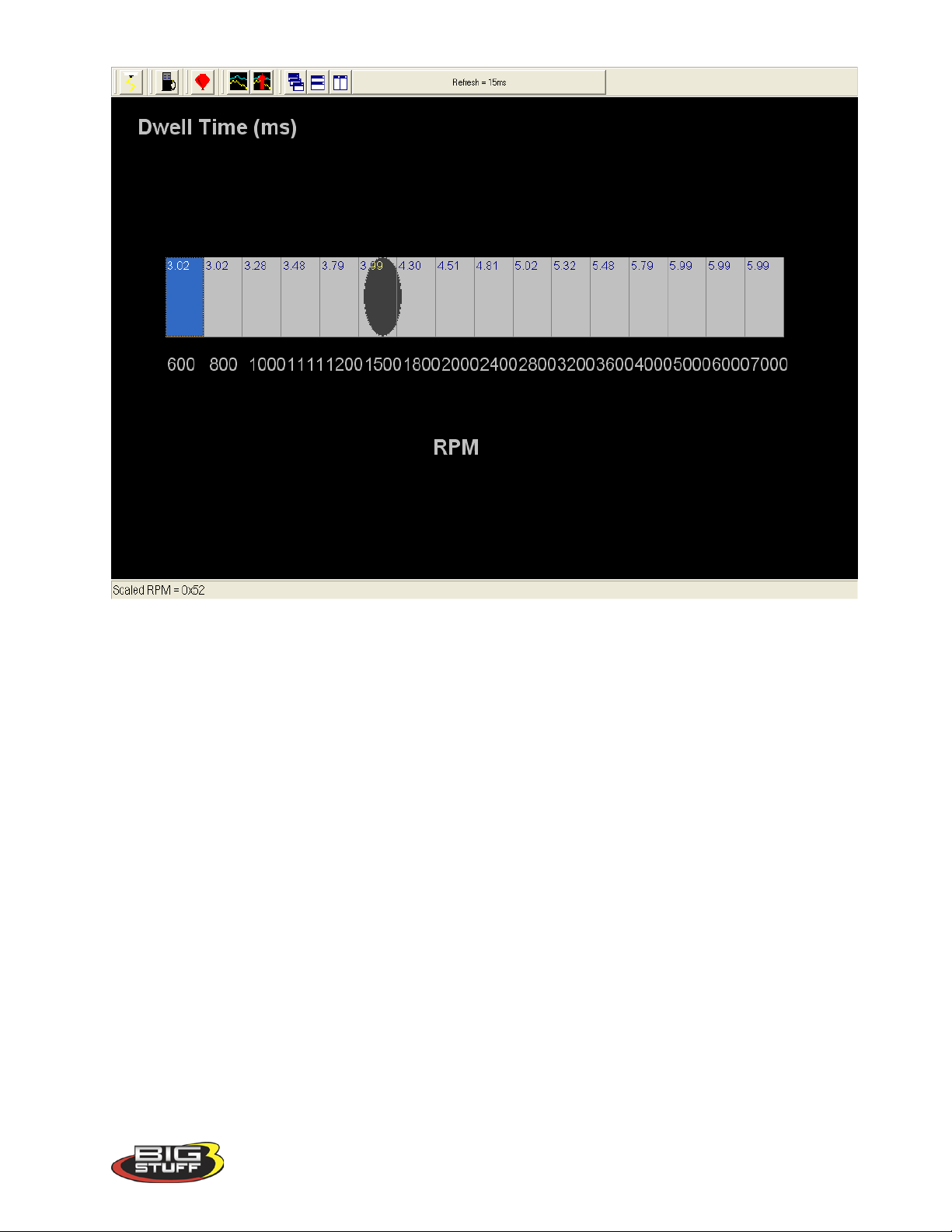
The 1 x 16 table allows coil dwell-time to be set as a function of engine RPM.
Note: The RPM values, at the bottom of the dwell-time input table, are established when the
Load vs. RPM Axis table is configured.
Version 1.0 37
Page 39
BigStuff3 Pro SEFI System (LS1)
An example of a default table, supplied with the system, is shown below.
This is the same table as is shown above with the window maximized.
Version 1.0 38
Page 40
BigStuff3 Pro SEFI System (LS1)
20. Load vs. RPM
The BigStuff3 GEN3 SEFI system offers configurable Load & RPM axes! This feature is not
available on any other comparably priced systems!
Version 1.0 39
Page 41
BigStuff3 Pro SEFI System (LS1)
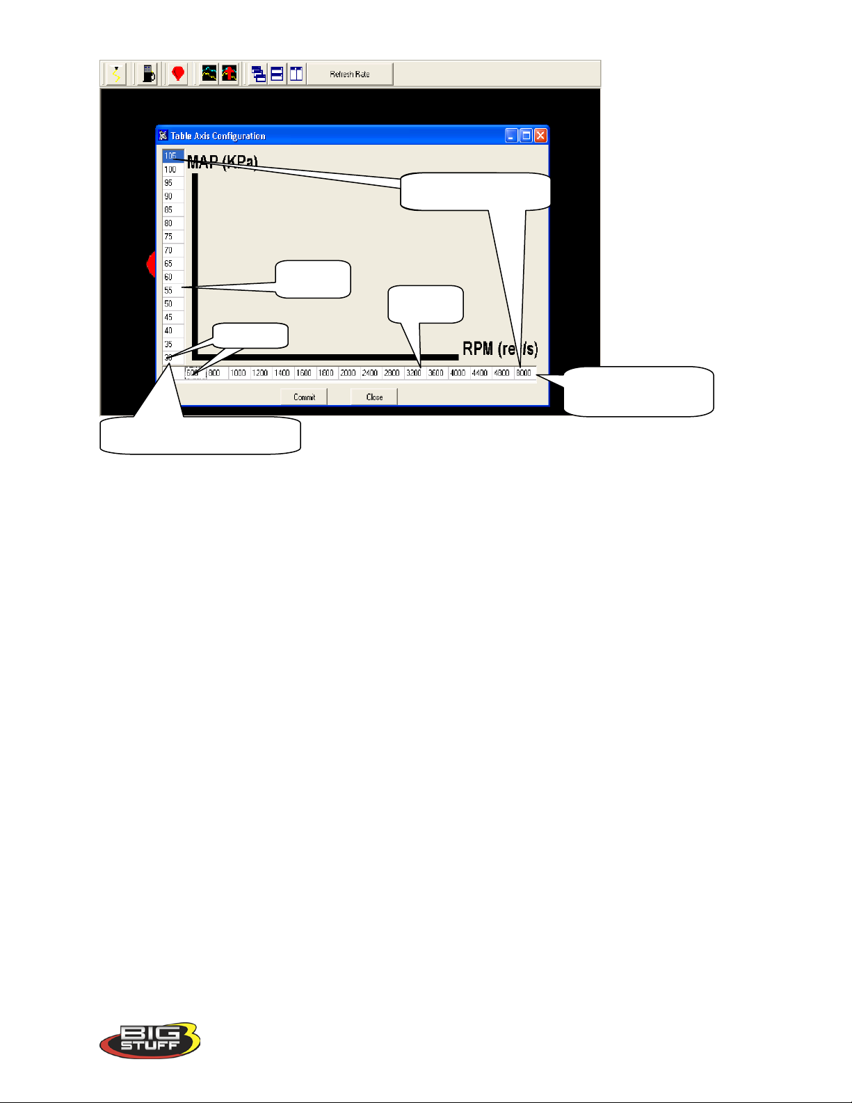
This feature allows the user to configure the X axis (RPM) and Y Axis (Load), so that a majority
of the available16 cell by 16 cell fuel and spark map area is available for calibrating. Systems
with fixed X & Y axes allow only a small portion of the available map area to be used to
calibrate the fuel and spark needs of the engine.
This capability is extremely important if the engine is fuel or spark sensitive at a given load
and/or RPM. For example, if the engine/transmission/rear gear combination makes the engine
sensitive to throttle changes at 2,200 rpm, the user can configure the X-axis in 200 or 300-RPM
increments at or around 2,200 RPM.
If the “Speed Density” control algorithm was selected during the aforementioned Hardware
Configuration step, the screen should show MAP (kPa) in the Y axis and RPM in the X axes. If
the screen shows TPS % and the preferred control algorithm is “Speed Density,” go back to
Main_Configuration and select Seed Density instead of Alpha N.
Version 1.0 40
Page 42
BigStuff3 Pro SEFI System (LS1)
Cell Number 16
Cell 1
Scaled RPM Axis
Scaled Load Axis (Y-Axis)
Y-Axis
X-Axis
(X- Axis)
“Scaled” RPM inputs from this table define the RPM break points used in the following tables, to name a few, which are described later in this manual!!!
• Dwell Time Table
• Injector Phase Angle (degree) Table
• Boost Spark (retard) Table
• Starting Line Timing Table
Version 1.0 41
Page 43

BigStuff3 Pro SEFI System (LS1)
Load Schedule
Engine)
16
106
205
300
500
15
100
195
275
450
14
95
180
250
400
13
90
165
225
350
12
85
150
200
300
11
80
135
175
25
10
75
125
150
200 9 70
115
125
175
8
65
105
110
150
7
60
95
100
125 6 55
85
90
100
5
50
75
80
90 4 45
65
70
80 3 40
55
60
70 2 35
45
50
60
1
30
35
40
50
RPM Schedule for a
RPM)
16
5,200
6,000
9,500
15
4,800
5,500
9,000
14
4,400
5,000
8,500
13
4,000
4,500
8,000
12
3,600
4,000
7,500
11
3,200
3,600
7,000
10
2,800
3,200
6,500
9
2,400
2,800
6,000
8
2,000
2,400
5,000
7
1,800
2,100
4,000
6
1,600
1,800
3,500
5
1,400
1,500
3,000
4
1,200
1,200
2,500
3
1,000
1,000
2,000
2
800
800
1,500
1
600
600
1,000
The following table offers default Load schedules for 1, 2, 3, & 5 BAR MAP sensor applications.
MAP (KPa)
(Y Axis)
Cell Number
for 1 BAR MAP
Sensor
(Normally
Aspirated
Load Schedule
for 2 BAR MAP
Sensor (Up to
15 PSI of Boost)
Load Schedule
for 3 BAR MAP
Sensor (Up to
30 PSI of Boost)
Load Schedule
for 5 BAR MAP
Sensor (Over 30
PSI of Boost)
The following table offers default RPM Schedules for several engine configurations.
RPM (Y Axis)
Cell Number
RPM Schedule for a
Stock (Torque)
Engine
RPM Schedule for a
Mild Street Engine
(6,500 Max RPM)
High RPM Racing
Engine (9,500 Max
Version 1.0 42
Page 44
BigStuff3 Pro SEFI System (LS1)
21. Firing Order
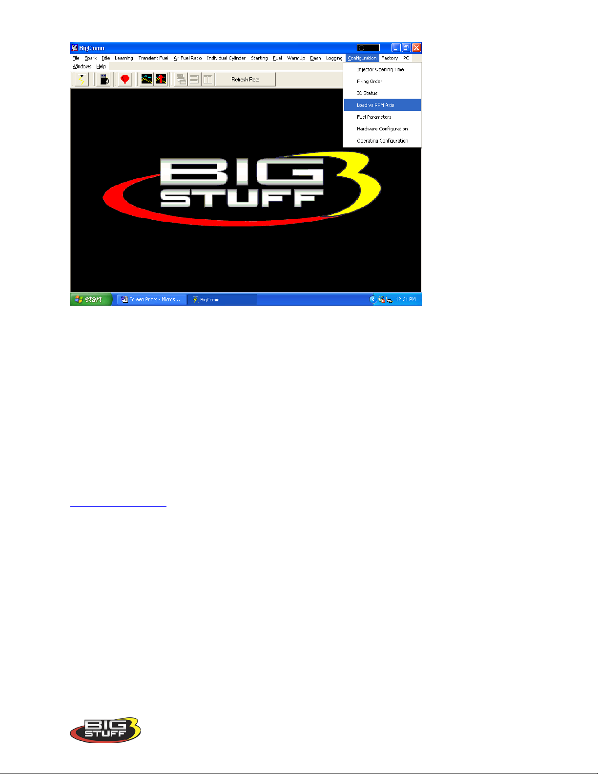
Once the Load and RPM axes have been configured, go back to the Configuration on the Tool
Bar. Left click on the “Configuration” and the drop down screen will open. Keep the left
mouse button depressed and slide the mouse pointer down until “Firing Order” is highlighted.
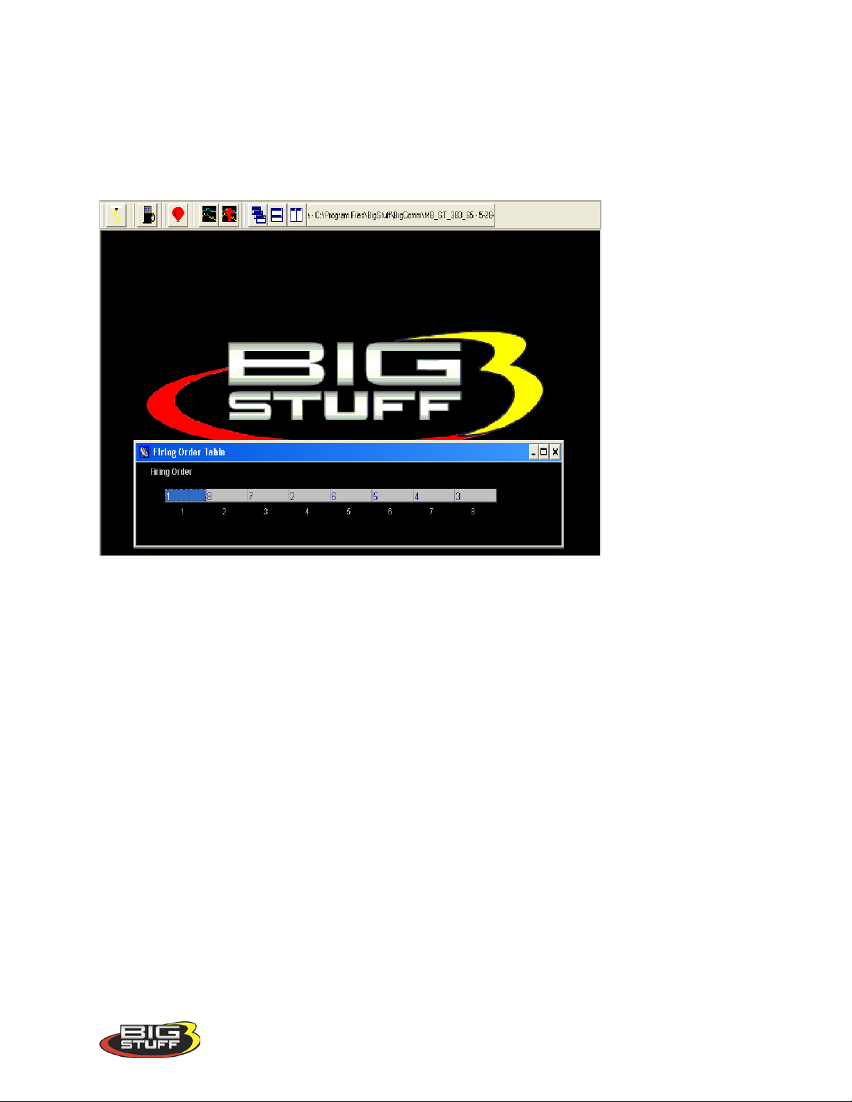
Release the left mouse button. The screen below will open.
Setting the Firing Order
To set the firing order, simply work from left to right and input the firing order of the engine the
system is installed on. The LS1 firing order (1-8-7-2-6-5-4-3) is shown in the example above.
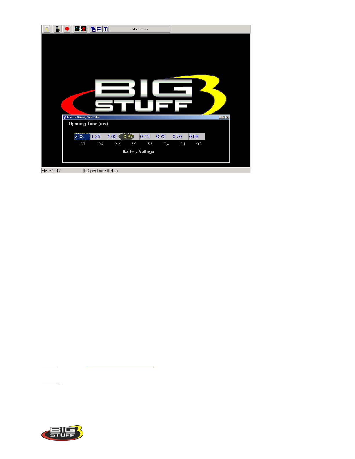
22. Injector Opening Time
Next, go back to Configuration on the Tool Bar. Left click on the “Configuration” and the
drop down screen will open. Keep the left mouse button depressed and slide the mouse pointer
down until “Injector Opening Time” is highlighted. Release the left mouse button. The screen
below will open.
Version 1.0 43
Page 45
BigStuff3 Pro SEFI System (LS1)
The purpose of this table is to allow the user to configure the ECU to maintain a constant injector
flow rate with varying battery voltages.
Fuel injectors have a minimum pulse width (in milliseconds) required before they will open and
let fuel flow. For example, with a constant battery voltage of 13.4V, a 60 lb/hr. Bosch injector is
not likely to open until the ECU sends a pulse width command of 1.4 to 1.5 milliseconds
(injector opening time is also influenced by fuel pressure).
At a given voltage, the minimum pulse width required to open an injector will vary based on
injector size, injector type and manufacturer. This input screen allows the user the ability to fine
tune flow rates (injector opening time) based on battery voltage.
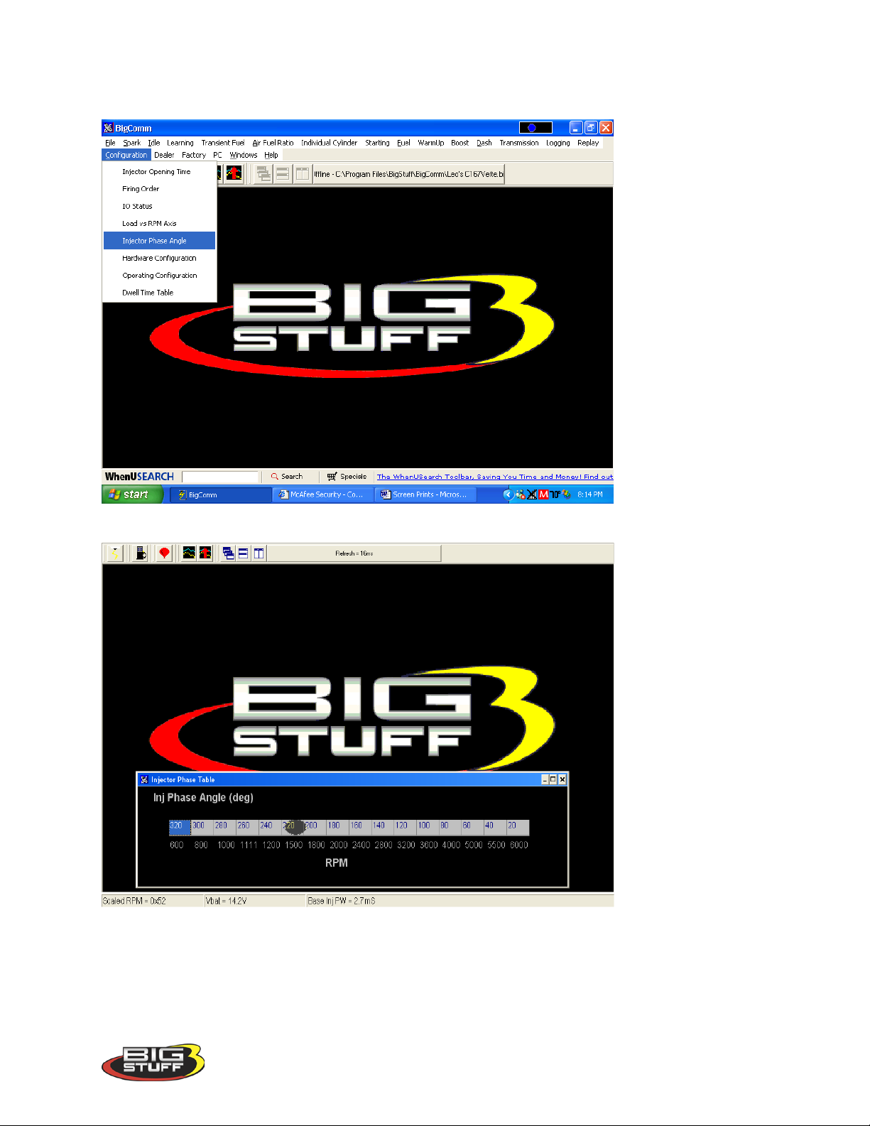
23. Injector Phase Angle
Injector Phase Angle setting allows the ECU to “time” the fuel delivery relative to the intake
valve opening!
To calculate the actual Start of Injection (SOI) use the following equation:
360o - (minus) LS1 “Crank Reference” + (plus) “Phase Angle”. The
o
360
- 350
10 o
+290 o Input from Injector Phase table. Accessed from Configuration drop down.
300
The major benefit of this feature is realized when using high flow injectors with a smaller duty
cycle.
o
See LS1 Crank_Reference_Setup accessed from Operating Configuration table.
o
Version 1.0 44
Page 46
BigStuff3 Pro SEFI System (LS1)
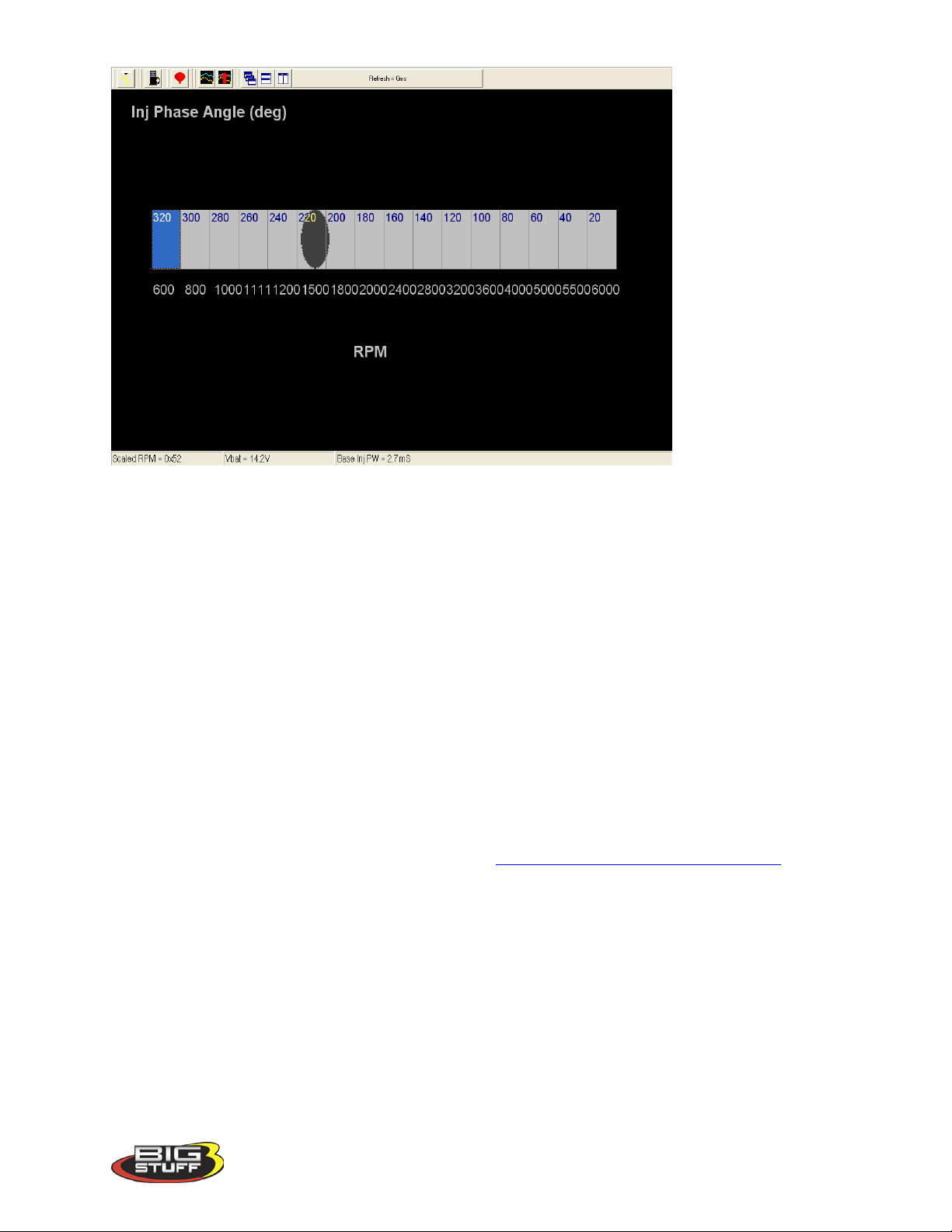
Note: The RPM values, at the bottom of the table, are from the Load vs. RPM Axis drop down
accessible from the Configuration tab from the Main Menu screen.
Same screen print as is shown above with window maximized.
Version 1.0 45
Page 47
BigStuff3 Pro SEFI System (LS1)
You have now reached a milestone! The following necessary tasks have been completed:
• The BigComm software has been installed
• Communication with the ECU has been established.
• The hardware and operating parameters have been configured.
The following sections of the manual will outline how to use the Air/Fuel Ratio table, O2
Correction tables and the Fuel Table. Calibrating the engine for steady state operation is an
iterative process using these tables.
The fuel calibration process, in order of importance, is as follows:
• The air/fuel ratio table will be configured to desired ratios for the different engine speed
and load combinations.
• The positive and negative O2 correction tables will be configured.
• The volumetric efficiency (VE) values in the Fuel Table will be calibrated.
Once these tables are configured, as a baseline, the Calibrating_with_the_Trace_Function (a
great feature) can be used to fine tune the interrelationships of the aforementioned tables. The
“Trace” function allows the engine to be quickly calibrated “On-line” (ECU powered up) or
“Off-Line” (PC only). The Trace Function will be explained later in this manual.
Version 1.0 46
Page 48
BigStuff3 Pro SEFI System (LS1)
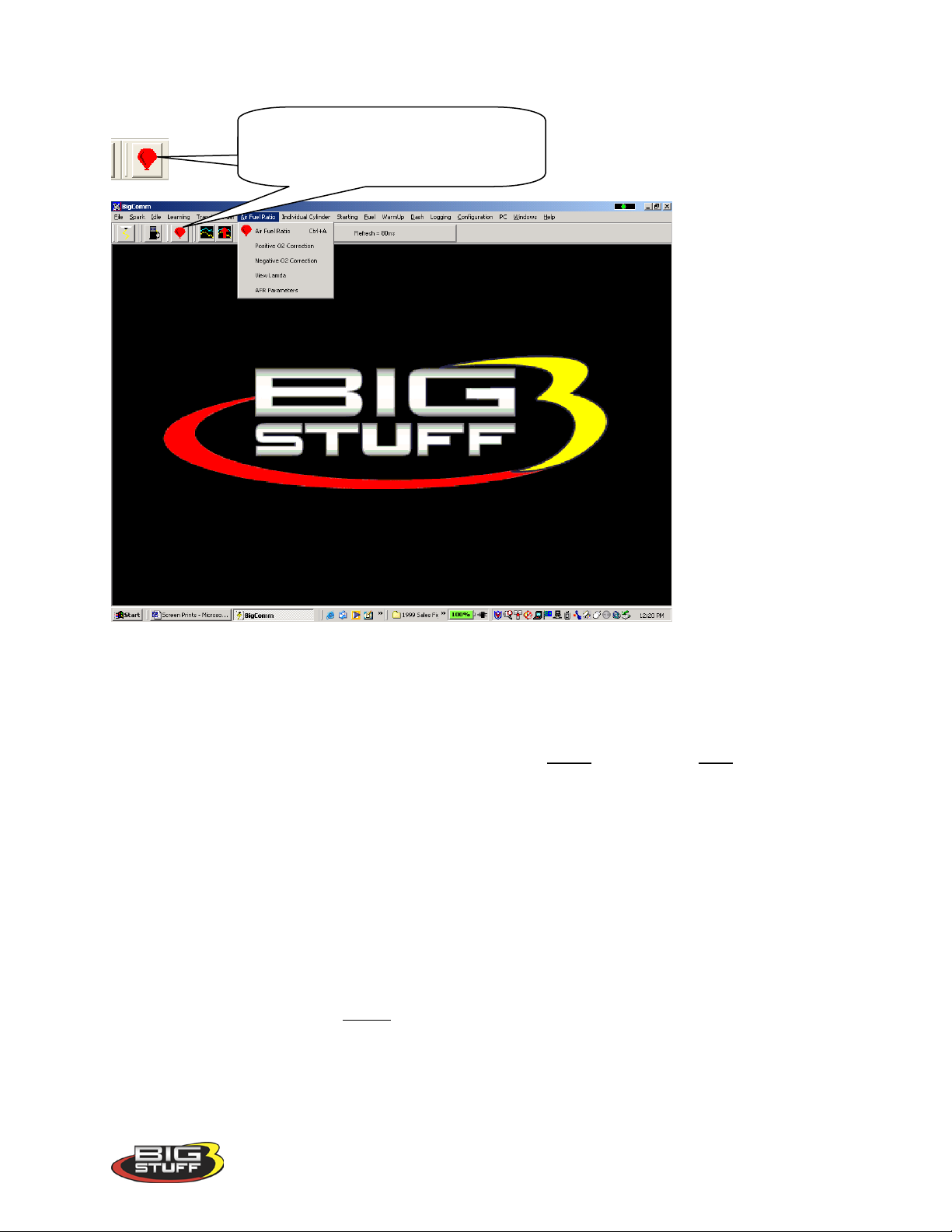
Use the air/fuel icon to quickly access the
24. AIR FUEL RATIO (F11 – (“Quick Key”)
air/fuel ratio table. The F11 “Quick Key”
can also be used.
25. Air Fuel Ratio Table
Note: In most cases, the ECU shipped with your system will come pre-configured with a table,
which will closely match your engine configuration. The air fuel ratio table below allows the
user to input desired air/fuel ratios for sixteen (16) engine speed (RPM) and 8 load (MAP or
TPS) combinations. The X-axis represents engine RPM and allows for 16 inputs and the Y-axis
represents engine load and allows for 8 inputs. For each speed and load combination (cell) the
engine operates within, the ECU uses the WBO2 sensor feedback to achieve the desired air/fuel
ratio for that cell.
While the engine is running, a “real-time Ellipse” will move throughout the Air Fuel Ratio table
relative to the current RPM & Load “operating point”. Use it as a point of reference to help
calibrate the Air Fuel Ratio table.
To change a cell value in the Air Fuel Ratio table, move the cursor using the PC’s mouse or the
arrow keys to the cell to be changed. Click on the cell and type a desired Air Fuel Ratio value
(from to 10.5 to 15.0) and hit “Enter” to save the change.
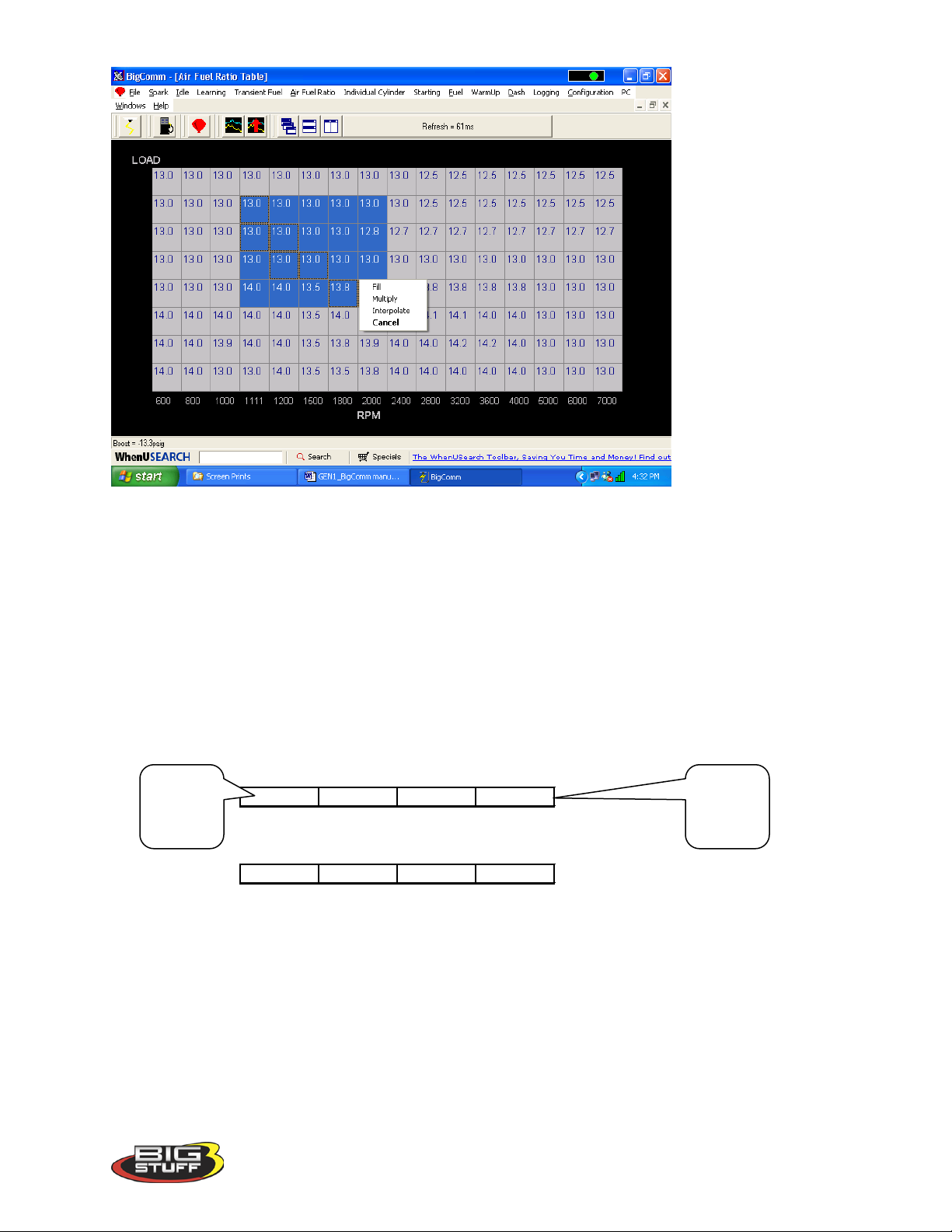
To make changes to multiple cells simultaneously, left mouse click and drag the cursor (down
and to the right) across the cell range to be changed. Release the left mouse button and a
secondary drop down screen will appear outlining three potential “cell fill” options
Version 1.0 47
Page 49
BigStuff3 Pro SEFI System (LS1)
Cell Values Selected in a Row
14 14 13.5 13.8
Interpolated Result from Cell Values Selected Above
14 13.9 13.8 13.8
Cell
Cell
• Fill – Choosing “Fill” will open a secondary drop down- screen which allows the selected
cells to be changed to the value inputted into the window.
• Multiply – Choosing “Multiply” will open a secondary drop down-screen which allows
the values of the selected cells to be changed by the ” Multiply” value inputted into the
window. For example, if the values in the cells selected are 13 and the inputted
“Multiply” value was 80, the new cell values would be 10.4.
• Interpolate – If a series of cells in the same row are selected and the “Interpolate” “cell-
fill” option is selected the ECU will use the value in the cell all the way to the left and the
cell value all the way to the right and interpolate the numbers in between so that the
values are linear.
value to
the left
If a series of cells in the same column are selected and the “Interpolate” option is selected the
ECU will use the value in the cell all the way at the bottom and the cell value all the way at the
top and interpolate the numbers in between so that the values are linear.
Version 1.0 48
value to
the left
Page 50

BigStuff3 Pro SEFI System (LS1)
Cell Values Selected in a Column
131314
13.9
Interpolated Result from Cell Values Selected Above
13
13.3
13.6
13.9
Range of Cell Values Selected
13 13 13 13
13.8 13.8 13.8 13.8
14.1 14.1 14 14
14 14.2 14.2 14
Interpolated Result from Range of Cell Values Selected Above
13 13 13 13
13.3 13.3 13.3 13.3
13.6 13.6 13.6 13.6
14 14 14 14
If a range of cells (multiple rows and columns) are selected and the “Interpolate” “cell-fill”
option is selected the ECU will use the value in the cells at the bottom left and top left corners,
bottom left and bottom right corners and the bottom left and top right corners of the entire range
and interpolate the numbers in between so that the values are linear.
• Cancel – Hit cancel to disregard making any changes.
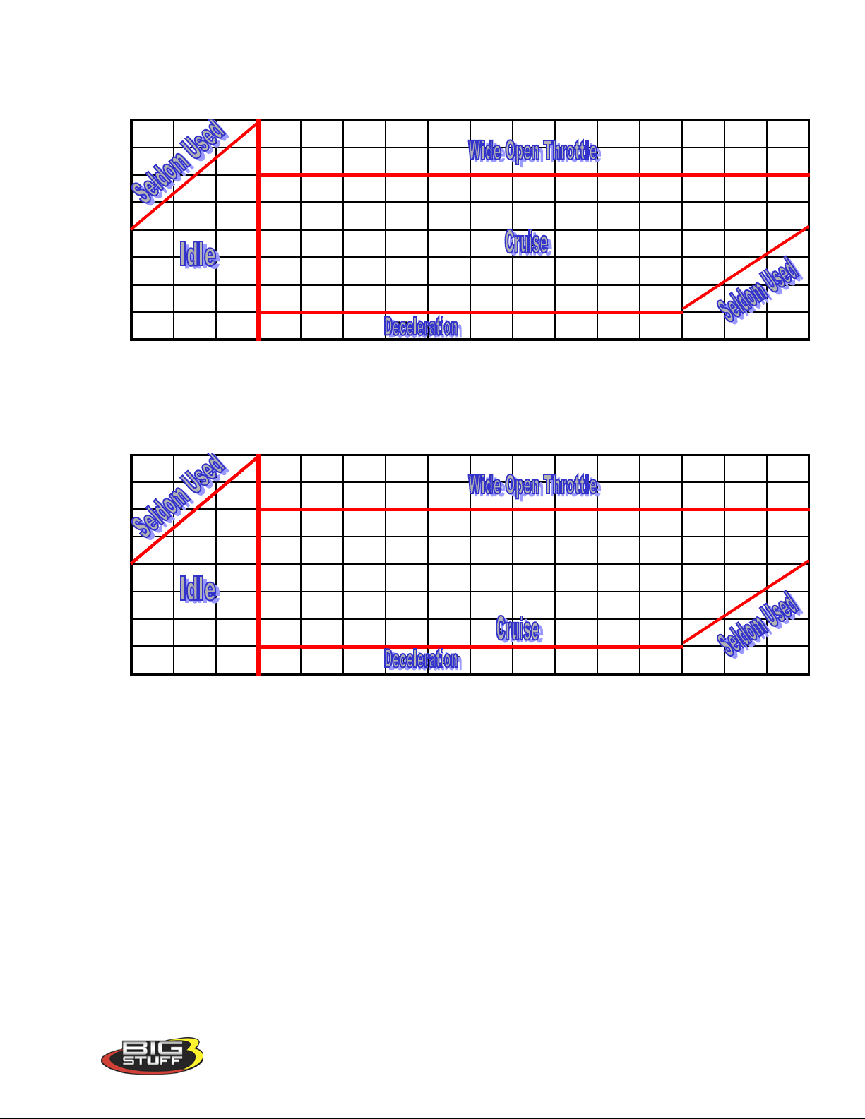
Example Air Fuel Ratio Tables
Example air fuel ratio tables, for a normally aspirated street engine, a super charged engine and a
turbocharged engine, are shown below. The air/fuel ratio values in these cells can be used as
base lines for each of the engine configurations. The “Example Maps” below are segmented into
engine operating areas (Cruise, Idle, Wide Open Throttle, etc.) to help the user understand what
part of the map is “active” under different driving conditions (engine speed and load
combinations).
Version 1.0 49
Page 51
BigStuff3 Pro SEFI System (LS1)
Normally Aspirated Street Engine
13.1 13.1 13.1 13.1 13.1 13.1 13.1 13.1 13.1 13.1 13.1 13.1 13.1 13.1 13.1 13.1
13.5 13.5 13.5 13.5 13.5 13.5 13.5 13.5 13.5 13.5 13.5 13.5 13.5 13.5 13.5 13.5
14 14 14 14 14 14 14 14 14 14 14 14 14 14 14 14
14.5 14.5 14.5 14.5 14.5 14.5 14.5 14.5 14.5 14.5 14.5 14.5 14.5 14.5 14.5 14.5
14.5 14.5 14.5 14.6 14.7 14.7 14.7 14.7 14.7 14.7 14.7 14.7 14.7 14.7 14.7 14.7
LOAD
14.5 14.5 14.5 14.6 14.7 14.7 14.7 14.7 14.7 14.7 14.7 14.7 14.7 14.7 14.7 14.7
14.5 14.5 14.5 14.6 14.7 14.7 14.7 14.7 14.7 14.7 14.7 14.7 14.7 14.7 14.7 14.7
14.5 14.5 14.5 14.7 14.7 14.7 14.7 14.7 14.7 14.7 14.7 14.7 14.7 14.7 14.7 14.7
600 800 1,000 1,100 1,200 1,500 1,800 2,400 2,800 3,000 3,500 4,000 4,500 5,200 5,500 6,000
RPM
Super Charged Engine (15 PSI)
11.5 11.5 11.5 11.5 11.5 11.5 11.5 11.5 11.5 11.5 11.5 11.5 11.5 11.5 11.5 11.5
11.75 11.75 11.75 11.75 11.75 11.75 11.75 11.75 11.75 11.75 11.75 11.75 11.75 11.75 11.75 11.75
12 12 12 12 12 12 12 12 12 12 12 12 12 12 12 12
13 13 13 13 13 13 13 13 13 13 13 13 13 13 13 13
13.5 13.5 13.5 13.5 13.5 13.5 13.5 13.5 13.5 13.5 13.5 13.5 13.5 13.5 13.5 13.5
LOAD
14 14 14 14 14 14 14 14 14 14 14 14 14 14 14 14
14.6 14.6 14.6 14.6 14.7 14.7 14.7 14.7 14.7 14.7 14.7 14.7 14.7 14.7 14.7 14.7
14.7 14.7 14.7 14.7 14.7 14.7 14.7 14.7 14.7 14.7 14.7 14.7 14.7 14.7 14.7 14.7
600 800 1,000 1,150 1,200 1,500 1,800 2,000 2,400 2,800 3,200 3,600 4,000 5,000 6,000 7,000
RPM
Version 1.0 50
Page 52
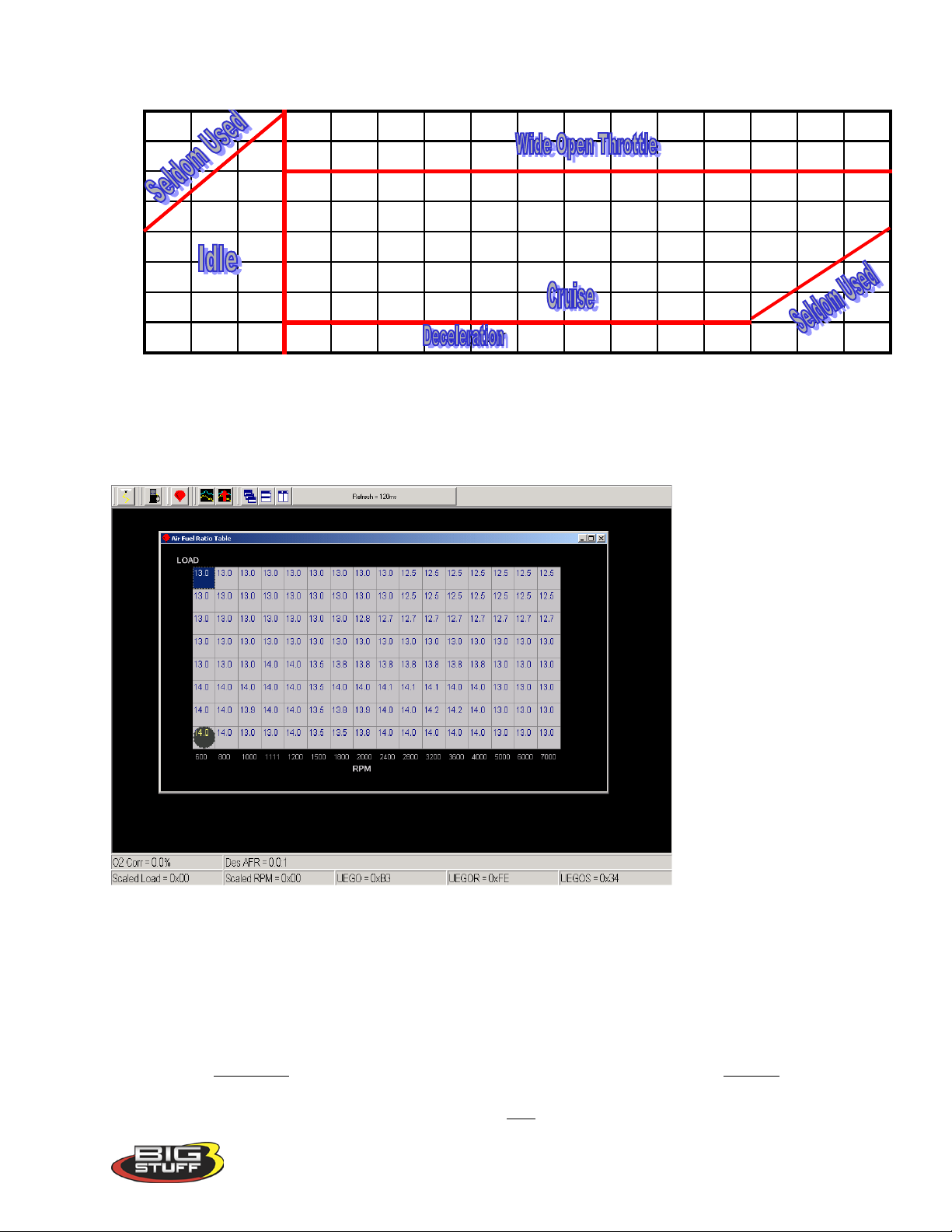
BigStuff3 Pro SEFI System (LS1)
Turbocharged Engine (30 PSI)
13.1 13.1 13.1 11.5 11.5 11.5 11.5 11.5 11.5 11.5 11.5 11.5 11.5 11.5 11.5 11.5
13.5 13.5 13.5 11.75 11.75 11.75 11.75 11.75 11.75 11.75 11.75 11.75 11.75 11.75 11.75 11.75
14 14 14 12 12 12 12 12 12 12 12 12 12 12 12 12
14.5 14.5 14.5 12.5 13.5 13.5 13.5 13.5 13.5 13.5 13.5 13.5 13.5 13.5 13.5 13.5
14.5 14.5 14.5 13 13 13 13 13 13 13 13 13 13 13 13 13
LOAD
14.5 14.5 14.5 14.6 14.7 14.7 14.7 14.7 14.7 14.7 14.7 14.7 14.7 14.7 14.7 14.7
14.5 14.5 14.5 14.6 14.7 14.7 14.7 14.7 14.7 14.7 14.7 14.7 14.7 14.7 14.7 14.7
14.5 14.5 14.5 14.7 14.7 14.7 14.7 14.7 14.7 14.7 14.7 14.7 14.7 14.7 14.7 14.7
600 800 1,000 1,150 1,200 1,500 1,800 2,000 2,400 2,800 3,200 3,600 4,000 5,000 6,000 7,000
RPM
26. Positive 02 Correction
The air fuel ratio table above allows the user to specify desired air/fuel ratios for 128 speed &
load combinations. The positive and negative O2 correction tables below allow the user to
specify how much fuel the O2 Correction will be allowed to add or subtract to achieve the user
defined air/fuel ratio.
The amount added or subtracted is limited by the positive and negative O2 Correction tables.
The eight (8) horizontal input cells in the tables below correspond to the eight (8) vertical “Load”
rows in the Air/Fuel Ratio Table. The input values in the tables below add or subtract fuel, as a
percentage, for each cell in the entire engine “Load” row. The cell all the way to the left
Version 1.0 51
Page 53
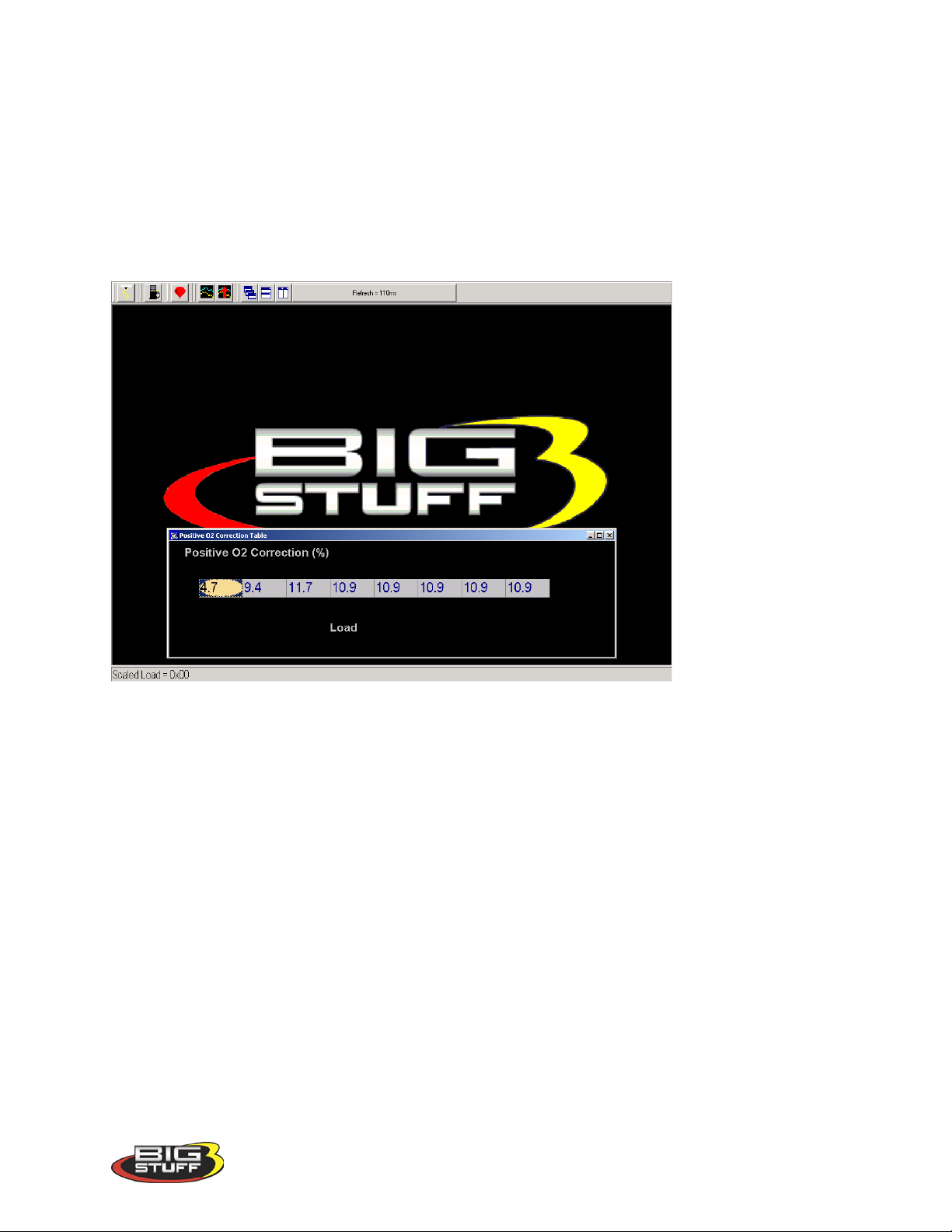
BigStuff3 Pro SEFI System (LS1)
corresponds to the bottom row in the air/fuel ratio table and the cell all the way to the right
corresponds to the top row of the air/fuel ratio table.
The user input values in the Positive O2 Correction table need to be positive numbers and the
input values for the Negative O2 Correction table need to be negative numbers as shown in each
table.
To make changes to the values in these tables, use the left or right arrow keys to move the cursor
to the cell to be changed. Input the desired value and hit “Enter”.
27. Negative 02 Correction
This table is configured and operates in the same way as the table above. The difference being
that this table limits the amount of Negative O2 Correction.
Version 1.0 52
Page 54
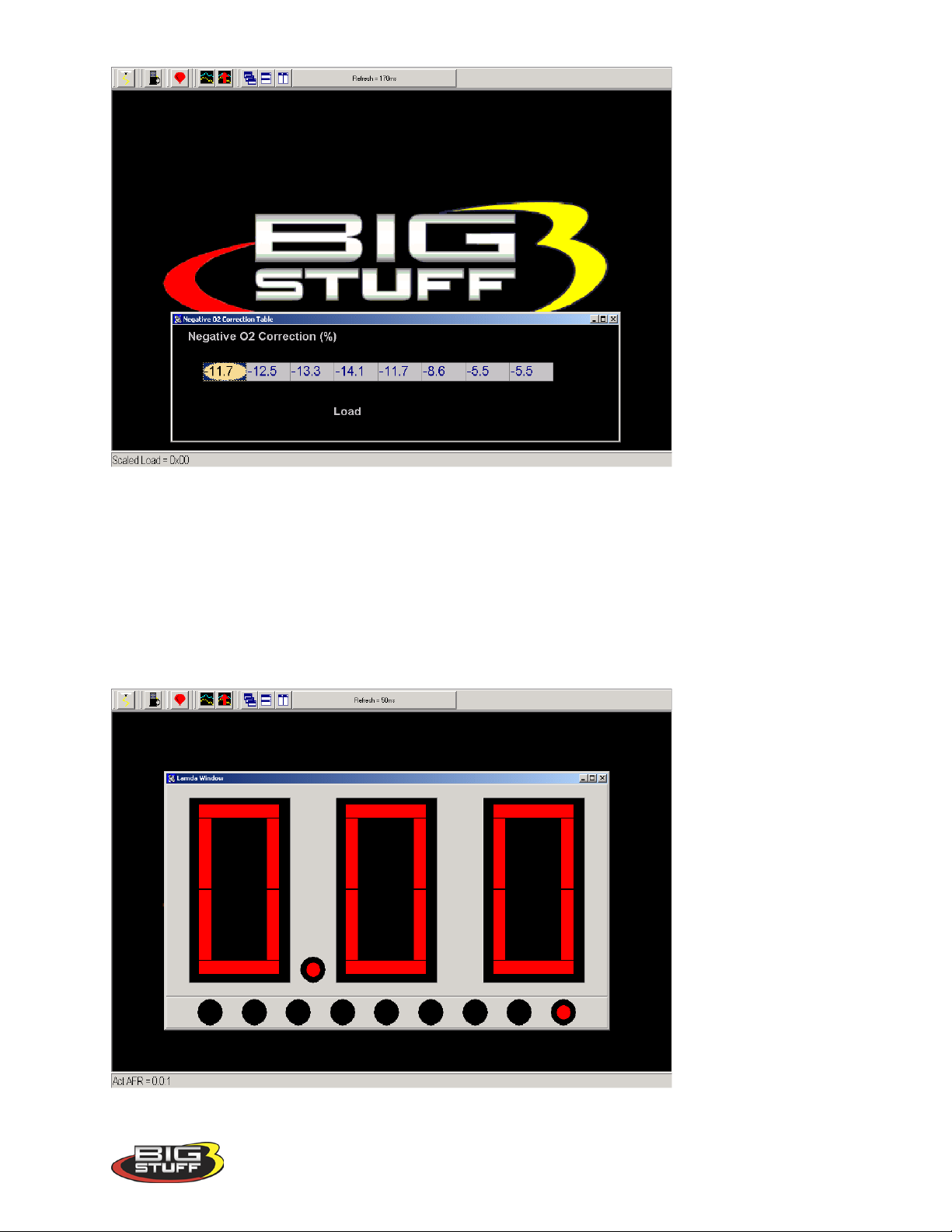
BigStuff3 Pro SEFI System (LS1)
28. View Lambda (F2 – “Quick Key”)
The View Lambda allows the user to view the current Lambda status in a large LED-like format.
The window can be expanded or contracted by locating the mouse cursor at the edge of the
window. The cursor will change shape from an arrow with one (1) point, two an arrow with
points on both ends. When the cursor is in the two-point mode, hold the left mouse button down
and pull the edge of the window in or out to expand or contract the window.
Version 1.0 53
Page 55

BigStuff3 Pro SEFI System (LS1)
29. AFR Parameters (F11 – “Quick Key”)
The Air/Fuel Ratio (AFR) Parameters table allows the user to configure control parameters
associated with closed loop fuel control, using the WBO2 sensor.
The following paragraphs will describe the function of each control parameter.
RPM On & RPM Off Inputs
• RPM On – Defines the RPM the engine needs to exceed before the ECU will allow the
system to go into closed loop fuel control using the O2 sensor.
• RPM Off – Defines the RPM the engine needs to fall below before the ECU will not
allow the system to operate in closed loop fuel control. The RPM Off value needs to be at
least 100 RPM less then the RPM On value.
Max Step and Gain (for the Oxygen Sensor) Inputs
• Maximum Step – Defines the aggressiveness (number of steps) of the O2 sensor when it
updates the O2 correction factor. The step sizes can go from 1% to 12%. For example, if
the O2 sensor needs to make a 15% correction and the Step Gain is set at one (1) the O2
correction loop will go through 15 iterative steps to close the O2 correction gap. If the
Step Gain is set to 12, the sensor will go through only a few steps to close the O2
correction gap.
• Gain % - Gain can range from 1% to 50%. The gain function subtracts the desired air
fuel ratio from the actual air fuel ratio then multiplies the difference by the user defined
gain % and affects the closed loop response.
Hot & Cold Delay Inputs –
• Hot Delay - This input (in seconds) is the time the ECU waits before allowing the system
to go into closed loop fuel control when the engine coolant is above 60
• Cold Delay - This input (in seconds) is the time the ECU waits before allowing the
system to go into closed loop fuel control when the engine is below 60
The Minimum Coolant Temperature threshold described below also affects the Hot and Cold
Delay parameters.
Minimum Coolant Temperature
The minimum coolant temperature input is the temperature threshold the engine coolant needs to
exceed before the ECU will let the system go into closed loop control.
To make changes to the values in these tables, use the left or right arrow keys to move the cursor
to the cell to be changed. Input the desired value and click on “OK” at the bottom of the table.
o
o
F.
F.
Version 1.0 54
Page 56
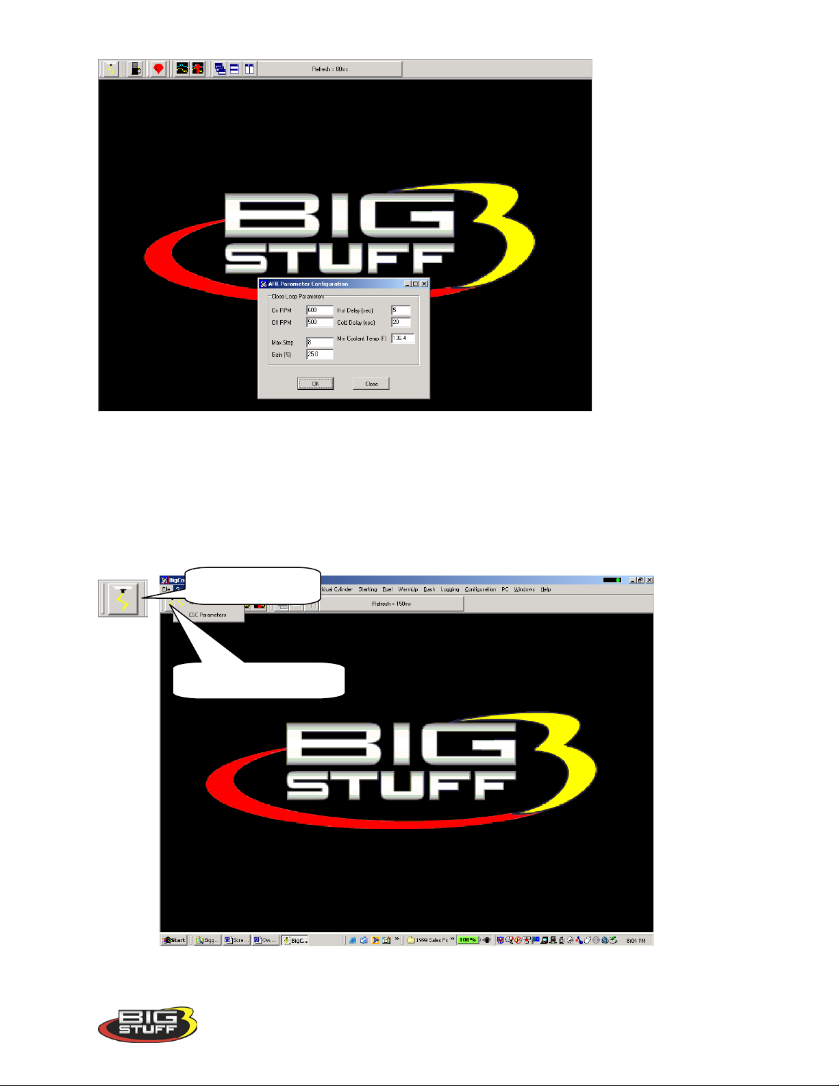
BigStuff3 Pro SEFI System (LS1)
30. SPARK (F4 – “Quick Key”)
There are several ways to access the base Spark table. The quickest methods are to hit the F4
“Quick Key” or left mouse click on the Spark Table icon, accessible from the main BigComm
Screen. The Main Tool Bar can also be used to access the Spark table. From the Main
BigComm software screen tool bar left click on Spark and the drop down screen will open.
Spark Table Icon
Spark table short cut icon
Version 1.0 55
Page 57
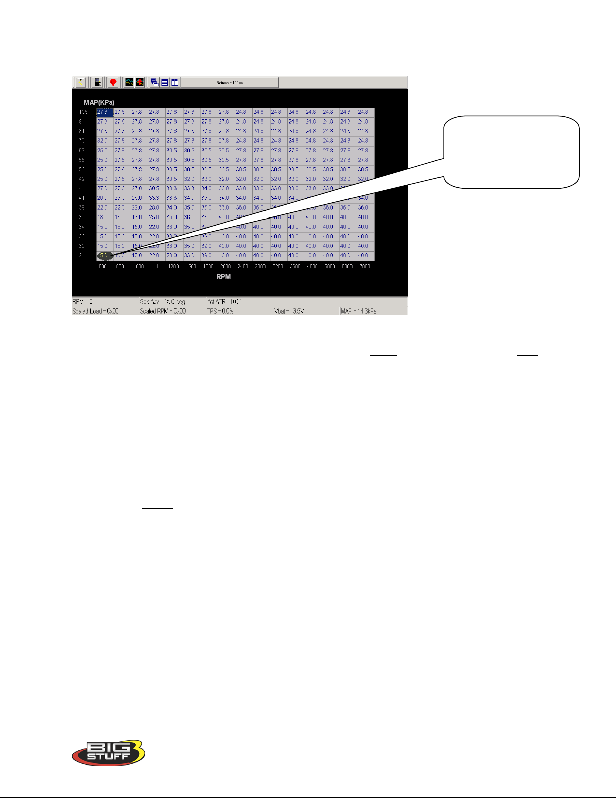
BigStuff3 Pro SEFI System (LS1)
The ellipse will move
31. Spark Table
throughout the Spark table
relative to the current RPM
& Load “operating point”
The Spark table uses actual timing values in each of the 256 cells in the table. The Spark table
allows the user to input Spark values for sixteen- (16) engine speed (RPM) and sixteen (16) load
(MAP or TPS) combinations. The X-axis represents engine RPM and allows for 16 inputs and
the Y-axis represents engine load and allows for sixteen (16) inputs as well. The X and Y-axes
are configurable. For information on how to configure the X and Y-axes see
While the engine is running, a “real-time Ellipse” will move throughout the Spark table relative
to the current RPM & Load “operating point”. Use it as a point of reference to help calibrate the
Spark table.
To change a cell value in the Spark table, move the cursor using the PC’s mouse or the arrow
keys to the cell to be changed. Click on the cell and type a desired Spark value (from to 15.0 to
63.8) and hit “Enter”
to save the change.
To make changes to multiple cells simultaneously, left mouse click and drag the cursor across
the cell range to be changed. Release the left mouse button and a secondary drop down screen
will appear outlining three potential “cell fill” options.
Load_vs_RPM
Version 1.0 56
Page 58
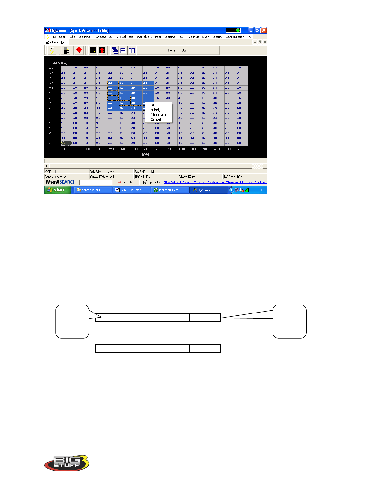
BigStuff3 Pro SEFI System (LS1)
Cell Values Selected in a Row
30.5 27.8 27.8 27.8
Interpolated Result from Cell Values Selected Above
30.5 29.5 28.5 27.8
Cell
Cell
• Fill – Choosing “Fill” will open a secondary drop down- screen which allows the selected
cells to be changed to the value inputted into the window.
• Multiply – Choosing “Multiply” will open a secondary drop down-screen which allows
the values of the selected cells to be changed by the ” Multiply” value inputted into the
window. For example, if the values in the cells selected are 13 and the inputted
“Multiply” value was 80, the new cell values would be 10.4.
• Interpolate – If a series of cells in the same row are selected and the “Interpolate” “cell-
fill” option is selected the ECU will use the value in the cell all the way to the left and the
cell value all the way to the right and interpolate the numbers in between so that the
values are linear.
value to
the left
If a series of cells in the same column are selected and the “Interpolate” “cell-fill” option is
selected the ECU will use the value in the cell all the way at the bottom and the cell value all the
way at the top and interpolate the numbers in between so that the values are linear.
Version 1.0 57
value to
the left
Page 59

BigStuff3 Pro SEFI System (LS1)
Cell Values Selected in a Column
27.8
30.53233
Interpolated Result from Cell Values Selected Above
27.8
29.5
31.3
33
Range of Cell Values Selected
27 30.5 33.3 33.3
26 33.3 33.3 34
22 28 34 35
18 25 35 36
15 22 33 35
Interpolated Result from Range of Cell Values Selected Above
27 29 31 33.3
24 27 30.3 33.5
21 25.3 29.8 34
18 23.5 29 34.5
15 21.5 28.3 35
If a range of cells (multiple rows and columns) are selected and the “Interpolate” “cell-fill”
option is selected the ECU will use the value in the cells at the bottom left and top left corners,
bottom left and bottom right corners and the bottom left and top right corners of the entire range
and interpolate the numbers in between so that the values are linear.
• Cancel – Hit cancel to disregard making any changes.
The illustration below shows the areas of the Spark map that the ECU accesses under different
driving conditions.
Version 1.0 58
Page 60
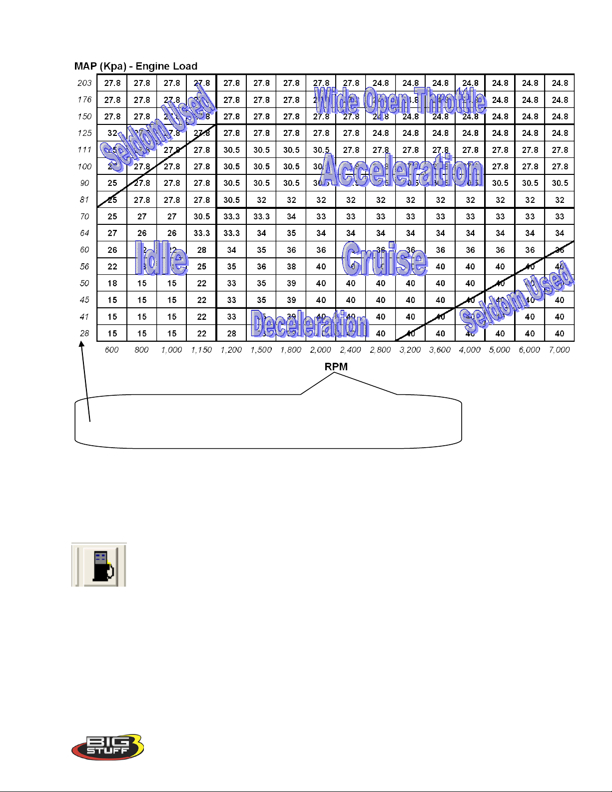
BigStuff3 Pro SEFI System (LS1)
The BigComm software al l ows the user to configure the Load (MAP)
and RPM axes allowing for a larger number of cells (map area) to be
used for the fuel and spark tables.
32. FUEL (F3 – “Quick Key”)
There are several ways to access the base Fuel table. The quickest methods are to hit the F3 key
or left mouse click on the Fuel Table icon, accessible from the main BigComm Screen.
The Main Tool Bar can also be used to access the “Fuel” table. From the Main BigComm
software screen tool bar left click on Fuel and the drop down screen will open.
Version 1.0 59
Page 61
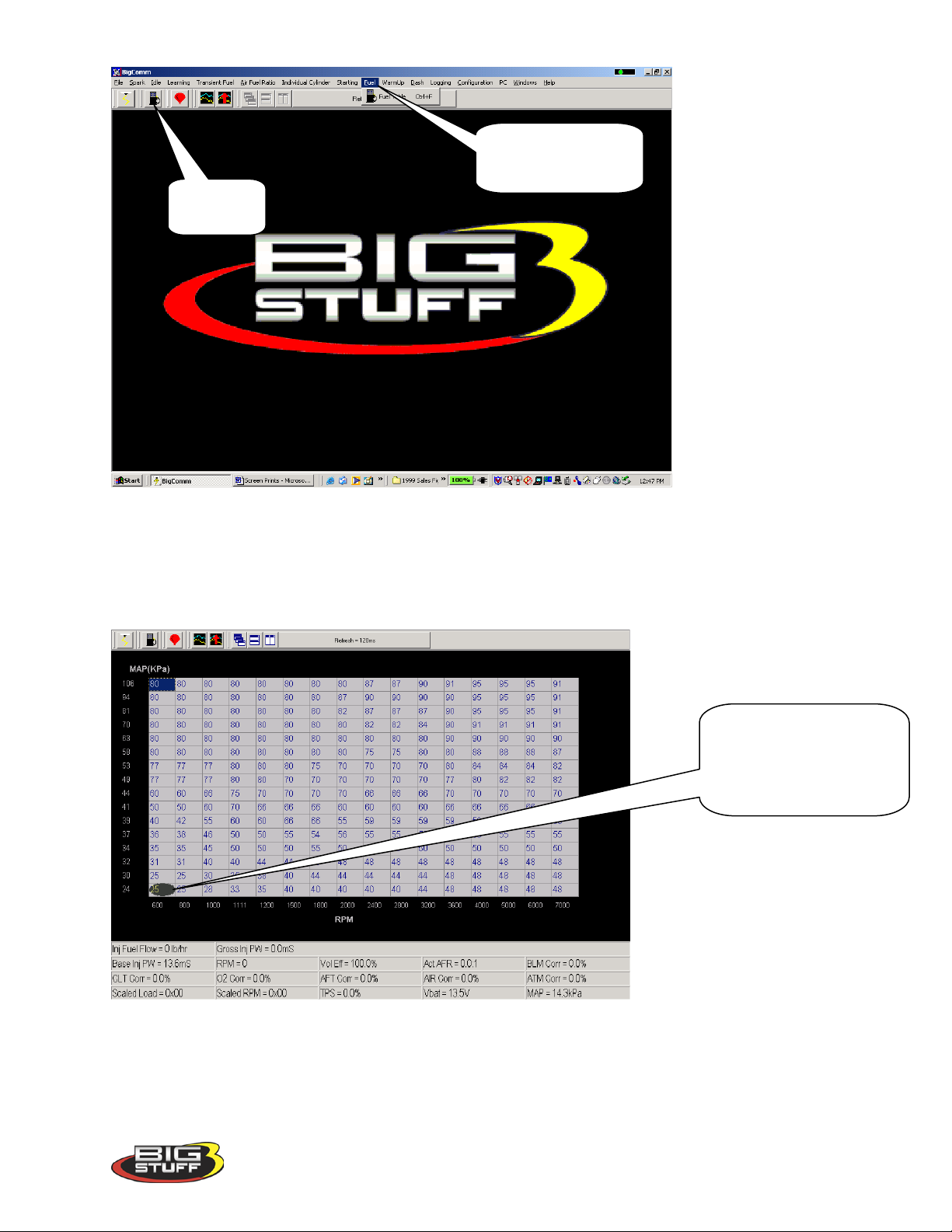
BigStuff3 Pro SEFI System (LS1)
Fuel Table
Fuel table drop down
the Main Tool Bar
The ellipse will move
screen accessed from
Icon
Using the PC’s mouse, keep the left mouse button depressed and slide the mouse pointer down
until “Fuel Table” is highlighted. Release the left mouse button. The screen below will open.
33. Fuel Table
throughout the Fuel table
relative to the current RPM
& Load “operating point”
Note: In most cases, the ECU shipped with your system will come pre-configured with a table
that will closely match your engine configuration.
Version 1.0 60
Page 62
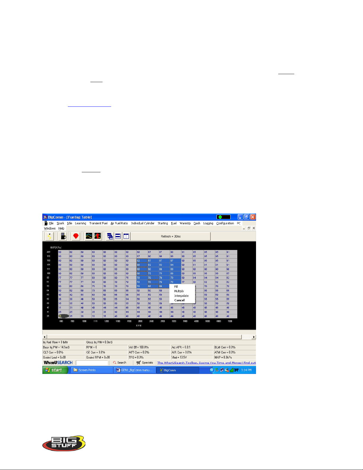
BigStuff3 Pro SEFI System (LS1)
The Fuel table uses Volumetric Efficiency (VE) values in each of the 256 cells in the table.
Volumetric Efficiency is the measure for how efficient the engine is operating at a given engine
speed and load combination. The efficiency of the engine is nearly perfect at a value of 100.
Volumetric Efficiency (VE) is highest at peak torque.
The Fuel table allows the user to input desired (VE) values for sixteen (16) engine speed (RPM)
and sixteen (16) load (MAP or TPS) combinations. The X-axis represents engine RPM and
allows for 16 inputs and the Y-axis represents engine load and allows for sixteen (16) inputs as
well. The X and Y-axes are configurable. For information on how to configure the X and Yaxes see Load_vs_RPM
While the engine is running, a “real-time Ellipse” will move throughout the Fuel table relative to
the current RPM & Load “operating point”. Use it as a point of reference to help calibrate the
Fuel table.
To change a VE cell value in the Fuel table, move the cursor using the PC’s mouse or the arrow
keys to the cell to be changed. Click on the cell and type a desired VE value (from to 15.0 to
200) and hit “Enter” to save the change.
To make changes to multiple cells simultaneously, left mouse click and drag the cursor across
the cell range to be changed. Release the left mouse button and a secondary drop down screen
will appear outlining three potential “cell fill” options
• Fill – Choosing “Fill” will open a secondary drop down- screen which allows the selected
cells to be changed to the value inputted into the window.
• Multiply – Choosing “Multiply” will open a secondary drop down-screen which allows
the values of the selected cells to be changed by the ” Multiply” value inputted into the
window. For example, if the values in the cells selected are 13 and the inputted
“Multiply” value was 80%, the new cell values would be 10.4.
Version 1.0 61
Page 63
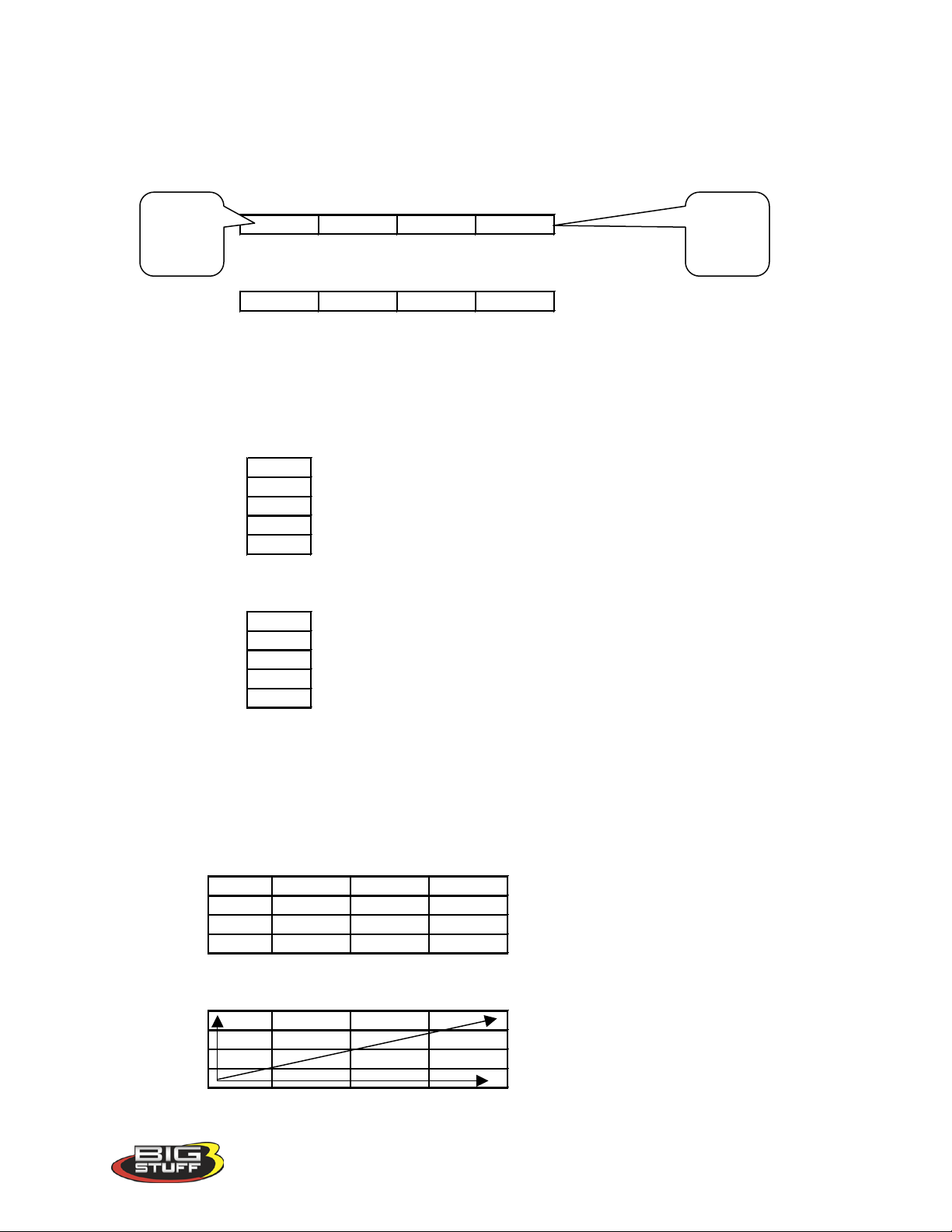
BigStuff3 Pro SEFI System (LS1)
Cell Values Selected in a Row
70 70 70 80
Interpolated Result from Cell Values Selected Above
70 73 77 80
Cell Values Selected in a Column
9080707070
Interpolated Result from Cell Values Selected Above
9085807570
Range of Cell Values Selected
80 80 80 80
80 80 80 80
80 79 77 80
77 77 75 80
Interpolated Result from Range of Cell Values Selected Above
80 80 80 80
79 80 80 80
78 79 80 80
77 78 79 80
Cell
Cell
• Interpolate – If a series of cells in the same row are selected and the “Interpolate” “cell-
fill” option is selected the ECU will use the value in the cell all the way to the left and the
cell value all the way to the right and interpolate the numbers in between so that the
values are linear.
value to
the left
value to
the left
If a series of cells in the same column are selected and the “Interpolate” “cell-fill” option is
selected the ECU will use the value in the cell all the way at the bottom and the cell value all the
way at the top and interpolate the numbers in between so that the values are linear.
If a range of cells (multiple rows and columns) are selected and the “Interpolate” “cell-fill”
option is selected the ECU will use the value in the cells at the bottom left and top left corners,
bottom left and bottom right corners and the bottom left and top right corners of the entire range
and interpolate the numbers in between so that the values are linear.
• Cancel – Hit cancel to disregard making any changes.
Version 1.0 62
Page 64
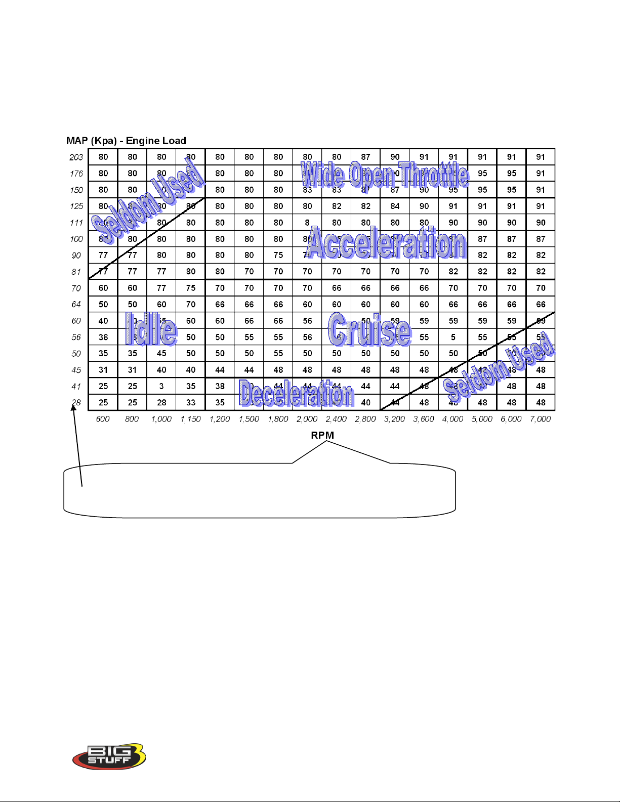
BigStuff3 Pro SEFI System (LS1)
The BigComm software allows the user to configure the Load (MAP)
The illustration below shows the areas of the base fuel map that the ECU accesses under
different driving conditions.
Hint: Use the 02% Correction feedback in the Dash to help calibrate the Fuel table VE values.
and RPM axes allowing for a larger number of cells (map area) to be
used for the fuel and spark tables.
Note: Be sure the ECU is properly configured and the Base Fuel and S park Tables are calibrated before configuring and calibrating any of the following engine operating parameters.
34. STARTING
The “Starting” drop-down selections allow the user to calibrate parameters associated with
starting (cranking) and running the engine for a short period of time (temperature dependent)
after the engine is initially started.
To configure engine starting fuel, go to Starting on the Tool Bar. Left click on “Starting” and a
drop down screen will open. Keep the left mouse button depressed and slide the mouse pointer
down until the desired “Starting” fuel drop down is highlighted.
Version 1.0 63
Page 65
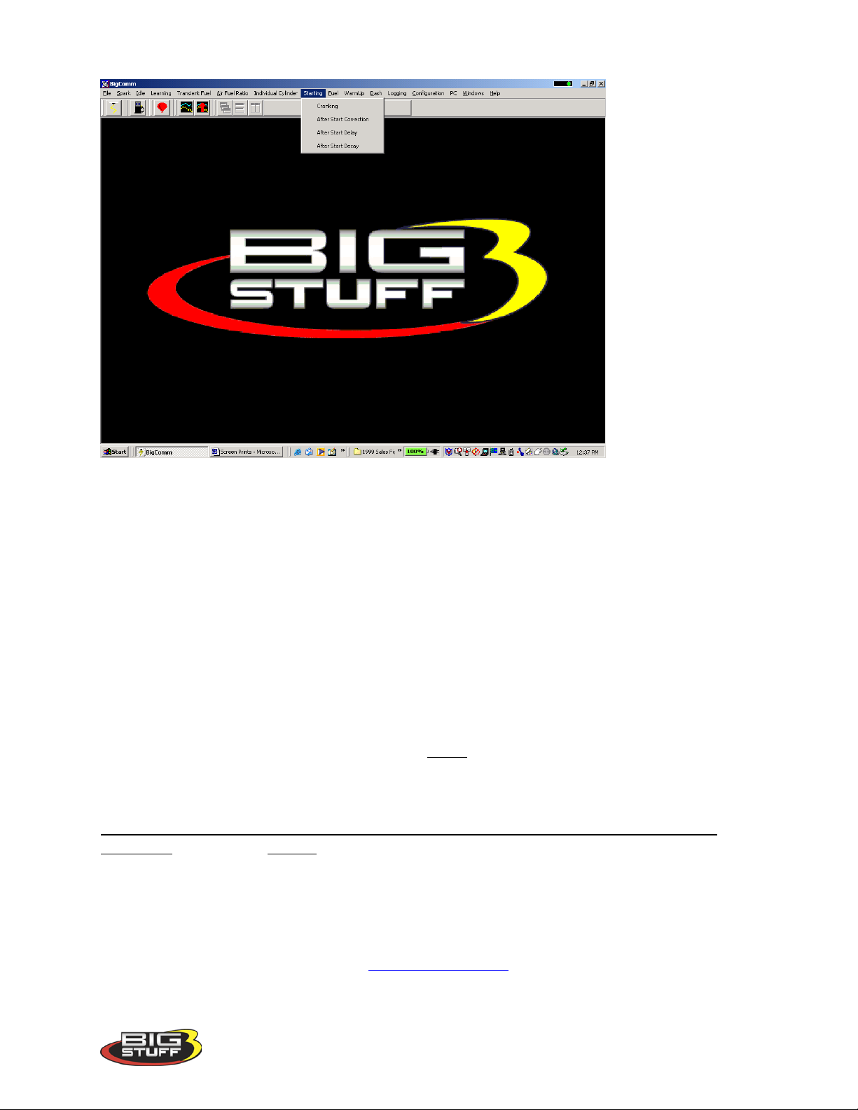
BigStuff3 Pro SEFI System (LS1)
The sequence of events the ECU steps through during an engine “start” are defined, in order, in the next four sections as follows:
• Cranking
• After Start Delay
• After Start Correction (adding fuel)
• After Start Decay
35. Cranking (F1 – “Quick Key”)
The inputs in this table are only used by the ECU when the engine is in the cranking mode (<
400 RPM).
The Cranking table allows the user to input the actual pulse width the injectors will operate at
during engine cranking. The pulse width required is a function of the engine coolant
temperature. The colder the engine the larger the pulse width required.
If the throttle needs to be opened to start the engine during Cranking, the ECU is adding to
much fuel. Therefore, a smaller injector pulse width needs to be entered into the input cell
relative to the engine coolant temperature. Make sure pulse width modifications are inputted
into the correct input cells. Entering a smaller pulse width into the cell representing an engine
coolant temperature of 144o will not help start the engine when the temperature is 55
Note: If the throttle is opened to position greater than what was set in the Clear Flood TPS %
setting, the ECU will not add fuel. See
Clear_Flood_Setting for more details.
o
.
Version 1.0 64
Page 66
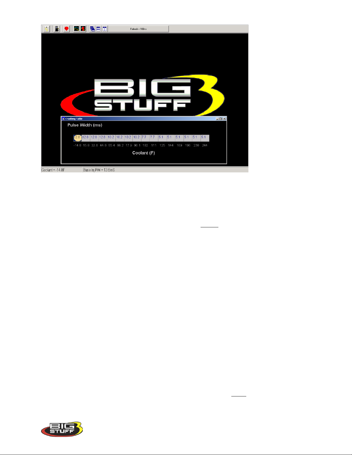
BigStuff3 Pro SEFI System (LS1)
While the engine is cranking, a “real-time Ellipse” will move within the Cranking table relative
to the current engine coolant temperature “operating point”. Use it as a point of reference to help
calibrate the Cranking table.
To change a value in the Cranking table, move the cursor using the PC’s mouse or arrow keys
to the cell to be changed. Input the desired value and hit “Enter” to save the change.
Once the engine starts (the ECU will detect the rapid change in engine speed) the ECU will
ignore the Cranking table and begin using inputs from the After Start Delay (see section 36).
36. After Start Delay
Once the ECU detects the engine has started, it uses the vehicle coolant temperature sensor and
inputs from the After Start Delay table to decide when to introduce the After Start Correction
Fuel. The ECU begins counting the crankshaft interrupts. When the ECU counts off the number
of interrupts defined in the After Start Delay table, for the current engine operating temperature,
the ECU adds the After Start Correction Fuel. The delay mentioned here is very, very short.
The table below shows 9 interrupts were used at –14o and 16 interrupts at 230o. One can
appreciate how quickly nine (9) or sixteen (16) crankshaft interrupts occur at an engine speed of
800 RPM.
While the engine is running, a “real-time Ellipse” will move within the After Start Delay table
relative to the current engine coolant temperature “operating point”. Use it as a point of
reference to help calibrate the After Start Delay table.
To change a value in the After Start Delay table, move the cursor using the PC’s mouse or
arrow keys to the cell to be changed. Input the desired value and hit Enter to save the change.
Version 1.0 65
Page 67
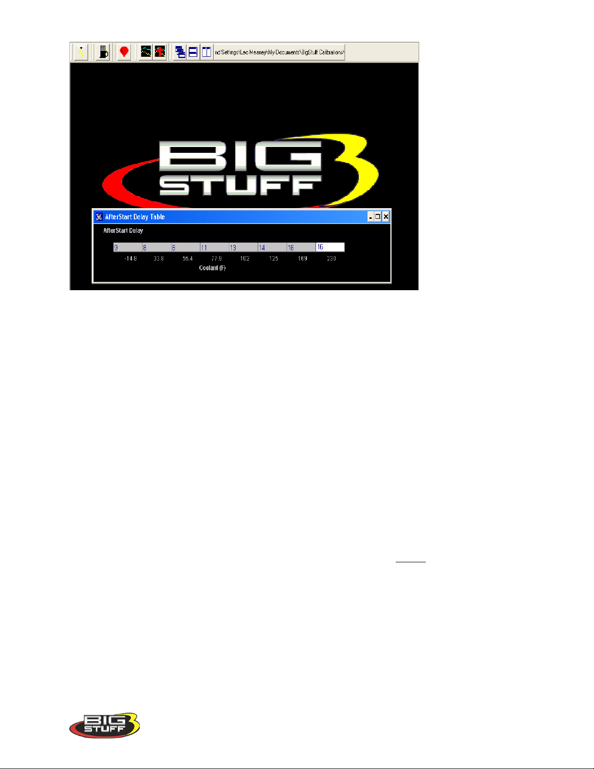
BigStuff3 Pro SEFI System (LS1)
37. After Start Correction
As outlined above, the ECU delays the introduction of After Start Correction fuel once the
engine starts.
The table below allows the user to define the amount of After Start Correction fuel to be added
as a function of coolant temperature. The After Start Correction fuel is added synchronously
as a percent (%) of the base pulse width (defined in the Fuel table). As you will notice in the
table, the percent (%) of fuel added is greater at the two temperature extremes. The largest
amount of fuel is needed when the engine is coldest. A larger amount of fuel is also added when
the engine is hot versus the mid range temperatures, to release any vaporized fuel that may have
“boiled” in the fuel rail(s) during a hot soak.
While the engine is running, a “real-time Ellipse” will move within the After Start Correction
table relative to the current engine coolant temperature “operating point”. Use it as a point of
reference to help calibrate the After Start Correction table.
To change a value in the After Start Correction table, move the cursor using the PC’s mouse or
arrow keys to the cell to be changed. Input the desired value and hit “Enter” to save the change.
Version 1.0 66
Page 68
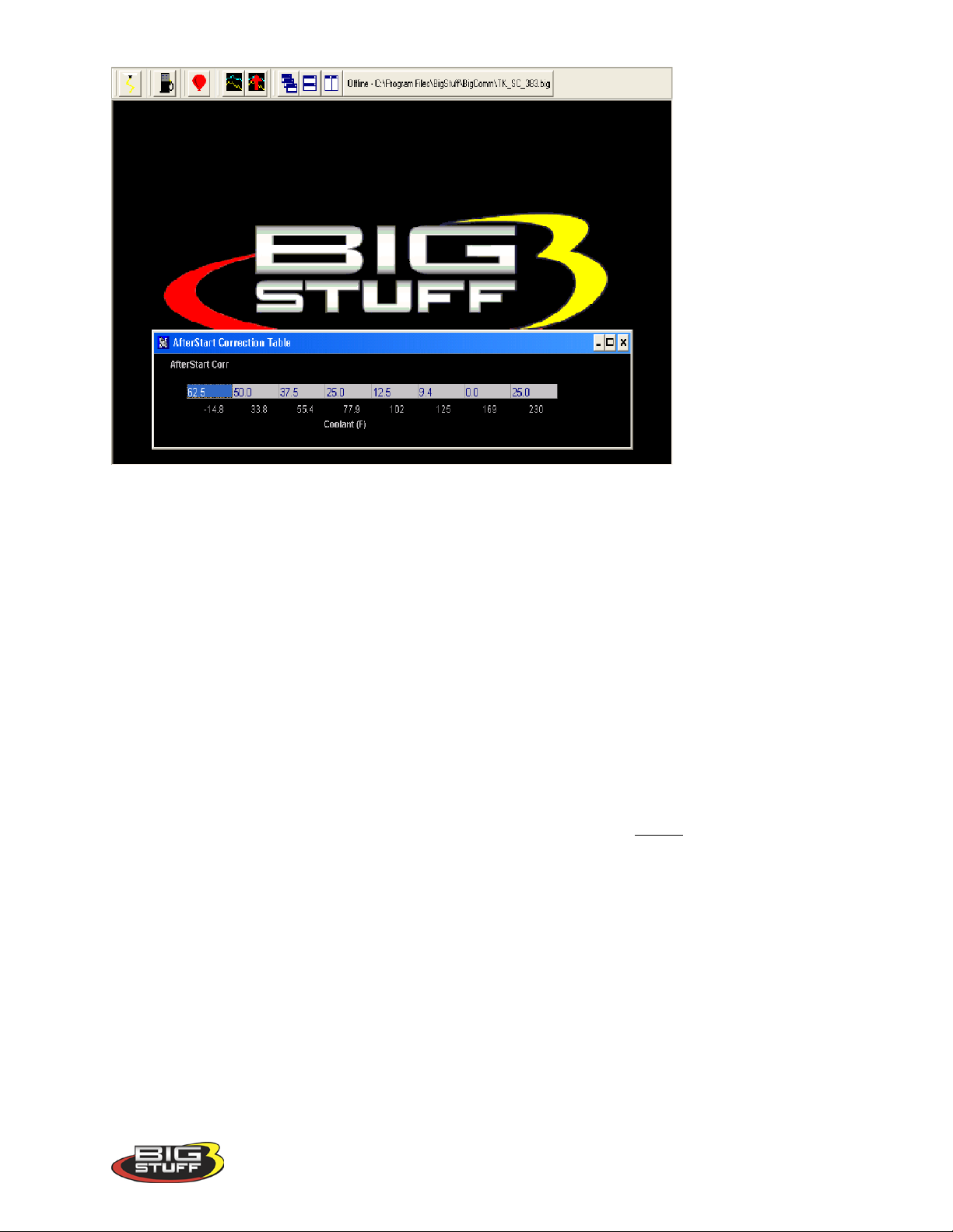
BigStuff3 Pro SEFI System (LS1)
38. After Start Decay
The After Start Correction fuel being added by the ECU during an engine starting routine is
only required for a very short period of time. The ECU pulls the fuel back out, or decays it, as a
function of crankshaft interrupts and coolant temperature. The ECU decays the After Start
Correction Fuel over the number of interrupts, depending on the temperature the engine is
currently operating at, defined in the After Start Decay table. The decay period mentioned here
is very, very short. The table below shows 8 interrupts were used at –14o and 22 interrupts at
230o.
While the engine is running, a “real-time Ellipse” will move within the After Start Decay table
relative to the current engine coolant temperature “operating point”. Use it as a point of
reference to help calibrate the After Start Decay table.
To change a value in the After Start Decay table, move the cursor using the PC’s mouse or
arrow keys to the cell to be changed. Input the desired value and hit “Enter” to save the change.
Version 1.0 67
Page 69
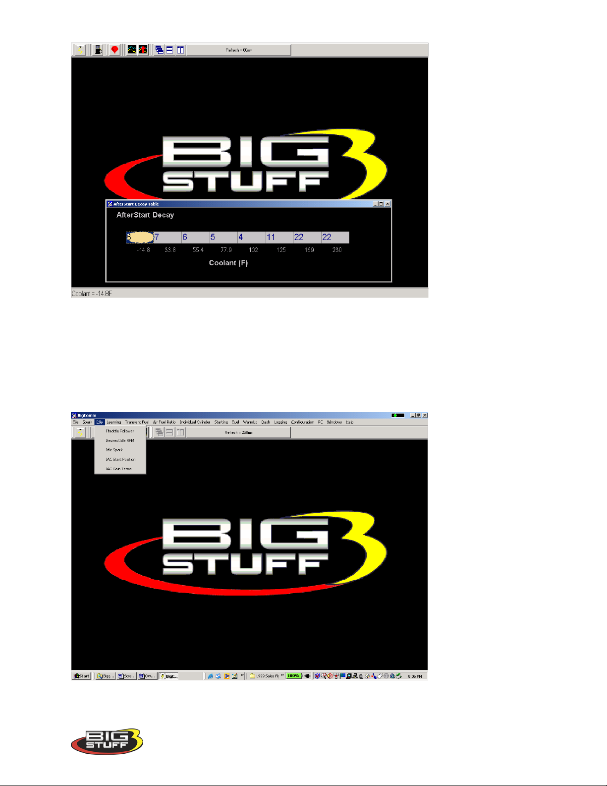
BigStuff3 Pro SEFI System (LS1)
39. Idle
The “Idle” drop down offers the user five tables to calibrate the engine idle quality. Each input
table will be described in the paragraphs below. To get to the Idle drop down screen, go to the
main Tool Bar and left click on Idle and the screen below will appear. Hold the left mouse down
and drag it to the desired input screen and release the mouse button.
Version 1.0 68
Page 70
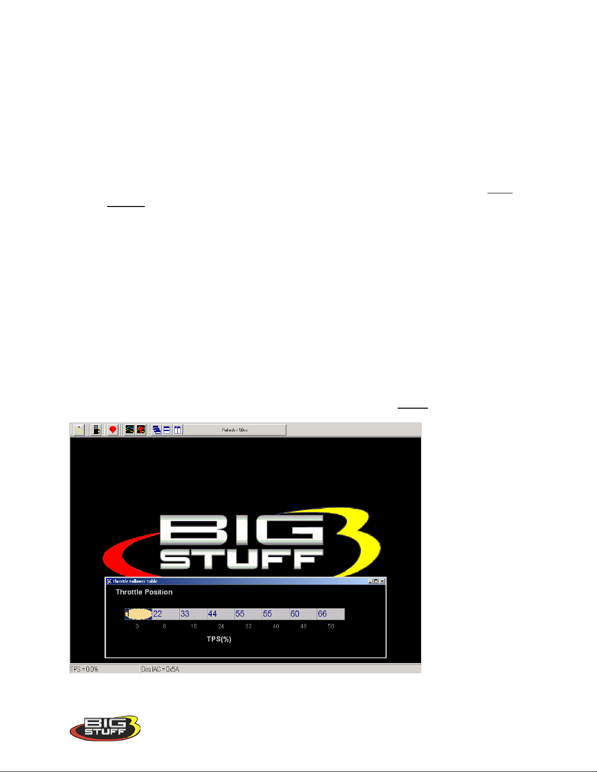
BigStuff3 Pro SEFI System (LS1)
40. Throttle Follower
Throttle bodies used with electronic fuel injection systems have an air by-pass channel molded or
machined into the valve body to allow air to be bypassed around the throttle blades when they
are fully closed. The air entering the engine through the bypass channel is used to control the
engine idle speed. The amount of air needed to maintain a desired engine speed varies
depending on engine coolant temperature, camshaft overlap, etc. The Idle Airspeed Control
(IAC) motor (and plunger) control the amount of air allowed to be bypassed around the throttle
blades.
The “Throttle Follower” table allows the user to set a relationship between throttle blade angle
and the position of the IAC metering valve (plunger). This is required to keep the engine from
stalling when the throttle position changes from some percent (%) open to fully closed very
quickly.
The fixed values along the bottom of the table below represent the percent (%) throttle position
which increase in increments of eight (8) percent. The input values above the fixed numbers are
used by the ECU to position the IAC metering valve (plunger), inside the bypass channel. The
position of the metering valve (plunger) will vary depending on throttle position. The default
values, configured with the system as shipped, will work with a majority of engine applications.
While the engine is running, a “real-time Ellipse” will move within the Throttle Follower
Table relative to the current TPS (%) “operating point”. Use it as a point of reference to help
calibrate the Throt tl e Fo ll ow er table.
To change a value in the Throttle Follower table, move the cursor using the PC’s mouse or
arrow keys to the cell to be changed. Input the desired value and hit “Enter” to save the change.
Version 1.0 69
Page 71
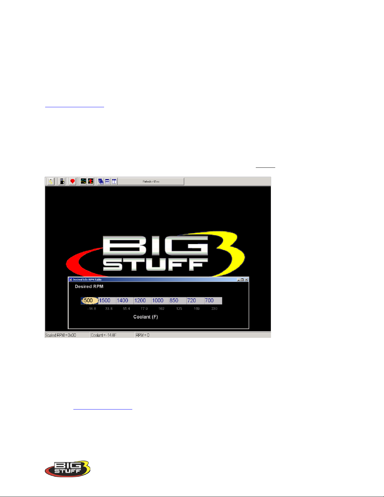
BigStuff3 Pro SEFI System (LS1)
41. Desired Idle RPM
The Desired Idle Rpm table allows the user to set the desired engine RPM as a function of
coolant temperature. To configure the table, input the desired engine RPM for the each
temperature shown at the bottom of the table. The ECU controls the idle speed so transitions
between temperature ranges are not noticeable.
Note: The TPS needs to be set properly for this input to function properly. See
TPS_Configuration for further assistance.
While the engine is running, a “real-time Ellipse” will move within the Desired Idle Rpm
Table relative to the current engine coolant temperature “operating point”. Use it as a point of
reference to help calibrate the Desired Idle Rpm table.
To change a value in the Desired Idle Rpm table, move the cursor using the PC’s mouse or
arrow keys to the cell to be changed. Input the desired value and hit “Enter” to save the change.
.
42. Idle Spark
The Idle Spark control function helps maintain idle quality by introducing bi-directional spark
timing as an additional control variable.
Note: This control strategy is only invoked when the throttle position is below the Max TPS for
Idle. See TPS_Configuration!
The fixed values, below the table, are the ECU’s reference points for how many RPM the engine
is operating at above or below the “Desired RPM.” The fixed values define the active control
(RPM) range. The active range is from 256 RPM below the “Desired” RPM to 224 RPM above
the “Desired” RPM.
Version 1.0 70
Page 72
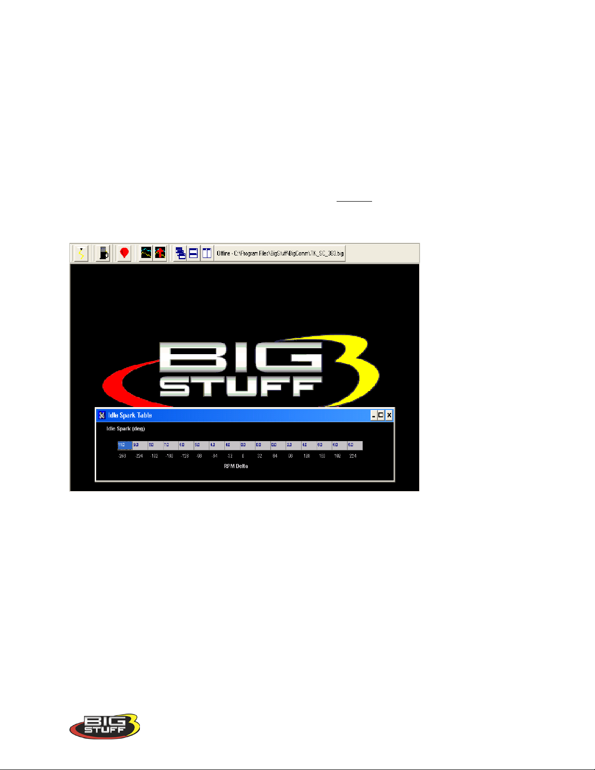
BigStuff3 Pro SEFI System (LS1)
The bi-directional input table allows the user to quickly advance the timing (left side of the input
table) when the RPM begins falling below the “Desired RPM” setting. Once the timing is
advanced it needs to be retarded (right side of the input table) as the engine RPM begins
increasing. The zero point in the table is equal to the user defined, “Desired” RPM.
While the engine is running, a “real-time Ellipse” will move within the Idle Spark table relative
to the current RPM Delta “operating point”. Use it as a point of reference to help calibrate the
Idle Spark table.
To change a value in the Idle Spark table, move the cursor using the PC’s mouse or arrow keys
to the cell to be changed. Input the desired value and hit ”Enter” to save the change.
The values shown in the table below can be used as a baseline.
43. IAC Start Position
A general description of the IAC motor and valve (plunger) was described above in the “Throttle
Follower” paragraph. The IAC motor can be in one (1) of one hundred eighty (180) potential
positions, from fully open to fully closed. Fully closed would represent position number one and
fully open would represent position number 180. The ECU monitors key engine operating
conditions and positions the IAC valve (plunger) accordingly. When the engine is shut off, the
IAC goe s to position number zero and then counts back to position number 90, or half way open,
and stays there. When the engine goes into cranking mode the ECU reads the coolant
temperature and instructs the IAC what position to go to. Based on user defined inputs, the IAC
Start Position Table allows the ECU to position the IAC valve to a predetermined position
while the engine is cranking, so that when the engine starts the idle speed can be quickly reached
and maintained.
Version 1.0 71
Page 73
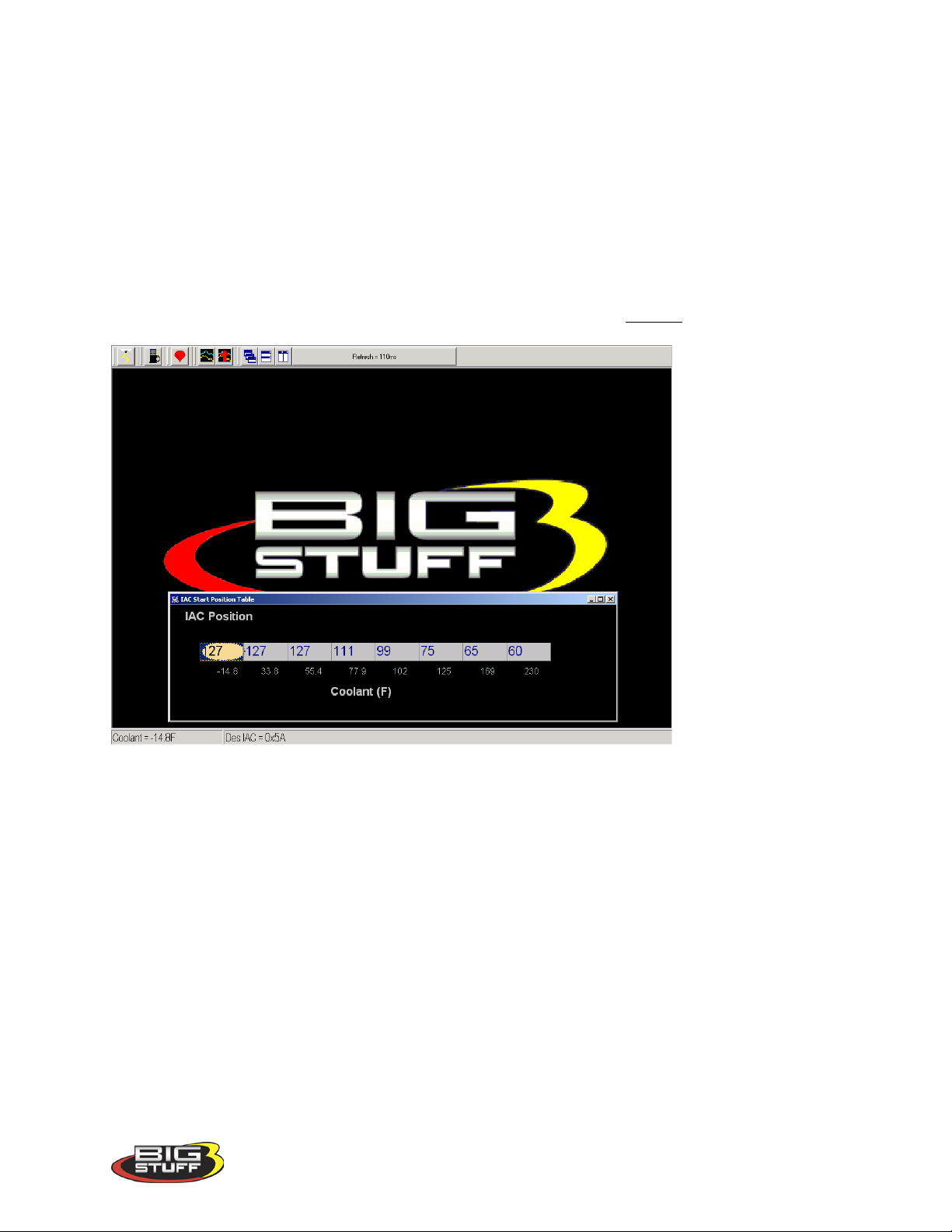
BigStuff3 Pro SEFI System (LS1)
The “position” values shown in the table below can be used as a baseline for most applications.
You can see from the large values in the table that when the coolant temperature is cold, the IAC
seeks a position in the direction of the fully open position (position number 180). As the engine
reaches normal operating temperature, the IAC finds the position that allows the engine to idle at
the user prescribed “Desired” idle speed.
While the engine is running, a “real-time Ellipse” will move within the IAC Start Position table
relative to the current engine Coolant Temperature “operating point”. Use it as a point of
reference to help calibrate the IAC Start Position table.
To change a value in the IAC Start Position table, move the cursor using the PC’s mouse or
arrow keys to the cell to be changed. Input the desired value and hit ”Enter” to save the change.
44. IAC Gain Terms
This input table allows the user to set how quickly the IAC motor moves (in or out) in a given
period of time. Use the default settings that come with the ECU unless it becomes necessary to
control the IAC motor speed. The Proportional Gain setting should be from 4 to 16. The
Derivative Gain should be ¼ to ½ of the Proportional Gain. Enter the desired value in the table
and left mouse click OK to save the information.
Version 1.0 72
Page 74
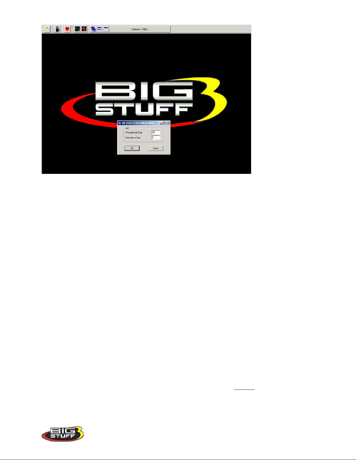
BigStuff3 Pro SEFI System (LS1)
45. Warm Up
Before the engine reaches normal operating temperature, i.e. 180
function of engine coolant temperature and manifold absolute pressure (for speed-density
applications). To calibrate “warm up enrichment” fuel go to the Main Tool bar and highlight
“Warm Up.” Keep the left mouse button depressed and slide the cursor down to select Coolant
Correction or Air Temperature Correction, depending on the table to be accessed.
o
additional fuel is required as a
46. Air Temperature Correction
The inputs from this table are used by the ECU if “Alpha N” was the control algorithm selected
during the Main Configuration set up. If the “Speed Density” the control algorithm was selected,
the ECU ignores inputs from this table.
For Alpha N systems, the ECU uses input from this table for air temperature compensation. The
fixed numbers in the input table represent air temperature from –14.8
the user-defined inputs for each temperature point to add or subtract fuel relative to the base fuel
map values.
While the engine is running, a “real-time Ellipse” will move within the Air Temperature table
relative to the current engine Coolant Temperature “operating point”. Use it as a point of
reference to help calibrate the Air Temperature table.
To change a value in the Air Temperature table, move the cursor using the PC’s mouse or
arrow keys to the cell to be changed. Input the desired value and hit ‘Enter” to save the change.
The input values need to be smaller working from the left to right. As the engine warms up it
needs less Air Temperature correction (added fuel).
o
to 244 o F. The ECU uses
Version 1.0 73
Page 75
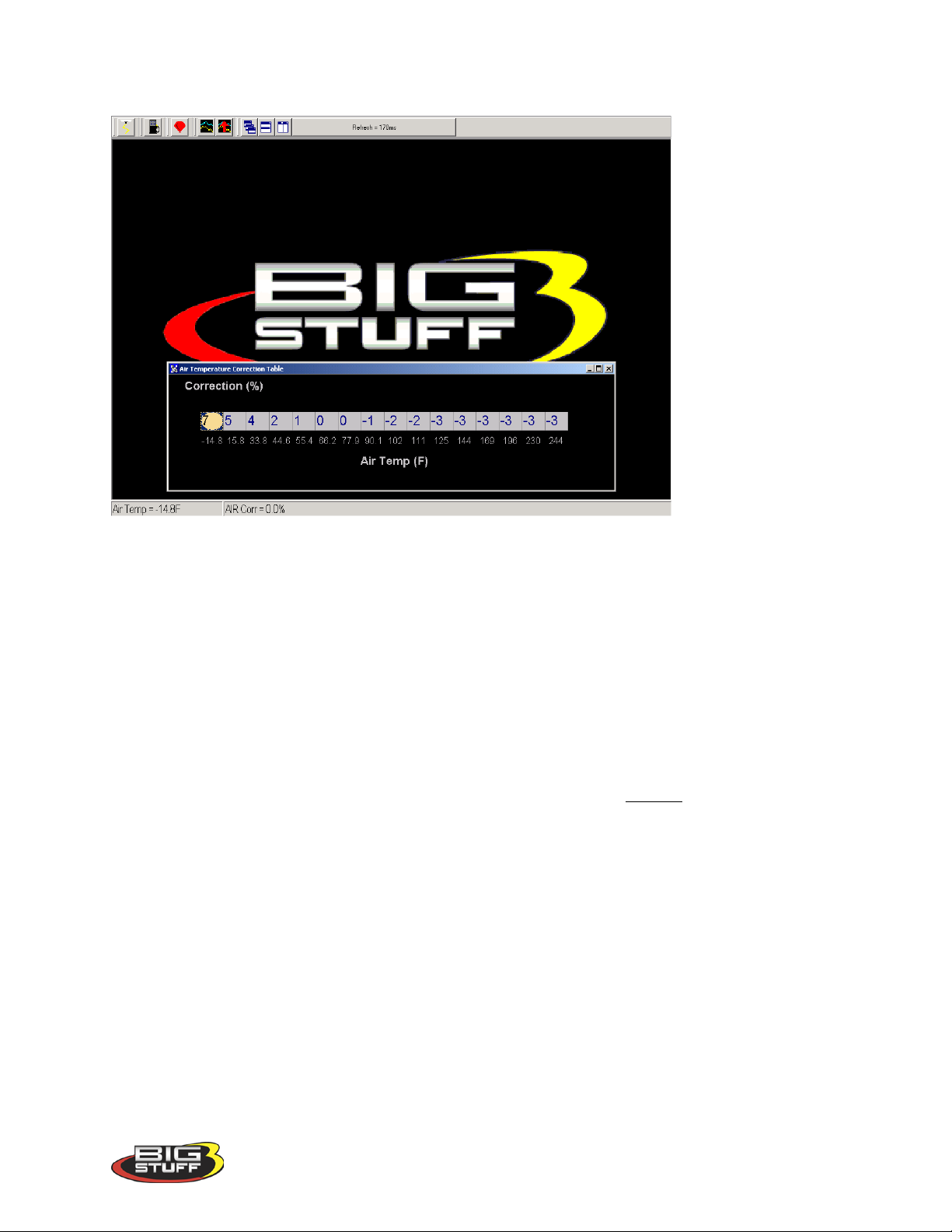
The inputs shown in the table below can be used as a baseline.
BigStuff3 Pro SEFI System (LS1)
47. MAP Vs. Coolant
The GEN3 ECU’s MAP vs. Coolant table offers an improved warm up routine. The table
applies a fuel correction (a % increase or decrease to the base pulse width) as a function of both
Load (MAP) and coolant temperature. The cells in the table represent ninety six (96) different
MAP and coolant temperature combinations.
The same calibration technique should be used with this table as was employed with the base
fuel map. This table should be calibrated after the base fuel map.
To change a value in the MAP vs. Coolant table, move the cursor using the PC’s mouse or
arrow keys to the cell to be changed. Input the desired value and hit “Enter” to save the change.
Version 1.0 74
Page 76
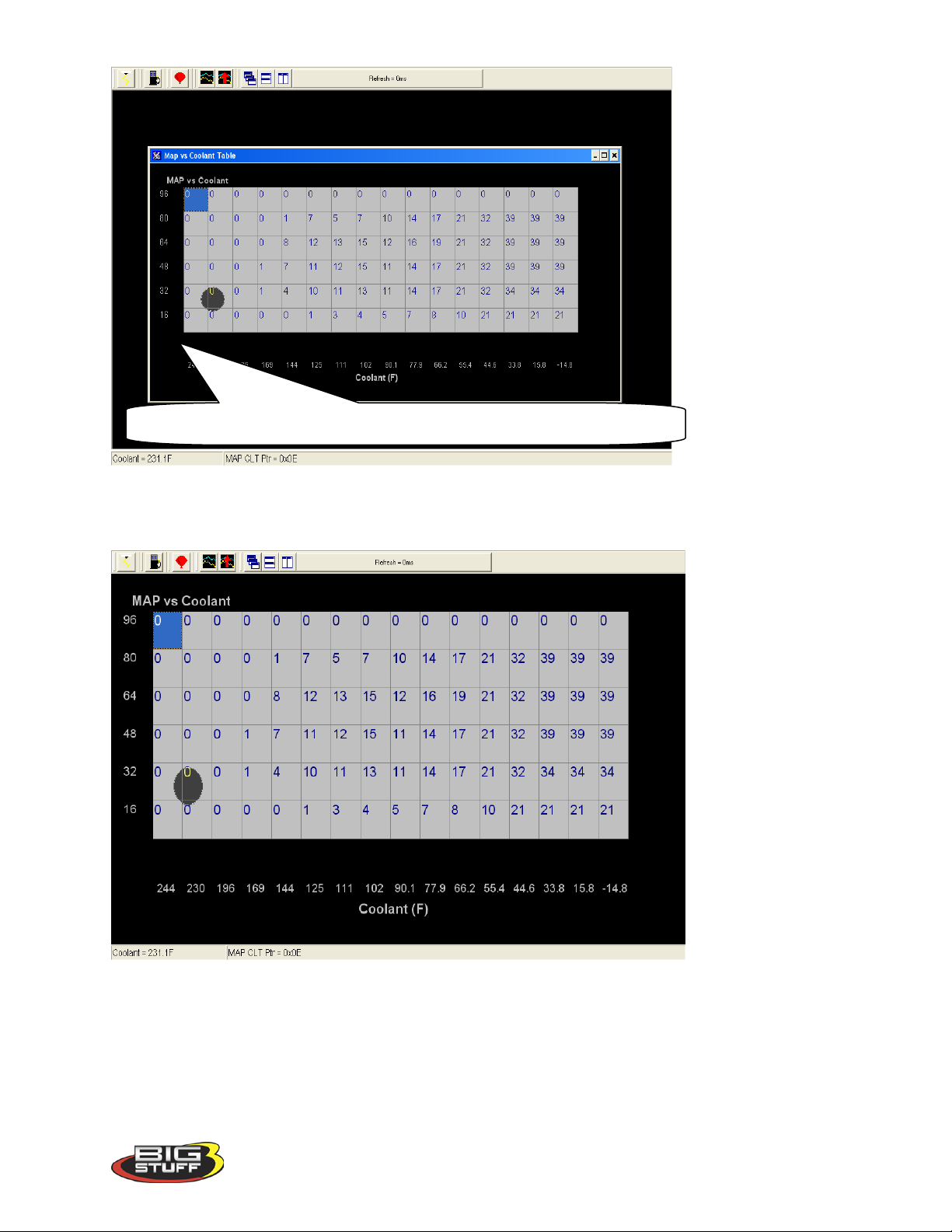
BigStuff3 Pro SEFI System (LS1)
The values in the X & Y axes are factory set and therefore not configurable.
Same screen as above with the window maximized. The values shown in the table below can be
used as baseline.
48. TRANSIENT FUEL
Transient Fuel is the fuel added to the engine during non-steady state conditions as a function of
dTPSdt and dMAPdt. Transient Fuel is applied relative to a rate of throttle change (dTPS) and a
rate of MAP change (dMAP). TPS transient fuel is added asynchronously. Asynchronously
means fuel added between the regularly scheduled injector pulses. MAP transient fuel is added
synchronously to increase or decrease the base fuel pulse width.
Version 1.0 75
Page 77
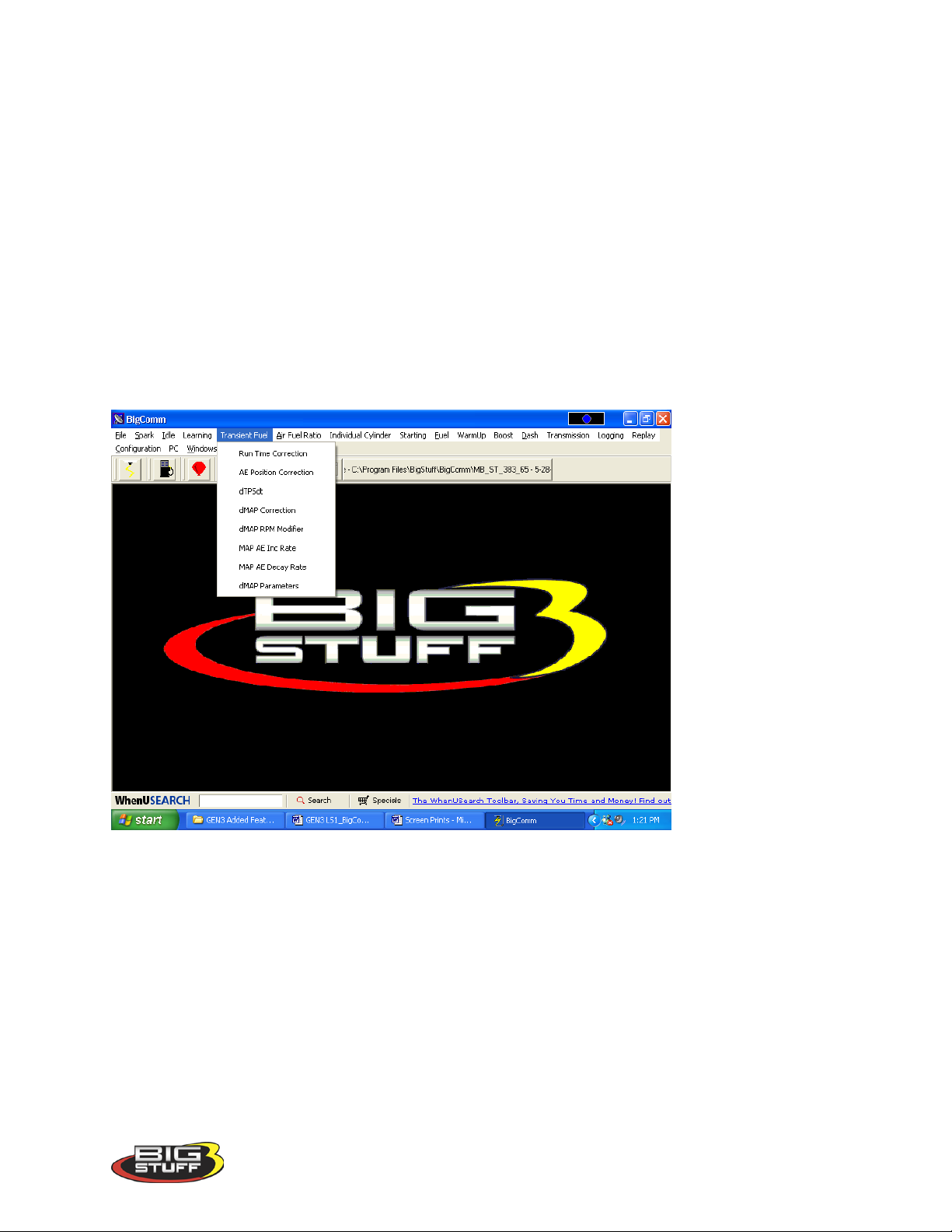
BigStuff3 Pro SEFI System (LS1)
MAP Transient Fuel: MAP (+) Transient Fuel can be compared to a carburetor’s power valve.
It is used to increase the base fuel pulse width when the manifold pressure increases significantly
for a slight change in throttle opening. MAP (-) Transient Fuel is used to decrease the base fuel
pulse width when the manifold pressure decreases significantly as a result of the throttle blades
being closed.
The MAP (+) and (-) Transient Fuel control is comprised of 5 primary tables and 1 secondary
table. Each of the tables play an integral role as to how the base fuel pulse width will be
increased or decreased for a given change in manifold pressure. Below, is a description of how
and when each of the tables is used by the ECU.
From the tool bar on Main Menu screen, left click on “Transient Fuel”. The screen below will
open. The following paragraphs will describe how to calibrate each of the Transient Fuel drop
down selections.
49. dMAP Correction (F10 – “Quick Key”)
The first table is dMAP Correction. It is used to determine the percent fuel correction, either
positive or negative, for a change in manifold pressure (dMAPdt). The ECU calculates the
change in manifold pressure every 52 milliseconds (ms) as long as the throttle is moving. The
ECU will increase or decrease the base pulse width relative to the dMAP Correction table’s %
correction value (i.e. 100%).
Changes in MAP need to be compensated for by increasing or decreasing fuel synchronously to
the base fuel pulse width. Each cell in the input table represents eight (2) kPa increments.
While the engine is running, a “real-time Ellipse” will move within the dMAP Correction table
relative to the current % Correction “operating point”!! Use it as a point of reference to help
calibrate the dMAP Correction table.
Version 1.0 76
Page 78
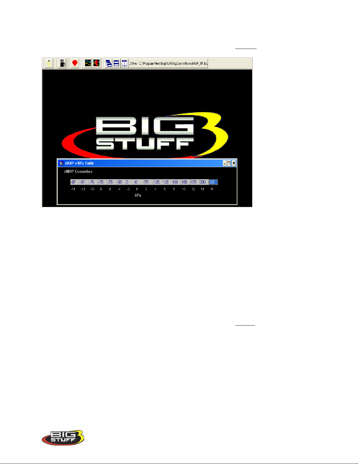
BigStuff3 Pro SEFI System (LS1)
To change a value in the dMAP Correction table, move the cursor using the PC’s mouse or
arrow keys to the cell to be changed. Input the desired value and hit “Enter” to save the change.
50. dMAP RPM Modifier (F10 – “ Quick Ke y”)
The second table used to calibrate the MAP Transient Fuel is the dMAP RPM Modifier table.
Inputs to the table are used to increase or decrease the dMAP correction as a function of engine
RPM. The positive or negative value inputted into the table is the percent (%) applied to the
dMAP Correction table relative to the RPM (see below).
While the engine is running, a “real-time Ellipse” will move within the dMAP RPM Modifier
table relative to the current RPM “operating point”. Use it as a point of reference to help
calibrate the dMAP RPM Modifier table.
To change a value in the dMAP RPM Modifier table, move the cursor using the PC’s mouse or
arrow keys to the cell to be changed. Input the desired value and hit “Enter” to save the change.
Version 1.0 77
Page 79
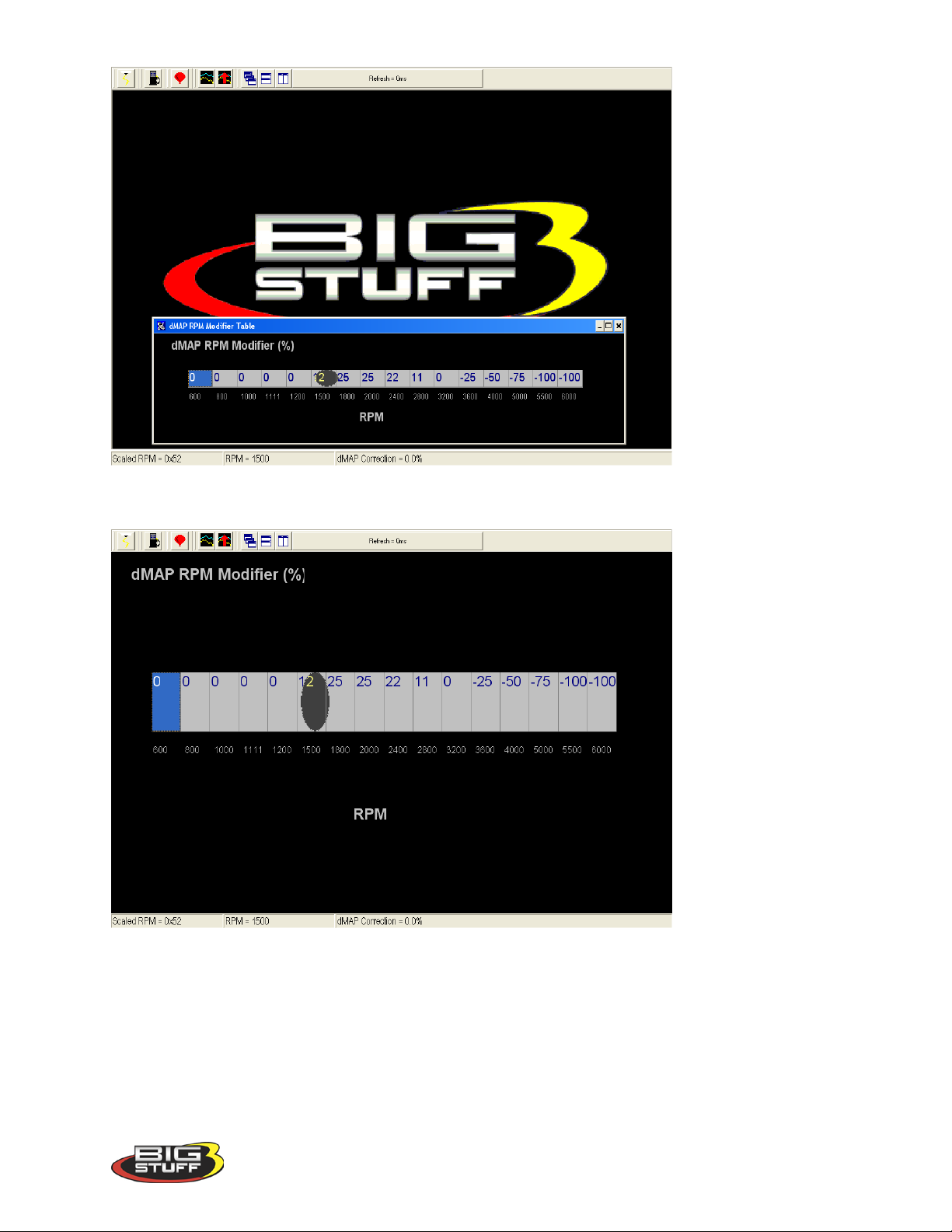
Same screen as above with the window maximized.
BigStuff3 Pro SEFI System (LS1)
51. MAP AE Decay Rate
The third table is MAP AE Decay rate. It is used to determine how quickly to decrease the
Positive dMAP correction value after accelerating the engine at a given coolant temperature.
The ECU decrements the dMAP correction by the MAP AE Decay Rate. A MAP AE Decay
Rate of 3 represents 3 crank interrupts per 1 step decrease of the dMAP Correction until it
reaches zero. In other words, if you input the number 3 into the table, after 3 crank interrupts the
Version 1.0 78
Page 80
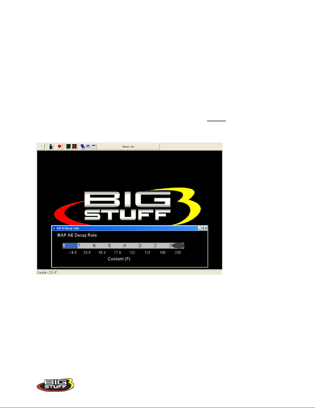
BigStuff3 Pro SEFI System (LS1)
dMAP Correction will decrease 1 step. This 3 interrupt for 1 step process continues until the
dMAP correction reaches zero.
The MAP AE Decay rate table’s fixed values (x-axis) represent coolant temperature, which
increase from left to right. The MAP AE Decay rate input values need to decrease as coolant
temperature increases. The smaller the value in the table, the quicker the fuel is taken out or
decayed.
While the engine is running, a “real-time Ellipse” will move within the MAP AE Decay rate
table relative to the current engine Coolant Temperature “operating point”. Use it as a point of
reference to help calibrate the MAP AE Decay rate table.
To change a value in the MAP AE Decay rate table, move the cursor using the PC’s mouse or
arrow keys to the cell to be changed. Input the desired value and hit “Enter” to save the change.
The inputs shown in the table below can be used as a baseline.
52. MAP AE Inc Rate
The fourth table is MAP AE Inc Rate. It is used to determine how quickly to increase the
Negative dMAP correction value after decelerating the engine at a given coolant temperatu re.
A MAP AE Inc Rate of 3 represents 3 crank interrupts per 1 step increase of the dMAP
Correction until it reaches zero. In other words, if you input the number 3 into the table, after 3
crank interrupts the dMAP Correction will increase 1 step. This 3 interrupt for 1 step process
continues until the dMAP correction reaches zero.
The fixed axis values in the MAP AE Inc Rate table represent coolant temperature, which
increases from left to right. The MAP AE Inc Rate table’s input values need to increase as
coolant temperature increases. The larger the value in the table, the slower the fuel is added.
Version 1.0 79
Page 81
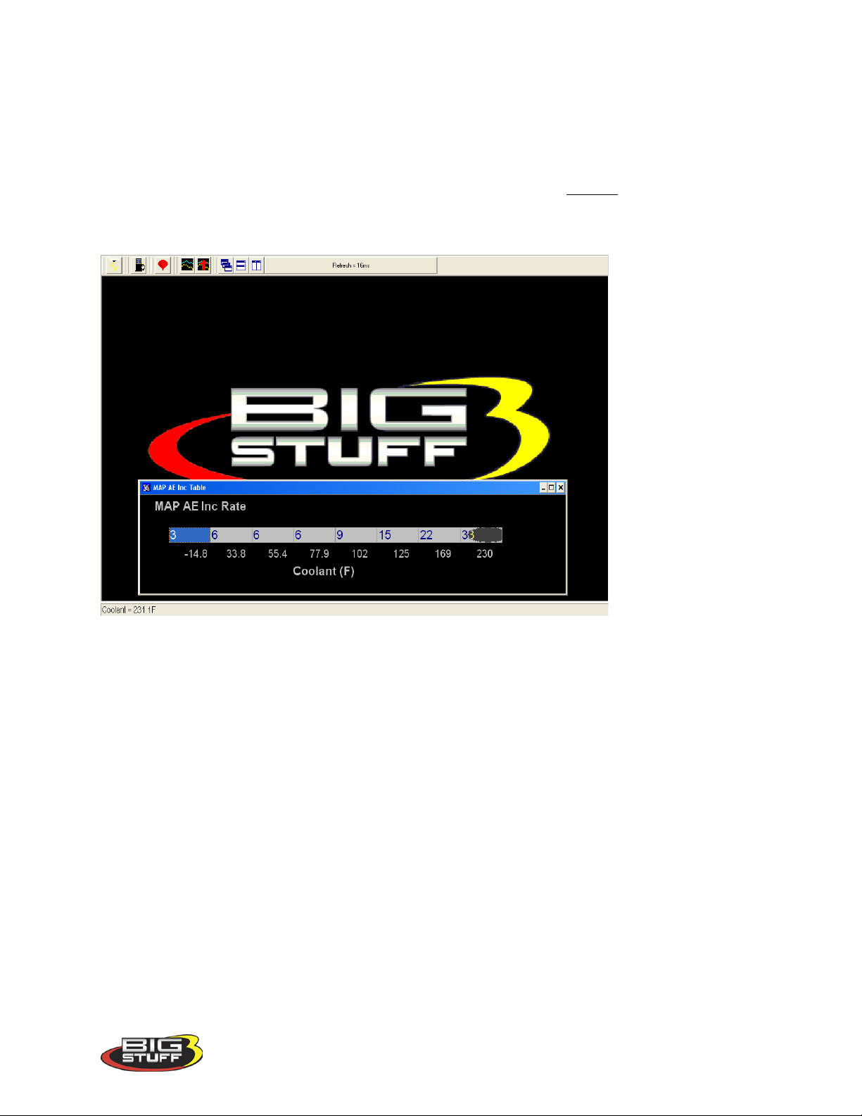
BigStuff3 Pro SEFI System (LS1)
While the engine is running, a “real-time Ellipse” will move within the MAP AE Inc Rate table
relative to the current engine Coolant Temperature “operating point”. Use it as a point of
reference to help calibrate the MAP AE Inc Rate table.
To change a value in the MAP AE Inc Rate table, move the cursor using the PC’s mouse or
arrow keys to the cell to be changed. Input the desired value and hit “Enter” to save the change
The inputs shown in the table below can be used as a baseline.
53. Run Time Correction
The fifth table is Run Time Correction. It only influences the Positive dMAP and dTPS
Correction Values for a short period of time after the engine is running. (i.e. up to 8 minutes).
The Run Time Correction table’s value is used to increase the positive dMAP Correction value.
Therefore, if the current dMAP correction value is 200% and the Run Time Correction value is
25%, the ECU will increase the dMAP 200% correction value by 25%, relative to the time at
which the acceleration event occurred.
The amount of Run Time Correction fuel is decreased as time transpires and the engine warms
up. The first cell in the table, all the way to the left, represents the first ½ minute of engine run
time. The cell all the way to the right represents the end or eighth minute of engine run time.
The Run Time Correction table’s input values need to decrease as you work from the left to
right.
While the engine is running, a “real-time Ellipse” will move within the Run Time Correction
table relative to the current Run Time Modifier “operating point”. Use it as a point of reference
to help calibrate the Run Time Correction table.
Version 1.0 80
Page 82
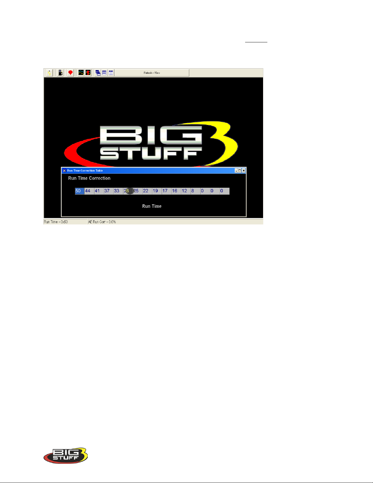
BigStuff3 Pro SEFI System (LS1)
To change a value in the Run Time Correction table, move the cursor using the PC’s mouse or
arrow keys to the cell to be changed. Input the desired value and hit “Enter” to save the change
The inputs shown in the table below can be used as a baseline.
54. dMAP Parameters
The Secondary Transient Fuel table is dMAP Parameter Configuration. This table is used to
control auxiliary MAP and TPS transient and base fuel functions.
The first entry of the dMAP Parameter Configuration table is Asynchronous Acceleration
Enrichment (AAE). It is used to set the MAP transient fuel thresholds relative to MAP (kPa) and
TPS (%) values. Below, is a brief description of each.
• MAP Limit: Establishes the MAP value in kPa at which the dMAP transient fuel is
disabled. For example, if the MAP Limit value is set to 80 kPa, the dTPSdt transient fuel
will be disabled above MAP values of 80 kPa.
• TPS % Clip: Establishes the TPS value, as a percentage, at which the dMAP transient
fuel is disabled. For example, if the TPS % Clip value is set to 80 %, the dMAP transient
fuel will be disabled above TPS values of 80 %.
The second entry of the dMAP Parameter Configuration table is Deceleration Fuel Cut Off
(DCFO). It is used to calibrate when the Base Fuel Map pulse width fuel is turned off and on
relative to MAP (kPa) values. Below, is a brief description of each.
• DCFO On: Establishes the MAP value in kPa at which the Base Fuel Map pulse width is
momentarily disabled. It is used to calibrate deceleration drivability. For example, if the
DCFO On value is set to 30 kPa, the base pulse width will go to zero, 2.5 seconds after
Version 1.0 81
Page 83
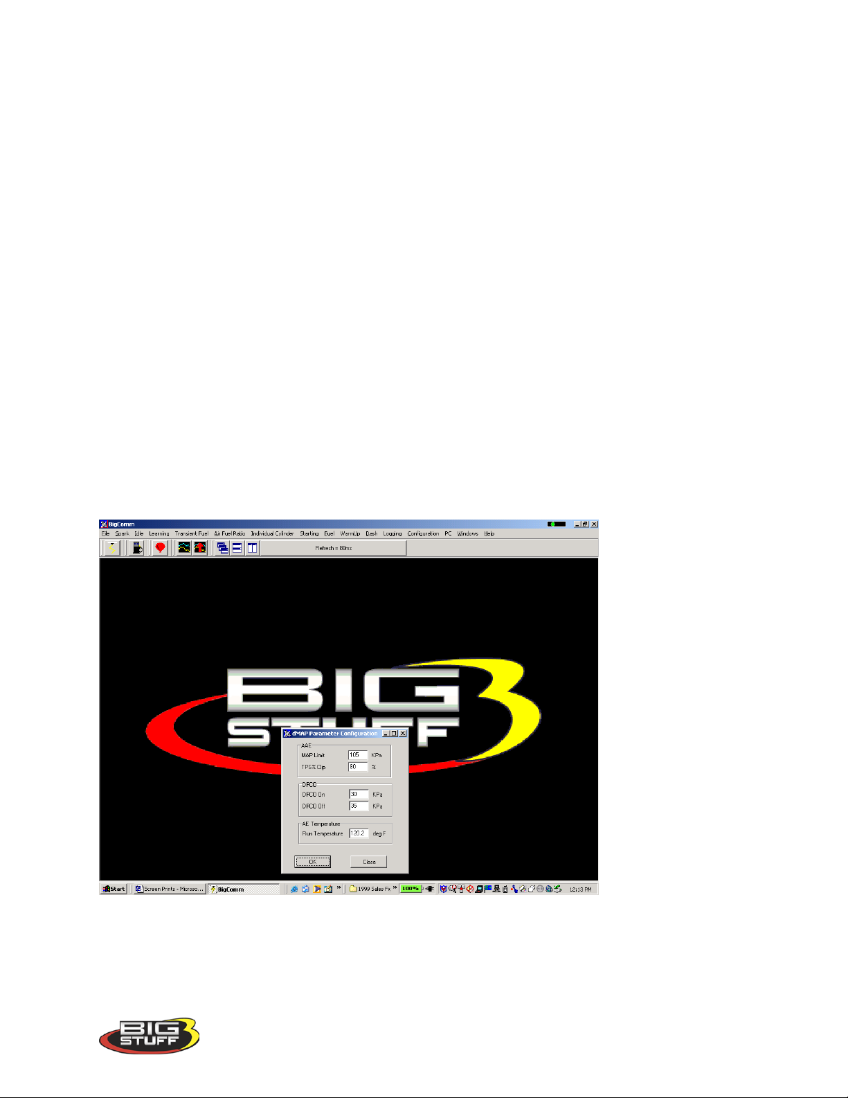
BigStuff3 Pro SEFI System (LS1)
falling below a MAP value of 30 kPa, with the throttle closed. The Base Fuel Map pulse
width is turned back on based upon the DCFO Off value (see DCFO Off).
• DCFO Off: Establishes the MAP value in kPa at which the Base Fuel Map pulse width is
re-enabled. It is used to calibrate deceleration drivability. Typically, the DCFO Off value
is set to 5 kPa above the DCFO On value. For example, if the DCFO On value is set to 30
kPa the DCFO Off value should be set to 35 kPa. Once the MAP value exceeds 35 kPa,
the Base Fuel Map pulse width is turned back on.
The third and final entry of the dMAP Parameter Configuration table is Acceleration Enrichment
(AE) Temperature. It is used to disable the affect of the Run Time Correction multiplicative
scalar value has on the Positive dMAP Correction and dTPS Transient fuel values relative to an
engine coolant temperature (deg F). Below, is a brief description of the AE Temperature “Run
Temperature” setting.
Run Temperature: Establishes the engine coolant temperature in deg F at which the Run Time
Correction multiplicative scalar term no longer influences the Positive dMAP Correction or TPS
Transient fuel values. Therefore, if the Run Temperature value is set to 120 oF, the Run Time
Correction multiplicative scalar term will no longer influence the Positive dMAP Correction or
TPS Transient fuel values at engine coolant temperatures above 120 oF.
To change a value in these tables, move the cursor using the PC’s mouse or arrow keys to the
cell to be changed and input the desired value. Then click on OK to save the changes.
TPS Transient Fuel
The TPS transient fuel control is comprised of 2 primary tables. Each of the table’s play an
integral role as to how the TPS Transient Fuel requirements are calibrated for abrupt throttle
changes that causes the engine to accelerate. TPS transient fuel is asynchronously injected
Version 1.0 82
Page 84

BigStuff3 Pro SEFI System (LS1)
relative to a rate of throttle change (dTPSdt). The asynchronous pulse can be modified relative
to the throttle position where the acceleration event occurred (AE Position Correction). Below,
is a description of how the TPS Transient Fuel requirements are calibrated using the dTPSdt and
AE Position Correction tables.
55. dTPSdt
The first TPS Transient Fuel control table is dTPSdt. It can be compared to a carburetor’s
accelerator pump shot. The ECU uses the dTPSdt table value to compute the size of the
Asynchronous Pulse Width (APW) for a given rate of throttle change. It does so by sensing the
rate of the throttle change and then using the corresponding dTPSdt table value to calculate the
size of the asynchronous pulse width. For example, if the ECU detected a throttle change of 10
degrees / second (dTPSdt), it would immediately look up the corresponding dTPSdt table value
of let’s say 2ms. After the asynchronous pulse is looked up, the ECU then uses AE Position
Correction table (see below) to modify the asynchronous pulse size relative to the throttle
position at which the dTPSdt event occurred. Note: If the dTPSdt table value is zero, no TPS
transient fuel will occur.
Working from left to right, each input cell in the dTPSdt table represents a 1% change in throttle
angle for a total percent change of 15%. This is plenty of resolution since the ECU looks for
changes every 20 milliseconds. As a reference point, it typically takes approximately 250
milliseconds for a person to slam the throttle open.
While the engine is running, a “real-time Ellipse” will move within the dTPSdt table relative to
the current dTPSdt “operating point”. Use it as a point of reference to help calibrate the dTPSdt
table.
To change a value in the dTPSdt table, move the cursor using the PC’s mouse or arrow keys to
the cell to be changed. Input the desired value and hit “Enter” to save the change. The values
need to be larger as you work from the left to right. The greater the throttle angle rate of change,
the larger the dTPSdt table value needs to be.
Version 1.0 83
Page 85
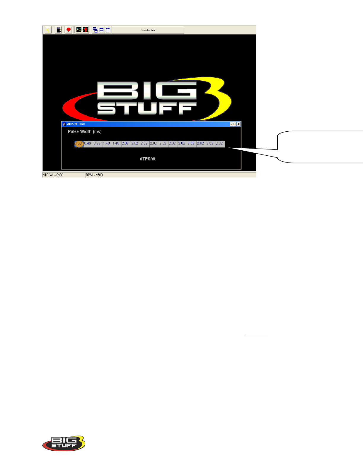
BigStuff3 Pro SEFI System (LS1)
Working from left to right, each
cell equals a 1% change in throttle
angle up to 15
56. AE Position Correction
The second TPS transient fuel control table is AE Position Correction. It can be compared to a
carburetor’s accelerator pump “cam” profile. The ECU uses the AE Position Correction table
value to modify the size of the Asynchronous Pulse Width (APW) relative to the throttle position
at which the dTPSdt event occurred. For example, if a 10o/second dTPSdt event occurred
(resulting in a look up of 2.0 ms) at a 24% throttle position, the ECU would immediately look up
the corresponding AE Position correction value of let’s say -13%. The ECU will then decrease
the 2.0 ms pulse by 13% and output a 1.74 ms pulse. If the same 10o/second dTPSdt event
occurred at a 48% throttle position and the corresponding AE Position Correction value was 31% the APW would then be 2.0 ms – 31% or 1.38 ms.
While the engine is running, a “real-time Ellipse” will move within the A E Position Correction
table relative to the current TPS % “operating point”. Use it as a point of reference to help
calibrate the AE Position Correction table.
To change a value in the AE Position Correction table, move the cursor using the PC’s mouse
or arrow keys to the cell to be changed. Input the desired value and hit “Enter” to save the
change. The greater the TPS %, the larger the AE Position Correction table value needs to be.
The inputs shown in the table below can be used as a baseline.
o
per second.
Version 1.0 84
Page 86
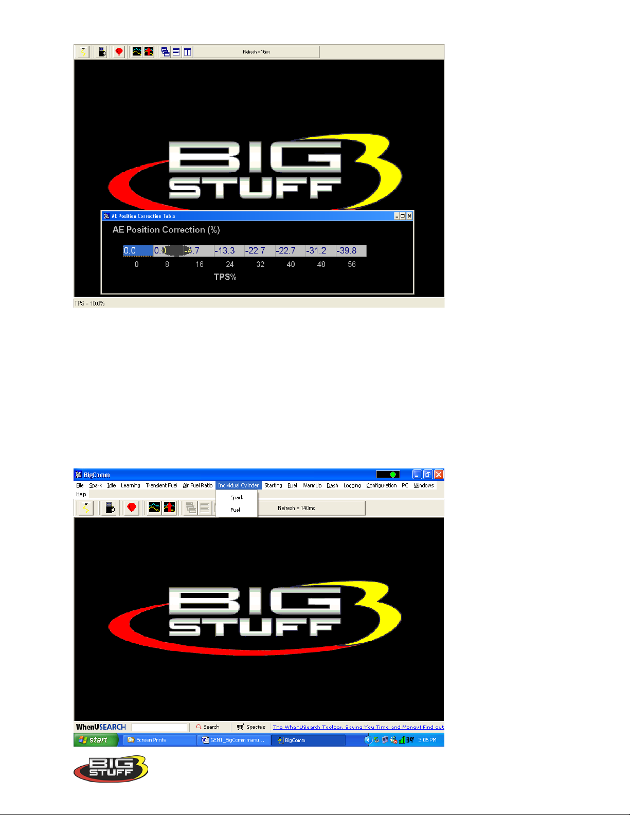
BigStuff3 Pro SEFI System (LS1)
57. Individual Cylinder
This feature allows the user to define the amount of fuel (positive and negative) and spark
advance/retard correction for each cylinder. This feature is used to “calibrate out” intake
manifold inefficiencies.
From the Main Menu screen Tool Bar, left click on “Individual Cylinder.” The screen below
will open. The following paragraphs will describe how to calibrate each of the Individual
Cylinder drop down selections.
Version 1.0 85
Page 87
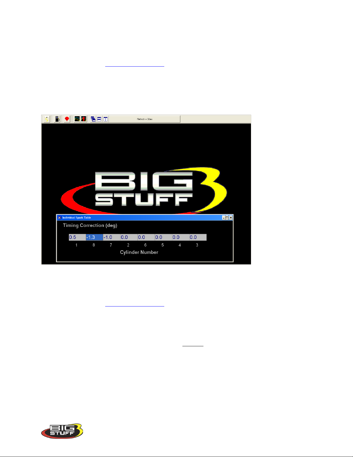
BigStuff3 Pro SEFI System (LS1)
58. Individual Cylinder - Spark
The fixed inputs in the table below represent the firing order configured during the firing order
configuration process (Firing_Order_Config). The input cells allow the user to define the
amount of timing advance or retard (up to 10o) for or each cylinder in the table. Timing
corrections are made to the values in the Spark Table.
Note: The GEN3 LS1 system, with the Coil-on-Plug (COP) ignition system, is the only GEN3
system with bi-directional timing compensation.
59. Individual Cylinder - Fuel
The fixed inputs in the table below represent the firing order configured during the firing order
configuration process (Firing_Order_Config). The input cells allow the user to define the
percent of fuel to be increased or decreased (up to 25%) for or each cylinder in the table. The
individual fuel correction values modify the base pulse width in the Fuel Table.
To change a value in these tables, move the cursor using the PC’s mouse or arrow keys to the
cell to be changed. Input the desired value and hit “Enter” to save the change.
Version 1.0 86
Page 88
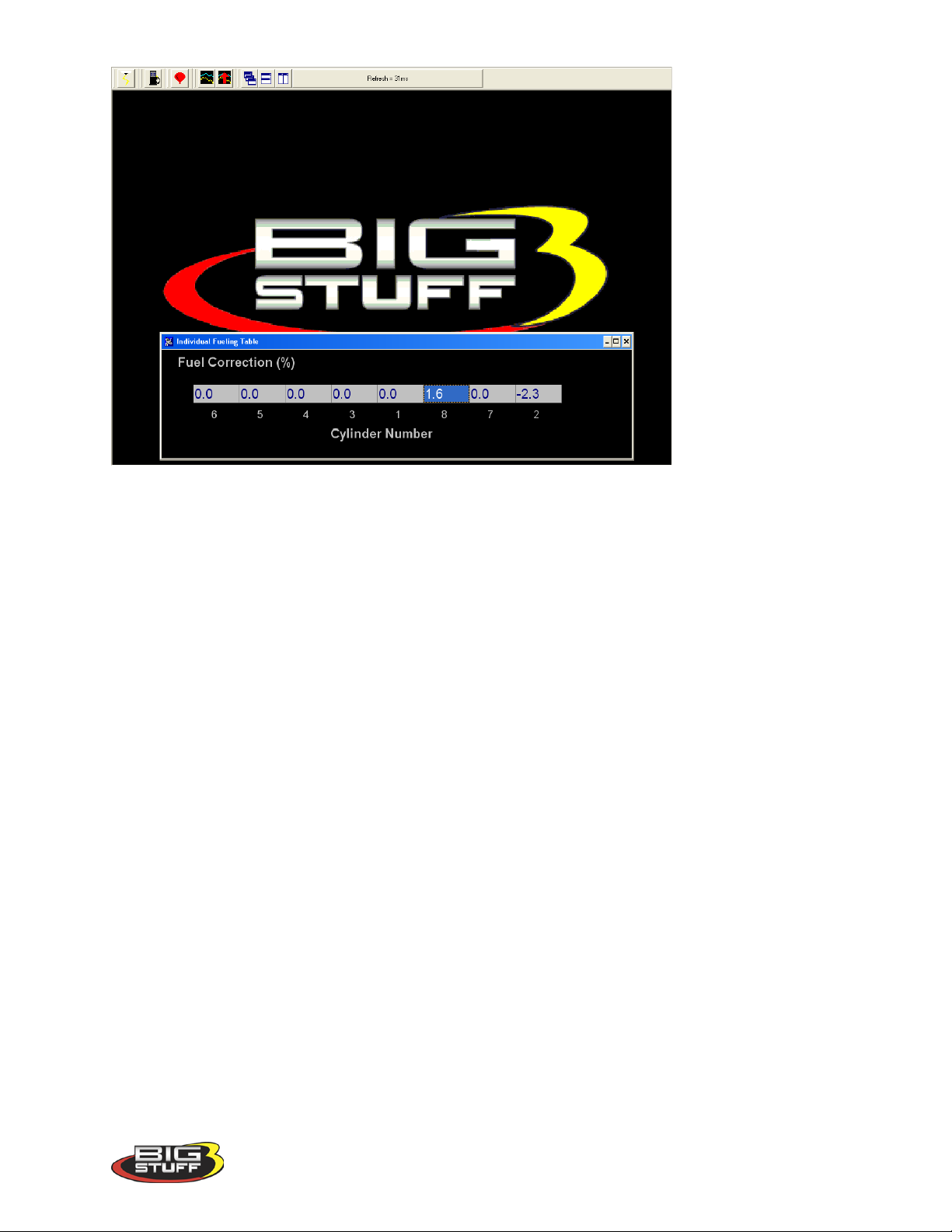
BigStuff3 Pro SEFI System (LS1)
60. Boost
The GEN3 ECU allows the user to control boost parameters. Two boost strategies can be
employed.
1. A Pulse Width Modulated (PWM) valve can be used to control boost as a function of
engine RPM. The duty cycle of the valve can be changed as a function of engine speed.
2. A “staged” boost strategy can also be used. Up to three stages of boost can be switched
on (using solenoid valves) in a user defined, timed sequence. The vehicle can be
configured to come out of the hole with one stage applied and as time (distance down the
track) expires, the second and third stages of boost can be turned on.
The “Boost Parameters” can be configured from the Main Menu screen Tool Bar. Left click on
“Boost.” The following screen will open.
Version 1.0 87
Page 89
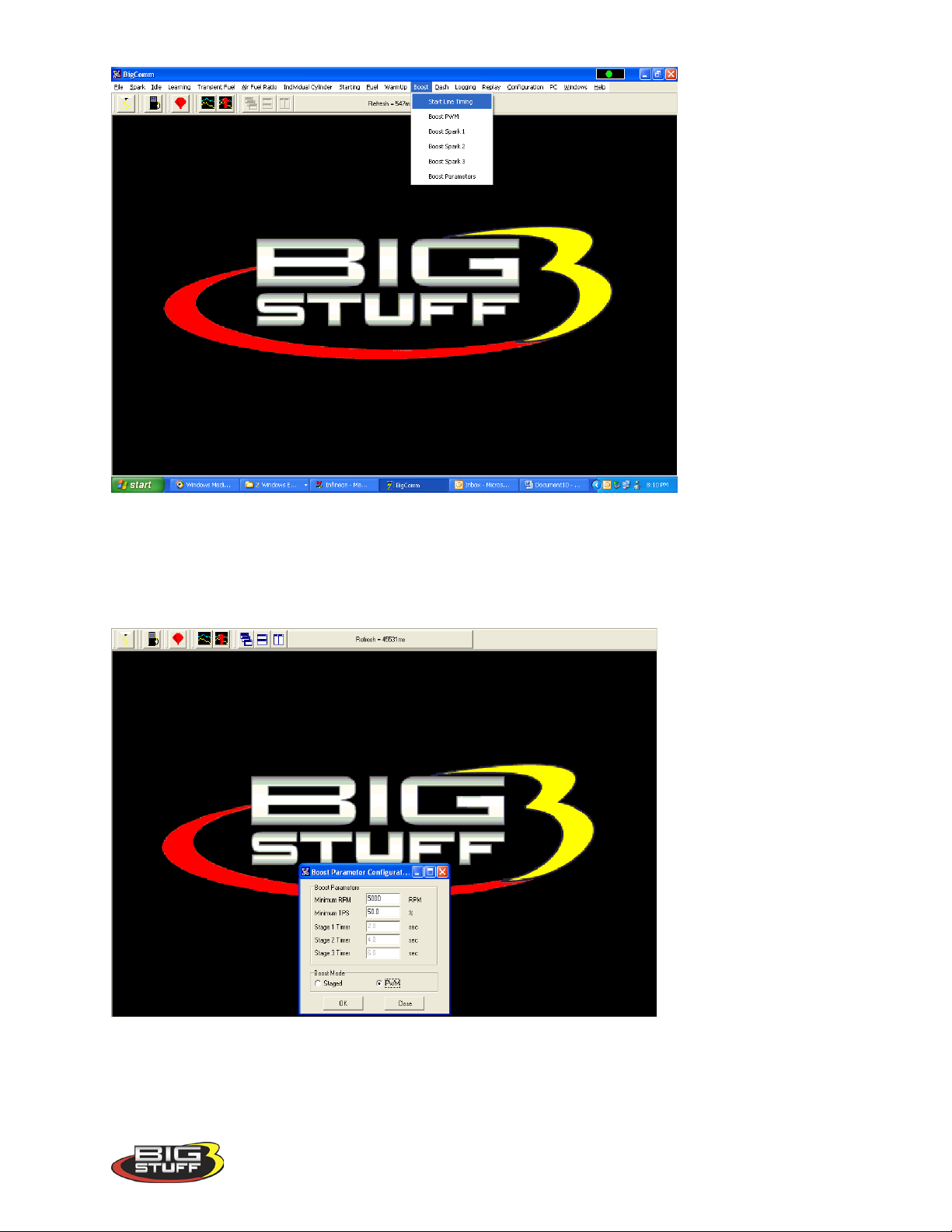
BigStuff3 Pro SEFI System (LS1)
Keep the left mouse button depressed and slide the mouse pointer down until “Boost
Parameters” is highlighted. Release the left mouse button. The screen below will open.
61. Boost Parameters
The GEN3 ECU allows the user to control boost parameters in two (2) modes; Staged or Pulse
Width Modulated (PWM).
Version 1.0 88
Page 90
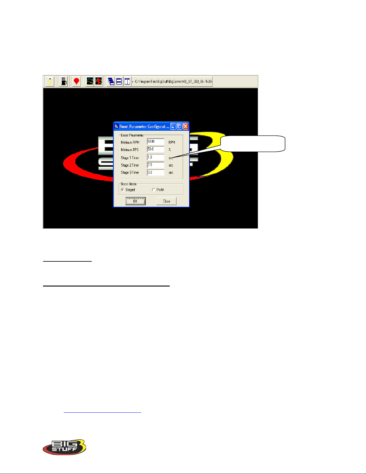
BigStuff3 Pro SEFI System (LS1)
.1-second reso lution
Staged mode turns on boost stages (solenoid valves) in a user defined, time sequence. PWM
mode assumes the boost system is configured with a PWM boost valve. When the PWM mode
is enabled the Stage 1 – 3 timer input windows are made inactive, as shown in the screen print
above. When Staged mode is selected, the Stage Timer input windows are active as shown in
the screen print below.
The stage timer starts once the following criteria are satisfied:
Minimum RPM – This input establishes the minimum RPM the engine must reach to initiate the
boost timing sequence.
Minimum Throttle Position Sensor (TPS) – This input establishes the minimum throttle
position the TPS sensor must reach to initiate the boost timing sequence.
Both the Minimum RPM and Minimum Throttle Position inputs must be satisfied before the
boost timing is initiated.
62. Boost PWM
Before this table becomes active, PWM needs to be selected in the Boost mode window of the
boost configuration table. The values inputted into the PWM window below represent the
percent (%) duty cycle of the boost valve. The PWM boost function will run continuously when
this mode is enabled. The solenoid valve used must be a Normally Closed (NC) valve. The
valve is T’d into the line from the turbo compressor to the bottom of the wastegate diaphragm.
The solenoid valve resistance must not be lower than 14 ohms w /14 volt supply (1 A) . One end
of the solenoid valve is connected to Switched Ignition and the other to the Boost Connector, Pin
B. See Boost_Connector_Pin_Out.
Version 1.0 89
Page 91
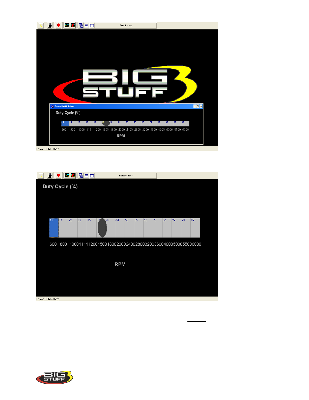
Same as screen above with window maximized.
BigStuff3 Pro SEFI System (LS1)
To change a value in the Boost PWM table, move the cursor using the PC’s mouse or arrow
keys to the cell to be changed. Input the desired value and hit “Enter” to save the change.
63. Boost Staged
When “Staged” mode is selected the time intervals between the boost stages need to be
configured. In the Boost Parameters table above, these inputs are defined as Stage 1, Stage 2
and Stage 3. Before the staged boost sequence can be enabled, 12 Volts needs to be present at
Version 1.0 90
Page 92
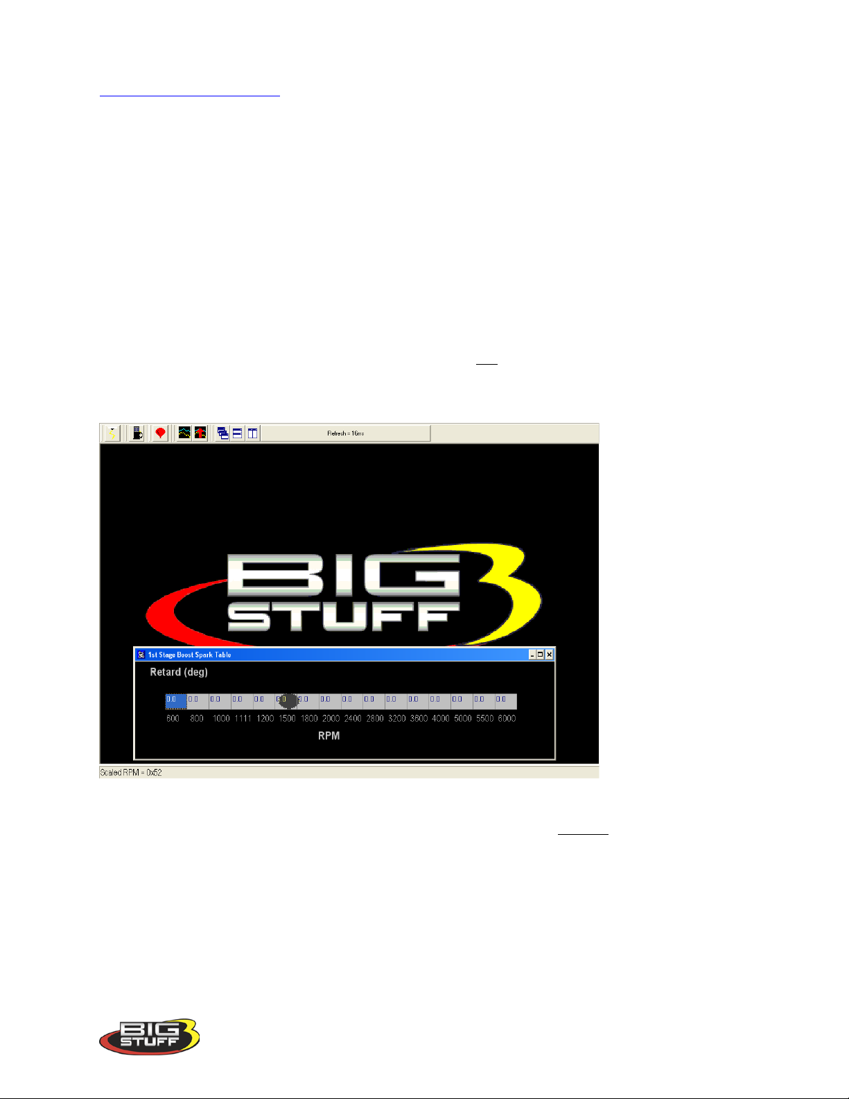
BigStuff3 Pro SEFI System (LS1)
the Timer Enable pin, which is Pin A of the 4-way Boost connector on the main wire harness
Boost_Connector_Pin_Out. A clutch switch or trans brake button should be wired between the
timer enable pin and a 12-volt source. A toggle switch can be added between the 12V source
and the clutch switch or transmission brake button to allow the timer enable pin to be turned on
and off.
In the example table above, Stage 2 will be activated two (2) seconds after “time zero” and Stage
3 will be activated three seconds after time zero.
Note: Once the stages are turned on, they stay on until the TPS and/or RPM criteria is no longer
true or the Timer Enable goes low/off.
Boost Spark Tables 1, 2 & 3
The Boost spark tables allow the user to set the spark retard (degrees) timing as a function of
RPM for each stage. The retard timing for each stage is not additive. In other words, when the
second stage comes on it replaces the timing values of the first stage and when the third stage
comes on it replaces the timing values of the first and second stage.
To change a value in the Stage 1 Boost Spark table, move the cursor using the PC’s mouse or
arrow keys to the cell to be changed. Input the desired value and hit “Enter” to save the change.
64. Start (Starting) Line Timing
The GEN3’s Starting Line Timing feature allows the engine to build boost at the starting line.
The feature is primarily focused at stick shift cars, but works equally well with automatic cars.
The Starting Line Timing feature can be used in conjunction with the 2-Step to maximize
starting line performance!
Version 1.0 91
Page 93
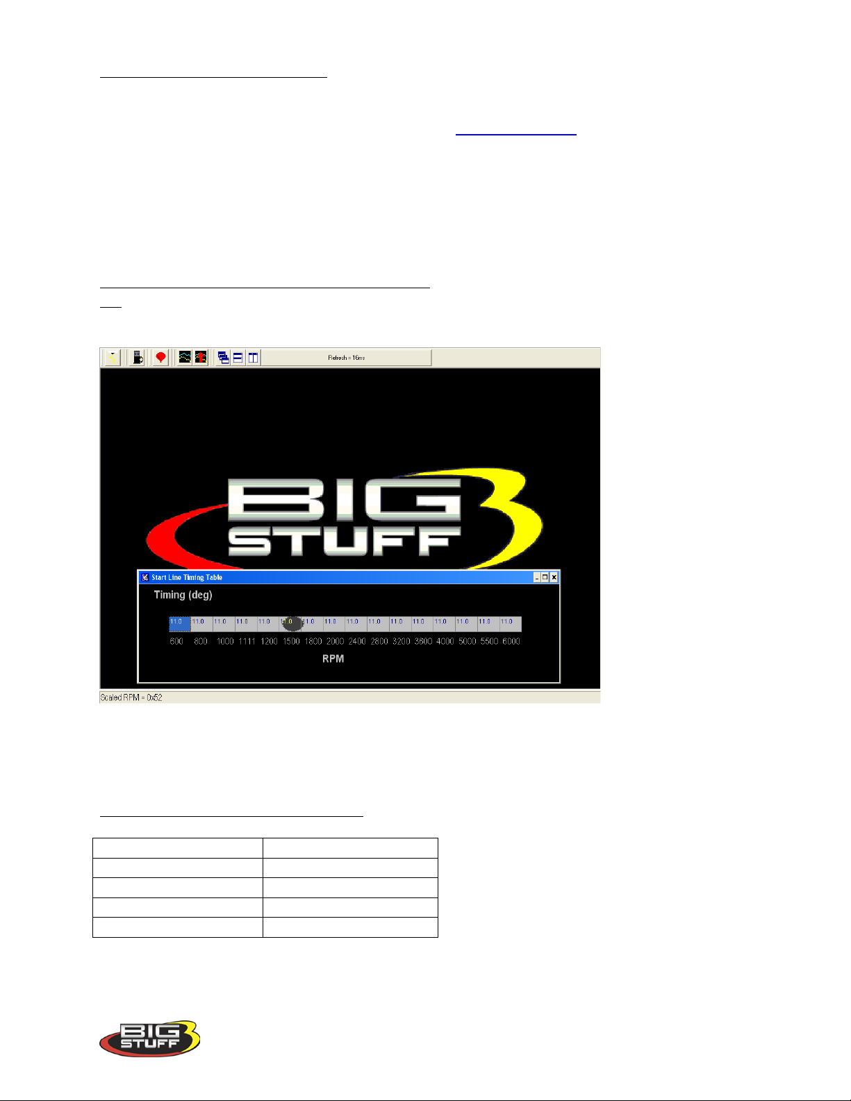
BigStuff3 Pro SEFI System (LS1)
Connector Pin
Function
A
Timer Enable
B
Stage 1 / PWM Output
C
Stage 2
D
Stage 3
How to Use With Stick Shift Cars - For stick shift cars, the ignition timing needs to be retarded
in order for the engine to build boost at the starting line (with the clutch in).
If this feature is used with the 2-Step, make sure that Boost_Parameters RPM input is set 1,500
RPM below the 2-Step RPM enable point. Once the Boost Parameters TPS and RPM criteria are
satisfied the ECU will use the timing values from the Starting Line Timing table. If the RPM
and TPS criteria are not met, the ECU will default to the timing values in the main spark map.
The values in the main spark map may not allow the engine to build boost, so it is important to
properly configure the relationship between the Boost Parameters RPM and TPS criteria and the
2-Step RPM It takes +12V to activate the 2-Step.
How to Use With Automatic (transmission) Cars – For automatic cars, the ignition timing should
not be retarded. You want to use whatever ignition timing values the engine requires to build
boost and make the car leave hard.
Note: The timing values inputted into the Start Line Timing table are the absolute values the
ECU will use when the Boost Parameters minimum RPM & TPS are reached! If you enter 0
in the table, there will be no Starting Line timing function.
Boost Connector Pin-out Configuration
Version 1.0 92
Page 94
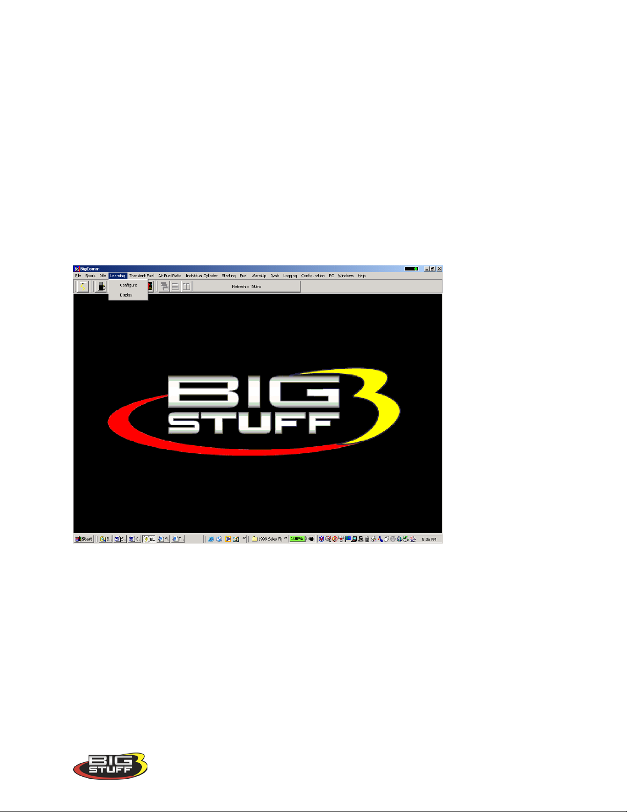
BigStuff3 Pro SEFI System (LS1)
65. Learning
The primary function of the Learning feature is to minimize the amount of O2 correction
required to achieve the user defined values in the air/fuel ratio table. If learning is enabled, the
ECU monitors the % O2 correction. If the % O2 of correction is equal to or greater than 5%, the
ECU begins to Learn. Once it begins to learn, the ECU corrects the corresponding base fuel
pulse width (BLM up to +/- 25%) until it is within +/- 5% of the value in air/fuel ratio table. The
Learning function is only applicable to fuel correction, not Spark. The ECU does not allow the
Learning function to be enabled at idle or Wide Open Throttle (.3 to .9 Bar).
66. Configure (Learn Parameters)
To configure the Learn parameters, go to the Main Tool Bar and left mouse click on Learning.
The following screen will open.
Keep the left mouse button depressed and slide the mouse cursor down until Configure is
highlighted. Release the mouse button and the drop down screen below will open allowing the
user to Configure the Learning feature.
Version 1.0 93
Page 95
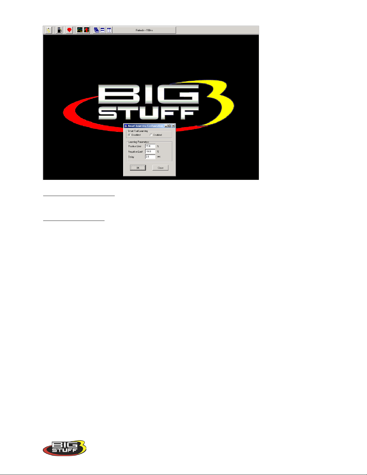
BigStuff3 Pro SEFI System (LS1)
Enable/Disable Learni n g - To enable or disable Learning, left mouse click the appropriate button.
Learning Parameters – Assuming “Learning Enabled” was selected, the following parameters need to be set.
• Positive & Negative Limit – The correction limit (+/-25%) that the ECU will allow the
Learning function to modify the base fuel table values.
• Delay – The amount of time the engine needs to be operating within a given speed and
load cell before the ECU will allow the Learning function to become active.
To change a value in these tables, move the cursor using the PC’s mouse or arrow keys to the
cell to be changed and input the desired value. Then click on OK to save the changes.
67. Learning Display Table
The three (3) cell by four (4) cell Learning Display Table corresponds to the sixteen (16) cell
by sixteen (16) cell base fuel table. One cell in the Learning Display Table covers sixteen (16)
cells in the base fuel map. As is the case with the base fuel map, the X-axis represents engine
RPM and the Y-axis represents engine Load.
Version 1.0 94
Page 96
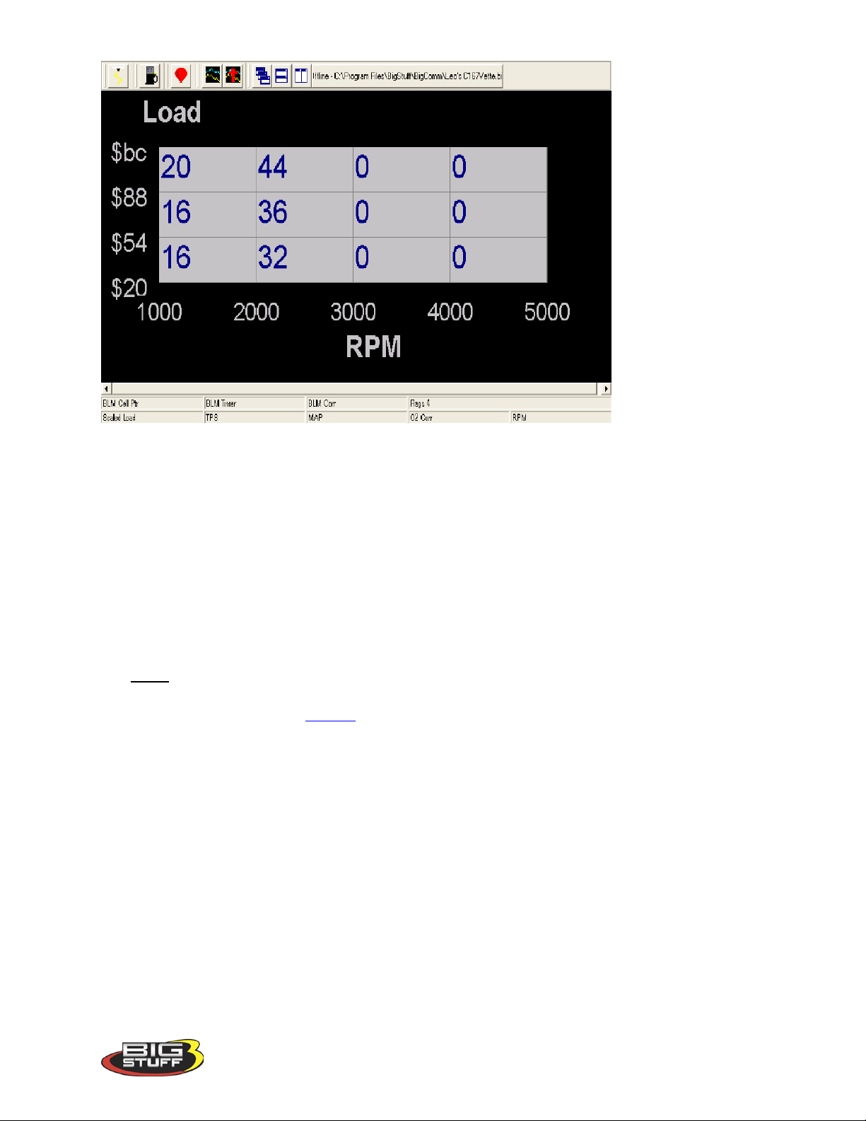
BigStuff3 Pro SEFI System (LS1)
When the user defined delay limit is reached, the active cell (the cell the engine is operating in)
in the Learning Display Table cell turns green to signify the Learning mode is active. While
the cell is green, the ECU drives the O2 correction to within +/-5% of the base fuel value then
turns the cell red to signify the learning has stopped. The fuel corrections, made by the Learning
function, are applied as a percent increase or decrease, to the associated 16 cells in the base fuel
map.
68. Dash
A Dash, (short for Dashboard) can be configured and displayed at the bottom of most of the
“Operating Screens” within the BigComm software. A Dash needs to be selected, configured
and saved as a default before it will appear at the bottom of a BigComm software “Operating
Screen”. Up to thirty-one (31) individual Dashes’ can be configured to display various engine
parameters also referred to as Signals.
When the BigComm software is launched, it uses the “Default Dash” (which contains the 31
separate dash’s) from the C: Program Files/BigStuff/BigComm folder. The “Default Dash” is
actually a compilation of the 31 available dash’s.
The recommended way to configure the “Default Dash” is to configure each of available dash’s,
or most frequently used dash’s, to your liking and then save them as the “Default Dash”. This
way, every time you open the BigComm software, the dash’s will be open to the preferred
configuration.
69. Configure Dash
To configure a Dash, go to Dash on the Tool Bar. Left click on “Dash” and the drop down
screen shown below will open. Keep the left mouse button depressed and slide the mouse
pointer down until “Configure Dash” is highlighted.
Version 1.0 95
Page 97
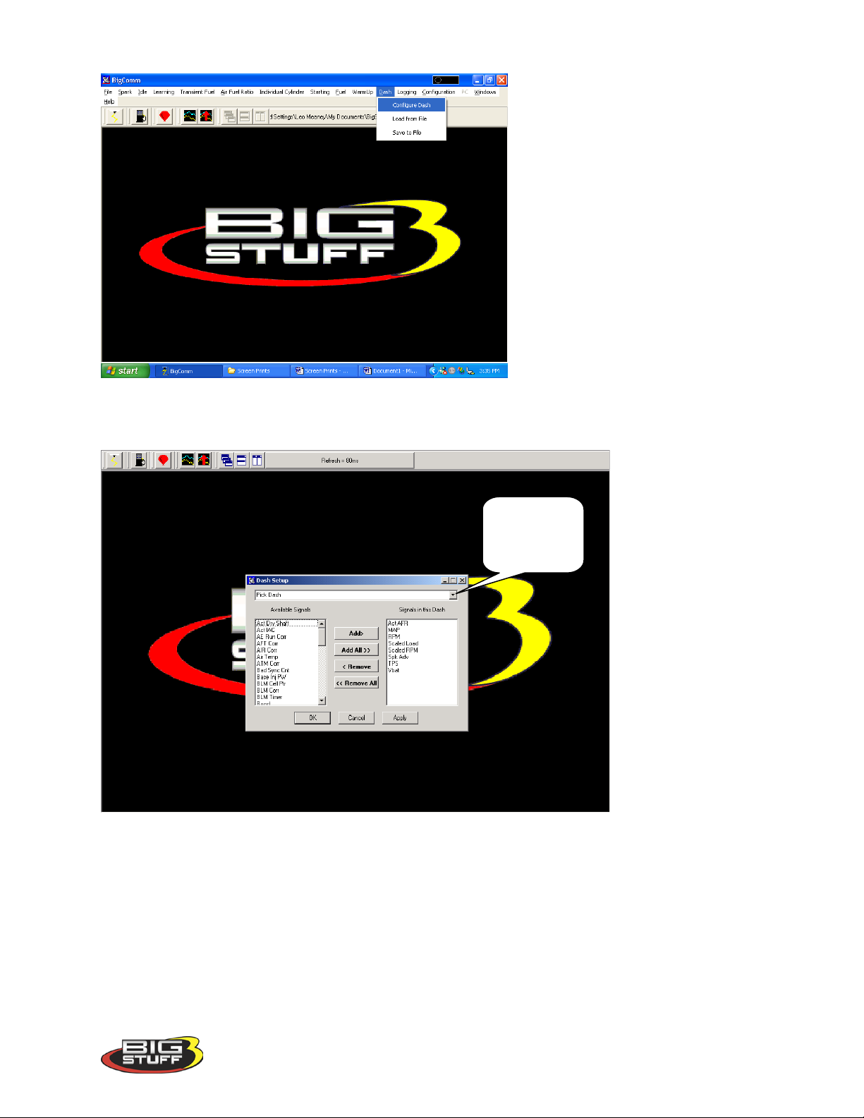
BigStuff3 Pro SEFI System (LS1)
Pick Dash
Release the left mouse button. The screen below will open. Left Click on the “Pick Dash” drop
down screen.
The screen below will appear.
drop down
screen
Version 1.0 96
Page 98
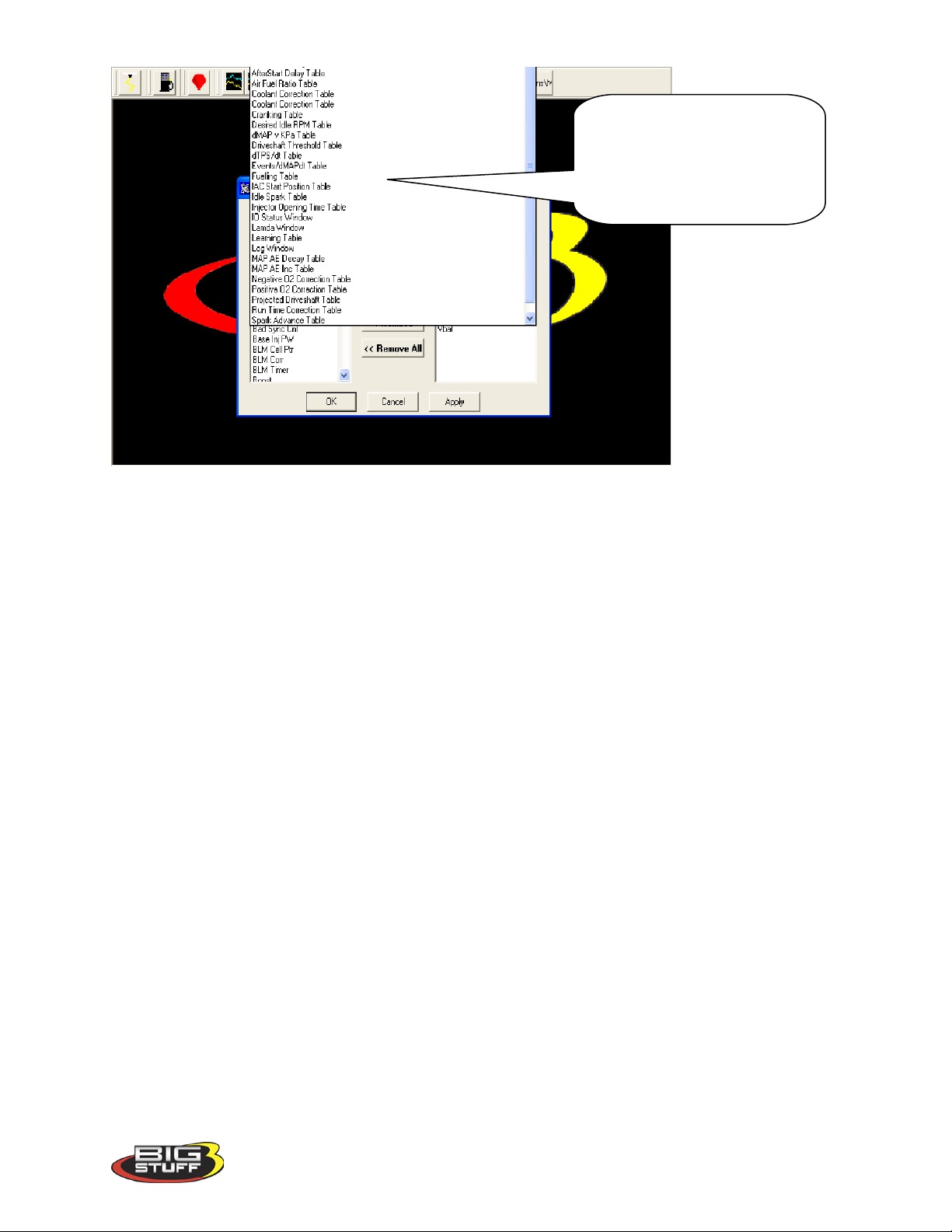
BigStuff3 Pro SEFI System (LS1)
This is the list of thirty-one (31)
available Dashboards. Once
configured, these Dashboards
will show up at the bottom of the
corresponding operating screens.
After selecting a Dash to configure, “Signals” need to be selected and added to the Dash. After
the Signals are selected, added and saved, they will be displayed in the Dash at the bottom of the
relevant BigComm software screens. The left side of the drop down screen below shows the
“Available Signals”. The right side of the drop down screen below shows the “Signals in the
Dash”. To add Signals to the Dash, highlight a desired Signal on the left and click Add. The
Signal will move to the right side of the screen (Signals in the Dash). All Signals shown under
“Signals in the Dash” will now appear in the Cranking Fuel screen when that screen is used to
calibrate the Cranking Fuel.
In the Cranking Fuel example below, Air Temp, Base Injector Pulse Width, Coolant, MAP and
TPS where selected and added to “Signals in the Dash”.
Version 1.0 97
Page 99
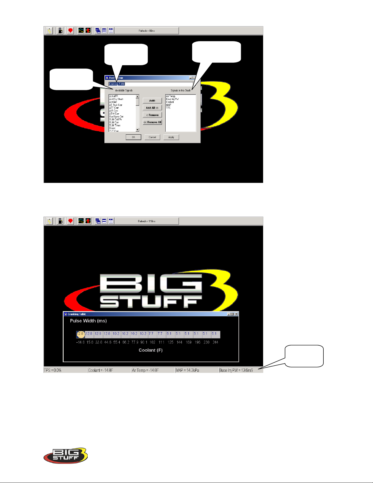
BigStuff3 Pro SEFI System (LS1)
Available
Signal in the
Cranking
Cranking
Fuel Dash
Signals
Dash
In the screen print below notice that the same “Signals” appear in the Dash at the bottom of the
Cranking Fuel screen.
Fuel Dash
70. Save a Dash
Again, the recommended way to configure the “Default Dash” is to configure each of available
dash’s, or most frequently used dash’s, to your liking and then save them as the “Default Dash”.
This way, every time you open the BigComm software, the dash’s will be open to the preferred
configuration.
Version 1.0 98
Page 100
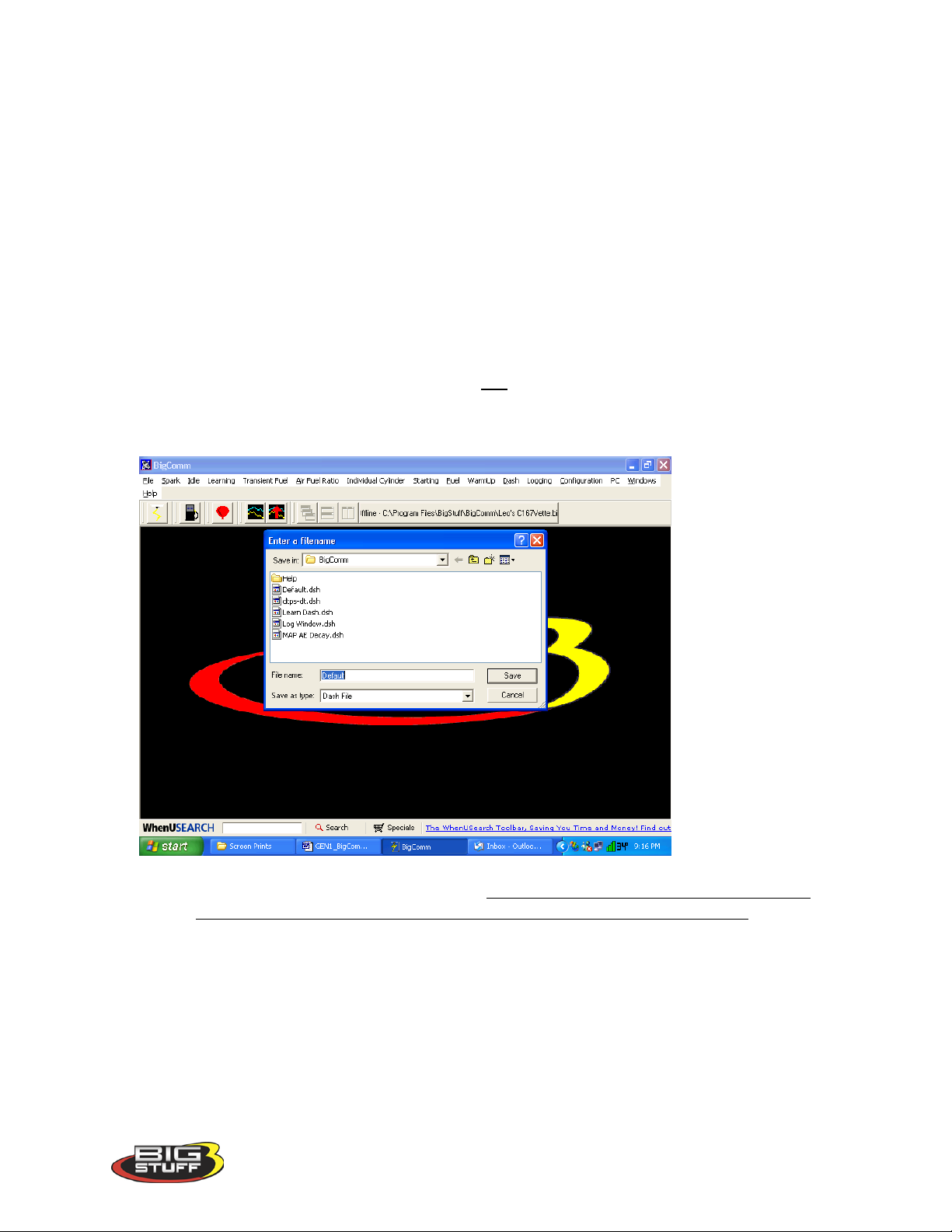
BigStuff3 Pro SEFI System (LS1)
Once the “Default Dash” has been saved, individual dash’s can be changed and saved again as
part of the compilation of dash’s referred to as the “Default Dash”.
The steps for saving a reconfigured Dash, so that it becomes part of the “Default Dash”, are
outlined below:
• After configuring a Dash hit OK at the bottom of the Dash Setup window. The
window will close.
• Go back to Dash on the Main Window tool bar and Select Save To File from the
Dash drop down list. The screen below will open
Note: Before saving the Log Window dash for the first time, you need to
navigate to the C: Program Files/BigStuff/BigComm directory. This step
only occurs the very first time any Dash file is saved. Subsequent Dash file
saves will automatically be saved to the C: Program
Files/BigStuff/BigComm folder.
• Name the file “Default” and hit Save. By selecting “Default” as the file name, the
Log Window dash becomes part of the compilation called “Default Dash”. Again,
the file will be saved to C:/Program Files/BigStuff/BigComm directory.
• A unique file name can also be assigned by typing the name in the “File Name” sub-
window and clicking on Save.
Version 1.0 99
 Loading...