

Page 1

S550.1D
S850.1D
S1300.1D
S2000.1D
Page 2

Page 3

FEATURES
l DO UBLE SIDE P CB AN D SMD COMPO NE NTS.
l FU LL MO SFET DE SI GN.
l LP F AND SUBSON IC C ROSSOVE R.
l AD JUSTAB LE B ASSBOOS T LEVEL.
l AC TIVE X-OV ER F UNCTION .
l HE AVY-DUTY ALUMINUM ALL OY HEATSINK.
l HI GH (Speak er ) OR LOW (RCA ) LE VEL INPUTS.
l OV ERLOAD, O VE RHEAT, HIG H/ LOW VOLTAGE PROT EC TION.
l RO HS COMPLI AN T.
CONTROL FUNCTIONS
1. SPE AKERS
Connect spe akers/sub woofers to th ese termina ls. Be sure t o ch eck wire fo r pr oper
polarity. Never con ne ct the spea ke r cables to c ha ssis grou nd .
2. +12 Volt Power
Connect th is termi na l throug h a FUSE o r C IRCUIT BREAKER t o the pos it ive term inal of
the vehicle b attery or the p ositive ter minal of an iso lated audio s ystem batte ry.
War ning: Alway s p ro tect this po wer cable b y i nstalling a fuse or circ ui t breaker o f t he
appropria te size withi n 18 inches (45 cm) of the batt ery termina l connectio n.
3.Remote Turn On
This t erminal tur ns on th e am pl ifier when ( +)12 v olt is applied to it . Con nect it to the
remote tu rn o n lead of the hea d unit or signa l source.
4.GN D
Connect t his cable d irectly to the f rame of the ve hicle. Ma ke sure the metal fr am e has
been stripped of al l pa int down to the bare m etal. Use the short es t di stance possib le. It is
always a g ood i dea to r eplace the factor y gro un d a t thi s t im e w it h a larg er ca ble e qual to th e
new am plifier power c able o r la rger. C AUTION: Do not conn ec t th is terminal directly to the
vehicle bat tery ground t erminal or an y other facto ry ground poi nts.
5. RCA in put jacks
These RCA in put jacks are f or u se with sourc e un its that ha ve R CA ou tputs. A so urce unit
with a min im um le vel of 200mV is required for proper opera ti on. The use of high quali ty
twisted pa ir cab le s is re co mmended to decre as e the p os sibilit y of radi at ed noi se enterin g the
system.
6. Hig h level input s
The hi gh level i nputs are fo r use with speaker lev el wiring. Some source units do no t
have RC A o utputs, so use t his ter mi nal for speaker level s ig nal inp ut . CAUTI ON : Never use
high level in put when RCA inp uts availab le.
Page 4
CONTROL FUNCTIONS
7. REM OTE
Connect th e remote controlle r to cont ro l the sub wo ofer amp lifier vol ume from th e driver
seat locati on, for ease of a djustment d uring playi ng.
8. LEV EL Control
The level contr ol wi ll match the amplifi ers sensitiv ity t o t he source units si gn al voltage.
The Operati ng range is 200 mV minimum to 5 V maximum. This is NOT a v olume con tr ol!
9. Low P ass Filter Co ntrol
This con tr ol is use d t o select th e desire d l ow pass x -o ver freq ue ncy. The freque ncy can
be adjusted f rom 40Hz to 220 Hz for all bass m ono models.
10. Su bsonic Filt er Control
This cont ro l can filte r ou t unwante d low frequen cy from 10Hz (O FF) to 50Hz . This
function wi ll increase t he power hand ling of your wo ofers.
11. Bass Boost Level switch
This switc h can boost ba ss level by 0dB, 6dB or 12 dB. Th e b oost fre qu ency is c en tered
at 50Hz.
12. Po wer Indicat or
This LED will l ight up when am plifier wor ks properly.
13. Pr otection In dicator
The red LED will li ght up or be flashi ng if there i s a fault pre sented t o the amplif ier.
Please disc onnect the am plifier and r esolve the fa ult before re connectin g the amplifi er.
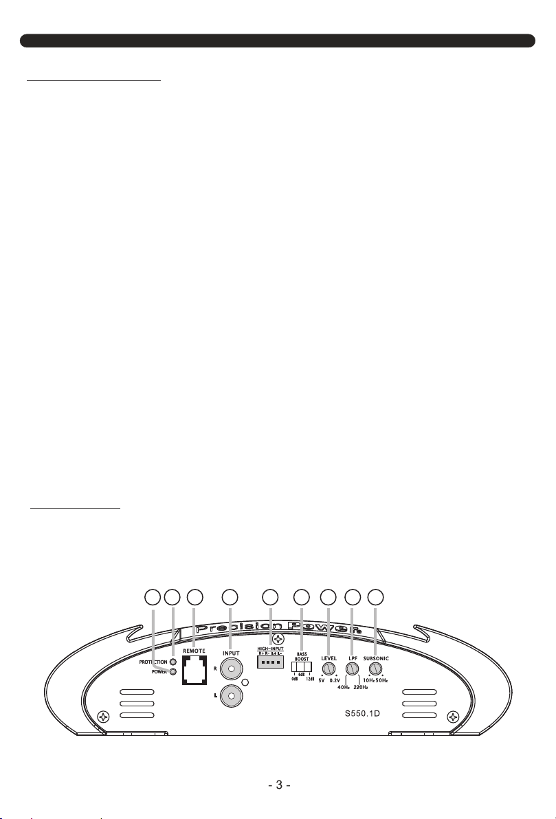
PANEL LAYOUT
Fig 1. S550 .1 D/S850. 1D /S1300.1D /S2000.1D P anel layout
13 10
12
7 11
865
9
Page 5

PANEL LAYOUT
1 2 3 4
INSTALLATION PRECAUTIONS
Before you i ns tall t he amp lifier, i nvestig at e yo ur car's layou t very careful ly. Take sp ecial
care w hen yo u wo rk n ea r th e gas tank, fuel lines , hydr aulic lines and electrica l wiri ng. Befo re
making or breakin g po wer connectio ns i n yo ur s ys tem, discon ne ct t he vehicle ba tt ery.
Confirm that yo ur head unit or other eq ui pment is turn ed off while conne cting the input ja cks
and s peaker ter minals. If you n eed t o replac e the power fu se, r eplace it only with a fuse
identical to that sugge sted b y th is m an ual. Using a f use of a different type or rating may result
in damage to yo ur audio syst em or your ampl ifier which i s not covered b y warranty .
MOUNTING AMPLIFIER
1. Pl an th e i nstallati on of the amplifi er s and find a s uitable lo cation with suffi ci ent air
circulati on.
2. Check th e dr awing below t o mount the bot tom amplifi er.
Page 6

MODEL S2000.1D S1300.1D S850.1D S550.1D
CABLE 2-4# 4# 4-6# 4-6#
FUSE 200A 120A 80A 60A
Fig 2. Mount bo ttom amplif ier
CONNECTING THE AMPLIFIER
1. Select cab le and fuse acc ording to the f ollowing ta ble.
2. Connect the amplifi ers ground c able to a close, ba re me tal part of the frame or
chassis. U se a nut an d bolt , NOT a s crew! Th e grou nd cab le must be at lea st the same s ize
as the +12vol t cable.
3. Connect th e re mote termin al to remot e ou tput of the head un it using 16 gauge (or
heavier) wi re.
4. Connect the fuse holder within 18”(45c m) of th e car batter y, an d run the s elected
cable from th is fuse to th e am plifier.
5. Connect all the i np uts with h igh-quali ty cables. C onnect Rem ot e Control if
necessary.
6. Insert f us e(s) into t he b attery fu se h older(s).
7. If using a subwoo fe r for 2-CH an d 4- CH, bridg e th e channel s by u sing the Le ft “ +”
and the Right “ -“ terminal s.
Page 7

WIRING DIAGRAM
Fig 3. Mono a mp lifier wi ri ng
(1 woofer loa d)
RCA signal
Source Unit
REMOTE signal
FUSE
Page 8

Fig 4. Mono a mp lifier wiri ng
(High level i nput mode)
nal
A sig
RC
Source Unit
FUSE
ON/OFF
control signal
Page 9

WIRING DIAGRAM
Fig 5. Mono a mp lifier wiri ng
(multi woof ers)
RCA signal
Source Unit
REMOTE signal
*Equi valen t paral lel w oofer l oad can not be
less th an the mi nimum l oad r ating . The 2
negat ive ter minal s are p arall eled in side th e
ampli fiers , as are th e 2 pos itive t ermin als.
These a re mono block a mpl ifier s, not mu ltichann el ampl ifier s.
FUSE
Page 10

TROUBLE SHOOTI NG
Symptom Possible Remedy
Amplifier
Check to make sure you have a good ground connection.
Protection
Check for short circuits on speaker leads.
No output Check that the RCA audio cables are plugged into the proper inputs.
Low output Reset the level Control.
High hiss in
Check the RCA cable is not shorted to power ground at amplifier side.
Check that the Input level control is set to match the signal level of the head
Amplifier gets
Check that the minimum load impedance for the amplifier model is correct.
will not
power up
LED Comes on
The speakers
Distorted sound
Very hot
Check that there is battery power on the (+)terminal .
Check all fuses, replace if necessary .
Make sure that the Protection LED is not illuminated.
Check the speaker load not beyond the minimum load.
Remove speaker lead, and reset the amplifier. If the protection LED still
Comes on, then the amplifier is faulty and needs servicing .
Check all speakers wiring.
Check the headunit output and the amplifier level setting.
Check the Crossover Control settings.
Check the amplifier grounding.
unit. Always try to set the Input level as low as possible.
Check that all crossover frequencies are properly set.
Check for short circuits on the speaker leads.
Check that there is good air circulation around the amplifier. In some
applications, It may be necessary to add an external cooling fan.
Page 11

SPECI FICATIONS
Model S550.1D S850.1D PX1.1300D PX1.2000D
1Ohm Load 550W x 1 850W x 1 1300W x 1 2000W x 1
2Ohm Load 400W x 1 600W x 1 900W x 1 1300W x 1
4Ohm Load 240W x 1 350W x 1 520W x 1 750W x 1
Bridged 4Ohm Load N/A N/A N/A N/A
Input Level
High l evel i nput
Frequency Response
X-over Type
LPF
Subsonic / HPF
Bas s Boost Frequency
Bas s Boost Level
THD
Dampi ng Factor
S/N Ratio
Minimum Load 0.5 Ohm
Voltage Protection
Components & PCB
Bas s Remote
Height
Width
Length
305mm/ 12.01" 345mm/ 13.58" 415mm/ 16.34" 485mm/ 19.09"
40Hz - 220Hz
10Hz - 50Hz
10Hz - 220Hz
LPF/Subsonic
RMS power at 14.4V
Features
0.2~5V
Yes
>85dB
1 Ohm
<0.5%
>200
55Hz
0dB - 6dB - 12dB
DIMENSION
59mm/2.32"
240mm/ 9.45"
<8.4V & >16V
Yes
Page 12

 Loading...