

Page 1

LIMITED 90-DAY CONSUMER WARRANTY
LIMITED TWO-YEAR CONSUMER WARRANTY WITH PURCHASE AND INSTALLATION BY A
PRECISION POWER AUTHORIZED DEALER
Precision Power promises to the original purchaser, to repair or replace this product with a new or
refurbished unit (at Precision Power’s sole and absolute discretion) should it prove to be defective in
workmanship or material under normal use, for a period of *two-years from the date of purchase
from the Precision Power authorized dealer, PROVIDED the product was purchased and installed
by a Precision Power authorized dealer. During this *two-year period, there will be no charge for
product repair or replacement, PROVIDED the unit is returned to Precision Power, return shipping
pre-paid, along with the required proof of installation, the bill of sale or other dated proof of purchase, and the consumer’s contact information.
If the unit is installed by anyone other than a Precision Power authorized dealer, the warranty period
will be 90-days from the date of purchase. This warranty is non-transferable and does not apply to
any unit that has been modified or used in a manner contrary to its intended purpose, and does not
cover damage to the unit caused by installation or removal of the unit. During this 90-day period,
there will be no charge for the repair or replacement PROVIDED the unit is returned to Precision
Power, return shipping prepaid, along with the bill of sale or other dated proof of purchase and the
consumer’s contact information.
This warranty is void if the product has been damaged by accident or unreasonable use, neglect,
improper service or other causes not arising out of defects in materials or construction. This warranty does not cover the elimination of externally generated static or noise, or the correction of antenna problems or weak reception, damage to speakers, accessories, electrical systems, cosmetic
damage or damage due to negligence, misuse, failure to follow operating instructions, accidental
spills or customer applied cleaners, damage due to environmental causes such as floods, airborne
fallout, chemicals, salt, hail, lightning or extreme temperatures, damage due to accidents, road hazards, fire, theft, loss or vandalism, damage due to improper connection to equipment of another
manufacturer, modification of existing equipment, or Product which has been opened or tampered
for any reason. Units which are found to be damaged by abuse resulting in thermally damaged
voice coils are not covered by this warranty but may be replaced at the absolute and sole discretion
of Precision Power. Unit must be returned to Precision Power, postage pre-paid, with bill of sale or
other dated proof of purchase bearing the following information: consumer's name, telephone number, and address, authorized dealer's name and address, and product description. Please contact
Precision Power warranty office at 800-724-1377 or repairs@precisionpower.com to obtain a
Return Authorization number prior to shipping the product.
Note: This warranty does not cover labor costs for the removal and reinstallation of the unit. IN ORDER FOR THE TWO-YEAR WARRANTY TO BE VALID, YOUR UNIT MUST BE SHIPPED WITH
PROOF OF INSTALLATION BY A PRECISION POWER AUTHORIZED DEALER. ALL UNITS
RECEIVED BY PRECISION POWER FOR WARRANTY REPAIR WITHOUT PROOF OF PRECISION POWER AUTHORIZED DEALER INSTALLATION AND PURCHASE WILL BE COVERED
BY THE LIMITED 1 YEAR WARRANTY.
BY PURCHASING THIS PRODUCT, ALL WARRANTIES INCLUDING BUT NOT LIMITED TO
EXPRESS WARRANTY, IMPLIED WARRANTY, WARRANTY OF MERCHANTABILITY, FITNESS
FOR PARTICULAR PURPOSE, AND WARRANTY OF NON-INFRINGEMENT OF INTELLECTUAL PROPERTY ARE EXPRESSLY EXCLUDED TO THE MAXIMUM EXTENT ALLOWED BY
LAW, AND PRECISION POWER NEITHER ASSUMES NOR AUTHORIZES ANY PERSON TO
ASSUME FOR IT ANY LIABILITY IN CONNECTION WITH THE SALE OF THE PRODUCT. PRECISION POWER HAS ABSOLUTELY NO LIABILITY FOR ANY AND ALL ACTS OF THIRD PARTIES INCLUDING ITS AUTHORIZED DEALERS OR INSTALLERS. BY PURCHASING THIS
PRODUCT, THE CONSUMER AGREES AND CONSENTS THAT ALL DISPUTES BETWEEN
THE CONSUMER AND PRECISION POWER SHALL BE RESOLVED IN ACCORDANCE WITH
CALIFORNIA LAWS IN LOS ANGELES COUNTY, CALIFORNIA. Some states do not allow limita-
tion on how long an implied warranty lasts. In such states, the limitation or exclusions of this Limited
Warranty may not apply. Some states do not allow the exclusion or limitation of incidental or consequential damages. In such states, the exclusion or limitation of this Limited Warranty may not apply
to you. This Limited Warranty gives you specific legal rights, and you may have other rights which
vary from state to state.
2010 Sedona Series
Components
S2.65C
You’re smart enough to buy these Sedona Series Components,
be smart enough to read this manual…
Page 2
Contents
Introduction………………………………………...3
Practice Safe Sound!
What’s In the Box
Installation………………………………………….4
Tools of the Trade
Speaker Mounting Locations
Door Mounting……………………………………..5
Rear Deck Mounting
Installing the Mid-bass
Installing the Mid-bass (cont.)……………………6
Surface Mounting the Tweeter…………………...7
Flush Mounting the Tweeter, Fixed Panel………8
Flush Mounting the Tweeter, Removable……….9
Installing the Crossover…………………………10
Crossover Wiring Diagram………………………11
Limited Consumer Warranty…………………….12
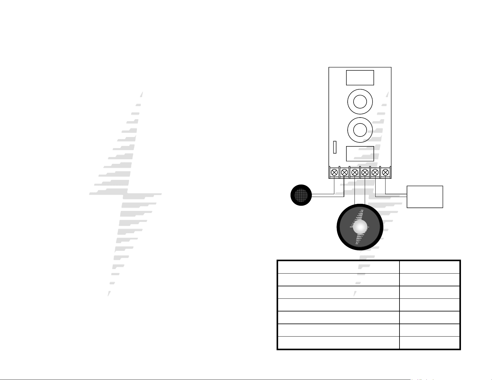
SEDONA PASSIVE CROSSOVER (COVERS REMOVED)
WIRING DIAGRAM
TW- TW+ W- W+ IN- IN+
Radio or
Amplifier
Nominal Impedance 4 Ohm
Power Handling (continuous/peak) 100w
Frequency Response 70-20kHz
Sensitivity (1w/1m) 92db
Woofer Mounting Depth 2.25” (2 1/4”)
Woofer Mounting Diameter 5.625” (5 5/8”)
Tweeter Mounting Depth .875” (7/8”)
Page 3

INSTALLING THE CROSSOVER
Step 1: Find a location for the crossover away from any fac-
tory or aftermarket electrical wires. It is recommended to
mount the passive crossover close to the amplifier.
Step 2: Remove top cover of crossover housing. Don’t lose it.
Step 3: Mark the mounting holes with a marking pen.
Step 4: Remove crossover and pre-drill mounting holes using
a 1/8” drill bit.
WARNING: Window mechanisms, electrical wires, and
other expensive car parts have a nasty habit of hiding
where you least expect. CHECK BEFORE YOU DRILL!
Step 5: Mount the crossover using the supplied #8 screws.
Step 6: There are two sets of connections on the crossover.
The input terminals (IN) should be connected to the source
(radio or amplifier). The woofer terminals (W) should be connected to the midrange speaker. The tweeter terminals (TW)
should be connected to the tweeter. Be sure to observe the
correct polarity. Changing the polarity of the tweeter may be
necessary for optimum sound quality.
Step 7: Re-install the crossover cover.
INTRODUCTION
Thank you for your purchase of this Sedona Series Compo-
nent Loudspeaker System from PrecisionPower™. Our engineers have combined state of the art materials such as
formed prolypropylene cones and mylar dome tweeters with
cutting edge industrial design to achieve competition-ready
performance levels.
PRACTICE SAFE SOUND!
Continuous exposure to sound pressure levels over 100dB
may cause permanent hearing loss. High power automotive
sound systems can generate sound pressure levels in excess
of 130dB. When playing your system at high levels, please
use hearing protection and prevent long term exposure.
WHAT’S IN THE BOX
Your new Sedona Series component speaker kit includes all
the necessary mounting hardware and cables for a basic installation:
Quantity Description
1 Installation and Operation Manual
2 Mylar Tweeters
2 Tweeter flush mount hardware kits
2 Tweeter surface mount hardware kits
2 Component woofers
2 Passive crossovers
4 Speaker cables (speakers to crossover)
2 Grilles
Page 4

INSTALLATION
The performance of your new PrecisionPower Component
Loudspeaker system is directly proportional to the quality of
installation. Care taken during the installation process will be
rewarded with years of satisfying performance. If you are unsure about your installation capabilities, please refer to your
local Authorized PrecisionPower Dealer for technical assistance. If you decide to install the speaker system yourself,
please read the entire owner’s guide before beginning your
installation.
TOOLS OF THE TRADE
Listed below are tools you may wish to have on hand before
starting your installation. Having the proper tools will make the
installation much easier. Some of these tools are necessities,
some will just make the job easier.
• Marking Pen • Phillips Screwdriver
• Electric Drill • Volt/Ohm Meter (Optional)
• 1/4" Drill Bit • Assorted Tin Snips
• 1/8" Drill Bit • Wire Cutters
• 3/8" Drill Bit • Wire Crimpers
• Hole Saw Arbor • Wire Strippers
• 4¾" Hole Saw (5¼” woofer install.) • Razor Knife (Optional)
• 5¾" Hole Saw (6½" woofer install.)
• 1¾" Hole Saw (for flush mount tweeter install.)
FINDING SPEAKER MOUNTING LOCATIONS
Choosing the correct speaker locations can have a significant
effect on the sound quality of the system. There are many different considerations for choosing the locations that best suit
your needs. The locations must be large enough for the
speakers to fit without interfering with other vehicle parts such
as window mechanisms, etc. Care is needed to ensure that
the location you have chosen will not affect any of the mechanical or electrical operations of the vehicle. If minimal intrusion in your vehicle is desired, factory speaker locations may
be the ticket for you. Placing the speaker in the factory location can often give you very desirable results. Alternative locations to consider include mounting in customized kick panels,
rear decks, or side panels.
FLUSH MOUNTING THE TWEETER
FIXED PANELS
Step 1: Determine the tweeter mounting location, then route
the wires from the crossover to the tweeter location.
Step 2: Mark the center point of the tweeter location.
Step 3: If using a hole saw, first drill a pilot hole, then cut out
the hole using a standard 2-1/8" hole saw.
Step 4: If not using a hole saw, use either the cardboard
packaging for the tweeters or the surface mount trim ring as a
template to mark the proper size hole. Cut out the hole.
Step 5: Remove the tweeter from the flush mount housing
and insert the proper length machine bolt through the center
hole of the housing.
Step 6: Connect the speaker wires observing the correct polarity.
Step 7: Screw the bolts in until the tweeter housing is firmly
mounted to the panel. (Make sure the arrow at the rear of the
tweeter housing is pointing in the desired direction.)
Step 8: Insert the tweeter into the housing and attach trim
ring.
Page 5

FLUSH MOUNTING THE TWEETER
REMOVABLE PANELS
Step 1: Determine the tweeter mounting location, then route
the wires from the crossover to the tweeter location.
Step 2: Mark the center point of the tweeter location.
Step 3: If using a hole saw, first drill a pilot hole, then cut out
the hole using a standard 2-1/8" hole saw.
Step 4: If not using a hole saw, use either the cardboard
packaging for the tweeters or the surface mount trim ring as a
template to mark the proper size hole. Cut out the hole.
Step 5: With the tweeter assembled, route the wires through
the hole and the pressure ring and slip the pressure ring over
the tweeter assembly.
Step 6: Align the tweeter so the logo faces the desired direction then push the pressure ring on to the rear of the tweeter
assembly until the tweeter is snugly mounted to the panel.
Step 7: Connect the speaker wires observing the correct polarity and re-assemble the panel.
DOOR MOUNTING
When considering possible speaker locations in the doors, be
sure to check the operation of the window mechanism and all
other moving parts inside the door. Most vehicles use a stabilizer stop bar in between the door and the door jamb. This
bar prevents the door from opening too far, but may intrude
into the speaker mounting area when the door is closed.
Many do-it-yourself installers overlook this and check for
speaker clearance only when the door is fully open.
REAR DECK MOUNTING
In rear deck installations, check the operation of the trunk
suspension springs or tension bars. These tension bars can
move when opening and closing the trunk and can exert a
great deal of force against anything that obstructs their movement, such as a speaker basket or motor assembly. In addition, try to avoid locating the speakers too close to the back
edge of the rear deck. Installing the rearmost screws may not
be possible without the removal of the rear window.
INSTALLING THE MID-BASS
Step 1: Determine where the speaker will be mounted. Make
sure there is a flat area large enough for the speaker to fit
properly. An uneven mounting surface can damage the driver
and limit the bass performance of your Sedona Series component system.
Step 2: Check to make sure the mounting location you have
chosen for the speaker will not interfere with the operation of
the vehicle.
Step 3: Using the supplied template guide, mark the hole
with a pen. [Skip this step if using correctly sized factory locations]
Page 6

Step 4: [Skip this step if using correctly sized factory locations] Cut the hole for the speaker. A hole can be cut either
with a pair of metal tin snips, an air or jig saw, or with a hole
saw corresponding to the size of the woofer listed below.
• 5 5/8” Hole Saw (6½” woofer installation)
WARNING: Window mechanisms and electrical wires and
other expensive car parts have a nasty habit of hiding
where you least expect. CHECK BEFORE YOU DRILL!
Step 5: Run the speaker wire to the speakers. Make sure to
keep wires away from sharp metal or other edges. When
passing through metal, use a protective grommet.
Step 6: Turn the speaker backwards against the surface &
mark the mounting holes with a pen.
Step 7: Pre-drill mounting holes using a 1/8" drill bit.
WARNING: Window mechanisms and electrical wires and
other expensive car parts have a nasty habit of hiding
where you least expect. CHECK BEFORE YOU DRILL!
Step 8: Pull the wire through the speaker opening and con-
nect to the speaker. Be sure to observe proper midrange polarity during this process.
Step 9: To mount the speaker, the speaker is placed through
the grille ring from the front. Place the speaker and the grille
ring in the installation hole. Align the mounting screw holes
and drive in the four mounting screws. Push the perforated
metal grille back into the grille ring.
SURFACE MOUNTING THE TWEETER
Step 1: Determine the tweeter mounting location, then route
the wires from the crossover to the tweeter location.
Step 2: Place the surface mount housing against the panel
and mark the two holes at the rear of the housing.
Step 3: Drill the smaller center hole using a 1/8" drill bit. This
is the mounting screw hole.
Step 4: Drill the larger off-center hole using a 3/8" drill bit, in-
sert a grommet and route the speaker wire from the crossover through the grommet.
Step 5: After removing the surface mount tweeter assembly
trim ring, route the tweeter wires through the larger hole in
the housing and connect to the speaker wires from the
crossover.
Step 6: Insert the excess speaker wire into the hole and position the housing so the housing will not pinch the wires after
final mounting.
Step 7: Attach the housing using the supplied screws of the
correct length for a solid mount.
Step 8: Insert the tweeter into the housing and attach the trim
ring.
 Loading...