

Page 1

TM
CONTENTS
(click on a topic to view)
Congratulations Functions
Features and Specifications Maximizing Performance
Installation Maximizing Performance
Installation Troubleshooting
Wiring System Diagram 1
Wiring Block Diagram
Functions Warranty
PSC 221 Phase Shifter OWNERS MANUAL POWER CLASS
Page 2
Congratulations and thank you.....
for choosing
proudly design, engineer and manufacture audio products at our facility in
Phoenix, Arizona. Our award winning engineering team utilizes innovative
technology to consistently deliver Absolutely State of the Art
sound quality, reliability, and value. This
our commitment to offer you unparalleled versatility and quality for years of
dependable service and listening enjoyment.
PrecisionPower
audio epuipment. At
PrecisionPower
PrecisionPower
TM
performance,
product reflects
we
S er vice
Do not attempt to service
Performing exploratory surgery on your audio equipment yourself
will void the warranty. Many parts of your
are custom built to our specifications. Our factory parts are not
made available to anyone else nor are they for sale. Our goal
is to make sure that your
sound as good as the day it was purchased. Contact your
authorized
service through
PrecisionPower
PrecisionPower
PrecisionPower
PrecisionPower
dealer about obtaining any warranty
.(See Warranty insde back cover)
products yourself.
PrecisionPower
product will always
gear
FOR YOUR RECORDS:
Model
Serial Number
Purchase Date
Caution!
The extended use of a high powered audio system may
result in hearing loss or damage. While
systems are capable of
incredible accuracy, they are also designed for you to
enjoy at more reasonable levels all of the sonic subtleties
created by musicians. Please observe all local sound
ordinances.
"Concert Level"
PrecisionPower
volumes with
BA CK TO CONTENTS
Page 3

FEATURES / SPECIFICATIONS
Adjustable left and right channel phase shift control
Phase control ByPass switch
Left and right 180 phase shift switch
Gold-plated RCA input and output connectors
PWM Power Supply
Remote turn-on capability
L.E.D. power indicator
Designed and Handcrafted in the U.S.A.
Specifications
Signal-to-Noise Ratio >102 dB
Total Harmonic Distortion (1KHz) 0.002%
Input Impedance 10k Ohms
Input/Output Gain Unity
Maximum Input Voltage 8VRMS
Maximum Output (10 KΩ Load) 8VRMS
Supply Voltage 11-15 VDC
1
BA CK TO CONTENTS
Page 4
Placement
The
basic objectives:
1) Make the subwoofer sound like it’s in the front of the car
(even when the subwoofer is in the back of the car).
2) Raise the perceived soundstage to ear level and solidify
the center image (even when your front speakers are
closer to your feet).
Both objectives are accomplished by shifting the signal
phase, primarily in the lower midrange frequencies,
resulting in arrival time corrections to the sound from your
front speakers. In a typical autosound system, the signal
path is divided into different frequency ranges (subwoofer,
midrange, etc.) as well as locations (front and rear). For
best results, localizing your subwoofer to the front, you
will need an active crossover sending only subwoofer
frequencies to the amplifier running your subwoofers.
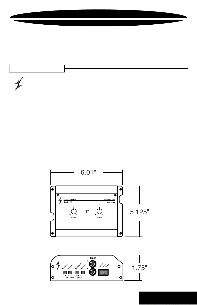
INSTALLATION / MOUNTING
PSC-221
has been designed to accomplish two
If your system is: Insert the
When placing your phase shifter:
PSC-221
in front of:
4 way The midbass amp
3 way The midrange amp
2 way The full range/highpass amp
Note: The PSC-221 will not improve your front stage if it is
controlling only the rear speakers.
2
BA CK TO CONTENTS
Page 5
INSTALLATION / MOUNTING
NOTE:
Before beginning, disconnect the negative (-) terminal of the battery
to prevent an electrical short to ground. Reconnect the negative
terminal only after all connections have been made.
Mounting
To prevent damage to the Phase Shifter while driving,
mount it in a secure place. Choosing the appropriate
location will depend upon your vehicle and the complexity of
your system design. Typical mounting locations would be in
the same location as your amplifiers and or crossovers.
Never mount the component in a location that would subject
it to immersion or exposure to water.
Once a location has been chosen, securely mount the
PSC-221
using the four screws supplied. Be Careful!
Inspect the area underneath to be sure you are not drilling
into wires, brake or fuel lines, etc. that could be damaged by
the drill bit or screws.
3
BA CK TO CONTENTS
Page 6

WIRING
eject
123
4
Trk 1
5
876
BASS
TREBLE
MARKET
PPI
INGDPT
BALANCE
TRACK
VOLUME
RIGHT
FOWARD
REVERSE
LEFT
NOTE:
Before beginning, disconnect the negative (-) terminal of
the battery prior to working on the positive (+) terminal to
prevent a short to ground. This is important, unless you want
to spend the rest of your life with a nickname like "Sparky,"
or "Smokey ." Reconnect the negative terminal onl y after all
connections have been made.
4
BA CK TO CONTENTS
Page 7

WIRING
WIRING
The next step is to connect the Power , Ground, and Remote wires to
your
PSC-221
. The power wire should run from the mounting location
through the vehicle to the battery or power distribution block. Avoid
sharp corners, creases, and sharp body parts. When passing through
any metal wall (i.e. firewall etc.), a grommet must be used to prevent
the wire from chaffing and shorting to ground.
The ground wire should be of the same gauge as the power wire. As
a rule of thumb, use as short a length of wire as possible.
Find a location near the
PSC-221
that is metal (the floor is ideal) and
clean an area about the size of a quarter to bare metal. Drill a pilot
hole in the middle of this area. Be Careful! Inspect the area underneath
to be sure you are not drilling into wires, brake or fuel lines, etc.
Terminate the wire with a ring connector and attach it to the bare
metal using a #8 sheet metal screw and washer (not supplied). We
suggest crimping and/or soldering this connection. After the connection
is complete, coat the area with silicone or some similar material to
prevent rust from developing.
Powerlock
Finally, the remote wire needs to
run to the power antenna (or
amplifier remote) lead of the head
unit. This wire supplies a 12 volt
signal to the Phase Shifter when
T/O
B+
the main system is activated.
Once you have routed the power ,
ground, and remote wires through
the vehicle, it is time to connect the wires to the
PSC-221
. Be sure
that you have not reconnected the ground cable to the negative post
of the battery.
Cut off excess wire and, using wire strippers, strip the power, ground
and remote cables about 1/8 inch. Locate the power, ground, and
remote
Powerlock
connector (supplied). On the top of the connector
are three slotted screws. With a small flat-bladed screwdriver , loosen
the screws before attempting to insert the cables. After you have
inserted the stripped end of each cable into the connector, secure it
by tightening the associated screw. Check that each connection is
tight. If the wires are secure, the connector may be plugged into the
PSC-221
. 5
BA CK TO CONTENTS
Page 8

FUNCTIONS
Bypass Switch: Gives you the ability to switch from the unadjusted
system to the phase corrected system for easy comparision
Phase Invert Switch: Gives you the ability to invert the signal.
Left and right channels can be seperately inverted.
RCA Inputs: Connect the RCA cables from the head unit, preamplifier ,
or another processor here.
Power Connector: Connect Ground, Remote turn on and Power wires
to the
Powerlock
connector and plug it in here
6
BA CK TO CONTENTS
Page 9

FUNCTIONS
RCA Outputs: Connect RCA cables from the
amplifier
Phase Controls: Use these two controls to adjust the amount of
phase shift for left and right channels.
PSC-221
to the
7
BA CK TO CONTENTS
Page 10

Adjustments
To make the adjustments easier , it is recommended that
you create a temporary extension cable for the power,
ground, remote and preamp cables that will allow you to
extend the
you to make adjustments while listening to the system.
For a starting point, set both the left and right phase
controls to the fully clockwise position, the phase invert
switches to the out position and the ByPass button to
the out position.
Choose a selection of music that has a clearly defined
vocal and acoustic track. This will be very helpful in
placing the center image where you want it to be.
Listen to the music you have selected for a few moments
prior to making any adjustments. Pay close attention to
the location of the individual instruments and the vocalist.
Once you have a good feel for their locations throughout
the stage begin making adjustments by moving the right
and left phase controls in unison. Start from the far right
(or clockwise position), sweep both controls from right to
left listening for an improvement in the bass location.
You want the bass to become localized up front.
If you still can’t localize the sub bass up front you may
need to reverse the phase invert switches on the
endplate.
Once you have the sub base up front, continue making
small adjustments of both phase controls. Move the
detented controls together, but in opposited directions
one position at a time, until you have achieved the desired
stage for your system. Remember , this adjustment is very
subjective and will take time to achieve the correct
combinations of settings for your particular system. Listen
to several tracks now, and check your progress using
the bypass switches.
MAXIMIZING PERFORMANCE
PSC-221
WIRING
to the drivers seat. This will enable
8
BA CK TO CONTENTS
Page 11

MAXIMIZING PERFORMANCE
These illustrations show the effect the phase shift controller has
on your perception of the sound stage “image” as you adjust
each control.
NOTE:
It is important to remember that both controls should
be moved in unison but in opposite directions after
you have achieved your star ting image so you don’t
lose the up front sub stage you have acquired in
your initial adjustments.
9
BA CK TO CONTENTS
Page 12

NO SOUND
TROUBLE SHOOTING
Is the LED lit?
YES
Check Input cables for signal by
connecting them straight to the
amplifier
ANY SOUND NOW?
YES
Problem is in the
local Authorized
Dealer or call 1-800-62POWER.
SOUND IN ONE CHANNEL ONLY
Reverse left and right RCA outputs.
OPPOSITE CHANNEL
Reverse RCA inputs
OPPOSITE CHANNEL
Reverse RCAs at head unit
(Check Balance control)
PSC-221
.See your
PrecisionPower
SOUND IS NOW IN
SOUND IS NOW IN
NO
Check Power and Remote turn-on wire
for voltage. Make sure Ground wire is
secure.
NO
Problem is elsewhere in the system.
Check head unit and amplifiers.
SAME CHANNEL
Problem is in the amplifier, speakers or
associated wiring of the silent channel.
SAME CHANNEL
Problem is in the
local Authorized
Dealer or call 1-800-62
PSC-221
. See your
PrecisionPower
POWER
.
OPPOSITE CHANNEL
Problem is in the head unit
SOUND IS NOW IN
SAME CHANNEL
Problem is in the RCA cables
10
BA CK TO CONTENTS
Page 13

SYSTEM ONE
Power
In-Clip
o
-ø
11
BA CK TO CONTENTS
Page 14

BLOCK DIAGRAM
12
BA CK TO CONTENTS
Page 15

WARRANTY
Three-Year Limited U.S.A. Warranty
This warranty gives you specific legal rights, and you may also have other rights which vary from
state to state.
workmanship under normal use and service for a period of three (3) years from the date of
original purchase when the unit is installed by an Authorized Dealer. Non-Authorized Dealer
installed products carry a one (1) year parts and ninety (90) days labor limited warranty. The
extent and conditions of Limited Warranty are as follows:
1. Authorized Dealer Installed Products:
to the original purchaser, any unit which
and under warranty, provided the defect occurs within three (3) years from the date of original
purchase when the unit is installed by an Authorized Dealer and the product is returned immediately to
2. Non-Authorized Dealer Installed Products:
charge, to the original purchaser, any unit which
defective and under warranty, provided the defect occurs within ninety (90) days from the date of
purchase and the product is returned immediately to
ninety (90) days for Non-Authorized Dealer Installed Products will be for parts only and will
extend for one (1) year from the date of purchase. This warranty is not transferable.
3. The date of purchase and proof of Authorized Dealer Installation of a PrecisionPower product
must be established by an original sales receipt which must accompany the article being returned for warranty work.
4. This warranty shall NOT apply to any
tory serial number removed or defaced. All products received (by
ranty or out of warranty repair, with their original serial numbers removed or defaced, will NOT be
repaired and will be returned to sender, freight collect. Refer to original packaging for the serial
number of your component speakers.
5. The provisions of this warranty shall not apply to any
purpose for which it is not designed, which has been repaired or altered in any way, or which has
been connected, installed, or adjusted other than in accordance with the instructions furnished in
PrecisionPower’ s
subject to misuse, neglect, or accident.
6. PrecisionPower does not authorize any other persons to assume any other liability in connection with its products. THIS WARRANTY IS THE ONLY EXPRESS WARRANTY MADE BY
PRECISIONPOWER APPLICABLE T O ITS PRODUCTS. ANY IMPLIED WARRANTY OR MERCHANTABILITY OR FITNESS FOR A PARTICULAR PURPOSE APPLICABLE TO
PRECISIONPOWER PRODUCTS IS LIMITED IN DURATION TO THE DURATION OF THIS
LIMITED WARRANTY. PRECISIONPOWER SHALL NOT BE LIABLE FOR THE INCIDENTAL,
CONSEQUENTIAL, OR COMMERCIAL DAMAGES RESUL TING FROM THE BREACH OF THIS
WRITTEN WARRANTY. Some states or provinces do not allow the exclusion or limitation of
incidental or consequential damages or limitations on how long an implied warranty lasts; so the
above limitations or exclusions may not apply to you.
7. Y our product will be serviced on an in-warranty basis within the warranty period for the correction of warranted defects. If improper operation of your
contact your Authorized Dealer for assistance with the return and factory repair of your
PrecisionPower
product. If an Authorized Dealer is not available, return the unit including your name, telephone
number, return address, a copy of your sales receipt, and a description of the problem to:
TO RETURN PRECISIONPOWER PRODUCTS OUT OF WARRANTY: Return the unit, postage
prepaid, in the original protective carton. Please include a description of the problem and, if
desired, a request for an estimate of repair costs. Unless a request for an estimate is included,
the unit will be repaired as necessary. Please contact
800-62-POWER for questions concerning out of warranty repair charges. Repaired unit will be
returned with an itemized statement, C.O.D.
PrecisionPower
PrecisionPower
owner’s manual. Nor shall this warranty apply to any part which has been
warrants its products to be free from defects in materials and
PrecisionPower
PrecisionPower’ s
. This warranty is not transferable.
PrecisionPower
PrecisionPower
PrecisionPower,Inc.
Service Department
4829 S. 38th Street
Phoenix, AZ 85040-2964
will either repair or replace at no charge,
examination discloses to be defective
PrecisionPower’s
PrecisionPower
will either repair or replace at no
examination discloses to be
. Warranty claims beyond
product found to have the original fac-
PrecisionPower
PrecisionPower
PrecisionPower
PrecisionPower
product should occur,
Customer Service at 1-
product used for a
BA CK TO CONTENTS
) for in war-
 Loading...