

Page 1
Thank you for choosing
PPI
audio epuipment. Now, HANG ON!
PPI
products are engineered and manufactured to deliver a wild ride of
performance, sound quality, and reliability. This
PPI
product reflects our
commitment to offer you versatility and quality for years of incredible power
and listening enjoyment!
SERVICE
Do not attempt to service
PPI
products yourself. Performing exploratory
surgery on your audio equipment yourself will void the warranty. All parts of
your
PPI
gear have been built to our specifications. These parts are not
made available to any unauthorized
PPI
dealer nor are they for sale. Our
goal is to make sure that your
PPI
product will always perform as good as
the day it was purchased. Contact your authorized
PPI
dealer about obtain-
ing any warranty service through
PPI
. (See Warranty inside back cover.)
CAUTION!
The extended use of a high powered audio system may result in hearing loss
or damage. While
PPI
systems are capable of "Concert Level" volumes,
they are also designed for you to enjoy at more reasonable levels all of the
creative expressions made by musicians. Please stay seated while driving
and observe all local sound ordinances.
Page 2
1
4-Way/5-Way Variable Crossover with RCA Outputs
QBASS™
Bass Boost
Balanced Differential Input Circuit
Speaker Lead High Level Inputs
High Voltage Input Capability
Gold Plated RCA, Speaker and Power Connectors
Mixed Mono/Stereo Operation
PPI4240
. . . . . . . . . . . . . . . L: 285mm/11.22”
W: 256mm/10.08”
H: 62mm/2.44”
PPI5440
. . . . . . . . . . . . . . . L: 435mm/17.12”
W: 256mm/10.08”
H: 62mm/2.44”
Power Bandwidth:. . . . . . . . . . 7Hz to 80kHz
Signal to Noise Ratio: . . . . . . . 105 dB
Total Harmonic Distortion:. . . . .05%
Input Sensitivity: . . . . . . . . . . . 100mV to 12V
Input Impedance:. . . . . . . . . . 10k Ohms
Load Impedance (Stereo): . . . 2 Ohms to 8 Ohms
Load Impedance (Bridge): . . . 4 Ohms to 8 Ohms
Supply Voltage: . . . . . . . . . . . 10V to 15V
Damping Factor:. . . . . . . . . . . >300
Slew Rate: . . . . . . . . . . . . . . . >45V/µs
QBASS™
Equalization: . . . . . Up to +12db Boost @ 40Hz
Page 3
2
PPI4240
30W x 4 Channels @ 4 Ohms
60W x 4 Channels @ 2 Ohms
120W x 2 Channels @ 4 Ohms Bridged
PPI5440
30W x 4 Channels @ 4 Ohms
+ 120W x 1 Channel @ 4 Ohms
60W x 4 Channels @ 2 Ohms
+ 200W x 1 Channel @ 2 Ohms
120W x 2 Channels @ 4 Ohms Bridged
+ 120W x 1 Channel @ 4 Ohms
PPI4240
Front Variable 12db/Octave FULL/HPF/LPF 20-5kHz
Rear Variable 12db/Octave FULL/HPF/LPF 20-5kHz
Selectable FULL/HPF/LPF RCA Output
PPI5440
Front Variable 12db/Octave FULL/HPF/LPF 20-5kHz
Rear Variable 12db/Octave FULL/HPF/LPF 20-5kHz
Sub Variable 12db/Octave FULL/HPF/LPF 20-500Hz
PPI4240
Maximum Fuse Rating: 40 Amp (20 x 2)
PPI5440
Maximum Fuse Rating: 60 Amp (30 x 2)
Page 4
3
The following formula is a guide to determine current draw so you can
choose the proper gauge power cable and fuses for your system. A 50%
amplifier efficiency rating is used as an average.
(Total 4-Ohm rate RMS output x 2) x 2 = Total Input Wattage
Total Input Wattage/Supply Voltage = Current Draw (in Amps)
Example:
Your
PPI4240
is 30 watts x 4 RMS @ 4-Ohms.
You would use the formula below:
30 x 4 = 120 watts Total Output
120W x 2 = 240W Input/12.5v = 19.2 amps Current Draw
Note: Notice that the total power is multiplied by two. This compensates for
the 50% efficiency of the amplifier. When you drop your impedance in half
you double the amperage.
Total Current Draw Length of Wire to Run (in Feet)
(in Amps) <3 <7 <10 <13 <17 <20 <22 <28
0 - 20 14 12 12 10 10 8 8 8
20 -35 12 10 8 8 6 6 8 4
35 -50 10 8 8 6 6 4 4 4
50 - 65 8 8 6 4 4 4 4 2
65 - 85 6 6 4 4 2 2 2 0
85 - 105 6 6 4 2 2 2 2 0
105 - 125 4 4 4 2 2 0 0 0
125 - 150 2 2 2 2 0 0 0 0
Note: The ground wire should be the same size as the power wire.
Page 5
4
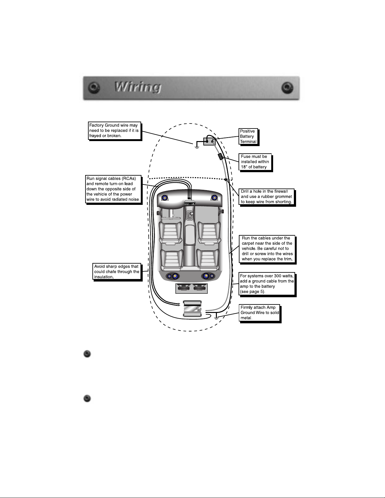
Before beginning, disconnect the negative (-) terminal of the battery prior
to working on the positive (+) terminal to prevent a short to ground.
This is important, unless you want to spend the rest of your life with a
nickname like "Sparky," or "Smokey." Reconnect the negative terminal
only after all connections have been made.
You will need to install an in-line fuse or circuit breaker in the power
wire within 18” of the batter y. This fuse or circuit breaker protects your
vehicle from fire in case the power wire shorts to the vehicle body.
Page 6

5
Remote Turn-on
Your head unit should have a lead marked ‘remote’ or ‘ power antenna’ which
will be used to turn on your amplifier. Extend this lead through your vehicle
along with your RCA signal wires. Strip 1/4 inch of the insulation off the wire
and insert the end into the corresponding terminal on the amplifier.
Grounding
Locate an area near the amplifier(s) that is metal and clean an area about the
size of a quarter to bare metal. Inspect the area around and underneath to
be sure you won't drill into wires, brake or fuel lines, etc. Drill a pilot hole in
the middle of this area. Terminate the ground wire with a ring connector and
attach it to the bare metal using a #8 sheet metal screw and washer or preferably , a bolt, nut and a star washer (not supplied). We suggest crimping and
soldering this connection. After the connection is complete, coat the area (on
both sides) with silicone or some similar material to prevent rust from developing on the bare metal.
If your grand total current draw is over 50 amps (or total output power is over
300 watts), you should run a ground wire beside your power wire from the
battery to the amplifier(s) in addition to your regular ground wire. Keep the
ground and power wires as close together as possible, and use the same
gauge wire for both. This will ensure that you have a good ground path, and
may eliminate such potential problems as engine noise and overheated
amplifiers.
Once you have run both the power and ground wires, it's time to connect the
cables to the amplifier. Cut off excess wire and, using wire strippers, strip the
ends of the power and ground cables approximately 1/4 inch. Locate the
power and ground connectors on the amplifier. With a small phillips head
screw driver, loosen the screws before to you insert the cables. Insert the
wires into the appropriate hole, and tighten the screws. The
Power/Ground/Remote will accommodate 8 gauge wire for the
PPI4240
and the
PPI5440.
Speaker Wires
Using 16 gauge or larger, run the speaker wires from the amplifier location
through the vehicle to the speakers. Observe the same precautions for
routing these wires that you followed for running the power and remote
turn-on wires. Cut off excess and, using wire strippers, strip 1/4 inch of
insulation. Loosen the four outer screws on the top of the connector. Insert
the speaker leads into the end. Check to be sure you've maintained proper
polarity before securing each wire, and tighten the screws on the amplifier.
Page 7
6
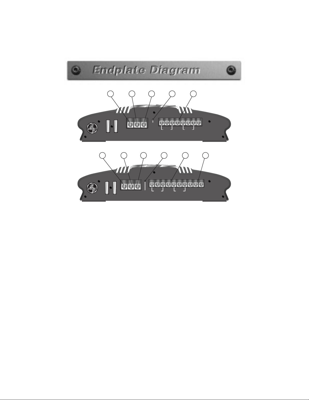
1. Battery Power
Connect the 12-volt constant power cable from the battery here.
2. Remote
Connect the remote turn on lead from you source unit here. This
connection will turn the amplifier on when the source unit is
powered up.
3. Ground
Connect your ground wire here. Make sure you use the same
gauge wire as your power cable.
4. Power LED
The LED will light up “GREEN” when the amplifier is powered on
and “RED” when it goes into protection.
5. Speaker Terminals
Insert your speaker cable here. Insert speaker wire into LEFT (+) and
RIGHT (-) for bridging.
6. Subwoofer Speaker Terminals
Insert the speaker cable for your subwoofer here.
FUSES
— 20 —
— 20 —
FUSES
REM GND+12V
POWER
BRIDGED
SPEAKER OUTPUT
PPI
4240
4
-channel
BRIDGED
RR
+RR -RL -FR +FR -FL + FL - RL +
(GREEN)
PROTECT
(RED)
POWER
FUSES
— 25 —
— 25 —
REM GND+12V
POWER
SPEAKER OUTPUT
PPI
5440
5
-channel
(GREEN)
PROTECT
(RED)
POWER
BRIDGED
BRIDGED
RR
+RR - SUB +SUB -RL -FR +FR -FL + FL - RL +
1 2 3 4 5 6
1 2 3 4 5
Page 8

7
All
PPI
amplifiers are capable of being bridged into a 4-Ohm mono output
without switches or bridging modules. This in turn allows you to run Full
range or component speakers and a subwoofer off one
PPI
amplifier. (using
passive crossovers)
You can achieve this mono channel by using the Left positive (+) speaker
connection and Right negative (-) speaker connection. You can bridge
channels 3 and 4, on your
PPI
four channel amplifiers, in the same way.
(Refer to the end panel drawing on page 8.)
Your new
PPI
amplifier offers you the flexibility of mixed mono operation.
This means you can operate each pair of channels in both stereo and mono
mode at the same time. This is accomplished by using highpass filters
(capacitors) on the higher frequency stereo channels, and a lowpass filter
(coil) on the subwoofers. The frequencies of the chosen highpass and lowpass filters must not overlap (allow the mids and highs to play the same
music as the subs) or the impedance the amplifier sees at those frequencies
will be cut in half possibly causing it to go into protection.
Page 9

8
1. Front RCA Input
Plug in the front RCA cables from the source unit or
PPI
signal
processor here.
2. Rear RCA Input
Plug in the rear RCA cables from the source unit or
PPI
signal
processor here.
3. RCA Outputs
Plug in the RCA cables here to send signal to a second amplifier. This
output can be Full Range, High Pass or Low Pass according to the
Output X-Over Switch.
4. Speaker Input
Plug in speaker cables here when RCA cables are not available.
5. Input -12db
Push this switch “IN” when using Speaker Inputs, or when RCA level
is over 5V.
6. Front Gain Control
Use this control to match the output level of the head unit to the
amplifier.
7. Front X-Over Freq
Select the front crossover frequency here. The detented control
moves clockwise from 20Hz to 5kHz. Use the chart on page 20
to select the desired crossover frequency.
8. QBASS™ Control
Select the desired boost for both Front and Rear Channels by turning
1 2 3 4 5 6 7 8 9 10
11 12 13 14 15
Page 10

9
9. Rear X-Over Freq
Select the rear crossover frequency here. The detented control moves
clockwise from 20Hz to 5kHz. Use the chart on page 20 to select the
desired crossover frequency.
10. Rear Gain Control
Use this control to match the output level of the head unit to the
amplifier.
11. Front X-Over Switch
Select the desired crossover setting, FULL/HPF/LPF for the front
speaker outputs.
12. Rear Input X-Over Switch
Select the desired crossover setting, FULL/HPF/LPF for the input
signal to the rear channel when using internal signal path vs.
RCA input.
13. Rear Input Inter nal/External Switch
Select “INT” position if you want to use the internal signal path from
the front crossover for the rear input, or the “EXT” position to use the
external rear RCA input.
14. Rear X-Over Input Switch
Select the desired crossover setting FULL/HPF/LPF for the rear
speaker output.
15. Output X-Over Switch
Select the desired crossover setting, FULL/HPF/LPF for the RCA
Page 11

10
1 2 3 4 5 6 7 8 9 10
14 15 16 17 18
11 12 13
19 20
1. Front RCA Input
Plug in the front RCA cables from the source unit or
PPI
signal
processor here.
2. Rear RCA Input
Plug in the rear RCA cables from the source unit or
PPI
signal
processor here.
3. Subwoofer RCA Input
Plug in the subwoofer RCA cables from the source unit or
PPI
signal
processor here.
4. Speaker Input
Plug in speaker cables here when RCA cables are not available.
5. Input -12db
Push this switch “IN” when using Speaker Inputs, or when RCA level
is over 5V.
6. Front Gain Control
Use this control to match the output level of the head unit to the
amplifier.
7. Front X-Over Freq
Select the front crossover frequency here. The detented control moves
clockwise from 20Hz to 5kHz.
8. QBASS™ Control
Select the desired boost for both Front and Rear Channels by turning
the control clockwise from 0-12dB.
Page 12

11
9. Rear X-Over Freq
Select the rear crossover frequency here. The detented control moves
clockwise from 20Hz to 5kHz.
10. Rear Gain Control
Use this control to match the output level of the head unit to the
amplifier.
11. Subwoofer X-Over Freq
Select the subwoofer crossover frequency here. The detented control
moves clockwise from 20Hz to 500Hz.
12. Subwoofer QBASS™ Control
Select the desired boost by turning the dial clockwise form 0-12dB
centered at 40Hz on the rear channel.
13. Subwoofer Gain Control
Use this control to match the output level of the head unit to the
amplifier.
14. Front X-Over Switch
Select the desired crossover setting, FULL/HPF/LPF for the front
speaker outputs.
15. Rear Input X-Over Switch
Select the desired crossover setting, FULL/HPF/LPF for the input
signal to the rear channel when using internal signal path vs. RCA input.
16. Rear Input Inter nal/External Switch
Select “INT” position if you want to use the internal signal path from
the front crossover for the rear input, or the “EXT” position to use the
rear RCA input.
17. Rear X-Over Switch
Select the desired crossover setting FULL/HPF/LPF for the rear
speaker output.
18. Sub Input X-Over Switch
Select the desired crossover setting, FULL/HPF/LPF for the output
signal of the rear channel when using internal signal path vs. RCA input.
19. Sub Input Inter nal/External Switch
Select “INT” position if you want to use the internal signal path from
the rear crossover for the sub input, or the “EXT” position to use the
external sub RCA input.
20. Sub X-Over Switch
Select the desired crossover setting, FULL/HPF/LPF for the RCA output.
Page 13

12
1. Adjust all amplifier input gain controls to just above minimum sensitivity
(fully counterclockwise).
2. Using the cleanest source (CD), with music playing turn up the head
unit until you can hear the music begin to distort. Now turn it down a
bit until you cannot hear the distortion.
3. Increase the Amplifier gain (clockwise) until the onset of audible
distortion. Then decrease the gain to the point just before the distortion
starts. This setting minimizes background noise and prevents overload.
4. Repeat step 3 for any remaining amplifiers in the system.
Your new
PPI
amplifier has one two-way built-in crossover. By using the
‘X-OVER’ switch on your amplifiers endplate, you are able to select either
full range, high pass or low pass (FULL/HPF/LPF) for your ‘Speaker
Output’. Using the ‘X-OVER FREQ’ control select the desired crossover
frequency, 20Hz to 5kHz. Now it’s time to set the ‘OUTPUT X-OVER’ as
FULL/HPF/LPF. The ‘OUTPUT’ will be whatever frequency you selected
on the ‘X-OVER FREQ’ and either FULL/HPF/LPF depending on where
you set the ‘OUTPUT X-OVER’.
Page 14

13
For extra BOOM from your system, we’ve developed the
QBASS™
bass
control circuit. The
QBASS™
control is located to the left of the crossover
switches and allows you to add up to 12dB of boost centered at 40Hz by
rotating the control clockwise.
This circuitry is capable of eliminating noise radiated into your signal cables
by up to 40dB. This is equivalent to a noise reduction of approximately one
hundred times what the noise level would be without this circuitry. It provides
all the benefits of a true ‘balanced’ line without the need of any special
cables (see diagram below). This type of input works with any conventional
RCA cable.
CAUTION!
QBASS™
should only be used in systems
with strong subwoofers. 12dB is a lot of bass boost and could
damage full range speakers.
Page 15

14
Page 16

15
System One
System Two
Page 17

16
System Three
Page 18

17
System Four
Page 19

18
PPI4240
Page 20

19
PPI5440
Page 21

DETENT XOVER FREQ
1 20 Hz
2 21 Hz
3 21 Hz
4 21.5 Hz
5 22 Hz
6 23 Hz
7 24.5 Hz
8 26 Hz
9 27.5 Hz
10 30 Hz
11 32 Hz
12 35 Hz
13 39 Hz
14 43 Hz
15 49 Hz
16 56 Hz
17 64 Hz
18 73 Hz
19 80 Hz
20 88 Hz
21 100 Hz
22 114 Hz
23 134 Hz
24 160 Hz
25 196 Hz
26 260 Hz
27 320 Hz
28 368 Hz
29 432 Hz
30 496 Hz
31 608 Hz
32 752 Hz
33 864 Hz
34 1008 Hz
35 1200 Hz
36 1488 Hz
37 1952 Hz
38 2816 Hz
39 4512Hz
40 4944 Hz
41 5000 Hz
DETENT XOVER FREQ
1 18 Hz
2 18 Hz
3 18 Hz
4 18 Hz
5 20 Hz
6 21 Hz
7 22 Hz
8 24 Hz
9 25 Hz
10 26 Hz
11 29 Hz
12 32 Hz
13 36 Hz
14 40 Hz
15 44 Hz
16 50 Hz
17 58 Hz
18 66 Hz
19 72 Hz
20 80 Hz
21 88 Hz
22 100 Hz
23 113 Hz
24 132 Hz
25 158 Hz
26 188 Hz
27 210 Hz
28 222 Hz
29 240 Hz
30 268 Hz
31 295 Hz
32 316 Hz
33 334 Hz
34 354 Hz
35 374 Hz
36 400 Hz
37 430 Hz
38 460 Hz
39 480Hz
40 487 Hz
41 495 Hz
20
Front and rear channels
Subwoofer channels
Consistent with PPI’s commitment to continuous product improvements,
changes have been made to the crossover section of your new PPI
amplifier. The controls are now detented for improved performance.
Each “click”counted from the full counterclockwise position corresponds to
a specific frequency. Refer to this chart for set up instructions.
Page 22

This warranty gives you specific legal rights, and you may also have other rights which vary from
state to state. PrecisionPower, Inc. (PPI) warrants its products to be free from defects in materials
and workmanship under normal use and service for a period of three (3) years from the date of
original purchase when the unit is installed by an Authorized Dealer. Non-Authorized Dealer
installed products carry a one (1) year parts and ninety (90) days labor limited warranty. The extent
and conditions of Limited Warranty are as follows:
1. Authorized Dealer Installed Products: PPI will either repair or replace at no charge, to the
original purchaser, any unit which PPI’s examination discloses to be defective and under warranty,
provided the defect occurs within three (3) years from the date of original purchase when the unit
is installed by an Authorized Dealer and the product is returned immediately to PPI. This warranty
is not transferable.
2. Non-Authorized Dealer Installed Products: PPI will either repair or replace at no charge, to the
original purchaser, any unit which PPI’s examination discloses to be defective and under warranty,
provided the defect occurs within ninety (90) days from the date of purchase and the product is
returned immediately to PPI. Warranty claims beyond ninety (90) days for Non-Authorized Dealer
Installed Products will be for parts only and will extend for one (1) year from the date of purchase.
This warranty is not transferable.
3. The date of purchase and proof of Authorized Dealer Installation of a PPI product must be
established by an original sales receipt which must accompany the article being returned for
warranty work.
4. This warranty shall NOT apply to any PPI product found to have the original factory serial
number removed or defaced. All products received (by PPI) for in warranty or out of warranty repair,
with their original serial numbers removed or defaced, will NOT be repaired and will be returned
to sender, freight collect. Refer to original packaging for the serial number of your component
speakers.
5. The provisions of this warranty shall not apply to any PPI product used for a purpose for which it
is not designed, which has been repaired or altered in any way, or which has been connected,
installed, or adjusted other than in accordance with the instructions furnished in PPI’s owner’s
manual. Nor shall this warranty apply to any part which has been subject to misuse, neglect, or
accident.
6. PPI does not authorize any other persons to assume any other liability in connection with its products. THIS WARRANTY IS THE ONLY EXPRESS WARRANTY MADE BY PRECISIONPOWER
APPLICABLE TO ITS PRODUCTS. ANY IMPLIED WARRANTY OR MERCHANTABILITY OR
FITNESS FOR A PARTICULAR PURPOSE APPLICABLE TO PRECISIONPOWER PRODUCTS IS
LIMITED IN DURATION TO THE DURATION OF THIS LIMITED WARRANTY. PRECISIONPOWER
SHALL NOT BE LIABLE FOR THE INCIDENTAL, CONSEQUENTIAL, OR COMMERCIAL DAMAGES
RESULTING FROM THE BREACH OF THIS WRITTEN W ARRANTY. Some states or provinces do not
allow the exclusion or limitation of incidental or consequential damages or limitations on how long
an implied warranty lasts; so the above limitations or exclusions may not apply to you.
7. Your product will be serviced on an in-warranty basis within the warranty period for the
correction of warranted defects. If improper operation of your PPI product should occur, contact
your Authorized Dealer for assistance with the return and factory repair of your PPI product. If an
Authorized Dealer is not available, return the unit including your name, telephone number, return
address, a copy of your sales receipt, and a description of the problem to:
Precision
Power
, Inc.
Service Department
4829 S. 38th Street
Phoenix, AZ 85040-2964
TO RETURN PPI PRODUCTS OUT OF WARRANTY: Retur n the unit, postage
prepaid, in the original protective carton. Please include a description of the
problem and, if desired, a request for an estimate of repair costs. Unless a
request for an estimate is included, the unit will be repaired as necessary.
Please contact PPI Customer Service at 1-800-62-POWER for questions
concerning out of warranty repair charges. Repaired unit will be returned with
an itemized statement, C.O.D.
 Loading...