

Page 1
© 2016 Precision Digital Corporation.
All rights reserved.
Getting in front of a customer is expensive
and hard to do. The ProVu Demonstrator
helps you make the most of this precious
time. The ProVu Demonstrator allows you
to quickly demonstrate Precision Digital’s
PD6000 & PD6200 ProVu meters and
one of your transmitters or calibrators. The
Demonstrator makes it easier to demo
your transmitter because it can provide the
necessary power.
The ProVu Demo can also be used as a
stand-alone demo to make the last ve
minutes of your sales call more productive.
When you are done with the primary focus
of the call, take ve minutes for the ProVu
Demo. All you have to do is plug it in and
adjust the potentiometer that simulates a
voltage input (PV). You can use the built-in
LEDs to demonstrate the ProVu’s alarm and
control capabilities.
Menu Button – Use this button to
access Programming Mode and to
return to Run Mode.
Right/F1 Button – Use this button to
change the selected digit while input-
ting a numeric value in Programming Mode.
Up/F2 Button – Use this button to
increment the selected digit while in-
putting a numeric value in Programming Mode.
Enter/F3 Button – Use this button
to access or accept a menu item
while in Programming Mode.
The next time you make a sales call, be
sure to use the
ProVu Demonstrator to help
present your transmitter or calibrator. It’s
sure to create the conversation that will help
generate not only sales, but also a lasting
impression.
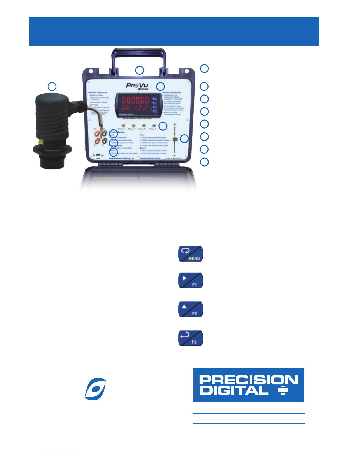
External 4-20 mA Transmitter
(Not Included)
Easy-to-Carry Case
Fully Functional
ProVu Meter
4-20 mA Analog Input
Transmitter Power
Onboard USB Connection
Relay Status Indicators
0-10 V Analog Input Simulator
233 South Street
Hopkinton MA 01748-2208 USA
Tel. (508) 655-7300 www.predig.com
P
R
V
U
S
ERIES
®
1 3
2
7
6
4
5
4
5
6
7
8
1
2
3
8
ProVu PDD6000 Demonstrator
Instruction Manual
Page 2
2
The
ProVu Demonstrator will serve to demonstrate both the PD6000 and the PD6200. The
actual product installed in the demonstrator is a PD6200 with the factory default settings
changed to make it function as a PD6000. However, when total is turned on in the system
menu, the unit will function as a PD6200. To prepare the meter for demonstration, reset the
meter to it’s factory default settings by following the instructions below.
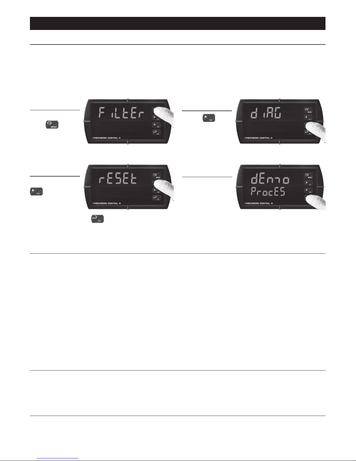
Preparing the Meter for Demonstration
Press and
hold for
ve seconds
to enter the
Advanced Features Menu.
Press
until
the diAG (diagnostics) menu
is displayed.
Press and hold
until the
meter ashes
rESEt (reset).
Immediately press to reset the meter to
factory defaults.
The meter will
ash all of the
LED segments
and then display dEnmo ProcES (Demo Process). The
meter has been reset to its defaults.
About the Factory Default Settings
The factory defaults congure the meter to have an input display range of 0 to 8000 with
a corresponding 0 to 10 V input from the slider. The secondary display is programmed to
display GAL (gallons). The Total and Dual Scale features are turned off.
Relays 1 and 2 are congured as alarms. Relay 1 is a low alarm with a set point of 495 and
reset point of 750. Relay 2 is a high alarm with a set point of 7500 and reset point of 6900.
Relays 3 and 4 are congured for pump alternation control. The relays alternate being on
at a set point of 6000 and reset point of 1000. Both relays will turn on at a set point of 7000,
and both off at 1000.
The alarm indicators on the meter; and the relay indicators on the demonstrator will indicate
the relay states.
Voltage Simulator (PV)
The slide control on the right side of the demonstrator serves as the 0-10 V signal simulator. The input signal increases as the slider is moved upward, and decreases when slider is
moved downward.
Micro USB Connection
The PDD6000 Demonstrator includes a micro USB connector to demonstrate programming
from a PC. MeterView Pro software is included onboard and will install automatically when
the unit is plugged into a computer.
1
2
3
4
ProVu PDD6000 Demonstrator
Instruction Manual
Page 3
3
Demonstrating the PD6000 Process Meter
The ProVu Demo comes programmed with factory defaults that make it ready to demonstrate the features of the PD6000 immediately, with no additional programming required.
The following steps describe how to demonstrate the relay alarm and pump alternation
features of the meter using the factory default settings.
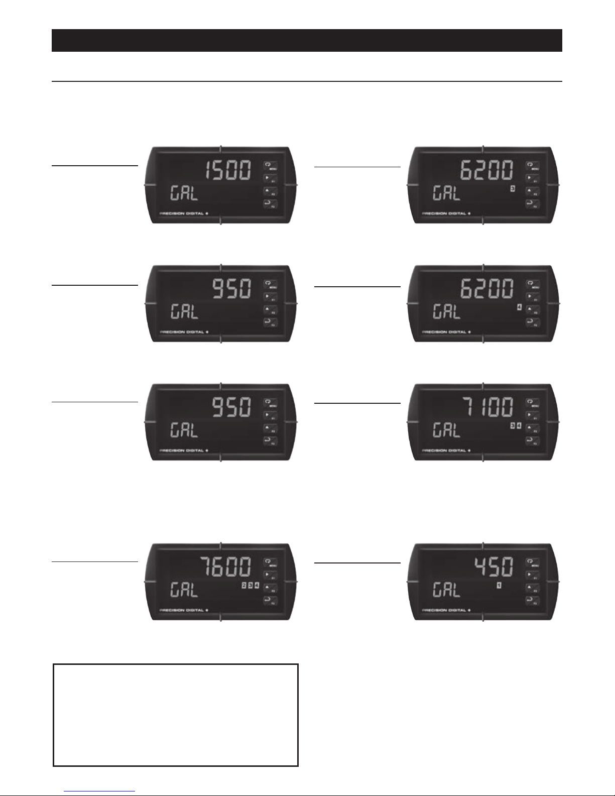
Use the 0 to
10 V simulator
to adjust the
display reading
so the meter reads around 1500 gallons.
All relay lights should be off.
Raise the slide
wire until the
meter reads
around 6200
gallons. Relay number three will come on.
Notice the relay light in the above graphic.
Lower the slide
wire until the
meter reads
around 950 gallons. Relay number three should turn off.
Raise the slide
wire until the
meter reads
around 6200
gallons. Relay number four will come on. This
demonstrates the pump alternation feature.
Lower the slide
wire until the
meter reads
around 950
gallons. Relay number four should turn off.
Do this a couple times so the customer can
see the pump alternation workings, and get
their head around the concept. Discuss the
advantages of this feature.
Now, raise
the slide wire
until the meter
reads around
7100 gallons. Relays number three and four
should be on, indicating both pumps on.
Keep raising
the slide wire
until the meter
reads around
7600 gallons. Relay number two will come
on, indicating the high level alarm.
Now lower the
slide wire. At
around 900
gallons, relays
number four, three, and two will turn off
indicating the high alarm has cleared and
the two pumps have been shut off. Keep
lowering the slide wire until the meter reads
around 450 gallons. Relay number one will
come on, indicating the low level alarm.
Note: The
ProVu can be congured to
control up to 8 pumps. Please
refer to the section in the PD6000
Instruction Manual entitled Pump Al-
ternation Control Applications found
under Relay Operation Details.
1
2
3
4
5
6
7
8
ProVu PDD6000 Demonstrator
Instruction Manual
Page 4
4
Program Other Process Alarm Types
The ProVu can be congured to control up to 8 pumps. In order to show the versatility
of the relay operations available on the ProVu, this next sequence will change the relay
action of alarm #2 to latching. This means that the alarm state will remain in effect until the
Acknowledge Button is pressed.
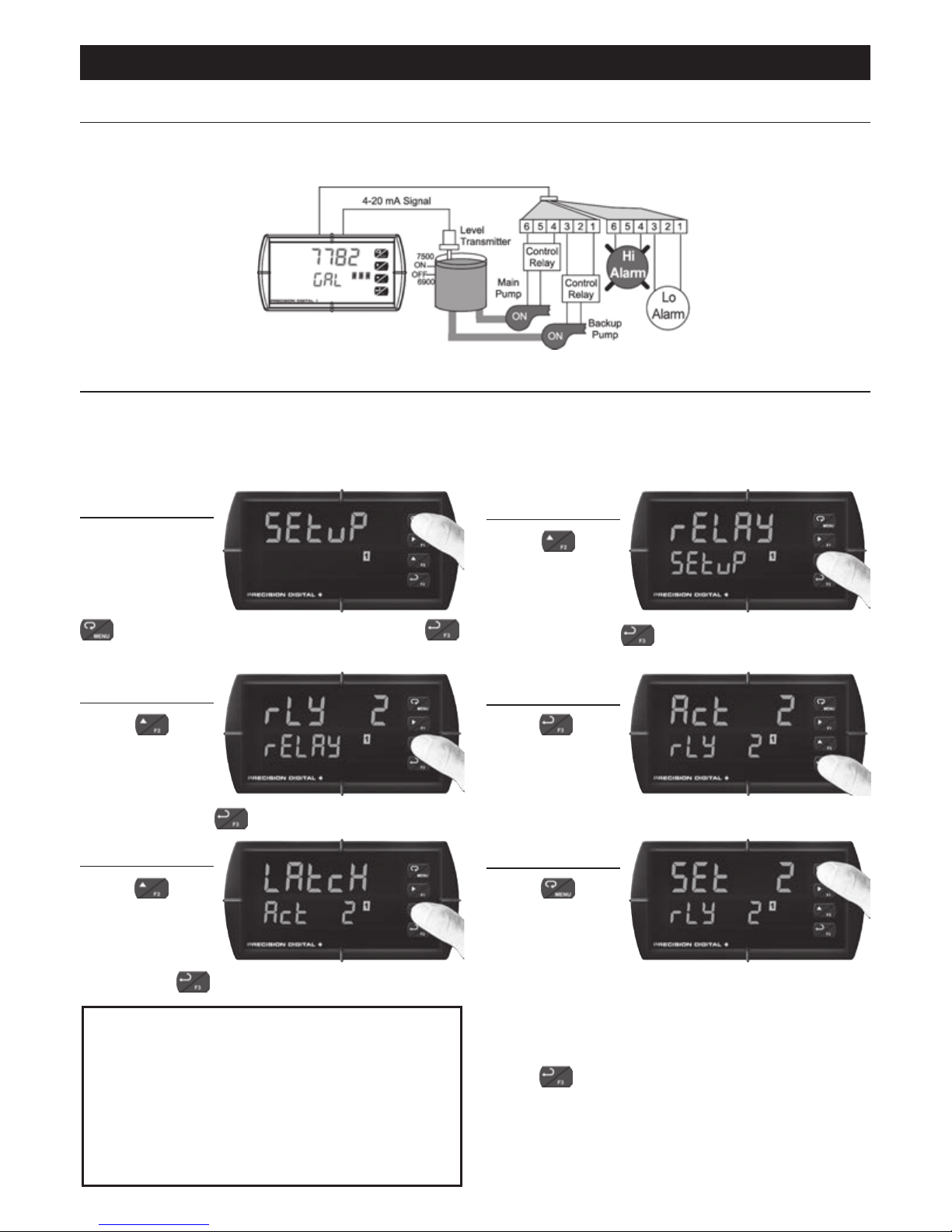
Move the Voltage Simulator
to its lowest
position. Press
to enter Programming Mode, press
to access the SEtup (Setup) menu.
Press
until the rELay
(Relay) menu
is displayed
and then press .
Press
until
the rLy 2
(Relay 2) menu
is displayed
and then press .
Press to
access the
Act 2 (Relay
2 Action) menu.
Press
until
LAtcH (Latch-
ing Action) is
displayed and
then press .
Press to
return to Run
Mode. Increase
the input signal
using the Voltage Simulator to a value
above the relay 2 alarm set point of 7500,
and then reduce it to below 1000. The relay
will remain on, or latched. However, if you
press
, it will unlatch the relay. Experiment with other relay functions following
the instructions in the PD6000 instruction
manual under the section entitled "Setting
the Relay Operation".
Note: The F3 button is programmed to function
as an Acknowledge Button by default. Input 4 on the front panel of the demonstrator is programmed to function as F3 by
default, so the digital input push-button
labeled 'Input 4' may also be used to
acknowledge the alarm.
More about Pump Alternation Control
The following diagram shows the previously described pump alternation control setup.
Please refer to the section in the Instruction Manual entitled "Pump Alternation Control Applications."
1
2
3
4
6
5
ProVu PDD6000 Demonstrator
Instruction Manual
Page 5
5
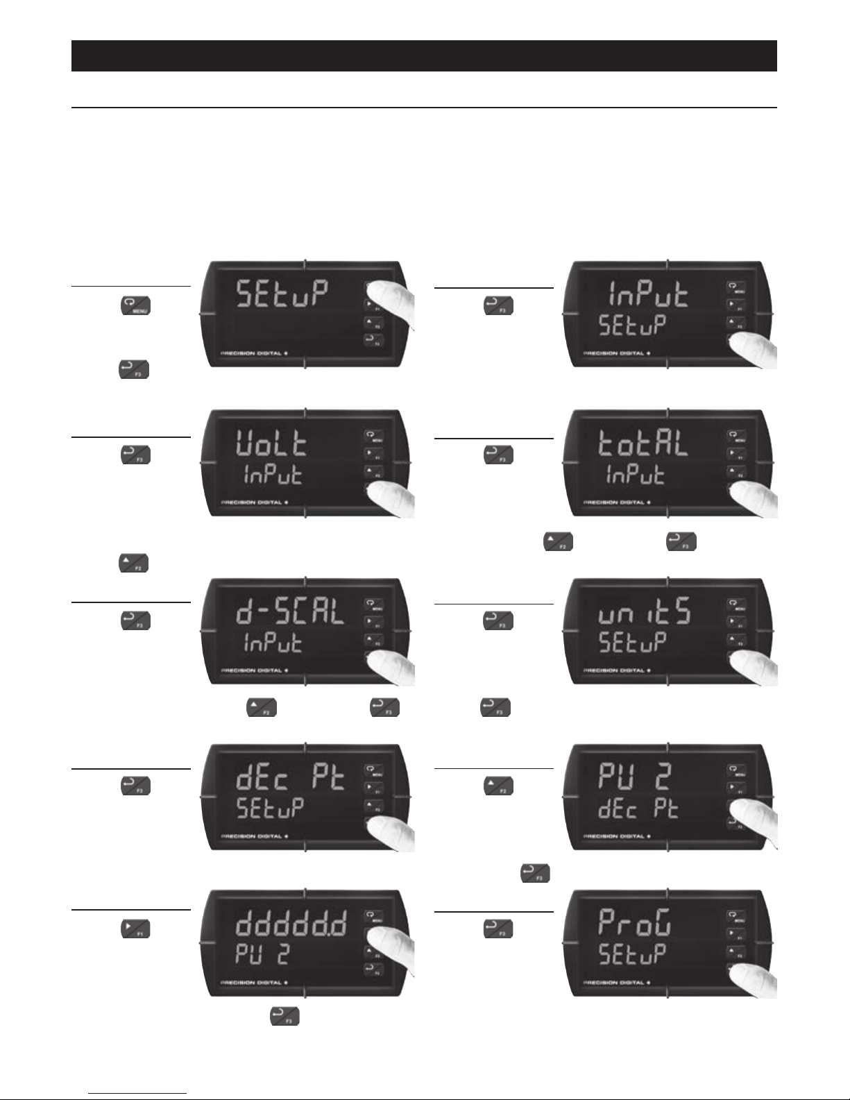
Dual-Scale Level Display
The ProVu dual-scale level display allows the single process input to be scaled independently into two different display values. This is most commonly used in level applications to
display height and volume, height and percent, volume and percent, or other combinations
of variables that can be derived from the single process input. Both process variables may
be displayed simultaneously on the dual-line display.
The following setup will congure the second line of the display to scale the process variable input to be 0.0 to 25.5 feet.
Press
to
enter Program-
ming Mode,
press
to
access the SEtup (Setup) menu.
Press
to
access the
Input (Input)
menu.
Press to
accept the
volt (Volt-
age) input.
This should be the default option. If it is not,
press to select it.
Press
to
access the
total (Total)
menu, select
no (No) using
, then press to accept.
Press
to
access the
d-SCAL (Dual
Scale) menu,
select yes (Yes) using
, then press
to accept. This enables dual scaling.
Press
to
access the
units (Units)
menu then
press
to accept the default unit tag (GAL).
Press
to
access the
dec pt
(Decimal Point)
menu.
Press until
pv 2 (Process
Variable 2) is
displayed and
then press to access.
Press
until
ddddd . d (First
Decimal Point
Location) is
displayed and then press to accept.
Press to
access the
ProG (Program)
menu.
1
2
3
4
6
5
7
8
10
9
ProVu PDD6000 Demonstrator
Instruction Manual
Page 6
6
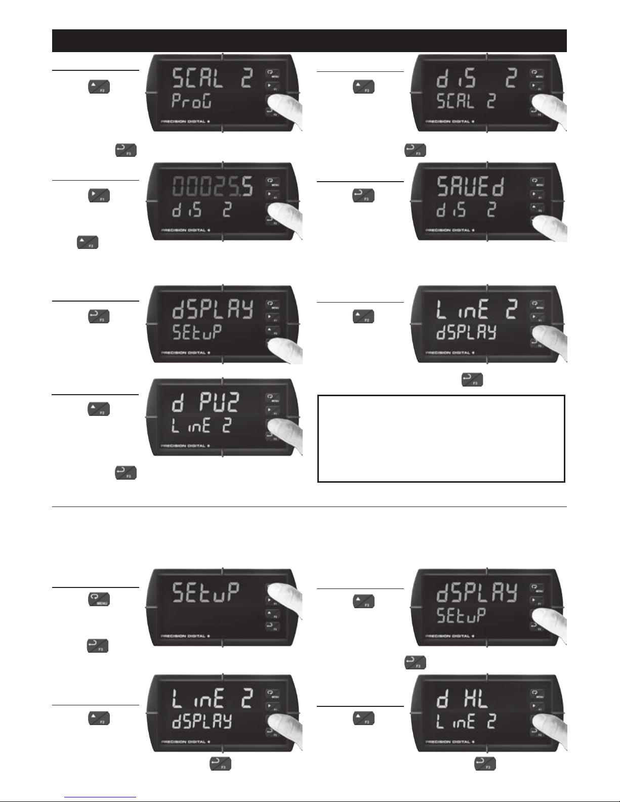
Press
until SCAL 2
(Scale PV2) is
displayed and
then press to accept.
Press until
diS 2 (High
Display Value)
is displayed
and then press to accept.
Using
to
change which
digit is selected
and
to in-
crement the selected digit, change the high
display value to 00025 . 5 (25.5).
Press
to
accept the new
value. The meter will display
SAvEd (Saved).
Press
to
access the
dsplay (Dis-
play) menu.
Press
until
the line 2
(Display Line
2) menu is
displayed and then press to access.
Press
until
d pv2 (Dis-
play PV2) is
displayed and
then press to accept.
Note: PV2 will now be displayed on display
line 2, where the units tag (GAL) was
displayed previously. Move the 0-10 V
simulator up and down to demonstrate
this capability.
Max/Min (Peak/Valley) Display
The ProVu has the capability of tracking and storing the maximum and minimum display
values since last reset. The meter can be programmed to display maximum only, minimum
only, or alternate between maximum and minimum. The following setup will congure the
meter to alternate between maximum and minimum.
Press
to
enter Program-
ming Mode,
press
to
access the SEtup (Setup) menu.
Press
until
the dsplay
(Display) menu
is displayed
and then press .
Press
until
the line 2
(Display Line 2)
is displayed and then press .
Press until
the d HL (Display High/Low)
is displayed and then press .
11 (dual-scale cont.)
12
13
14
16
15
17
1
2
3
4
ProVu PDD6000 Demonstrator
Instruction Manual
Page 7
7
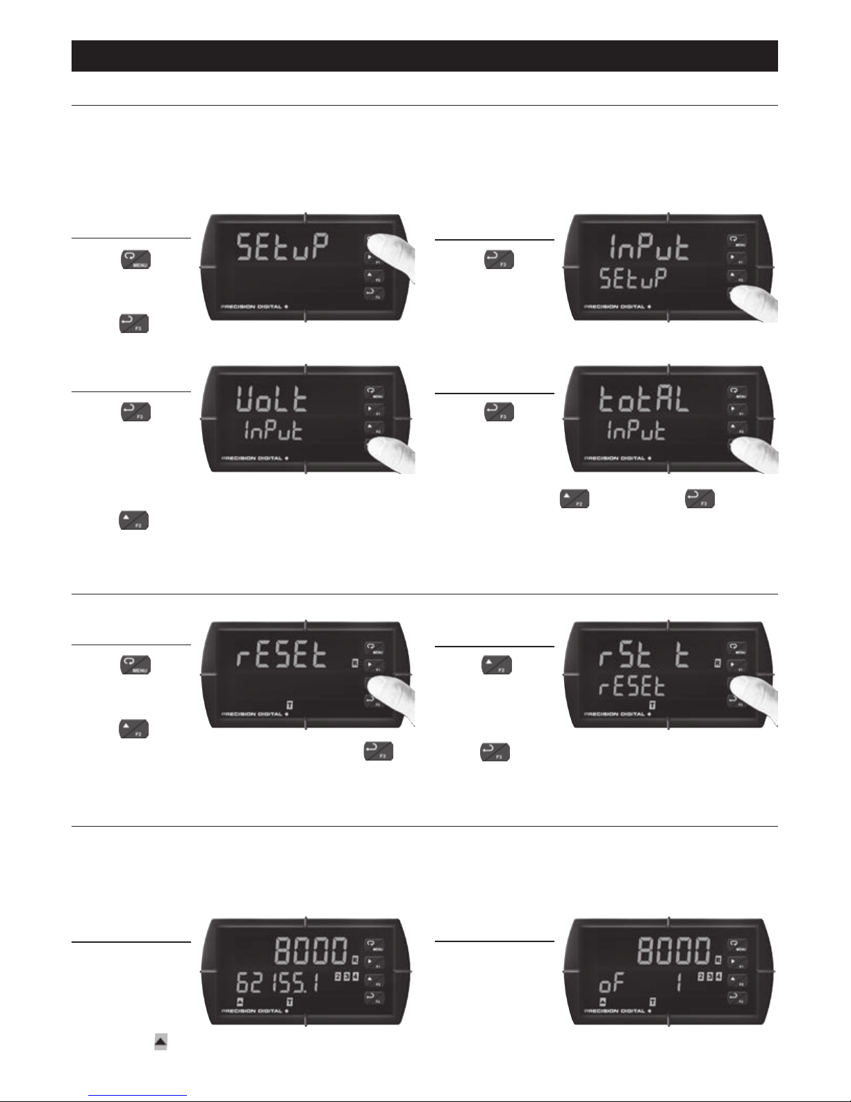
Demonstrating the PD6200 Rate/Totalizer
The totalizer needs to be turned on in order to demonstrate the process meter (PD6200).
Typically, Rate will be displayed in display line 1 (as denoted by the Rate indicator – R to
the right), and Total will be displayed in display line 2 (as denoted by the Total indicator – T
underneath). The following setup will congure the meter to function as a PD6200 Rate/
Totalizer.
Press
to
enter Program-
ming Mode,
press
to
access the SEtup (Setup) menu.
Press
to
access the
Input (Input)
menu.
Press to
accept the
volt (Volt-
age) input.
This should be the default option. If it is not,
press to select it.
Press to
access the
total (Total)
menu, select
yes (Yes) using
, then press to
accept. The meter will now function as a
PD6200 Rate/Totalizer
Press
to
enter Program-
ming Mode,
press
until
rESEt (Reset) is displayed and press
to
access this menu.
Press
until
rSt t (Reset
Total) is displayed and then
press . This will reset the total count which
is displayed on display line 2.
When the total
reaches greater
than six digits,
the overow
indicator (
) will illuminate.
The display
will alternate to
show the cut off
leading digits of
the number.
Reset the Total
Resetting the meter does not reset the Total value to zero, this must be done manually.
Overow Display
The ProVu can display up to 9 digits for Total or Grand Total. To demonstrate this capability,
move the 0-10 V simulator all the way to the top. When the total reaches greater than six
digits, display line 2 will alternate between the overow digits and the rst six digits of the
number. The display will alternate as illustrated below.
1
2
3
4
2
1
1
2
ProVu PDD6000 Demonstrator
Instruction Manual
Page 8
8
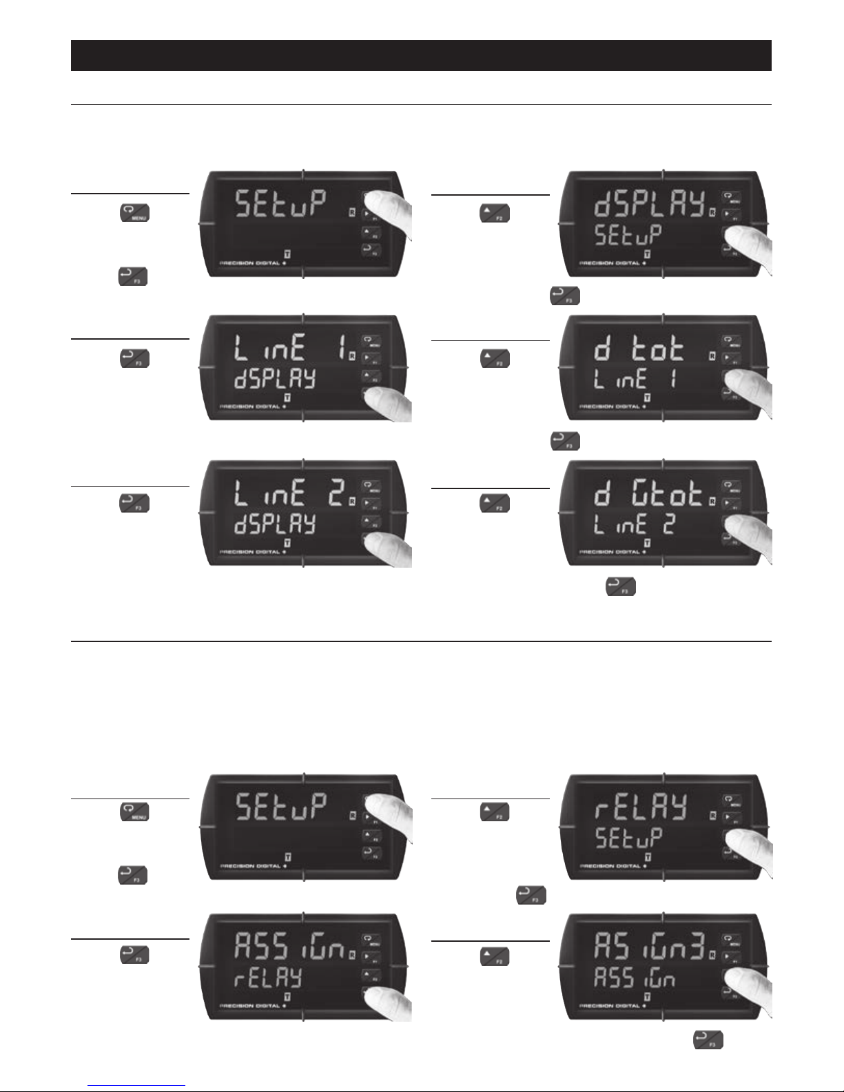
Press
to
enter Program-
ming Mode,
press
to
access the SEtup (Setup) menu.
Press
until
the dsplay
(Display) menu
is displayed
and then press .
Display Total and Grand Total
The ProVu may show the Total and Grand Total simultaneously using the dual-line display.
The following instructions will congure display line 1 to read Total and display line 2 to read
Grand Total.
Press
to access
the LinE 1
(Display Line
1) menu.
Press
until the d tot
(Display Total)
is displayed
and then press
.
Press
to access
the line 2
(Display Line
2) menu.
Press until
the d gtot
(Display Grand
Total) is displayed and then press
.
Press
to
enter Program-
ming Mode,
press
to
access the SEtup (Setup) menu.
Press
until the relay
(Relay) menu is
displayed and
then press .
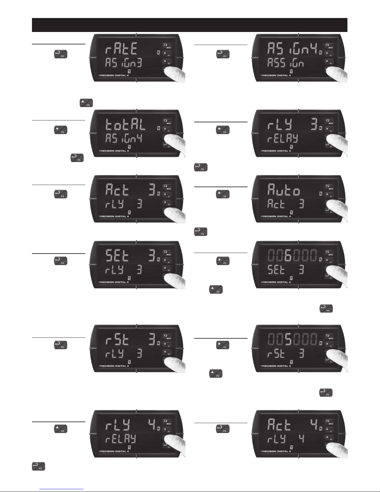
Program Rate & Total Alarms
The relays on the ProVu can be programmed to be based on the rate or total. The following
instructions will congure relay 3 as a high rate alarm with set point of 6000 and a reset
point of 5000, and relay 4 as a total alarm with a set point of 30000.
Note: Factory default sets relays 1 and 2 to be used for high and low alarms. The default meter congu-
ration of the demonstrator is for level or process displays, however these alarms will function as
rate alarms when the totalizer functions of the PD6200 are enabled.
Press to
access the
Assign (Relay
Assignment)
menu.
Press
until
the asign3
(Relay #3
Assignment)
menu is displayed and then press .
2
1
4
3
6
5
2
1
43
ProVu PDD6000 Demonstrator
Instruction Manual
Page 9
9
Press
to
accept rate
(Rate) as the
relay assignment. This should be the default option, but
if it is not use to select it.
Press
to
access the
Asign4 (Relay
#4 Assignment)
menu.
Press
until
total (Total) is
displayed and
then press .
Press until
rly 3 (Relay
#3) is displayed
and then press
to access this menu.
Press
to
access the
Act 3 (Relay
#3 Action)
menu.
Press until
auto (Automat-
ic) is displayed
and then press
to accept automatic operation.
Press to
access the
set 3 (Relay
#3 Set Point)
menu.
Using to
change which
digit is selected
and
to
increment the selected digit, change the set
point value to 006000 (6000). Press to
accept this new value..
Press
to
access the
rst 3 (Relay
#3 Reset Point)
menu.
Using to
change which
digit is selected
and
to
increment the selected digit, change the set
point value to 005000 (5000). Press to
accept this new value.
Press
until
rly 4 (Relay
#4) is displayed
and then press
to access this menu.
Press to
access the
Act 4 (Relay
#4 Action)
menu.
5 (alarms cont.)
6
7
8
10
9
11
12
13
14
16
15
ProVu PDD6000 Demonstrator
Instruction Manual
Page 10
10
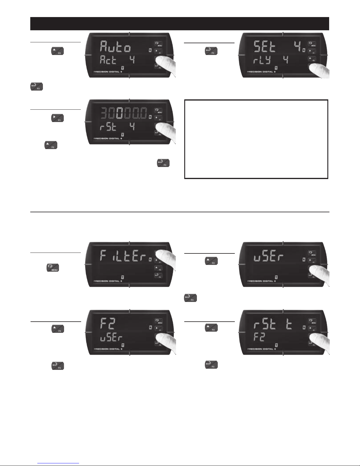
Press
until
auto (Automat-
ic) is displayed
and then press
to accept automatic operation.
Press
to
access the
set 4 (Relay
#4 Set Point)
menu.
Using
to
change which
digit is selected
and
to
increment the selected digit, change the set
point value to 30000 . 0 (30,000). Press
to accept this new value.
Note: Alarm #3 will set if the rate increases
above 6,000 and will reset when the
rate drops below 5,000. Use the 0-10 V
simulator to demonstrate this. Alarm #4
will set when the total reaches 30,000
and will reset once the total is reset to
zero. While the total is easily reset via the
menu system, it can also be reset via a
function key, or external digital input as
shown below.
Function Key & Digital I/O Programming
The meter buttons (F1-F3) can be programmed to perform different actions than they do by
default. The following steps show how to program the F2 function key to reset the total.
Press and
hold
for
ve seconds
to enter the
Advanced Features Menu.
Press
until
the uSEr (User)
menu is displayed. Press
to access this menu.
Press
until the F2 (F2
Button) menu
is displayed.
Press to access this menu.
Press
until rst t
(Reset Total)
is displayed.
Press to accept. The F2 button is now
programmed to reset the total to zero. Try
returning to run mode and resetting the total
with the F2 button.
17 (alarms cont.)
18
19
1
2
3
4
ProVu PDD6000 Demonstrator
Instruction Manual
Page 11
11
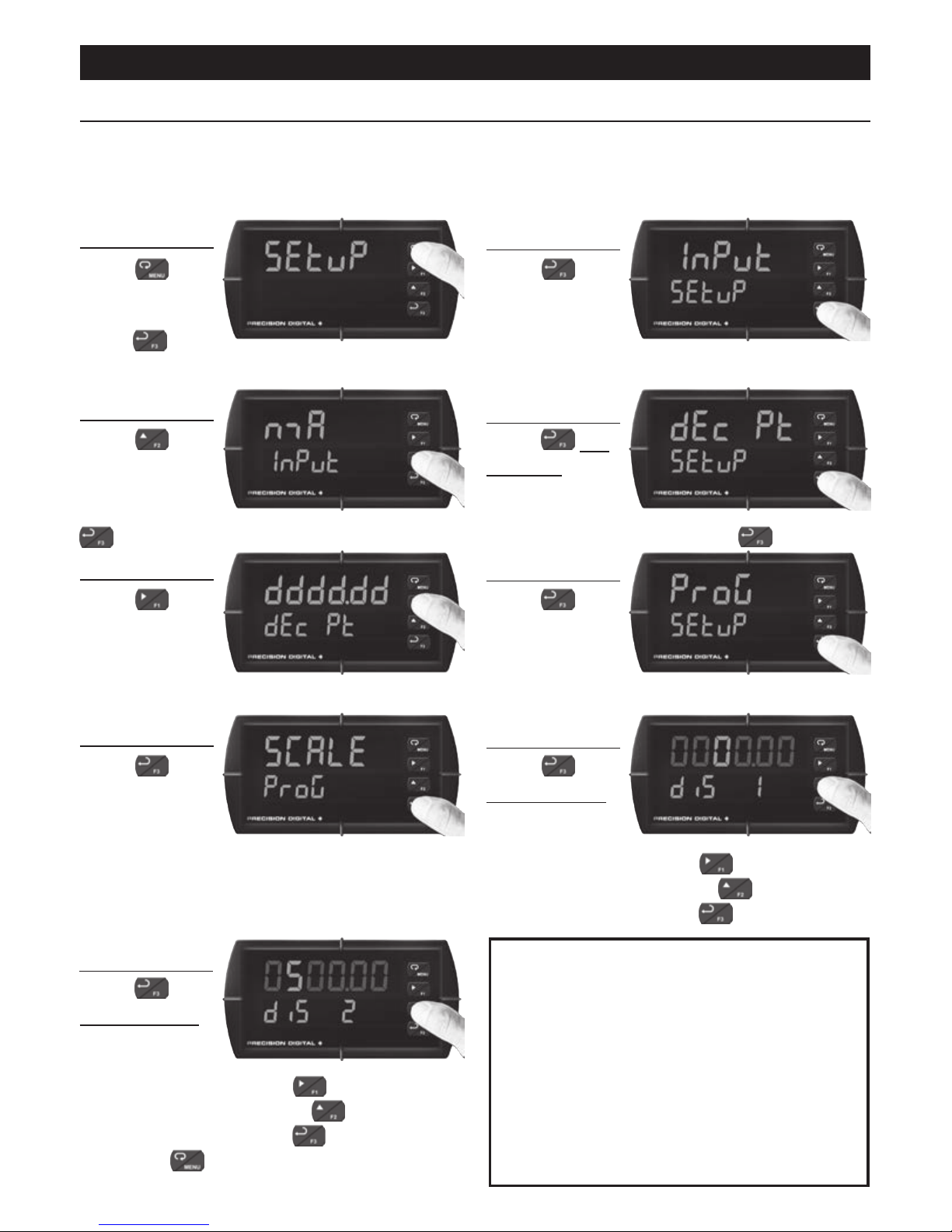
Connecting a Transmitter to the Demonstrator
The ProVu demonstrator has been designed to power an external transmitter with up to
200 mA of 24 V excitation. The demonstrator has signal input terminals to accept a 4-20
mA signal. Demonstrate one of your transmitters along with the ProVu! The following steps
show how to select the scaling of the meter to match your transmitter.
Press
to
enter Program-
ming Mode,
press
to
access the SEtup (Setup) menu.
Press
to
access the
Input (Input)
menu.
Press
until
nma (milliamp)
is displayed
and then press
to accept as the input type.
Press six
(6) times, until
the dec pt
(Decimal Point)
menu is displayed and press to access.
Press
until
the desired
decimal point
location is
displayed.
Press to
access the
ProG (Program)
menu.
Press
to
access the
SCALE (Scale)
menu.
Press
multiple times,
until dis 1
(Low Display
Value) is displayed. Use
to change
which digit is selected and
to increment
the selected digit. Press
when done.
Press
multiple times,
until dis 2
(High Display
Value) is displayed. Use
to change
which digit is selected and
to increment
the selected digit. Press
when done
and press
to return to Run Mode.
Note: To connect your transmitter to the ProVu
demo, use the wiring diagrams provided
on the back page of this manual. Connect
the transmitter to the 24V supply using
the P+ and P- terminals. Connect the 4-20
mA input signal from the transmitter to the
mA+ and COM input terminals.
Be sure to observe polarity!
The current input is protected against
current overload by a resettable fuse.
However, the display may or may not
show a fault condition.
1
2
3
4
6
5
7
8
9
ProVu PDD6000 Demonstrator
Instruction Manual
Page 12
Instruction Manual
12
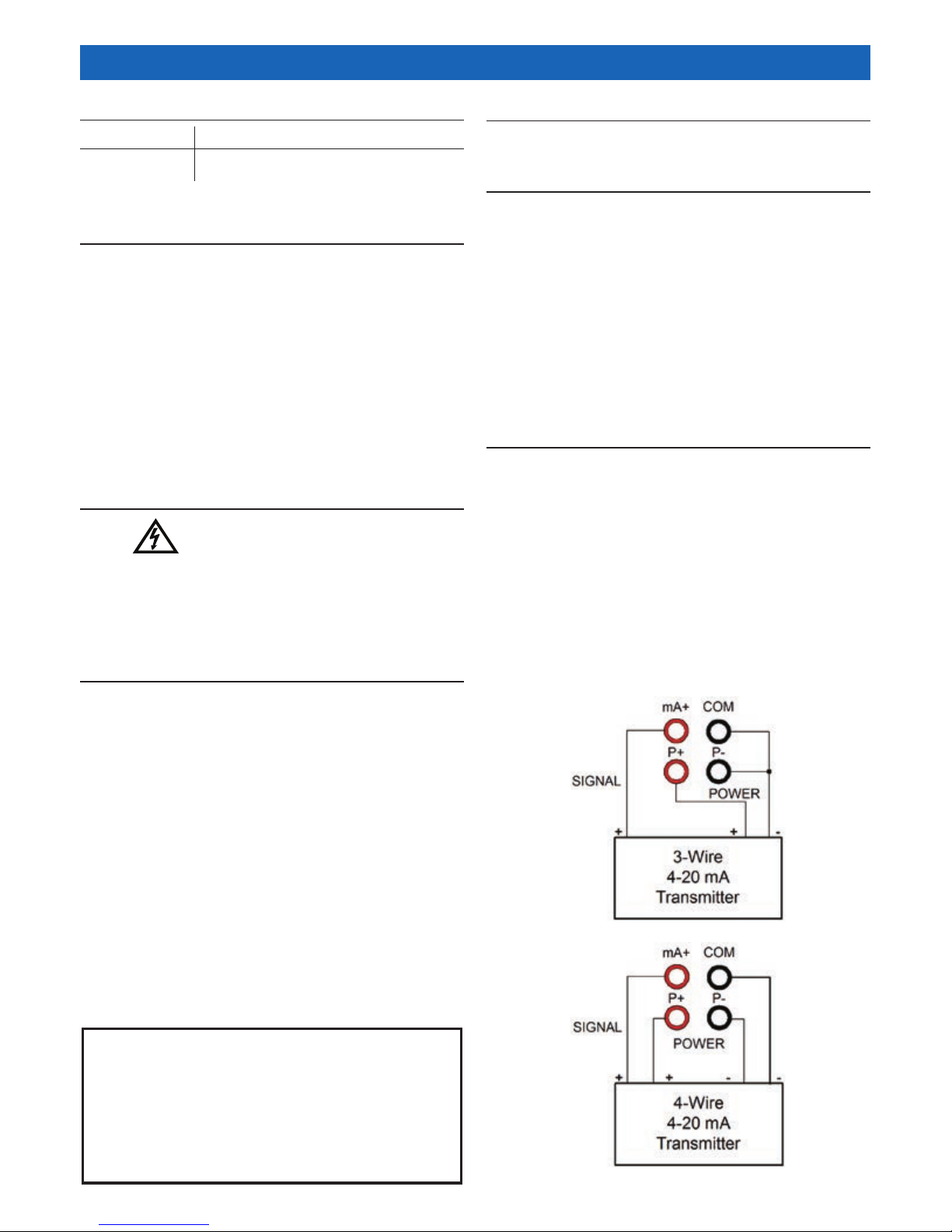
4-20 Transmitter Connections
Wiring for a 3 wire external 4-20 mA transmitter.
Wiring for a 4 wire external 4-20 mA transmitter.
The wiring diagrams below show how to
connect an external 4-20 mA transmitter to
the ProVu Demonstrator.
The ProVu meter must be set up to accept a 4-20 mA input when connecting a
transmitter or a 4-20 mA signal source to the
input terminals on the side of the demo.
The transmitter may be powered by the
internal 24 VDC power supply available at
terminals labeled P+ and P-.
Ordering Information
Model
PDD6000
Note: The ProVu meter in the ProVu Demo is not intended for resale.
Parts Included
1. PD6200 assembled in convenient hand
carry enclosure
2. Power Cord
3. Micro USB Cable
4. Product Documentation and USB Driver CD
5.
ProVu Demonstrator Instruction Manual
(This Document)
Description
ProVu Demo Unit
Warranty
2 years parts and labor
Safety Information
WARNING
Hazardous voltages exist within enclosure.
Service should be performed only by trained
service personnel.
Power Connection
The ProVu Demonstrator has a power cord
that plugs into a USA standard 115 VAC
power outlet.
To power the Demonstrator from other
power sources such as 230 VAC, the user
must provide the necessary plug adapter.
Refer to the PD6000/PD6200 instruction
manual for power specications.
While there are some instructions in
this manual related to the demonstration of the ProVu, please refer
to the PD6000 or PD6200 Instruction Manual for more complete details on how to program the meter.
Important Notes
The PD6200 included with the demonstrator
is congured by default to demonstrate the
PD6000 with the dual-scale level feature
turned off. To demonstrate this feature,
d-SCAL must be set to ON in the menu
system.
There are strong benets of demonstrating both the PD6200 & PD6000 exactly as
shown in this manual in order to show all the
important features of the ProVu.
Make sure to have the ProVu data sheet
open and available to the customer when
demonstrating!
ProVu PDD6000 Demonstrator
LIMD6000_E - 01/16
 Loading...