

Page 1
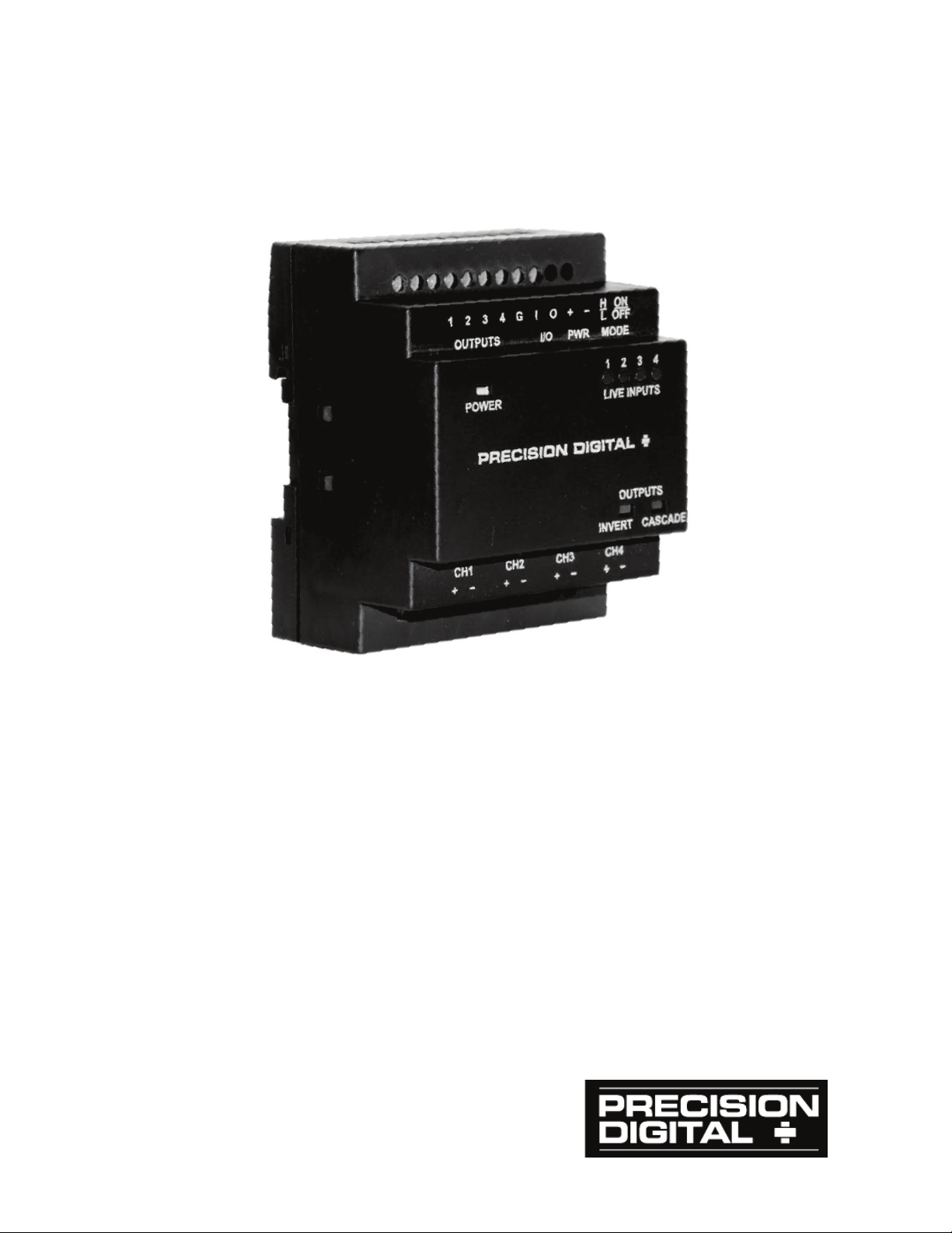
PDA1500 High Voltage AC/DC
to Logic Le vel Con verter
Instruction Manual
x Combine with the Vigilant e® II Annunciator
to Monitor High Voltages
x Four High Voltage Inputs Up to 265 VAC or VDC
x Four Digital 5 VDC Outputs
x Easy DIN Rail Mounting
x Simple Two-Button Setup
x Cascade Mode for Series Break Configurations
x Multi-Unit Cascade Mode
PRECISION DIGITAL CORPORATION
Find Quality Products Online at: [email protected]
www.GlobalTestSupply.com
Page 2
Model PDA1500 Logic Level Converter Instruction Manual
CAUTION
Read complete instructions
operation of the meter.
WARNING
Warning
This product is not recommended for life support applic ations
or applications
injury or property loss. Anyone using this product for such
applications does so at his/her own risk. Precision Digital
Corporation shall not be held liable for damages resulting from
such improper use.
!
Disclaimer
The information contained in this document is subject to change
without notice. Precision Digital makes no representations or
warranties with respect to the contents hereof and specifically
disclaims any implied warranties of merchantability or fitness for a
particular purpose.
Risk of electric shock or
prior to installation and
personal injury.
where malfunctioning could result in personal
Limited Warranty
Precision Digital Corporation warrants this product against defects in
material or workmanship for the specified period under
“Specifications” from the date of shipment from the factory. Precision
Digital’s liability under this limited warranty shall not exceed the
purchase value, repair, or replacement of the defective unit.
Registered Trademarks
PROVU® and Vigilante® are a registered trademarks of Precision Digital
Corporation. All other trademarks mentioned in this document are the
property of their respective owners.
Find Quality Products Online at: [email protected]
© 2014 Precision Digital Corporation. All rights reserved.
2
www.GlobalTestSupply.com
Page 3

Model PDA1500 Logic Level Converter Instruction Manual
Table of Contents
INTRODUCTION ------------------------------------------------------------ 5
ORDERING INFORMATION --------------------------------------------- 5
SPECIFICATIONS ---------------------------------------------------------- 6
General ------------------------------------------------------------------------------- 6
SAFETY INFORMATION ------------------------------------------------- 8
INSTALLATION ------------------------------------------------------------- 8
Unpacking --------------------------------------------------------------------------- 8
DIN Rail Mounting Instructions ---------------------------------------------- 9
DIN Rail Mounting Requirements ------------------------------------------ 9
Snap-On Mounting M ethod -------------------------------------------------- 9
Removing the Converter from the DIN Rail ---------------------------- 10
CONNECTIONS & SETUP ---------------------------------------------- 1 1
Wiring & Connections --------------------------------------------------------- 11
Connector Markings --------------------------------------------------------- 12
Power Connections ---------------------------------------------------------- 13
Input Signal Connections --------------------------------------------------- 13
Digital Output Connections ------------------------------------------------- 14
Cascade Mode Multiple Unit I/O Connections ------------------------ 14
Mode Selection Latching Pushbuttons --------------------------------- 15
Normal/Cascade Mode ON/OFF Button -------------------------------- 15
Output H/L Inverter Mode -------------------------------------------------- 16
LED INDICATORS--------------------------------------------------------- 17
OPERATION ---------------------------------------------------------------- 18
Normal Mode --------------------------------------------------------------------- 18
Inverted Mode -------------------------------------------------------------------- 18
Cascade Mode ------------------------------------------------------------------- 19
Inverted Cascade Mode ------------------------------------------------------ 20
Multiple Unit Cascade Mode ------------------------------------------------ 21
MOUNTING DIMENSIONS ---------------------------------------------- 22
TROUBLESHOOTING ---------------------------------------------------- 23
3
Find Quality Products Online at: [email protected]
www.GlobalTestSupply.com
Page 4

Model PDA1500 Logic Level Converter Instruction Manual
Table of Figures
Figure 1. Conne
Figure 2. Power Connections ............................................................ 13
Figure 3. High Voltage Input Channel Connections ........................ 13
Figure 4. Digital Output Connections ............................................... 14
Figure 5. Cascade Mode Multiple Unit I/O Connections.................. 14
Figure 6. Normal Mode ON/OFF (Cascade Mode) Switch ............... 15
Figure 7. Inverted H/L Switch Set to Low ......................................... 16
Figure 8. Dimensions - Front View .................................................... 22
Figure 9. Dimensions - Side View ..................................................... 22
Table 1. Normal and Inverse Operation Logic ................................. 18
Table 2. Cascade Mode Operation Logic Example 1 ....................... 19
Table 3. Cascade Mode Operation Logic Example 2 ....................... 19
Table 4. Inverted Cascade Mode Operation Logic Example 1 ........ 20
Table 5. Inverted Cascade Mode Operation Logic Example 2 ........ 20
Table 6. Multiple Unit Cascade Mode Operation Logic ................... 21
ctor Markings ........................................................... 12
4
Find Quality Products Online at: [email protected]
www.GlobalTestSupply.com
Page 5
Model PDA1500 Logic Level Converter Instruction Manual
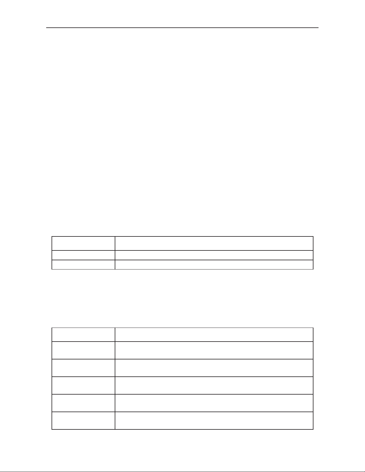
Model
Description
PDA1500-115
85-130 VAC or VDC to Logic Level Converter
PDA1500-230
185-265 VAC or VDC to Logic Le vel C onverter
Model
Description
PD154
Vigilante II 4-Point Alarm Annunciator
Powered from 85-265 VAC
PD154
Vigilante II 4-Point Alarm Annunciator
Powered from 12-36 VDC
PD158
Vigilante II 8-Point Alarm Annunciator
Powered from 85-265 VAC
PD158
Vigilante II 8-Point Alarm Annunciator
Powered from 12-36 VDC
PDA1044
ProVu 4 Digital Inputs and 4 Digital Outputs
M-Link Expansion Module
INTRODUCTION
The PDA1500 High VAC/VDC to Logic Level Converter is an easy to
use DIN rail mounted device for converting high voltage signals into
logic level signals for use as a digital inpu t to a wide range of proce ss
control and display equipment.
The PDA1500 accepts up to four high voltage AC or DC signals. The
PDA1500-115 inputs accept 85-130 VAC or VDC, and the PDA1500230 inputs accept 185-265 VAC or VDC. Powered from 12-24 VDC, the
PDA1500 can drive outputs even when no high voltage inputs are
present. The outputs are user selectable for high or low states when
voltage is present at the inputs.
Cascade mode is ideal for monitoring signals that can result in
cascading or subsequent failures. This mode monitors the point of
failure, when a failure in a single input causes a failure in all alarm
points in a “series” sy st em.
The PDA1500 is mounted in an ABS plastic DIN rail mounted enclosure
for easy mounting inside a panel or instrument enclosure.
ORDERING INFORMATION
Recommended Associated Products
The PDA1500 High Voltage to Logic Level Converter is ideal for
providing alarm and status indication to the following Precision Digital
monitoring and control products.
-6R2-1
-7R2-0
-6R2-1
-7R2-0
5
Find Quality Products Online at: [email protected]
www.GlobalTestSupply.com
Page 6
Model PDA1500 Logic Level Converter Instruction Manual
CONFIGURATION
METHOD
Two latching pushbuttons for selection of output state inversion
and cascade mode selection. No other programming required.
INDICATORS
One green power LED. Four red LED indicators to monitor live
inputs on channels 1
yellow LED indicators for inverted
output and/or cascade output mode.
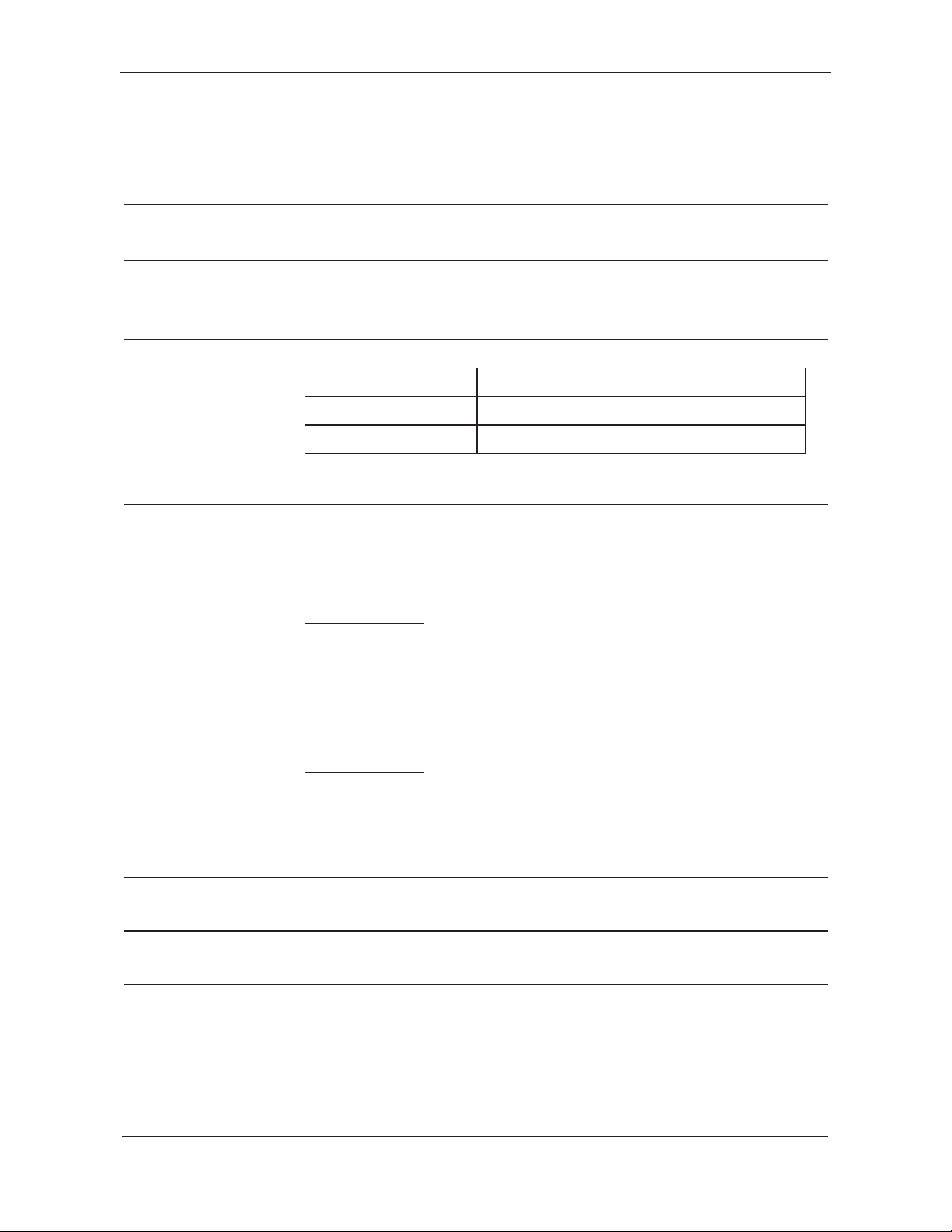
INPUT
CHANNELS
Four independent, isolated input channels CH1 to CH4
Model
Input Voltage
PDA1500-115
85-130 VAC or VDC
PDA1500-230
185-265 VAC or VDC
Inputs feature high common mode
, ideal for noisy
environments.
INPUT VOLTAGE
THRESHOLD
Input high voltage levels are different for AC and DC
voltages.
ermine threshold
for AC inpu t
PDA1500
Input High
60 VAC RMS (85 VAC peak)
Input Low Threshold Range
31 VAC RM S ( 4 4 VAC
PDA1500
Input High Threshold Range
131 VAC RMS (185 VAC
Input Low Threshold
66 VAC RMS (94 VAC peak) or 94 VDC, ±5%
INPUT
CURRENT
1.2 mA (typical) at “turn-o n” or high input voltage
PROPAGATION
DELAYS
Input Propagation Delay to Logic Low: 4μs (typ); 15μs (max)
Input Propagation Delay to Logic High: 8μs (typ); 40μs (max)
INPUT
IMPEDANCE
PDA1500-115: >60kΩ total impedance per channel
PDA1500-230: >140kΩ total impedance per channel
INPUT
OVERLOAD
Must not exceed 50 mA DC (35 mA RMS) on input channels.
Maximum input power dissipation is 230 mW.
Surge protection included for up to 140
protection included for up to 500 mA.
SPECIFICATIONS
Except where noted all specifications apply to operation at +25°C.
General
-4. Two
rejection
Find Quality Products Online at: [email protected]
www.GlobalTestSupply.com
Instantaneous value is used to det
- RMS equivalents are shown below.
-115
Threshold Range:
or 85 VDC, ±5%
:
peak) or 44 VDC, ±5%
-230
:
peak) or 185 VDC, ±5%
Range:
mA. Transien t
6
Page 7

Model PDA1500 Logic Level Converter Instruction Manual
DIGITAL
OUTPUTS
Four TTL Logic (5V) independent digital outputs.
OUTPUT LOGIC
LEVELS
Output Low: 0 to 0.33 V
Output High: 4.4 to 5.0 V
CASCADE MODE
Typically used in Boiler applications to monitor for and detect
fault conditions. See page
POWER
12
circuit
protected. Isolated.
MAX POWER
DISSAPATION
PDA1500-115: 3W (total dissipation of unit)
PDA1500-230: 4W (total dissipation of unit)
ISOLATION
630 VRMS between input channels; 3750 VRMS input-topower line;
output-to-
power line
OVERVOLTAGE
Maximum overvoltage (transient) allowable is 6000 Vpeak for
60 seconds.
ENVIRONMENTA L
Operating temperature range: 0 to 65°C
Storage temperature range: 0
Relative humidity: 0 to 90% non-condensing
CONNECTIONS
Fixed screw terminal blocks accept 12 to 30 AWG solid or
stranded wire
ENCLOSURE
Din rail mountable ABS plastic enclosure
Color: black
DIN RAIL
SPECIFICATION
35mm “top hat” DIN rail required
TIGHTENING
TORQUE
Screw terminal connectors: 4.3 lb-in (0.56 Nm)
OVERALL
DIMENSIONS
3.00" x 3.63" x 2.38" (76.3 mm x 92.3 mm x 60.5 mm)
(W x H x D)
WEIGHT
12 oz (340.2 g)
WARRANTY
3 years parts & labor
19 for details.
-24 VDC r 10%, 1.5 W max. Polarity sensitive. Short-
3750 VRMS i npu t-to- outpu t; 100 0 VRM S
to 65°C
Find Quality Products Online at: [email protected]
www.GlobalTestSupply.com
7
Page 8
Model PDA1500 Logic Level Converter Instruction Manual
CAUTION
Read complete instructions prior
to installation and operatio n of
the meter.
WARNING
Risk of electric shock or
WARNING
Hazardous voltages exist within enclosure and at wiring
connections. Installation and service should be performed only
by trained service personnel.
SAFETY INFORMATION
!
personal injury.
INSTALLATION
There is no need to open the converter housing to complete the
installation, wiring, and set up of the meter.
Unpacking
Remove the converter from the packing box. Inspect the packaging and
contents for damage. Report damages, if any, to the carrier.
If any part is missing or the converter malfunctions, please contact your
supplier or the factory for assistance.
Find Quality Products Online at: [email protected]
www.GlobalTestSupply.com
8
Page 9
Model PDA1500 Logic Level Converter Instruction Manual
WARNING
Hazardous voltages exist within enclosure and at
wiring connections. Installation and service should
be performed only by trained service personnel.
DIN Rail Mounting Instructions
DIN Rail Mounting Requirements
x The converter requires a length of 35 mm “top hat” DIN rail 3.00" (76.3 mm)
wide.
x The converter may be installed between other equipment on the same DIN
rail without removing the other equipment.
x Clearance: allow at least 1.0" (25.4 mm) clearance above and below the
PDA1500 on the installation back-panel for wiring.
Snap-On Mounting Method
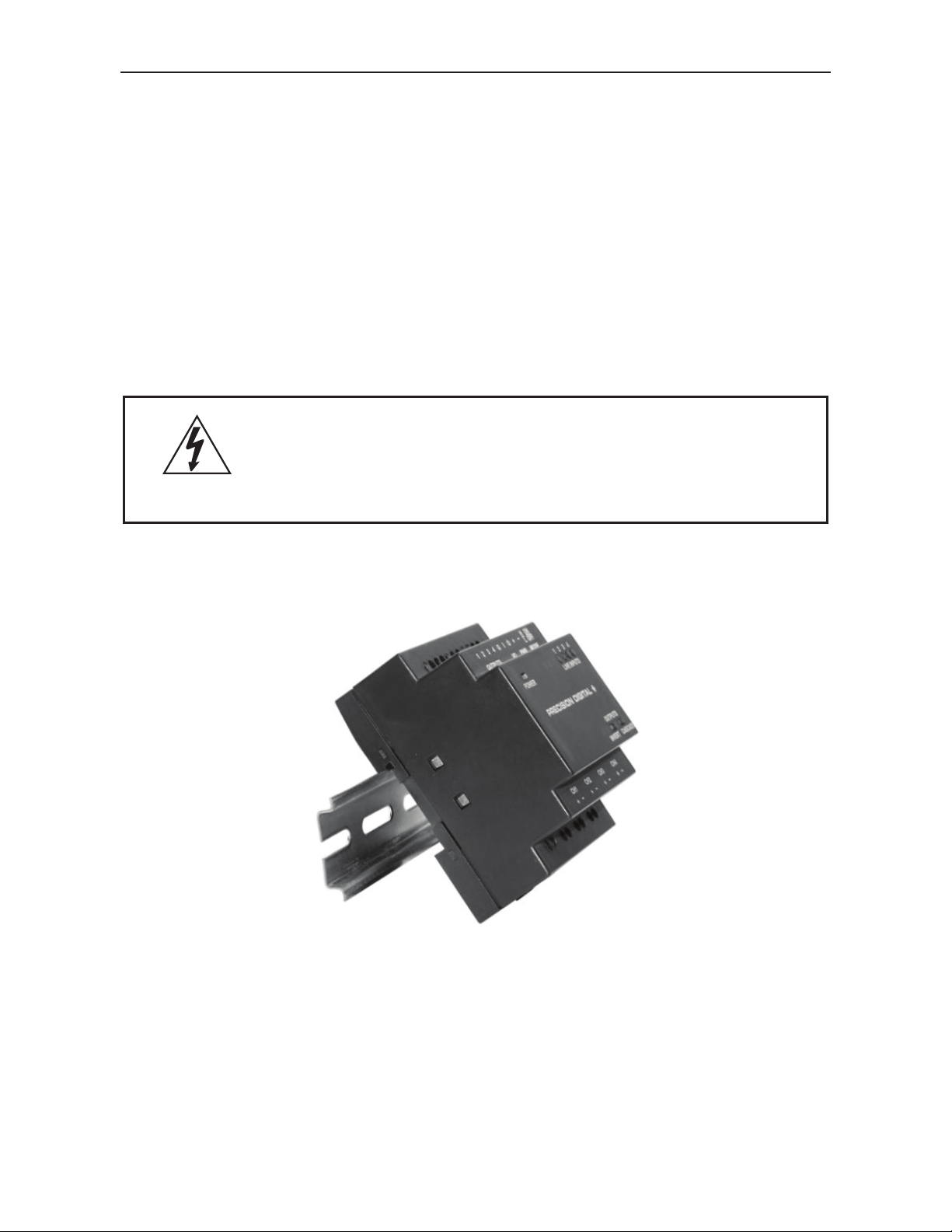
The converter may be snap-fit onto a DIN rail. The design of the
mounting tab allows for tool-free mounting.
1. Hook the upper part of the converter onto the DIN rail at the
desired location.
2. Press the converter flat onto the DIN rail. The mounting tab will
snap into position, securing the converter.
Find Quality Products Online at: [email protected]
www.GlobalTestSupply.com
9
Page 10
Model PDA1500 Logic Level Converter Instruction Manual
WARNING
Hazardous voltages exist within enclosure and at
wiring connections. Installation and service should
be performed only by trained service personnel.
Removing the Converter from the DIN Rail
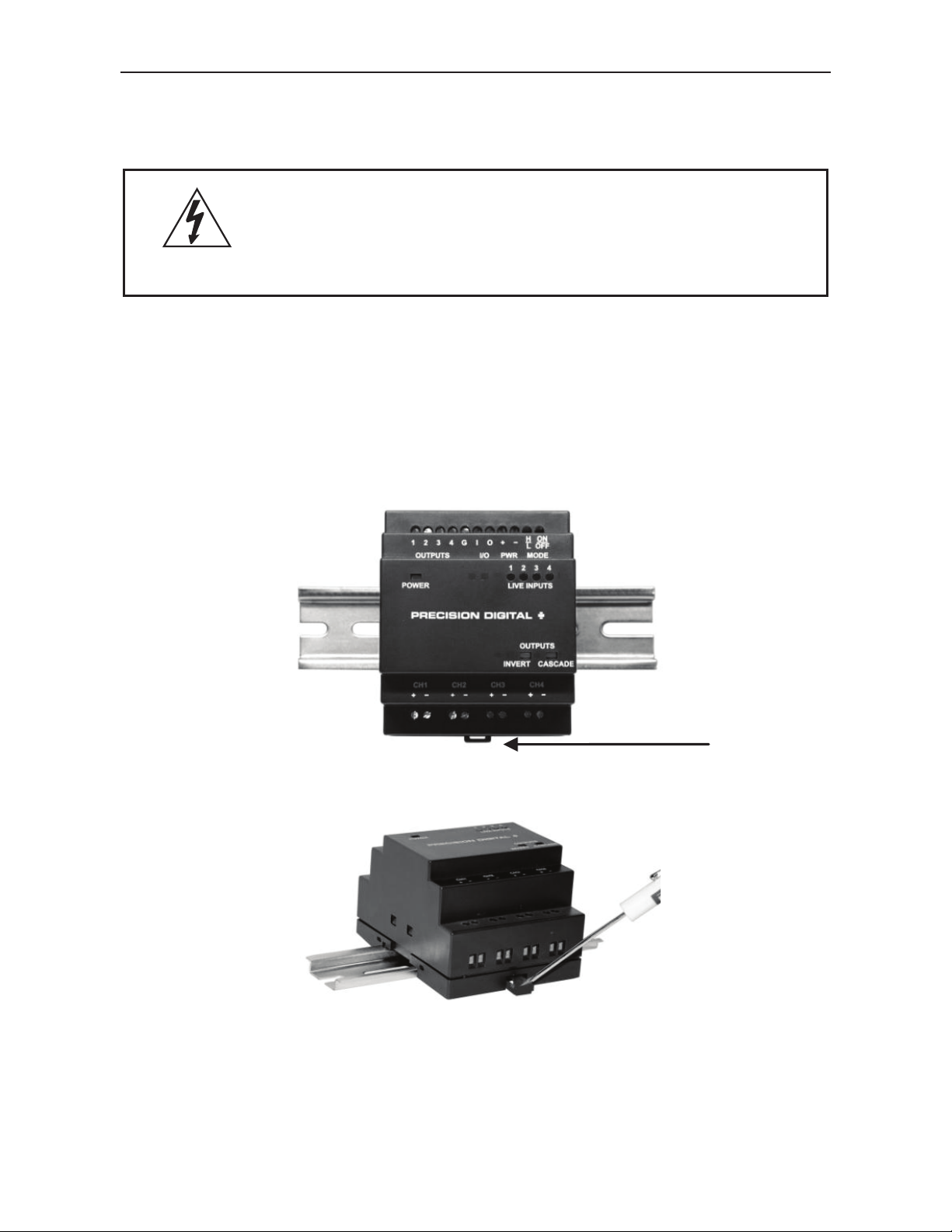
Removing the converter from the DIN rail requires the use of a small
slotted screwdriver or simil ar tool.
1. Be s
ure no high voltage is present on the input channel wires
by disconnecting power to those circuits.
2. Do not proceed while the converter is powered on.
3. Disconnect any wiring necessary to remove the converter.
4. Locate the DIN rail mounting tab on the lower side of the
converter. It is located just behind the high voltage input lines.
5. Insert a small slotted screwdriver or similar tool into the
mounting tab, and gently pull down on it.
6. While pulling down on the mounting tab, rotate the bottom of
the converter enclosure up until the top of the converter is
freed from the DIN ra
il
Find Quality Products Online at: [email protected]
www.GlobalTestSupply.com
10
Page 11
Model PDA1500 Logic Level Converter Instruction Manual
Caution
Use copper wire with 60°C or 60/75°C insulation for all
line voltage connections. Observe all safety regulations.
Electrical wiring should be performed in accordance with
all applicable national, state, and local codes to prevent
damage to the converter and ensure personnel safety.
WARNING
Hazardous voltages exist within enclosure and at
wiring connections. Installation and service should
be performed only by trained service personnel.
CONNECTIONS & SETUP
Wiring & Connections
All connections are made to fixed position screw terminal connectors
located on the top and bottom of the enclosure.
Find Quality Products Online at: [email protected]
www.GlobalTestSupply.com
11
Page 12
Model PDA1500 Logic Level Converter Instruction Manual
Group
Label
Description
OUTPUTS
1 (to 4)
Digital output 1 (to 4)
OUTPUTS
G
Digital output common
I/O
I
Multi-unit Cascade Mode input
I/O
O
Multi-unit Cascade Mode output
PWR
+
DC power positive terminal
PWR
–
DC power negative terminal
MODE
H/L
Location of Inverted Mode switch
MODE
ON/OFF
Location of Cascade Mode switch
CH1
(to CH4)
Channel 1 (to 4) high voltage input
positive
CH1
(to CH4)
Channel 1 (to 4) 1 high voltage input
negative
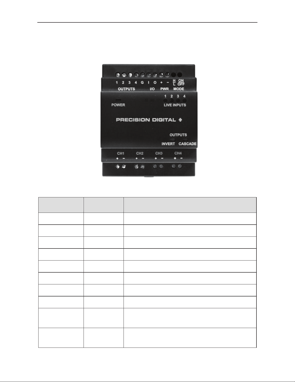
Connector Markings
Connector markings are printed on the front of the enclosure near each
terminal. These markings indicate the function of the connection
terminal next to the labeling.
Figure 1. Connector Markings
+
–
Find Quality Products Online at: [email protected]
www.GlobalTestSupply.com
12
Page 13
Model PDA1500 Logic Level Converter Instruction Manual
WARNING
Hazardous voltages exist within enclosure and at
wiring connections. Installation and service should
be performed only by trained service personnel.
Power Connections
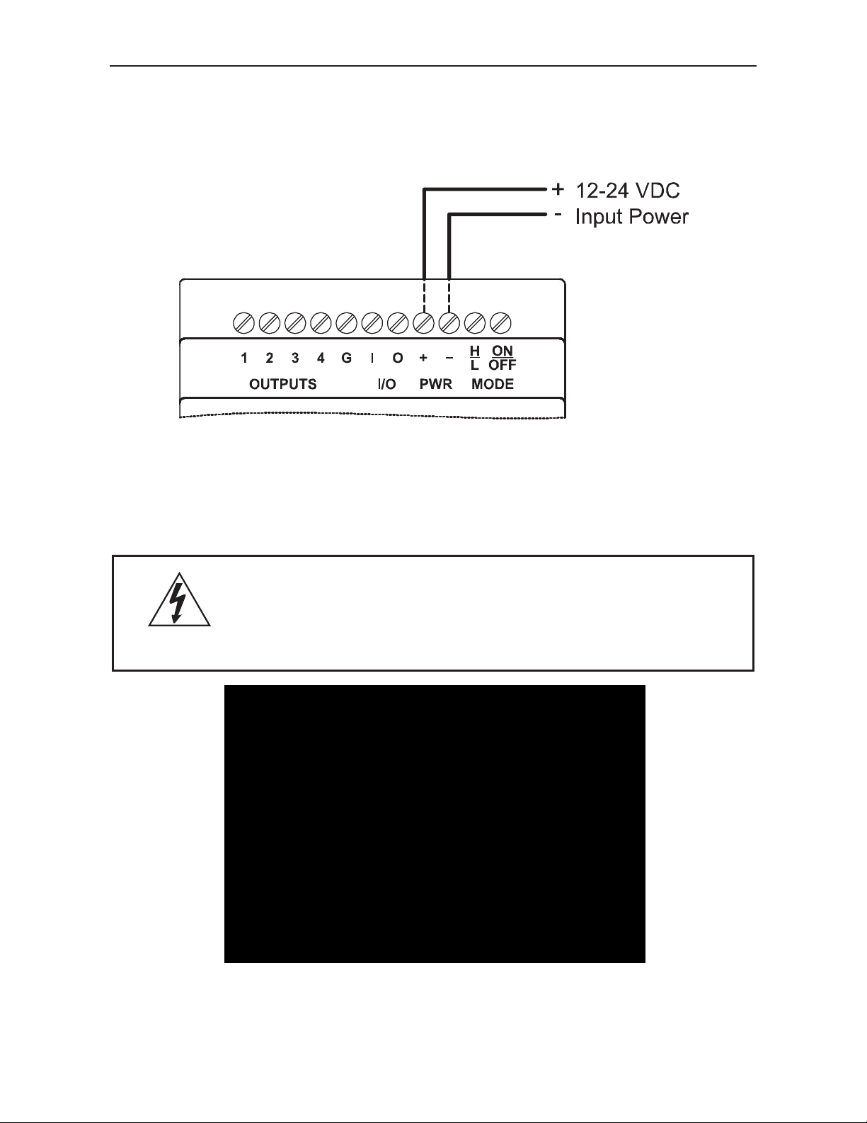
Power connections are made to the two terminals labeled PWR on
Figure 2. 12-24 VDC is applied with the polarity shown by the + and symbols.
Figure 2. Power Connections
Input Signal Connections
High voltage input channel 1-4 signal connections are made to the
terminals labeled CH1, CH2, CH3, and CH4 on Figure 3.
Figure 3. High Voltage Input Channel Connections
Find Quality Products Online at: [email protected]
www.GlobalTestSupply.com
13
Page 14
Model PDA1500 Logic Level Converter Instruction Manual
Digital Output Connections
Low voltage digital outputs 1-4 signal connections are made to the
terminals labeled OUTPUTS 1, 2, 3, 4, and G on Figure 4. The terminal
labeled G is the common for all four digital outputs.
For input devices with a + and – terminal for every input channel, output
terminal G will be connected to all negative digital input terminals.
Figure 4. Digital Output Connections
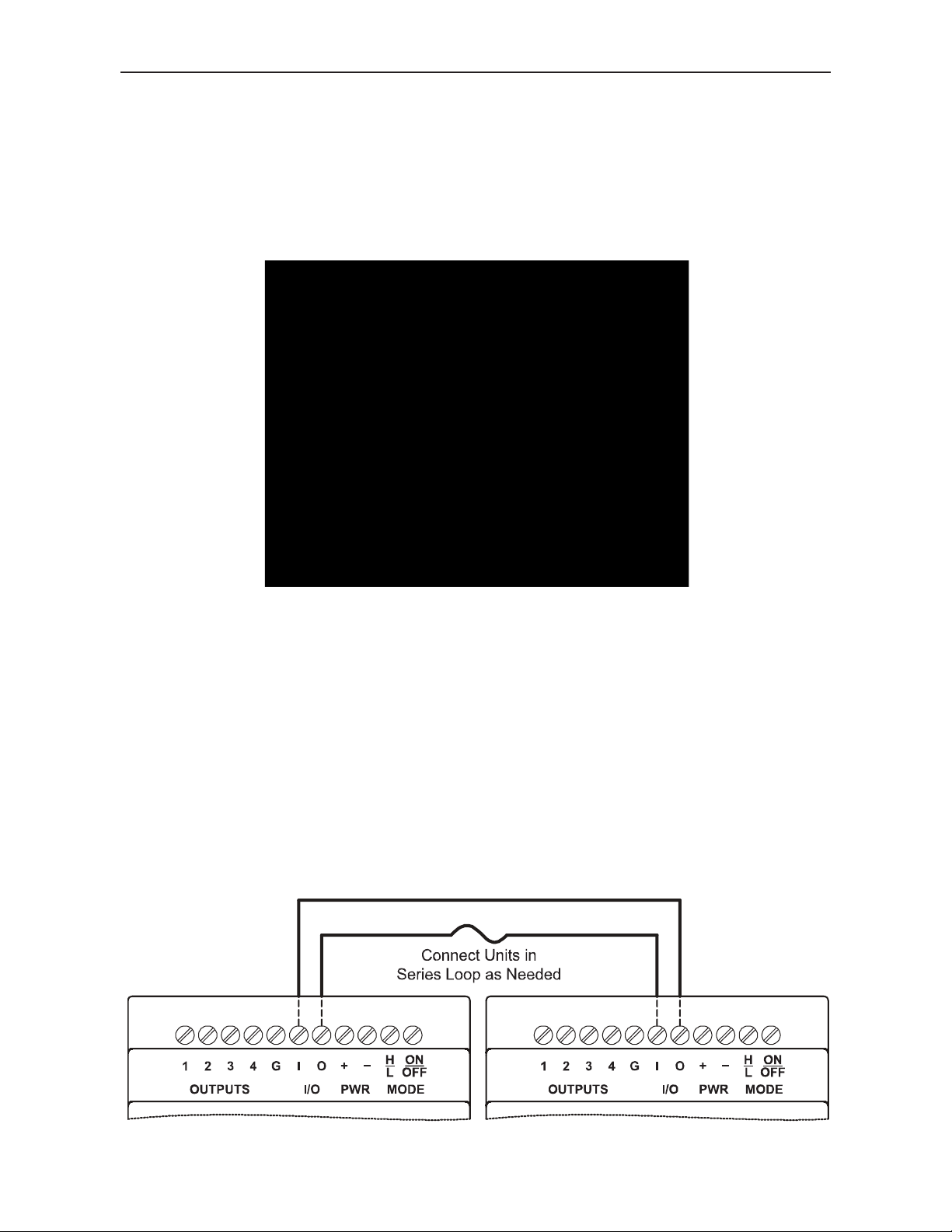
Cascade Mode Multiple Unit I/O Connections
When using Cascade Mode (see page 19), I/O terminals I and O shown
in Figure 5 may be used to link together multiple converters, and
provide additional inputs and outputs for monitoring. An unlimited
number of units may be connected in this way.
To connect multiple units in Cascade Mode, connect terminal O on the
first converter to the I terminal of the second. Continue to connect
converters in this way until the last converter’s O terminal is connected
to the first converters I terminal.
Figure 5. Cascade Mode Multiple Unit I/O Connections
14
Find Quality Products Online at: [email protected]
www.GlobalTestSupply.com
Page 15

Model PDA1500 Logic Level Converter Instruction Manual
Mode Selection Latching Pushbuttons
There are two latching pushbuttons located on the top of the unit within
the enclosure. These are located next to the ON/OFF and H/L labels,
inside the terminal connection openings. These pushbuttons are used to
enable Cascade Mode and/or Inverter Mode.
Normal/Cascade Mode ON/OFF Button
To activate Cascade Mode (see page 19), press the latching pushbutton
located in the terminal opening labeled MODE, ON/OFF.
Normal Mode operation is active when the button is in the forward
position. Cascade Mode is active when the button is latched into the
recessed position as shown below.
For information on Normal Mode operation, see page 18.
For information on Cascade Mode operation, see page 19.
Figure 6. Normal Mode ON/OFF (Cascade Mode) Switch
(Cascade Mode ON if recessed as shown.)
15
Find Quality Products Online at: [email protected]
www.GlobalTestSupply.com
Page 16

Model PDA1500 Logic Level Converter Instruction Manual
Output H/L Inverter Mode
The H/L latching pushbutton is used to invert the output states. For
example, in Normal Mode, when input channels CH1-CH4 detect high
voltage, the corresponding output will provide an active high. When high
voltage is not detected on an input, the corresponding output will
provide an active low signal.
This default output state may be inverted with the Output H/L button.
When the H/L button is latched into the recessed position as shown
below, the output condition will be inverted. When input channels CH1CH4 detect high voltage, the corresponding output will provide an active
low. When high voltage is not detected on an input, the corresponding
output will provide an active high signal.
Inverter Mode many be applied to Cascade outputs as well.
For information on Inverted Normal Mode operation, see page 18.
For information on Inverted Cascade Mode operation, see page 20.
Figure 7. Inverted H/L Switch Set to Low
(Active low output when input voltage present if recessed as
shown.)
16
Find Quality Products Online at: [email protected]
www.GlobalTestSupply.com
Page 17
Model PDA1500 Logic Level Converter Instruction Manual
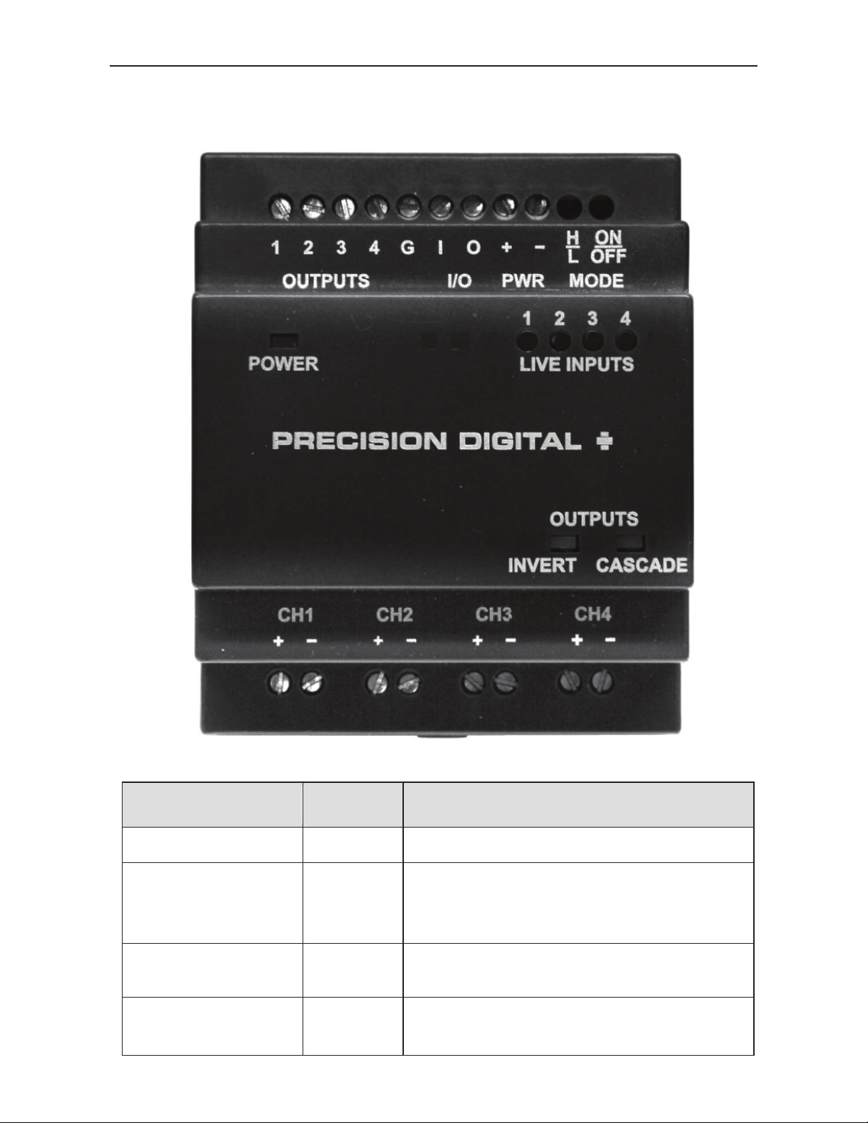
LED Indicator
Color
Description
POWER
Green
LED ON indicates unit is powered
LIVE INPUTS
(1
Red
LED ON indicates high voltage is
present on corresponding input
channel (CH1 – CH4)
INVERT
Yellow
LED ON if Inverted Mode is enabled
(low output when input high)
CASCADE
Yellow
LED ON if Cascade Mode is
enabled
LED INDICATORS
- 4)
Find Quality Products Online at: [email protected]
www.GlobalTestSupply.com
17
Page 18
Model PDA1500 Logic Level Converter Instruction Manual
Input
LIVE
s
MODE Switch
Positions
OUTPUTS
(1-4)
H/L
ON/OFF
High
On (Red)
Off
Off
High
Low
Off
Off
Off
Low
On (Red)
Recessed
(On)
Off
Recessed
(On)
Off
OPERATION
The PDA1500 High Voltage AC/DC to Logic Level Converter accepts up
to four high voltage input signals and outputs a TTL logic (5 V) signal
representative of each input’s status (whether high voltage is present or
not).
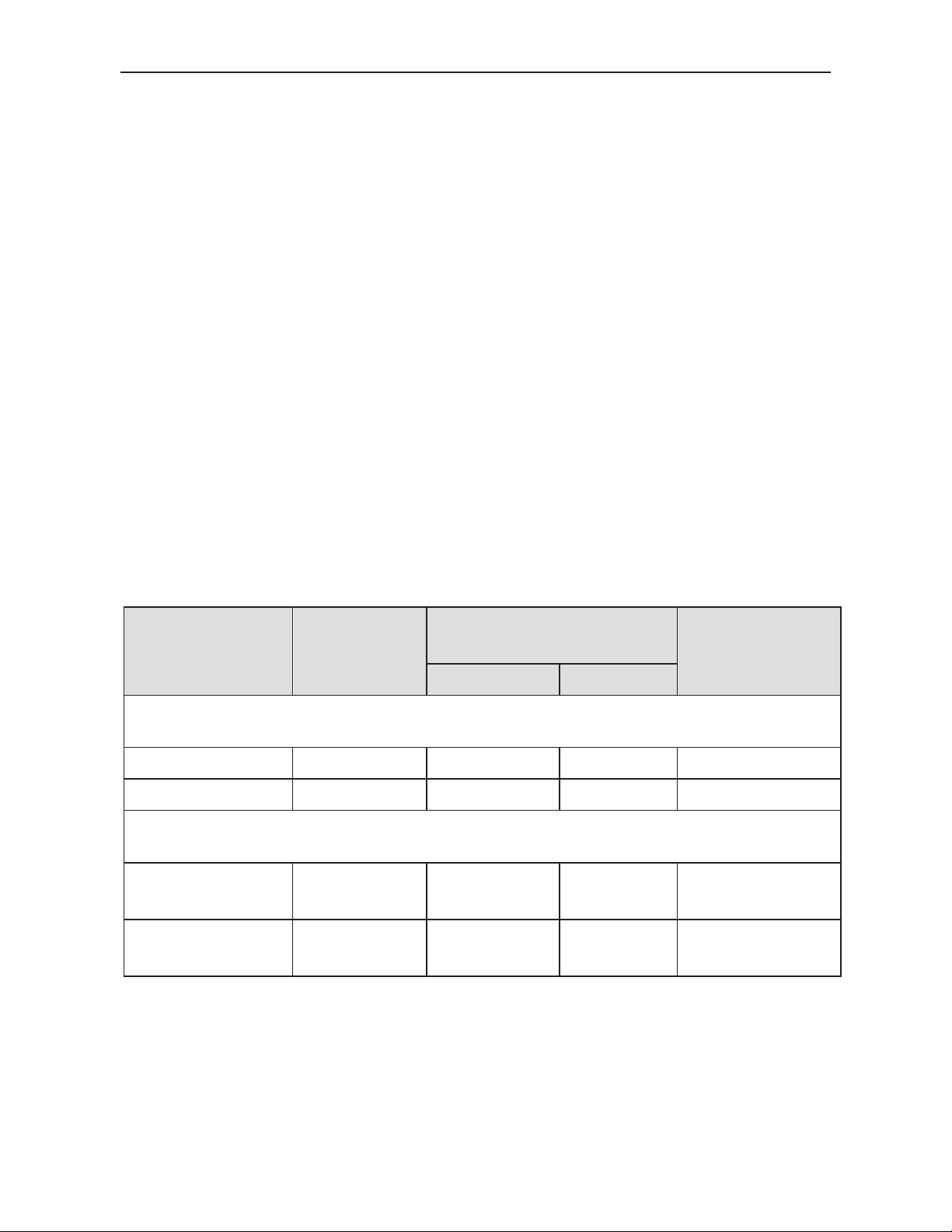
Normal Mode
In Normal Mode operation, the converter detects the presence of high
voltage on input channels CH1 to CH4. If high voltage is present, the
corresponding output 1 to 4 will be high. If voltage is below the detection
range, the corresponding output will be low.
Inverted Mode
In Inverted Mode operation, the state of all outputs is the inverse of what
they would be in Normal Mode. The converter detects the presence of
high voltage on input channels CH1 to CH4. If high voltage is present on
an input channel, the corresponding output 1 to 4 will be low. If voltage
is below the detection range on an input channel, the corresponding
output will be high.
Table 1. Normal and Inverse Operation Logic
Voltage
(CH1-CH4)
1
INPUTS
State
LED
Normal Mode
Inverted Mode
High
Low Off
1. Input “High” for the PDA1500-115 is 85-130 VAC or VDC.
Input “High” for the PDA1500-230 is 185-265 VAC or VDC.
Input “Low” is any voltage lower than the “High” range.
2
Low
High
2. Output “High” is 4.4 to 5.0 VDC.
Output “Low” is 0 to 0.33 VDC
Find Quality Products Online at: [email protected]
www.GlobalTestSupply.com
18
Page 19
Model PDA1500 Logic Level Converter Instruction Manual
Input
Channel
Input
Voltage1
(CH1-CH4)
LIVE
OUTPUTS
(1-4)
CH1
High
On (Red)
High
CH1 & CH2
CH2
High
On (Red)
Low
CH2 & CH3
CH3
Low
Off
High
CH3 & CH4
CH4
Low
Off
High
N/A
Input
Channel
Input
Voltage1
(CH1-CH4)
LIVE
OUTPUTS
(1-4)
CH1
High
On (Red)
Low
CH1 & CH2
CH2
Low
Off
High
CH2 & CH3
CH3
Low
Off
High
CH3 & CH4
CH4
Low
Off
High
N/A
Cascade Mode
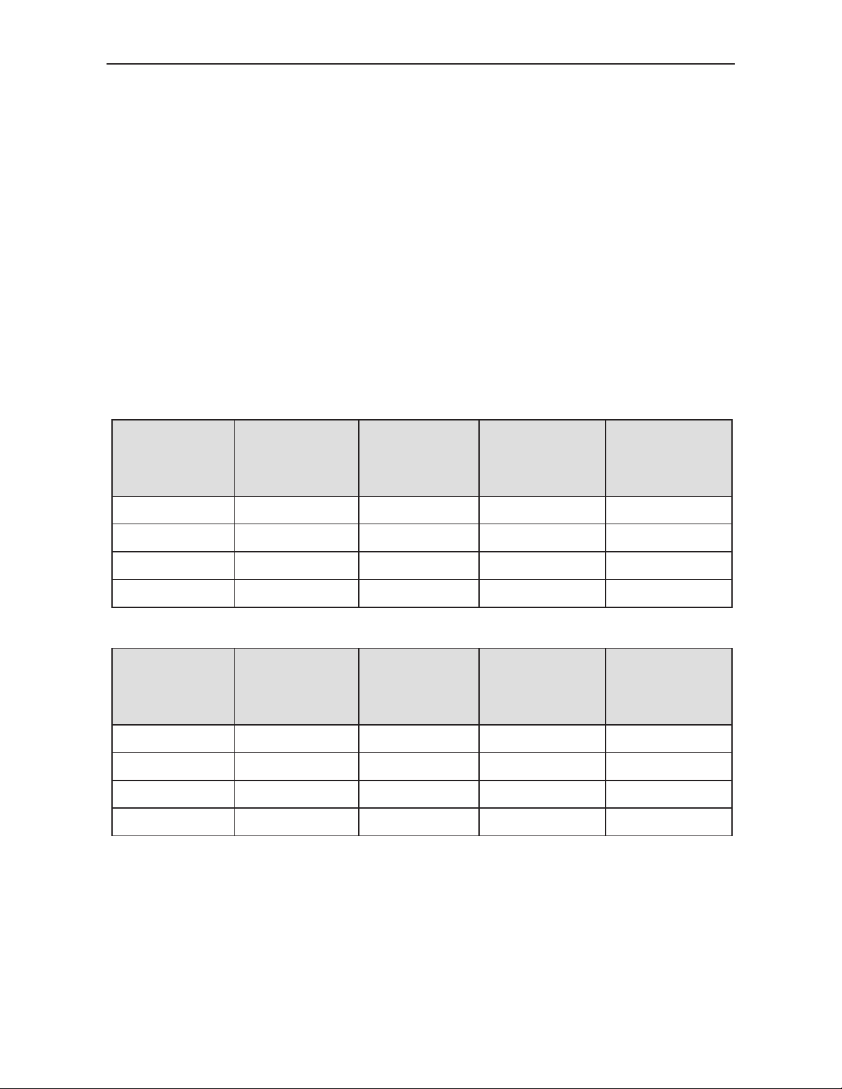
Cascade Mode is a special operation mode used for the monitoring of
high voltage interlocks where one failure causes a failure of all
monitoring points further down in the system. Examples of this include
the many interlocks on boiler systems, where a single failure can cause
a cascade of failures later in the system. Cascade Mode will indicate the
single point of failure in these ser ie s sy ste ms.
Cascade mode provides a digital output alarm state if the corresponding
input channel is active, but the next subsequent input channel is
inactive. This can be used to identify the single point of system failure,
without indicating every alarm state throughout the linked series
interlock system.
Cascade mode utilizes exclusive NOR (inverting OR) logic.
Table 2. Cascade Mode Operation Logic Example 1
INPUTS
LED
State
2
XNOR
Logic
Table 3. Cascade Mode Operation Logic Example 2
INPUTS
State
2
XNOR
Logic
LED
1. Input “High” for the PDA1500-115 is 85-130 VAC or VDC.
Input “High” for the PDA1500-230 is 185-265 VAC or VDC.
Input “Low” is any voltage lower than the “High” range.
2. Output “High” is 4.4 to 5.0 VDC <– fixed extra space here.
Output “Low” is 0 to 0.33 VDC
Find Quality Products Online at: [email protected]
www.GlobalTestSupply.com
19
Page 20
Model PDA1500 Logic Level Converter Instruction Manual
Input
Channel
Input
Voltage1
(CH1-CH4)
LIVE
OUTPUTS
(1-4)
XOR Logic
CH1
High
On (Red)
Low
CH1 & CH2
CH2
High
On (Red)
High
CH2 & CH3
CH3
Low
Off
Low
CH3 & CH4
CH4
Low
Off
Low
N/A
Input
Channel
Input
Voltage1
(CH1-CH4)
LIVE
OUTPUTS
(1-4)
XOR Logic
CH1
High
On (Red)
High
CH1 & CH2
CH2
Low
Off
Low
CH2 & CH3
CH3
Low
Off
Low
CH3 & CH4
CH4
Low
Off
Low
N/A
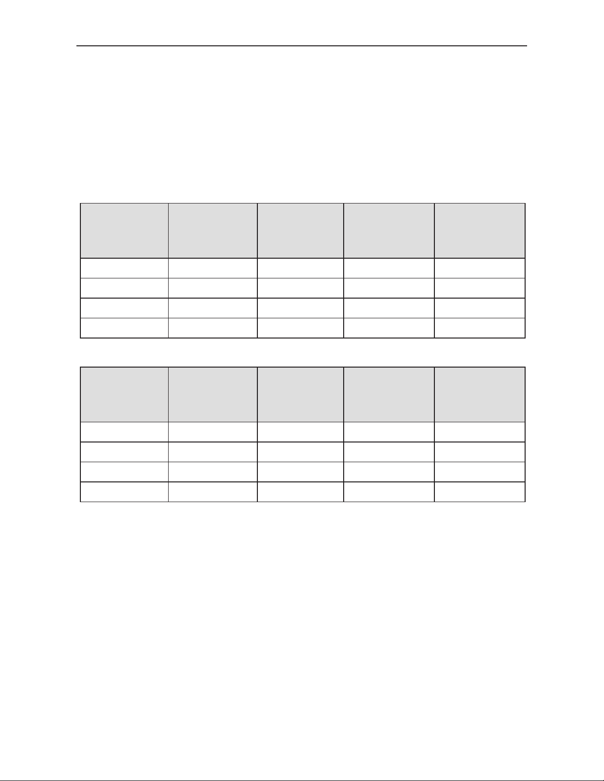
Inverted Cascade Mode
Inverted Mode may be applied to Cascade Mode. When the H/L
pushbutton is latched in the recessed position, Inverted Mode is active.
The outputs behave using the same logic as in Cascade Mode, but the
output states are all inverted.
This makes the Cascade Mode output function using exclusive OR
(XOR) logic.
Table 4. Inverted Cascade Mode Operation Logic Example 1
INPUTS
State
2
LED
Table 5. Inverted Cascade Mode Operation Logic Example 2
INPUTS
State
2
LED
1. Input “High” for the PDA1500-115 is 85-130 VAC or VDC.
Input “High” for the PDA1500-230 is 185-265 VAC or VDC.
Input “Low” is any voltage lower than the “High” range.
2. Output “High” is 4.4 to 5.0 VDC.
Output “Low” is 0 to 0.33 VDC
Find Quality Products Online at: [email protected]
www.GlobalTestSupply.com
20
Page 21
Model PDA1500 Logic Level Converter Instruction Manual
Unit
#
Input
Channel
Input
Voltage1
(CH1-CH4)
LIVE
INPUTS
LED
OUTPUTS
(1-4)
XNOR
(Unit #)
1
CH1
On (Red)
CH1 (1) &
CH2 (1)
1
CH2
On (Red)
CH2 (1) &
CH3 (1)
1
CH3
On (Red)
CH3 (1) &
CH4 (1)
1
CH4
On (Red)
CH4 (1) &
CH1 (2)
2
CH1
Off
CH1 (2) &
CH2 (2)
2
CH2
Off
CH2 (2) &
CH3 (2)
2
CH3
Off
CH3 (2) &
CH4 (2)
2
CH4
Off
CH4 (2) &
CH1 (1)
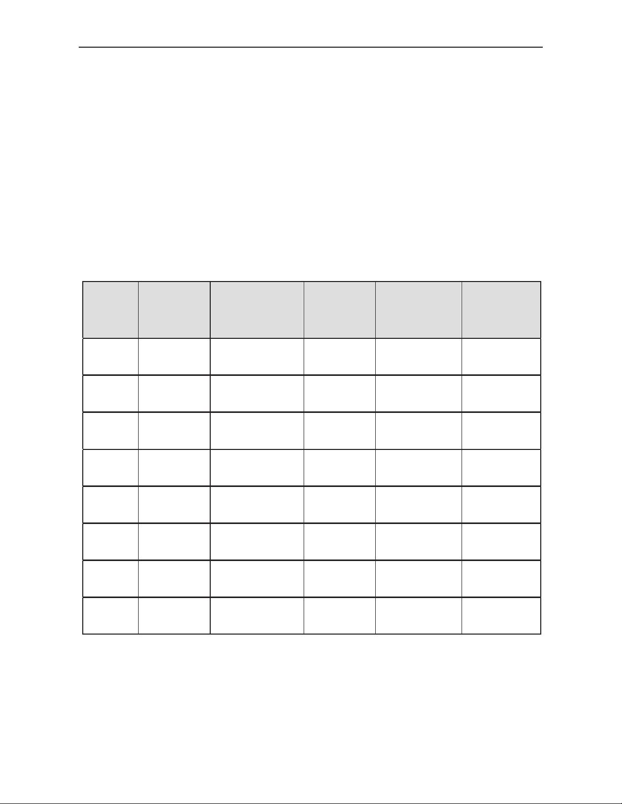
Multiple Unit Cascade Mode
Cascade Mode logic may be combined across multiple Logic Level
Converters to monitor more than 3 alarm outputs (or 4 inputs). When
wired together, output four (4) of a Logic Level Converter will monitor
input CH4 and CH1 of the next Logic Level Converter wired in series
with it.
For information on how to connect units for Cascade Mode, see
Cascade Mode Multiple Unit I/O Connections on page 14.
Inverted Cascade Mode will also work across multiple units.
Multiple unit Cascade Mode may be used across an unlimited number
of units.
Table 6. Multiple Unit Cascade Mode Operation Logic
High
High
High
High
Low
Low
Low
State
Low
Low
Low
High
Low
Low
Low
2
Logic
Low
Low
1. Input “High” for the PDA1500-115 is 85-130 VAC or VDC.
Input “High” for the PDA1500-230 is 185-265 VAC or VDC.
Input “Low” is any voltage lower than the “High” range.
2. Output “High” is 4.4 to 5.0 VDC.
Output “Low” is 0 to 0.33 VDC
Find Quality Products Online at: [email protected]
www.GlobalTestSupply.com
21
Page 22

Model PDA1500 Logic Level Converter Instruction Manual
MOUNTING DIMENSIONS
Units: in [mm]
Figure 8. Dimensions - Front View
Figure 9. Dimensions - Side View
22
Find Quality Products Online at: [email protected]
www.GlobalTestSupply.com
Page 23

Model PDA1500 Logic Level Converter Instruction Manual
Symptom
Check/Action
No LEDs are ON or outputs
present
Check power at power connector
Digital outputs behave in an
unexpected manner
Check the status of the Inverted Mode
(H/L) button and Cascade Mode
(ON/OFF) button
When high voltage is present on
an input, no LIVE INPUT LED or
output condition changes
Check the model number and verify the
input voltage range
Other symptoms not described
above
Call Technical Support for
assistance.
TROUBLESHOOTING
The rugged design and simple configuration of the Logic Level
Converter should make it unusual for the installer or operator to refer to
this section of the manual. However, should a problem be encountered,
the following tips may prove useful.
Find Quality Products Online at: [email protected]
www.GlobalTestSupply.com
23
Page 24

Model PDA1500 Logic Level Converter Instruction Manual
LIM1500_A
6/14
Find Quality Products Online at: [email protected]
www.GlobalTestSupply.com
 Loading...