

Page 1

PDA10 04, PDA1011 & PDA1044 ProroVuu Expansion Modules
Instruction Manual
PDA1011
PDA1004
4 Relays Module
• External Modules Add Functionality to ProVu Meters
• Four SPST Relays Module
• Dual 4-20 mA Output (for select models) Module
• Four Digital Inputs & 4 Digital Outputs Module
Dual 4-20 mA
Output Module
PDA1044
Digital I/O Module
Introduction
Use these external expansion modules to add
functionality to ProVu meters in the eld. They can be
added at any time and are easy-to-install.
The PDA1004 relays module includes 4 Form A
(SPST) relays rated at 3 Amps and when added to a
meter that has 4 on-board relays results in a system
with 8 relays.
The PDA1011 dual 4-20 mA output module can only
be used with the dual input meters, Modbus scanners,
and the high voltage and current meters. Connecting
one of these modules to one of these meters that has
the on-board 4-20 mA output, results in a meter with
three 4-20 mA outputs.
The PDA1044 digital I/O module has four digital inputs
and four digital outputs per module and two may be connected
together to achieve a system with eight I/O. External digital
inputs function similarly to the F4 digital
input. They can be configured to trigger events
(i.e. acknowledge/reset alarms, reset total, reset max
and/or min values, disable/enable all relays, etc.),
provide specific menu access, or mimic front keys.
Digital outputs can be used to drive solid state relays,
or as inputs to other alarm or control devices
These expansion modules can be used individually
or in systems with other modules and serial adapters.
For instance, a system consisting of two 4-20 mA
inputs, three 4-20 mA outputs, eight relays, eight
digital inputs, eight digital outputs and RS-485 could
be congured using these items:
(1) PD6060-6R7 Dual Input Process Meter
(1) PDA1004 Relays Module
(1) PDA1011 Dual 4-20 mA Out Module
(2) PDA1044 Digital I/O Module
(1) PDA1485 Serial Adapter
MeterView Pro software can be used to congure
these modules when they are connected to meters.
Find Quality Products Online at: [email protected]
www.GlobalTestSupply.com
Page 2
PDA1004, PDA1011 & PDA1044 ProroVuu Expansion Modules
CAUTION
WARNING
Instruction Manual
Disclaimer
The information contained in this document
is subject to change without notice. Precision
Digital makes no representations or warranties
with respect to the contents hereof, and
specically disclaims any implied warranties
of merchantability or fitness for a particular
purpose.
• Read complete instructions prior to installation and
operation of the meter.
S
• Risk of electric shock or personal injury.
• These products are not recommended for life support
applications or applications where malfunctioning
could result in personal injury or property loss.
Anyone using these products for such applications
does so at his/her own risk. Precision Digital
Corporation shall not be held liable for damages
resulting from such improper use.
Limited Warranty
Precision Digital Corporation warrants these
products against defects in material or
work
manship for the specied period under
“Specications” from the date of shipment from the
factory. Precision Digital’s liability under this limited
warranty shall not exceed the purchase value,
repair, or replacement of the defective unit.
Registered Trademarks
All trademarks mentioned in this document are the
property of their respective owners.
© 2020 Precision Digital Corporation.
All rights reserved.
Ordering Information
Model Description
PDA1004 4 Relays Expansion Module
PDA1011 Dual 4-20 mA Output Module
PDA1044 4 Digital Inputs & 4 Digital Outputs Module
WARNING
Cancer and Reproductive Harm
Table of Contents
Introduction .......................................................................................................................................1
Ordering Information ........................................................................................................................2
Specications ...................................................................................................................................3
Installation .........................................................................................................................................3
Mounting Instructions ...................................................................................................................... 5
Table of Figures
Figure 1. M-Link Connector Location on the Meter ......................................................................4
Figure 2. PDA1044 Jumper Location ............................................................................................. 4
Figure 3. External Relays Module Connections ...........................................................................4
Figure 4. Dual Analog Output Module Connections ....................................................................4
Figure 5. Digital I/O Module Connections .....................................................................................4
Figure 6. DIN Rail Clips Mounted to Expansion Module ............................................................... 5
Figure 7. Hinge & Latch End of DIN Rail Clip .................................................................................5
Figure 8. DIN Rail Clips Mounted to Module ................................................................................. 5
Figure 9. Examples of Clips Mounted to Modules .........................................................................5
Figure 10. Mounting the DIN Rail with 2 #10 Pan Head Screws ................................................... 5
Figure 11. Example of Modules Mounted to DIN Rail ....................................................................5
Figure 12. Snapping the Module to the DIN Rail ............................................................................5
Accessories
Model Description
PDA1002 DIN Rail Mounting Kit for Two Expansion
Modules
2
Find Quality Products Online at: [email protected]
www.GlobalTestSupply.com
Page 3

PDA1004, PDA1011 & PDA1044 ProroVuu Expansion Modules
WARNING
WARNING
Instruction Manual
Specications
Except where noted all specications apply to
operation at +25°C.
General (All models)
Power ProVu meter M-LINK connection
Cable Standard CAT5e cable; provided with
Connectors Meter End: RJ45 (two);
System Any combination of:
Serial Adapter
Compatibility
Tightening
Torque
Enclosure ABS-94HB material, UL94HB
Overall
Dimensions
Warranty
module.
Note: To ensure optimum performance
use only supplied cables.
identical and Interchangeable.
Field End: Removable screw terminal
blocks that accept 12 to 22 AWG wire.
(1) PDA1004 Relays Module
(1) PDA1011 Dual 4-20 Output Module
(2) PDA1044 Digital I/O Module
(1) Serial Adapter
Expansion modules may be used with
PDA1485, PDA1232, or PDA8008
Screw terminal connectors:
5 lb-in (0.56 Nm)
(Flame-Class Rating)
2.3" x 0.9" x 3.6"
58 mm x 23 mm x 92 mm (W x H x D)
3 years parts & labor.
PDA1044 Digital Input &
Output Expansion Module
Channels 4 digital inputs & 4 digital outputs per
Digital Input
Logic High
Digital Input
Logic Low
Digital Output
Logic High
Digital Output
Logic Low
Source
Current
Sink Current
+5 V Terminal To be used as pull-up for digital inputs
• DO NOT use +5 V terminal (pin 1) to power external
devices.
Weight
module
3 to 5 VDC
0 to 1.25 VDC
3.1 to 3.3 VDC
0 to 0.4 VDC
10 mA maximum output current
1.5 mA minimum input current
only. Connect normally open
pushbuttons across +5 V & DI 1- 4.
2.2 oz (62 g)
Installation
PDA1004 4 Relays Expansion Module
Relays Four; Form A (SPST); Rated 3 A @
Weight 2.4 oz (68 g)
30 VDC and 125/250 VAC for resistive
loads. 1/14 HP @ 125/250 VAC for
inductive loads.
PDA1011 Dual 4-20 mA Output Module
Compatibility PD6060, PD6262, PD6363, PD6400,
Accuracy ± 0.1% of span ± 0.004 mA
Scaling
Range
Temperature
Drift
Output Loop
Resistance
Isolation The dual 4-20 mA outputs are not
Weight 1.8 oz (51 g)
PD6080, PD6081, PD6088, PD6089
3.000 to 23.000 mA for any display
range
0.4 µA/°C max from 0 to 65°C ambient
0.8 µA/°C max from -40 to 0°C ambient
Note: Analog output drift is separate
from input drift.
Power supply
24 VDC 10 Ω 700 Ω
35 VDC
(external)
isolated from each other or from the
system ground.
Minimum Maximum
100 Ω 1200 Ω
There is no need to remove the expansion module
from its case to complete the installation, wiring,
or setup of the unit. The expansion module may
be programmed using the meter’s buttons or via
MeterView Pro software.
• Connect the expansion module to the meter before
applying power to the meter.
• Do not connect or disconnect the expansion module
with the power on.
• Do not connect any equipment other than Precision
Digital’s expansion modules, cables, or meters to
the RJ45 MLINK connector. Otherwise damage will
occur to the equipment and the meter.
3
Find Quality Products Online at: [email protected]
www.GlobalTestSupply.com
Page 4
PDA1004, PDA1011 & PDA1044 ProroVuu Expansion Modules
CAUTION
1 2
RLY5 RLY6 RLY7 RLY8
3 4 5 6 7 8
NO C NO C NO C NO C
1 2 3 4 5 6
+5 I1 I2 I3 I4 O1
7 8
O2 O3
9 10
O4 G
DI 1-4 DO 1-4
5 VDC GND
Instruction Manual
Expansion Module Connections
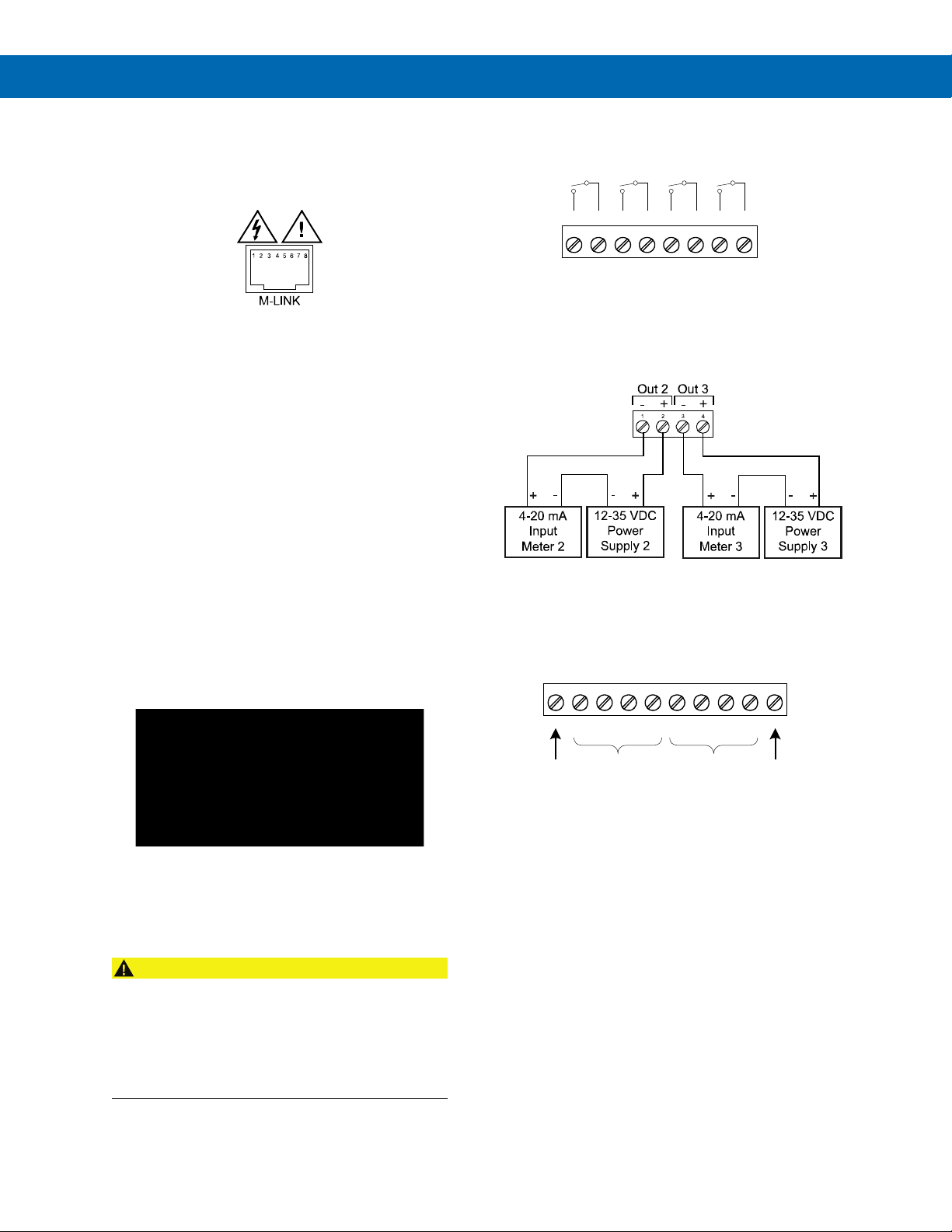
The relay, dual-analog output, and digital I/O
expansion modules PDA1004, PDA1011, and
PDA1044 are connected to the meter using a CAT5e
cable provided with each module (see Figure 1).
Figure 1. M-Link Connector Location on the Meter
The two RJ45 connectors on the expansion modules
are identical and interchangeable; one is used to
connect the meter to the module and the other is used
to connect the module to an additional module.
PDA1011 4-20 mA Output Conguration
The following must be performed prior to powering the
meter for the meter to recognize the PDA1011 dual
analog output module:
1. Connect the M-Link connector on the module to
the meter.
2. Wire and power each analog output being used.
Power should be provided by a DC supply
different than the one powering the meter.
PDA1004 Relays Connections
Connections are made to an eight-position removable
screw terminal connector.
Figure 3. External Relays Module Connections
PDA1011 Dual Analog Output Connections
Connections are made to a four-position removable
screw terminal connector.
Figure 4. Dual Analog Output Module Connections
PDA1044 Digital I/O Conguration
The jumper located between the RJ45 connectors of
the PDA1044 (see Figure 2) must be removed on the
second digital I/O module in order for the system to
recognize it as module #2.
Figure 2. PDA1044 Jumper Location
Terminal Block Connections
All connections are made to removable screw terminal
connectors located at the front of the module.
• Use copper wire with 60°C or 60/75°C insulation
for all line voltage connections. Observe all safety
regulations. Electrical wiring should be performed
in accordance with all applicable national, state,
and local codes to prevent damage to the meter and
ensure personnel safety.
PDA1044 Digital I/O Connections
Connections are made to a ten-position removable
screw terminal connector.
Figure 5. Digital I/O Module Connections
Find Quality Products Online at: [email protected]
4
www.GlobalTestSupply.com
Page 5

PDA1004, PDA1011 & PDA1044 ProroVuu Expansion Modules
Instruction Manual
Mounting Instructions
Step 1: Mounting the DIN Rail Clips to Module
Place the expansion module on a at surface with the
bottom surface facing up. The bottom surface can be
identied as the surface closest to the locking tab slot on the
modular connector as shown in Figure 6.
Locking Tab Slot
Figure 6. DIN Rail Clips Mounted to Expansion Module
Peel the protective layer off the adhesive tape on the bottom
of one of the mounting clips. With the hinge end of the clip,
as shown in Figure 7, facing the end of the module with the
communications connector, align the clip along the long
(side) edge of the module and centered lengthwise within the
at surface of the module as shown in Figure 8.
Hinge End Latch End
Step 2: Mounting the DIN Rail to a Surface
The expansion modules, serial adapters and serial
converters weigh approximately 1.5 oz (42 grams) each so
the mounting hardware does not need to be overly strong.
We recommend two #10 pan head screws as shown in
Figure 10, but only because they best accommodate the
slots in the DIN rail. The amount of strain the wiring might
place on the module mounting needs to be considered also.
In many cases, DIN rail with double-sided tape might be
acceptable, although not recommended in areas of high
vibration or extreme hot or cold temperatures.
Figure 10. Mounting the DIN Rail with 2 #10 Pan Head
Screws
When choosing a location to mount the DIN rail, keep in mind
that wires will be entering both ends of the modules as shown
in Figure 11. Leave enough room on either end of module to
allow for wire routing to prevent undue stress placed on the
module’s connectors and mounting clips. The DIN rail may be
mounted on any vertical or horizontal mounting surface.
Figure 7. Hinge & Latch End of DIN Rail Clip
Figure 8. DIN Rail Clips Mounted to Module
Firmly press down on the clip for 10 seconds. Repeat this
procedure on the opposite side. Once the clips are properly
installed, the modules with clips mounted should look similar
to one or both of the modules pictured in Figure 9. While
the adhesive is initially quite strong, this strength improves
signicantly over a period of approximately 12 hours.
Figure 11. Example of Modules Mounted to DIN Rail
Step 3: Mounting Modules to the DIN Rail
To mount modules to a DIN rail, rst locate the approximate
desired position to place the module on the DIN rail, then
hook the hinge end of the mounting clip to the edge of the
DIN rail as shown in Figure 12. Next lower the opposite
“latch end” of the clip onto the rail. Press down on the
module until the latch end snaps in place.
Figure 12. Snapping the Module to the DIN Rail
A typical installation will look like Figure 13 once modules are
mounted to the DIN rail.
Figure 9. Examples of Clips Mounted to Modules
Find Quality Products Online at: [email protected]
www.GlobalTestSupply.com
Step 4: Connections
After mounting the device(s), refer to the Instruction Manual
for each module for proper connections and operation.
5
 Loading...