

Page 1
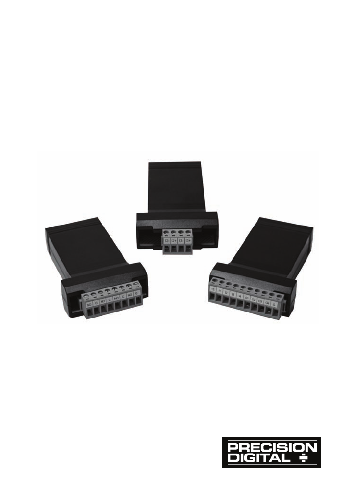
PDA1004, PDA1011, & PDA1044
Instruction
Relay, Analog Output, and Digital I/O
Expansion Modules
Manual
www.GlobalTestSupply.com
Page 2
PROVU® Expansion Modules Instruction Manual
Disclaimer
The information contained in this document is subject to change
without notice. Precision Digital makes no representations or warranties with respect to the contents hereof and specifically disclaim
any implied warranties of merchantability or fitness for a particular
purpose.
!
CAUTION: Read complete
instructions prior to installation and operation of the
module.
Expansion modules DO NOT contain internal jumpers or switches.
Hazardous voltages exist within enclosure.
Installation and service should be performed only by
WARNING!
WARNING!
trained service personnel.
Do not connect or disconnect the expansion module
with the power on!
WARNING: Risk of
electric shock or
personal injury.
Limited Warranty
Precision Digital Corporation warrants this product against defects in
material or workmanship for the specified period under “Specifications” from the date of shipment from the factory. Precision Digital’s
liability under this limited warranty shall not exceed the purchase
value, repair, or replacement of the defective unit.
Registered Trademarks
All trademarks mentioned in this document are the property of their respective owners.
© 2010-2017 Precision Digital Corporation. All rights reserved.
2
www.GlobalTestSupply.com
Page 3

PROVU® Expansion Modules Instruction Manual
Table of Contents
INTRODUCTION ------------------------------------------------------------ 3
Accessories ------------------------------------------------------------------------ 3
SPECIFICATIONS ---------------------------------------------------------- 4
General (applicable to all models) ------------------------------------------ 4
PDA1004 4-Relay Expansion Module -------------------------------------- 4
PDA1011 Dual Isolated 4-20 mA Output Module ----------------------- 4
PDA1044 Digital Input & Output Expansion Module ------------------ 5
INSTALLATION ------------------------------------------------------------- 5
Expansion Module Connections -------------------------------------------- 6
PDA1011 Configuration ------------------------------------------------------- 6
PDA1044 Configuration ------------------------------------------------------- 6
Terminal Block Connections ------------------------------------------------- 7
INTRODUCTION
These external expansion modules add functionality to the PROVU in the
field. They can be added at any time and are easy-to-install.
Add a 4-relay expansion module, and/or up to two I/O modules. The
PD6060, PD6080, PD6081, PD6088, PD6089, PD6262, PD6363, and
PD6400 P
items for these modules do not appear until the module is connected, simplifying the basic menu.
The relay module consists of four 3 amp Form A (SPST) relays. The analog
output module consists of two 4-20 mA outputs. Both are configured for
functions similar to the P
The I/O module has four digital inputs and four digital outputs per module.
External digital inputs function similarly to the F4 digital input on most
ROVU models. They can be configured to trigger events (i.e.
P
acknowledge/reset alarms, reset max and/or min values, disable/enable all
output relays), provide specific menu access, or mimic front keys. Digital
outputs can be used to remotely monitor alarm relay states, or the states of
a variety of actions and functions executed by the meter.
Accessories
ROVU meters may add an additional 2 analog outputs. The menu
ROVU onboard outputs.
Model Description
PDA1002 DIN-rail mounting kit for two expansion modules
PDA1200 Meter copy cable
PDA1232 RS-232 serial adapter
PDA1485 RS-422/485 serial adapter
PDA8008 USB Serial Adapter
3
www.GlobalTestSupply.com
Page 4

PROVU® Expansion Modules Instruction Manual
SPECIFICATIONS
Except where noted all specifications apply to operation at +25°C.
General (applicable to all models)
POWER ProVu meter M-LINK connection
Standard CAT5e cable; provided with module.
CABLE
CONNECTORS
TIGHTENING
TORQUE
ENCLOSURE ABS-94HB material, UL94HB (Flame-Class Rating)
OVERALL
DIMENSIONS
PDA1004 4-Relay Expansion Module
RELAYS
WEIGHT 2.4 oz (68 g)
PDA1011 Dual Isolated 4-20 mA Output Module
The PDA1011 is only compatible with the PD6060, PD6262, PD6363,
and PD6400 dual-input meters and PD6080, PD6081, PD6088, and
PD6089 Modbus® scanners.
ACCURACY ± 0.1% of span ± 0.004 mA
SCALING RANGE 3.000 to 23.000 mA for any display range
TEMPERATURE
DRIFT
OUTPUT LOOP
RESISTANCE
35 VDC (external)
WEIGHT 1.8 oz (51 g)
Note: To ensure optimum performance use only supplied
cables.
RJ45; identical and interchangeable
Removable screw terminal blocks that accept 12 to 22
AWG wire.
Screw terminal connectors: 5 lb-in (0.56 Nm)
2.286" x .924" x 3.624" (W x H x D)
58.06 mm x 23.47 mm x 92.05 mm (W x H x D)
Four Form A (SPST); Rated 3 A @ 30 VDC and
125/250 VAC for resistive loads
1/14 HP @ 125/250 VAC for inductive loads.
0.4 µA/ C max from 0 to 65 C ambient,
0.8 µA/ C max from -40 to 0 C ambient
Note: Analog output drift is separate from input drift.
Power supply Minimum Maximum
24 VDC
10 700
100 1200
4
www.GlobalTestSupply.com
Page 5
PROVU® Expansion Modules Instruction Manual
PDA1044 Digital Input & Output Expansion Module
CHANNELS 4 digital inputs & 4 digital outputs per module
Up to 2 modules for a total of 8 inputs & 8 outputs
SYSTEM
DIGITAL INPUT
LOGIC HIGH
DIGITAL INPUT
LOGIC LOW
DIGITAL OUTPUT
LOGIC HIGH
DIGITAL OUTPUT
LOGIC LOW
SOURCE
CURRENT
SINK
CURRENT
+5 V
TERMINAL
WEIGHT 2.2 oz (62 g)
Note: The jumper located between the RJ45 connectors
must be removed on the second module in order for the
system to recognize it as module #2.
3 to 5 VDC
0 to 1.25 VDC
3.1 to 3.3 VDC
0 to 0.4 VDC
10 mA maximum output current
1.5 mA minimum input current
To be used as pull-up for digital inputs only.
Connect normally open pushbuttons across +5 V & DI 1-4.
DO NOT use +5 V terminal (pin 1) to
power external devices.
WARNING!
INSTALLATION
There is no need to remove the expansion module from its
case to complete the installation, wiring, or setup of the unit.
WARNING!
Do not connect or disconnect the expansion module
with the power on!
5
www.GlobalTestSupply.com
Page 6
PROVU® Expansion Modules Instruction Manual
Expansion Module Connections
The relay, analog output, and digital I/O expansion modules PDA1004,
PDA1011, and PDA1044 are connected to the meter using a CAT5e
cable provided with each module (see Figure 1).
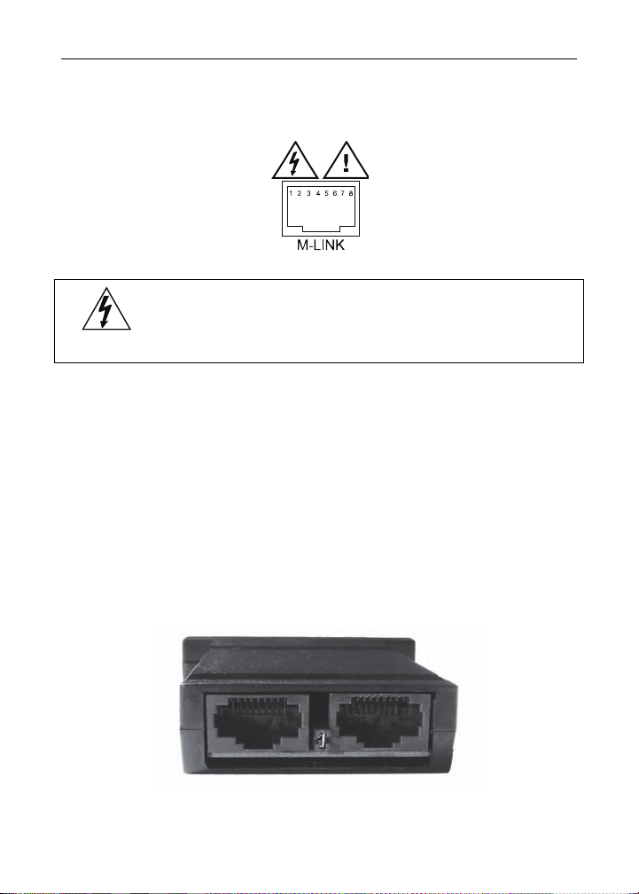
Figure 1: M-Link Connector Location on the Meter
Do not connect any equipment other than Precision
Digital’s expansion modules, cables, or meters to the
WARNING!
The two RJ45 connectors on the expansion modules are identical and
interchangeable; they are used to connect additional modules to the
system.
PDA1011 Configuration
For the PROVU to recognize the installed PDA1011 analog outputs the
module must be connected by the M-Link connector to the P
each analog output being used must be wired to and powered by a
separate DC supply than the one powering the PROVU.
PDA1044 Configuration
The jumper located between the RJ45 connectors of the PDA1044 (see
Figure 2) must be removed on the second digital I/O module in order for
the system to recognize it as module #2.
RJ45 M-LINK connector. Otherwise damage will
occur to the equipment and the meter.
ROVU and
Figure 2: Jumper Location
6
www.GlobalTestSupply.com
Page 7
®
PROV
U
Expansion Modules Instruction Manual
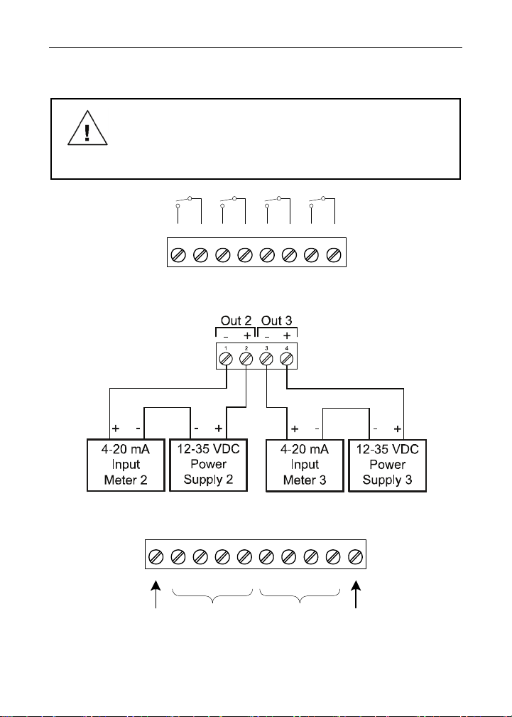
Terminal Block Connections
All connections are made to removable screw terminal connectors
located at the front of the module.
Use copper wire with 60°C or 60/75°C insulation for all
line voltage connections. Observe all safety regulations.
Electrical wiring should be performed in accordance with
Caution!
all applicable national, state, and local codes to prevent
damage to the meter and ensure personnel safety.
RLY5 RLY6 RLY7 RLY8
12
345678
NO C NO C NO C NO C
Figure 3: External Relays Module Connections
Figure 4: Dual Analog Output Module Connections
123456
+5 I1 I2 I3 I4 O1
5 VDC GND
DI 1-4 DO 1-4
78
O2 O3
910
O4 G
Figure 5: Digital I/O Module Connections
7
www.GlobalTestSupply.com
 Loading...