

Page 1
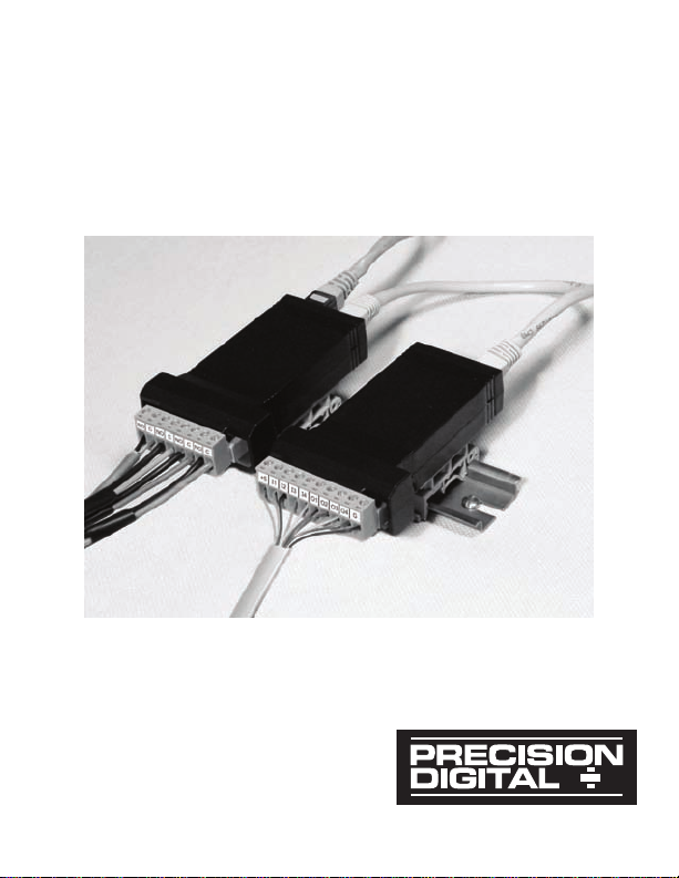
PDA1002
DIN-Rail Mounting Kit
for Two Modules
Find Q uality Pro ducts Onli ne at: sales@ GlobalTestSupp ly.com
www.GlobalTestSupply.com
Page 2
PDA1002 DIN-Rail Mounting Kit Instruction Manual
Disclaimer
The information contained in this document is subject to
change without notice. Precision Digital makes no
representations or warranties with respect to the contents
hereof, and specically disclaims any implied warranties of
merchantability or tness for a particular purpose.
© 2009-2015 Precision Digital Corporation. All rights reserved.
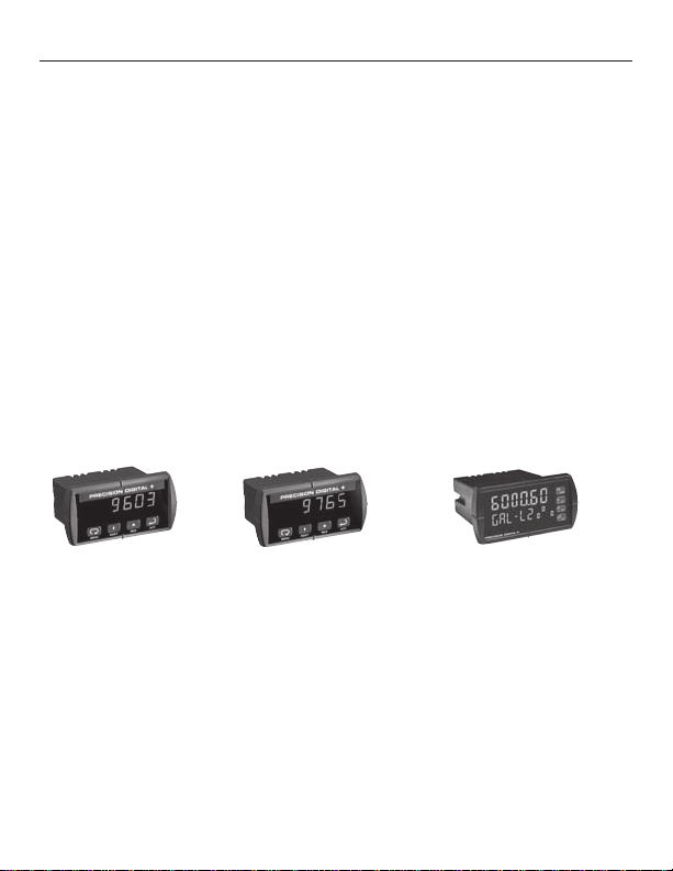
Other great products from Precision Digital!
Sabre
• Basic Features
• Display Only
• Universal Pwr Supply
• NEMA 4X
Find Q uality Pro ducts Onli ne at: sales@ GlobalTestSupp ly.com
Trident
• Congurable
• 200 mA Xmtr Supply
• 2 Relays
• Serial Communications
• Pump Alternation
• Sunlight Readable
www.GlobalTestSupply.com
2
ProVu
• Dual-Line 6-Digit Display
• Full-Featured
• 0.03% Accuracy
• Programmable
• 2/4 Relays + 4-20 mA
• Expansion Modules
• 12 VDC Input Power
• 32-Point Linearization
• -40°C Operating Temp
Page 3

PDA1002 DIN-Rail Mounting Kit Instruction Manual
Compatible Devices
The PDA1002 DIN-rail mounting kit can be used with the
following Precision Digital modules.
Model Description
PDA1004
PDA1044
PDA1232
PDA1485
ProVu 4 Relays Module
ProVu Digital I/O Module (4 In & 4 Out)
ProVu RS-232 Serial Adapter
ProVu RS-422/485 Serial Adapter
PDA7232 Trident RS-232 Adapter
PDA7422 Trident RS-422/485 Serial Adapter
PDA7485-I RS-232 to RS-422/485 Isolated Converter
PDA7485-N RS-232 to RS-422/485 Non-Isolated Converter
PDA8485-I USB to RS-422/485 Isolated Converter
PDA8485-N USB to RS-422/485 Non-Isolated Converter
Find Q uality Pro ducts Onli ne at: sales@ GlobalTestSupp ly.com
www.GlobalTestSupply.com
3
Page 4

PDA1002 DIN-Rail Mounting Kit Instruction Manual
The mounting kit includes
(1) 6" length of DIN-rail,
(4) mounting clips, and this
instruction sheet. It contains
enough parts to mount 2
modules. Please read the
instructions thoroughly before
proceeding.
INSTRuCTIONS
Locking Tab Slot
Step 1
Mounting the DIN-rail clips
to the module.
Place the expansion module
on a at surface with the bottom surface facing up. The
bottom surface can be identied as the surface closest
to the locking tab slot on the
modular connector (see picture at right).
Find Q uality Pro ducts Onli ne at: sales@ GlobalTestSupp ly.com
www.GlobalTestSupply.com
Expansion Module Example
4
Page 5
PDA1002 DIN-Rail Mounting Kit Instruction Manual
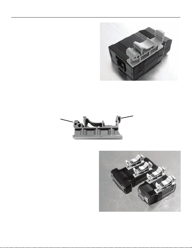
Peel the protective layer off
of the adhesive tape on the
bottom of one of the mounting clips. With the hinge end
of the clip (see below) facing
the end of the module with the
communications connector,
align the clip along the long
(side) edge of the module and
Communications Module Example
centered lengthwise within the
at surface of the module.
Hinge End
Latch End
Firmly press down on clip for
10 seconds. Repeat this procedure on opposite side. Once
clips are properly installed, the
modules with clips mounted
should look similar to one or
both of the modules pictured
to the right. While the adhesive is initially quite strong, this
strength improves signicantly
over a period of approximately
Completed Assemblies
12 hours.
Find Q uality Pro ducts Onli ne at: sales@ GlobalTestSupp ly.com
www.GlobalTestSupply.com
5
Page 6
PDA1002 DIN-Rail Mounting Kit Instruction Manual
Step 2
Mounting the DIN-rail to
your panel.
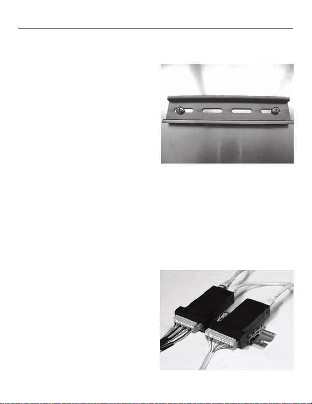
The ProVu modules are very
light (approx. 1½ oz each).
As such, the mounting hardware does not need to be very
strong. We recommend two
#10 pan head screw (shown
to the right), but only because
it best accommodates the slots in the DIN-rail. Do consider
any strain your wiring might place on the module mounting. In many cases, you may nd mounting the DIN-rail with
double-sided tape might be acceptable (not recommended
in areas of high vibration or temperatures outside the range
of 45 to 95°F). When choosing a location to mount the DINrail, keep in mind that wires will be entering both ends of the
modules (see picture shown
on the bottom right). Leave
enough space on either end of
module to allow for wire routing. Otherwise undue stress
may be placed on the module’s
connectors and mounting clips.
The DIN-rail can be mounted
on any vertical or horizontal
mounting plane, providing wiring that is properly secured.
Find Q uality Pro ducts Onli ne at: sales@ GlobalTestSupp ly.com
www.GlobalTestSupply.com
6
Page 7
PDA1002 DIN-Rail Mounting Kit Instruction Manual
Step 3
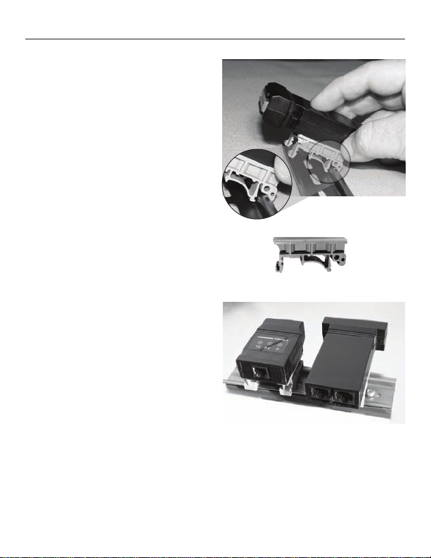
Mounting modules to DINrail.
To mount modules to DINrail, rst locate the approximate position you would like
to place the module on the
DIN-rail, then hook hinge end
of mounting clip to edge of
DIN-rail as shown to the right.
Then lower the opposite “latch
end” of the clip onto the rail.
Hinge EndLatch End
Press down on the module
until the latch end snaps in
place.
A typical installation may
look like the photo to the
right once modules are
mounted to the DIN-rail.
Step 4
After mounting the expansion module(s), please refer to the
Instruction Manual for each module for proper wiring and use
instructions.
Find Q uality Pro ducts Onli ne at: sales@ GlobalTestSupp ly.com
www.GlobalTestSupply.com
7
 Loading...