

Precision Digital PD9000-GP-8PI-10AO, PD9000-GP-4PI-E, PD9000-GP-8PI-10AO-10RY, PD9000-GP-8PI-10AO-E, PD9000-GP-8PI-8AI-10AO-5RY User manual
...Page 1

PD9000 ConsoliDator+ Multivariable Controller
Instruction Manual
• NEMA 4X Panel Mount Multi-Channel Controller
• Convenient Display, Control, & Alarm of Multiple 4-20 mA & Pulse Inputs
• Numeric & Bargraph Color Display (320 x 240 px) 5.7" (145 mm)
• Sunlight Readable Display, White Backlight
• Isolated 24 VDC Transmitter Supplies 200 mA / Analog Input; 1,600 mA Max
• 99 Channels, 32 Totalizers, 32 Timers, & 199 Modbus Slave Inputs
• 64 High & Low Alarms, Combine Multiple Alarms Into Logic AND & OR Alarms
• Simulation & Manual Control Modes for Testing Setup
• Modular Design for Input & Output Flexibility
• Up to (28) 4-20 mA Isolated Inputs or Pulse Inputs
• Up to (25) 10 Amp Form C Relays (With Eight Analog or Pulse Inputs)
• Up to (25) Isolated 4-20 mA Outputs (With Eight Analog or Pulse Inputs)
• Operating Temperature Range: -40 to 60°C (-40 to 140°F)
• Pulse, Analog, & Modbus Input Flow Rate / Total / Grand Total Capability
• 50-Point Linearization, Square Root, and Exponent for Open Channel Flow
• Round Horizontal Tank Volume Calculation; Just Enter Diameter & Length
• Multi-Pump Alternation Control or Simple On / Off Control
• Programmable Displays, Function Keys & Digital Inputs
• Math Functions: Sum, Diff, Average, Multiply, Divide, % Efficiency, & More
• Direct Modbus PV Inputs - Slave Mode
• Customize Modbus Outputs to Read Multiple Registers in One Block
• RS-485 Serial Communication with Modbus RTU
• Field Selectable Input Power: 85-264 VAC or 24 VDC
• (20) Screens with up to Eight PVs Each
• Automatic or Manual Scanning
• ConsoliDator+ Configuration Software
• NEMA 4 Field Mount Enclosure Accessory
• Light / Horn & Control Station Accessory for Remote Operation
• 3-Year Warranty
Find Quality Products Online at: [email protected]
www.GlobalTestSupply.com
Page 2

PD9000 ConsoliDator+ Multivariable Controller
Instruction Manual
Disclaimer
The information contained in this document is
subject to change without notice. Precision Digital
makes no representations or warranties with
respect to the contents hereof and specifically
disclaims any implied warranties of
merchantability or fitness for a particular purpose.
• Read complete instructions prior to installation and
operation of the controller.
• Risk of electric shock or personal injury.
• This product is not recommended for life support
applications or applications where malfunctioning
could result in personal injury or property loss.
Anyone using this product for such applications
does so at his/her own risk. Precision Digital
Corporation shall not be held liable for damages
resulting from such improper use.
WARNING
Limited Warranty
Precision Digital Corporation warrants this product
against defects in material or workmanship for the
specified period under “Specifications” from the
date of shipment from the factory. Precision
Digital’s liability under this limited warranty shall not
exceed the purchase value, repair, or replacement
of the defective unit.
FREE ConsoliDator+
Configuration Software
The easiest and quickest way to program your
ConsoliDator+ multivariable controller is to use the
FREE ConsoliDator+ configuration software.
The ConsoliDator+ configuration software is intuitive, and
most customers can get their controller programmed as
they like without even looking in the manual.
Once your controller is programmed the way you want it,
you can wire it up for your application per the instructions
in this manual and install it. If you find that you need to
adjust the programming after the controller is installed,
you can use the front panel soft keys and the instructions
in this manual to do so.
Registered Trademarks
All trademarks mentioned in this document are
the property of their respective owners.
© 2020 Precision Digital Corporation.
All rights reserved.
2
Find Quality Products Online at: [email protected]
www.GlobalTestSupply.com
Page 3

PD9000 ConsoliDator+ Multivariable Controller
Table of Contents
Introduction ......................................................................................................... 6
Ordering Information .......................................................................................... 6
Input / Output Cards ....................................................................................... 7
Setup & Calibration Services ......................................................................... 7
Accessories ..................................................................................................... 7
Specifications ................................................................................................... 10
General .......................................................................................................... 10
Totalizer ......................................................................................................... 11
Real Time Clock ............................................................................................ 11
Channel & Math Functions ........................................................................... 12
List of Engineering Units ............................................................................. 12
4-20 mA Analog Inputs ................................................................................. 13
Pulse Inputs .................................................................................................. 13
Modbus Inputs .............................................................................................. 13
Digital Inputs & Outputs ............................................................................... 14
Relays ............................................................................................................ 14
4-20 mA Transmitter Outputs ...................................................................... 15
Timers ............................................................................................................ 15
Modbus® Serial Communications................................................................ 15
Ethernet Communications ........................................................................... 15
ConsoliDator+ Software ............................................................................... 15
Safety Information ............................................................................................ 16
Installation......................................................................................................... 16
Unpacking ..................................................................................................... 16
Panel Mounting ............................................................................................. 16
Mounting Dimensions .................................................................................. 17
ConsoliDator+ Configuration Software Installation ................................... 18
ConsoliDator+ Software ............................................................................... 19
Connections ...................................................................................................... 20
Power Connections ..................................................................................... 21
Analog Output Connections ......................................................................... 22
Digital Output Connections .......................................................................... 22
Connections to Power Gas Detector ........................................................... 23
Serial Communication Connections ............................................................ 24
External Keypad Connections ..................................................................... 24
Navigating and Editing ..................................................................................... 25
Soft-Keys and Buttons ................................................................................. 25
Setup and Programming .................................................................................. 26
Overview ........................................................................................................ 26
Setup Menu ....................................................................................................... 27
Channel Parameters ..................................................................................... 28
Data Entry Keypad ........................................................................................ 29
Setup Channels ............................................................................................. 30
Create New Channel ................................................................................... 31
Bargraph, Background & Text Colors .......................................................... 32
Live Calibration ............................................................................................ 33
Edit Channel ................................................................................................ 33
Delete Channel ............................................................................................ 33
2-Point Linear Scaling ................................................................................. 34
Square Root Scaling ................................................................................... 34
Scale Exponent ........................................................................................... 35
Round Horizontal Tank ................................................................................ 35
Open Channel Flow Application .................................................................. 36
Setup Math Functions ................................................................................. 37
Setup Totalizers .......................................................................................... 38
Setup Total with Pulse Input Source ........................................................... 38
Instruction Manual
3
Find Quality Products Online at: [email protected]
www.GlobalTestSupply.com
Page 4

PD9000 ConsoliDator+ Multivariable Controller
Setup Timers ............................................................................................... 39
Setup Alarms ............................................................................................... 40
Logic OR Alarm ........................................................................................... 41
Logic AND Alarm ......................................................................................... 41
Logic NOR & NAND Alarms ........................................................................ 41
Setup Inputs .................................................................................................. 42
Setup 4-20 mA Inputs .................................................................................. 42
Setup Pulse Inputs ...................................................................................... 43
Setup Digital Inputs ..................................................................................... 43
Setup Modbus Inputs .................................................................................. 44
Setup All Outputs.......................................................................................... 45
Setup 4-20 mA Outputs ............................................................................... 45
Setup Relay Output ..................................................................................... 46
Setup Digital Output .................................................................................... 48
Setup Modbus Output ................................................................................. 48
Setup Screens ............................................................................................... 49
Screens Settings ......................................................................................... 49
Setup System ................................................................................................ 51
Setup Display .............................................................................................. 51
Setup Colors ................................................................................................ 51
Display Settings ........................................................................................... 51
General Settings .......................................................................................... 52
Set Password .............................................................................................. 52
Password Protected Controller .................................................................... 52
Remove Password Protection ..................................................................... 52
System Date & Time ................................................................................... 53
Modbus Settings & Passcode Protection .................................................... 53
System Build ............................................................................................... 53
Ethernet Settings ......................................................................................... 53
Ethernet Port Setup - Full ................................................................................ 54
Test Ethernet Communication ..................................................................... 56
Custom Units ............................................................................................... 57
View Menu ..................................................................................................... 58
View Channel Details .................................................................................. 58
View Totals .................................................................................................. 60
Totals Generated by Non-Rate Inputs ......................................................... 61
View Timers ................................................................................................. 62
View Alarms ................................................................................................ 63
View Inputs .................................................................................................. 64
View Outputs ............................................................................................... 65
View Alert Messages ................................................................................... 66
View Digital Outputs .................................................................................... 67
View Modbus Outputs ................................................................................. 67
View Screens .............................................................................................. 68
Operation........................................................................................................... 69
Viewing Screens ........................................................................................... 69
Individual Channel View .............................................................................. 69
Low & High Alarm Indication ....................................................................... 69
Multicolor Bargraph Indication ..................................................................... 70
Modbus® RTU Serial Communication ............................................................. 71
Modbus Register Tables .............................................................................. 71
PV’s Register Numbers & Addresses ......................................................... 73
Modbus Write Protection ............................................................................. 74
Relay Control Using Modbus ....................................................................... 78
Setup Example #1 ....................................................................................... 78
Setup Example #2 ....................................................................................... 78
Troubleshooting Tips ....................................................................................... 79
Instruction Manual
4
Find Quality Products Online at: [email protected]
www.GlobalTestSupply.com
Page 5

PD9000 ConsoliDator+ Multivariable Controller
Instruction Manual
Table of Figures
Figure 1. Front Panel Mount Dimensions ................................................................................................................ 16
Figure 2. Panel Cutout Dimensions .......................................................................................................................... 16
Figure 3. Panel Mount Installation ............................................................................................................................ 17
Figure 4. Panel Mount Overall Dimension ............................................................................................................... 17
Figure 5. Connection Terminals for a PD9000-GP-4PI-8AI-10AO-10RY ................................................................. 20
Figure 6. Power Connections .................................................................................................................................... 21
Figure 7. Transmitters Powered by ConsoliDator+ Isolated 24 VDC Power Supply ............................................ 21
Figure 8. Transmitter Powered by Ext. Supply or Self-Powered ........................................................................... 21
Figure 9. 3-Wire Transmitters Powered Externally .................................................................................................. 21
Figure 10. Flow Meter Pulse Input Connections ...................................................................................................... 22
Figure 11. Digital Input from Switch Closure and Live Signal ............................................................................... 22
Figure 12. Active 4-20 mA Output Powered by Controller ...................................................................................... 22
Figure 13. Passive 4-20 mA Output Powered by External Supply ......................................................................... 22
Figure 14. Digital Outputs Driving 5 V Solid State Relay ........................................................................................ 22
Figure 15. Two Supplies in Parallel Powering 3-Wire Transmitter ......................................................................... 23
Figure 16. Powering 4-Wire Gas Detector & Isolated 4-20 mA Output .................................................................. 23
Figure 17. Relay Connections ................................................................................................................................... 24
Figure 18. AC and DC Internal Inductive Loads Protection
Figure 19. Low Voltage DC Loads Protection .......................................................................................................... 24
Figure 20. Serial Connections ................................................................................................................................... 24
Figure 21. External Keypad Connections ................................................................................................................ 24
Figure 22. Linear Response Graph ........................................................................................................................... 34
Figure 23. Square Root Response Graph ................................................................................................................ 34
Figure 24. Exponent Response Graph ..................................................................................................................... 35
Figure 25. Round Horizontal Tank Volume Graph ................................................................................................... 35
Figure 26. Total Relay Sampling Operation ............................................................................................................. 36
......................................................................................... 24
5
Find Quality Products Online at: [email protected]
www.GlobalTestSupply.com
Page 6

PD9000 ConsoliDator+ Multivariable Controller
Model
Pulse Inputs
4-20 mA Inputs
4-20 mA Outputs
Relays
PD9000-GP-4AI
0 4 0
0
PD9000-GP-4AI-10RY
0 4 0
10
PD9000-GP-4AI-5AO-10RY
0 4 5
10
PD9000-GP-4AI-20RY
0 4 0
20
PD9000-GP-4AI-5AO-20RY
0 4 5
20
PD9000-GP-8AI
0 8 0
0
PD9000-GP-8AI-10RY
0 8 0
10
PD9000-GP-8AI-10AO-10RY
0 8 10
10
PD9000-GP-8AI-20RY
0 8 0
20
PD9000-GP-8AI-25RY
0 8 0
25
PD9000-GP-12AI
0
12
0
0
PD9000-GP-12AI-20RY
0
12
0
20
PD9000-GP-12AI-10AO-10RY
0
12
10
10
PD9000-GP-16AI
0
16
0
0
PD9000-GP-16AI-15RY
0
16
0
15
PD9000-GP-16AI-15AO
0
16
15
0
PD9000-GP-20AI
0
20
0
0
PD9000-GP-20AI-10RY
0
20
0
10
PD9000-GP-20AI-10AO
0
20
10
0
PD9000-GP-24AI
0
24
0
0
PD9000-GP-24AI-5RY
0
24
0
5
PD9000-GP-24AI-5AO
0
24
5
0
PD9000-GP-28AI
0
28
0
0
PD9000-GP-4PI
4 0 0
0
PD9000-GP-4PI-5AO
4 0 5
0
PD9000-GP-4PI-5AO-10RY
4 0 5
10
PD9000-GP-4PI-4AI-5AO
4 4 5
0
PD9000-GP-4PI-4AI-5AO-10R
4 4 5
10
PD9000-GP-4PI-8AI-10AO-10RY
4 8 10
10
PD9000-GP-8PI
8 0 0
0
PD9000-GP-8PI-10AO
8 0 10
0
PD9000-GP-8PI-10AO-10RY
8 0 10
10
PD9000-GP-8PI-8AI-10AO-5RY
8 8 10
5
Other models are available upon request.
Introduction
The ConsoliDator+ is a multi-channel controller that is both
easy to use and satisfies a wide variety of process display,
alarm, and control applications. It accepts 4-20 mA inputs,
flow meter pulse inputs, digital inputs, and Modbus RTU
inputs and displays them both in numeric and bargraph
format on a large, 5.7" color display. It can be equipped with
multiple relays with user-definable actions, 4-20 mA outputs,
digital outputs, Modbus RTU, and Ethernet Modbus TCP/IP
protocol communication capabilities. Additionally, the
controller is equipped with up to 32 timers that can be used
to control many processes or events.
The ConsoliDator+ takes full advantage of its color display
by allowing the user to customize screen colors for
bargraphs, alarm conditions, and input channels.
All this functionality is easily programmed using free
software or via the front panel pushbuttons. Choose the
model that best suits your application, from monitoring
only to fully loaded controllers with an extensive
combination of inputs, outputs and communication
protocols. The standard product offering is listed in the
ordering guide and other models are available for special
order.
Ordering Information
General Purpose Panel-Mount Models
Instruction Manual
G = General Purpose
P = Panel-Mount
AI = Analog Input
PI = Pulse Input
Find Quality Products Online at: [email protected]
www.GlobalTestSupply.com
AO = Analog Output
RY = Relay
E = Ethernet (Add “–E” at the end of the model number)
Example: PD9000-GP-4PI-8AI-10AO-10RY-E
6
Page 7
PD9000 ConsoliDator+ Multivariable Controller
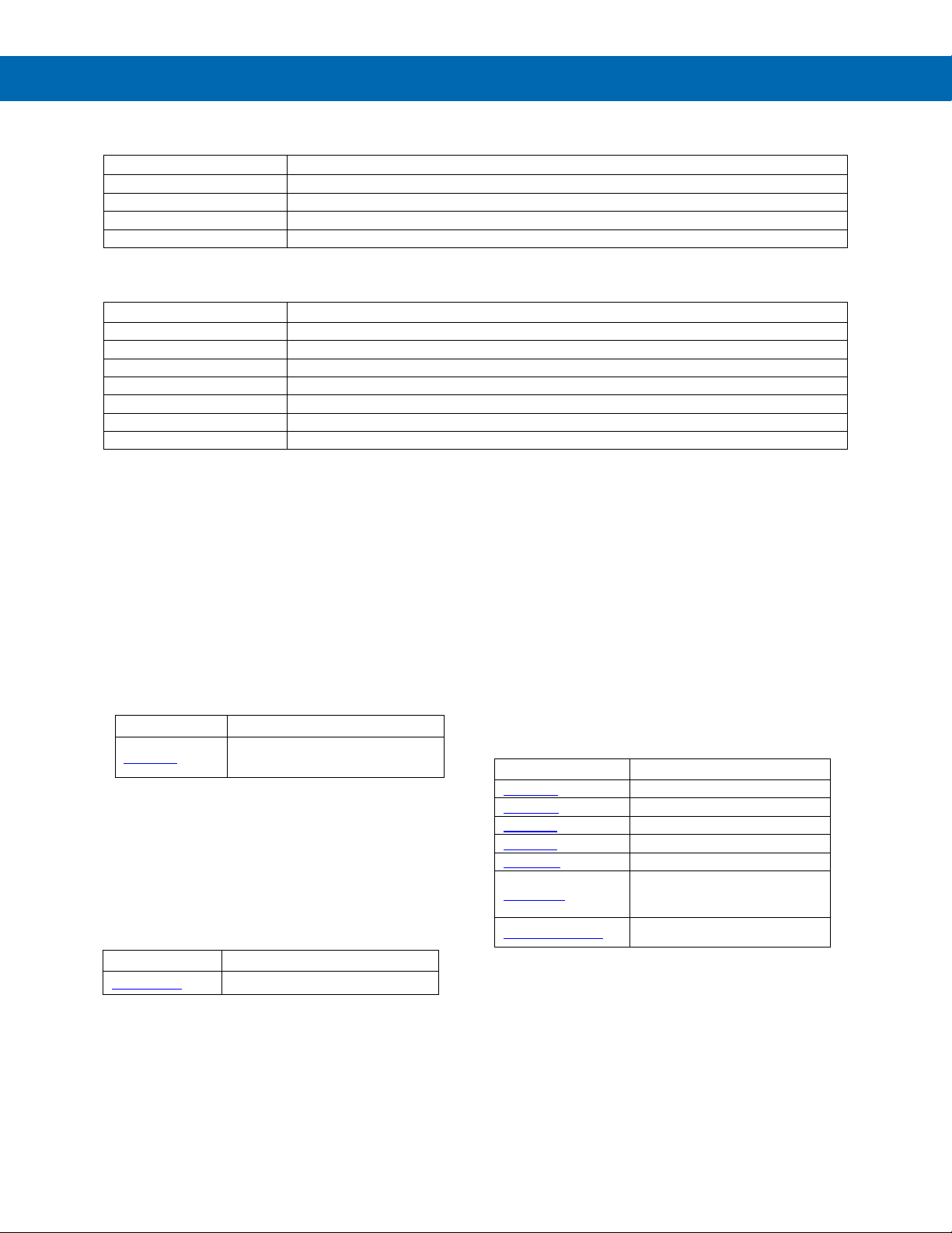
Model
Description
PDA9000-C4AI
(4) Isolated 4-20 mA Inputs Card for ConsoliDator+
PDA9000-C4PI
(4) Pulse Inputs Card for ConsoliDator+
PDA9000-C5AO
(5) Isolated 4-20 mA Outputs Card for ConsoliDator+
PDA9000-C5RY
(5) Relays Card for ConsoliDator+
Part Number
Description
PDN-CALCON+12
ConsoliDator+ Calibration and Certificate for up to 12 Inputs and Outputs
PDN-CALCON+24
ConsoliDator+ Calibration and Certificate for up to 24 Inputs and Outputs
PDN-CALCON+36
ConsoliDator+ Calibration and Certificate for up to 36 Inputs and Outputs
PDN-CALCON+12-DATA
ConsoliDator+ Calibration and Certificate with data for up to 12 Inputs and Outputs
PDN-CALCON+24-DATA
ConsoliDator+ Calibration and Certificate with data for up to 24 Inputs and Outputs
PDN-CALCON+36-DATA
ConsoliDator+ Calibration and Certificate with data for up to 36 Inputs and Outputs
PDN-CSETCON+
Custom Setup for ConsoliDator+
PDA-LHR
Red Light / Horn
PDA-LHG
Green Light / Horn
PDA-LHY
Yellow Light / Horn
PDA-LHB
Blue Light / Horn
PDA-LHW
White Light / Horn
Light
Light / Horn with Red, Yellow,
Green Light Layers
Input / Output Cards
Setup & Calibration Services
Accessories
NEMA 4 Steel Enclosure
Instruction Manual
Light / Horn Accessories
Model Description
PDA2909
NEMA 4 Steel Enclosure for One
ConsoliDator+
PDA9000SH Sun Hood
Model Description
PDA9000SH ConsliDator+ Sun Hood
Model Description
Light / Horn with User Choice of
PDA-LH5C
PDA-LH3LC-RYG
Red, Green, Yellow, Blue or White
7
Find Quality Products Online at: [email protected]
www.GlobalTestSupply.com
Page 8
PD9000 ConsoliDator+ Multivariable Controller
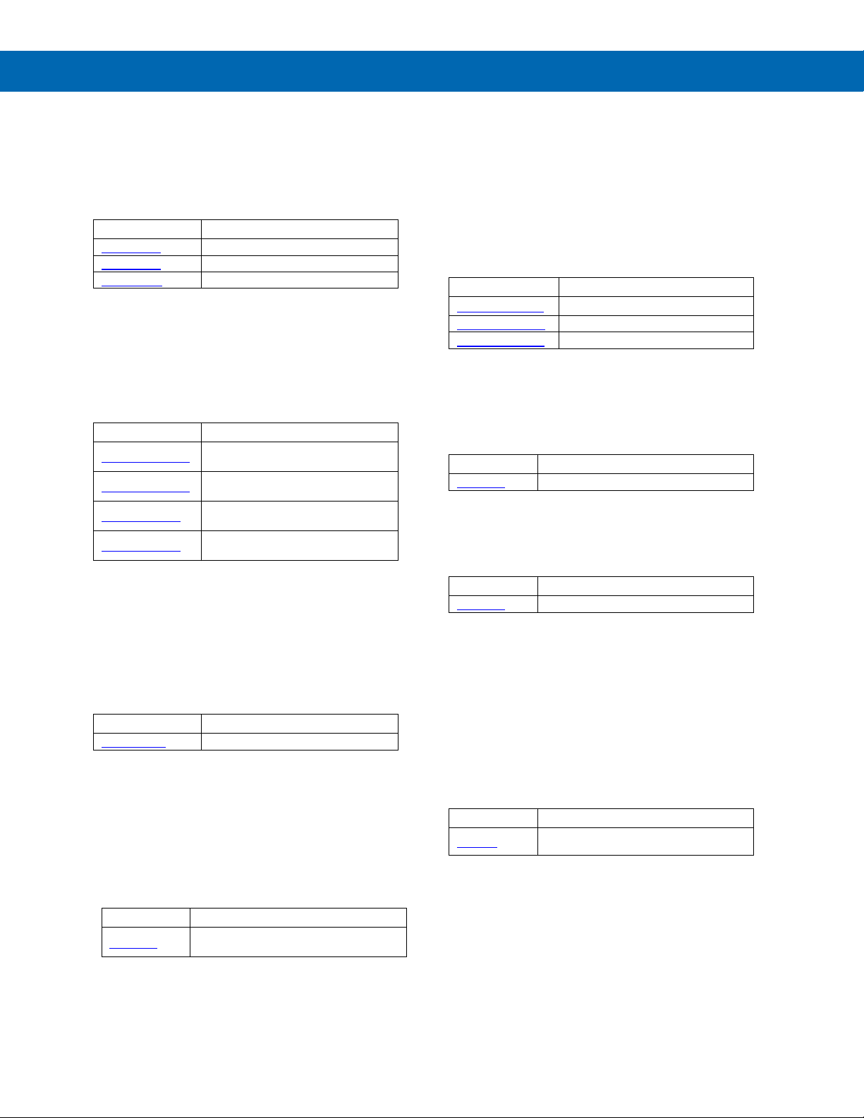
PDA2360-E
Emergency Stop Button
PDA2361-A
1 Black Ack Button
PDA2361-Q
1 Black Silence Button
Signal Isolator with One 4-20 mA
Input and One 4-20 mA Output
Signal Splitter with One 4-20 mA
Input and Two 4-20 mA Outputs
Signal Conditioner with One 0-10
VDC Input and One 4-20 mA Output
Signal Conditioner with One 4-20
mA Input and One 0-10 VDC Output
Model
Description
PDA1024-01
24 VDC Power Supply for DIN Rail
Model
Description
Input: 30/60/120 AAC; Output 4-20 mA
Model
Description
PDA-BUTTON1G
NEMA 4X Green Reset Button
PDA-BUTTON1R
NEMA 4X Red Reset Button
Model
Description
PDA1000
Panel Mount Buzzer and Light
PDX6901
Snubber 0.01μF/470Ω Flexible Leads
4-20 mA or 0-10 VDC,
Low-Cost Signal Generator
PDA2360 Control Stations
Model Description
Instruction Manual
PDA-BUTTON Momentary Pushbutton
Signal Splitter & Conditioner Accessories
Model Description
PD659-1MA-1MA
PD659-1MA-2MA
PD659-1V-1MA
PD659-1MA-1V
PDA1024-01 Power Supply
PDA-BUTTON1B NEMA 4X Black Reset Button
Panel Mount Buzzer and Light
Snubber 0.01μF/470Ω Flexible Leads
Model Description
Low-Cost Signal Generator
Split Core AC Current Transducer
Model Description
PD9502
PDA6420
Split Core AC Current Transducer.
Find Quality Products Online at: [email protected]
www.GlobalTestSupply.com
8
Page 9
PD9000 ConsoliDator+ Multivariable Controller
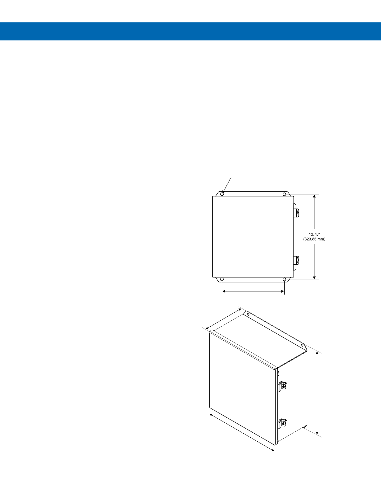
10.0" (254 mm)
(4) Mounting H oles
13.5"
(343 mm)
6.2"
(157 mm)
12.0"
(305 mm)
PDA2909 NEMA 4 Steel Enclosure
for One ConsoliDator+
The PDA2909 steel NEMA 4 enclosure provides a
convenient way to mount the PD9000 ConsoliDator+
to walls and other vertical structures. This enclosure
comes pre-cut with one cutout to mount the PD9000
in. The ConsoliDator+ is mounted in the door of the
enclosure thus allowing for programming and
operation of the device. No additional mounting
hardware other than screws to mount to the wall is
needed. The door is hinged and secured with latches.
Note: The enclosure and ConsoliDator+ are ordered
and packaged separately
.
Instruction Manual
Features
● House One ConsoliDator+ Multi-Variable Controller
● 14-Gauge Steel
● Comes Pre-Cut with One Cutout
● NEMA 4, 12 and 13
● Cover Secured with Screwed Latches
● Hinged Door
● ConsoliDator+ Mounted in Cover
● Mounting Holes Integral to Enclosure
● UL Listed, CSA Certified
Wall Mounting Dimensions:
The PDA2909 enclosure includes integral mounting
flanges at the top and bottom of the enclosure that can
be used to mount the enclosures to a wall.
PDA2909 with ConsoliDator+ Installed
PDA2909 Opened with ConsoliDator+ Installed
PDA2909 Overall Dimensions:
ls
Find Quality Products Online at: [email protected]
www.GlobalTestSupply.com
9
Page 10

PD9000 ConsoliDator+ Multivariable Controller
Color; QVGA (320x240 px),
Feet & Inches Format: 99,999' 11.9"
Screen
Enable/disable: Channels, totals, timers
Screen: Select to show bargraph or not.
Color Selection
65 colors selection
and text for normal and alarm conditions.
Decimal Point
0 to 15 decimal places, user selectable
Engineering
User selectable units or custom units
Time, Distance, Volume, Pressure, Weight,
See page 12 for list of units.
Units
Units’ conversion is supported for
base units (e.g. Gallons/min)
Display
Update Rate
User selectable: 0.1 to 0.5 sec
(10 updates/sec to 2 updates/sec)
Programming
Method
Front panel buttons, external buttons, or
ConsoliDator+ Software
Number Of
Up to 64 high or low
Note: Alarms are independent from relays.
Alarm
Single Source: One input
trigger the AND alarm
Alarm Ack
Automatic only (Non-latching)
(Latching with Clear)
Alarm
1. Bargraph, panel, and text can be set
3. Assign external relay to drive a horn
Internal Buzzer
60 dBA @ 24 inches (61 cm)
Associated with alarm Horn setting
External Horn
Assign any relay to the Horn function to
condition is detected.
Live Channel
Calibration
Live calibration of channels is independent
of the input calibration used for scaling.
Input &
Max Number of I/O Cards: 7
Relays: 5/card
Number of
Up to 20 screens with 1 to 8 PVs or items
F1-F4 keys are assigned per screen
Function
User programmable (See defaults below)
F4 = Ack
Number of
Up to 99 channels
Output, Digital Output, or Modbus Output
Password
Programmable password restricts
are not protected.
Simulation
Inputs, channels, totals, timers, and alarms
simulated items.
Manual Control
Analog outputs and relays can be
power down. Alert! message is provided for
is necessary to turn relays off and
e,
configure the relays to Always Off.
Non-Volatile
Memory
Settings stored for a minimum of
Power
Three-terminal connector (L, N, GND)
DC: 24 VDC ±10%, 60 W max
Backup
If AC and DC power are connected, the
otherwise the system runs on DC power.
Fuse
Unit is protected internally with auto-
Specifications
Except where noted all specifications apply to operation at 25°C (77°F)
General
Instruction Manual
Display
Bargraph
Units
Conversion
Alarms
5.7" (145 mm) diagonally, white backlight
Bargraph: Twenty divisions
Numerical: Up to 15 digits
(±999,999,999,999,999)
Bargraph scale: 0 – 100%, independent of
channel scale. Twenty divisions: 5% each.
Customize bargraph, panel background,
Temperature, Current, Voltage, Percent,
Amps, Volts, Counts, Logic, and Custom,
Any unit/unit of time or other units.
channels, totals, timers, and any function
using those parameters.
Channel scaling must be in the intended
Automatic (non-latching) or latching
On & Off time delays
May be assigned to one or more relays.
Output
Cards
Screens
Keys
Channels
Mode
Analog Inputs: 4/card
Pulse Inputs: 4/card
Analog Outputs: 5/card
per screen
Enable or disable screen title, channel #,
and bargraph
Automatic or manual scanning
Scan time: 1 to >1000 sec, independent for
each screen
F1 = Previous
F2 = Next
F3 = Scan/Stop
Input Source: 4-20 mA, Pulse, Digital,
Modbus, another Channel, Total, Timer,
Alarm, Date & Time, mA Output, Relay
modification of programmed settings.
View and Setup menus are password
protected, function keys and digital inputs
can be simulated from the View menu or
from a function key.
Simulation mode is not saved on power
down. Alert! message is provided for
controlled manually from the View menu
Types
& Reset
Indication
Find Quality Products Online at: [email protected]
(Sold Separately)
Multi-Source: Two or more inputs
Interval: Enter time interval and On Time
Day & Time: Select day of the week & time
Alarm OR: Any active input alarm triggers
Alarm AND: All alarms must be active to
Automatic and manual
Manual only (Latching)
Manual with Ack only after alarm is cleared
2. Enable internal buzzer
Enable/disable in System – General menu.
activate an external horn when alarm
the OR alarm
up to change color on alarm
www.GlobalTestSupply.com
User Selectable
Based on
Wiring
Power Supply
10
or from a function key.
Manual control mode is not saved on
outputs in manual control.
Note: If it
maintain the condition through power cycl
10 years.
AC: 80-264 VAC, 47 to 63 Hz, 60 W max
DC: 113-370 VDC, 60 W max (L, N)
Two-terminal connector (G, 24V)
24 VDC can be used as backup power in
case of AC power failure.
Note: DC supply must be 24 V or less;
resettable fuse
AC: 1.25 A max
DC: 3.7 A max
Page 11

PD9000 ConsoliDator+ Multivariable Controller
External
Recommended external fuse slow-blow
24 VDC: 4 A
Isolation &
1500 V
output, analog
Environmental
Operating temperature range: -40 to 60°C
increase display refresh setting.
Internal Fan
Automatic temperature-controlled fan turns
temperature rises to 60°C.
Internal Heater
Automatic temperature-controlled heater
delivers its maximum power.
Connections
Removable screw terminal blocks
cable included.
Tightening
Screw terminal connectors:
Digital I/O terminals: 2.5 lb-in (0.28 Nm)
Enclosure
Enclosure Body: Thermoplastic Polyester,
Front Panel Keys: Silicone rubber
Mounting
Panel-mounting frame and twelve screws
Overall
10.85" x 10.85" x 4.87"
(H x W x D)
Weight
Ex: PD9000-XY-4PI-8AI-10AO-10RY
7.4 lb (3.4 kg) approx.
Warranty
Number of
Up to 32 totalizers
15 digits with comma separator
Totalizer Inputs
Calculates total based on selected rate
power is lost.
Maximum Total
18 digits
999,999,999,999,999,999
Rate Channel
Input
4-20 mA input, Pulse input, Modbus input
Rate & Total
Decimal Point
Independent and user selectable from 0 to
15 places
Totalizer Reset
Via front panel keys or digital inputs
Non-Resettable
Total may be setup to be non-resettable to
changed in the Setup Totals menu.
Total Units
Input: Rate channel
(e.g. Gallons to MGal: Factor = 0.000001)
Pulse Input
K-Factor = pulses/units of measure
Decimals: 0 to 15
Count
Down
Total may be setup to count down from a
predetermined value entered by the user
Preset
Enter the preset value to count up or down
; to
reset to zero uncheck the Preset box.
Roll-Over
Enter the value for total to roll-over to 0
Total goes to 0 after 1 million
Negative Total
Allow total value to count below 0 for
bi-directional flow based on rate channel
Total Bargraph
Bargraph may be scaled to represent the
expected maximum total
Function Keys
Screen Setup: Assign F1-F4 to Reset
Remove From total
Date
Format
Month, day, year (e.g. July 16, 2020)
Time
Format
24 hour; 00: Midnight
hh:mm:ss
Battery
3 V, P/N: CR2032 included
Display
Date & Time
Displayed on the top line of Setup and
View menus, including day of the week.
Screens
Date & Time can be added to any screen.
Channels
Date & Time can be the input to a channel.
Display Format: yyyy/mm/dd hh:mm:ss
Instruction Manual
Fuse
Grounding
120 VAC: 2.0 A
240 VAC: 1.0 A
Analog inputs/outputs-to-power line
500 V
Analog input-to-input, input-tooutput-to-output
All analog inputs and analog outputs are
isolated from each other.
Note: DC Power is not isolated. DC- is
connected to Earth Ground. Digital I/O,
USB, and Ethernet are grounded.
(-40 to 140°F)
Storage temperature range:
-40 to 60°C (-40 to 140°F)
Relative humidity: 0 to 90% noncondensing
*All functions operate down to
-40°C (-40°F.) LCD response is slower,
on if the inside temperature reaches 50°C
and increases the speed as the
located behind the LCD turns on at 0°C,
delivering the minimum power. If the
temperature drops below -10°C, the heater
Totalizer
Totalizers
Total
Conversion
K-Factor
channel, pulse input, digital input, or
triggered event for non-rate channels.
Total is stored in non-volatile memory if
prevent unintentional reset. This can be
Total units may be different than rate units.
Use the custom units to convert to any unit
Calculates total directly from pulse input,
digital input, or Modbus input.
Create rate channel by entering K-Fac
units and time base in sec, min, hr, or day.
tor,
Inputs/Outputs: 12 to 24 AWG wire
Digital I/O: 16 to 30 AWG
RS-485: 12 to 24 AWG wire
RJ45 Ethernet connection.
USB ports: Micro-USB (Device),
Torque
Dimensions
Find Quality Products Online at: [email protected]
5 lb-in (0.56 Nm)
Color: Gray
Display Window: Clear Polycarbonate, GE
LEXAN HP12W
(provided)
Cutout: 10.0" x 10.0" ±0.05"
(254 mm x 254 mm ±1.3 mm) (H x W)
Panel thickness: 0.07" – 0.35"
(1.8 mm – 8.9 mm)
Clearance behind panel: 6" (152 mm)
(276 mm x 276 mm x 124 mm)
3 years parts and labor.
www.GlobalTestSupply.com
Value
Real Time Clock
11
Reset total sets total to the preset value
Example: Roll-Over = 1,000,000
Total, Enter Total, Add To, or
Page 12

Scale Functions
K-Factor
Converts number of
other units
channel
Scale Linear 2-Pt
Scale a channel
Scale Multi-Point
Multi-point scaling of
a channel
Scale
Apply square root to
from two channels
Scale Exponent
Apply exponent for
calculation
Round Horizontal
Calculate volume in
with flat ends
Units Conversion
Convert base units to
any units
Math Functions
Constant
Assign fixed value
Summation
Add two or more
channels
Difference
Subtract any two
channels
Abs Difference
Difference always
positive
Absolute Value
Convert channel
value to positive
Average
Find the average of
channels
Weighted Average
Assign % weight to
two or more channels
Multiply
Multiply two channels
Divide
Divide two channels
% Efficiency
Calculate input to
((A-B)/A)*100%
Additional
Greatest
Greatest value in a
group of channels
Least
Smallest value in a
group of channels
Measure
Tare
Calculate net value
key
Maximum
Maximum value
process
Minimum
Minimum value
process
Percent
% bargraph of any:
or mA output
Duration
Keep track of time a
alarm active)
Rate of Change
Calculates how fast a
/sec, /min, /hr, /day
Filter
Window Average
Enter time to
calculate the average
IIR (First Order)
Infinite Impulse
Response (slow)
Cutoff
PV = 0 below cutoff
Flip Side: 0 above (-)
lower limits.
Control
Sampler
Trigger relay sample
by 1,000 Gallons)
On-Off Control
Set on & off control
value
Select A or B
Switch between 2
inputs
Schedule
Daily or weekly event
Cycle Count
Number of relay
cycles since reset
Runtime
Relay runtime (ON)
hh:mm:ss
Time Since
Time since a Modbus
register
Time Since
Time since a Modbus
register
PD9000 ConsoliDator+ Multivariable Controller
Channel & Math Functions
pulses to volume or
Scale Factor Apply multiplier to a
Square Root
a channel –
Differential Pressure
Instruction Manual
Compare
Functions
when Tare function is
applied via function
reached by the
weirs and flumes
open channel flow
Tank
round horizontal tank
output efficiency
List of Engineering Units
None: No units
Time: seconds, minutes, hours, days & /sec, /min, /hr, /day
Distance (Height): cm, m, Inch, Feet, Ft-In, Yard, km, miles, custom
Volume: Gallons, GAL, L, IGAL, M3, BBL, BUSH, cuYD, cuFt, cuIn,
Pressure: psi, Pa, bar, hPa, kPa, MPa, GPa, inH2O, cmH2O, inHg,
Weight: grams, Oz, Lb, lb, g, kg, onces, tons, tonnes, custom
Temperature: C, F, K, Ra
Percent: %, PCT, Percent, custom
Amps: mA, Amps, custom
Volts: V, mV, Volts, custom
Counts: Pulses, Cycles, Counts, custom
Logic: ON, OFF, OPEN, CLOSED, YES, NO, START, RUNNING,
Custom: Enter unit’s name, type, base unit, and factor.
LiBBL, BBBL, HECtL, quarts, pints, fl oz, mL, DT, M/T,
custom
mmHg, atm, kg/cm2, kg/m2, mbar, Mbar, Torr, mTorr,
custom
STOP, STOPPED, PUMP ON, PUMP OFF, OK, OKAY,
ERROR, WARNING, custom
reached by the
(Bargraph)
Limits Sets PV’s upper &
Relays
Modbus
Read
Write
4-20 mA input,
channel, total, timer,
condition has been
present (e.g. high
process is changing
and select sampling
time (e.g. Turn relay
on for 30 sec every
time total increases
based on process
master device read a
master wrote to a
Find Quality Products Online at: [email protected]
www.GlobalTestSupply.com
12
Page 13

PD9000 ConsoliDator+ Multivariable Controller
Number of
(28) Analog inputs max, no other I/O
Typical Input
4-20 mA
Input Range
0-24 mA
Accuracy
±0.03% of full scale ±1 count
4-20 mA
Up to six full digits
rate to get a more stable reading.
Transmitter
Isolated 24 VDC @ 200 mA/input
Available on AC or DC powered units
Temperature
Drift
Better than:
20 ppm/°C from -40 to 60°C ambient
Filter
Window: 0.5, 1, 2, 4, 8 sec,
caused by high frequency noise
Filter
0 to 100 % of full scale
greater than bypass value
Channel
Linear 2-Point,
None (mA Input Reading)
Channel
Calibration
Each channel may be calibrated using
calibrator.
Input Protection
Each 4-20 mA input is protected by an
fault condition is removed.
Input Impedance
fuse
Hart
The controller does not interfere with
secondary HART variables.
Isolation
1500 V: Input-to-power line
isolated from each other.
Normal Mode
Rejection
Common Mode
Rejection
90 dB at 50/60 Hz
Number Of
(28) Pulse inputs max, no other I/O
Input Type
Active Square Wave, NPN, PNP, Reed
100 mV (High)
Signal Level
Active Square Wave: 0 to 30 V max
(Magnetic Pickup)
Input
Active, NPN, Reed: 10 kΩ pull-up to 5 V
(100 mV sensitivity)
Isolation
Pulse inputs are not isolated, (S-) terminal
is connected to system GND
Input
Protection
±36 V, non-isolated
Frequency
20 Vp-p – 50 kHz
Minimum
Frequency
250 µHz with High Gate = 4,000 sec
Low Gate
1 to 99 sec
High Gate
2 to 4,000 sec
(Must be higher than low gate)
Accuracy
±1 count for K-Factor > 1 or 30 ppm
K-Factor
Programmable pulses/unit of measure
with up to 15 decimal resolution
Scale
Pulse Input
Linear 2-Point
Multi-Point Scaling: 2 to 50 points
Live Calibration
Pulse input channel may be calibrated
using live calibration signal from a sensor.
Inputs
Scale Mb Input
way 4-20 mA inputs are used.
Data Type
Bit-Logic
Decimal Point
User selectable
Comm Break &
Specify what value to hold on comm.
before reporting a break condition.
Input
Specify what should happen when new
add value to total).
Instruction Manual
4-20 mA Analog Inputs
Inputs
Display
Value
Power Supply
Bypass
Input Scale
Function
(4) Analog inputs/card
(Recommended) ±999,999
More digits may be used, but the
stability will be affected. Increase the
filter value and lower the display update
Max current: 1,600 mA (All inputs)
(8) Analog Input @ 200 mA max
(28) Analog Input @ 20 mA max
IIR: 16, 32 sec
Glitch Filter: Discards a single sample
Filter is ignored, if the signal change is
Multi-Point (up to 50 points)
Square Root
Programmable Exponent
Scale Factor
Round Horizontal Tank (Volume)
Pulse Inputs
Inputs
Impedance
Response &
Signal Level
(4) Pulse inputs/card
Switch, Coil (Magnetic Pickup)
Normal threshold: 1.2 V (0.8 to 3.0 V)
High threshold: 2.5 V (2.0 V to 6.0 V)
Coil threshold: 20 mV (Low) or
Coil: 20 mVp-p to 30 Vp-p
PNP: 10 kΩ pull-down to (S-)
Coil: >2 kΩ (20 mV sensitivity), >10 kΩ
Active Square Wave 5 V: 0 to 100 kHz
Coil (Magnetic Pickup): 0 to 50 kHz
Frequency – Signal level (Coil: 20 mV)
20 mVp-p – 100 Hz
100 mVp-p – 10 kHz
Frequency – Signal level (Coil: 100 mV)
100 mVp-p – 90 Hz
500 mVp-p – 5 kHz
Typical: 0 to 5 V
Input Live
Transparency
Find Quality Products Online at: [email protected]
live calibration signal from a sensor or a
auto-resettable fuse, 30 VDC max.
The fuse resets automatically after the
125 Ω typical, including auto-resettable
existing HART communications; it
displays the 4-20 mA primary variable
and it allows the HART communications
to pass through without interruption. The
controller is not affected if a HART
communicator is connected to the loop.
The controller does not display
500 V: Input-to-input, input-to-output
All analog inputs and analog outputs are
100 dB at 50/60 Hz
www.GlobalTestSupply.com
Modbus Inputs
Number of
Timeout
Action
13
199 Modbus RTU
Modbus input may be used as the input
for creating channels and totals, the same
Signed/Unsigned: 16 (Short), 32 (Long),
64 (Long-Long)
Float 32
Float 64 (Double)
break and how long to wait for new data
data is written to the input register (e.g.
Page 14

PD9000 ConsoliDator+ Multivariable Controller
Digital
inputs
Digital Input
Normally open switch: External excitation not
Logic level: 0 to 30 V
Assignment &
Active Low or Active High
channels, totals, and alarms.
Digital
4 Outputs
Max frequency: 5 Hz
Digital Output
channel, alarm, horn, always on, or always off
Protection
Number of Relays
(4) pulse inputs, no other I/O
SPDT (Form C)
Minimum load: 100 mA @ 5 VDC
1500 VAC, 50/60 Hz for 1 min between
coil and contacts
TVS diodes & snubbers on all contacts.
(Order: PDX6901)
Any relay may be assigned to any
programmed independently.
High & Low Alarm: Defined by set and
reset points in the Alarm menu
High or Low Alarm: Assign relay to any
Note: Automatic reset only for channel
Multi-Source High or Low Alarm:
indicate common high or low condition.
Pulse Action: Set any relay for pulsing
Programmable pulse width (on/off time)
and on/off delay.
channel setup for Sampler function with
sampling time.
Pump Alternation: Any relay may be
be setup.
Front panel Ack key or digital input
Acknowledge all or any alarm.
off the relay (non-fail-safe mode).
Programmable on/off delays,
Independent for each relay.
When power is applied to the
the input to the controller.
The relay coil is energized when the
the alarm condition exists.
Instruction Manual
Digital Inputs & Outputs
Inputs
Types
Operation
Outputs
5 Inputs, non-isolated, 30 VDC max
Standard feature on all ConsoliDator+ models
Low: 0 to 1.2 V
High: 2.8 to 30.0 V
Internal pull-up: 5 kΩ to 5 V
Max pulse frequency: 1 kHz @ 5 Vp-p
+5 V terminal: Internal pull-up 100 Ω
Note: Pulse inputs may be used as digital
required (Current: 1 mA)
Open collector: 4.1 V open circuit voltage
Functions: Remote front panel button, total
functions, timer control, alarm functions,
screen navigation, horn functions, reset relay
information.
Digital inputs can be used as input source for
Standard feature on all ConsoliDator+ models
Low: 0 V (no load), 1.5 V max @ 10 mA sink
(External pull-up)
High: 5.0 V (no load), 3.5 V @ 10 mA load
Maximum current: 30 mA
Output impedance: 100 Ω
Output protection: 150 mA auto-resettable
fuse
Relays
Rating
Isolation
Deadband
Electrical Noise
Suppression
Assignment &
Operation
(5) Relays/card
(30) Relays max with (4) analog or
Resistive load: Rated 10 A @
120/240 VAC or 8 A @ 30 VDC
Inductive load: NO contacts: 1/3 HP,
120 VAC; 30,000 cycles
NC contacts: 1/8 HP, 120 VAC;
50,000 cycles
0-100% of full scale, user selectable
Recommended additional external
snubber: 0.01 µF/470 Ω, 250 VAC
alarm, channel, total, timer, digital
input, Modbus input, pump alternation,
horn, always on, or always off.
Multiple relays may be assigned to the
same alarm or channel. All relays are
alarm or channel for on/off relay control
Assignment
Input / Output
Digital outputs require logic units as the input
Input sources: Digital input, Modbus input,
±36 V, non-isolated
Acknowledge
Alarm
Relay
Time Delay
Auto
Initialization
Fail-Safe
Operation
Assign relay to multi-source alarm to
on/off timed relay control.
Sampling: Relay must be assigned to
user-defined total increment and
setup to alternate with any relay in the
group. Multiple alternation groups may
acknowledges alarms; relays
associated with acknowledged alarm
are turned off.
Assign any relay to be driven by any
alarm; acknowledging the alarm turns
0.0 to 999.9 sec
controller, relays will reflect the state of
process variable is within safe limits
and the relay coil is de-energized when
Find Quality Products Online at: [email protected]
www.GlobalTestSupply.com
14
Page 15

PD9000 ConsoliDator+ Multivariable Controller
Number of Analog
no other I/O cards (Seven I/O slots)
Output
Range
Calibration
Factory calibrated for 4-20 mA
Scaling
Range
Any process range
Reverse scaling allowed
Assignment &
Assign to any analog or pulse input,
assigned to the same input.
Accuracy
±0.03% F.S. ±0.005 mA
Temperature Drift
(Output & Input drifts are separate)
Output Loop
Power
externally by 12 to 32 VDC
Output Loop
Isolation
1500 V: Output-to-power line
isolated from each other.
Number of Timers
Up to 32
Time Format
hh:mm:ss with 0 decimals selected
Seconds with 1 or more decimals
Automatic
Power Up: Timer action on power up
Stop: Event causes the timer to stop
Start / Stop
The function keys and digital inputs can
actions selected.
Assignment &
Timers can be triggered, stop, and
output.
Count Down
Timer
time
Timer Alarm
Timer can be used to trigger alarms
Bargraph
Select bargraph during setup and scale
the bargraph for 0 – 100% target time
Timer
Access timer control via the View Timer
control in the Screens menu
Timer & Relay
Timer can be assigned to drive relays
based on selected set and reset points
Protocol
Data
Network Stack
Requirements
Instruction Manual
4-20 mA Transmitter Outputs
Outputs
Operation
Resistance
(5) Analog outputs/card
(35) Analog outputs max with
4.00 to 20.00 mA, nominal
digital input, Modbus input, channel,
total, timer, alarm, or fixed value
(none).
Note: Multiple 4-20 mA outputs can be
20 ppm/°C from -40 to 60°C ambient.
Powered by controller or
Powered by controller: 10 to 600 Ω
External 12 VDC: 10 to 200 Ω
External 24 VDC: 10 to 600 Ω
External 32 VDC: 10 to 1000 Ω
500 V: Output-to-output, output-to-input
All analog inputs and analog outputs are
Timers
Modbus® Serial Communications
Compatibility RS-485 (EIA-485)
Modbus RTU
Device Address 1 to 247
Transmit Delay 0 to 99 ms
Baud Rate 1,200 to 115,200 bps
8 bit (1 start bit, 1 stop bit)
Parity
Even, Odd, None with 1 stop bit,
or None with 2 stop bits
Ethernet Communications
Device Lantronix Xport-05
Protocol Modbus TCP/IP (Default)
Modbus UDP/IP
Modbus RTU Over TCP/IP
Modbus RTU Over UDP/IP
Port Settings
(Do Not Change)
Ethernet Mac/Phy 10/100 Mbps
Protocol: RS-232
Baud Rate: 9600
Data Bits: 8
Flow Control: None
Parity: None, Stop Bits: 1
IPv4
Actions
Reset
Operation
Control
Error: Action when an error is detected
Reset: Event causes the timer to reset
Start: Event triggers the timer to start
be used to start, stop, and reset the
timers, regardless of the automatic
reset, by rising or falling signals from
4-20 mA input, pulse, digital, Modbus
input, channel, total, other timers,
alarm, mA output, relay, or Modbus
Select count down and enter starting
menu or assign a function key to timer
Ethernet Port
Configuration
Download the Lantronix DeviceIntaller
software to configure the Ethernet port
See page 54 Ethernet Port Setup for
instructions.
ConsoliDator+ Software
System
Compatibility One software version for all models
Connection Micro-USB
Configuration
Windows® 7, 10
Configure inputs and outputs, channels,
totals, timers, alarms, etc.
Configure bargraph and panel colors for
normal operation, and colors for alarm
indication.
Save controller settings file on PC for
programming other controllers or to
restore settings.
Find Quality Products Online at: [email protected]
www.GlobalTestSupply.com
15
Page 16

PD9000 ConsoliDator+ Multivariable Controller
Instruction Manual
Safety Information
• Read complete instructions prior to installation
and operation of the controller.
• Risk of electric shock.
• Hazardous voltages exist within enclosure.
• Installation and service should be performed only
by trained service personnel.
Installation
Unpacking
Remove the instrument from its box. Inspect the
packaging and contents for damage. Report any
damages to the carrier. If any part is missing or
the controller malfunctions, please contact your
supplier or the factory for assistance.
Panel Mounting
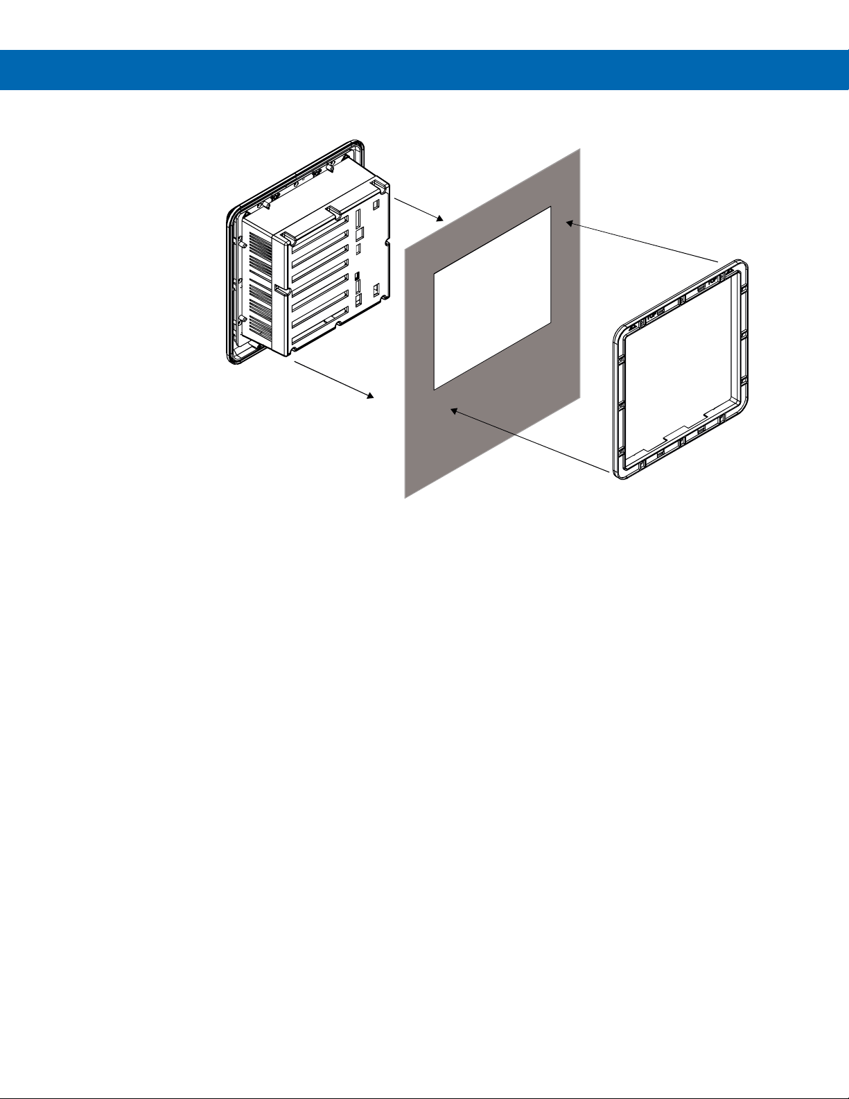
• Prepare panel cutout per the dimensions
provided
• Locate the panel mounting bracket and screws
• Inspect the controller to assure the gasket is
securely in place
• Insert controller in the panel cutout, the latches
on the top and bottom should hold it in place
• Insert the panel mounting bracket from the back
of the panel, observe the orientation of the piece
marked TOP
• Install the 12 screws provided
Figure 1. Front Panel Mount Dimensions
Figure 2. Panel Cutout Dimensions
16
Find Quality Products Online at: [email protected]
www.GlobalTestSupply.com
Page 17
PD9000 ConsoliDator+ Multivariable Controller
Panel
Panel Mounting
Bracket
Notes:
1. Panel cutout: 10.0" x 10.0" ±0.05"
(254 mm x 254 mm ±1.3 mm), see Figure 2.
2. Panel thickness: 0.07" – 0.35"
(1.8 mm – 8.9 mm)
3. Clearance: Allow 6" (152 mm) behind panel
Figure 3. Panel Mount Installation
Instruction Manual
Mounting Dimensions
Figure 4. Panel Mount Overall Dimension
17
Find Quality Products Online at: [email protected]
www.GlobalTestSupply.com
Page 18

PD9000 ConsoliDator+ Multivariable Controller
ConsoliDator+ Configuration Software Installation
We recommend the following sequence for getting the
controller into service:
1. Download the latest version of the
Consolidator+ configuration software from our
website or from the
2. Ex
tract the contents of the
ConsoliDatorPlus2000_Installer.zip file into a
folder in your computer.
included CD.
Instruction Manual
5. Click on Install to start the software installation
process.
6. If your computer does not have the .NET
desktop runtime 3.1, it will be installed
automatically.
3. Double-click on the executable file
ConsoliDatorPlus2000_Installer.exe and follow
the on-screen instructions.
4. Depending on your system, a Windows
message might be displayed:
“Do you want to allow this app from an
unknown publisher to make changes to your
device?”
Click Yes and proceed with the installation.
7. If the .NET desktop runtime 3.1 is already
installed, it will proceed to the installation of the
ConsoliDator+ configuration software.
8. Read and accept the software’s License
Agreement and click on Install.
18
Find Quality Products Online at: [email protected]
www.GlobalTestSupply.com
Page 19

PD9000 ConsoliDator+ Multivariable Controller
9. Click on Finish.
10. After the installation is complete, the following
message is displayed. Click Close to finish. A
ConsoliDator+ icon will be placed on your
desktop.
ConsoliDator+ Software
Instruction Manual
1. Connect one end of the provided USB cable to
the controller and the other end to the
computer.
2. Double-click on the ConsoliDator icon
3. The application will start displaying the System
menu
You are now ready to start using the software to
configure your ConsoliDator+ controller.
The easiest and quickest way to program your
ConsoliDator+ is to use the FREE ConsoliDator+
configuration software available on the included CD
The ConsoliDator+ configuration software is intuitive,
and most customers can get their controller
programmed as they like without even looking in the
manual.
• Only one controller may be connected at a time.
Attaching multiple controllers will cause a conflict
with the controller software.
.
4. Click on Read, at the bottom of the screen, to
read the configuration of the connected
controller. After a read the channels settings
overview is displayed.
5. You can now begin to configure the
ConsoliDator+ for your application, either by
editing the existing settings or by starting fresh
creating a new configuration.
6. Click on Configuration to save files, open
existing files, or to create a new configuration
even without a controller connected.
19
Find Quality Products Online at: [email protected]
www.GlobalTestSupply.com
Page 20
PD9000 ConsoliDator+ Multivariable Controller
Notes:
PI-1
PI-2
PI-3
PI-4
AI-5
AI-6
AI-7
AI-8
AI-1
AI-2 AI-3
AI-4
ANALOG OUTPUTS
ANALOG OUTPUTS
RELAYS
RELAYS
AO-1 AO-2
AO-3
AO-4
AO-5
AO-6
AO-7
AO-8 AO-9
AO-10
RY-1
RY-2
RY-3 RY-4 RY-5
RY-6
RY-7
RY-8
RY-9 RY-10
DIGITAL
INPUTS
DC
PWR
ETHERNET
MICRO
USB
DIGITAL
OUTPUTS
RS-485
AC
PWR
I+ Ex+ I- I+ Ex+ I- I+ Ex+ I- I+ Ex+ I- I+ Ex+ I-
I+ Ex+ I- I+ Ex+ I- I+ Ex+ I- I+ Ex+ I- I+ Ex+ I-
C NC NO C NC NO C NC NO C NC NO C NC NO
C NC NO C NC NO C NC NO C NC NO C NC NO
S- S+ S- S+
mA- mA+ 24V m A- m A+ 24V mA- mA+ 24V m A- m A+ 24V
mA- mA+ 24V mA- m A+ 24V m A- m A+ 24V mA- mA+ 24V
S- S+ S- S+
-
+
Gnd
N
L
G
+
1
2
3
4
5
1
2
3
4
G
D+
D-
G
PULSE INPUTS
4-20 mA INPUTS
4-20 mA INPUTS
Instruction Manual
Connections
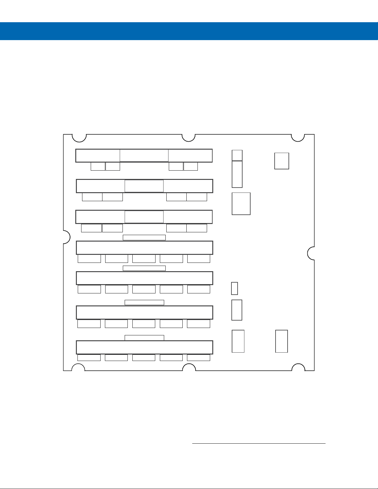
The back panel is labeled with the I/O boards that were installed at the factory. The removable connectors are
labeled with the connection signal for each terminal. The following diagram shows what the back of the model
PD9000-GP-4PI-8AI-10AO-10RY looks like. This model accepts (4) pulse and (8) analog inputs and has
(10) 4-20 mA outputs and (10) relays. (5) digital inputs, (4) digital outputs, RS-485 serial capability and USB
connections are standard on all ConsoliDator+ models. Ethernet is an option.
If all Input / Output slots are used exclusively for one function, the ConsoliDator+ can accept up to (28) isolated
4-20 mA inputs, (28) pulse inputs, (25) isolated 4-20 mA outputs, and (25) relays. If used as a Modbus slave only:
(35) 4-20 mA outputs, (30) relays.
All units can be powered from AC or DC; both power connections can be used at the same time. The DC power
supply can serve as backup power if the voltage is 24 V or less, otherwise the controller will run on DC power.
Find Quality Products Online at: [email protected]
1. Each 4-20 mA input has its own isolated 24 VDC power supply to
2. Each 4-20 mA output has its own isolated 24 VDC power supply to
3. Each relay is Form C and rated at 10 A.
4. Input / output connections are made to removable screw connectors.
5. Every ConsoliDator+ has five digital inputs (additional digital inputs can
6. Every ConsoliDator+ has four digital outputs.
7. Every ConsoliDator+ has RS-485 with Modbus.
8. All ConsoliDator+ models can be powered from either AC or DC
9. Ethernet with Modbus TCP is an option.
10. Micro USB is used for programming the ConsoliDator+.
power the transmitter.
power the output loop.
be obtained by using the Pulse Inputs).
Power.
Figure 5. Connection Terminals for a PD9000-GP-4PI-8AI-10AO-10RY
www.GlobalTestSupply.com
• Use copper wire with 60°C or 60/75°C insulation for
all line voltage connections. Observe all safety
regulations. Electrical wiring should be performed in
accordance with all applicable national, state, and
local codes to prevent damage to the controller and
ensure personnel safety.
20
Page 21
PD9000 ConsoliDator+ Multivariable Controller
mA- mA+ 24V
-
Pwr+
3-Wire 4-20 mA
Transmitter
Analog Input
mA- mA+ 24V
-
2-Wire 4-20 mA
Transmitter
Analog Input
Signal
Pwr+
mA- mA+ 24V
- + -+
External
Power
Supply
2-Wire
4-20 mA
Transmitter
Analog Input
mA- mA+ 24V
- +
2-Wire 4-20 mA
Self-Powered
Transmitter
Analog Input
mA- mA+ 24V
3-Wire 4-20 mA
Transmitter
Analog Input
+
External
Power Supply
Signal +
Power +
Signal -
-
Power Connections
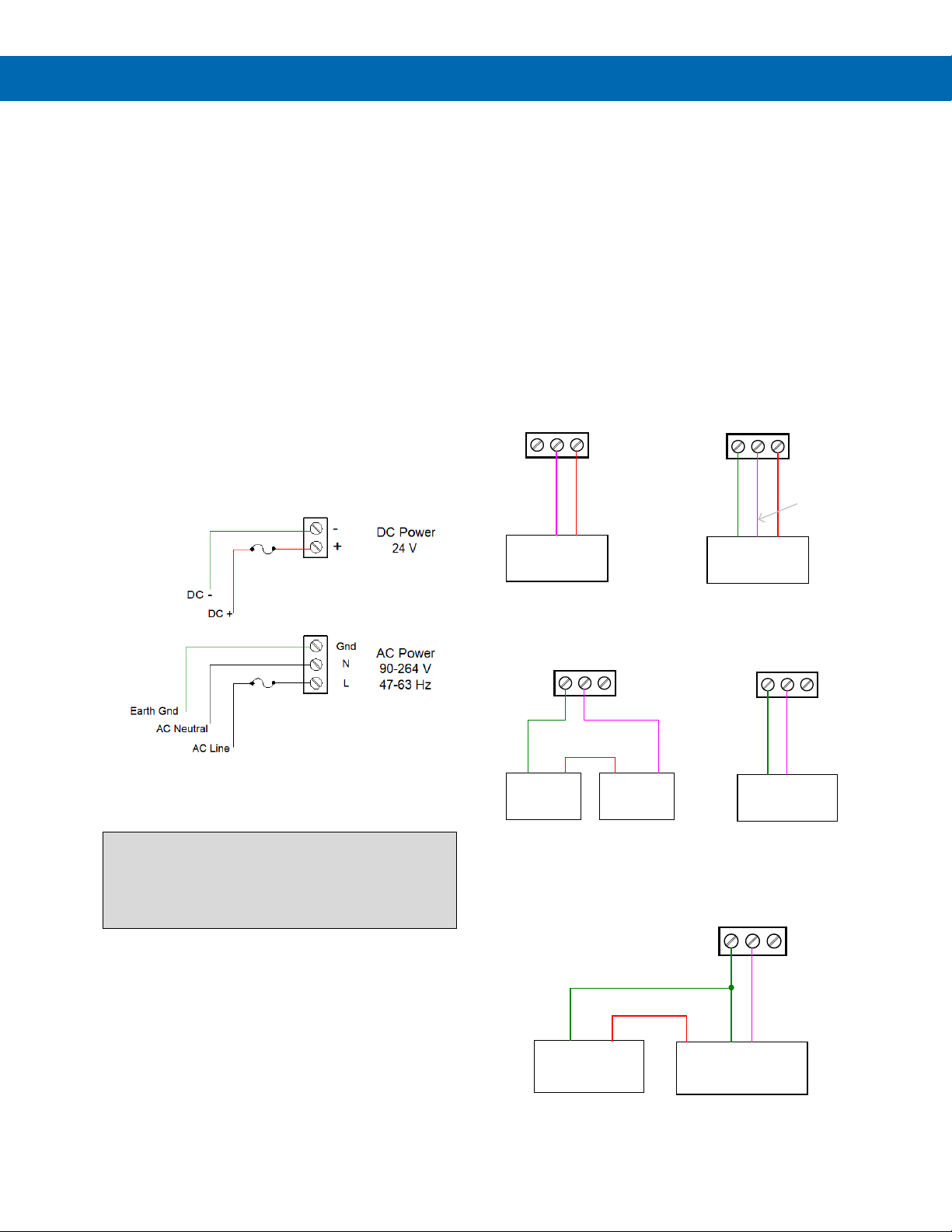
Power connections are made to one of the power
terminal connectors. All units are capable of being
powered either by AC or by DC for the ranges
specified.
90-264 VAC Power
• Use three-terminal power connector as
shown in Figure 6.
• Unit is protected internally with 1.25 A auto-
resettable fuse. 2 A max, slow blow,
250 V min, UL Recognized external fuse
recommended.
24 VDC Power ± 10%
• Use two-terminal power connector as shown
in Figure 6.
• Unit is protected internally with 3.7 A auto-
resettable fuse. 4 A max, slow blow,
50 V min, UL Recognized external fuse
recommended.
Instruction Manual
Isolated Input Signal Connections
Isolated input signal connections are made to
removable screw terminal connectors, which are
labeled individually on the back panel of the
controller. The back panel shows the type of input
card installed in each slot (The top slot is #1 and the
bottom is #7). Individual inputs are referenced as PI-1
to PI-4 for pulse inputs and AI-1 to AI-4, AI-5 to AI-8,
etc for analog inputs.
4-20 mA Analog Input Connections
Analog 4-20 Input connections are made to screw
terminal connectors (two inputs per connector). The
following figures show examples for typical
applications. Each of the 4-20 mA inputs may be
connected in any of the modes shown below.
Figure 6. Power Connections
Note:
The controller may be powered by AC voltage with
the DC power connection used as backup power. The
DC power supply must be 24 V or less to work as
backup; otherwise the controller runs on DC power.
Figure 7. Transmitters Powered by ConsoliDator+
Isolated 24 VDC Power Supply
Figure 8. Transmitter Powered by Ext. Supply
or Self-Powered
Find Quality Products Online at: [email protected]
Figure 9. 3-Wire Transmitters Powered Externally
21
www.GlobalTestSupply.com
Page 22
PD9000 ConsoliDator+ Multivariable Controller
S- S+
Pulse Input
+
-
Signal Source
G
Digital Inputs
+5V
1
2
3
4
5
Switch
Contact
Live
Signal
C
E
B
I+ Ex+ I-
mA-mA+
Analog Output
Remote Display,
Chart Recorder, Etc
I+ Ex+ I-
mA-mA+
Analog Output
Remote Display,
Chart Recorder, Etc
External
Power Supply
+
-
Digital Outputs
1
2
3
4
G
Alarm
Annunciator
Load
V
AC
Flow Meter Pulse Input Connections
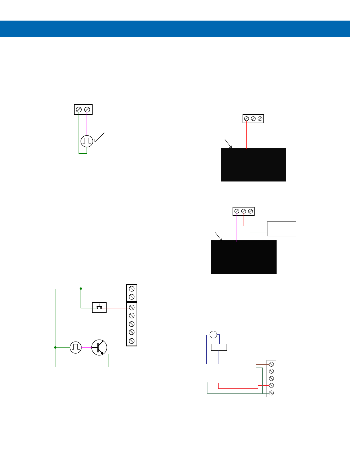
Flow Meter Pulse Inputs are wired to four-terminal
connectors (two inputs per connector). A square
waveform is used in the illustration, but the input is
capable of reading many other types of signals within
the voltage and frequency ranges specified.
Figure 10. Flow Meter Pulse Input Connections
Digital Input Connections
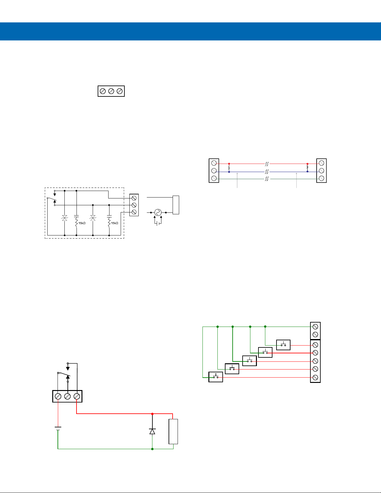
Inputs are wired between terminals 1-5 of the digital
input connector and the G terminal of the 2-position
connector above the digital inputs. Normally open
switch contacts may be used as shown in
The diagram also shows a Digital Input using an NPN
open collector transistor output from a live signal.
Logic LO or switch closure appearing across the
terminals is interpreted as ON. When using an open
collector transistor, a logic HI at the base (marked “B”
Figure 11) will be interpreted as ON. The 2-position
in
connector has a +5 V terminal that may be used to
provide excitation to some sensors requiring more
than the pull-up provided on each digital input
terminal.
Figure 11.
Instruction Manual
Analog Output Connections
The following figures show examples for isolated
4-20 mA transmitter output connections. Terminal
connectors are labeled individually. The analog
outputs are isolated from each other and from the
inputs. They are powered internally to provide an
active 4-20 mA output loop. The outputs may be
powered externally by connecting the positive voltage
to the Ex+ terminal.
Figure 12. Active 4-20 mA Output Powered by
Controller
Figure 13. Passive 4-20 mA Output Powered
by External Supply
Note: Analog inputs and outputs are isolated from each other
Digital Output Connections
The digital outputs may be used to drive digital inputs,
alarm annunciators, or other devices such as solidstate relays that can be driven with low voltage signals.
Figure 11. Digital Input from Switch Closure
Find Quality Products Online at: [email protected]
and Live Signal
www.GlobalTestSupply.com
Figure 14. Digital Outputs Driving 5 V Solid State
Relay
22
Page 23
PD9000 ConsoliDator+ Multivariable Controller
Connections to Power Gas Detector
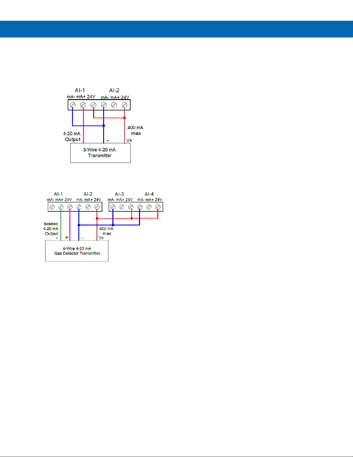
Some sensors requiring more than 200 mA of
excitation current can be powered by the
ConsoliDator+ by connecting two or more power
supplies in parallel as shown in the following
diagrams.
Figure 15. Two Supplies in Parallel Powering
3-Wire Transmitter
Instruction Manual
Figure 16. Powering 4-Wire Gas Detector &
Isolated 4-20 mA Output
23
Find Quality Products Online at: [email protected]
www.GlobalTestSupply.com
Page 24
PD9000 ConsoliDator+ Multivariable Controller
C NC NO
Relay Output
C
NC NO
+
-
L
O
A
D
G
Digital Inputs
+5V
1
2
3
4
5
External Keypad
C
NC
NO
L
O
A
D
-
+
Inter nal Protection
MOV
MOV
4.7nF
4.7nF
ConsoliDator+
RS-485 Port
D+
D-
G
120 ohm
B+
A-
G
120 ohm
Last M odbus
Device
Terminat ing Res istor
Terminat ing Res istor
Instruction Manual
Relay Connections
Relay connections are made to three-terminal connectors
labeled individually. There are five relays per card.
Figure 17. Relay Connections
Switching Inductive Loads
The ConsoliDator+ has internal circuitry to protect the relays
from inductive loads, however, the use of external
suppressors (snubbers) is strongly recommended when
switching inductive loads to prevent disrupting the
microprocessor’s operation. The suppressors also prolong
the life of the relay contacts. Suppression can be obtained
with resistor-capacitor (RC) networks assembled by the user
or purchased as complete assemblies. Refer to the following
circuits for RC network assembly and installation.
Figure 18. AC and DC Internal Inductive Loads
Protection
For addi
follows:
R: 0.5 to 1 Ω for each volt across the contacts
C: 0.5 to 1 µF for each amp through closed contacts
Notes:
1. Use capacitors rated for 250 VAC.
2. RC networks may affect load release time of
3. Install the RC network at the instrument's relay
tional external protection choose R and C as
solenoid loads. Check to confirm proper operation.
screw terminals. An RC network may also be
installed across the load. Experiment for best
results.
RC Networks Available from Precision Digital
RC networks are available from Precision Digital and should
be applied to each relay contact switching an inductive load.
Part number: PDX6901.
Serial Communication Connections
The RS-485 port for serial communication (using Modbus
protocol) has three terminals labeled D+, D-, and G. It is
strongly recommended to use three-wire shielded cable and
to always connect the ground terminal to the other
equipment’s ground to avoid differential voltage between the
systems. Distances up to 4000 feet can be reached with
RS-485. Up to 32 Modbus devices may be connected to a
single RS-485 bus.
Figure 20. Serial Connections
Ethernet Option
The Ethernet port is available on the RJ45 connector. This
allows the ConsoliDator+ to connect to a local area network.
The Ethernet port option is fully configured using the
Lantronix DeviceInstaller software, available for download
from the Lantronix’s Website
specifications, page 53 for setup using the ConsoliDator+
software, and page 54 for complete Ethernet Port Setup.
.
See page 15 fo
r
External Keypad Connections
Normally open pushbuttons may be wired to the digital
inputs connector for use when the front panel of the
controller is not accessible. The external keys may be
assigned to replicate the Menu and F1-F4 function keys.
Use diode with a reverse
breakdown voltage two to three
times the circuit voltage and
forward current at least as large
Figure 21. External Keypad Connections
as the load current.
Find Quality Products Online at: [email protected]
Figure 19. Low Voltage DC Loads Protection
www.GlobalTestSupply.com
24
Page 25
PD9000 ConsoliDator+ Multivariable Controller
Right-key →
Left-key ←
Down-key ↓
Up-key ↑
←|
|→
X→
←X
View alarm alerts, manually controlled
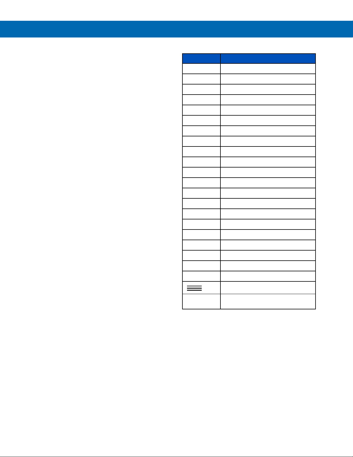
Navigating and Editing
The device displays various screens throughout
programming and operation. Functions are
programmed within their respective menu screens
and in many cases are accompanied by user
prompts.
Soft-Keys and Buttons
The unit is equipped with five buttons located below
the display. The function of each button corresponds
to its soft-key, which appears at the bottom of the
screen. Buttons assume different functions, which
change according to the screen in view.
Screen Navigation
Menu Navigation
Instruction Manual
Key Action
Menu Enter menu
Step into menu/setting
Exit/go back
Next screen/channel/setting
Previous screen/channel/setting
Stop Stop automatic scan
Scan Scan screens automatically
Ack Acknowledge alarms/relays
Reset Reset total/max/min
Setup Enter the Setup menu
Edit Modify selection
Selections are highlighted with green background for
illustration purposes. The keys below are used to
navigate through menus and edit settings. Other
special keys appear throughout the programming
process.
Note:
This is not a touch-screen display; the
pushbuttons must be used to activate the soft-key
Enter Execute keypad entry
Ok Accept setting change
Save Save all settings in view
Cancel Discard changes
Delete Delete channel/item
New Create new channel/alarm
Alert!
Move cursor left
Move cursor right
Delete to the right
Delete to the left
Access additional settings or actions
outputs, and simulated parameters
Find Quality Products Online at: [email protected]
www.GlobalTestSupply.com
25
Page 26

PD9000 ConsoliDator+ Multivariable Controller
Setup
Setup and Programming
There is no need to recalibrate the instrument when first received from the factory.
The device is factory calibrated prior to shipment, for all input types and 4-20 mA outputs. The calibration
equipment is certified to NIST standards.
Overview
Setup and programming are done through the front panel buttons or with the ConsoliDator+
Software. After power and signal connections have been completed and verified, apply power to
the instrument.
Inputs, outputs, channels, and relays are configured individually. It is recommended that all inputs
be configured before channels, outputs, and relays are programmed.
Shown below are typical screens for tank level applications. Actual screens will vary according to
the selected configuration. Screens may be edited, deleted, or added to fit the application.
For information on soft-keys and button functions, see
Soft-Keys and Buttons on page 25.
Instruction Manual
Typical screen view displaying 4 channels and 4
bargraphs representing the values of each channel.
Press the Menu key to begin setup and programming
The View screen allows a user to view all the settings and values for Channels, Totals, Timers, etc.
To program the instrument, press the
key.
Typical screen view displaying 8 channels and 8
bargraphs representing the values of each channel.
26
Find Quality Products Online at: [email protected]
www.GlobalTestSupply.com
Page 27

PD9000 ConsoliDator+ Multivariable Controller
Setup Menu
Instruction Manual
The Setup menu is the starting point during the programming process for setting up Channels, Totals, Timers,
Alarms, Inputs, Outputs, Screens, and System settings. The number of channels shown on this screen is determined
by the number of channels previously configured. More channels may be added to the list, by selecting New in the
Setup Channels menu.
Press Right Arrow key to step into channels. Press New key to create a new channel.
Go to page 31 for details.
27
Find Quality Products Online at: [email protected]
www.GlobalTestSupply.com
Page 28

PD9000 ConsoliDator+ Multivariable Controller
Instruction Manual
Channel Parameters
1. Channel tag: Editable
2. Auto-generated
channel #: Use to reorder channels
3. Function*: This is the
function applied to the
input source
Scale
• Scale Factor
• Scale Linear 2-Pt
• Scale Multi-Point
• Scale Square Root
• Scale Exponent
• Round Horz Tank*
• Units Conversion**
Math
• Constant
• Summation
• Difference
• Absolute
Difference
• Absolute Value
• Average
• Weighted Average
• Multiply
• Divide
• % Efficiency
*Round Horz Tank: Available
only if Input units is distance
(height)
**Use for custom units
Compare
Measure
Filter
Control
Relays
Modbus
Other
• Greatest
• Least
• Tare
• Maximum
• Minimum
• Percent (Bargraph)
• Duration
• Rate of Change
• Window Average
• IIR (First Order)
• Cutoff
• Limits
• Sampler
• On-Off Control
• Select A or B
• Schedule
• Cycle Count
• Runtime
• Time Since Read
• Time Since Write
• None (Reserved)
See Channel & Math
Functions on page 12 for
details.
4. Input: Source for the
channel (PV)
• mA Input (4-20 mA)
• Pulse Input
• Digital Input
• Modbus Input
• Channel
• Total
• Timer
• Alarm
• mA Output
• Relay Output
• Digital Output
• Modbus Output
5. Units: Engineering
units / time or none
• None
• Time
• Distance (Height)
• Volume
• Pressure
• Weight
• Temperature
• Percent
• Amps
• Volts
• Counts
• Logic
• Custom
Note: Units conversion is
available for all
units.
6. Decimals: Number of
decimals for the PV
7. Input scale: Enter
input and output values
8. Cutoff: PV goes to
zero below the cutoff
value
9. Soft keys: These
change based on the
screen in place
10. Bargraph scale: Set
the 0 and 100% values
11. Display bargraph:
Display on the screen
12. Colors: Select the
bargraph & panel
colors
28
Find Quality Products Online at: [email protected]
www.GlobalTestSupply.com
Page 29
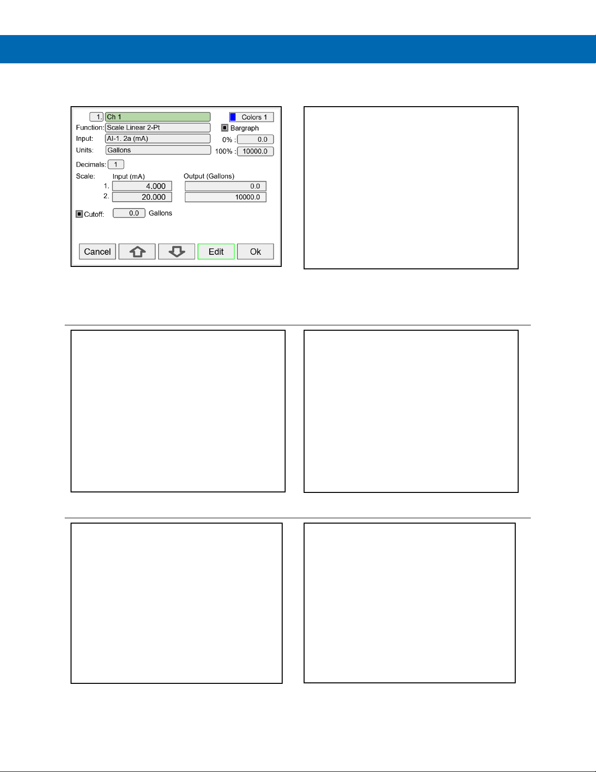
PD9000 ConsoliDator+ Multivariable Controller
Data Entry Keypad
The system provides a soft keypad for entering values and tags; it contains numbers, alpha characters, and symbols.
Instruction Manual
Press Edit key to start editing the channel configuration.
The green background indicates the field to be edited.
Press Edit key again to change the channel’s tag, this
opens the data entry keypad.
To change the character set, navigate to the three dots
and press the key indicating the next set of characters.
Use the Down Arrow key to navigate to the keypad. Use
and | keys to move the cursor and use the X
the |
key to delete characters. To enter characters in the
selected text field, use the arrow keys to navigate
through the popup keypad.
To enter symbols, press the three dots and select the
desired symbol.
When done typing the characters in the selected field,
press the Enter key.
Find Quality Products Online at: [email protected]
www.GlobalTestSupply.com
To enter numbers, select the numeric keypad, move the
cursor to the insertion point and enter the number using
the soft keys.
29
Page 30
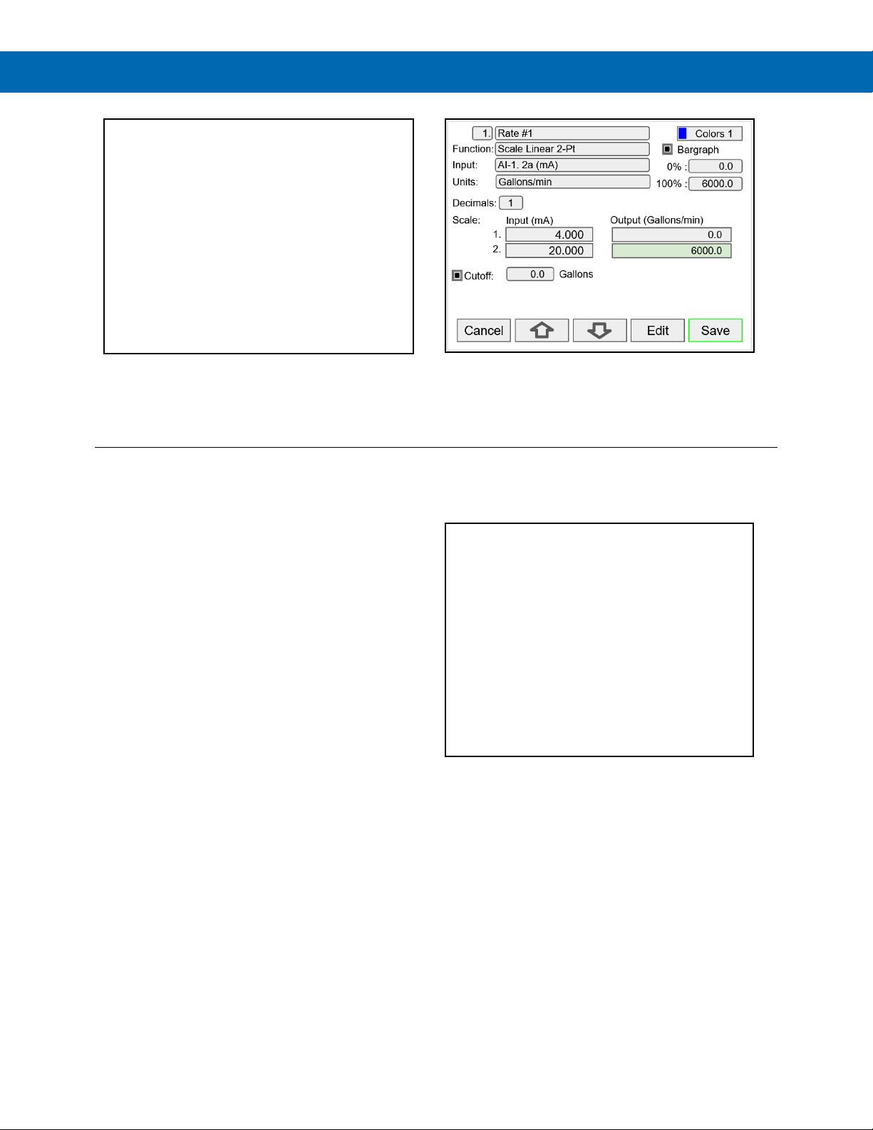
PD9000 ConsoliDator+ Multivariable Controller
the input scaling.
Instruction Manual
Press Enter to accept the changes.
Press the Save key to save the changes. The bargraph
is automatically adjusted to reflect the scale entered.
The bargraph scaling may be changed without affecting
Setup Channels
The Setup Channels menu is used to configure each channel, enter a tag, select the input source,
scale the input, and program other settings that will determine the channel’s processing capabilities.
• Use the Arrow keys to navigate through the
existing channels
• Press the New key to create a new channel
• Press the Right Arrow key to step into the
channel setup
• Press the Edit key to make changes to a
particular channel
• Press the Delete key to delete a channel
Find Quality Products Online at: [email protected]
www.GlobalTestSupply.com
30
Page 31
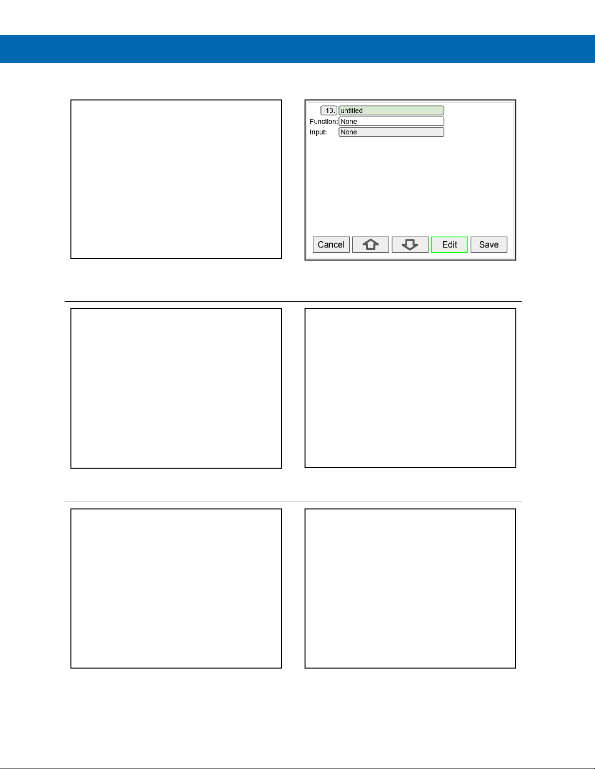
PD9000 ConsoliDator+ Multivariable Controller
Create New Channel
Instruction Manual
To create a new channel press the New key.
Select the function to be applied to the input and press
the Ok key.
Press the Edit key to edit the channel tag and other
settings. Press the Up and Down arrow keys to select
setting to be edited.
Select the input source for the channel.
Select the engineering units, decimal point, enter scale
points and press the Ok key.
Find Quality Products Online at: [email protected]
www.GlobalTestSupply.com
Select number of decimals, scale the input, enter the
cutoff value, select colors for bargraph and text,
confirm the bargraph’s scale, and press Save.
31
Page 32

PD9000 ConsoliDator+ Multivariable Controller
Instruction Manual
Bargraph, Background & Text Colors
To select a channel color pattern, navigate to the Colors
setting and press the Colors key.
Select a color pattern or press the Edit key to make
changes to the colors’ tag, text, background, and
bargraph.
Use the arrow keys to navigate the settings and press
Edit to make changes.
Select the desired color and press Ok. Navigate to the
other settings and make the necessary changes.
Find Quality Products Online at: [email protected]
www.GlobalTestSupply.com
Press Edit to change text color, this applies to the
channel tag, units, and value.
Press Save to save the color changes. Press Select to
apply the color pattern to the channel.
The Manage button is used to move or delete colors.
32
Page 33
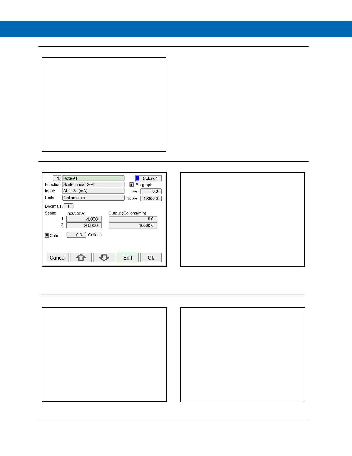
PD9000 ConsoliDator+ Multivariable Controller
Live Calibration
Edit Channel
Delete Channel
The Live Calibration feature is used to calibrate a
channel by applying a live calibration signal.
Instruction Manual
1. From the Setup menu, navigate to the
channel to be calibrated.
2. Go to Input 1 entry box
3. Apply Input 1 signal from sensor or calibrator
4. Press & hold the Edit key and press the Live
key a few time until a stable reading is
displayed.
5. Release the Edit key; the input 1 value has
been captured.
6. Repeat the steps above for the additional
inputs to be calibrated.
7. Adjust the output values according to the
calibrated inputs.
8. Press Save.
To edit a channel press the Edit key and navigate to the
setting you want to change, press Edit again and make
the changes required.
To delete a channel, press the Delete key and follow the
instructions.
After making all the changes, press the Save key.
Press the Ok key to delete the channel or the Cancel
key to cancel delete action.
33
Find Quality Products Online at: [email protected]
www.GlobalTestSupply.com
Page 34
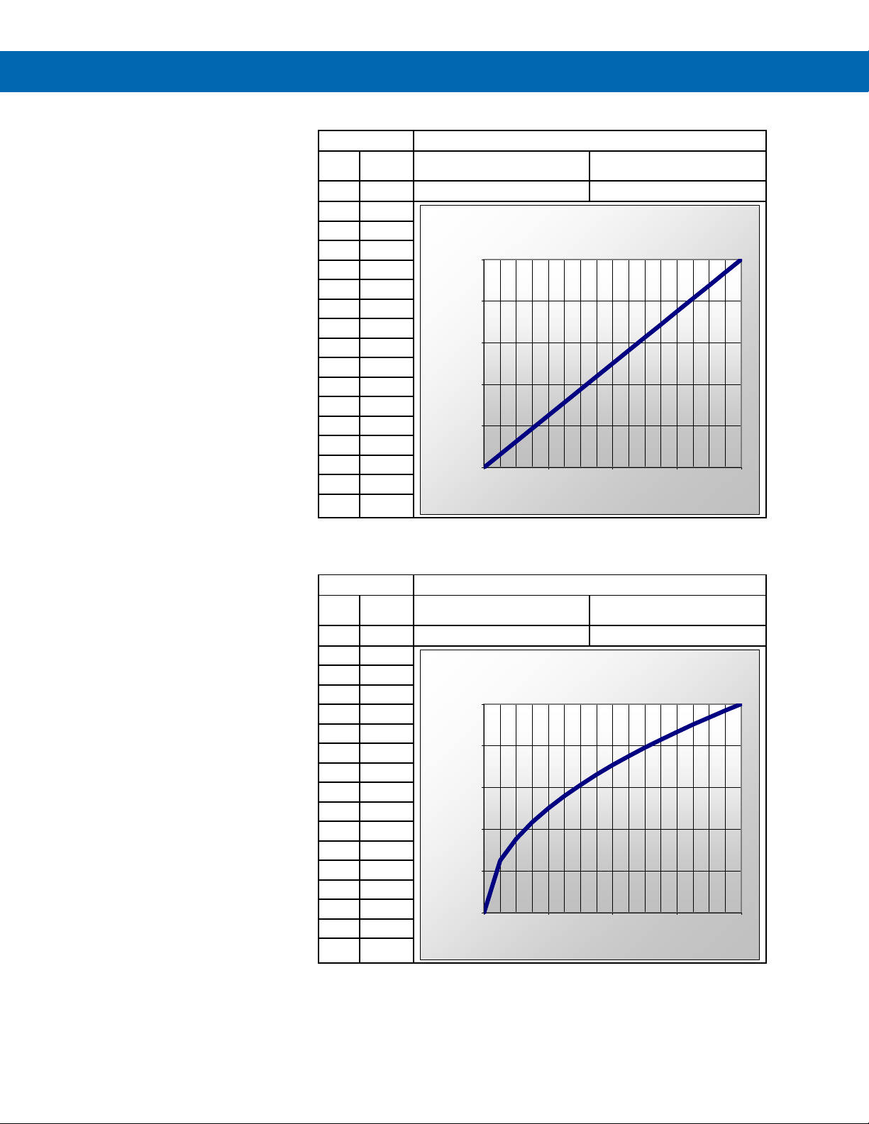
PD9000 ConsoliDator+ Multivariable Controller
Process
Scaling Parameters
mA Input:
Low Value:
mA Input:
High Value:
Process
Scaling Parameters
mA Input:
Low Value:
mA Input:
20.000
High Value:
100.00
2-Point Linear Scaling
Linear mode refers to basic 2-point
scaling of a 4-20 mA signal in
engineering units. The graph in
Figure 22 shows the display
response based on example
scaling parameters. For this mode
select [Scale Linear 2-Pt] from
Function options, then enter your
scaling parameters.
Input
(mA)
10.00 37.50
11.00 43.75
12.00 50.00
13.00 56.25
14.00 62.50
15.00 68.75
16.00
17.00 81.25
18.00 87.50
19.00 93.75
20.00 100.00
Output
(%)
4.00 0.00
5.00 6.25
6.00 12.50
7.00 18.75
8.00 25.00
9.00 31.25
75.00
Output (%)
Figure 22. Linear Response Graph
Instruction Manual
4.000
20.000
Linear Response
100.00
80.00
60.00
40.00
20.00
0.00
4.00 8.00 12.00 16.00 20.00
mA Input
0.00
100.00
Square Root Scaling
Square root mode refers to 2-point
scaling with square root extraction
typically used to linearize the signal
from a differential pressure
transmitter and display the flow rate
in engineering units. The graph in
Figure 23 shows the display
response based on example
scaling parameters. For this mode
select [Scale Square Root] from
Function options.
The square root mode supports
low-flow cutoff which can be used
to suppress readings below a
programmed value. Below the
cutoff value, the controller will
display “0”.
Input
Display
(mA)
4.00 0.00
5.00 25.00
6.00 35.36
7.00 43.30
8.00 50.00
9.00 55.90
10.00 61.24
11.00 66.14
12.00 70.71
13.00 75.00
14.00 79.06
15.00 82.92
16.00 86.60
17.00 90.14
18.00 93.54
19.00 96.82
20.00 100.00
(%)
4.000
Square Root Response
100.00
80.00
60.00
Output (%)
40.00
20.00
0.00
4.00 8.00 12.00 16.00 20.00
mA Input
Figure 23. Square Root Response Graph
0.00
34
Find Quality Products Online at: [email protected]
www.GlobalTestSupply.com
Page 35
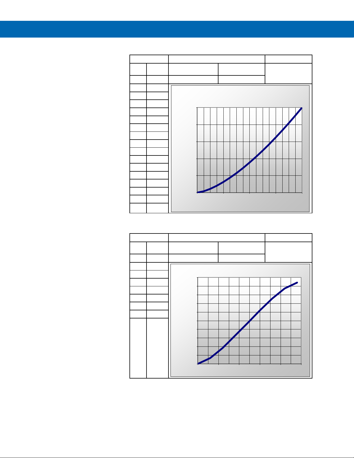
PD9000 ConsoliDator+ Multivariable Controller
Process
Scaling Parameters
Exponent
mA Input:
Low Value:
mA Input:
20.000
High Value:
100.00
Process
Parameters
Tank Dimensions
Low Value:
Diameter: 48.0 Inch
120.0 Inch
0.00
High Value:
67.82
183.78
470.01
618.05
756.25
872.21
940.03
Scale Exponent
Exponent mode refers to 2-point
scaling with programmable
exponent, typically used in openchannel flow applications using
weirs and flumes to linearize the
signal from a level transmitter and
display the flow rate in engineering
units. The graph in
Figure 24 shows
the display response based on
example parameters and exponent
of “1.5”. For this mode select [Scale
Exponent] from Function options.
The exponent mode supports lowflow cutoff which can be used to
suppress readings below a
programmed value. Below the
cutoff value, the controller will
display “0”.
Input
(mA)
10.00 22.96
11.00 28.94
12.00 35.36
13.00 42.19
14.00
15.00 57.00
16.00 64.95
17.00 73.24
18.00 81.85
19.00 90.77
20.00 100.00
Output
(%)
4.00 0.00
5.00 1.56
6.00 4.42
7.00 8.12
8.00 12.50
9.00 17.47
49.41
Output (%)
Instruction Manual
4.000
Exponent Response
100.00
80.00
60.00
40.00
20.00
0.00
4.00 8.00 12.00 16.00 20.00
0.00
mA Input
1.500
Round Horizontal Tank
The Round Horizontal Tank (RHT)
function calculates the volume of
round tank with flat ends, based on
the diameter and length dimensions
of the tank.
The input source for the channel
calculating the volume must be a
level channel with units of distance
(height). The RHT function
linearizes the signal from a level
transmitter and displays the volume
in engineering units. The graph in
Figure 25 shows the display
response based on tank example:
Diameter = 48.00 inches
Length = 120.00 inches
For this mode select [Round Horz
Tank] from Function options.
Input
(Inch)
0.00
6.00
12.00
24.00
30.00
36.00
42.00
48.00
Figure 24. Exponent Response Graph
Output
(US GAL)
Level Input 1: 0.00
Level Input 2: 48.00
1000.0
900.0
800.0
700.0
600.0
500.0
400.0
Volume US GAL
300.0
200.0
100.0
0.0
0.0 10.0 20.0 30.0 40.0 50.0
0.00
940.03
RHT Response
Input (Inches)
Figure 25. Round Horizontal Tank Volume Graph
Length:
Find Quality Products Online at: [email protected]
www.GlobalTestSupply.com
35
Page 36

PD9000 ConsoliDator+ Multivariable Controller
Open Channel Flow Application
The PD9000, in combination with
an ultrasonic level transmitter,
makes for a practical way to
measure and display open channel
flow rate and total in most weirs
and flumes and take periodic
samples. All the user needs to do is
enter the exponent for the weir or
flume into the PD9000 and the
PD9000 automatically raises the
input signal to that power. Sampling
can be based on the total flow or
the flow rate. For instance, to
display open channel flow rate and
total from a 3-inch Parshall flume
and take a one pint sample every
100,000 gallons, the user would
program the PD9000 as shown in
the table above right.
Function Desire Programming
Open Channel Flow 3" Parshall flume Set Programmable Exponent to 1.547
Flow Rate 1
Total 1 Millions of Gallons
Sampling
Channel 2
Sampling
Relay 1
Total 2
Non-Resettable
Screen
Millions of Gallons per
Day (MGD)
Take a 1 pint sample
every 100,000 gallons
Turn valve on to take a
sample
Program controller so
total 2 can never be reset
Display flow rate, totals,
and relay status
Instruction Manual
Set 4 mA: 0
Set 20 mA: 3.508
Create custom unit: MG
Time base: day
Input: Flow Rate 1
Select unit = MG
Input: Total 1
Function: Sampler
Sample Interval: 0.1 MG
Sample Time: 10 sec
Input: Channel 2 (On / Off)
Use a timer to count the time needed to
take the sample
Input: Flow Rate 1
Set total 2 as non-resettable total
Set a screen to display rate, total 1, total 2,
and relay status.
Figure 26. Total Relay Sampling Operation
36
Find Quality Products Online at: [email protected]
www.GlobalTestSupply.com
Page 37

PD9000 ConsoliDator+ Multivariable Controller
complex math functions. Math channels can be the
Application: % Efficiency
Setup Math Functions
There are many math functions that can be applied to
any channel, which allows the execution of simple or
source for other math channels, totalizers, alarms, and
analog outputs.
List of Math Functions
1. Constant
2. Summation
3. Difference
4. Absolute Difference
5. Absolute Value
6. Average*
7. Weighted Average
8. Multiply
9. Divide
10. % Efficiency
*Average can be used for applications requiring redundancy
sensors by selecting the Exclude Fail Input feature. Both
4-20 mA inputs must be set to break below a fail level value.
Additional Functions
Scale
K-Factor
Scale Factor
Scale Linear 2-Pt
Scale Multi-Point
Scale Square Root
Scale Exponent
Round Horz Tank
Units Conversion
Compare
Greatest
Least
Measure
Tare
Maximum
Minimum
Percent (Bargraph)
Duration
Rate of Change
Filter
Window Average
IIR (First Order)
Cutoff
Limits
Control
Sampler
On-Off Control
Select (A or B)
Schedule
Relays
Cycle Count
Runtime
Modbus
Time Since Read
Time Since Write
Instruction Manual
Description: Calculate the VOC Destruction Efficiency
in a Thermal Oxidizer
Thermal Oxidizer Efficiency =
(Inlet VOC – Outlet VOC) / Inlet VOC
4-20mA output = 0-100% efficient
Efficiency = ((Ch1 – Ch2)/Ch1)*100
Ch1 = Inlet VOC
Ch2 = Outlet VOC
AO-1 Source = Ch 20. VOC %Efficiency
AO-1 Scale: 4-20 mA = 0-100% efficiency
VOC: Volatile Organic Components
Select math function for % Efficiency and press Ok.
Enter the input sources for the math function, select the
units and number of decimals, and press Ok and Save.
37
Find Quality Products Online at: [email protected]
www.GlobalTestSupply.com
Page 38

PD9000 ConsoliDator+ Multivariable Controller
Setup Totalizers
channel is
integrated over the specified time unit to generate an
tions are
Setup Total with Rate Source
The totalizers are setup the same way as the channels.
The rate from an analog or pulse input
accumulated total that can be configured to count up or
count down. Each total may be configured as “nonresettable”*, which means the total reset func
not available for it.
The pulse inputs can be either integrated from a rate
channel or they can be directly totalized based on the
pulse count and K-Factor value; this is the most accurate
method because every pulse is counted.
*Note:
The non-resettable function can be disabled by the user
at any time, after unlocking a password-protected
controller.
Instruction Manual
Select the rate input channel for the total and press Ok.
Setup Total with Pulse Input Source
Pulse inputs can be totalized directly without the need to
create a rate channel.
Select total units, count up or down, enter preset and
roll-over values, and select non-resettable if required.
After pressing Save, press Yes to reset the total to the
preset value.
Select the units and enter the K-Factor provided by the
flow meter manufacturer.
38
Find Quality Products Online at: [email protected]
www.GlobalTestSupply.com
Page 39

PD9000 ConsoliDator+ Multivariable Controller
Instruction Manual
Setup Timers
Up to 32 timers may be setup to control and monitor various processes. The timers may be triggered by any input or
output, such as an analog input rising above a certain threshold or a digital input going from low to high.
Timer Automatic Actions
The automatic timer actions are:
Power Up: Timer action on power up
Error: Timer action when an error is detected
Reset: Event that causes the timer to reset
Start: Event that triggers the timer to start
Stop: Event that causes the timer to stop
Timer Function Keys & Digital Inputs
The function keys and digital inputs may be used to start,
stop, and reset the timers, regardless of the automatic
actions selected.
Time Format
The time format is hh:mm:ss with 0 decimals selected.
If decimal is other than 0, the time is displayed in
seconds with the number of decimals selected.
Count Down Timer
Select count down and enter the starting time count.
Timer Bargraph
The bargraph scaling follows the time format selected
based on decimal point.
Timer Colors
Select the colors for normal and alarm conditions.
Timer Alarms
Alarms may be setup to trigger on timer values,
counting up or down. Go to the Alarms menu and select
a timer as the source for the alarm.
39
Find Quality Products Online at: [email protected]
www.GlobalTestSupply.com
Page 40
PD9000 ConsoliDator+ Multivariable Controller
Setup Alarms
can be driven by a single channel, multiple channels,
digital inputs, time interval, or a combination of other
Reset (Ack)
Ack Anytime
Automatic
The system is capable of handling up to 64 alarms; they
alarms into logic AND & logic OR alarms. Set and reset
point values determine if it is a high or low alarm and the
dead band. Alarms may be setup as latching or nonlatching (automatic) with on and off time delays.
1. Tag: 15-character user-defined
2. Type: Select alarm type
• Single Source
• Multi-Source
• Time Interval
• Alarms OR
• Alarm AND
3. Input: This will depend on type selected
Type: Single and Multi-Source
• Digital
• Modbus
• Channel
• Total
• Timer
Type: Alarms AND & OR
Inputs: Other alarms
4. Automatic: Resets when PV crosses the reset point
5. Ack Anytime (Latching): Ack alarm anytime
6. Break: Alarm status when sensor/comm. break is
detected (e.g. Input < 0.01 mA)
• Alarm On
• Alarm Off
• Stay (Maintain the state before the break)
7. On/Off Delays
Multi-Source Alarm
This alarm type behaves as a logic OR; if
any of the sources crosses the set point,
the alarm goes on.
If the first source is digital (logic), only
sources with digital value (on = 1, off = 0)
are available for selection.
If the first source is a PV channel or timer,
digital inputs may be added as source.
Instruction Manual
Automatic reset and Ack anytime
Relay assigned to Horn activates on alarm condition
Automatic only: Alarm resets automatically at the
reset point
Latching & Non-Latching Alarms
Auto & Manual X X
Auto Only 0 X
Manual Only X 0
Manual Only
After Cleared
Find Quality Products Online at: [email protected]
0 0
www.GlobalTestSupply.com
Latching: Acknowledge only after the alarm
condition has cleared
Manual Ack (Latching): Select Ack Anytime only
40
Page 41

PD9000 ConsoliDator+ Multivariable Controller
Logic AND Alarm
Logic NOR & NAND Alarms
Any input alarm may be inversed (Not) to create a
Logic OR Alarm
The inputs for the logic OR alarm are any existing
alarms, regardless of the source or type.
Any active alarm in the group triggers the OR alarm.
The OR alarm can be used as a summary alarm.
The inputs for the logic AND alarm are any existing
alarm, regardless of the source or type.
All alarms in the group must be active to trigger the AND
alarm.
Instruction Manual
To create a NOR alarm, select an existing OR alarm and
apply the Not function available during Setup – Edit.
The same applies to the NAND alarm.
specialized alarm logic.
41
Find Quality Products Online at: [email protected]
www.GlobalTestSupply.com
Page 42
PD9000 ConsoliDator+ Multivariable Controller
Setup 4-20 mA Inputs
Instruction Manual
Setup Inputs
The Setup Inputs screen is used to configure the
hardware inputs, assigning a user-defined tag, and
setting filter values.
The top line, for each input, shows the slot # and input
location (2b = slot #2, second input from the left). It also
shows the actual current input.
The next line shows the input type and # (AI-2) with the
default tag, which can be changed at any time.
• Filter*: Select filter time
• Bypass: If the signal change is greater than the
bypass value, the reading jumps to the actual value
± Bypass % of full scale.
• Glitch Filter: Eliminates short duration noise spikes
• Break Below: Set the mA value at which a break is
reported to the system.
• Disable Input Channel: This turns off the power to
the input, but the settings are saved for future use.
This should only be used to save power on unused
inputs.
*Need more filtering?
If you need a more stable reading,
select IIR 16 sec or IIR32 sec setting.
42
Find Quality Products Online at: [email protected]
www.GlobalTestSupply.com
Page 43
PD9000 ConsoliDator+ Multivariable Controller
Setup Pulse Inputs
1.2 V
0 V
Setup Digital Inputs
The top line, for each input, shows the slot # and input
location (1a = slot #1, first input from the left). It also
shows the actual frequency, state of the input, and the
number of pulses received since power up, to a
maximum of 65,535.
The next line shows the input type and # (PI-1) with the
default tag, which can be changed at any time.
• Type: Select the pulse input type.
• Low Gate: this is the time window used to calculate
and update the rate.
• High Gate: This is the time window used to calculate
slow rates before the rate goes to zero.
• Low Speed: This setting is used as a de-bounce
filter for contact closure or switch inputs.
Threshold:
Is the voltage level at which a transition
from high to low is detected. For
example, the “Active 1.2V Thrshld”
setting will detect a square wave signal
when it falls below 1.2 V.
Instruction Manual
The digital inputs may be assigned to perform various
user functions, such as trigger alarm, acknowledge
alarms, reset total, etc.
Pulse inputs may be used as digital inputs by setting
them up according the type of input they are intended to
accept. For example, to accept a contact closure the
pulse input must be setup for Reed Switch type input.
Find Quality Products Online at: [email protected]
www.GlobalTestSupply.com
43
Page 44

PD9000 ConsoliDator+ Multivariable Controller
Setup Modbus Inputs
Digital Input Functions
Instruction Manual
A digital input can be used to execute one of the listed
functions and at the same time, it can be used to trigger
an alarm or to totalize (count) how many times the
function has been executed (e.g. Reset Total).
• None: Use digital input (DI) to trigger an alarm or timer
• Button: Digital input behaves as a front panel button
• Channel: Tare, Reset Tare, Reset Max, Reset Min
• Total: Access total functions
• Timer: Access timer functions
• Alarm: Access functions (Ack, Reset, Set Points)
• Screen: Next, Previous, Stop/Scan
• Horn: Silence, Snooze, Test
• Relay: Reset relay information
Note: The elements to be acted upon must be created
before trying to setup the digital input; otherwise it is
not available in the list of functions to execute. For
example, to assign the digital input to tare a
channel, a Tare Channel must be created first.
The controller can accept up to 199 Modbus inputs that
may be used as the source for channels, math functions,
alarms, relay control, etc. Once the data type is selected,
the register number is display to the right.
• Enter Modbus Input tag
• Type: Select the data type
• Decimals: Number of decimals
• Units: Select units or enter custom unit
• Break: Value or condition for comm. break
• Timeout: Select timeout to detect break
• Input Action: Select action when new value is
received (e.g. Add to Total 1 the value written)
Data Types
Bit – Logic (Coil)
Signed/Unsigned 16 (Short), 32 (Long), 64 (Long Long)
Float 32, Float 64 (Double)
Alarm Reset: The alarm condition is cleared, allowing the
alarm to trigger again based on input.
Acknowledge: Input must cross reset point to trigger
new alarm.
44
Find Quality Products Online at: [email protected]
www.GlobalTestSupply.com
Page 45

PD9000 ConsoliDator+ Multivariable Controller
Setup 4-20 mA Outputs
Instruction Manual
Setup All Outputs
The Setup Outputs screen is used to configure the
hardware outputs, assigning a user-defined tag, scaling
the mA outputs, associating relays with alarms, and
configuring the digital outputs.
• mA Output: Configure analog outputs
• Relay Output: Configure relay outputs
• Digital Output: Configure digital outputs
• Modbus Output: Configure Modbus outputs
The mA output may be assigned to any analog input,
channel, alarm, or digital input. It may be scaled to any
input and output value.
The top line indicates the slot # and position of the
analog output (4a = slot #4, first position from the left). It
also displays the actual mA output.
• AO-1: Analog output 1
• Input: Select source for the mA output
• Scale: Enter input and output values
• Break: mA output when sensor or
communications break is detected
• Minimum: The minimum output allowed
• Maximum: The maximum output allowed
• Slew Rate: Rate of change in mA/sec
• Underrange: mA value when the PV goes below
the low range value by more than 1%.
• Overrange: mA value when the PV goes above
the high range value by more than 1%.
45
Find Quality Products Online at: [email protected]
www.GlobalTestSupply.com
Page 46
PD9000 ConsoliDator+ Multivariable Controller
Setup Relay Output
Relay Assigned to Alarm
Relay Assigned to Channel
The relays can be driven by alarms, digital inputs,
Modbus inputs, channels, totals, and timers. If the input
source is a channel, set and reset points must be
entered. These are the available settings depending on
the source selected.
• Input: Select the source to drive the relay
• Set & Reset: Enter values to turn on & off the relay
for Channel, Total, or Timer Input
• Pulse Output: Pulse relay on/off when set is active
• Break*: The relay state when break is detected
• Fail-Safe: Relay energized under normal conditions
• Relay Status & Runtime: hh:mm:ss
Function: Select Other to set relay to always
on, always off, drive a relay-horn, or
to alternate with another relay.
Select the input source to drive the relay and enter the
required parameters according to the input.
The F4 key may be used to momentarily turn on/off the
relays. To manually control the relays, go to the View
Menu to set the relay to be permanently on or off.
Instruction Manual
The relay runtime & cycle count can be reset (cleared)
from the relay setup screen.
*Note: Break needs to be set in the analog input menu.
Relays not assigned to alarms are used for automatic
on/off control based on set & reset point; they cannot be
acknowledged.
46
Find Quality Products Online at: [email protected]
www.GlobalTestSupply.com
Page 47

PD9000 ConsoliDator+ Multivariable Controller
Pump Alternation Relays
To setup a group of relays for pump alternation control,
follow these steps.
1. Select the primary alternating relay
2. Select the input for alternation (e.g. Ch 1)
3. Enable alternation
4. Enable alternate on time and enter time
5. Enter the On & Off alternation points according
to the number of relays to alternate
6. Select relay condition when input break is
detected*
7. Select fail-safe, if desired (Reverses the relay
contacts state: NO closes and NC opens)
8. Enter the On & Off time delays
9. After saving the primary relay configuration,
navigate to the next relay and configure it to
alternate with the primary relay
Alternation Input Sources
Most level control applications use channels as the input.
The channel is setup to read the signal from a level
transmitter and display the level either in height or
volume units. The continuous level monitoring allows for
selecting multiple alternation points.
If the input is other than a channel, the alternation is
limited to only one pump on at one time. A level switch
could be connected to a digital input and the digital input
will alternate the pumps for each on/off cycle.
Set (On) & Reset (Off) Points
Up to eight alternation points may be entered to alternate
eight relays per group. The On & Off points determine if
pumps are on when the level rises or when it falls.
On & Off Time Delays
To prevent turning pumps off and on at the same time,
it’s recommended to use On delays. The On & Off delays
are common to all the relays in the alternation group.
Alternation Groups
An alternation group is made up of a primary relay and
any number of relays selected to alternate with it.
Multiple alternation groups may be setup using different
sources for each group. A relay should NOT be assigned
to more than one group.
Alternate on Time
This is the maximum time any relay in the group will be
continuously on. After the alternation time has elapsed,
the relay will turn off and another relay will turn on. This
feature is useful for applications where the level is
maintained with one pump for a long time. Depending of
the setup and conditions, it will help distribute the load
among the pumps in the group.
Break
If Relay On is selected, only one of the alternation relays
will be on when a break is detected*.
*Note: Break needs to be set in the analog input menu.
Setup the primary alternation relay.
Setup the additional alternation relays.
Select the primary relay to alternate with.
Alternation Sequence
Instruction Manual
The first relay on is the first relay off, when more than one
relay are activated. The lowest reset point (Off) is used for
the alternation cycle.
47
Find Quality Products Online at: [email protected]
www.GlobalTestSupply.com
Page 48

PD9000 ConsoliDator+ Multivariable Controller
Setup Digital Output
The Digital Output menu allows assigning the 4 outputs
Setup Modbus Output
to various events generated by digital inputs, On/Off
channels, alarms, and horn on state.
• Edit the digital output tag
• Select the input
• Select the Break condition
• Invert Output logic
The Modbus Output menu allows assigning up to 64
Modbus register sets (1 to 4) to output any of the values
available in the system (e.g. PV channels, Totals, Relay
Runtime, etc.) and selecting the desired data type from
bit-logic to float 64.
The function code is 0x03 and the registers are base-1
(e.g. Reg. Address 4400 = Reg. Number 44401).
• Edit the Modbus Output tag
• Select the source for the output
• Select the data type
• The register number is assigned by the system
Instruction Manual
Select the data type.
Select the input for Modbus Output.
The register number is provided for each data type.
48
Find Quality Products Online at: [email protected]
www.GlobalTestSupply.com
Page 49
PD9000 ConsoliDator+ Multivariable Controller
Up to eight PVs and/or alarms may be displayed per
Instruction Manual
Setup Screens
The Setup Screens menu is used to setup the screens
that will be displayed during operation and to setup the
actions assigned to the function keys F1-F4.
Screens Settings
screen. The screens can be setup to scan automatically,
display bargraphs, and program the function keys to be
used while the screen is visible.
These are the available settings:
• Title: User-defined title or tag
• Channels and alarms: Up to eight/screen
• Show Title: Select to display the title
• Show Channel #: Select to display the channel #
• Show Bargraphs: Select to display the bargraphs
• Bargraph Only: Select to display only the bargraphs
• Auto Scan: Select to scan the screens automatically
• Dwell Time: Number of seconds the screen is
displayed before moving to the next screen
• F1 – F4: Assign functions to be executed by the
function keys
Note:
The function keys F1 – F4 can be customized
according to the screen in view.
49
Find Quality Products Online at: [email protected]
www.GlobalTestSupply.com
Page 50

PD9000 ConsoliDator+ Multivariable Controller
Setup Function Keys
listed parameters or to the View screen for all
The function keys are setup independently for each
screen; this allows the customization of the function keys
according to the process values being displayed. For
example, if totals are being displayed, one function key
can be setup to reset one or all totals.
Note:
Functions are available for selection only if the
appropriate parameter has been set up. Example: If
there are no channels with Tare, Max, or Min, Channel
will not appear in the list for selection of a function.
• Channel
Tare (If applicable)
Minimum
Maximum
• Total
Reset Total
Reset (Confirm)
Enter Total
Add To
Remove From
• Timer
Timer Control
Reset
Start (Reset)
Start (No Reset)
Stop (Reset)
Stop (No Reset)
Start (R) / Stop
Start / Stop
Start / Stop (R)
Start (R) / Stop (R)
Start / Reset
Stop / Reset
• Alarm
Ack
Reset Alarm
Set Points
• Screens
Previous Screen
Next Screen
Scan / Stop
Go to Screen
View Channel
View Total
View Timer
View Alarm
View Date & Time
View mA Input
View Pulse Input
View Digital Input
View Modbus Input
View mA Output
View Relay Output
View Digital Output
View Modbus Output
Note:
The View function can be used to go to any of the
F4 Assigned to Acknowledge All Alarms
____________________________________________
• Simulate
• Horn
• mA Output
• Relay
Instruction Manual
mA Input
Pulse Input
Digital Input
Modbus Input
Channel
Total
Timer
Alarm
Silence
Snooze
Test
Manual
Hold (Manual)
Automatic
Manual / Auto
Hold / Auto
Reset Info
Reset Info (Confirm)
Force ON
Force OFF
Manual ON
Manual OFF
Hold (Manual)
Automatic
Manual ON / Auto
Manual OFF / Auto
Hold / Auto
parameters of the same type (e.g. View - all the
channels).
50
Find Quality Products Online at: [email protected]
www.GlobalTestSupply.com
Page 51

PD9000 ConsoliDator+ Multivariable Controller
Setup System
The Setup System menu is used to configure settings
that are used throughout the system.
Instruction Manual
Setup Display
The System Display menu is used to adjust the display
settings, setup colors for parameters, bargraphs, and
alarms.
Setup Colors
The Colors menu is used to select the colors for text,
values, and bargraphs associated with the parameter
being displayed.
The Alarm Colors menu is used to select the colors and
behavior of the alarms’ text, alarm panel background,
and the bargraph indicator for set and reset points.
Display Settings
Find Quality Products Online at: [email protected]
www.GlobalTestSupply.com
The Display Settings menu is used to adjust the backlight
brightness, refresh rate and to enable or disable the
display of commas for all numeric values.
51
Page 52
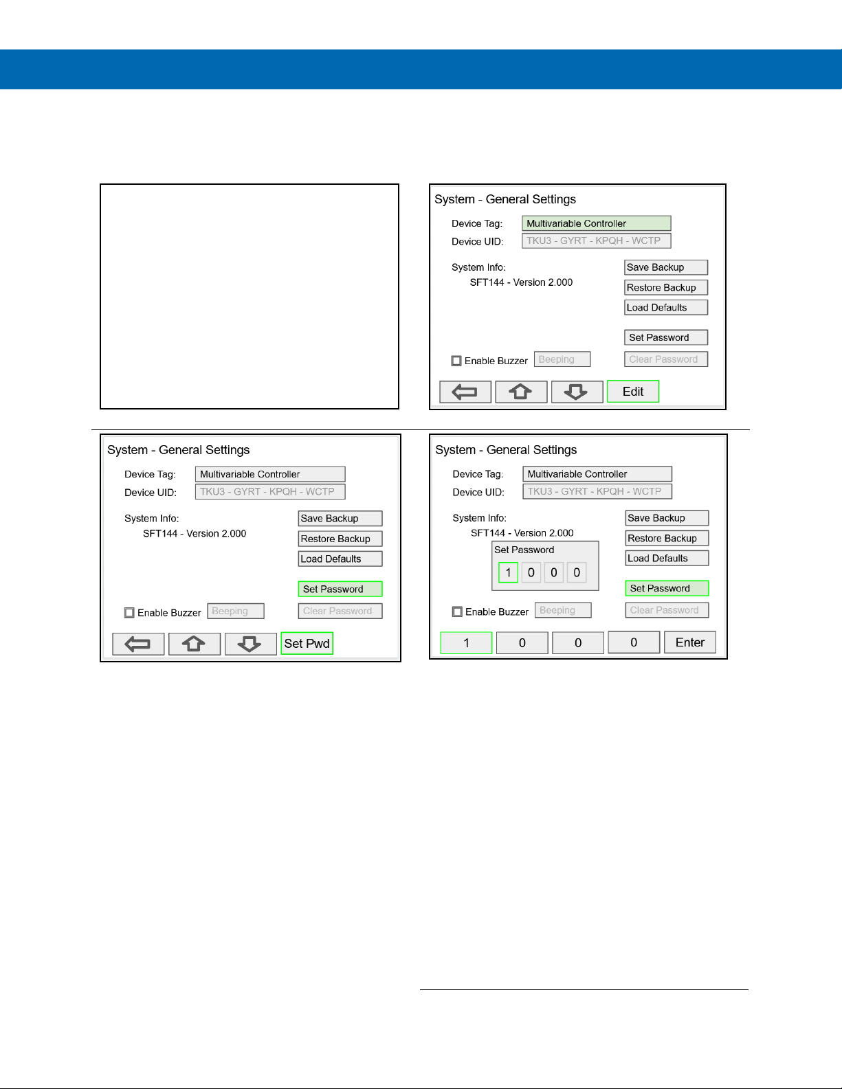
PD9000 ConsoliDator+ Multivariable Controller
password protected.
Instruction Manual
General Settings
The General Settings menu contains the settings listed
below.
Set Password
The user may enter a 4-digit password to protect the
system from unintentional changes.
• Device Tag: Edit the device tag (saved on Enter)
• Device UID: Device unique Id
• Enable Buzzer: Enable/disable internal buzzer*
• Save Backup: The current configuration is saved
• Restore Backup: Load backup configuration
• Load Defaults: Load factory defaults
• Set Password: Enter password to lock the system
• Clear Password: Remove the current password
*Buzzer Sound Options:
Beeping
Alarm
Solid
Warble
Carousel
Note: The internal buzzer is associated with the alarm's
Horn setting, which is available to drive any relay.
Password Protected Controller
The correct 4-digit password is required to make
changes to the system.
If the password is not correct after 3 attempts, the system
will not allow new tries until a timeout elapses. The
timeout will continue increasing for every 3 new
unsuccessful tries.
Remove Password Protection
To remove the password protection:
1. Enter the correct password
2. Go to the System menu – General Settings
3. Navigate to the Clear Password button
4. Press the Clr Pwd key
• The function keys and the digital inputs are not
52
Find Quality Products Online at: [email protected]
www.GlobalTestSupply.com
Page 53

PD9000 ConsoliDator+ Multivariable Controller
If an I/O card is removed permanently, pressing the
The settings provided in
menu are sufficient to
Instruction Manual
System Date & Time
The date & time of the system can be easily adjusted in
the System menu.
System Build
The Build menu provides the model number and it shows
the I/O cards installed with their location in the seven
available slots.
Modbus Settings & Passcode Protection
The Modbus settings must be configured to match the
settings of other devices on the bus. The Modbus Id
must be unique to each device on the bus.
Select Passcode and enter a Modbus passcode
between 0 and 9999 to prevent unauthorized writes to
the controller.
This is different than the main password used to protect
access to the Setup and View menus.
Ethernet Settings
The Ethernet menu provides basic information about the
Ethernet port and allows the user to program a static IP
Address, the port number, and the protocol to be used.
System
Rebuild key clears the information from the slot. This
should also be done if a different card is installed.
Replacing I/O Cards
In case that an I/O card fails, follow these steps:
Find Quality Products Online at: [email protected]
1) Save a backup copy of the configuration
2) Remove the defective card
3) Install the new card in the same slot where the
4) It is not necessary to click Rebuild
defective card was
www.GlobalTestSupply.com
establish Ethernet communications using TCP or UDP
protocols.
For more advanced setup, refer to the instructions
provided under Ethernet Port Setup on page 54.
Note:
If DHCP is selected, the device obtains a new IP
address automatically most of the time when the
power is cycled. This is not displayed on the
controller.
53
Page 54

PD9000 ConsoliDator+ Multivariable Controller
Ethernet Port Setup - Full
If more than one controller is connected to the
The Ethernet port option is fully configured using the
Lantronix DeviceInstaller software, available for download
from the Lantronix’s Website.
Follow these steps, after installation of the DeviceInstaller
software.
1. Connect an Ethernet cable to the Local Area Network
2. Launch the Lantronix DeviceInstaller; it will search for
XPort devices on the Local Area Network (LAN) and
display their status.
3. If no controller is found, click on Options, and select
the type of connection being used (e.g. Wi-Fi).
4.
network, determine which is the new controller by the
assigned IP address. If necessary, disconnect the new
controller and click Device – Search, take note of the
IP addresses listed. Next, connect the new controller
to the LAN and repeat the search; check the list to see
which the new IP address is.
Instruction Manual
• Consult with your IT department to configure
the Ethernet port and maintain network
security.
5. Double-click on the new device IP Address to be configured.
To communicate with a device connected over a LAN, you need the IP Address and the
Local TCP Port.
54
Find Quality Products Online at: [email protected]
www.GlobalTestSupply.com
Page 55

PD9000 ConsoliDator+ Multivariable Controller
6. Click on Configuration Records to find these settings, see the example above.
IP Address: 192.168.5.32; Local TCP Port: 10001 (0x2711)
Instruction Manual
7. Click on Web Configuration
8. Click on Network to assign a new IP Address
55
Find Quality Products Online at: [email protected]
www.GlobalTestSupply.com
Page 56
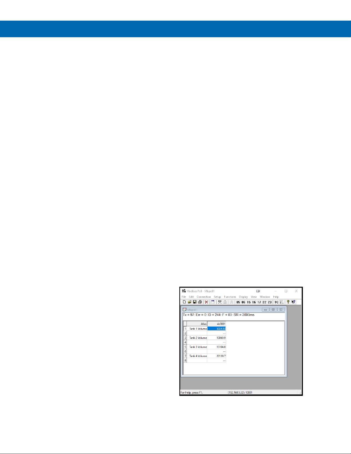
PD9000 ConsoliDator+ Multivariable Controller
Instruction Manual
9. Click on Channel 1 – Connection to select the protocol: TCP or UDP.
Note: For UDP protocol, select Datagram Type: 01
10. Under Endpoint Configuration, enter the Local Port to be used to access the controller
locally or from a remote location. This should be provided by your company’s IT department.
11. Click OK and then click Apply Settings for settings to be sent to the Ethernet device.
Test Ethernet Communication
Modbus Poll is an app that makes it easy to test your
Ethernet connection. Below are some screenshot
examples for Modbus TCP/IP connection.
56
Find Quality Products Online at: [email protected]
www.GlobalTestSupply.com
Page 57

PD9000 ConsoliDator+ Multivariable Controller
Custom Units
Custom units made be created either in the System
menu or when a parameter is created. Follow these
steps to create a custom unit:
• Go to the System menu – Custom Units
• Select New
• Enter a label for the unit (8 characters max)
• Select the unit type or None
• Select the base unit
• Enter the conversion factor
Delete Custom Units
Custom units can only be deleted if they are not been
used anywhere in the system.
To delete a custom unit, simply select the unit, navigate
to the Delete button, and press Ok to delete.
The Delete button is not available if the custom unit is
being used.
Instruction Manual
57
Find Quality Products Online at: [email protected]
www.GlobalTestSupply.com
Page 58
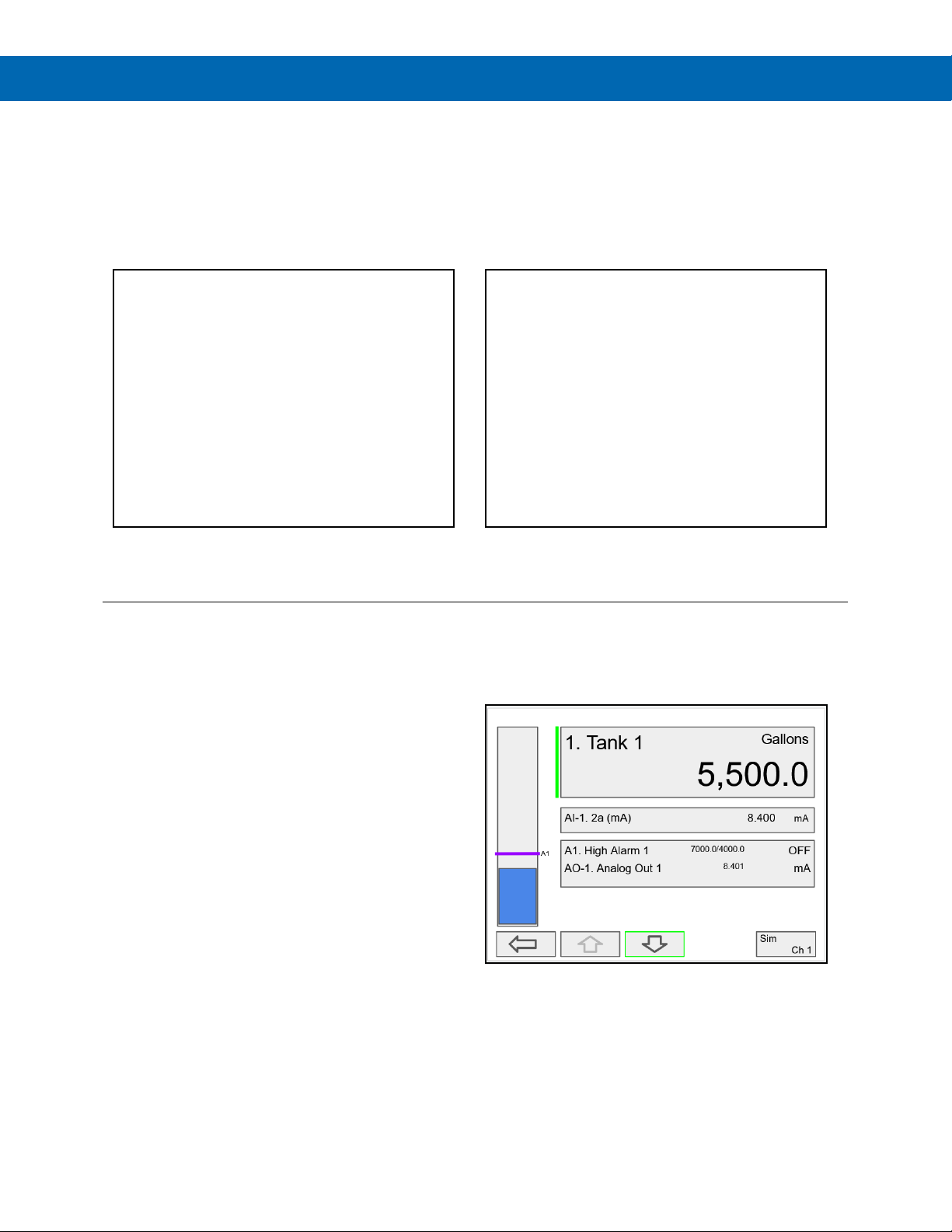
PD9000 ConsoliDator+ Multivariable Controller
View Channel Details
Instruction Manual
View Menu
The View menu is used to view individual channels, totals, timers, alarms, inputs, outputs,
and screens. For example, it provides the details for the current PV, what inputs are the
sources for the channel and what outputs are associated with the channel.
Accessing the individual parameters through the View menu also allows the simulation of
the various parameters for testing purposes as well as the manual control of the relays
and analog outputs.
Press the Right Arrow key to step into viewing
any channel.
Select any channel using the Up or Down Arrow keys
and Press the Right Arrow key again to step into
viewing the channel details.
Stepping into a channel allows the viewing of additional details for the inputs
and outputs associated with that channel. It is also possible to simulate the
selected parameter.
• Channel number and tag
• PV and units
• View the channel input source
• View alarms associated with channel
•
View analog outputs assigned to channel
•
Simulate the channel or analog input
•
Step into any associated parameter
Press the Down Arrow key to navigate to the
channel input source and then down again to view
alarms and analog outputs.
58
Find Quality Products Online at: [email protected]
www.GlobalTestSupply.com
Page 59
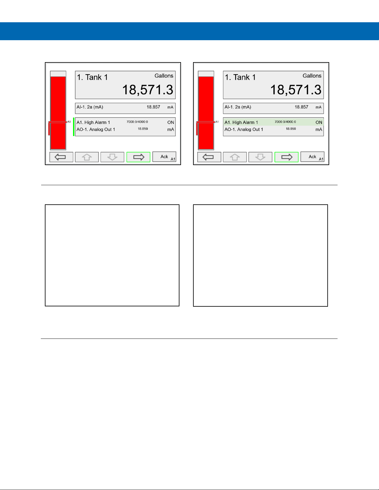
PD9000 ConsoliDator+ Multivariable Controller
View Alarm Details
View Associated Parameters
Instruction Manual
Press the Right Arrow key to select the alarm.
Press the 3-Bar key to access the available options.
Press the Right Arrow key again to view alarm’s details.
Alarm view options: acknowledge alarm, reset alarm,
change set/reset points, and simulate an alarm condition.
59
Find Quality Products Online at: [email protected]
www.GlobalTestSupply.com
Page 60

PD9000 ConsoliDator+ Multivariable Controller
View Totals
The View Totals menu displays the value of all the totals and allows resetting
each total individually.
• Total number and tag
• Accumulated total and units
• Reset total key
• View source for total
• View alarms associated with total
• View analog outputs assigned to total
Press Right Arrow key to step into details of the
selected total and view the source and associated
outputs.
Instruction Manual
Press the Right Arrow key to select Total 1.
Press the Enter key to enter a new total.
Find Quality Products Online at: [email protected]
www.GlobalTestSupply.com
Press the 3-Bar key to enter a new total, reset the total,
or simulate a value for the total.
Totals not associated with a rate channel have additional
features: Add to or remove from the total.
Using the numbers keypad, enter a new total and then
press the Enter key to save.
60
Page 61

PD9000 ConsoliDator+ Multivariable Controller
Totals Generated by Non-Rate Inputs
For totals generated using non-rate inputs; it is possible
to add or remove from the total using the 3-Bar key on
the View Total screen.
This type of total requires the use of an external trigger
such as a digital input, function key, or a Modbus signal.
For example, if the input to T1 is Ch 1, which is
displaying the volume in a container, as provided by the
weight being measured by a load cell with a 4-20 mA
output, which is the input to channel 1.
• Total 1 = 200,500 gallons
• Channel 1 = 100.0 gallons
• Press function key Add To (+ T1)
• 100 gallons is added to Total 1
The total in Tank 1 has been incremented by 100
gallons.
The Remove From feature can be used to decrement
the volume inside a storage tank.
Normally these operations are done automatically by
using a proximity switch or a limit switch to trigger the
Add To or Remove From features.
Instruction Manual
61
Find Quality Products Online at: [email protected]
www.GlobalTestSupply.com
Page 62

PD9000 ConsoliDator+ Multivariable Controller
Instruction Manual
View Timers
The View Timers menu displays the value of the existing timers.
Press the Right Arrow key to step into the details of the selected timer and view the associated inputs and outputs.
Press the Right Arrow key to step into viewing timer.
Press the Right Arrow key to select timer.
Press the Right Arrow key to view timer details.
Press the 3-Bar key to choose Timer Control, Reset,
Start, Stop, or Simulate.
Press the Reset key to reset the timer, select Timer
Control for additional functions. Use the Simulate
function to simulate the timer rising, falling, or jump to a
specific value using the keypad.
Find Quality Products Online at: [email protected]
www.GlobalTestSupply.com
Press the Timer Control key (shown in the timer details
screen) to access all timer control buttons.
62
Page 63

PD9000 ConsoliDator+ Multivariable Controller
View Alarms
Simulate Alarm Condition
Real
The View Alarms menu displays the status of all the alarms and the details for each alarm.
Under the alarm details view, it is possible to reset an acknowledged alarm,
change the set/reset points, or simulate an alarm condition.
• Alarm # and tag
• Set/Reset points
• Source for the alarm
• Outputs associated with the alarm
• Acknowledge the alarm
• Reset the alarm
• Simulate alarm condition
Press the Right Arrow key to view the alarm details.
Instruction Manual
Press the 3-Bar key to select Ack Alarm, Reset Alarm,
change Set Points, or Simulate Alarm condition.
Press the Simulate key to simulate an alarm condition.
Find Quality Products Online at: [email protected]
www.GlobalTestSupply.com
Press the Set Point key to change the Set Points. This
re-initializes the alarm to reflect the new set point.
Press the + key to turn on the alarm; note that alarm 13
and relay 1 also turned on. Press Ok key to maintain
simulation or press
63
to cancel simulation.
Page 64

PD9000 ConsoliDator+ Multivariable Controller
View Inputs
or use the
Ok
The View Inputs menu displays the values and status of all the inputs and
the details of the associated channels. Input simulation is also available in the input details.
• Input # and tag
• mA input value
• Pulse input frequency
• Digital input status
• Modbus input value
• Associated channel(s)
• Input simulation
Manual control and simulation states are not saved on
power cycle. On power up the controller initializes to the
actual process conditions.
Press the Right Arrow key to select the mA Input.
Instruction Manual
Press the Right Arrow key to view the mA Input details.
The above screen shows the Analog Input 2 details and
the associated channels.
Simulate mA Input
Use the + / - keys to ramp up and down
keypad to jump to any value within the range. Press the
key to maintain the input in simulation mode.
Find Quality Products Online at: [email protected]
www.GlobalTestSupply.com
All the parameters associated with the simulated input
follow the simulated value. Press the Real key to cancel
simulation and return to the actual sensor signal.
64
Page 65

PD9000 ConsoliDator+ Multivariable Controller
View Outputs
Manual Control of 4-20 mA Output
to control the analog output manually;
The View Outputs menu displays the values and status of all the outputs and
the details of the associated channels.
• Output # and tag
• mA output value
• Relay output status
• Digital output status
• Number of cycles & runtime
• Associated input
• Manual control of relays
• Manual control of 4-20 mA outputs
Manual control and simulation states are not saved on
power cycle. On power up the controller initializes to the
actual process conditions.
Press the Right Arrow key to select the mA Output.
Instruction Manual
Press the Right Arrow key to view the mA Output
details.
Select Manual
select Automatic to exit manual control.
Find Quality Products Online at: [email protected]
www.GlobalTestSupply.com
Press the 3-Bar key to access Analog Output controls.
Manual control, hold current value, return to automatic.
Use the keypad to enter a value for the analog output or
use the + / - keys to ramp up and down is small steps.
65
Page 66

PD9000 ConsoliDator+ Multivariable Controller
View Alert Messages
View Relays
The View Relays menu allows the user to view the
details for all the relays. The F4 key can be used to turn
on and off the selected relay (momentarily).
Press the Right Arrow key to view the relay details.
• Relay # and tag
• Status
• Runtime
• Number of Cycles
• Reset relay runtime & cycles count
• Parameters associated with the relay
• Other relays used in pump alternation
• Manual control of relays
Manual control and simulation states are not saved
on power cycle.
Instruction Manual
If Alerts are enabled for alarms, the Menu key displays a
flashing Alert! message on red background.
Simulated parameters and manual control outputs,
automatically generate alert messages displayed on a
yellow background.
Press the Manual OFF to turn off relay 1; Pump #1 will
go off and remain off until the relay 1 is put back in
automatic mode.
An Alert! message is displayed in place of the Menu key
anytime an item is in manual control or simulation mode.
The Alerts! Screen allows the user to acknowledge
alarms, return outputs to automatic mode, and navigate
to any of the listed items to view the details.
66
Find Quality Products Online at: [email protected]
www.GlobalTestSupply.com
Page 67

PD9000 ConsoliDator+ Multivariable Controller
View Modbus Outputs
View Digital Outputs
The View Digital Outputs screen displays the status of
the digital outputs and shows the association with the
parameters used to drive the outputs.
The View Modbus Outputs screen displays the Modbus
outputs set up by the user; it shows the register number
and the parameter used to generate each output.
Instruction Manual
Manual control and simulation states are not saved on
power cycle. On power up the controller initializes to the
actual process conditions.
67
Find Quality Products Online at: [email protected]
www.GlobalTestSupply.com
Page 68

PD9000 ConsoliDator+ Multivariable Controller
View Screens
With the View Screens menu, the user can go to any
available screen and view the details. The screens can
be scanned continuously or can be stopped to stay on a
selected screen at anytime.
Press the Right Arrow key to view details of the
the selected view screen.
Instruction Manual
Press the Scan key to have all available screens
continue to scan.
Find Quality Products Online at: [email protected]
www.GlobalTestSupply.com
Press the Stop key to have all available screens stop
scanning and stay on the current screen.
68
Page 69

PD9000 ConsoliDator+ Multivariable Controller
Individual Channel View
To view the details of any channel, press the Menu key and
bargraph.
Operation
Viewing Screens
The controller displays various screens with bargraphs,
numerical values, and relay status throughout
operation, according to the user-selected setup. There
are two basic modes of operation: Automatic scan or
manual scan. The controller initializes in automatic
scan mode. Press Stop key to stop the automatic scan
and use the Left or Right Arrow keys (Previous or
Next) to navigate through the various screens. Press
the Scan key to resume automatic scanning.
The bargraphs are optional, they are enabled or
disabled during Screens setup. The scaling of the
bargraph is done during the setup of each channel and
it can be different than the channel scaling values.
then press Right Arrow key to view the channels. Select the
channel of interest. Navigate through the different items
using the navigation keys. A green bar indicates the selected
item, press the Right Arrow key to step into and see more
details about the inputs and outputs related to the channel in
view.
If applicable, alarms may be acknowledged, and totals may
be reset from these screens. Simulation and manual control
are also available on the View screens.
Low & High Alarm Indication
The alarm set points are indicated by a line at the
corresponding value on the bargraph. Color selection is
done in the Setup – Alarm menu or in the System – Display
menu.
Active High Alarm: Indicated by horizontal and vertical
lines. The bottom of the vertical line is the reset point of the
high alarm. The high alarm is indicated on the left side of the
bargraph.
Active Low Alarm: Indicated by horizontal and vertical
lines. The top of the vertical line is the reset point of the low
alarm. The low alarm is indicated on the right side of the
Instruction Manual
Alarm set points are indicated by horizontal lines.
Low alarm indication
Find Quality Products Online at: [email protected]
www.GlobalTestSupply.com
High alarm indication
69
Page 70
PD9000 ConsoliDator+ Multivariable Controller
Multicolor Bargraph Indication
The bargraph may be configured to show different colors
< 25
Green
N/A
N/A
depending on the value of the process variable. The
following example illustrates the use of colors:
Process
Variable %
> 25 Yellow 25.0 25.0
> 50 Amber 50.0 50.0
> 75 Red 75.0 75.0
Bargraph
Color
Set Pt Reset Pt
Instruction Manual
Color changes above the set point for each alarm
The bargraph shows green below the the first set point
The bargraph changes to orange above set point 2
The bargraph changes to yellow above set point 1
The bargraph changes to red above set point 3.
The panel for the value can also be configured to change
colors at the specified levels.
70
Find Quality Products Online at: [email protected]
www.GlobalTestSupply.com
Page 71
PD9000 ConsoliDator+ Multivariable Controller
Command
Name
Description
Reg. Number
Reg. Address
Description
Data Type
Function Codes
R/W
40011
10
Channel (6) Value
Float
03, 04
R
Instruction Manual
Modbus® RTU Serial Communication
The controller is equipped with serial communication capability as a standard feature. Baud Rate, Parity, Slave ID
(Address) and Transmit Delay are entered in the System menu, which appears in the main Setup menu. The baud
rate and parity selected must match the settings for all other devices on the network. The Slave ID must be unique,
so it will not interfere with other devices. The controller supports the following Modbus functions:
01 Read Coils (0x) Read coil value
03 Read Holding Register (4x) Read multiple bytes from holding registers.
04 Read Input Register (3x) Read multiple bytes from input registers.
05 Write Single Coil (Bit) Set single coil value control
15 Write Multiple Coils (Bits) Set multiple coil value control
06 Write Single Register Set single value into specified holding register.
16 Write Multiple Registers Set multiple values into specified holding registers.
The multi-channel controller can also work as a “Modbus Display/Controller” by writing the desired value to the selected Modbus
input (MB-1 to MB-199). The Modbus input can be used the same way a 4-20 mA input is used; it can be brought into a channel to
be displayed and generate alarms to control relays, generate 4-20 mA outputs, and Modbus outputs (MO-1 to MO-64).
Modbus Register Tables
Table 1. Default Register Numbers / Addresses
40001 0 Channel (1) Value Float 03, 04 R
40003 2 Channel (2) Value Float 03, 04 R
40005 4 Channel (3) Value Float 03, 04 R
40007 6 Channel (4) Value Float 03, 04 R
40009 8 Channel (5) Value Float 03, 04 R
40013 12 Channel (7) Value Float 03, 04 R
40015 14 Channel (8) Value Float 03, 04 R
40017 16 Total (1) Value Float 03, 04 R
40019 18 Total (2) Value Float 03, 04 R
40021 20 Total (3) Value Float 03, 04 R
40023 22 Total (4) Value Float 03, 04 R
40025 24 Timer (1) Value Float 03, 04 R
40027 26 Timer (2) Value Float 03, 04 R
40029 28 Timer (3) Value Float 03, 04 R
40031 30 Timer (4) Value Float 03, 04 R
40033 32 Alarm (1) Status* Short 03, 04 R
40034 33 Alarm (2) Status* Short 03, 04 R
40035 34 Alarm (3) Status* Short 03, 04 R
40036 35 Alarm (4) Status* Short 03, 04 R
40037 36 Alarm (5) Status* Short 03, 04 R
40038 37 Alarm (6) Status* Short 03, 04 R
40039 38 Alarm (7) Status* Short 03, 04 R
40040 39 Alarm (8) Status* Short 03, 04 R
*Alarm Status: 0: Off, 1: On, 2: On & Acknowledged
The table above contains some predefined registers and data types used.
The following table contains the definitions of all accessible registers with their corresponding data type.
71
Find Quality Products Online at: [email protected]
www.GlobalTestSupply.com
Page 72
PD9000 ConsoliDator+ Multivariable Controller
RTC Date & Time
Program is executed when
Table 2. Device Tag, Date & Time, Info
Reg. Number Reg. Address Description Data Type Function Codes R/W Comments
40041 40056 40-55 Device Tag
40061 60 Year Short 03, 04 R 20 = 2020
40062 61 Month Short 03, 04 R
40063 62 Day Short 03, 04 R
40064 63 Hour Short 03, 04 R
40065 64 Minute Short 03, 04 R
40066 65 Second Short 03, 04 R
40073 72 SFT No. Short 03, 04 R
40074 73 SFT Version Short 03, 04 R
40081 80 Program Id Short 06, 16
40082 40099
81 - 98
Program Parameters
(x18)
String
(32 char) 03, 04 R
W
W
Various 06, 16
Instruction Manual
Null terminating string
Write 00 for the last char
Program Id is written.
Program parameters may
be written either before or
with the Program Id.
See
Table 4. for details.
72
Find Quality Products Online at: [email protected]
www.GlobalTestSupply.com
Page 73

PD9000 ConsoliDator+ Multivariable Controller
Reg. Number
Reg. Address
Channel (N = 1 ... 99)
Data Type
Bits
Function
R/W
Reg. Address Examples
Total (N = 1 ... 32)
Timer (N = 1 ... 32)
Modbus Output (N = 1 … 64)
44201 + 2(N - 1)
4200 + 2(N - 1)
Modbus Output (N) Value
Long
32
03, 04
R
MO-1 = 4202
Modbus Input (N = 1 … 199)
Instruction Manual
PV’s Register Numbers & Addresses
The PV’s register numbers and register addresses are calculated based on the formulas provided below. The values
are available in various data types. Examples of register addresses (base 0) are provided on the right column.
Register numbers refer to PLC Addresses (base 1). Function Code 03 Read Holding Registers (4x) are shown on this
table and used throughout the system; other functions are also supported as indicated in the Function column.
The Modbus input registers can be configured under the Setup – Inputs – Modbus menu and the Modbus output
registers can be mapped under the Setup – Outputs – Modbus menu; this allows assigning any parameter to the
Modbus output registers and selecting the data type for input and output registers.
Table 3. PV’s Register Numbers & Register Addresses
00101 + (N - 1) 100 + (N - 1) Channel (N) Value Bit 1 01, 02 R Ch1 = 100
40101 + (N - 1) 100 + (N - 1) Channel (N) Value Short 16 03, 04 R Ch1 = 100
40201 + 2(N - 1) 200 + 2(N - 1) Channel (N) Value Long 32 03, 04 R Ch2 = 202
40401 + 2(N - 1) 400 + 2(N - 1) Channel (N) Value Float 32 03, 04 R Ch3 = 404
40601 + 4(N - 1) 600 + 4(N - 1) Channel (N) Value Double 64 03, 04 R Ch4 = 612
41001 + 4(N - 1) 1000 + 4(N - 1) Channel (N) Value Long Long 64 03, 04 R Ch99 = 1392
42101 + (N - 1) 2100 + (N - 1) Total (N) Value Short 16 03, 04 R Total 1 = 2100
42201 + 2(N - 1) 2200 + 2(N - 1) Total (N) Value Long 32 03, 04 R Total 1 = 2202
42301 + 2(N - 1) 2300 + 2(N - 1) Total (N) Value Float 32 03, 04 R Total 1 = 2302
42401 + 4(N - 1) 2400 + 4(N - 1) Total (N) Value Double 64 03, 04 R Total 1 = 2404
42601 + 4(N - 1) 2600 + 4(N - 1) Total (N) Value Long Long 64 03, 04 R Total 32 = 2724
43101 + (N - 1) 3100 + (N - 1) Timer (N) Value (sec) Short 16 03, 04 R Timer 1 = 3100
43201 + 2(N - 1) 3200 + 2(N - 1) Timer (N) Value (sec) Long 32 03, 04 R Timer 1 = 3202
43301 + 2(N - 1) 3300 + 2(N - 1) Timer (N) Value (sec) Float 32 03, 04 R Timer 1 = 3302
43401 + 4(N - 1) 3400 + 4(N - 1) Timer (N) Value (sec) Double 64 03, 04 R Timer 32 = 3524
Alarm (N = 1 ... 64)
43601 + (N - 1) 3600 + (N - 1) Alarm (N) Status Short 03, 04 R 0: Off, 1: On, 2: On & Ack
04101 + (N - 1) 4100 + (N - 1) Modbus Output (N) Value Bit (0 or 1) 1 01, 02 R MO-1 = 4100
44101 + (N - 1) 4100 + (N - 1) Modbus Output (N) Value Short 16 03, 04 R MO-1 = 4100
44401 + 2(N - 1) 4400 + 2(N - 1) Modbus Output (N) Value Float 32 03, 04 R MO-1 = 4402
44601 + 4(N - 1) 4600 + 4(N - 1) Modbus Output (N) Value Double 64 03, 04 R MO-1 = 4604
45001 + 4(N - 1) 5000 + 4(N - 1) Modbus Output (N) Value Long Long 64 03, 04 R MO-64 = 5252
06101 + (N - 1) 6100 + (N - 1) Modbus Input (N) Value Bit (0 or 1) 1
46101 + (N - 1) 6100 + (N - 1) Modbus Input (N) Value Short 16
46301 + 2(N - 1) 6300 + 2(N - 1) Modbus Input (N) Value Long 32 03, 04, 16 R/W MB-1 = 6302
46701 + 2(N - 1) 6700 + 2(N - 1) Modbus Input (N) Value Float 32 03, 04, 16 R/W MB-1 = 6702
47101 + 4(N - 1) 7100 + 4(N - 1) Modbus Input (N) Value Double 64 03, 04, 16 R/W MB-1 = 7104
47901 + 4(N - 1) 7900 + 4(N - 1) Modbus Input (N) Value Long Long 64 03, 04, 16 R/W MB-199 = 8692
64
01, 02,
05, 15
03, 04,
06, 16
R/W MB-1 = 6100
R/W MB-1 = 6100
73
Find Quality Products Online at: [email protected]
www.GlobalTestSupply.com
Page 74
PD9000 ConsoliDator+ Multivariable Controller
Reg.
Number
Reg.
Address
Data
Type
Program
Code
40081
80
Program Id
Program is executed when
Program Id is written.
40099
81 - 98
Parameters (x8)
Program parameters may be
Program Code.
40081
80
Unlock Modbus
Passcode
Short
06, 16
W 1 Locks again after 30 seconds.
40082
81
Modbus
Passcode
Short
06, 16
W
Cleared upon execution. Must be
re-written with each Unlock.
40081
80
Set RTC
Date & Time
Short
06, 16
W 6
40082
81
Year
Short
06, 16
W 0..99
40083
82
Month
Short
06, 16
W 1..12
40084
83
Day
Short
06, 16
W 1..31
40085
84
Hour
Short
06, 16
W
0..23
Second to zero.
40086
85
Minute
Short
06, 16
W
0..59
zero
40087
86
Second
Short
06, 16
W 0..59
40081
80
Channel - Get
Tag
Short
06, 16
W
11 40082
81
Channel (N)
Short
06, 16
W
40083 40090
82 - 89
Tag
String
(16 char)
03, 04
R Null terminated string.
40081
80
Reset Channel
Short
06, 16
W
12 40082
81
Channel (N)
Short
06, 16
W
Program Code with only single
parameters.
40083
82
Thru Channel (N)
Short
06, 16
W 0 to ignore
40081
80
Set Channel
Short
06, 16
W
13
Tare, Capture, Switch
40082
81
Channel (N)
Short
06, 16
W
Program Code with only single
parameters.
40083
82
Thru Channel (N)
Short
06, 16
W 0 to ignore
40081
80
Total - Get Tag
Short
06, 16
W
27 40082
81
Total (N)
Short
06, 16
W
40083 40090
82 - 89
Tag
String
(16 char)
03, 04
R Null terminated string.
Instruction Manual
Modbus Write Protection
The Modbus write passcode protection can be enabled in the System – Modbus menu. This protection prevents
writing to the registers, unless the unlock code 1 is sent to register 81 followed by the passcode sent to register 82.
The protection is automatically restored after 30 seconds of Modbus – write inactivity. See page 53 for details.
Table 4. Program Parameters for Special Functions
40082 -
Description
Program
Function R/W
Comments
written either before or with the
Program Code plus parameters
ending at Hour will set Minute and
Program Code plus parameters
ending at Minute will set Second to
parameter will ignore remaining
parameter will ignore remaining
Find Quality Products Online at: [email protected]
www.GlobalTestSupply.com
74
Page 75
PD9000 ConsoliDator+ Multivariable Controller
Reg.
Number
Reg.
Address
Data
Type
Program
Code
40081
80
Reset Total
Short
06, 16
W
28 40082
81
Total (N)
Short
06, 16
W
Program Code with only single
parameters.
40083
82
Thru Total (N)
Short
06, 16
W 0 to ignore
40081
80
Timer - Get Tag
Short
06, 16
W
41 40082
81
Timer (N)
Short
06, 16
W
40083 40090
82 - 89
Tag
String
(16 char)
03, 04
R Null terminated string.
40081
80
Timer
Short
06, 16
W
42 40082
81
Timer (N) - Reset
Short
06, 16
W
0 to not Reset
(N) will Reset without Start or Stop.
40083
82
Timer (N) - Start
Short
06, 16
W
0 to not Start
ignore Stop.
40084
83
Timer (N) - Stop
Short
06, 16
W 0 to not Stop
40085
84
Thru Timer (N) Reset
Short
06, 16
W 0 to ignore
40086
85
Thru Timer (N) Start
Short
06, 16
W 0 to ignore
40087
86
Thru Timer (N) Stop
Short
06, 16
W 0 to ignore
40081
80
Alarm - Get Tag
Short
06, 16
W
55 40082
81
Alarm (N)
Short
06, 16
W
40083 40090
82 - 89
Tag
String
(16 char)
03, 04
R Null terminated string.
40081
80
Reset Alarm
Short
06, 16
W
56 40082
81
Alarm (N)
Short
06, 16
W
Program Code with only single
parameters.
40083
82
Thru Alarm (N)
Short
06, 16
W 0 to ignore
40081
80
Ack Alarm
Short
06, 16
W
57 40082
81
Alarm (N)
Short
06, 16
W
Program Code with only single
parameters.
40083
82
Thru Alarm (N)
Short
06, 16
W 0 to ignore
40081
80
Alarm - Start
Short
06, 16
W
58
Interval alarms
40082
81
Alarm (N)
Short
06, 16
W
Program Code with only single
parameters.
40083
82
Thru Alarm (N)
Short
06, 16
W 0 to ignore
Description
Function R/W
Instruction Manual
Comments
parameter will ignore remaining
Program Code with parameters will
ignore remaining parameters.
Program Code with single Timer
Program Code with two Timer (N)
registers will Reset and Start; and
parameter will ignore remaining
parameter will ignore remaining
parameter will ignore remaining
Find Quality Products Online at: [email protected]
www.GlobalTestSupply.com
75
Page 76

PD9000 ConsoliDator+ Multivariable Controller
Reg.
Number
Reg.
Address
Data
Type
Program
Code
40081
80
Alarm - Stop
Short
06, 16
W
59
Interval alarms
40082
81
Alarm (N)
Short
06, 16
W
Program Code with only single
parameters.
40083
82
Thru Alarm (N)
Short
06, 16
W 0 to ignore
40081
80
Alarm - Restart
Short
06, 16
W
60
Interval alarms
40082
81
Alarm (N)
Short
06, 16
W
Program Code with only single
parameters.
40083
82
Thru Alarm (N)
Short
06, 16
W 0 to ignore
40081
80
Horn - Silence
Short
06, 16
W
73
Horn Off until new trigger.
40081
80
Horn - Snooze
Short
06, 16
W
74
Horn Off until new trigger, or until
Seconds.
40082
81
Seconds
Short
06, 16
W
40081
80
Horn - Test
Short
06, 16
W
75
Horn Off until Seconds.
40082
81
Seconds
Short
06, 16
W
40081
80
Relay - Get Tag
Short
06, 16
W
82 40082
81
Relay (N)
Short
06, 16
W
40083 40090
82 - 89
Tag
String
(16 char)
03, 04
R Null terminated string.
40081
80
Relay - Reset Info
Short
06, 16
W
83 40082
81
Relay (N)
Short
06, 16
W
Program Code with only single
parameters.
40083
82
Thru Relay (N)
Short
06, 16
W 0 to ignore
40081
80
Relay - Automatic
Short
06, 16
W
84 40082
81
Relay (N)
Short
06, 16
W
Program Code with only single
parameters.
40083
82
Thru Relay (N)
Short
06, 16
W 0 to ignore
40081
80
Relay - Manual
ON
Short
06, 16
W
85 40082
81
Relay (N)
Short
06, 16
W
Program Code with only single
parameters.
40083
82
Thru Relay (N)
Short
06, 16
W 0 to ignore
40081
80
Relay - Manual
OFF
Short
06, 16
W
86 40082
81
Relay (N)
Short
06, 16
W
Program Code with only single
parameters.
40083
82
Thru Relay (N)
Short
06, 16
W 0 to ignore
Description
Function R/W
Instruction Manual
Comments
parameter will ignore remaining
parameter will ignore remaining
parameter will ignore remaining
parameter will ignore remaining
parameter will ignore remaining
parameter will ignore remaining
Find Quality Products Online at: [email protected]
www.GlobalTestSupply.com
76
Page 77
PD9000 ConsoliDator+ Multivariable Controller
Reg.
Number
Reg.
Address
Data
Type
Program
Code
40081
80
Relay - Manual
Hold
Short
06, 16
W
87 40082
81
Relay (N)
Short
06, 16
W
Program Code with only single
parameters.
40083
82
Thru Relay (N)
Short
06, 16
W 0 to ignore
40081
80
mA Out - Get Tag
Short
06, 16
W
92 40082
81
mA Out (N)
Short
06, 16
W
40083 40090
82 - 89
Tag
String
(16 char)
03, 04
R Null terminated string.
40081
80
mA Out Automatic
Short
06, 16
W
93 40082
81
mA Out (N)
Short
06, 16
W
Program Code with only single
parameters.
40083
82
Thru mA Out (N)
Short
06, 16
W 0 to ignore
40081
80
mA Out - Manual
Short
06, 16
W
94 40082
81
mA Out (N)
Short
06, 16
W
40083 40084
value (N)
float
06, 16
W
40081
80
mA Out - Manual
Short
06, 16
W
95 40082
81
mA Out (N)
Short
06, 16
W
40083
82
value x 100 (N)
Short
06, 16
W
For 4.00 mA, write 400. For 16.5
mA, write 1650.
40081
80
mA Out - Manual
Hold
Short
06, 16
W
96 40082
81
mA Out (N)
Short
06, 16
W
Program Code with only single
parameters.
40083
82
Thru mA Out (N)
Short
06, 16
W 0 to ignore
Description
Function R/W
Instruction Manual
Comments
parameter will ignore remaining
parameter will ignore remaining
parameter will ignore remaining
Find Quality Products Online at: [email protected]
www.GlobalTestSupply.com
77
Page 78
PD9000 ConsoliDator+ Multivariable Controller
40081
80
Relay - Automatic
Short
06, 16
W
84 40082
81
Relay (N)
Short
06, 16
W
Program Code with only single
parameters.
40083
82
Thru Relay (N)
Short
06, 16
W 0 to ignore
40081
80
Relay - Manual
ON
Short
06, 16
W
85 40082
81
Relay (N)
Short
06, 16
W
Program Code with only single
parameters.
40083
82
Thru Relay (N)
Short
06, 16
W 0 to ignore
40081
80
Relay - Manual
OFF
Short
06, 16
W
86 40082
81
Relay (N)
Short
06, 16
W
Program Code with only single
parameters.
40083
82
Thru Relay (N)
Short
06, 16
W 0 to ignore
1) To manually turn on relay 1 write:
Instruction Manual
Relay Control Using Modbus
To control the relays via Modbus, use the Write Single Coil command [command code 05] or Write Multiple Coils
[command code 15] and send either the “ON” or “OFF” to the Modbus input associated with the target relay.
Setup Example #1
Follow this example to set up Modbus Input to control a relay and configure the system to display messages related
to the status of the device being controlled, in this case a pump.
Setup – MB-1.
1. Tag: Modbus Input 1
2. Type: Bit – Logic (Reg. No. 06101 or Reg. Address 06100)
3. Units: Logic = PUMP ON / PUMP OFF
4. Break: Default = OFF
Setup – RY-1.
1. Tag: Relay 1
2. Input: MB-1. Modbus Input 1
Setup – Create Screen
1. Title: Pumps
2. MB-1. Modbus Input 1
3. RY-1. Relay 1
4. F3: Assign to Force On RY-1
5. F4: Assign to Force Off RY-1
Operation: Write “1” to Reg. 06101 to turn relay 1 On; write “0” to turn relay 1 Off.
Setup Example #2
Follow this example to control the relays directly from Modbus using special program functions. You can control one
or all relays with one command.
parameter will ignore remaining
parameter will ignore remaining
parameter will ignore remaining
a. Reg. 40081: 85
b. Reg. 40082: 1
c. Reg. 40083: 0 (last relay, if more than one)
2) To manually turn off relay 1 write:
a. Reg. 40081: 86
b. Reg. 40082: 1
c. Reg. 40083: 0 (last relay, if more than one)
3) To return relays to normal operation write commands
for automatic control.
a. Reg. 40081: 84
Find Quality Products Online at: [email protected]
www.GlobalTestSupply.com
78
Page 79
PD9000 ConsoliDator+ Multivariable Controller
Symptom
Check/Action
No display or only backlight is
1. Ambient temperature is below -40°C and affects
Check earth ground continuity.
Check the 4-20 mA input; if less than the break value
changed in the Input menu.
Display response seems slower
than normal
Ambient temperature is too cold: Consider installing a
heater with the instrument.
1. Check signal source stability
3. Decrease the display refresh rate (increase time)
1. Cycle the power or
cards are tightly fixed in place.
does not respond at all
Settings reprogrammed, but
previously programmed
2. Check Setup menu alarm set and reset points.
Check register number or register address being used
(e.g. 6700)
Controller does not communicate
with another device.
Check baud rates and parity settings. Make sure all
serial devices have matching parameters.
Other symptoms not described
above
System Password:
Troubleshooting Tips
Instruction Manual
visible, but outputs still function
normally.
“BREAK” is displayed
Display reading is unstable, it
fluctuates too much
mA input not responding to signal
changes (value frozen)
Display locks up or the instrument
instrument behavior remains as
Relay and status do not respond
to signal
Writing to Modbus Input register
failed
LCD visibility.
2. Grounding is inadequate or not connected.
(e.g. 0.01 mA), it displays BREAK. This can be
2. Increase filter value
2. Go to setup mA input and disable input channel,
then enable the input channel
3. Check that back cover is fully seated, and all I/O
Cycle the power to reboot the microprocessor.
Cycle the power to reboot the microprocessor.
1. Check if relays are in manual control mode.
1. If using PLC address (Base 1) use register
number (e.g. 46701)
2. If using Base 0 address, use register address
Model:
Serial Number:
Call Technical Support for assistance.
Find Quality Products Online at: [email protected]
www.GlobalTestSupply.com
79
 Loading...