

Page 1

ProtEX-MAX PD8-6210 Explosion-Proof Batch Controller
Instruction Manual
PRECISION DIGITAL CORPORATION
233 South Street • Hopkinton MA 01748 USA
Tel (800) 343-1001 • Fax (508) 655-8990
www.predig.com
• Fully-Approved Explosion-Proof Batch Controllers
• 0-20 mA, 4-20 mA, 0-5 V, 1-5 V, and ±10 V Inputs with ±0.03% Accuracy
• Dual-Line 6-Digit Display, 0.6" (15 mm) & 0.46" (12 mm)
• SafeTouch Through-Glass Button Programming
• Display Mountable at 0°, 90°, 180°, & 270°
• Isolated 24 VDC @ 25 mA Transmitter Power Supply
• Easy Field Scaling in Engineering Units without Applying an Input
• 4 Relays with Interlocking Capability + Isolated 4-20 mA Output
• Free PC-Based, On-Board, MeterView Pro USB Programming Software
• SunBright Display Standard Feature; Great for Outdoor Applications
• Start / Pause / Stop, Change Batch with Front Panel Buttons
• Display Batch Total, Rate, Grand Total, Count or Preset
• Single or Multi-Stage Batch Control (Up to 4 Relays)
• Front Panel or Remote Total Reset
• Automatic Overrun Correction
• Automatic or Manual Batch Control
• Low or High Flow Alarms while Batching
• 32-Point Linearization, Square Root Extraction and Programmable Exponent Function
• Operating Temperature Range: -40 to 60°C (-40 to 140°F)
• FM Approved as Explosion-Proof / Dust-Ignition-Proof / Flame-Proof
• CSA Certified as Explosion-Proof / Dust-Ignition-Proof / Flame-Proof
• ATEX and IECEx Certified as Flame-Proof
• Input Power Options: 85-265 VAC / 90-265 VDC or 12-24 VDC / 12-24 VAC
• Programmable Display, Function Keys & Digital Inputs
• Flanges for Wall or Pipe Mounting
• Explosion-Proof, IP68, NEMA 4X Die-Cast Aluminum Enclosure
• On-Board RS-485 Serial Communications
• Modbus RTU Communication Protocol Standard
• Password Protection
• Four 3/4" NPT Threaded Conduit Openings (Two Plugs Installed)
• 3-Year Warranty
MeterView Pro
USB Install
Page 2
2
Page 3
ProtEX-MAX PD8-6210 Explosion-Proof Analog Input Batch Controller
Instruction Manual
3
Disclaimer
The information contained in this document is
subject to change without notice. Precision Digital
makes no representations or warranties with
respect to the contents hereof and specifically
disclaims any implied warranties of
merchantability or fitness for a particular purpose.
See Warranty Information and Terms &
Conditions on www.predig.com for complete
details.
• Read complete instructions prior to installation
and operation of the controller.
• Risk of electric shock or personal injury.
• This product is not recommended for life support
applications or applications where malfunctioning
could result in personal injury or property loss.
Anyone using this product for such applications
does so at his/her own risk. Precision Digital
Corporation shall not be held liable for damages
resulting from such improper use.
• Failure to follow installation guidelines could
result in death or serious injury. Make sure only
qualified personnel perform the installation.
• Never remove the controller cover in explosive
environments when the circuit is live.
• Cover must be fully engaged to meet
explosion-proof/dust-ignition-proof/flame-proof
requirements.
WARNING
Cancer and Reproductive Harm - www.P65Warnings.ca.gov
Limited Warranty
Precision Digital Corporation warrants this
product against defects in material or
workmanship for the specified period under
“Specifications” from the date of shipment from
the factory. Precision Digital’s liability under this
limited warranty shall not exceed the purchase
value, repair, or replacement of the defective unit.
See Warranty Information and Terms & Conditions
on www.predig.com for complete details.
Registered Trademarks
All trademarks mentioned in this document are
the property of their respective owners.
© 2022 Precision Digital Corporation.
All rights reserved.
FREE MeterView Pro
Programming Software
The controller can be powered from the USB connection. When
using the USB connection, DO NOT apply AC or DC power to
the controller.
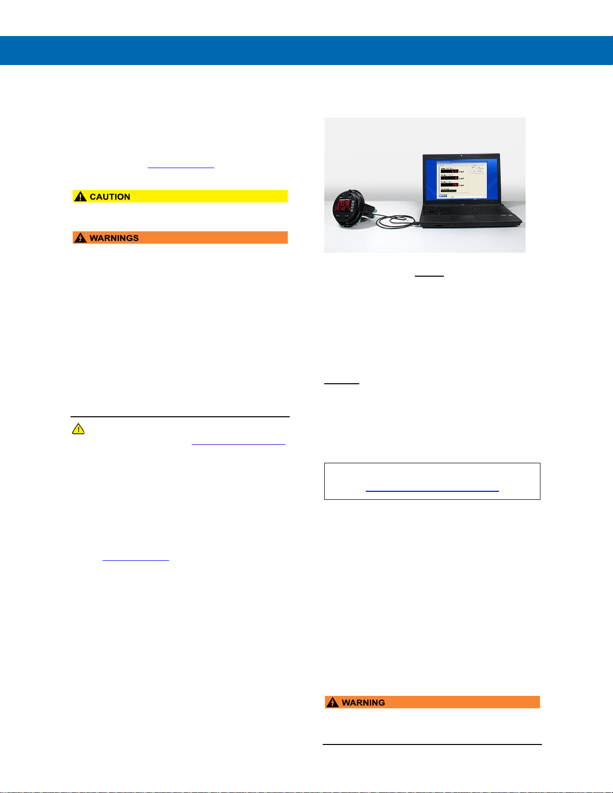
The easiest and quickest way to program your
ProtEX-MAX batch controller is to use the FREE
MeterView Pro programming software. This software
is loaded into the controller and connects and installs
directly to your PC with a USB cable. We recommend
that the first thing you do after taking the controller out
of the box is connect the ProtEX-MAX to your PC with
the provided USB cable – do not use a different cable.
DO NOT apply AC or DC power to the controller while
your PC is connected to the controller as it will disrupt
the USB connection. You don’t even have to apply an
input signal.
MeterView Pro programming software is intuitive, and
most customers can get their controller programmed
as they like without even looking in the manual.
Watch MeterView Pro Software Video at
www.predig.com/meterviewpro
In addition to programming, the software may be used
to perform many useful tasks:
• Start, Pause, Stop the batch
• Change preset & pre-close settings
• Reset total & grand total
• Test the relays functionality
• Monitor the batch process
• Datalogging using your PC
• Generate & save program files for later use
Once your controller is programmed the way you want
it, you can wire it up for your application per the
instructions in this manual and install it. If you find that
you need to make adjustments to the programming
after the controller is installed, you can use the
programming buttons and the instructions in this
manual to do so.
• When using the USB connection, the controller
should only be connected to a computer when
both devices are in a non-hazardous area.
Page 4

ProtEX-MAX PD8-6210 Explosion-Proof Analog Input Batch Controller
Instruction Manual
4
Table of Contents
Introduction ......................................................................................................... 7
Ordering Information .......................................................................................... 7
Key Features ....................................................................................................... 9
Specifications ................................................................................................... 16
General ................................................................................................ .......... 16
Batch Controller Rate/Totalizer Display ..................................................... 17
Process Inputs ............................................................................................. 18
Relays ............................................................................................................ 19
USB Connection ........................................................................................... 19
Isolated 4-20 mA Transmitter Output ......................................................... 19
RS-485 Serial Communications .................................................................. 19
Modbus® RTU Serial Communications ....................................................... 19
Digital Input (F4) ........................................................................................... 20
Digital Inputs & Outputs .............................................................................. 20
MeterView Pro Software .............................................................................. 20
Compliance Information................................................................................... 21
Electromagnetic Compatibility .................................................................... 21
Product Ratings and Approvals .................................................................. 21
EU Declaration of Conformity .......................................................................... 22
Safety Information ............................................................................................ 22
Installation......................................................................................................... 22
Unpacking ..................................................................................................... 22
Mounting ....................................................................................................... 23
Installation Overview ................................................................................... 25
MeterView Pro Software .............................................................................. 25
Transmitter Supply Voltage Selection (P+, P-) .......................................... 26
Connections ................................................................................................. 26
Required & Factory Wired Connection .................................................. 26
PROVU Electronics Module Layout ............................................................. 27
USB Connection ........................................................................................ 27
Power Connections .................................................................................... 28
Signal Connections .................................................................................... 29
Relay Connections ..................................................................................... 29
Interlock Relay Feature .............................................................................. 29
Switching Inductive Loads.......................................................................... 30
RS-485 Connections .................................................................................. 30
RS-485 Multi-Drop Connection .................................................................. 30
F4 Digital Input Connections ...................................................................... 31
4-20 mA Output Connections ..................................................................... 31
Analog Output Transmitter Power Supply .................................................. 32
Remote Programming ................................................................................ 32
Setup and Programming .................................................................................. 33
Overview ................................ ....................................................................... 33
LED Status Indicators .................................................................................. 33
Programming Buttons ................................................................................. 34
SafeTouch Buttons ...................................................................................... 34
Display Functions and Messages ............................................................... 35
Main Menu ..................................................................................................... 37
Setting Numeric Values ................................................................ ............... 37
Setting Up the Batch Controller (setup) ..................................................... 37
Setting the Input Signal (Input) ................................................................. 38
Setting the Totalizer & Batch Control Features (total) ............................. 38
Setting the Input Units or Custom Tags (units) ........................................ 38
Setting the Decimal Point (dEc pt) ........................................................... 39
Programming the Batch Controller (prog).................................................. 39
Setting the Display Parameter & Intensity (dsplay) .................................. 42
Display Intensity (d-Inty).......................................................................... 42
Page 5

ProtEX-MAX PD8-6210 Explosion-Proof Analog Input Batch Controller
Instruction Manual
5
Setting the Relay Operation (relay) ........................................................... 43
Relay Assignment (Assign) ....................................................................... 44
Setting the Relay Action ............................................................................. 45
Setting Batch Control Relays ..................................................................... 45
Programming Alarm Set and Reset Points................................................. 45
Setting Fail-Safe Operation ........................................................................ 45
Programming Time Delay .......................................................................... 45
Relay Action for Loss of 4-20 mA Input (Loop Break) ................................ 45
Automatic Batch Control Operation ............................................................ 46
Relay and Alarm Operation Diagrams ........................................................ 47
High Alarm Operation (Set > Reset) .............................................................. 47
Low Alarm Operation (Set < Reset) ........................................................... 47
High Alarm with Fail-Safe Operation (Set > Reset) .................................... 47
Low Alarm with Fail-Safe Operation (Set < Reset)..................................... 47
Time Delay Operation ................................................................................ 48
Total Relay Sampling Operation ................................................................ 48
Relay Operation Details ............................................................................... 49
Overview .................................................................................................... 49
Relays Initialization .................................................................................... 49
Fail-Safe Operation .................................................................................... 49
Front Panel LEDs ....................................................................................... 49
Automatic Reset (Auto) ............................................................................. 49
Pump Alternation Control ........................................................................... 49
Sample Relay Operation ............................................................................ 50
Setting Up the Interlock Relay (Force On) Feature .................................... 50
Scaling the 4-20 mA Analog Output (Aout)................................................ 51
Reset Menu (reset) ...................................................................................... 51
Manual Control Menu (Contrl) ................................................................... 51
Setting Up the Password (pass) .................................................................. 52
Protecting or Locking the Controller ........................................................... 52
Grand Total Reset Password & Non-Resettable Total ............................... 52
Making Changes to a Password Protected Controller ................................ 52
Disabling Password Protection .................................................................. 52
Controller Operation ........................................................................................ 53
Button Operation .......................................................................................... 53
SafeTouch Buttons ...................................................................................... 53
Default Batch Control Operation................................................................. 53
Batch Control Operation Example .............................................................. 54
Manual Batch Control .................................................................................. 55
Automatic Batch Control ............................................................................. 56
Setup with MeterView Pro ........................................................................... 58
Operate with MeterView Pro ........................................................................ 58
Advanced Setup & Programming .................................................................... 59
Advanced Features Menu ............................................................................ 59
Advanced Features Menu & Display Messages ......................................... 59
Function Keys Operation ........................................................................... 60
Digital Inputs Operation ............................................................................. 60
Advanced Setup and Calibration ................................................................ 61
Maximum/Minimum Readings .................................................................... 61
Noise Filter (filter) ................................................................................. 61
Noise Filter Bypass (bypass) ..................................................................... 61
Rounding Feature (round) ......................................................................... 61
Modbus RTU Serial Communications (serial) ......................................... 61
Select Menu (SElEct) ................................................................................ 62
Programmable Function Keys User Menu (user) ...................................... 64
Internal Source Calibration (ICAL) ............................................................. 65
Troubleshooting ............................................................................................... 66
Diagnostics Menu (diag) ........................................................................... 66
Testing the Display LEDs ........................................................................... 66
Determining Software Version ................................................................... 66
Reset Controller to Factory Defaults .......................................................... 66
Factory Defaults & User Settings ............................................................... 67
Troubleshooting Tips ................................................................................... 69
Page 6

ProtEX-MAX PD8-6210 Explosion-Proof Analog Input Batch Controller
Instruction Manual
6
Table of Figures
Figure 1. Enclosure Dimensions – Front View ............................................... 23
Figure 2. Enclosure Dimensions – Side Cross Section View ....................... 23
Figure 3. Transmitter Supply Voltage Selection ............................................ 26
Figure 4. Integrated PROVU Required Connections ....................................... 26
Figure 5. PROVU Electronics Module Layout .................................................. 27
Figure 6. USB Connection ............................................................................... 27
Figure 11. Power Connections ........................................................................ 28
Figure 12. Transmitter Powered by Internal Supply ...................................... 29
Figure 13. Transmitter Powered by Ext. Supply or Self-Powered ................ 29
Figure 14. Voltage Input Connections ............................................................ 29
Figure 15. Relay Connections ......................................................................... 29
Figure 28. Interlock Connection ...................................................................... 29
Figure 16. AC and DC Loads Protection ......................................................... 30
Figure 17. Low Voltage DC Loads Protection ................................................ 30
Figure 15. RS-485 Diagnostic LEDs ................................................................ 30
Figure 22. Three-Wire RS-485 Connection ..................................................... 30
Figure 23. Digital Input and Output Connections .......................................... 31
Figure 24. F4 Digital Input Connections ......................................................... 31
Figure 25. 4-20 mA Output Connections ........................................................ 31
Figure 26. Analog Output Supply Powering Other Devices .......................... 32
Page 7
ProtEX-MAX PD8-6210 Explosion-Proof Analog Input Batch Controller
Instruction Manual
7
Introduction
The ProtEX-MAX PD8-6210 is an explosion-proof
analog input batch controller ideal for simplifying
independent batch control operations where local
control is preferred to expensive and expansive plant
operation systems. The controller features a dual-line
display, with a main display 0.60" (15 mm) high, and a
second display of 0.46" (12 mm) high superluminous
LED digits, which can be read in any lighting
condition, including direct sunlight. The controller is
housed in a die-cast aluminum, field-mountable,
NEMA 4X/IP68 rated enclosure for convenient indoor
and outdoor installation.
The controller comes programmed for easy start,
pause, stop, and batch size (preset) changes. The
second display can be programmed to display rate,
grand total, batch count, or preset by cycling the Stop
(F3) button. Digital inputs come standard.
Single and multi-stage batching is possible with four
(4) on-board relays. Each batch control relay may
have a unique preclose amount when used for
multi-stage batching. Manual start batching is default,
but automatic batching with a restart after a
programmed time delay from the completion of the
last batch is also possible.
Overrun correction adjusts the closing of the batch
control relays to adjust for inaccuracies from batch to
batch. This increases accuracy over time as systems
wear out. The overrun correction feature is capable of
compensating for inaccuracies of up to 1% of the
programmed preset value.
The controller accepts current and voltage signals
(e.g. 4-20 mA, 0-10 V).
The PD8-6210 batch controller comes with four SPDT
relays, a 4-20 mA output, two 24 VDC power
supplies, five digital inputs and four digital outputs,
and RS-485 serial communications, making it an
excellent addition to any system.
Ordering Information
85-265 VAC Models
Model
Standard Features
PD8-6210-6H7
4 relays, 4-20 mA output,
5 Digital Inputs, 4 Digital Outputs,
RS-485 Communications
12-24 VDC Models
Model
Standard Features
PD8-6210-7H7
4 relays, 4-20 mA output,
5 Digital Inputs, 4 Digital Outputs,
RS-485 Communications
Accessories
Model
Description
PDA0001
3/4" M-NPT to F-M20 Reducer
PDA0002
3/4" M-NPT to 1/2" F-NPT Reducer
PDAPLUG75
3/4" Metal Conduit/Stopping Plug
PDA-SSTAG
Custom Stainless Steel Tag (see
website for convenient ordering form)
PDA6848
2" U-Bolt Kit Zinc Plated Steel
PDA6848-SS
2" U-Bolt Kit Stainless Steel
PDA7485-I
RS-232 to RS-485 isolated converter
PDA8485-I
USB to RS-485 isolated converter
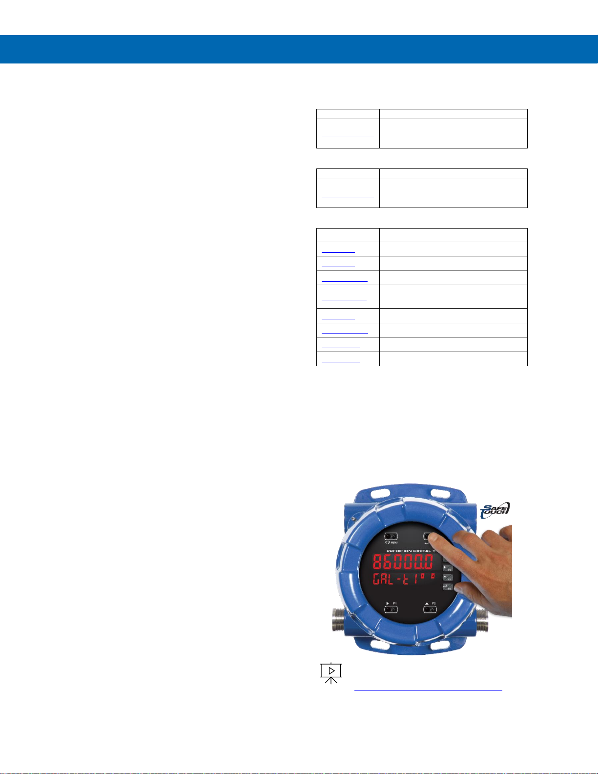
SafeTouch Buttons
To make it possible to program and operate the
ProtEX-MAX in a hazardous area, the programming
buttons that are located behind the glass window can
be operated without removing the cover by using the
SafeTouch through-glass buttons. The operator puts
their finger on the glass over the button and the
button is actuated.
To learn more about SafeTouch buttons,
see this video:
predig.com/videos/Safetouch_Buttons
Page 8
ProtEX-MAX PD8-6210 Explosion-Proof Analog Input Batch Controller
Instruction Manual
8
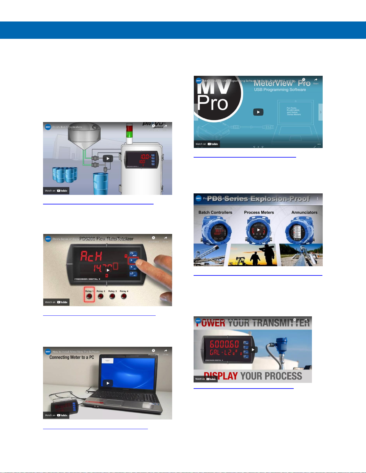
Helpful Videos
There are several videos that will help you get a
better understating of the features and functionality of
the ProtEX-MAX products. Since the ProtEX-MAX
meters have the same general features and
functionality of the ProVu meters, appropriate videos
for the ProVu controller are also included.
PROVU Batch Controllers
These provide simple batch control with features like
preclose relays and automatic overrun correction.
https://www.predig.com/videos/KN6Y6R0I1OE
PROVU Function Keys Tutorial
Learn how the PROVU’s function keys increase the
utility of the PROVU.
https://www.predig.com/videos/WMBYKlavW-Q
Connect a PROVU to a PC Using
MeterView Pro
Learn how easy it is to use MeterView Pro software.
https://www.predig.com/videos/PC_Connect
MeterView Pro USB Programming
Software
Learn how easy it is to program a PROVU PD6000
process meter.
https://www.predig.com/videos/MVPro_SW
ProtEX-MAX Explosion-Proof Family
The ProtEX-MAX Series has been designed to offer
the functions and features of any ProVu in a great
looking explosion-proof housing.
https://www.predig.com/videos/ProtEXMAX_Overview
4-20 mA Connections
This Tech Tips video shows how to make connections
to power the transmitter with the ProVu’s
(ProtEX-MAX’s) 24 VDC power supply.
predig.com/videos/4-20_mA_Connections
Page 9
ProtEX-MAX PD8-6210 Explosion-Proof Analog Input Batch Controller
Instruction Manual
9
Key Features
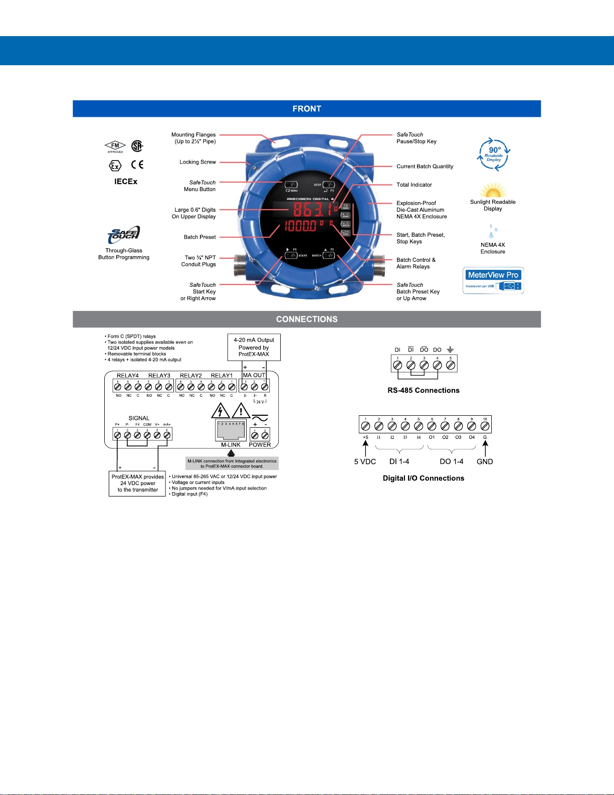
Connections for PD8-6210-6H7 & PD8-6210-7H7
The Only Explosion-Proof Batch Controller You Will Ever Need
The ProtEX-MAX PD8-6210 explosion-proof batch
controllers are specifically designed for displaying
flow rate and total from flowmeters with analog
outputs.
The first thing you notice about the PD8-6210 is its
modern looking, rugged, die-cast aluminum housing
with convenient mounting flanges. Housed inside this
enclosure is a dual-line, 6-digit display that is usually
setup to show the current batch quantity and the
batch preset on the two lines. START, BATCH, and
STOP buttons (which can be operated remotely or
without removing the cover) come setup by default for
batch control operation. The START button starts the
batch. The BATCH button shows the preset value.
The STOP button pauses or stops the batch.
The PD8-6210 is approved as a complete product by
FM and CSA and also carries ATEX and IECEx
certification. One of the more convenient features of
the PD8-6210 is its through-glass SafeTouch buttons
which allow the controller to be operated without
removing its cover. Just put your finger on the glass
over the button to actuate it. The PD8-6210 can also
provide 5, 10, or 24 VDC to power the flowmeter.
A ProtEX-MAX batch controller can be programmed
for a wide variety of applications. Setup is easy for
single or multi-stage batching. Automatic overrun
correction keeps the batch size accurate, even over
time. The PD8-6210 can display the number of
batches that have been run and the total amount of
product that has been batched. These features and
capabilities can easily be programmed without
removing the cover using SafeTouch buttons in a
hazardous area or with free MeterView Pro PC-based
software in a safe area.
Page 10
ProtEX-MAX PD8-6210 Explosion-Proof Analog Input Batch Controller
Instruction Manual
10
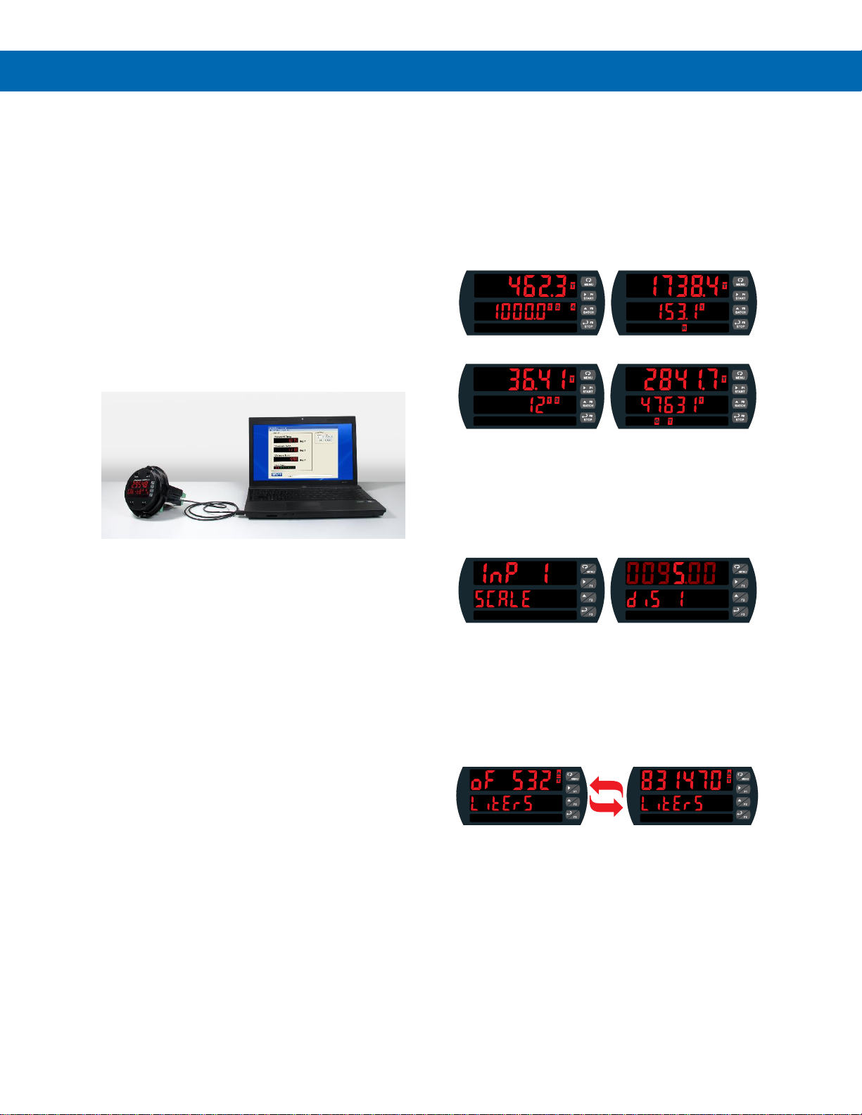
Easy Programming Methods
The ProtEX-MAX can be programmed in a hazardous
area with the through-glass SafeTouch buttons
without removing the cover, in a safe area with the
front panel push buttons with the cover removed, or in
a safe area with free, PC-based MeterView Pro
software. MeterView Pro is resident on the
ProtEX-MAX and is accessed by a provided USB
cable, so it is by far the easiest way to program the
ProtEX-MAX. The ProtEX-MAX can be calibrated
either by applying a known signal or scaled by
entering a desired value with the front panel buttons
or MeterView Pro software. Most customers will use
the scaling method because it is simpler and does not
require a calibrated signal source. Selecting the input
to be current or voltage is done with the front panel
buttons or MeterView Pro software. Once programming
is completed it can be locked with a password.
The ProtEX-MAX comes preloaded with free
MeterView Pro programming software that connects
and installs directly to your PC with a standard USB
cable, also provided free with each instrument. This
eliminates the need to insert CDs, install drivers, or
download software from the internet. When you
connect your ProtEX-MAX to your PC, MeterView Pro
is downloaded to your PC, the software automatically
selects the model you are programming, and you’re
ready to start programming immediately. Further
simplifying the programming process, the
ProtEX-MAX can be powered from the USB port, so
no need to apply external power while programming
your controller. In addition to programming, the
software will also allow you to monitor, and datalog a
ProtEX-MAX using your PC. You can also generate
and save programming files for later use.
Advanced Display Features
Display What You Want
The most common setup for these batch controllers is
to display the batch total on the main display and batch
preset on the second display. This allows the user to
monitor the batch as it progresses and compare it to
the total batch size. Other possible setups include
displaying the batch total and flow rate, batch total
and batch count, and batch total and grand total.
Batch Total & Preset Batch Total & Rate
Batch Total Batch Total
& Batch Count & Grand Total
Easy to Use
The user-friendly dual-line display makes the PROVU
easy to set up & program. No jumpers to set for input
selection. All setup & programming are done via the
front panel.
Input Setup Display Setup
Totalizer Overflow Displays Total to 9 Digits
These flow rate/totalizers can display up to nine digits of
total flow with the total overflow feature. In the diagram
below, the flow totalizer is displaying 532,831,470 by
toggling between a display of “oF 532” and “831470”.
Notice the (T with arrow ▲ symbol) is lit up indicating
the display is in overflow mode.
Super-Bright Display
The ProtEX-MAX comes standard with a super-bright
display, with LEDs that are visible even in direct sunlight.
The display also has up to eight levels of adjustable
intensity for optimum visibility in any lighting condition.
Rounding for Even Steadier Display
The rounding feature is used to give the user a
steadier display with fluctuating signals. It causes the
display to round to the nearest value according to the
rounding value selected (1, 2, 5, 10, 20, 50, or 100).
For example, with a rounding value of 10, and an
input of 12346, the display would indicate 12350.
Page 11
ProtEX-MAX PD8-6210 Explosion-Proof Analog Input Batch Controller
Instruction Manual
11
Batch Controller Capabilities
A ProtEX-MAX batch controller can be programmed
for a wide variety of single or multi-stage batching
applications and set up to run in either manual or
automatic operation. Batch size can be displayed on
the controller and is easily programmed and changed
if needed. The controller can even display the number
of batches that have been run. Automatic overrun
correction keeps the batch size accurate, even over
time and with system wear. The controller can display
the rate with a time base of seconds, minutes, hours
or days. The user can program a conversion factor,
configure a non-resettable grand total, and configure
password protection.
Manual or Automatic Batch Control
Batches may be started manually with the START
front panel button, or with a remote digital input
trigger. Batches may also be programmed to start
automatically after a 0 to 999.9 second delay after the
end of the last completed batch. A manually stopped
batch will only restart after the START button is
pressed or digital input triggered.
Automatic Overrun Correction
The ProtEX-MAX batch controller will correct for batch
overrun or shortages automatically. By tracking the
amount the batch was off by, the controller will
automatically adjust the batch by modifying the batch
relay deactivation time.
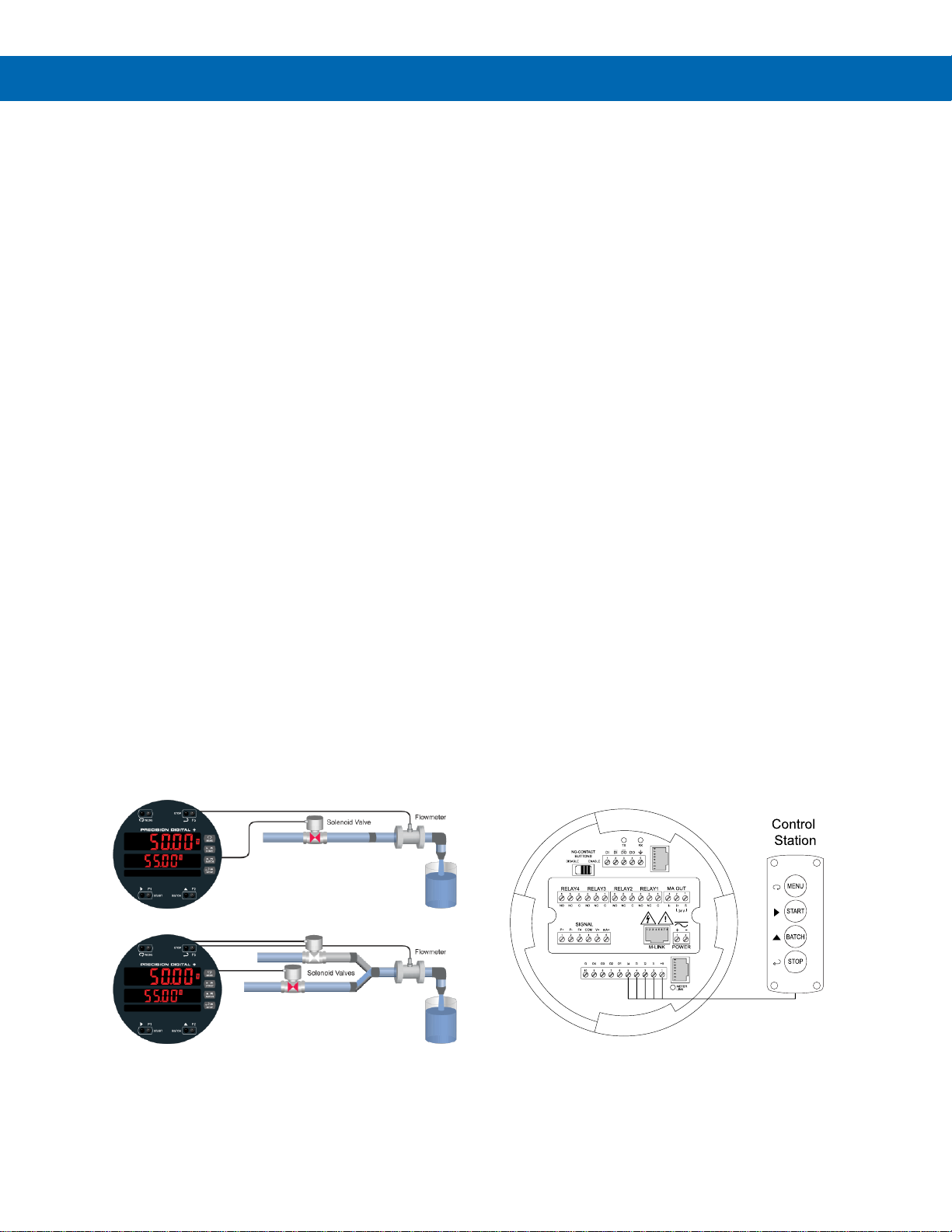
Single and Multi-Stage Batching
The ProtEX-MAX can be used as a single or
multi-stage batch controller. Relays assigned to the
total act as batch control relays, with additional relays
beyond the first including a preclose value. The
preclose deactivates the relay before the batch is
finished, to allow slower fill rates and a more accurate
batch finish. Each additional stage batching relay has
an individually programmable preclose amount.
Single Stage Batch Control
Multi-Stage Batch Control
Quick Preset Changes
The front panel BATCH key is configured by default to
access the preset menu. The preset may be changed
quickly and easily between batches without the need
to enter setup menus.
Non-Resettable Grand Total
The user can set up the grand total to be non-resettable
by entering a specific password. Once this is done,
the grand total can never be reset.
Total Conversion Factor
The user can enter a conversion factor that allows the
controller to display total in different units than the
rate. For instance, an operator could measure flow
rate in gallons per minute and grand total in millions of
gallons.
Grand Total & Rate Alarms
The ProtEX-MAX’s four internal relays can be set up
to alarm when the grand total reaches a user-defined
set point or when the rate is above or below a certain
value. Rate alarms are only activated when the
batching process is running. A variety of reset modes
are available and the user can also program time
delays and fail-safe operation.
F4 Digital Input
The digital input can be used for a variety of functions
such as starting or stopping a batch, resetting the total,
or resetting an alarm relay. This is ideal for installations
where the controller is inaccessible behind a cover, or
where an additional function key is needed for
customized operation.
Remote Operation of Controller
There are four digital inputs that can be programmed
to mimic the MENU, START, BATCH, and STOP
buttons that could be controlled by a control station*
suitable for location in a hazardous area.
* Control station must be approved for hazardous
locations
Page 12
ProtEX-MAX PD8-6210 Explosion-Proof Analog Input Batch Controller
Instruction Manual
12
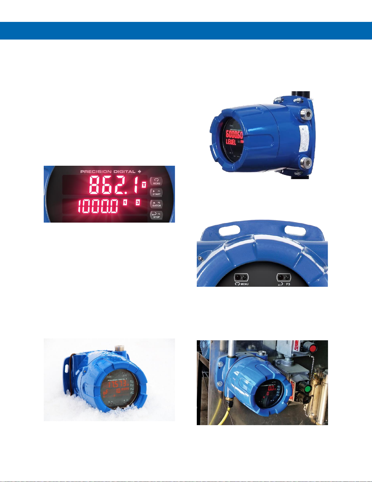
Physical Features
The ProtEX-MAX is designed for ease-of-use in safe
and hazardous applications. The ProtEX-MAX is
housed in a rugged NEMA 4X explosion-proof
enclosure, can operate over a wide temperature
range, includes removable screw terminal connectors,
has worldwide approvals for use in hazardous areas,
and features through-glass buttons for easy controller
operation without the need to remove the cover.
All of these features are backed by a 3-year warranty.
Super-Bright LED Display
The ProtEX-MAX features a dual-line 6-digit display
with super-bright LEDs, our brightest ever. These
allow the display to be read in any lighting condition,
even in direct sunlight.
SafeTouch Through-Glass Buttons
The ProtEX-MAX is equipped with four sensors that
operate as through-glass buttons so that it can be
programmed and operated without removing the
cover (and exposing the electronics) in a hazardous
area. These buttons can be disabled for security by
selecting the DISABLE setting on the NO-CONTACT
BUTTONS switch located on the back of the
electronics module, inside the enclosure.
Rugged, Heavy-Duty Enclosure
The ProtEX-MAX is housed in a rugged NEMA 4X, 7,
& 9, IP68 die-cast aluminum enclosure, designed to
withstand harsh environments in safe and hazardous
areas across a wide temperature range.
Wide Viewing Angle
Customers can’t always look at the display from
straight on, so the window and display module have
been optimized to provide a wide viewing angle of
approximately ± 40°; nearly twice that of the
competition.
Built-In Mounting Flanges
The ProtEX-MAX is equipped with four slotted flanges
for wall mounting or NPS 1½" to 2½" or DN 40 to
65 mm pipe mounting.
Flexible Mounting & Wiring
The ProtEX-MAX features four ¾" NPT threaded
conduit openings so that wiring can be routed to the
most convenient conduit connection(s). Two ¾" NPT
metal conduit plugs with 12 mm hex key fitting come
installed.
Page 13
ProtEX-MAX PD8-6210 Explosion-Proof Analog Input Batch Controller
Instruction Manual
13
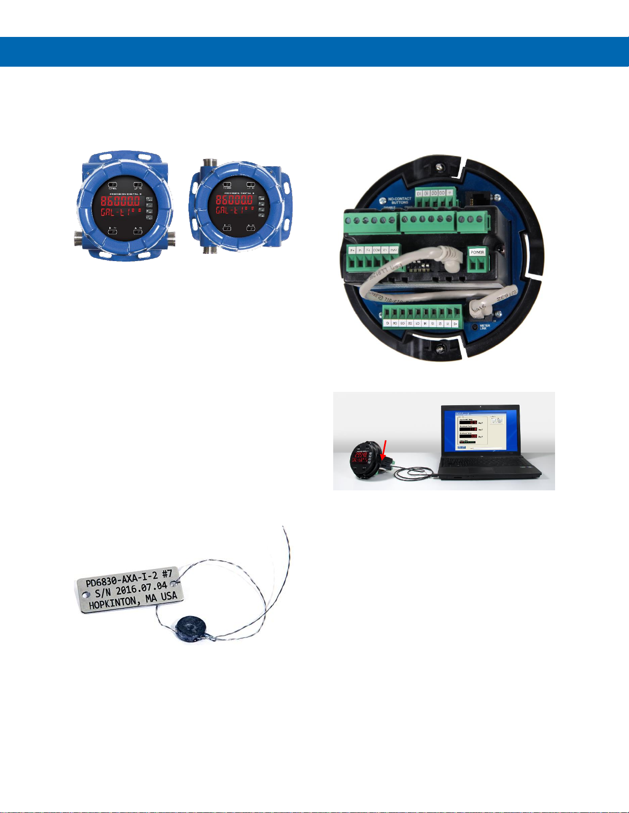
Rotatable Display
The ProtEX-MAX rotatable display, along with four
available conduit connections, provide for numerous
installation options. The display can be rotated in 90°
increments. Rotate it 90° for horizontal mounting.
Vertical Mounting Horizontal Mounting
Perfect & Secure Fit Every Time
The internal cast rails ensure the ProtEX-MAX
assembles together perfectly, quickly and securely;
and everything lines up for optimal viewing every
time. There are no standoffs to worry about breaking
or getting out of alignment. Two spring-loaded,
self-retaining, thumbscrews make the assembly a
snap, while pressing the display as close to the glass
as possible to improve wide angle viewing.
Stainless Steel Tags
PDA-SSTAG is a laser etched stainless steel tag
accessory for any of your Precision Digital controllers.
The tag features custom text for equipment
identification, instruction, or whatever else is needed
in your facility. Each tag comes with a stainless steel
wire and lead seal for easy mounting wherever you
need it.
Removable Screw Terminals
Industrial applications require screw terminal
connections for easy field wiring and the ProtEX-MAX
goes one step further in convenience by making them
removable also.
USB Port MeterView Pro
Hazardous Area Approvals
The ProtEX-MAX's approvals allow it to be used in
hazardous areas around the world. These include: FM
Approved as Explosion-Proof / Dust-Ignition-Proof /
Flame-Proof, CSA Certified as Explosion-Proof /
Dust-Ignition-Proof, and ATEX and IECEx Certified as
Flame-Proof.
Wide Operating Temperature Range
The ProtEX-MAX can operate from -40 to 60°C
(-40 to 140°F) meaning it can be installed in a wide
variety of indoor and outdoor industrial applications.
And over this range, the ProtEX-MAX will drift no
more than 0.005% of calibrated span/°C max from
0 to 65°C ambient and 0.01% of calibrated span/°C
max from -40 to 0°C ambient.
USB cable conveniently
plugs into side of
ProtEX-MAX controller
Page 14
ProtEX-MAX PD8-6210 Explosion-Proof Analog Input Batch Controller
Instruction Manual
14
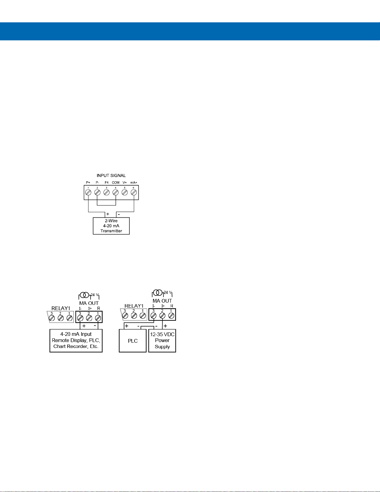
Transmitter Power Supplies
Controller Powers Transmitter
One of the most useful standard features of the
PD8-6210 is its built-in isolated, 24 V @ 25 mA power
supply to power the transmitter. This feature saves
money by eliminating an external power supply and
also simplifies wiring by reducing the number of
devices in the loop. It can be configured for 5, 10, or
24 V (default) by means of a simple internal jumper.
This power supply is even available on controllers that
are powered from DC power (24 V @ 25 mA). To use
an external power supply instead of the internal power
supply, simply make connections to different terminals
on the ProtEX-MAX.
The following diagram illustrates how to wire the
ProtEX-MAX so it will power the transmitter:
Controller Powers 4-20 mA Output
Not only can the ProtEX-MAX power the 4-20 mA
input signal, but an additional power supply of
24 V @ 25 mA is provided with the 4-20 mA output
option to power the 4-20 mA output.
Fuse Prevents Current Overload
Another very useful aspect of the ProtEX-MAX is that
the current input is protected against current overload
by a resettable fuse. The fuse limits the current to a
safe level when it detects a fault condition, and
automatically resets itself when the fault condition is
removed.
Page 15
ProtEX-MAX PD8-6210 Explosion-Proof Analog Input Batch Controller
Instruction Manual
15
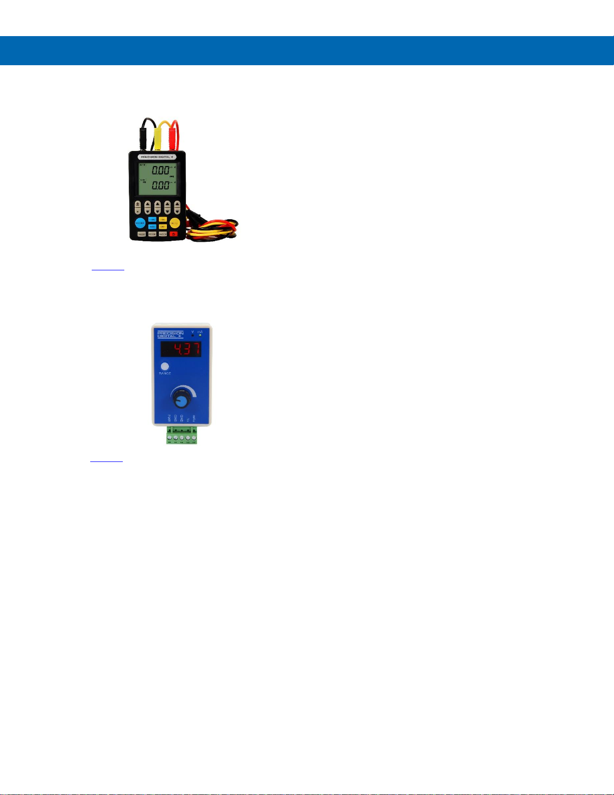
Useful Tools
PD9501 Multi-Function Calibrator
This PD9501 Multi-Function Calibrator has a variety
of signal measurement and output functions, including
voltage, current, thermocouple, and RTD.
PD9502 Low-Cost Signal Generator
The PD9502 is a low-cost, compact, simple to use
4-20 mA or 0-10 VDC signal generator. It can easily
be set for 0-20 mA, 4-20 mA, 0-10 V or 2-10 V ranges.
Signal adjustment is made with a one-turn knob. A
15-27 VDC wall plug is provided with the instrument.
Optional USB power bank is available.
Page 16

ProtEX-MAX PD8-6210 Explosion-Proof Analog Input Batch Controller
Instruction Manual
16
Specifications
Except where noted all specifications apply to
operation at +25°C.
General
Display
Display Line 1: 0.60" (15 mm) high,
red LEDs
Display Line 2: 0.46" (12 mm) high,
red LEDs
6 digits each (-99999 to 999999),
with lead zero blanking
Display
Intensity
Eight user selectable intensity levels.
Default is six.
Display
Update Rate
5/second (200 ms)
LED Status
Indicators
See LED Status Indicators on page 33 for
details
Overrange
Display flashes 999999
Underrange
Display flashes -99999
Default
Display
Assignment
Line 1 displays batch total. Line 2 displays
batch preset, and can be switched to show
grand total, or batch count with the STOP
key.
Custom
Display
Assignment
Display lines 1 and 2 may be assigned to
rate, total, grand total, batch count, preset,
set points, units (second display only),
alternating R & T, R & GT, preset & rate,
max & min, or a Modbus display register.
Any rate/total/grand total display may be
programmed to alternate with a custom unit
or tag.
Alternating
Display
Displays alternate every 10 seconds when
display is selected, or the batch is paused.
Programming
Methods
Four SafeTouch through-glass buttons
when cover is installed. Mechanical buttons
can be used with the cover removed. Free
PC-based USB MeterView Pro
programming software.
Noise Filter
Programmable from 2 to 199
(0 will disable filter)
Filter Bypass
Programmable from 0.1 to 99.9% of
calibrated span
Recalibration
All ranges are calibrated at the factory.
Recalibration is recommended at least
every 12 months.
Max/Min
Display
Max/min readings reached by the process
are stored until reset by the user or until
power to the controller is cycled.
Rounding
Select 1, 2, 5, 10, 20, 50, or 100
(e.g. rounding = 10, value = 123.45,
display = 123.50)
Password
Three programmable passwords restrict
modification of programmed settings and
two prevent resetting the totals.
Pass 1: Allows use of function keys and
digital inputs
Pass 2: Allows use of function keys, digital
inputs and editing set/reset points
Pass 3: Restricts all programming, function
keys, and digital inputs.
Total Password: Prevents resetting the total
manually
Gtotal Password: Prevents resetting the
grand total manually
Non-Volatile
Memory
Total and Grand Total values, and all
programmed settings are stored in nonvolatile memory for a minimum of ten years
if power is lost.
Power
Options
85-265 VAC 50/60 Hz; 90-265 VDC, 20 W max;
12-24 VDC, 12-24 VAC, 15 W max.
Powered over USB for configuration only.
Fuse
Required external fuse: UL Recognized,
5 A max, slow blow; up to 6 controllers may
share one 5 A fuse
Normal Mode
Rejection
Greater than 60 dB at 50/60 Hz
Isolation
4 kV input/output-to-power line
500 V input-to-output or output-to-P+ supply
Overvoltage
Category
Installation Overvoltage Category II:
Local level with smaller transient
overvoltages than Installation Overvoltage
Category III.
Environmental
T6 Class operating temperature range
Ta = -40 to 60°C
T5 Class operating temperature range
Ta = -40 to 65°C
Storage temperature range:
-40 to 85°C (-40 to 185°F)
Relative humidity:
0 to 90% non-condensing
Max Power
Dissipation
Maximum power dissipation limited to 15.1 W
Connections
Power, signal, relays, mA out: Removable
screw terminal blocks accept 12 to 22
AWG wire.
RS-485: Removable screw terminal block
accepts 16 to 30 AWG wire.
Digital I/O: Removable screw terminal
blocks accept 16 to 30 AWG wire.
Enclosure
Explosion-proof die-cast aluminum with
glass window, corrosion resistant epoxy
coating, color: blue
NEMA 4X, 7, & 9, IP68
Default conduit connections: Four ¾" NPT
threaded conduit openings and two ¾" NPT
metal conduit plugs with 12 mm hex key
fitting installed. Additional conduit opening
configurations may be available; verify
quantity and sizes on specific device
labeling during installation.
Page 17

ProtEX-MAX PD8-6210 Explosion-Proof Analog Input Batch Controller
Instruction Manual
17
Mounting
Wall Mounting:
Four (4) mounting holes provided for
mounting controller to wall. See Wall
Mounting Instructions on page 23 for
additional details.
Pipe Mounting:
Optional pipe mounting kit (PDA6848)
allows for pipe mounting. Sold separately.
See Pipe Mounting Instructions on page 24
for additional details.
Tightening
Torque
Power, signal, relays, mA out terminals:
5 lb-in (0.56 Nm)
Digital I/O and RS-485:
2.2 lb-in (0.25 Nm)
Overall
Dimensions
6.42" x 7.97" x 8.47" (W x H x D)
(163 mm x 202 mm x 215 mm)
Weight
16.0 lbs (7.26 kg)
Warranty
3 years parts & labor. See Warranty
Information and Terms & Conditions on
www.predig.com for complete details.
Batch Controller Rate/Totalizer Display
Rate Display
Indication
-99999 to 999999, lead zero blanking.
“R” LED illuminates while displaying rate.
Batch Total &
Grand Total
Display
0 to 999,999; automatic lead zero blanking.
“T” LED is illuminated while displaying batch
total. “GT” LEDs are illuminated while
displaying grand total. Up to 999,999 for
batch total/preset. Up to 999,999,999 with
grand total-overflow feature. “oF” is
displayed to the left of grand total overflow
and ▲ LED is illuminated.
Batch Total
Decimal Point
Up to five decimal places or none:
d.ddddd, d.dddd, d.ddd, d.dd, d.d, or dddddd
Total decimal point is independent of rate
decimal point.
Totalizer
Calculates total based on rate and field
programmable multiplier to display total in
engineering units. Time base must be
selected according to the time units in
which the rate is displayed.
Time Base
Second, minute, hour, or day
Batch Control
Mode
Automatic or manual batch control
Manual
Batch
The operator must press the START button
every time a new batch is started.
Press STOP to pause the batch and either
press START to resume or STOP to stop
the incomplete batch.
Automatic
Batch
Once the START button is pressed, the
batches will run automatically until the
STOP button is pressed twice. The time
delay between batches is entered during
the setup.
Batch Time
Delay
Programmable up to 999.9 seconds
This is the time delay between batches for
automatic batch control. Allow sufficient
time to put in place an empty container.
Batch Preset
The F2 key is assigned to the preset.
The preset value is the total volume to be
batched in each cycle.
Batch
Pre-Close
The pre-close value is equal to the volume
amount before reaching the preset value
(batch size).
Single or
Multi-Stage
Single Stage: Only relay 1 is used
Multi-Stage: Two or more relays are used
to control the batch with more precision;
this is done using multiple presets or using
the pre-close feature.
Multiple
Presets
Each relay de-energizes at its own preset
value.
Remote
Operation
Start / Stop / Batch Size buttons may be
operated remotely using a hazardous
area-approved control station
Start
The F1 key is assigned to START batch.
Press START to start a new batch in
manual mode or a set of batches in
automatic mode.
Pause / Stop
The F3 key is assigned to PAUSE / STOP.
Press F3 once to pause and press it again
to stop the batch process.
Page 18
ProtEX-MAX PD8-6210 Explosion-Proof Analog Input Batch Controller
Instruction Manual
18
Automatic
Overrun
Correction
Adjusts the closing of the batch control
relays to compensate for inaccuracies from
batch to batch. The overrun correction
feature is capable of compensating for
inaccuracies of up to 1% of the
programmed preset value.
To achieve an accurate batch, the flow rate
must be slowed down, such that the total
most-right digit increments at a rate of less
than 10 counts/second. The use of a
dual-stage batch control is recommended.
Count Up or
Count Down
Batch total and grand total can set to count
up or count down, independently.
Start / Stop
Batch
The F4 digital input is assigned to start &
stop the batch, it is located on the input
signal connector.
An external push-button can be connected
between terminal F4 and COM. Press the
button once to start the batch and press it
again to stop the batch.
High or Low
Flow Alarm
The user may program any alarm for high
or low trip point. The alarm detection is
active only while the batch is running.
Unused alarm LEDs and relays may be
disabled (turned off).
Grand
Totalizer
Rollover
Grand totalizer rolls over when display
exceeds 999,999,999. Relay status reflects
display.
Grand Total
Overflow
The grand total can display up to
999,999,999 using the overflow feature.
After the value exceeds 999,999 a 3-digit
value with the prefix “oF” toggles every 10
seconds. The overflow feature can be
disabled by setting a grand total alarm that
automatically resets the grand total when
999,999 is reached.
Grand Total
Alarms
Up to three, user selectable under setup
menu. Any set point can be assigned to
grand total and may be programmed
anywhere in the range of the controller for
grand total alarm indication. Relay 1 should
always be assigned to batch.
Programmable
Delay on
Release
0.1 and 999.9 seconds; applied to the first
relay assigned to total or grand total.
If the controller is programmed to reset total
to zero automatically when the preset is
reached, then a delay will occur before the
total is reset.
Grand Total
Reset
Via front panel button, external contact
closure on digital inputs, automatically via
user selectable preset value and time
delay, or through serial communications.
Grand Total
Reset
Password
Grand total passwords may be entered to
prevent resetting the grand total from the
front panel.
NonResettable
Grand Total
The grand total can be programmed as a
non-resettable total by entering the
password “050873”.
• Once the Grand Total has been programmed as
“non-resettable” the feature CANNOT be disabled.
Process Inputs
Inputs
Field selectable: 0-20, 4-20 mA
10 V (0-5, 1-5, 0-10 V)
Modbus PV (Slave)
Isolated
Transmitter
Power Supply
Terminals P+ & P-: 24 VDC 10%
All models selectable for 24, 10, or 5 VDC
supply (internal jumper J4)
All models transmitter supply
rated @ 25 mA max
Refer to Figure 3. Transmitter Supply
Voltage Selection on page 26 and
Figure 19. 4-20 mA Output Connections on
page 31
Accuracy
±0.03% of calibrated span ±1 count,
square root & programmable exponent
accuracy range: 10-100% of calibrated span
Temperature
Drift
0.005% of calibrated span/C max from
0 to 65C ambient, 0.01% of calibrated
span/C max from -40 to 0C ambient
Input Signal
Conditioning
Linear, square root, or programmable
exponent
Multi-Point
Linearization
2 to 32 points
Programmable
Exponent
User selectable from 1.0001 to 2.9999 for
open channel flow
Low-Flow
Cutoff
0.1 to 999,999 (0 disables cutoff function).
Point below at which the display always
shows zero.
Decimal Point
Up to five decimal places or none:
d.ddddd, d.dddd, d.ddd, d.dd, d.d, or dddddd
Calibration
Range
Input Range
Minimum Span
Input 1 & Input 2
4-20 mA
0.15 mA
10 V
0.10 V
An error message will appear if the input 1
and input 2 signals are too close together.
Input
Impedance
Voltage ranges: greater than 500 k
Current ranges: 50 - 100 (depending on
resettable fuse impedance)
Input Overload
Current input protected by resettable fuse,
30 VDC max. Fuse resets automatically
after fault is removed.
HART
Transparency
The controller does not interfere with
existing HART communications; it displays
the 4-20 mA primary variable and it allows
the HART communications to pass through
without interruption. The controller is not
affected if a HART communicator is
connected to the loop. The controller does
not display secondary HART variables.
Page 19

ProtEX-MAX PD8-6210 Explosion-Proof Analog Input Batch Controller
Instruction Manual
19
Relays
Rating
4 SPDT (Form C) internal rated
3 A @ 30 VDC and 125/250 VAC resistive
load; 1/14 HP (≈ 50 W) @ 125/250 VAC for
inductive loads
Noise
Suppression
Noise suppression is recommended for
each relay contact switching inductive
loads; see Switching Inductive Loads on
page 30 for details.
Relay
Assignment
Relays may be assigned to batch control
total, sampling, rate, or grand total alarms.
Pre-Close
0-100% of batch size, individually user
programmable for each additional batch
control relay beyond the first.
Alarm
Deadband
0-100% of span, user programmable
High or Low
Flow Alarm
User may program any alarm for high or
low trip point. The alarm detection is active
only while the batch is running. Unused
alarm LEDs and relays may be disabled
(turn off).
Relay
Operation
• Manual or automatic batch control
• Automatic (non-latching)1 and/or manual
alarm reset (acknowledge)
• Latching (requires manual
acknowledge) with or without clear
• Pump alternation control (N/A to batch)
• Sampling (based on set point and time)
• Off (disable unused relays and enable
Interlock feature)
• Manual on/off control mode
Relay Reset
(Acknowledge)
User selectable via programming buttons,
F4 digital input, external contact closure on
digital inputs, automatically via user
selectable preset value and time delay, or
through serial communications.
Alarm Time
Delay
0 to 999.9 seconds, on & off relay time
delays. Programmable and independent for
each relay.
Fail-Safe
Operation
Programmable and independent for each
relay.
Note: Relay coil is energized in non-alarm
condition. In case of power failure, relay will
go to alarm state.
Alarm Auto
Initialization
When power is applied to the controller,
relays will reflect the state of the input to
the controller.1
1. Alarms are active only when the batch is running.
USB Connection
Function
Programming only
Compatibility
USB 2.0 Standard, Compliant
Connector
Type
Micro-B receptacle
Cable
USB A Male to Micro-B Cable
Driver
Microsoft® Windows® XP/Vista/7/8/10
Power
USB port provides power to the controller
for configuration only.
DO NOT apply AC or DC power to the
controller while the USB port is in use.
Isolated 4-20 mA Transmitter Output
Output
Source
Rate/process, total, grand total, max, min,
set points 1-4, Modbus register, or manual
control mode
Scaling Range
1.000 to 23.000 mA for any display range
Calibration
Factory calibrated:
4.000 to 20.000 = 4-20 mA output
Analog Out
Programming
23.000 mA maximum for all parameters:
Overrange, underrange, max, min, and
break
Accuracy
± 0.1% FS ± 0.004 mA
Temperature
Drift
0.4 µA/C max from 0 to 65C ambient,
0.8 µA/C max from -40 to 0C ambient
Note: Analog output drift is separate from
input drift.
Isolated
Transmitter
Power Supply
Terminals I+ & R: 24 VDC 10%. Used to
power the 4-20 mA output.
All models rated @ 25 mA max.
External Loop
Power Supply
35 VDC maximum
Output Loop
Resistance
Power supply
Minimum
Maximum
24 VDC
10
700
35 VDC
(external)
100
1200
RS-485 Serial Communications
Compatibility
EIA-485
Connectors
Removable screw terminal connector
Max Distance
3,937' (1,200 m) max
Status
Indication
Separate LEDs for Power (METER LINK),
Transmit (TX), and Receive (RX)
Modbus® RTU Serial Communications
Slave Id
1 – 247 (Controller address)
Baud Rate
300 – 19,200 bps
Transmit
Time Delay
Programmable between 0 and 199 ms
Data
8 bit (1 start bit, 1 or 2 stop bits)
Parity
Even, Odd, or None with 1 or 2 stop bits
Byte-To-Byte
Timeout
0.01 – 2.54 second
Turn Around
Delay
Less than 2 ms (fixed)
Note: Refer to the ProtEX-MAX Modbus Register Tables
located at www.predig.com for details.
Page 20
ProtEX-MAX PD8-6210 Explosion-Proof Analog Input Batch Controller
Instruction Manual
20
Digital Input (F4)
Function
Start/Stop batch, remote operation of
front-panel buttons, acknowledge/reset
relays, reset max/min values. See Function
Keys & Digital I/O Available Settings on
page 64 for a complete list of capabilities.
Contacts
3.3 VDC on contact. Connect normally
open contacts across F4 to COM.
Logic Levels
Logic High: 3 to 5 VDC
Logic Low: 0 to 1.25 VDC
Digital Inputs & Outputs
Function
Terminals provided for remote operation of
all four programming / operation buttons.
Other uses include acknowledge/reset
relays and reset max/min values. See
Function Keys & Digital I/O Available
Settings on page 64 for a complete list of
capabilities.
Channels
4 digital inputs & 4 digital outputs
Digital Input
Logic High
3 to 5 VDC
Digital Input
Logic Low
0 to 1.25 VDC
Digital Output
Logic High
3.1 to 3.3 VDC
Digital Output
Logic Low
0 to 0.4 VDC
Source
Current
10 mA maximum output current
Sink Current
1.5 mA minimum input current
+5 V Terminal
To be used as pull-up for digital inputs only.
Connect normally open push buttons
across +5 V & DI 1-4.
• DO NOT use +5 V terminal to power external
devices.
MeterView Pro Software
Availability
Download directly from controller or from
www.predig.com/download_software
System
Requirements
Microsoft® Windows® XP/Vista/7/8/10
Communications
USB 2.0 (for programming only)
(USB A Male to Micro-B Cable)
RS-485 to USB converter
(programming, monitoring, batch
control, and data logging)
Configuration
Configure controllers one at a time
Power
USB port provides power to the
controller for configuration only.
DO NOT apply AC or DC power to the
controller while the USB port is in use.
Batch Control
Use MeterView Pro to control the
batch, change the preset, reset totals,
and test the relays.
Data Logging
Use MeterView Pro for data logging of
the batch process.
Page 21

ProtEX-MAX PD8-6210 Explosion-Proof Analog Input Batch Controller
Instruction Manual
21
Compliance Information
Electromagnetic Compatibility
Emissions
EN 55022
Class A ITE emissions requirements
Radiated
Emissions
Class A
AC Mains
Conducted
Emissions
Class A
Immunity
EN 61326-1
Measurement, control, and laboratory
equipment
EN 61000-6-2
EMC heavy industrial generic immunity
standard
RFI Amplitude
Modulated
80 -1000 MHz 10 V/m 80% AM (1 kHz)
1.4 - 2.0 GHz 3 V/m 80% AM (1 kHz)
2.0 - 2.7 GHz 1 V/m 80% AM (1 kHz)
Electrical
Fast
Transients
±2kV AC mains, ±1kV other
Electrostatic
Discharge
±4kV contact, ±8kV air
RFI Conducted
10V, 0.15-80 MHz, 1kHz 80% AM
AC Surge
±2kV Common, ±1kV Differential
Surge
1KV (CM)
PowerFrequency
Magnetic
Field
30 A/m 70%V for 0.5 period
Voltage Dips
40%V for 5 & 50 periods
70%V for 25 periods
Voltage
Interruptions
<5%V for 250 periods
Note: Testing was conducted on meters with cable shields
grounded at the point of entry representing installations
designed to optimize EMC performance.
Product Ratings and Approvals
FM
Enclosure: Type 4X; IP66
Class I, Division 1, Groups B, C, D
Class II, Division 1, Groups E, F, G
Class III, Division 1, T5/T6
Class I, Zone 1, AEx d, IIC Gb T5/T6
Zone 21, AEx tb IIIC T90°C; Ta = -40°C to +65°C
T6 Ta = -40°C to +60°C; T5 Ta = -40°C to +65°C
Certificate Number: 3047283
CSA
Class I, Division 1, Groups B, C, D
Class II, Division 1, Groups E, F, G
Class III, Division 1
Class I Zone 1 Ex d IIC
Zone 21 Ex tb IIIC T90°C
-40°C < Tamb. < +60° C; Temperature Code T6
-40°C < Tamb. < +65° C; Temperature Code T5
Enclosure Type 4X & IP68
Certificate Number: 2531731
ATEX
II 2 G D
Ex d IIC T* Gb
Ex tb IIIC T90°C Db IP68
Ta = -40°C to +*°C
*T6 = -40°C to +60°C
*T5 = -40°C to +65°C
Certificate number: Sira 12ATEX1182
IECEx
Ex d IIC T* Gb
Ex tb IIIC T90°C Db IP68
Ta = -40°C to +*°C
*T6 = -40°C to +60°C
*T5 = -40°C to +65°C
Certificate Number: IECEx SIR 12.0073
Special Conditions for Safe Use:
Use suitably certified and dimensioned cable entry
device and/or plug. The equipment shall be installed
such that the supply cable is protected from
mechanical damage. The cable shall not be subjected
to tension or torque. If the cable is to be terminated
within an explosive atmosphere, then appropriate
protection of the free end of the cable shall be
provided. Cable must be suitable for 90°C.
Year of Construction
This information is contained within the serial number
with the first four digits representing the year and
month in the YYMM format.
For European Community: The ProtEX-MAX must
be installed in accordance with the ATEX directive
94/9/EC, and the product certificate Sira
12ATEX1182.
Page 22
ProtEX-MAX PD8-6210 Explosion-Proof Analog Input Batch Controller
Instruction Manual
22
EU Declaration of
Conformity
EU Declaration of Conformity is available in the
Documentation CD provided with the product under
the EU DoC menu.
Safety Information
• Read complete instructions prior to installation
and operation of the controller.
• Risk of electric shock or personal injury.
• Hazardous voltages exist within enclosure.
Installation and service should be performed only
by trained service personnel.
Installation
Install in accordance with applicable local and
national regulations (e.g. NEC).
For Installation in USA
The ProtEX-MAX must be installed in accordance
with the National Electrical Code (NEC) NFPA
70.
For Installation in Canada
The ProtEX-MAX must be installed in accordance
with the Canadian Electrical Code CSA 22.1. All
power supplies below 36 V and input circuits
must be derived from a CSA Approved Class 2
source.
For European Community
The ProtEX-MAX must be installed in accordance
with the ATEX directive 94/9/EC and the product
certificate Sira 12ATEX1182.
• Disconnect from supply before opening
enclosure.
• Keep cover tight while circuits are live.
• Conduit seals must be installed within 18"
(450mm) of the enclosure or within 2" (50mm)
for Zone installations.
Wiring connectors are accessed by opening the
enclosure. To access electrical connectors,
remove the 2 captive screws and then remove
the electronics module. Connectors are on the
rear of the electronics module.
Unpacking
Remove the controller from box. Inspect the
packaging and contents for damage. Report
damages, if any, to the carrier.
If any part is missing or the controller
malfunctions, please contact your supplier or the
factory for assistance.
Pre-Installed Conduit Plugs
The ProtEX-MAX is supplied with two pre-installed
conduit plugs for installations that do not require the
use of all four conduit entries. The conduit/stopping
plugs include an internal hexagonal socket recess for
removal. The conduit plugs and their factory
installation are included in all hazardous area
approvals of this product.
• In hazardous areas, conduit and conduit/stopping
plugs require the application of non-setting
(solvent free) thread sealant. It is critical that all
relevant hazardous area guidelines be followed
for the installation or replacement of conduit or
plugs.
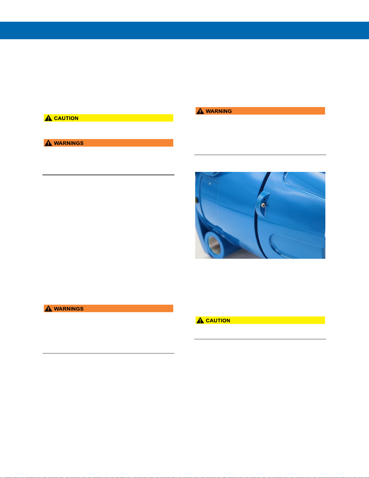
Cover Jam Screw
The cover jam screw should be properly installed
once the controller has been wired and tested in a
safe environment. The cover jam screw is intended to
prevent the removal of the controller cover in a
hazardous environment without the use of tools.
Using a M2 hex wrench, turn the screw clockwise until
the screw contacts the controller. Turn the screw an
additional 1/4 to 1/2 turn to secure the cover.
• Excess torque may damage the threads, screw
head, and wrench.
Page 23
ProtEX-MAX PD8-6210 Explosion-Proof Analog Input Batch Controller
Instruction Manual
23
Mounting
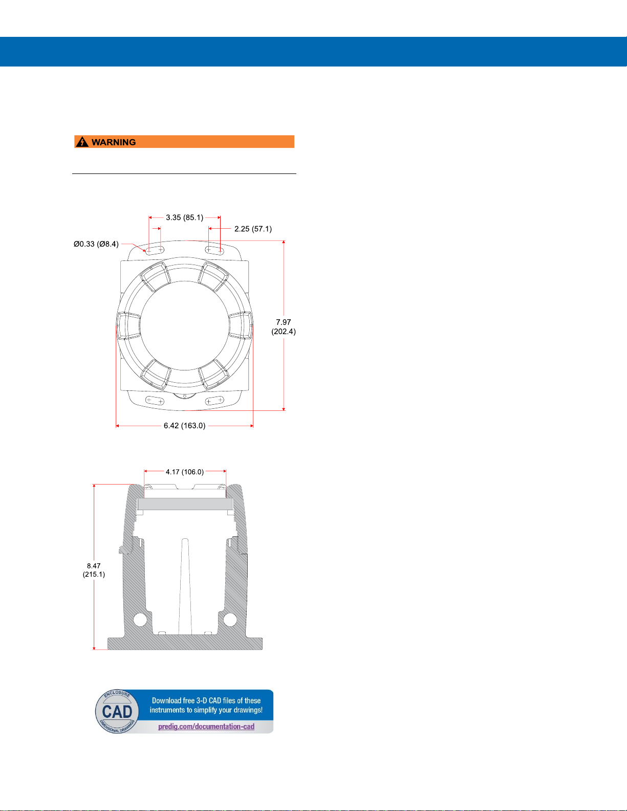
The ProtEX-MAX has four slotted mounting flanges
that may be used for pipe mounting or wall mounting.
Refer to Figure 1 and Figure 2 below.
• Do not attempt to loosen or remove flange bolts
while the controller is in service.
Mounting Dimensions
All units: inches (mm)
Figure 1. Enclosure Dimensions – Front View
Figure 2. Enclosure Dimensions –
Side Cross Section View
Wall Mounting Instructions
The controller can be mounted to any wall or flat
surface using the four provided mounting holes
located in the cast-in flanges. In addition, the internal
electronic assembly can be rotated to allow the
enclosure to be mounted in any position. To mount
the controller to a wall, follow these instructions:
• Prepare a section of wall approximately
7" x 8.5" (178 mm x 216 mm) for controller
mounting by marking with a pencil the
mounting holes (shown in Figure 1) on the
wall.
• Select the appropriate mounting screws for the
mounting surface to be used. The mounting
holes diameter is shown on Figure 1.
Note: Mounting screws are not included.
• Using a drill bit slightly smaller than the girth
of the mounting screws, pre-drill holes at the
mounting locations previously marked.
• Insert mounting screws into the four mounting
holes and screw them into the pre-drilled
holes.
Page 24
ProtEX-MAX PD8-6210 Explosion-Proof Analog Input Batch Controller
Instruction Manual
24
Pipe Mounting Instructions
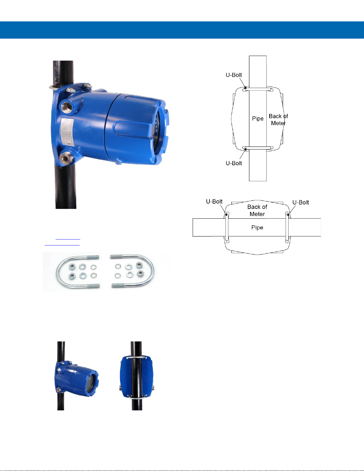
The controller can also be mounted to a pipe using an
optional U-Bolt kit. This kit includes two U-bolts, the
necessary hardware, and is available in zinc plated
steel (PDA6848) and 316 stainless steel
(PDA6848-SS).
To mount the controller using a U-Bolt kit, follow these
instructions:
• Orient the groove on the back of the
instrument with the pipe and secure it to the
pipe with the two U-bolts and hardware
provided.
Vertical Pipe Mounting
Horizontal Pipe Mounting
Page 25
ProtEX-MAX PD8-6210 Explosion-Proof Analog Input Batch Controller
Instruction Manual
25
Installation Overview
We recommend the following sequence for getting the
controller into service:
1. DO NOT apply AC or DC power to the controller.
2. Connect the controller to the PC with the USB
cable provided. DO NOT use a different USB cable.
3. If MeterView Pro (MVPro) is already installed in
your computer, then the program will launch
automatically in most systems. If the program
does not start automatically, double-click on the
MVPro icon.
4. If MVPro is not installed, follow the instructions
provided below.
5. Use MVPro to configure the controller for your
application.
6. Disconnect the USB cable from the controller.
7. Apply power and signal and check operation of
the controller.
8. Install the controller and put into service.
9. Make any programming adjustments using the
programming buttons.
MeterView Pro Software
The easiest and quickest way to program your
ProtEX-MAX controller is to use the FREE MeterView
Pro programming software. This software is loaded
into the controller and connects and installs directly to
your PC with the USB cable provided. DO NOT use a
different USB cable. We recommend that the first
thing you do after taking the controller out of the box
is connect the ProtEX-MAX to your PC with the
provided USB cable. DO NOT apply AC or DC power
to the controller while your PC is connected to the
controller as it will disrupt the USB connection. It is
not necessary to apply an input signal.
MeterView Pro programming software is intuitive, and
most customers can get their controller programmed
as they like without even looking in the manual.
Watch MeterView Pro Software Video at
www.predig.com/meterviewpro
MeterView Pro Installation
1. Connect one end of the provided USB cable
to the controller and the other end to the
computer. The computer will automatically
install the driver software it needs to talk to the
controller. Follow the on-screen instructions
and allow sufficient time for the process to
complete. This can take a few minutes. If the
process is interrupted, then it could leave the
system in an unstable condition.
• Only one controller may be connected at a time.
Attaching multiple controllers will cause a conflict
with the controller software.
• DO NOT apply AC or DC power to the controller
when using the USB connection.
• When using the USB connection, the controller
should only be connected to a computer when
both devices are in a non-hazardous area.
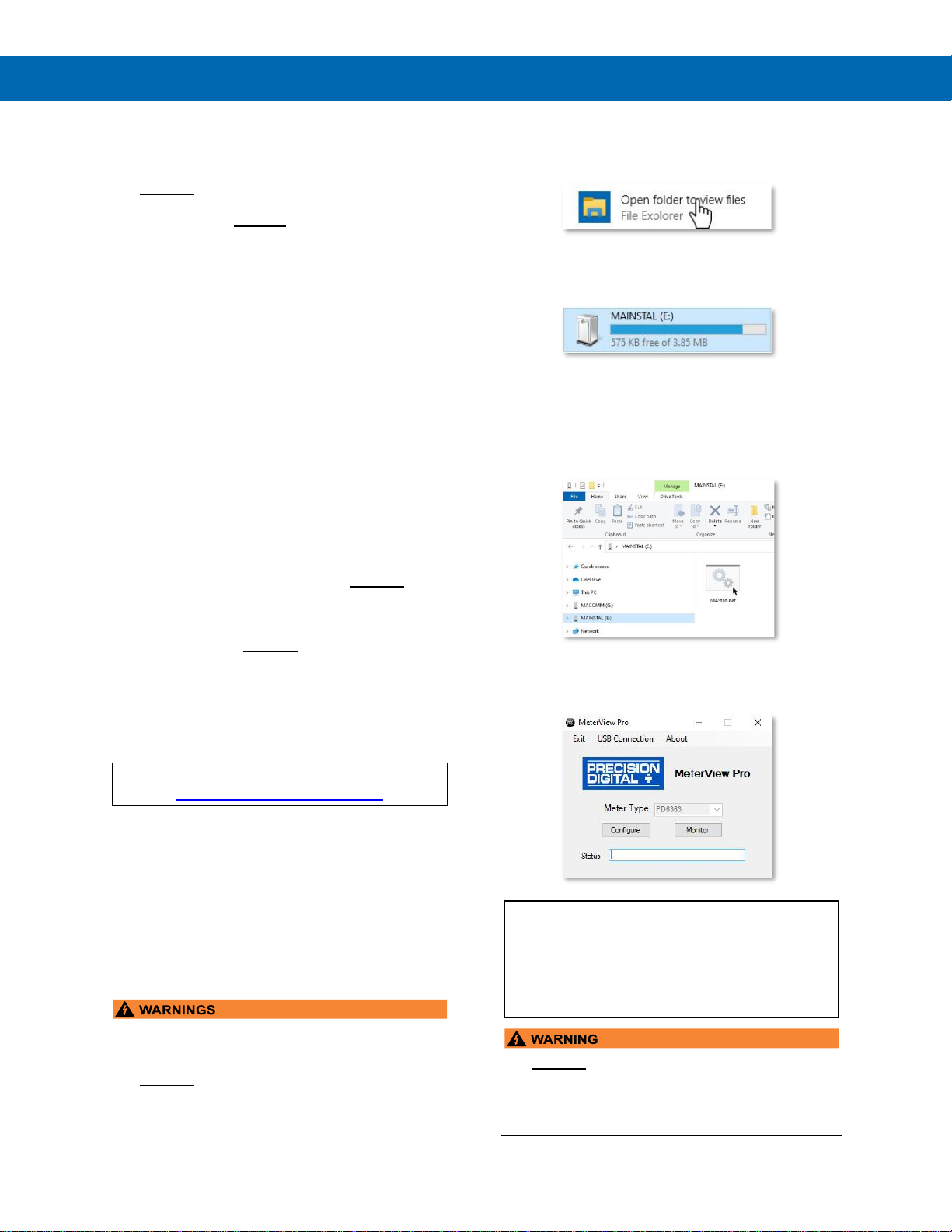
2. Once the driver is installed, an AutoPlay
dialog should appear for the drive
“MAINSTAL.” Click “Open folder to view
files.”
If the computer does not display an AutoPlay
dialog for the drive “MAINSTAL,” you should
open My Computer and double-click on the
drive labeled “MAINSTAL.”
3. Double-click on the file named “MAStart.”
The program will open a few windows and
install two programs on your computer.
Simply follow the on-screen instructions until
you see one of the dialogs below. If you
receive a “User Account Control” warning,
click “Yes.”
4. If there is an update available, click the
“Update” button to install the new version.
Otherwise, click “Configure” to begin
programming your controller.
Note: If you decide to update your MeterView Pro
software, once the installation has completed, you
will be asked if you want to update the setup files
located on the controller itself. This way, you will
always have the most current version on the
controller for future installs.
• DO NOT unplug the controller while the new
installation files are being written to it. The
controller will display uwrite during the process
and you will receive an on-screen notification
once the process is complete.
Page 26
ProtEX-MAX PD8-6210 Explosion-Proof Analog Input Batch Controller
Instruction Manual
26
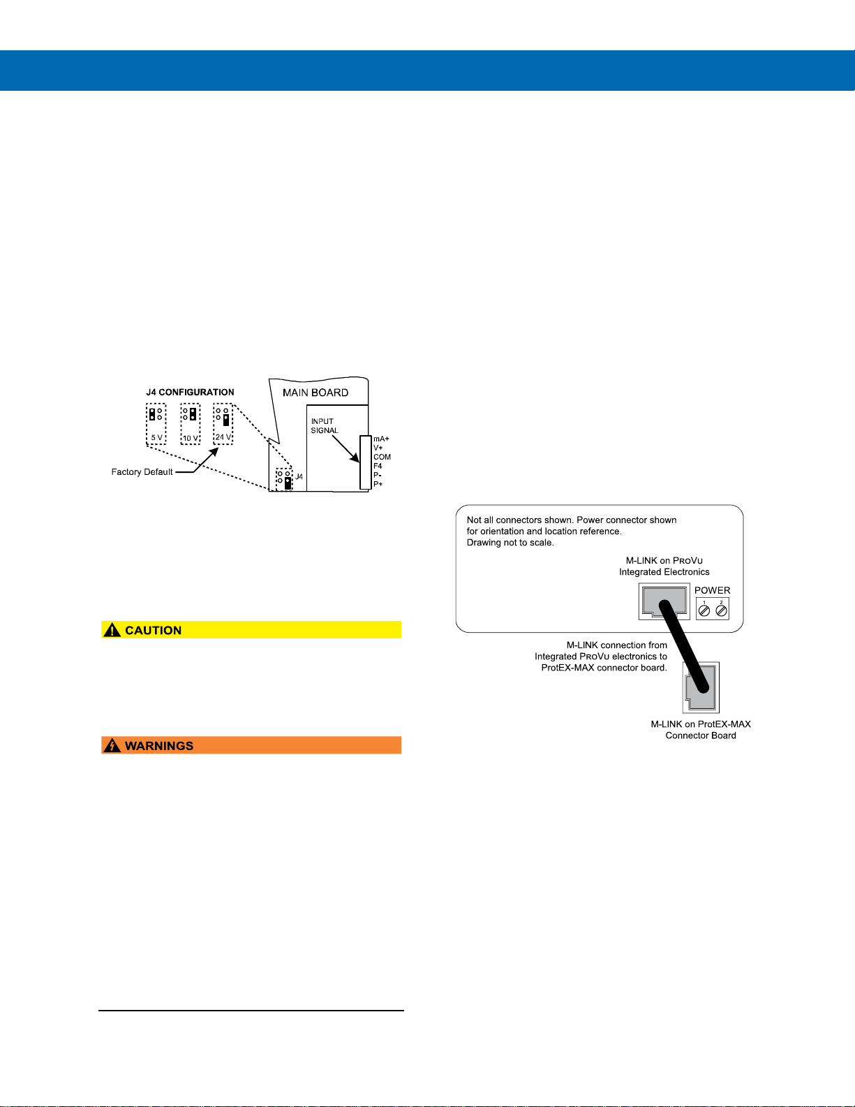
Transmitter Supply Voltage Selection (P+, P-)
All controllers, including models equipped with the
12-24 VDC power option, are shipped from the factory
configured to provide 24 VDC power for the
transmitter or sensor.
If the transmitter requires 5 or 10 VDC excitation, the
internal jumper J4 must be configured accordingly.
To access the voltage selection jumper:
1. Remove all the wiring connectors.
2. Unscrew the back cover.
3. Slide out the back cover by about 1 inch.
4. Configure the J4 jumper, located behind the
input signal connector, for the desired
excitation voltage as shown.
Figure 3. Transmitter Supply Voltage Selection
Connections
All connections are made to removable screw
terminal connectors located at the rear of the
controller.
• Use copper wire with 60°C or 60/75°C insulation
for all line voltage connections. Observe all safety
regulations. Electrical wiring should be performed
in accordance with all applicable national, state,
and local codes to prevent damage to the
controller and ensure personnel safety.
• Observe all safety regulations. Electrical wiring
should be performed in accordance with all
agency requirements and applicable national,
state, and local codes to prevent damage to the
controller and ensure personnel safety.
• Static electricity can damage sensitive
components.
• Observe safe handling precautions for
static-sensitive components.
• Use proper grounding procedures/codes.
• If the instrument is installed in a high voltage
environment and a fault or installation error
occurs, high voltage may be present on any lead
or terminal.
• Follow all fusing and wiring precautions
requirements for the instrument integrated to the
PD8 Series model number being connected.
To access the connectors, remove the enclosure
cover and unscrew the two captive screws that fasten
the electronics module. Signal connections are made
to de-pluggable connectors on the back of the
electronics module.
Some connectors may be provided already
connected. These connections are required for proper
operation of the ProtEX-MAX and should not be
removed unless instructed to by this manual.
Wires marked as being used for testing purposes
should be removed.
Grounding connections are made to the two ground
screws provided on the base – one internal and one
external.
After all connections have been completed and
verified, apply power to the unit.
Required & Factory Wired Connection
The ProtEX-MAX comes with a pre-wired connection.
This connection is detailed below and must be
maintained in order for the instrument to function
properly.
Figure 4. Integrated PROVU Required Connections
Page 27
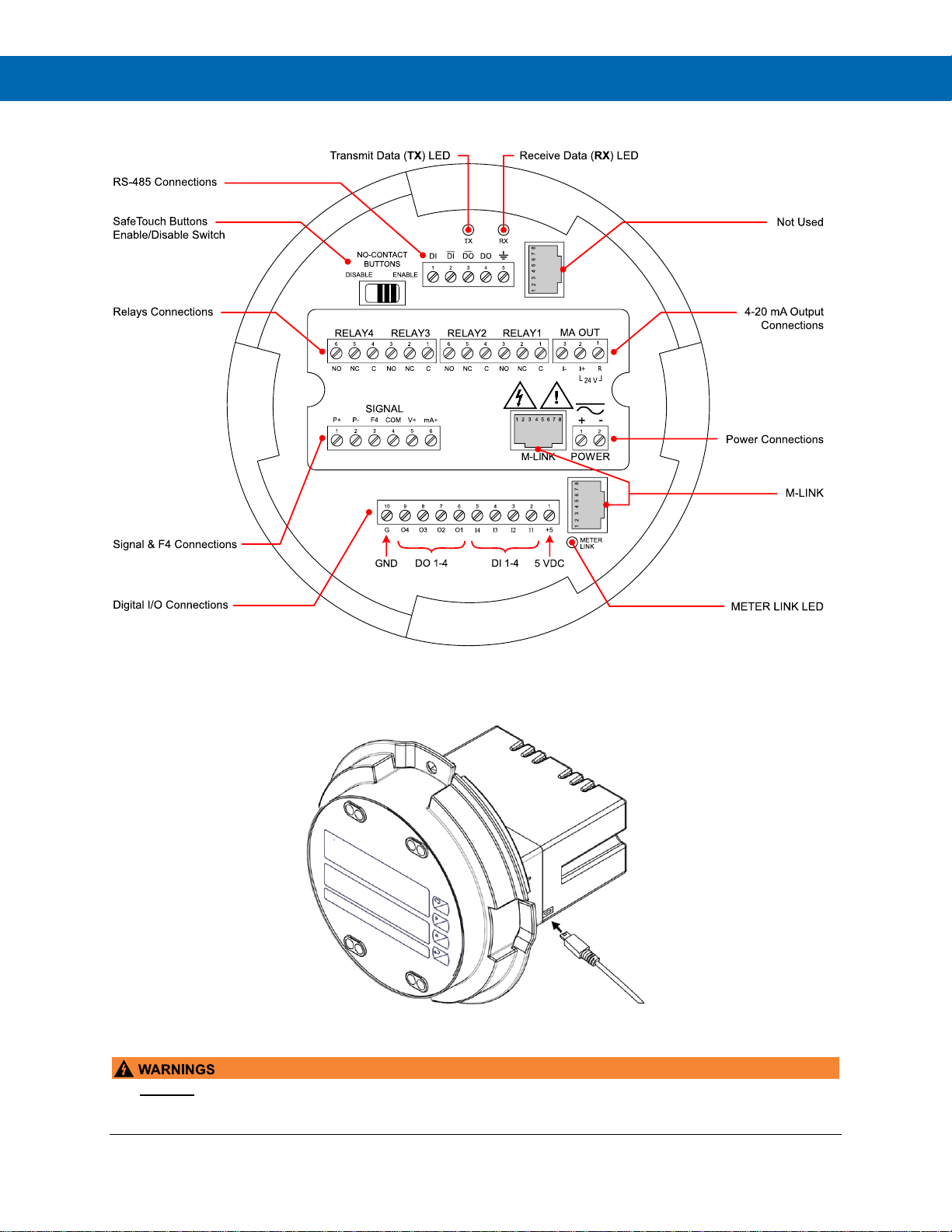
ProtEX-MAX PD8-6210 Explosion-Proof Analog Input Batch Controller
Instruction Manual
27
PROVU Electronics Module Layout for PD8-6210-6H7 and PD8-6210-7H7
Figure 5. PROVU Electronics Module Layout
USB Connection
Figure 6. USB Connection
• DO NOT disconnect the RJ45 M-LINK connector cable. Otherwise the instrument will not function properly.
• When using the USB connection, the controller should only be connected to a computer when both devices are
in a non-hazardous area.
Page 28
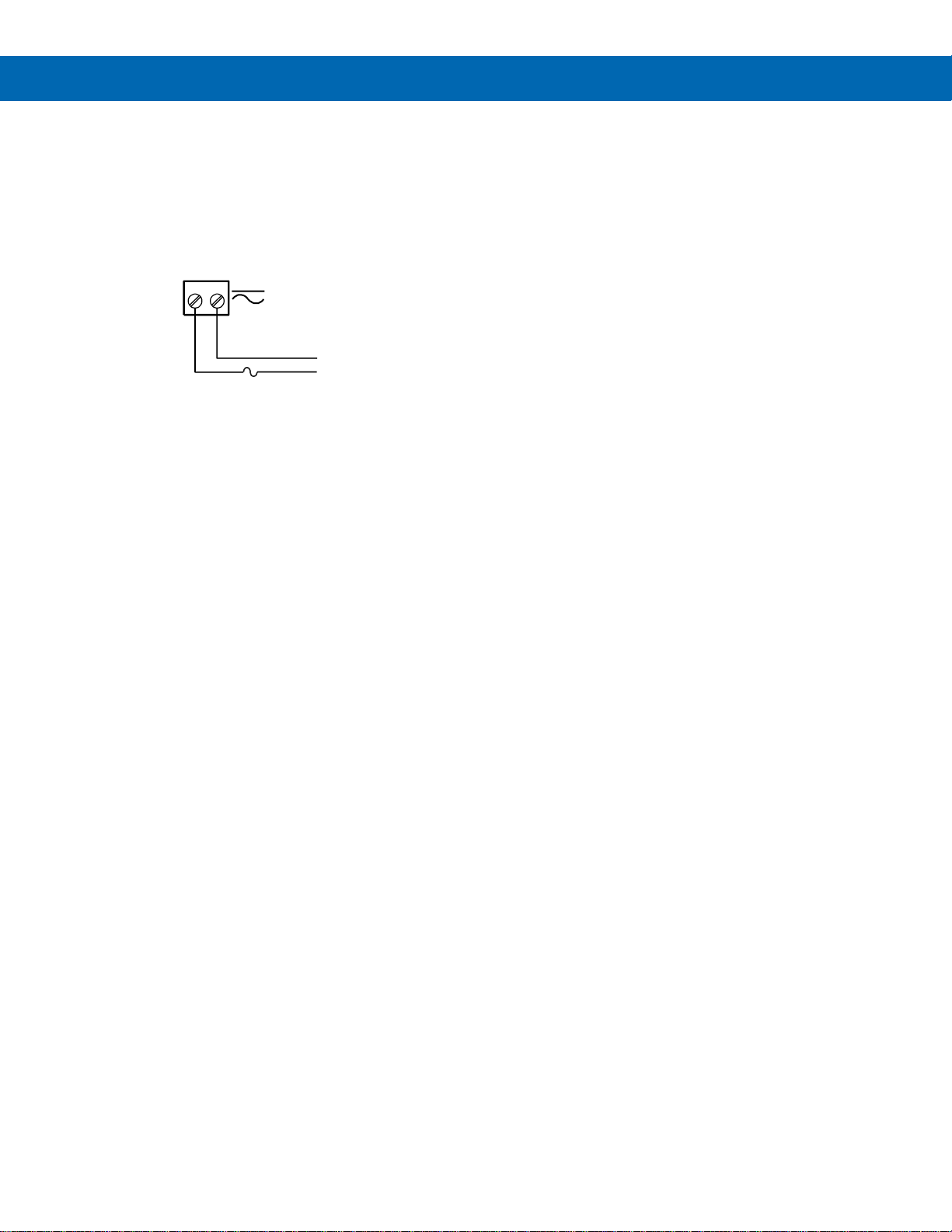
ProtEX-MAX PD8-6210 Explosion-Proof Analog Input Batch Controller
Instruction Manual
28
Power Connections
Power connections are made to a two-terminal
connector labeled POWER. The controller will operate
regardless of DC polarity connection. The + and symbols are only a suggested wiring convention. There
are separate models for low voltage and high voltage
power. See Ordering Information on page 7 for
details.
Figure 7. Power Connections
AC or DC
POWER
Required External Fuse:
5 A max, 250 V Slow Blow
POWER
+
-
Page 29
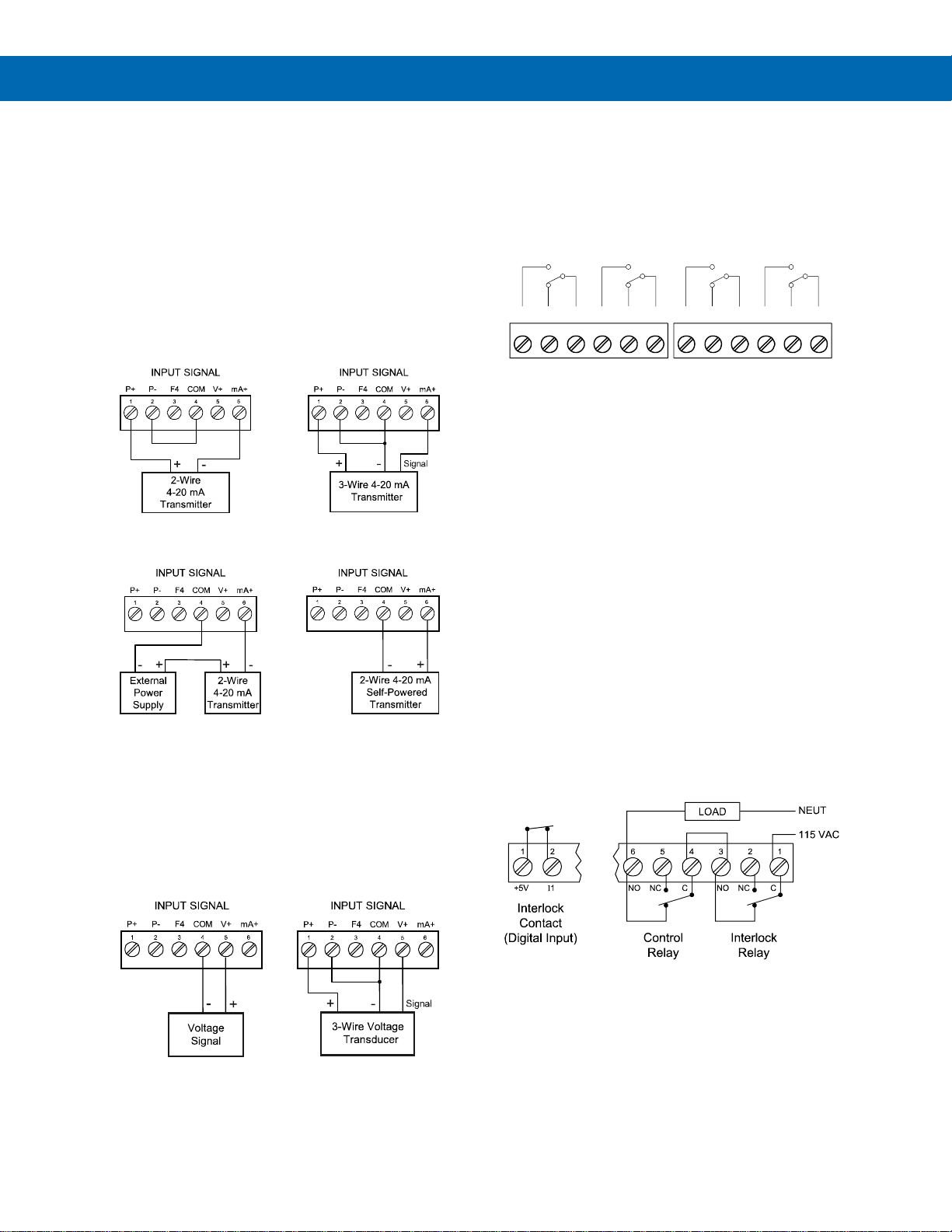
ProtEX-MAX PD8-6210 Explosion-Proof Analog Input Batch Controller
Instruction Manual
29
Signal Connections
Signal connections are made to a six-terminal
connector labeled SIGNAL. The COM (common)
terminal is the return for the 4-20 mA and the 10 V
input signals.
Current and Voltage Connections
The following figures show examples of current and
voltage connections.
There are no switches or jumpers to set up for current
and voltage inputs. Setup and programming is
performed through the programming buttons or
MeterView Pro software.
Figure 8. Transmitter Powered by Internal Supply
Figure 9. Transmitter Powered by Ext. Supply
or Self-Powered
The current input is protected against current
overload by a resettable fuse. The display may or
may not show a fault condition depending on the
nature of the overload.
The fuse limits the current to a safe level when it
detects a fault condition, and automatically resets
itself when the fault condition is removed.
Figure 10. Voltage Input Connections
The controller is capable of accepting any voltage from
-10 VDC to +10 VDC.
Relay Connections
Relay connections are made to two six-terminal
connectors labeled RELAY1 – RELAY4. Each relay’s
C terminal is common only to the normally open (NO)
and normally closed (NC) contacts of the
corresponding relay. The relays’ C terminals should
not be confused with the COM (common) terminal of
the INPUT SIGNAL connector.
Figure 11. Relay Connections
Interlock Relay Feature
As the name implies, the interlock relay feature
reassigns one, or more, alarm/control relays for use
as interlock relay(s). Interlock contact(s) are wired to
digital input(s) and activate the interlock relay. This
feature is enabled by configuring the relay, and the
corresponding digital input(s), see Setting Up the
Interlock Relay (Force On) Feature on page 50.
In the example below, an Interlock Contact switch is
connected to a digital input, which will be used to
force on (energize) the Interlock Relay. The Interlock
Relay and the Control Relay are connected in series
with the load.
• When the Interlock Contact is closed (safe), the
Interlock Relay energizes, allowing power to flow
to the Control Relay; the corresponding front
panel LED is on.
• When the Interlock Contact is open, the
corresponding front panel LED flashes (locked
out), the Interlock Relay is de-energized,
preventing power from flowing to the Control
Relay and the load.
Figure 12. Interlock Connection
C NONO NC NC C
RELAY4 RELAY3
4 36 5 2 1
C NONO NC NC C
RELAY2 RELAY1
4 36 5 2 1
Page 30
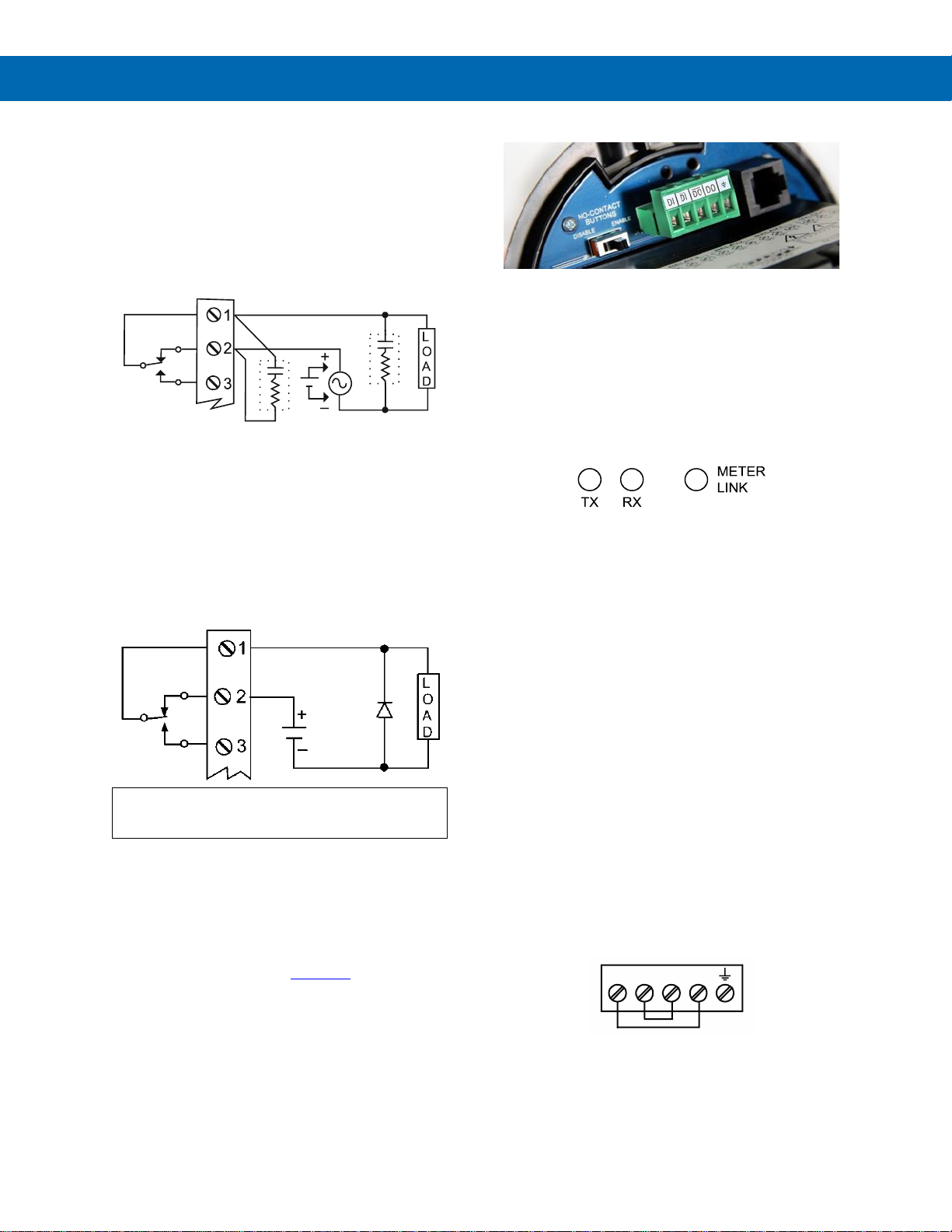
ProtEX-MAX PD8-6210 Explosion-Proof Analog Input Batch Controller
Instruction Manual
30
Switching Inductive Loads
The use of suppressors (snubbers) is strongly
recommended when switching inductive loads to
prevent disrupting the microprocessor’s operation.
The suppressors also prolong the life of the relay
contacts. Suppression can be obtained with
resistor-capacitor (RC) networks assembled by the
user or purchased as complete assemblies. Refer to
the following circuits for RC network assembly and
installation:
Figure 13. AC and DC Loads Protection
Choose R and C as follows:
R: 0.5 to 1 for each volt across the contacts
C: 0.5 to 1 µF for each amp through closed contacts
Notes:
1. Use capacitors rated for 250 VAC.
2. RC networks may affect load release time of solenoid
loads. Check to confirm proper operation.
3. Install the RC network at the controller's relay screw
terminals. An RC network may also be installed across
the load. Experiment for best results.
Use a diode with a reverse breakdown voltage two to three
times the circuit voltage and forward current at least as large
as the load current.
Figure 14. Low Voltage DC Loads Protection
RC Networks Available from Precision Digital
RC networks are available from Precision Digital and
should be applied to each relay contact switching an
inductive load. Part number: PDX6901.
Note: Relays are de-rated to 1/14th HP (50 watts) with an
inductive load.
RS-485 Connections
The RS-485 connections are made to a five terminal
connector used for Modbus® RTU serial
communications. The RS-485 terminals include
Transmit Data (DO) and (/DO), Receive Data (DI) and
(/DI), and Signal Ground. See Modbus RTU Serial
Communications (serial) on page 61 for more
information.
There are three diagnostic LEDs: Transmit Data (TX),
Receive Data (RX) and METER LINK to show when
the controller is transmitting and receiving data from
other devices.
Figure 15. RS-485 Diagnostic LEDs
RS-485 Multi-Drop Connection
When using more than one controller in a multi-drop
mode, each controller must be provided with its own
unique address. The controller address (Slave ID) can
be programmed between 1 and 247. The transmit
delay can be set between 0 and 199 ms. The parity
can be set to even, odd, or none with 1 or 2 stop bits.
To change the controller address:
1. Press and hold the Menu button for three
seconds to access Advanced Features menu of
the controller.
2. Press Up arrow until Serial (SEriaL) menu is
displayed and press Enter, Addres is displayed.
3. Press Enter to change controller address using
Right and Up arrow buttons. Press Enter to
accept.
4. Press Menu button to exit and return to Run
Mode.
Three-Wire Connection
In order to wire the five pins for use as a three-wire
half-duplex RS-485 connection, it is necessary to
create a jumper connection between DI to DO and /DI
to /DO- as shown below.
Figure 16. Three-Wire RS-485 Connection
C
R
C
R
__ __
DI DI DO DO
Page 31
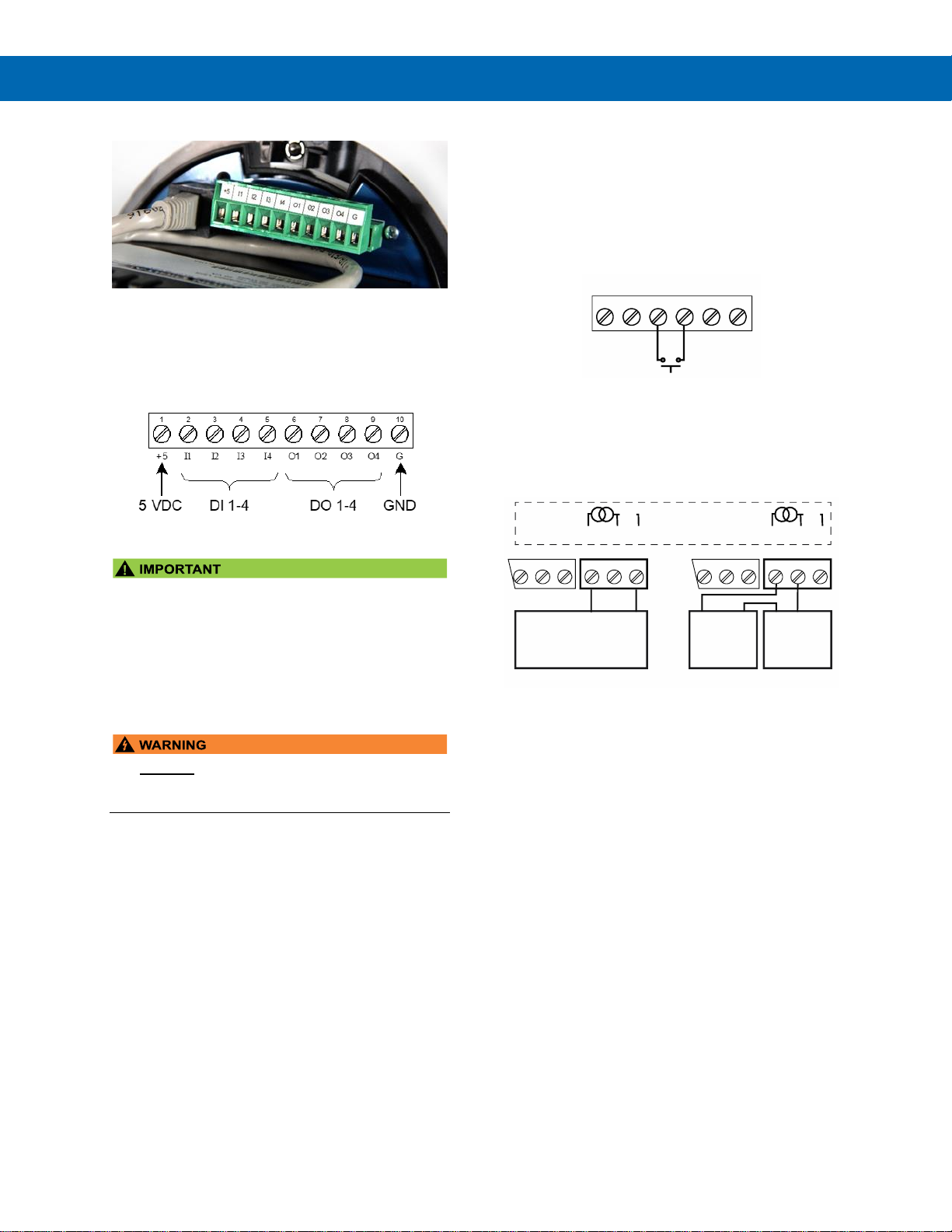
ProtEX-MAX PD8-6210 Explosion-Proof Analog Input Batch Controller
Instruction Manual
31
Digital I/O Connections
Digital inputs and outputs are provided in order to
expand the functionality of the controller. Digital input
connections are made via a push button or switch to
the appropriate digital input terminal and the +5 VDC
terminal. Digital output connections are made by
wiring from the appropriate digital output terminal to
the ground terminal.
Figure 17. Digital Input and Output Connections
The onboard digital inputs (1-4) are configured at the
factory to function identically to the front panel
pushbuttons (Menu, F1, F2, & F3) in order to work
with the SafeTouch buttons. Changing the
programming of the digital inputs will affect the
function of the SafeTouch buttons.
If you wish to change the behavior of the digital
inputs, re-assign F1-F3 to the desired function, then
change the corresponding digital input to match.
• DO NOT disconnect the RJ45 M-LINK connector
cable. Otherwise the instrument will not function
properly.
F4 Digital Input Connections
A digital input, F4, is standard on the controller. This
digital input should be connected with a normally
open contact across F4 and COM, or with an active
low signal applied to F4. It can be used to start/stop
the batch, reset the total, acknowledge/reset relays,
or to reset max/min values. See Function Keys &
Digital I/O Available Settings on page 64 for a
complete list of capabilities.
Figure 18. F4 Digital Input Connections
4-20 mA Output Connections
Connections for the 4-20 mA transmitter output are
made to the connector terminals labeled MA OUT.
The 4-20 mA output may be powered internally or
from an external power supply.
Figure 19. 4-20 mA Output Connections
P- COMP+ V+ mA+
3412 5
F4
6
4-20 mA Input
Remote Display, PLC,
Chart Recorder, Etc.
-
+
RI- I+
132
RELAY1
mA OUT
24 V
12-35 VDC
Power
Supply
+
4-20 mA
Input Meter
-+
RI- I+
132
RELAY1
321
-
24 V
mA OUT
Internal Power Supply
and Analog Output
321
Active Output Loop Passive Output Loop
Page 32
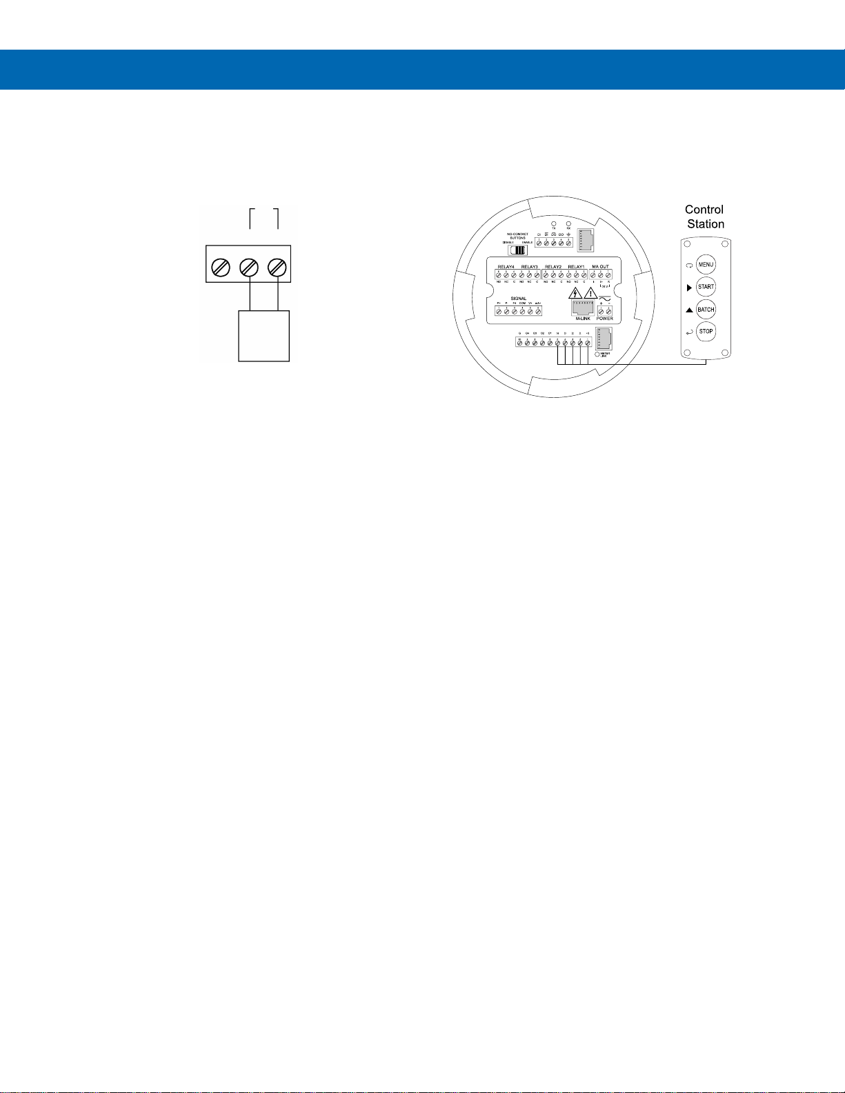
ProtEX-MAX PD8-6210 Explosion-Proof Analog Input Batch Controller
Instruction Manual
32
Analog Output Transmitter Power Supply
The internal 24 VDC power supply powering the
analog output may be used to power other devices if
the analog output is not used. The I+ terminal is the
+24 V and the R terminal is the return.
Figure 20. Analog Output Supply Powering Other
Devices
Remote Programming
The controller can be operated via the programming
buttons or a remote control station* with required
approvals to be located in a hazardous area using the
digital inputs.
* Control station must be approved for hazardous
locations
RI- I+
132
24 VDC
Powered
Device
24 V
+-
Page 33
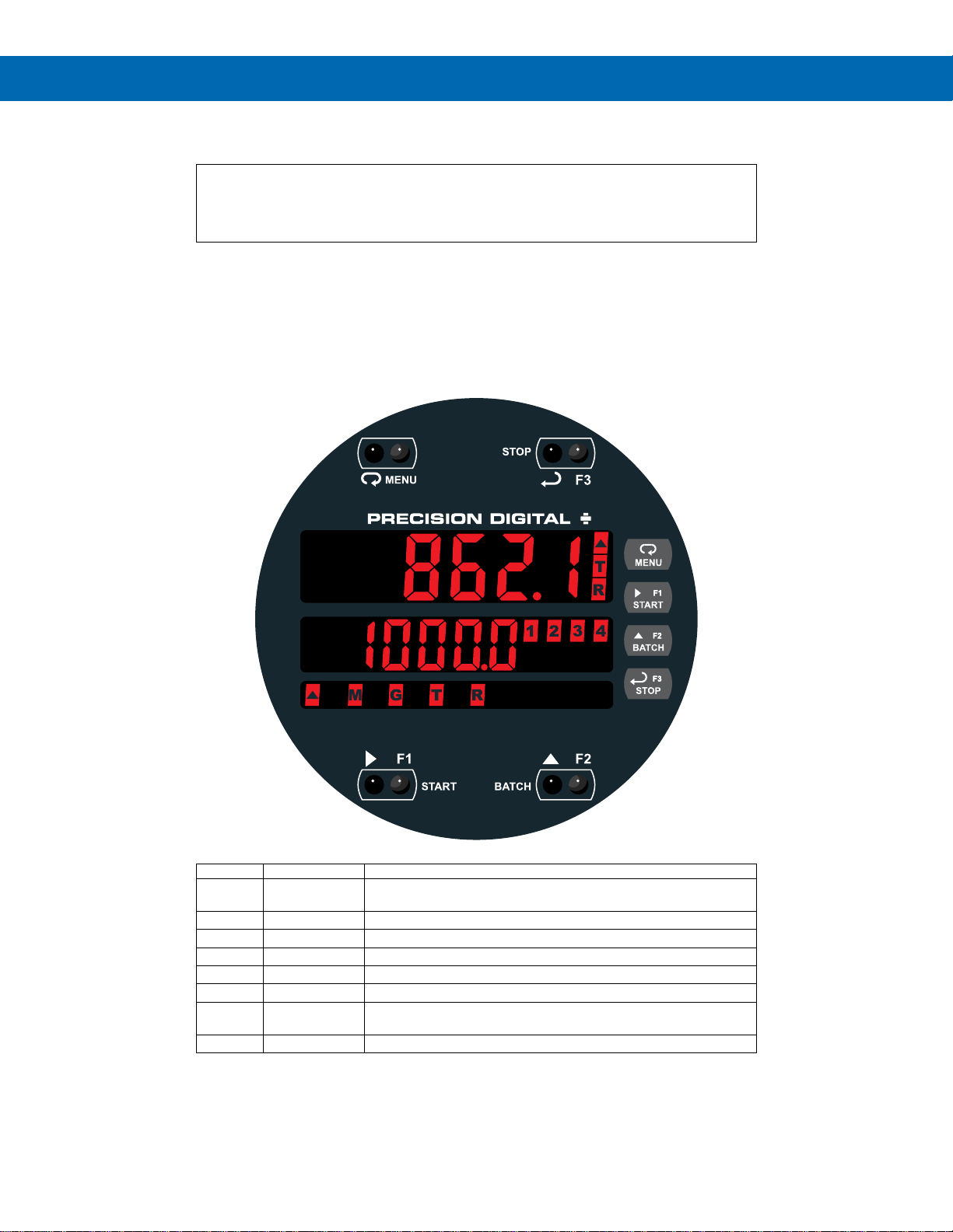
ProtEX-MAX PD8-6210 Explosion-Proof Analog Input Batch Controller
Instruction Manual
33
Setup and Programming
There is no need to recalibrate the controller when first received from the factory.
The controller is factory calibrated prior to shipment for milliamps and volts with
calibration equipment that is certified to NIST standards.
Overview
There are no jumpers to set for the controller input selection.
Setup and programming is done using MeterView Pro or through the programming buttons.
After power and input signal connections have been completed and verified, apply power to the controller.
LED Status Indicators
LED
State
Indication
1-4
Steady
Alarm condition based on set and reset points, independent of relay
status in certain configurations.
1-4
Flashing
Relay interlock switch open
1-4 & M
Flashing
Relay in manual control mode
R
Steady
Rate
T
Steady
Total
G & T
Steady
Grand Total
▲
Steady
Total overflow (“oF” is displayed to the left of total overflow and ▲
LED is illuminated)
M
Flashing
Analog output in manual control mode
Page 34
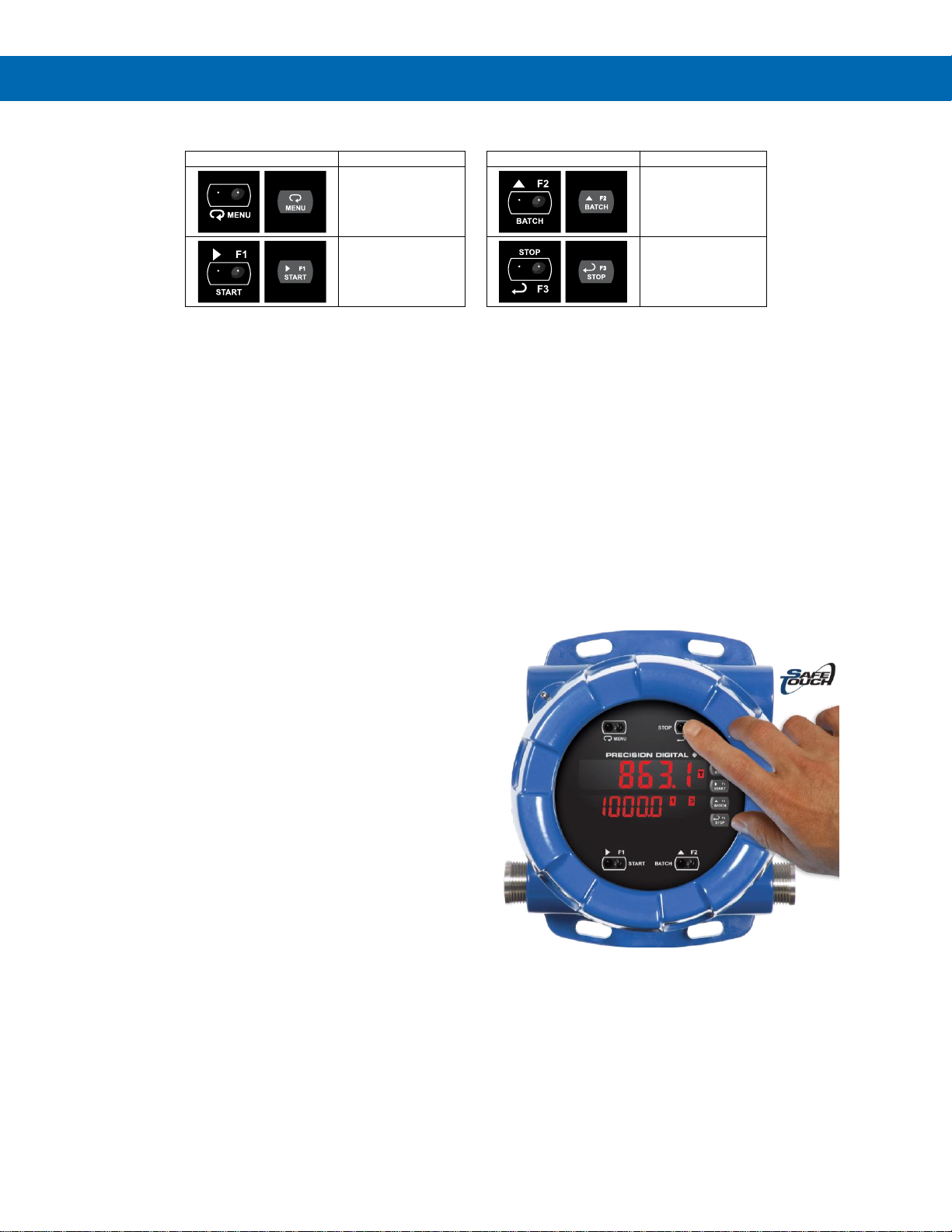
ProtEX-MAX PD8-6210 Explosion-Proof Analog Input Batch Controller
Instruction Manual
34
Programming Buttons
Button
Description Button
Description
Menu
BATCH
Up Arrow/F2
START
Right Arrow/F1
STOP
Enter/F3
• Press the Menu button to enter or exit the Programming Mode at any time.
• Press the Right arrow button to move to the next digit during digit or decimal point programming.
• Press or hold the Up arrow button to scroll through the menus, decimal point, or to increment the value of a digit.
• Press the Enter button to access a menu or to accept a setting.
• Press and hold the Menu button for three seconds to access the advanced features of the controller.
SafeTouch Buttons
The ProtEX-MAX is equipped with four sensors that
operate as through-glass buttons so that it can be
programmed and operated without removing the cover
(and exposing the electronics) in a hazardous area.
These buttons can be disabled for security by
selecting DISABLE on the switch labeled NO-CONTACT
BUTTONS located on the connector board.
To actuate a button, press one finger to the glass
directly over the marked button area. Then retract
finger more than three inches from the glass before
pressing the next button. When the cover is removed,
the four mechanical buttons located next to the
sensors are used. The sensors are disabled when a
mechanical button is pressed and will automatically
be re-enabled after 60 seconds of inactivity.
The SafeTouch Buttons are designed to filter normal
levels of ambient interference and to protect against
false triggering, however, it is recommended that the
SafeTouch Buttons be disabled (slide switch to
DISABLE) if there is an infrared interference source in
line-of-sight to the display.
The SafeTouch Buttons are configured by default to
duplicate the function of the front panel mechanical
pushbuttons associated with the integrated controller.
The symbols by each SafeTouch button correspond
to a mechanical button as shown in the above table.
SafeTouch Button Tips:
• To the extent possible, install the display facing
away from sunlight, windows, reflective objects
and any sources of infrared interference.
• Keep the glass window clean.
• Tighten the cover securely.
• Use a password to prevent tampering.
Page 35

ProtEX-MAX PD8-6210 Explosion-Proof Analog Input Batch Controller
Instruction Manual
35
Display Functions and Messages
The controller displays various functions and
messages during setup, programming, and operation.
The following table shows the main menu functions
and messages in the order they appear in the menu.
Display Functions and Messages
Display
Parameter
Action/Setting
Description
setup
Setup
Enter Setup menu
Input
Input
Enter Input selection menu
Volt
0-10 VDC
Set input for 10 VDC input
nmA
4-20 mA
Set input for 4-20 mA input
Total
Total
Enable or disable totalizer
features
unitS
Units
Select the display units/tags
rate
Rate
Select the display units for
rate
total
Total
Select the display units for
total
Gtotal
Grand Total
Select the display units for
grand total
Dec pt
Decimal
point
Set decimal point for rate,
total, grand total
prog
Program
Enter the Program menu
InCAL
Input
Calibration
Enter the Input Calibration
menu
sCalE
Scale
Enter the Scale menu
Cal
Calibrate
Enter the Calibrate menu
Inp 1
Input 1
Calibrate input 1 signal or
program input 1 value
Dis 1
Display 1
Program display 1 value
Inp 2
Input 2
Calibrate input 2 signal or
program input 2 value
(up to 32 points)
Dis 2
Display 2
Program display 2 value
(up to 32 points)
Error
Error
Error, calibration not
successful, check signal or
programmed value
T tb
Total time
base
Enter totalizer time base for
seconds, minutes, hours or
day.
T Cf
Total
conversion
factor
Enter the conversion factor
decimal point and the
conversion factor.
nmode
Batch mode
Automatic or manual batch
control
T dly
Time delay
Set time delay for automatic
batch restart
GT tb
Grand total
time base
Program grand total time
base
Display Functions and Messages
Display
Parameter
Action/Setting
Description
GT CF
Grand total
conversion
factor
Program grand total
conversion factor
GT rst
Grand total
reset
Program grand total reset
mode: auto or manual
dsplay
Display
Enter the Display menu
Line 1
Display
Line 1
Press Enter to assign the
main display parameter
(default: PV or rate)
Line 2
Display
Line 2
Press Enter to assign the
second display parameter
(default: total)
d-Inty
Display
intensity
Set display intensity level
from 1 to 8
RELaY
Relay
Enter the Relay menu
Assign
Assignment
Assign relays to rate, total
(batch control), grand total,
or Modbus controlled.
Asign1
Assign 1
Relay 1-2 assignment
TotaL
Total
Assign relay to batch
control
Gtotal
Grand total
Assign relay to grand total
nmbus
Modbus
Assign relay to Modbus
input
rate
Rate
Assign relay to rate
precls
Batch total
relay
pre-close
For relays beyond the first
assigned to total, a
pre-close amount may be
entered.
RLY 1
Relay 1
Relay 1 setup
Act 1
Action 1
Set relay 1 action1
Auto
Automatic
Set relay for automatic reset
A-nman
Automanual1
Set relay for automatic &
manual reset any time
1
(relays assigned to rate)
LatcH
Latching1
Set relay for latching
operation (relays assigned
to rate) 1
Lt-CLr
Latchingcleared1
Set relay for latching
operation with manual
reset only after alarm
condition has cleared
(relays assigned to rate) 1
Altern
Alternate
Not applicable to batch
controller
Sanmpl
Sampling
Set relay for sampling
operation (rate or GT)
OFF
Off
Disable relay and front
panel status LED
(Select Off to enable
Interlock feature)
Preset
Preset
Set batch preset
Set 1
Set 1
Program set point 1
Page 36
ProtEX-MAX PD8-6210 Explosion-Proof Analog Input Batch Controller
Instruction Manual
36
Display Functions and Messages
Display
Parameter
Action/Setting
Description
RSt 1
Reset 1
Program reset point 1
RLY 2
Relay 2
Relays 2-4 setup.
FaiLSF
Fail-safe
Enter Fail-safe menu
FLS 1
Fail-safe 1
Set relay 1 fail-safe
operation
on
On
Enable fail-safe operation
off
Fail-safe off
Disable fail-safe operation
DeLAY
Delay
Enter relay Time Delay
menu
DLY 1
Delay 1
Enter relay 1 time delay
setup
On 1
On
Set relay 1 On time delay
OFF 1
Off
Set relay 1 Off time delay
break
Loop break
Set relay condition if loop
break detected
(For mA input only)
iGnorE
Ignore
Ignore loop break condition
(Processed as a low signal
condition)
On
On
Relay goes to alarm
condition when loop break
is detected
OFF
Off
Relay goes to non-alarm
condition when loop break
is detected
Aout
Analog
output
Enter the Analog output
scaling menu
Dis 1
Display 1
Program display 1 value
Out 1
Output 1
Program output 1 value
(e.g. 4.000 mA)
Dis 2
Display 2
Program display 2 value
Out 2
Output 2
Program output 2 value
(e.g. 20.000 mA)
reset
Reset
Press Enter to access the
Reset menu
Rst Hi
Reset high
Press Enter to reset max
display
Rst Lo
Reset low
Press Enter to reset min
display
Rst HL
Reset
high & low
Press Enter to reset max &
min displays
Rst t
Reset total
Press Enter to reset total
Rst Gt
Reset
grand total
Press Enter to reset grand
total
Rst bc
Reset
batch count
Press Enter to reset batch
count
Display Functions and Messages
Display
Parameter
Action/Setting
Description
Contrl
Control
Enter Manual Control menu
Auto
Automatic
Press Enter to set controller
for automatic operation
nmAn
Manual
Press Enter to manually
control relays or analog
output operation
`pass
Password
Enter the Password menu
Pass 1
Password 1
Set or enter Password 1
Pass 2
Password 2
Set or enter Password 2
Pass 3
Password 3
Set or enter Password 3
Total
Total
password
Set or enter password for
manual reset
Gtotal
Grand total
password
Set or enter password for
manual reset
nonrst
Nonresettable
Non-resettable grand total
set after entering “050873”
for Gtotal password
unloc
Unlocked
Program password to lock
controller
locd
Locked
Enter password to unlock
controller
999999
-99999
Flashing
display
Overrange condition
Underrange condition
• During operation, only the STOP button will
function, to stop/pause the batch. As a result,
relay alarms cannot be manually reset.
Page 37
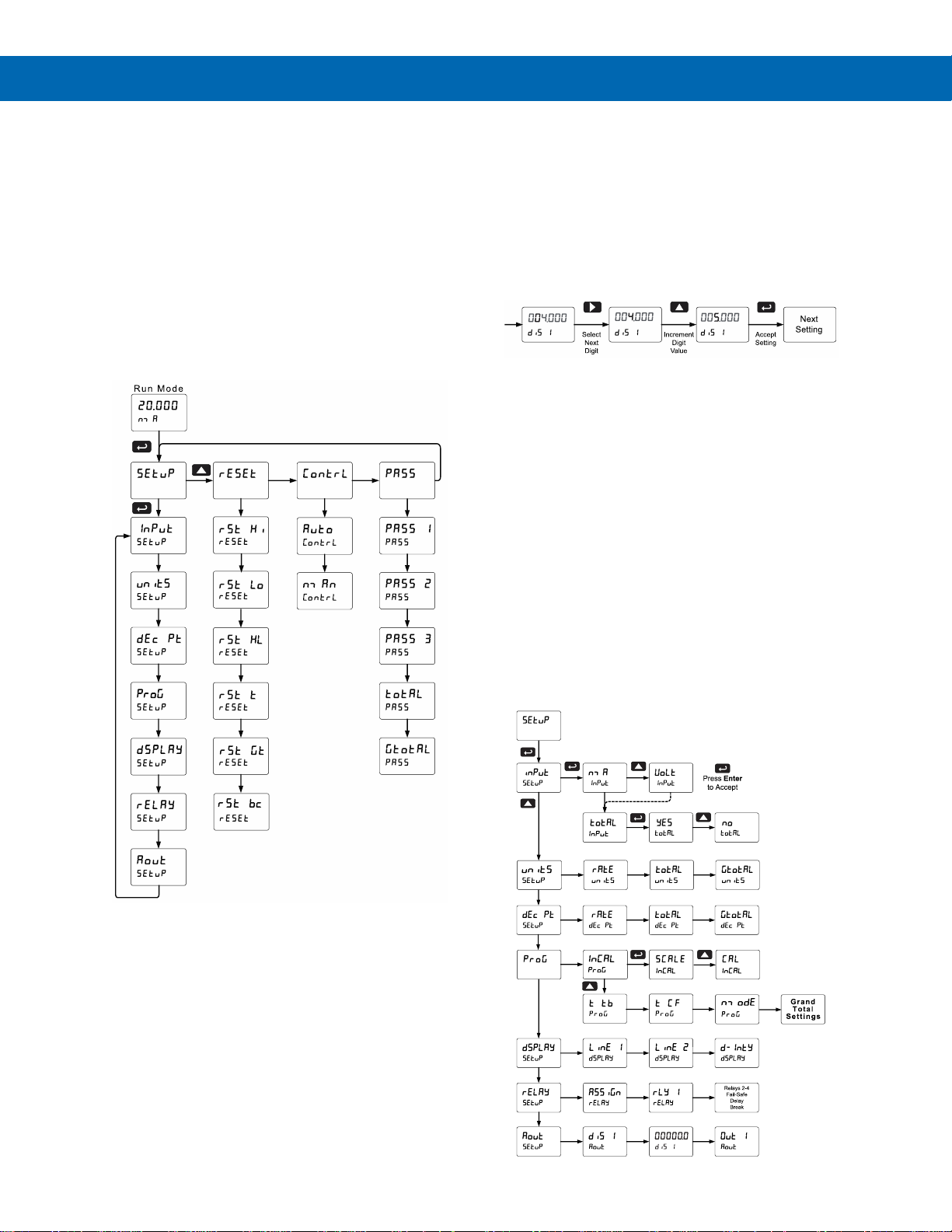
ProtEX-MAX PD8-6210 Explosion-Proof Analog Input Batch Controller
Instruction Manual
37
Main Menu
The main menu consists of the most commonly used
functions: Setup, Reset, Control, and Password.
• Press Menu button when a batch is not running
to enter Programming Mode then press the Up
arrow button to scroll main menu.
• Press Menu, at any time, to exit and return to
Run Mode. Changes made to settings prior to
pressing Enter are not saved.
• Changes to the settings are saved to memory
only after pressing Enter.
• The display moves to the next menu every time a
setting is accepted by pressing Enter.
Setting Numeric Values
The numeric values are set using the Right and Up
arrow buttons. Press Right arrow to select next digit
and Up arrow to increment digit value. The digit being
changed is displayed brighter than the rest.
Press and hold up arrow to auto-increment the display
value.
Press the Enter button, at any time, to accept a
setting or Menu button to exit without saving changes.
Setting Up the Batch Controller (setup)
The Setup menu is used to select:
1. Input signal the controller will accept
2. Enable or disable totalizer and batching
features
3. Select the display units/tags
4. Decimal point position
5. Program menu for scaling or calibration,
totalizer setup, manual or automatic batch
mode
6. Display parameter and intensity
7. Relay operation
8. 4-20 mA analog output scaling
Press the Enter button to access any menu or press
Up arrow button to scroll through choices. Press the
Menu button to exit at any time.
Page 38
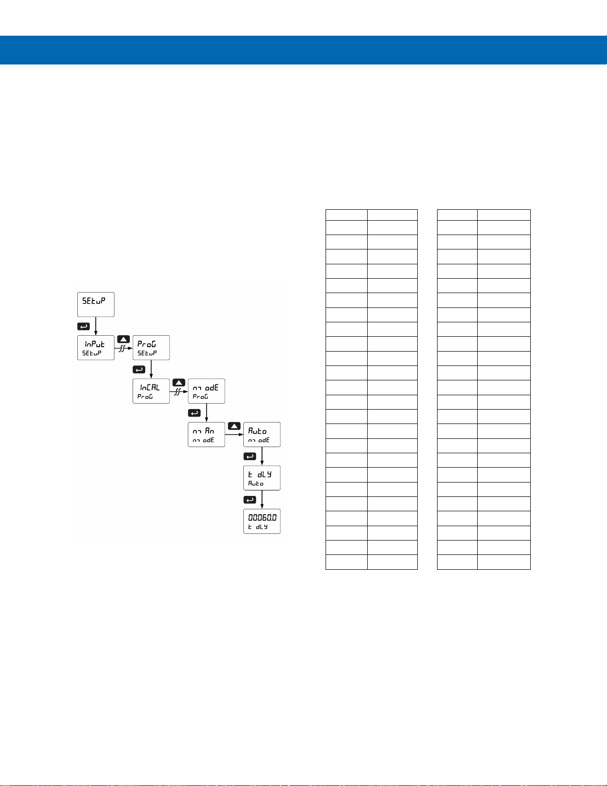
ProtEX-MAX PD8-6210 Explosion-Proof Analog Input Batch Controller
Instruction Manual
38
Setting the Input Signal (Input)
Enter the Input menu to set up the controller to accept
current (nmA) or voltage (Volt) inputs.
The current input is capable of accepting any signal
from 0 to 20 mA. Select current input to accept
0-20 mA or 4-20 mA signals.
The voltage input is capable of accepting any signal
from -10 to +10 VDC. Select voltage input to accept
0-5, 1-5, 0-10, or 10 VDC signals.
Setting the Totalizer & Batch Control Features (total)
After the input type is entered, set the total
parameter to “Yes” to enable batch control (this is set
by default). If the total features are disabled, most
batching features and functions are hidden from the
menus.
Setting the Input Units or Custom Tags (units)
Enter the input unit or custom tag that will be
displayed if alternating rate, total, or grand total and
units is selected in the units menu, or d unit is
selected as the Second display parameter. See the
Setting the Display Parameter & Intensity (dsplay)
flow chart on page 42 to access the display menu to
show the unit or tag on the second display. The
engineering units or custom legends can be set using
the following 7-segment character set:
Display
Character
Display
Character
0
0
k K 1
1
l
L
2
2
nm
m
3
3
n n 4
4
O O 5
5
o o 6
6
p P 7
7
q q 8
8
r r 9
9
s S A
A
t t b
b
u u C
C
V V c
c
uw w d
d
x
X
e
E
y
Y
f
F
z Z g
G
- - 9
g
/ / H
H
[ ] h
h
] [ I
I
= = i
i
!
Degree(<)
j
J
Space
Notes:
1. Degree symbol represented by (<) if programming with
MeterView Pro.
2. The letters “m” and “w” use two 7-segment LEDs each;
when selected the characters to the right are shifted
one position.
3. Press and hold up arrow to auto-scroll the characters in
the display.
Page 39
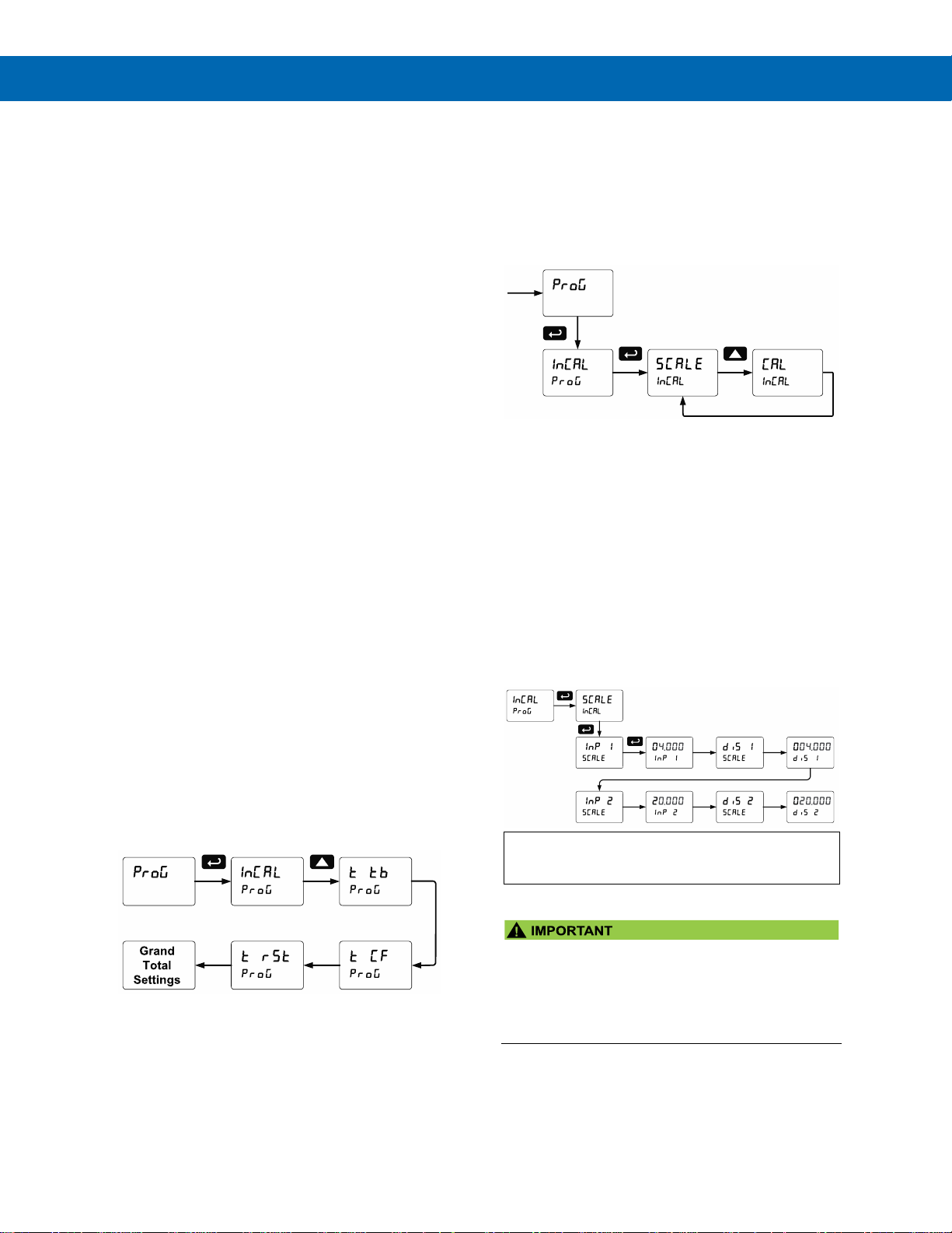
ProtEX-MAX PD8-6210 Explosion-Proof Analog Input Batch Controller
Instruction Manual
39
Setting the Decimal Point (dEc pt)
The decimal point may be set with up to five decimal
places or with no decimal point at all. The rate, total,
and grand total decimal points are independent.
The decimal point selection should be made prior to
scaling, calibrating or programming the controller.
Press the Up arrow to move the decimal point one
place to the left. Press the Right arrow to move the
decimal point one place to the right.
Programming the Batch Controller (prog)
The controller may either be scaled (SCALE) without
applying an input or calibrated (Cal) by applying an
input. The controller comes factory calibrated to NIST
standards, so for initial setup, it is recommended to
use the (SCALE) function.
The Program menu contains the following menus:
1. Input Calibration
a. Scale without a signal source
b. Calibrate with a signal source
2. Total time base & conversion factor
3. Batch mode
a. Manual batch control
b. Automatic batch control
4. Grand total time base & conversion factor
5. Grand total reset mode
a. Manual reset
b. Automatic reset with time delay
The process inputs may be calibrated or scaled to any
display value within the range of the controller.
Note: The Scale and Calibrate functions are exclusive of
each other. The controller uses the last function
programmed. Only one of these methods can be employed
at a time. The Scale and Calibrate functions can use up to
32 points (default is 2). The number of points should be set
in the Advanced menu prior to scaling and calibration of the
controller. See Multi-Point Linearization (Linear) menu on
page 62 for details.
Additional parameters, not needed for most
applications, are programmed in the Advanced
Features menu; see Advanced Setup & Programming
on page 59.
Input Calibration Method (InCAL)
There are two methods of calibrating (or scaling) the
display to show the correct engineering units.
• Use the Scale menu to enter the scaling without a
signal source.
• Use the Calibrate menu to apply a signal from a
signal source.
Note: The Scale and Calibrate functions are exclusive of
each other. The controller uses the last function
programmed. Only one of these methods can be employed
at a time. The Scale and Calibrate functions can use up to
32 points (default is 2). The number of points should be set
in the Advanced menu prior to scaling and calibration of the
controller. See Multi-Point Linearization (
Linear
) menu on
page 62 for details.
Scaling the Controller (SCALE)
The 4-20 mA and the 10 VDC inputs can be scaled
to display the process variable in engineering units.
A signal source is not needed to scale the controller;
simply program the inputs and corresponding display
values.
For instructions on how to program numeric values
see Setting Numeric Values, page 37.
• Reverse Scaling
The controller can be scaled so that 4 mA
represents the high end of the process value
range being measured by the transmitter and
20 mA represents the low end of the process
value range.
Page 40
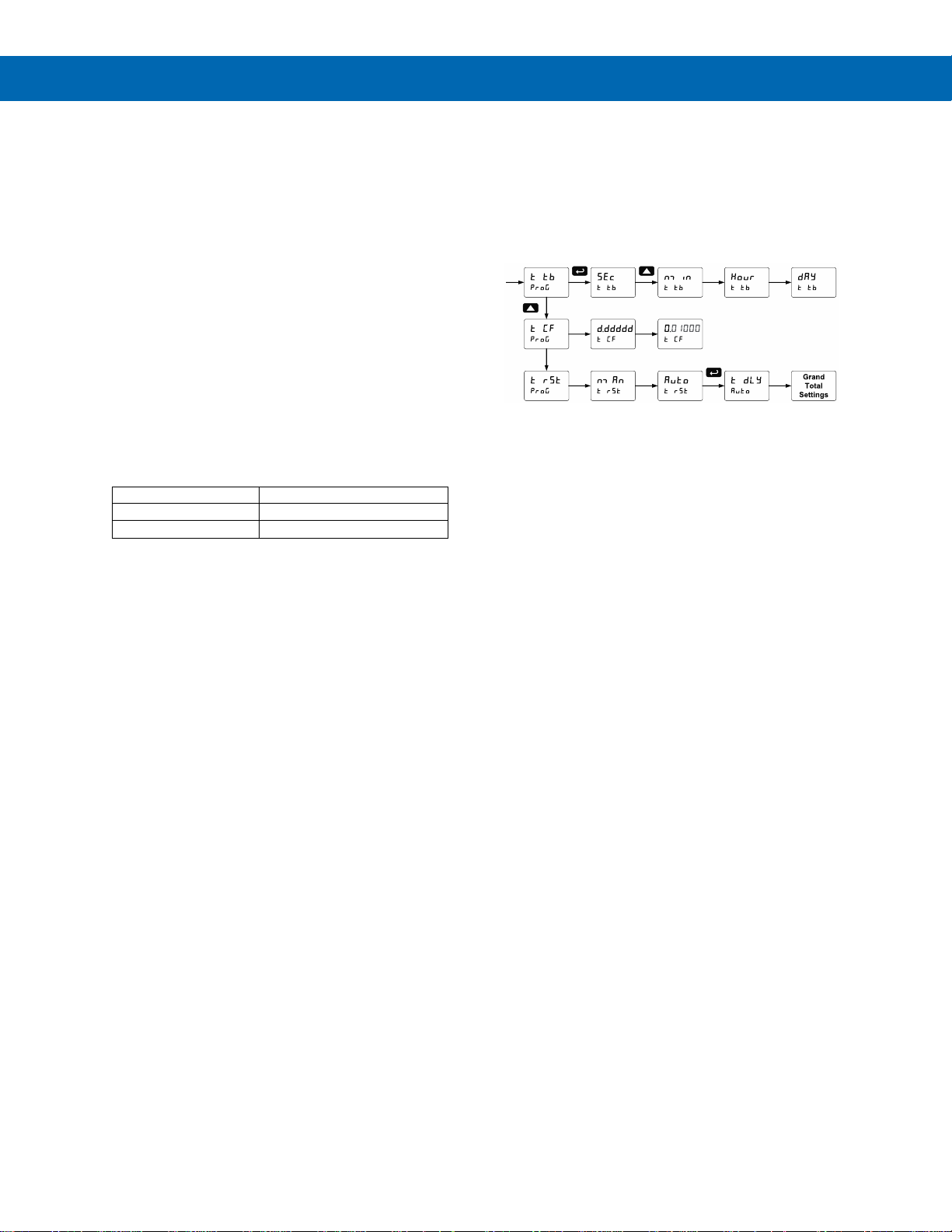
ProtEX-MAX PD8-6210 Explosion-Proof Analog Input Batch Controller
Instruction Manual
40
Error Message (Error)
An error message indicates that the calibration or scaling
process was not successful.
After the error message is displayed, the controller
reverts to input 2 during calibration or scaling and to
input 1 during internal calibration, allowing the
appropriate input signal to be applied or programmed.
The error message might be caused by any of the
following conditions:
1. Input signal is not connected to the proper
terminals, or it is connected backwards.
2. Wrong signal selection in Setup menu.
3. Minimum input span requirements not
maintained.
4. Input 1 signal inadvertently applied to calibrate
input 2.
Minimum Input Span
The minimum input span is the minimum difference
between input 1 and 2 signals required to complete
the calibration or scaling of the controller.
Input range
Input 1 & input 2 span
4-20 mA
0.15 mA
10 VDC
0.10 VDC
Time Base, Total Conversion Factor & Total Reset
The time base, total conversion factor, and total reset
menus are located in the Program menu.
The total and grand total have their own independent
settings. This means that one can be displaying the
value in gallons while the other displays in million
gallons, liters, m3, etc.
Time Base
The time base is the amount of time over which the
rate parameter should accrue. For example, if the rate
was ten and the time base was in minutes, then the
total would increase by ten every one minute.
Total & Grand Total Conversion Factor
The total & grand total conversion factor is the
amount by which the rate is multiplied before it is
added to the total or grand total.
For Example, if the rate was 10,000 gallons per
minute and the total conversion factor was 0.001, the
total would increase by 10 every minute. This is
useful, for instance, if you want to show rate in gallons
and total in thousands of gallons.
Page 41

ProtEX-MAX PD8-6210 Explosion-Proof Analog Input Batch Controller
Instruction Manual
41
Batch Start Mode (nmode)
Manual Batch Control
The batch controller may operate in manual or
automatic mode. In manual mode, the controller
operates as described in Manual Batch Control on
page 55.
Automatic Batch Control
In automatic mode, the controller operates as
described in Automatic Batch Control on page 56.
The batch process will start when the operator
presses the START button and it will automatically
restart after a completed batch. The time delay for the
restart may be 0.1 to 999.9 seconds (t dly).
Automatic batch start will only occur after a successful
batch. A manually stopped batch will require a manual
start to begin a new batch process.
Grand Total Reset
The grand total can be programmed for manual or
automatic reset. In the automatic reset mode, a
programmable time delay is available to reset the
grand total after the assigned preset is reached.
The totals can also be reset via the front panel button,
via a switch across the F4 terminal, digital inputs, or
via a Modbus command.
Non-Resettable Totalizer
The grand total can be programmed as a
non-resettable total, see Grand Total Reset Password
& Non-Resettable Total on page 52 for details.
Calibrating the Controller with External Source (Cal)
The controller can be calibrated to display the process
variable in engineering units by applying the
appropriate input signal and the corresponding
display value.
The use of a calibrated signal source is strongly
recommended to calibrate the controller.
Note: Inputs for the above example are:
Input 1: 4.00 mA; Display 1: 0.0 Gallons
Input 2: 20.00 mA; Display 2: 15000.0 Gallons
Warm up the controller for at least 15 minutes
before performing calibration to ensure specified
accuracy.
Page 42
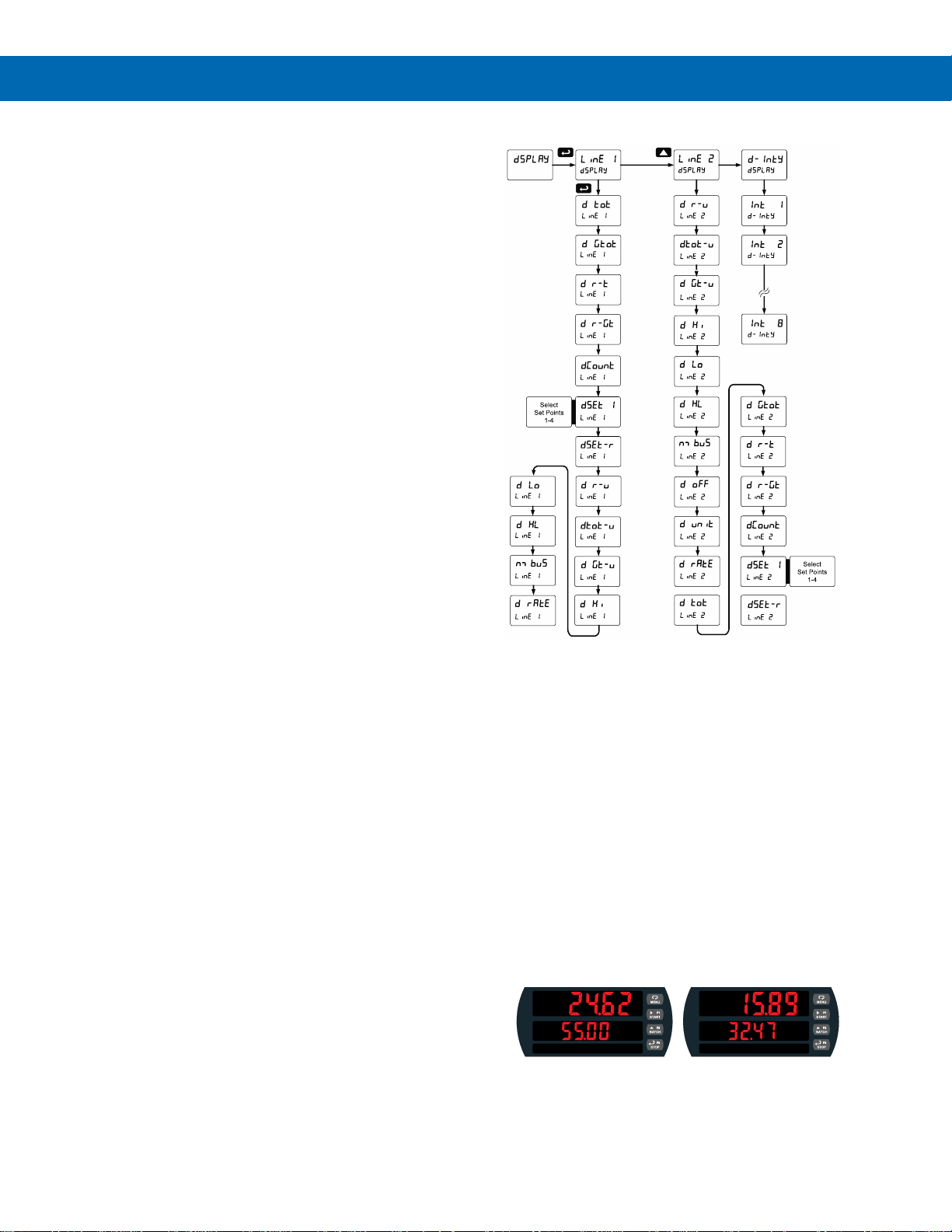
ProtEX-MAX PD8-6210 Explosion-Proof Analog Input Batch Controller
Instruction Manual
42
Setting the Display Parameter & Intensity (dsplay)
Display line 1 (line 1) can be programmed to
display:
1. Display total
2. Display grand total
3. Toggle rate and total
4. Toggle rate and grand total
5. Display batch count
6. Relay set points
7. Toggle preset and rate
8. Toggle rate and units
9. Toggle total and units
10. Toggle grand total and units
11. Display max and min values
12. Display Modbus input
13. Display rate value
Display line 2 (line 2) can be programmed to
display:
1. Toggle rate and units
2. Toggle total and units
3. Toggle grand total and units
4. Display max and min values
5. Display Modbus input
6. Off (no display)
7. Display rate units
8. Display rate
9. Display total
10. Display grand total
11. Toggle rate and total
12. Toggle rate and grand total
13. Display batch count
14. Relay set points
15. Toggle preset and rate
After setting up the input and the display, press the
Menu button to exit programming and skip the rest of
the setup menu. Press the Menu button again and the
Up arrow to reach the Program menu and complete
the scaling or calibration of the controller.
Display Menu
Display Intensity (d-Inty)
The controller has eight display intensity levels to give
the best performance under various lighting
conditions. Select intensity 8 for outdoor applications.
The default intensity setting is 6.
Display Configurations
The main and second displays may be assigned to
rate, total, grand total, batch count, preset, set points,
units (second display only), alternating R & T, R &
GT, preset & rate, max & min, or a Modbus display
register. Any rate/total/grand total display may be
programmed to alternate with a custom unit or tag.
The default display configuration consists of a main
display of batch total and a second display of the
batch preset.
The display can also be set up, so batch total is on
the main display and rate is on the second display.
Batch Total and Preset Batch Total and Rate
Page 43
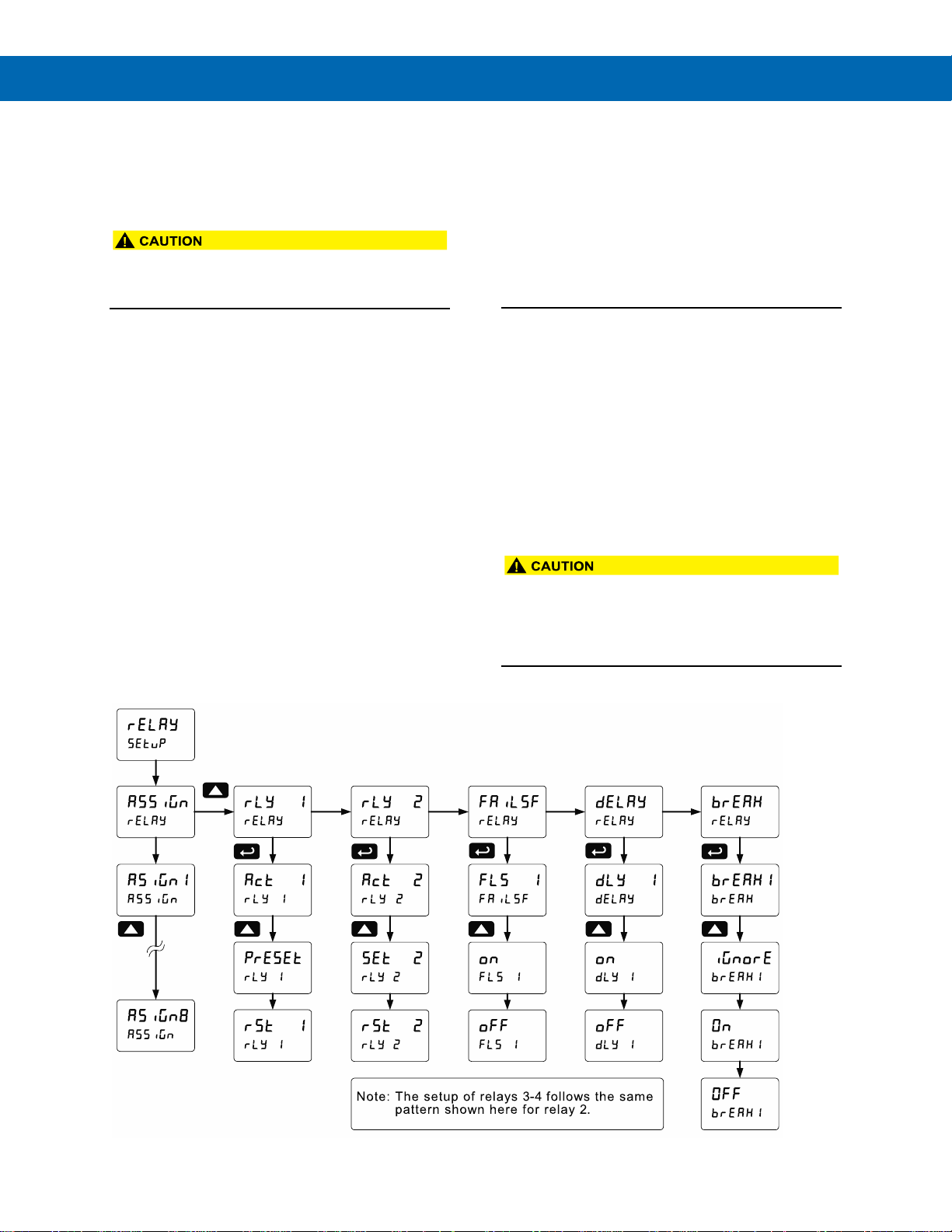
ProtEX-MAX PD8-6210 Explosion-Proof Analog Input Batch Controller
Instruction Manual
43
Setting the Relay Operation (relay)
This menu is used to set up the operation of the
relays.
• During setup, the relays do not follow the input
and they will remain in the state found prior to
entering the Relay menu.
1. Relay assignment
a. Rate for low and high alarm
b. Total for batch control relays
c. Grand total for grand total alarms
2. Relay action
a. Automatic reset only (non-latching)
b. Automatic + manual reset when not in a
batch process (non-latching)
c. Latching (manual reset when not in a
batch process only)
d. Latching with Clear (manual reset when
not in a batch process only after alarm
condition has cleared)
e. Pump alternation control (Not applicable
to batch control)
f. Sampling (the relay is activated for a
user-specified time and may be
assigned to rate or grand total)
g. Off (relay state can be controlled by
Interlock feature)
3. Set and reset points; batch preset
4. Fail-safe operation
a. On (enabled)
b. Off (disabled)
5. Time delay
a. On delay (0-999.9 seconds)
b. Off delay (0-999.9 seconds)
6. Relay action for loss (break) of 4-20 mA input
(ignore, on, off)
Note: Fail-safe should not be used for relays assigned to
batch control.
• The rate alarms are active only during a batch
process. As a result, rate alarms should not be
programmed with manual reset, as they cannot
be manually reset during a batch process, the
only time they are active.
Page 44
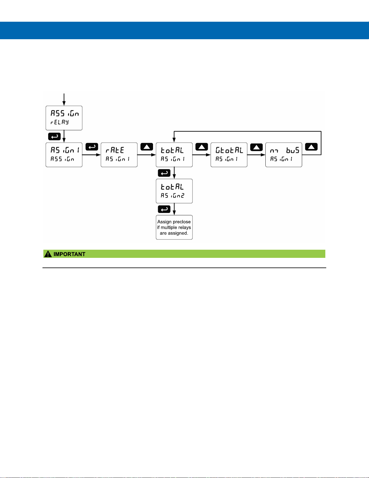
ProtEX-MAX PD8-6210 Explosion-Proof Analog Input Batch Controller
Instruction Manual
44
Relay Assignment (Assign)
The relays can be assigned to any of the following
parameters:
1. Rate for low or high alarm indication
2. Total for batch control relays
3. Grand total for alarm indication or sampling
• Relay 1 should always be assigned to “total” for batch control applications.
Page 45
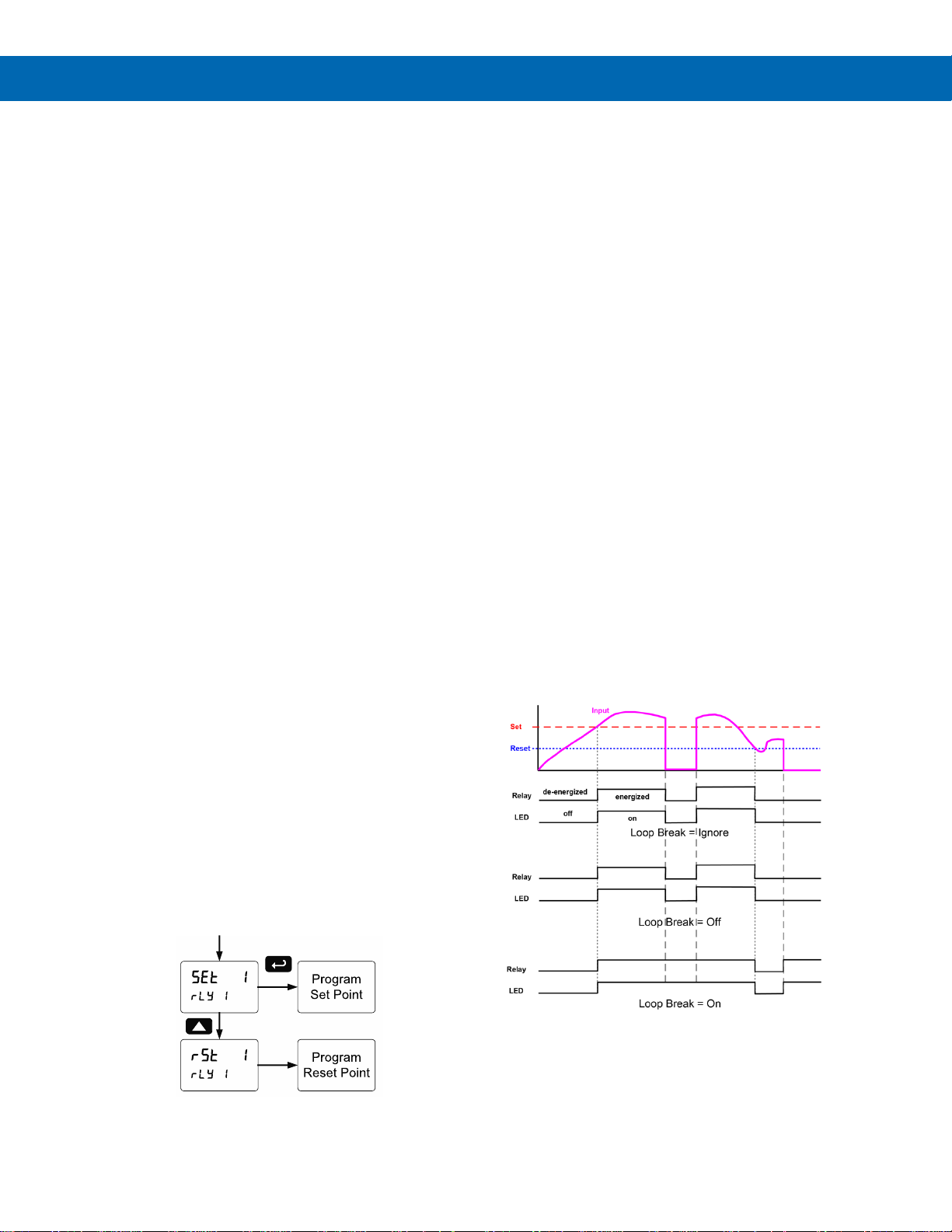
ProtEX-MAX PD8-6210 Explosion-Proof Analog Input Batch Controller
Instruction Manual
45
Setting the Relay Action
Operation of the relays is programmed in the Action
menu. The relays are commonly set up for any of the
following modes of operation:
1. Always set to Auto for Batch control operation.
Also for automatic reset (non-latching) of alarms.
2. Sampling (the relay is activated for a
user-specified time)
3. Off (relay state can be controlled by Interlock
feature)
In addition, the following relay actions may be
programmed. These actions are not appropriate for
batch control applications but may be used when the
controller is in other applications.
4. Automatic + manual reset when not in a batch
process (non-latching)
5. Latching (manual reset only, when not in a batch
process)
6. Latching with Clear (manual reset only when not
in a batch process after alarm condition has
cleared)
7. Pump alternation control (not applicable to batch
control)
Setting Batch Control Relays
Operation of batch control relays are programmed in
the Assign menu by selecting total as the assignment.
Relays set to total beyond the first relay will include a
pre-close parameter (precls) option. Selecting yes for
precls will enable multi-stage batching with pre-close,
and the valve will close prior to the end of the batch at
volume equal to the preset value minus the pre-close
amount entered. Selecting no for precls will have the
relay perform identically to the first batch control relay
set to total.
Programming Alarm Set and Reset Points
High alarm: program set point above reset point.
Low alarm: program set point below reset point.
The deadband is determined by the difference
between set and reset points. Minimum deadband is
one display count. If the set and reset points are
programmed with the same value, the relay will reset
one count below the set point.
Note: Changes are not saved until the reset point has been
accepted.
Setting Fail-Safe Operation
In fail-safe mode of operation, the relay coil is
energized when the process variable is within safe
limits and the relay coil is de-energized when the
alarm condition exists. The fail-safe operation is set
independently for each relay. Select on to enable or
select off to disable fail-safe operation. Failsafe
mode should not be used on batch relays assigned to
total.
Programming Time Delay
The On and Off time delays may be programmed for
each relay between 0 and 999.9 seconds. The relays
will transfer only after the condition has been
maintained for the corresponding time delay.
The On time delay is associated with the set point.
The Off time delay is associated with the reset point.
Relay Action for Loss of 4-20 mA Input (Loop Break)
The loop break feature is associated with the 4-20 mA
input. Rate alarm relays may be programmed to go to
one of the following conditions when the controller
detects the loss of the input signal (i.e. < 0.005 mA):
1. Turn On (Go to alarm condition)
2. Turn Off (Go to non-alarm condition)
3. Ignore (Process as a low signal condition)
Note: This is not a true loop break condition; if the signal
drops below 0.005 mA, it is interpreted as a “loop break”
condition.
Page 46
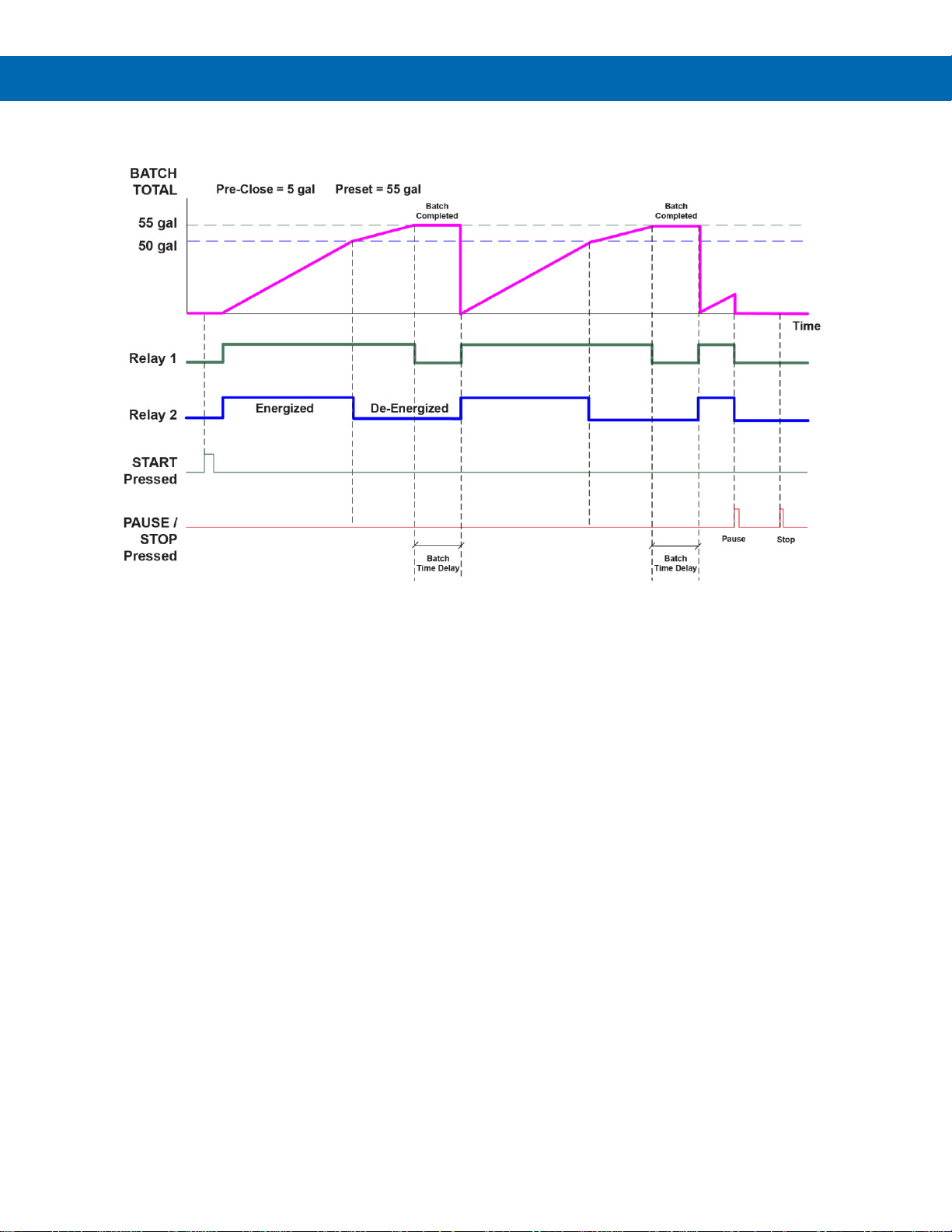
ProtEX-MAX PD8-6210 Explosion-Proof Analog Input Batch Controller
Instruction Manual
46
Automatic Batch Control Operation
The following graph shows automatic batch operation.
When START is pressed, a short delay occurs before the low flow alarm sensing is activated. Each relay can be
programmed with additional ON delay to satisfy various conditions and applications.
1. START button is pressed
2. Both relays are energized opening both valves controlling the flow
3. At 50 gallons (pre-close = 5 gal), relay 2 closes the main valve
4. At 55 gallons (preset = 55 gal), relay 1 closes the dribble valve
5. After the Batch Time Delay elapses, a new batch starts automatically without the operator’s intervention.
Page 47
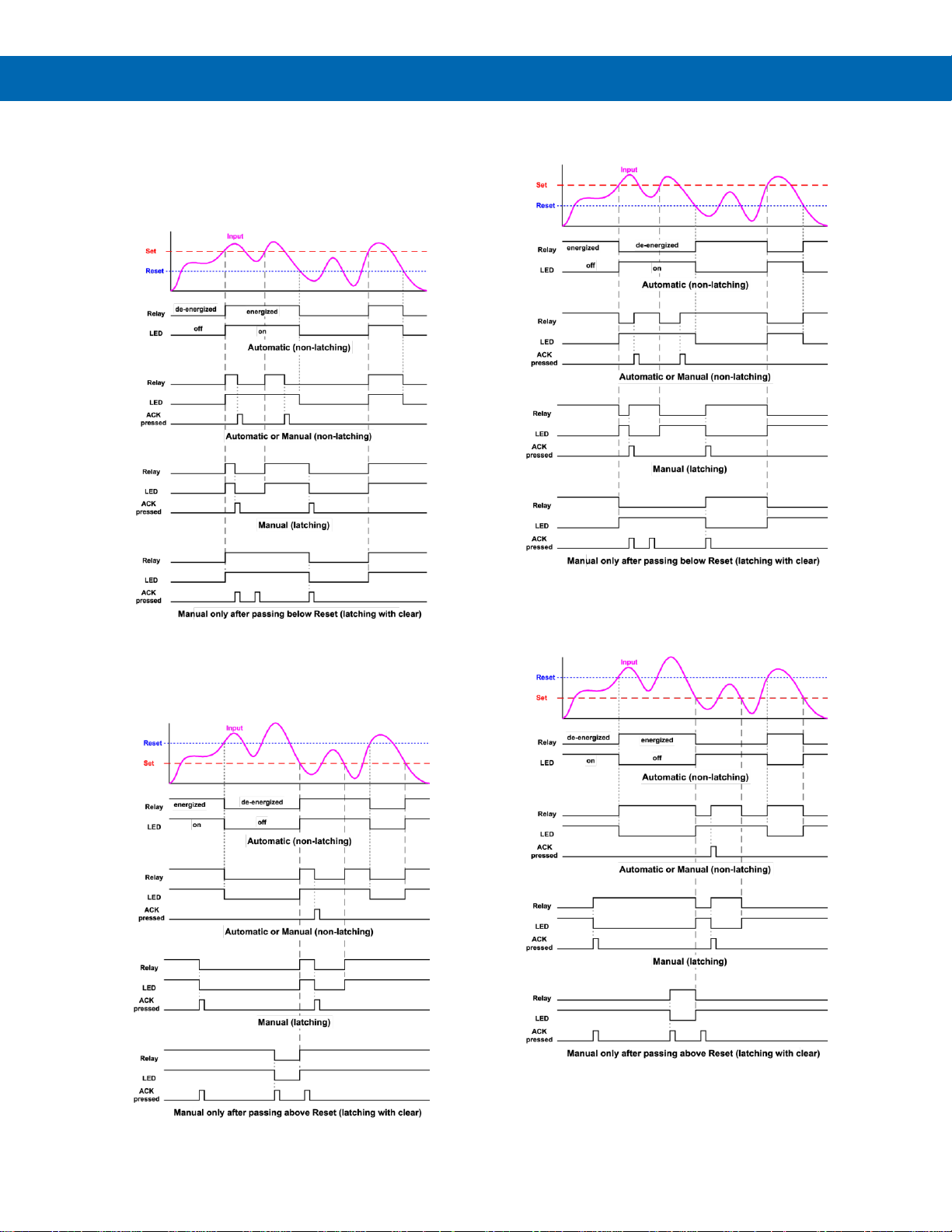
ProtEX-MAX PD8-6210 Explosion-Proof Analog Input Batch Controller
Instruction Manual
47
Relay and Alarm Operation Diagrams
The following graphs illustrate the operation of the
relays, status LEDs, and ACK button.
High Alarm Operation (Set > Reset)
For Manual reset mode, ACK can be pressed anytime
to turn "off" relay. To detect a new alarm condition, the
signal must go below the set point, and then go above
it.
Low Alarm Operation (Set < Reset)
For Manual reset mode, ACK can be pressed anytime to turn
"off" relay. To detect a new alarm condition, the signal must
go below the set point, and then go above it.
High Alarm with Fail-Safe Operation (Set > Reset)
Note: Relay coil is energized in non-alarm condition. In case
of power failure, relay will go to alarm state.
Low Alarm with Fail-Safe Operation (Set < Reset)
Note: Relay coil is energized in non-alarm condition. In case
of power failure, relay will go to alarm state.
Page 48
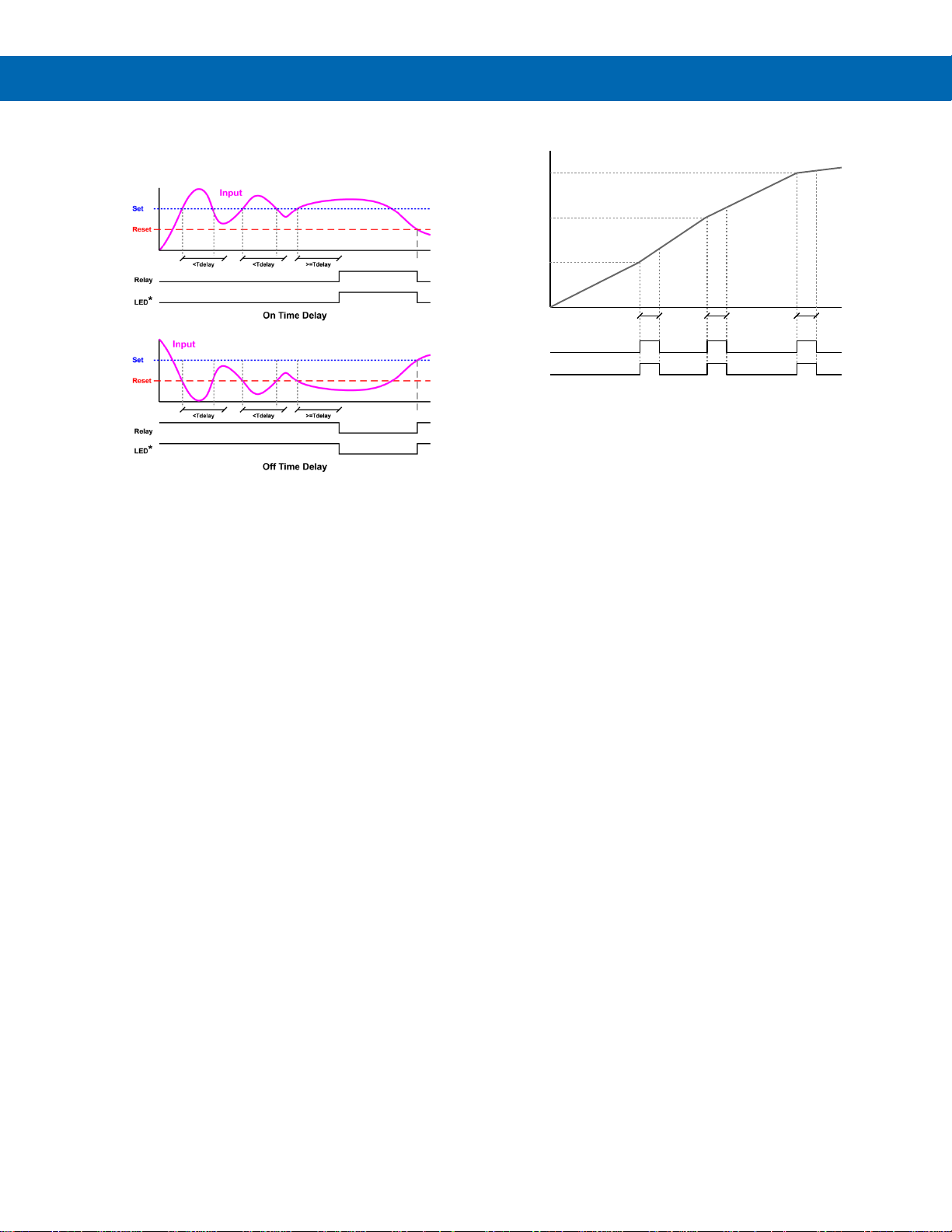
ProtEX-MAX PD8-6210 Explosion-Proof Analog Input Batch Controller
Instruction Manual
48
Time Delay Operation
The following graphs show the operation of the time
delay function.
When the signal crosses the set point, the On time
delay timer starts and the relay trips when the time
delay has elapsed. If the signal drops below the set
point (high alarm) before the time delay has elapsed,
the On time delay timer resets and the relay does not
change state. The same principle applies to the Off
time delay.
Note: If “Automatic or Manual (A-nmAn)” reset mode is
selected, the LED follows the reset point and not the relay
state when the relay is acknowledged.
Total Relay Sampling Operation
When the total reaches the preset, the relay trips and
the sample time starts. After the sample time has
elapsed, the relay resets. The cycle repeats every time
the preset value is added to the total.
Preset = 100
100
Relay
LED
Total
200
300
Sample
Time
Sample
Time
Sample
Time
Page 49
ProtEX-MAX PD8-6210 Explosion-Proof Analog Input Batch Controller
Instruction Manual
49
Relay Operation Details
Overview
The relays of the controller can serve three roles, as
batch control relays for single or multi-stage batching,
as rate or grand total alarm, or as a sampling relay
based on grand total or rate alarm.
These capabilities include front panel alarm status
LEDs and 4 relays.
The relays used for batch control (total) are activated
when the batching process starts and deactivate when
the batch total is reached. The relays assigned as
pre-close are deactivated when the batch reaches the
preset value minus the pre-close value.
For an example of batch control operation, see Batch
Control Operation Example on page 54.
Typical applications for alarms are low flow and high
flow alarms or grand total limit alarms. Note that rate
alarms are only activated during a batch process and
deactivated when the process is stopped.
The relays can also be set for sampling, where the
relay will activate for a specific amount of time after a
certain grand total has been reached (e.g. 10 seconds
sample relay activation every 100 gallons batched).
There are three basic ways the relays can be used:
1. Batch Control (Total)
2. High or Low Alarms for Rate or Grand Total
3. Sampling (Based on Grand Total and Sample
Time)
Relays Initialization
Batch control (total) relays will activate when the start
function is enabled, such as when the START button
is pressed. Rate alarm relays will enable and initialize
to their programmed states when the batch process is
started. Grand total alarm relays will initialize to their
programmed state at controller power-up.
Fail-Safe Operation
The following table indicates how alarm relays behave
based on the fail-safe selection for each relay:
Fail-Safe
Selection
Non-Alarm
State
Alarm State
Power Failure
NO
NC
NO
NC
Off
Open
Closed
Closed
Open
Relays in
de-energized state
On
Closed
Open
Open
Closed
Relays in energized
state
Note: NO = Normally Open, NC = Normally Closed. This
refers to the condition of the relay contacts when the power
to the controller is off.
Front Panel LEDs
The alarm status LEDs on the front panel are available
on all controllers and provide status indication for the
following:
LED
Status
1
Batch Relay 1
2
Batch Relay 2
3
Low Flow Alarm
4
High Flow Alarm
The controller is supplied with alarm points that
include front panel LEDs to indicate alarm conditions.
This standard feature is particularly useful for alarm
applications that require visual-only indication. The
LEDs are controlled by the set and reset points
programmed by the user. When the display reaches a
set point for a high or low alarm, the corresponding
alarm LED will turn on. When the display returns to the
reset point the LED will go off. Note that rate alarms
are only activated during a batch process, and they
are deactivated when the process is stopped.
Latching relays, or relays with manual reset, are not
recommended when using this controller for batch
control, as the manual reset will not be acknowledged
during a batch process, when the rate alarms are
active. For information on latching and manual reset
alarms, see the PD8-6200 instruction manual.
Automatic Reset (Auto)
In this application, the controller is set up for automatic
reset (non-latching relay). Acknowledging the alarm
while it is still present has no effect on either the LED
or the relay. When the alarm finally goes away, the
relay automatically resets, and the LED also goes off.
Pump Alternation Control
Pump alternation control is not recommended when
using this controller for batch control, as it is used only
in level applications, and not with rate, total, or
batching applications.
Automatic reset only
Condition
LED
Relay
Normal
Off
Off
Alarm
On
On
Ack (No effect)
On
On
Normal
Off
Off
Page 50
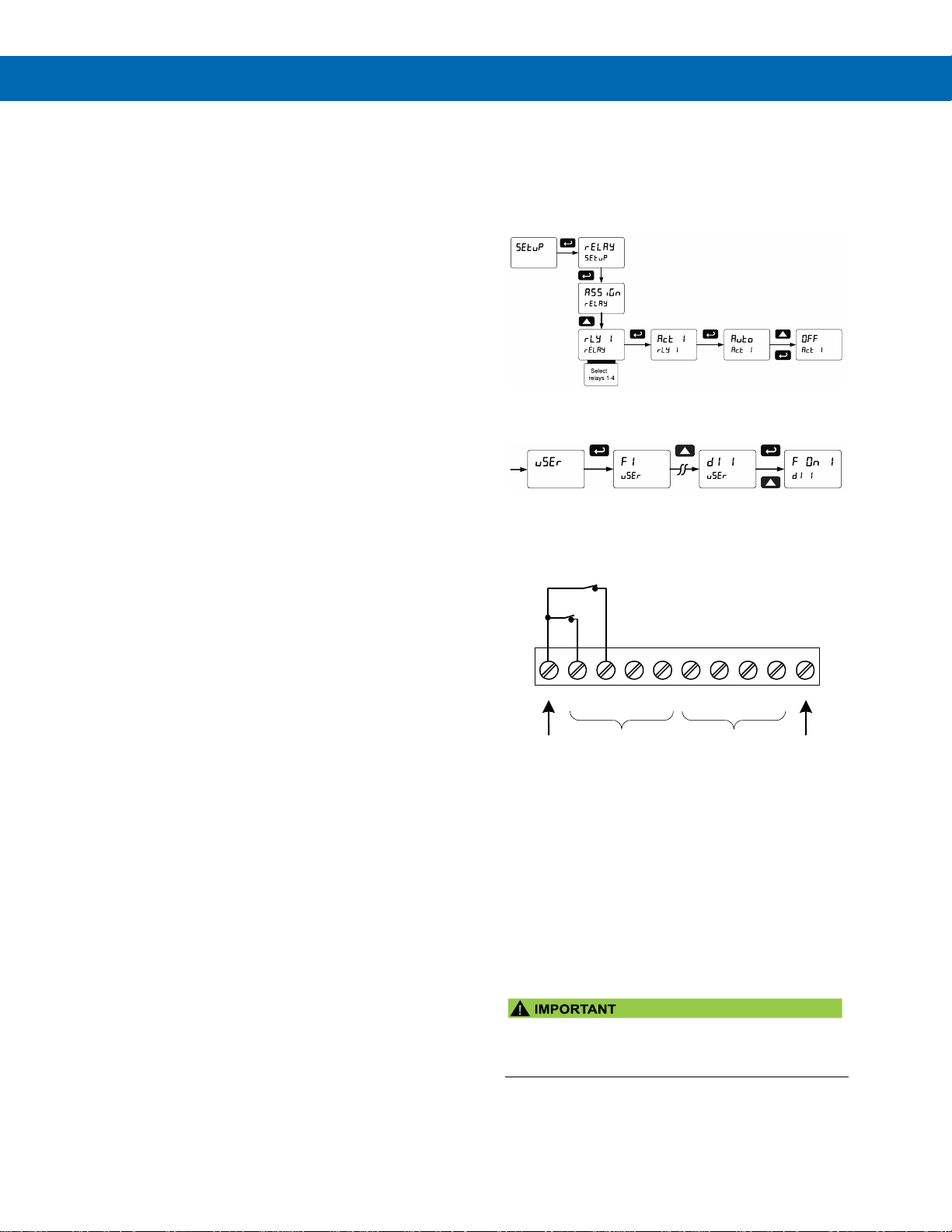
ProtEX-MAX PD8-6210 Explosion-Proof Analog Input Batch Controller
Instruction Manual
50
Sample Relay Operation
The sampling function allows the operator to set a set
point for a “sampling” relay. This can be done for the
rate, total, or grand total. Each time the relay reaches
the set point, it will close that relay’s contacts for a
programmed period set by the user.
A rate sampling relay will activate for the sample time
(sanm t), every time the set point rate is reached.
A total sampling relay will activate for the sample time
(sanm t), every time the process has batched the
amount programmed for the set point (See the
diagrams on page 48 more details). The utility of this
function can, of course, be expanded beyond sampling
and be used whenever a timed relay output closure is
required after the batch total interval reaches a certain
set point.
Setting Up the Interlock Relay (Force On) Feature
Relays 1-4 can be set up as interlock relays. To set up
the relays for the interlock feature:
1. Access the Setup – Relay – Action menu and set
the action to off.
2. In the Advanced features – User menu program
any of the digital inputs to Force On any of the
internal relays (1-4).
3. Connect a switch or dry contact between the +5 V
terminal and the corresponding digital input (dI-1 to
dI-4) terminal.
Interlock Relay Operation Example
Relays 3 & 4 are configured to energize (their front
panel LEDs are steady on) when SW1 & SW2
switches (above) are closed. If the contacts to these
digital inputs are opened, the corresponding front
panel LEDs flash indicating this condition. The
processes being controlled by the interlock relay will
stop, and will re-start only after the interlock relay is reactivated by the digital inputs (switches).
Note: If multiple digital inputs are assigned to the same relay,
then the corresponding logic is (AND) – i.e. both switches
must be closed to activate the relay.
• If the digital inputs are assigned to the Interlock
Function, then they cannot be used to program
the controller remotely.
1 2 3 4 5
6
+5
I1
I2
I3
I4
O1
7
8
O2
O3
9
10
O4
G
DI 1-4
DO 1-4
5 VDC
GND
SW2
SW1
Page 51
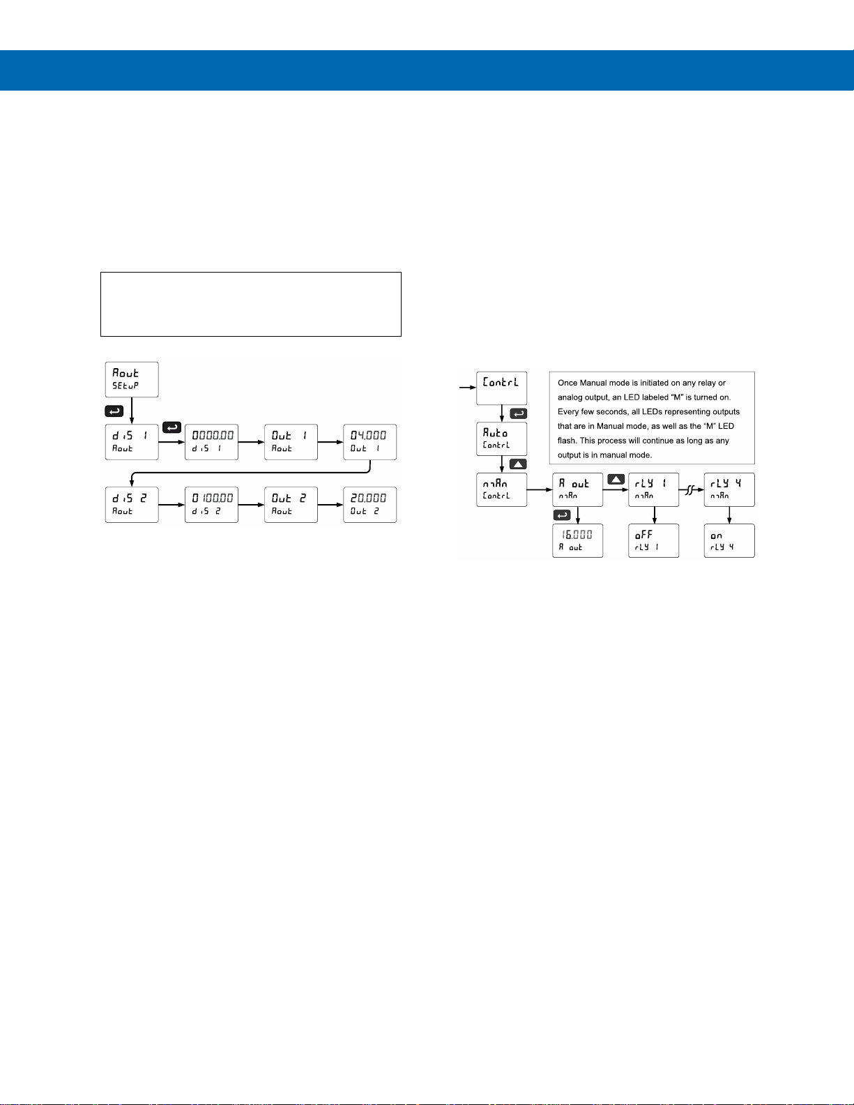
ProtEX-MAX PD8-6210 Explosion-Proof Analog Input Batch Controller
Instruction Manual
51
Scaling the 4-20 mA Analog Output (Aout)
The 4-20 mA analog output can be scaled to provide a
4-20 mA signal for any rate display range selected.
No equipment is needed to scale the analog output;
simply program the display values to the
corresponding mA output signal.
The Analog Output menu is used to program the
4-20 mA output based on rate display values.
For further details, see Setting Numeric Values
on page 37, Analog Output Value for Loss of 4-
20 mA Input (Loop Break) on page 63.
Reset Menu (reset)
The Reset menu is used to reset the total, grand
totals, batch count, maximum, or minimum reading
(peak or valley) reached by the process; both
maximum and minimum may be reset at the same
time by selecting “reset high & low” (rst HL).
Manual Control Menu (Contrl)
The Manual Control menu is used to control the
4-20 mA analog output and the relays manually,
ignoring the input. Each relay and analog output can
be programmed independently for manual control.
Selecting automatic control sets all relays and analog
output for automatic operation.
Page 52
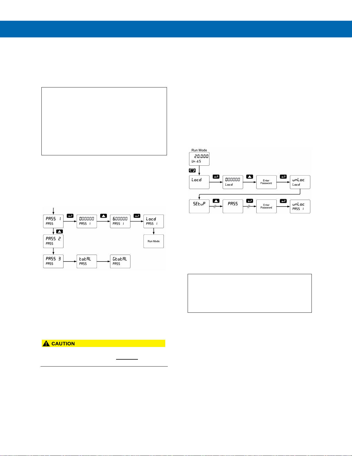
ProtEX-MAX PD8-6210 Explosion-Proof Analog Input Batch Controller
Instruction Manual
52
Setting Up the Password (pass)
The Password menu is used for programming three
levels of security to prevent unauthorized changes to
the programmed parameter settings and to program
the non-resettable totalizer.
Pass 1: Allows use of function keys and digital
inputs
Pass 2: Allows use of function keys, digital inputs
and editing set/reset points
Pass 3: Restricts all programming, function keys,
and digital inputs.
Total Password: Prevents resetting the total
manually
Gtotal Password: Prevents resetting the grand total
manually
Protecting or Locking the Controller
Enter the Password menu and program a six-digit
password.
For instructions on how to program numeric values
see Setting Numeric Values, page 37.
Grand Total Reset Password & Non-Resettable Total
The grand total can be password-protected to prevent
unauthorized total resets.
The grand total can be programmed as a
non-resettable total by entering the password
“050873”.
• Once the Grand Total has been programmed as
“non-resettable” the feature CANNOT be
disabled.
Making Changes to a Password Protected Controller
If the controller is password protected, the controller
will display the message Locd (Locked) when the
Menu button is pressed. Press the Enter button while
the message is being displayed and enter the correct
password to gain access the menu. After exiting the
programming mode, the controller returns to its
password protected condition.
Disabling Password Protection
To disable the password protection, access the
Password menu and enter the correct password twice,
as shown below. The controller is now unprotected
until a new password is entered.
If the correct six-digit password is entered, the
controller displays the message unLoc (unlocked) and
the protection is disabled until a new password is
programmed.
If the password entered is incorrect, the controller
displays the message Locd (Locked) for about two
seconds, and then it returns to Run Mode. To try
again, press Enter while the Locked message is
displayed.
Did you forget the password?
The password may be disabled by entering a
master password once. If you are authorized to
make changes, enter the master password 508655
to unlock the controller.
Page 53
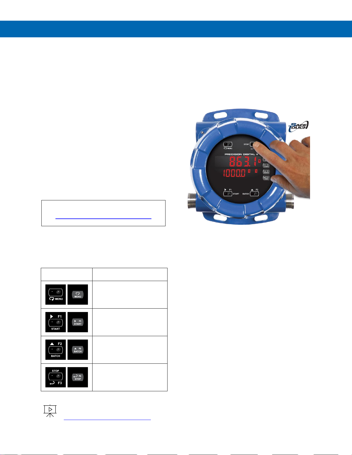
ProtEX-MAX PD8-6210 Explosion-Proof Analog Input Batch Controller
Instruction Manual
53
Controller Operation
When installed, the primary way to operate the
controller is with the SafeTouch through-glass buttons
that allow the user to perform various operations
without removing the cover and exposing the
electronics to the hazardous environment. The user
can also operate the controller by connecting a
hazardous area-approved control station or switch to
one of the digital inputs. These can be used to perform
various operations on the controller based on the
Programmable Function Keys. Finally, certain
operations can be performed on the controller with
MeterView Pro software or through Modbus
commands.
The three default operations that can be performed
with the controller’s SafeTouch buttons are:
1. Set the batch size
2. Start the batch
3. Pause/Stop the batch
In addition, the user can program the SafeTouch
Buttons to perform a variety of useful operations by
reassigning them to other functions per Function Keys
& Digital I/O Available Settings on page 64.
Watch Batch Control Video at
www.predig.com/videos/KN6Y6R0I1OE
Button Operation
The following table shows the default operations for
the F1, F2, and F3 SafeTouch Buttons: setting the
batch size, starting the batch, and stopping the batch.
Button Symbol
Description
Press to enter or exit
Programming Mode or view
settings
Press to start the batch or
other function assigned
through the User menu
Press to set the batch size or
other function assigned
through the User menu
Press to pause/stop the batch
or other function assigned
through the User menu
To learn more about SafeTouch buttons,
see this video:
predig.com/videos/Safetouch_Buttons
SafeTouch Buttons
The ProtEX-MAX is equipped with four sensors that
operate as through-glass buttons so that it can be
programmed and operated without removing the cover
(and exposing the electronics) in a hazardous area.
These buttons can be disabled for security by
selecting DISABLE on the switch labeled
NO-CONTACT BUTTONS located on the
connector board.
To actuate a button, press one finger to the glass
directly over the marked button area. Then retract
finger more than three inches from the glass before
pressing the next button. When the cover is removed,
the four mechanical buttons located next to the
sensors are used. The sensors are disabled when a
mechanical button is pressed and will automatically be
re-enabled after 60 seconds of inactivity.
The SafeTouch Buttons are designed to filter normal
levels of ambient interference and to protect against
false triggering, however, it is recommended that the
SafeTouch Buttons be disabled (slide switch to
DISABLE) if there is an infrared interference source in
line-of-sight to the display.
The SafeTouch Buttons are configured by default to
duplicate the function of the front panel mechanical
pushbuttons associated with the integrated controller.
The symbols by each SafeTouch button correspond to
a mechanical button as shown in the table to the left.
SafeTouch Button Tips:
• To the extent possible, install the display facing
away from sunlight, windows, reflective objects
and any sources of infrared interference.
• Keep the glass window clean.
• Tighten the cover securely.
• Use a password to prevent tampering.
Default Batch Control Operation
The following describes the operation of the three front
panel operating keys as programmed with default
settings.
Page 54
ProtEX-MAX PD8-6210 Explosion-Proof Analog Input Batch Controller
Instruction Manual
54
START Button
Press the START button to begin a new batch
process. Press the START button to resume a batch
that has been stopped.
BATCH Button
Press the Batch button to access the Preset (batch
amount) menu. Program the batch with the arrow
keys, and confirm with the Enter key.
STOP Button
Press the STOP key once during a batch to pause.
Press the STOP key while paused to stop and cancel
the batch. Press the STOP key while in stop/ready
mode to cycle the second display parameters: preset,
grand total, and batch count (or other parameter
assigned to the second display).
• Only STOP Button Enabled if a Batch is
Running. During a batch process, only the
pause/stop functions are operational, other
buttons are deactivated.
Batch Control Operation Example
The following example shows how two-stage batch
control functions with a PD8-6210. This setup will
establish a 55 gallon preset for the batch, with a main
valve (high flow) that will close at 50 gallons, and a
trickle valve (low or restricted flow) that will close at 55
gallons. After the batch, the next container will hold 80
gallons, so the preset will be changed to 80.
Two-Stage Batch Control Setup Using Relays 1 & 2
The following table shows the parameters as they
appear within the Setup menu entry relay.
Parameter
Setting
Function
Relay
Assign
Press Enter to enter the relay
assignment parameters.
Asign1
total
Assign relay 1 to batch total
control.
Asign2
total
Assign relay 2 to batch total
control.
Precls
Total
Press Enter to access
pre-close selection for
multi-stage control.
Precls
Yes
Yes, to enable a pre-close
value for relay 2.
Yes
00005..0
Set the pre-close value to 5 for
closing the valve controlling
relay 2 five gallons before
reaching the preset.
…
Assignment for relays 3-4.
Rly 1
relay
Select relay 1 setup.
Act 1
rly 1
Configure activation of relay 1.
Act 1
Auto
Always set to Auto for batch
control function.
Rly 1
Preset
Set the preset value for batch
control.
Preset
00055.0
Set 55 gallons as the preset.
…
Setup for relays 3-4.
The operation of relay 2 has already been assigned for
multi-stage control pre-close and will not appear as a
selection in the relay menu.
If only single stage batch control with one relay for
control is desired, set the assignment of relay 2,
assign2, to off, rate, or grand total.
The following pages show an illustration of how the
above settings control the batch operation. The display
assignment shown is the default.
Page 55
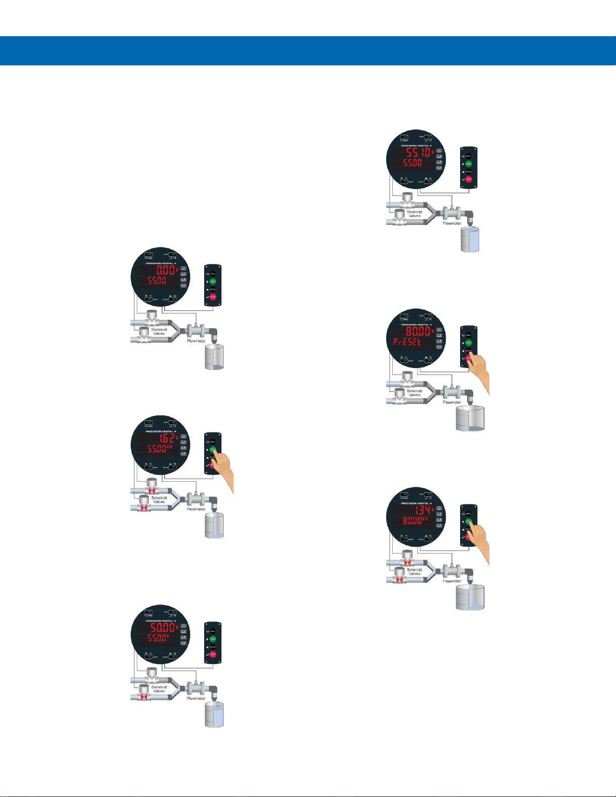
ProtEX-MAX PD8-6210 Explosion-Proof Analog Input Batch Controller
Instruction Manual
55
Manual Batch Control
The manual batch control feature is used for batch
processes where each batch must be started by the
operator. The following diagrams demonstrate a
typical manual batch operation with an optional
hazardous area-approved remote control station. The
batch could also be controlled using the through-glass
buttons on the controller.
Manual Batch Control Operation
1. System Setup
Both valves are closed with an empty barrel
in place. The batched total is displayed in the
main display, the preset is selected for the
second display.
2. Batch Start
The START button is pressed. Both valves
open. The barrel begins to fill.
3. Preclose Valve
When the batch total reaches a value of
50.00 (Preset [55.00] – Pre-close [5.00]) the
full-flow valve closes. The fill rate of the tank
slows as a result.
4. Completed Batch
When the batch is complete, the restricted-flow
valve closes. If overrun occurs, then the next
batch will adjust for this offset amount to
maintain accuracy.
5. Change Preset
After placing a new, empty barrel, a new
preset fill amount may be selected with the
Batch key, while the process is stopped.
6. Begin New Batch
The new batch begins when the START
button is pressed, causing both relays to
activate and both valves to open.
Page 56
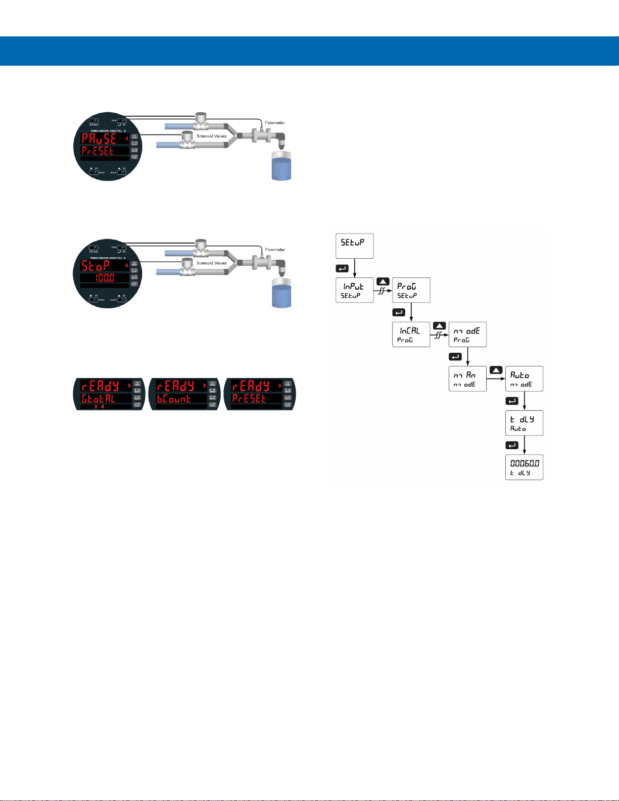
ProtEX-MAX PD8-6210 Explosion-Proof Analog Input Batch Controller
Instruction Manual
56
Additional Features
Pause Batch
At any time during the batch, the STOP button may be
pressed to pause the process.
Stop Batch
When paused, pressing the START button will
continue the batch, and pressing the STOP button
again will cancel the batch.
STOP Mode
When in STOP mode, the STOP button may be
pressed to cycle through alternative parameters to be
displayed on the second display, including the grand
total, batch count, and preset.
Reset
The grand total and batch count may be reset in the
reset menu by pressing the MENU button and
entering the reset menu. It may also be reset with
digital inputs.
Automatic Batch Control
The automatic batch control feature is used for batch
processes where the batch size does not change, or
the operator wants the next batch to start
automatically after the previous batch is complete. The
following diagrams demonstrate a typical automatic
batch operation.
Setup for Automatic Batch Control
The batch controller can be configured to
automatically start a new batch after the selected time
delay between batches has elapsed.
The time delay allows time for removing the full barrel
and putting an empty barrel in place. Once the
process starts, the operator does not have to press
any buttons; except to pause or stop the batch
process.
Page 57
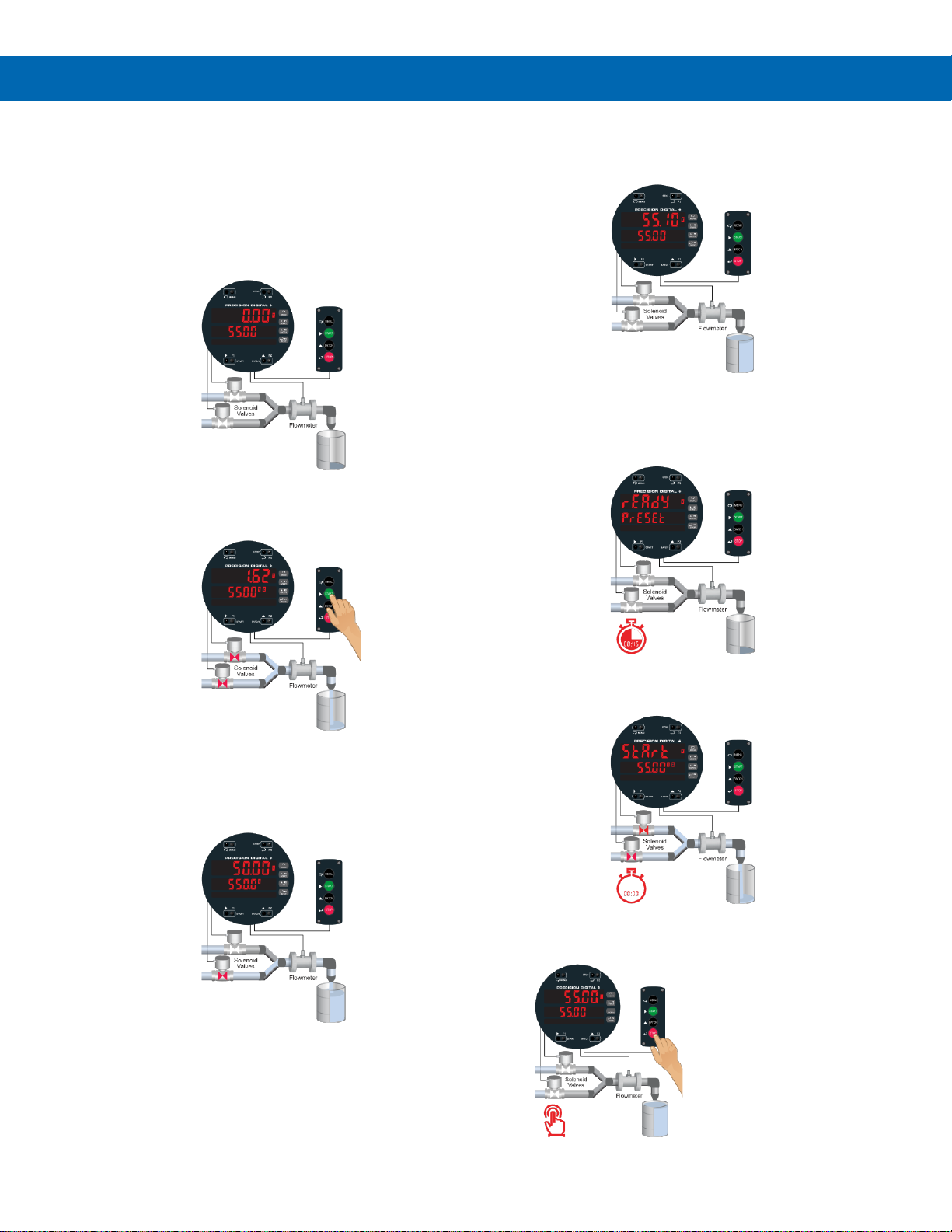
ProtEX-MAX PD8-6210 Explosion-Proof Analog Input Batch Controller
Instruction Manual
57
Automatic Batch Control
Operation
1. System Setup
Both valves are closed with an empty barrel
in place. The batched total is displayed in the
main display, the preset is selected for the
second display. The batch could also be
controlled using the through-glass buttons on
the controller.
2. Batch Start
The START button is pressed. Both valves
open. The barrel begins to fill.
3. Preclose Valve
When the batch total reaches a value of
50.00 (Preset [55.00] – Pre-close [5.00]) the
full-flow valve closes. The fill rate of the tank
slows as a result.
4. Completed Batch
When the batch is complete, the restricted-flow valve
closes. If overrun occurs, then the next batch will
adjust for this offset amount to maintain accuracy.
5. Replace Full Barrel with Empty Barrel
After the batch is completed, the operator removes
the full barrel and places an empty barrel; the new
batch starts automatically after a user-defined
time delay of 60 seconds (Time Delay).
6. Begin New Batch
The new batch begins automatically after 60 seconds,
both relays activate and both valves open.
7. Stop Batch
At the end of the shift, press STOP twice to stop
the batch process.
Page 58
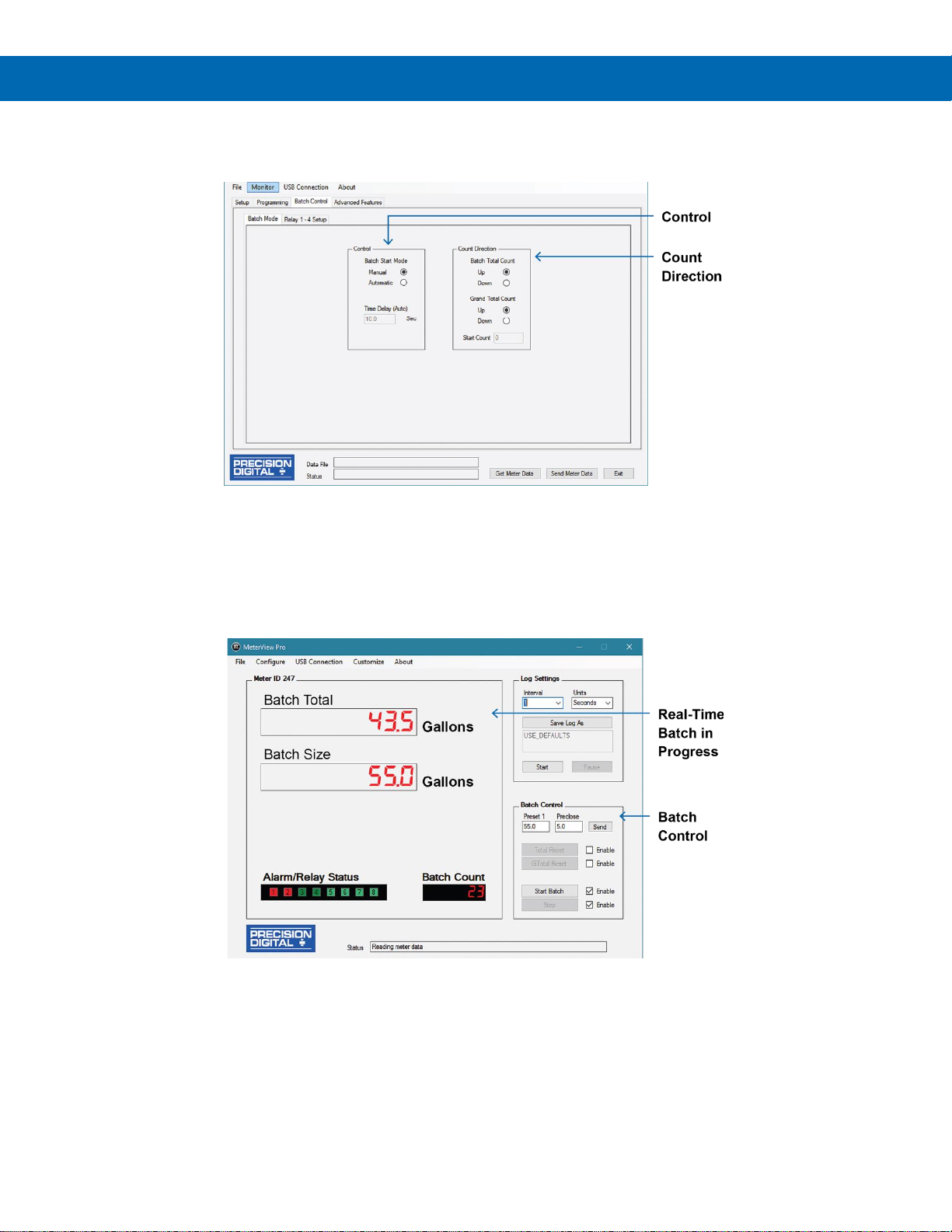
ProtEX-MAX PD8-6210 Explosion-Proof Analog Input Batch Controller
Instruction Manual
58
Setup with MeterView Pro
Use MeterView Pro software to set up the batch controller for manual or automatic batch control, count up or count
down operation, and set the batch preset and pre-close values.
Control
Program for automatic or manual batch operation and
set time delay if automatic mode.
Count Direction
Program the batch controller to count up or count down
and set a starting count value if desired.
Operate with MeterView Pro
MeterView Pro software also shows the Batch Size and Current Batch Total as well as allowing the user to start and
stop the batch.
Real-Time Batch in Progress
MeterView Pro software shows all the important
batch-control information.
Batch Control
MeterView Pro allows the user to set preset 1 and
preclose values and start and stop the batch
Page 59
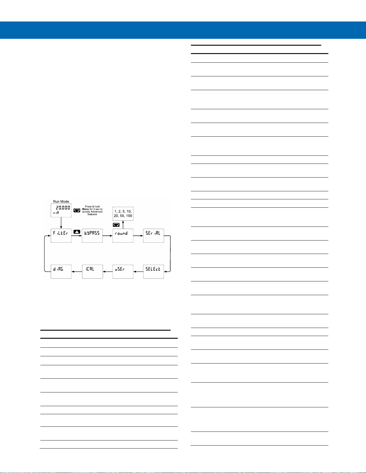
ProtEX-MAX PD8-6210 Explosion-Proof Analog Input Batch Controller
Instruction Manual
59
Advanced Setup &
Programming
In addition to the functions described in Controller
Operation on page 53, the following advanced
operation and display features may be programmed.
Please note that configuring these features may
disable some default batch controller features or it
can make running a batch operation impossible.
These functions should only be used by users who
are sure of their need in their application.
Advanced Features Menu
To simplify the setup process, functions not needed
for most applications are located in the Advanced
Features menu.
Press and hold the Menu button for three seconds to
access the advanced features of the controller. This
cannot be done during a batch process as all
functions other than STOP are disabled during a
batch process, including the Menu button.
Advanced Features Menu & Display Messages
The following table shows the functions and
messages of the Advanced Features menu in the
order they appear in the menu.
Advanced Features Menu & Display Messages
Display
Parameter
Action/Setting
filter
Filter
Set noise filter value
bypASs
Bypass
Set filter bypass value
Round
Round
Set the rounding value for
display variables
seriAl
Serial
Set serial communication
parameters
SlaVId
Slave ID
Set slave ID or controller
address
baud
Baud rate
Select baud rate
Tr dLY
Transmit
delay
Set transmit delay for serial
communication
Parity
Parity
Select parity Even, Odd, or
None with 1 or 2 stop bits
t-byt
Time byte
Set byte-to-byte timeout
Advanced Features Menu & Display Messages
Display
Parameter
Action/Setting
SelEct
Select
Enter the Select menu
(function, cutoff, out)
Functn
Input Signal
Conditioning
Select linear, square root,
or programmable exponent
Linear
Linear
Set controller for linear
function and select number
of linearization points
No PtS
Number of
points
Set controller for 2 to
32-point linearization
Square
Square root
Set controller for square
root extraction
Prog E
Programmable
exponent
Set controller for
programmable exponent
and enter exponent value
CutofF
Cutoff
Set low-flow cutoff
Count
Count
Set the totals to count up
or down from a set value
Tot C
Total count
Set the batch to count up
to or down from the preset
up
Up
Set the total to count up
Douwn
Down
Set the total to count down
Gtot C
Grand total
count
Set the grand total to count
up or down from a defined
value
C strt
Count start
Set the starting grand total
value when counting down
AoutPr
Analog output
programming
Program analog output
parameters
Source
Source
Select source for the
4-20 mA output
O-rang
Overrange
Program mA output for
display overrange
u-rang
Underrange
Program mA output for
display underrange
Break
Loop Break
Set analog output value if
input loop break is
detected
Force
Force output
Force analog output value
for loop break
Ignore
Ignore
Ignore loop break condition
nmAx
Maximum
Program maximum mA
output allowed
nmin
Minimum
Program minimum mA
output allowed
Calib
Calibrate
Calibrate 4-20 mA output
(internal reference source
used for scaling the output)
4 nmA
4 mA output
Enter mA output value
read by milliamp meter
with at least 0.001 mA
resolution
20 nmA
20 mA output
Enter mA output value
read by milliamp meter
with at least 0.001 mA
resolution
user
User I/O
Assign function keys and
digital I/O
Page 60
ProtEX-MAX PD8-6210 Explosion-Proof Analog Input Batch Controller
Instruction Manual
60
Advanced Features Menu & Display Messages
Display
Parameter
Action/Setting
F1
F1 function key
Assign F1 function key
F2
F2 function key
Assign F2 function key
F3
F3 function key
Assign F3 function key
F4
F4 function
Assign F4 function (digital
input)
dI I
Digital input 1
Assign digital input 1 – 4
dO 1
Digital output 1
Assign digital output 1 – 4
ICal
Internal source
calibration
Enter internal source
calibration (used for
scaling the controller
without a signal source)
C CAL
Current
calibration
Calibrate 4-20 mA current
input (internal reference
source used for scaling the
input)
C lo
Current low
Calibrate low current input
(e.g. 4 mA)
C Hi
Current high
Calibrate high current input
(e.g. 20 mA)
V CAL
Voltage
calibration
Calibrate voltage input
V Lo
Voltage low
Calibrate low voltage input
(e.g. 0 V)
V Hi
Voltage high
Calibrate high voltage input
(e.g. 10 V)
Diag
Diagnostics
Display parameter settings
LED t
LED test
Test all LEDs
Info
Information
Display software number
and version
erase
Erase
Erase MeterView Pro
software stored in
controller’s memory
Function Keys Operation
During operation, the programmable function keys
operate according to the way they have been
programmed in the Advanced Features – User menu.
See Programmable Function Keys User Menu (user)
on page 64 for details. The following table shows the
default setting for each of the function keys.
Function
Key/Button
Default
Setting
Action
F1/START
Start
Start batch
F2/BATCH
preset
Change preset
F3/STOP
stop
Pause/stop
batch
F4/Digital Input
Srtstp
Start/stop batch
Digital Inputs Operation
Five (5) digital inputs, F4, DI-1 to DI-4, come standard
on the controller. These digital inputs are programmed
identically to function keys F1, F2, and F3. The inputs
are triggered with a contact closure to +5 V in the case
of digital inputs 1-4 or with an active high signal, see
Digital I/O Connections on page 31 for details. The F4
is triggered with a contact closure to COM or with an
active low signal. During operation, digital inputs
operate according to the way they are programmed in
the Advanced Features – User menu. See
Programmable Function Keys User Menu (user) on
page 64 for details.
• Only STOP Operation Enabled if a Batch is
Running. During a batch process, the only
function that can be performed is the pause/stop
functions of the STOP button; the default
programming of the F3 key. No other functions,
including min/max display, manual alarm reset, or
total reset, will function while a batch is running.
Page 61
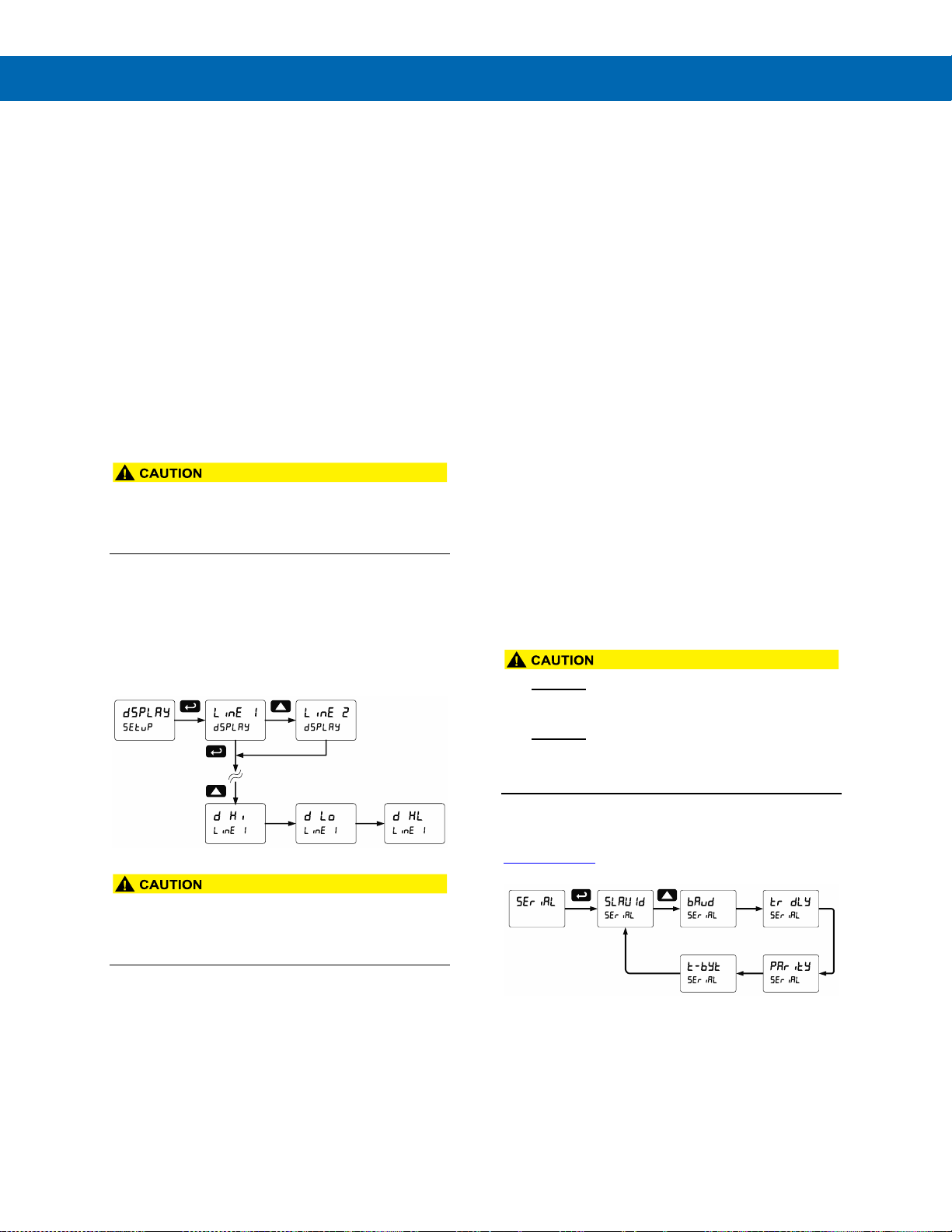
ProtEX-MAX PD8-6210 Explosion-Proof Analog Input Batch Controller
Instruction Manual
61
Advanced Setup and Calibration
Multi-Point Calibration & Scaling
The controller is set up at the factory for 2-point linear
calibration. The number of points for multi-point
calibration/scaling is set up in the Advanced Features
menu. Up to 32 linearization points may be selected.
See Multi-Point Linearization (Linear) on page 62 for
details.
Maximum/Minimum Readings
The max & min readings (peak & valley) reached by
the process can be displayed either continuously or
momentary:
1. Display briefly by assigning to the digital inputs in
the User menu.
2. Display continuously by assigning either display
to max/min through the Display menu.
• Changing the programming of the F1-F3 function
keys will disable the default batch operation of
these keys, and is not recommended for batch
control applications.
Any of the digital inputs can be programmed to reset
the max & min readings.
To display max/min readings continuously:
Assign either display to Max (d Hi), Min (d Lo),
or toggle between Max and Min (d HL) every
10 seconds.
• Note that changing the default programming of
the main or second displays may affect viewing
the batch total (main display) or preset (second
display) of the batch process.
Noise Filter (filter)
The noise filter is available for unusually noisy signals
that cause an unstable process variable display. The
noise filter averages the input signal over a certain
period. The filter level determines the length of time
over which the signal is averaged. The filter level can
be set between 2 and 199. The higher the filter level,
the longer the averaging time and so the longer it
takes the display to settle to its final value. Setting the
filter level to zero disables the filter function.
Noise Filter Bypass (bypass)
The noise filter bypass changes the behavior of the
controller so that small variations in the signal are
filtered out but large abrupt changes in the input
signal are displayed immediately. The bypass value
determines the minimum amount of signal change to
be displayed immediately. All signal changes smaller
than the bypass value are filtered or averaged by the
controller. The noise filter bypass may be set between
0.1 and 99.9% of full scale.
Rounding Feature (round)
The rounding feature is used to give the user a
steadier display with fluctuating signals. Rounding is
used in addition to the filter function.
Rounding causes the display to round to the nearest
value according to the rounding selected.
Modbus RTU Serial Communications (serial)
The controller is equipped with serial communications
capability as a standard feature using Modbus RTU
Serial Communication Protocol.
The controller may be connected to a PC for initial
configuration via the on-board USB connection. For
ongoing digital communications with a computer or
other data terminal equipment, use the RS-485
connection with the appropriate serial converter; see
Ordering Information on page 7 for details.
• DO NOT connect any equipment to the RJ45
M-LINK connector. Otherwise damage will occur
to the equipment and the controller.
• DO NOT disconnect the RJ45 connector located
to the left of the power terminal block. Doing so
will disable the on-board digital I/O, and the
RS-485 serial communications.
Notes: More detailed instructions are provided with each
optional serial communications adapter.
Refer to the ProtEX-MAX Modbus Register Tables located at
www.predig.com for details.
When using more than one controller in a multi-drop
mode, each controller must be provided with its own
unique address. The controller address (Slave ID)
may be programmed between 1 and 247. The
transmit delay may be set between 0 and 199 ms.
The parity can be set to even, odd, or none with 1 or 2
stop bits.
Page 62
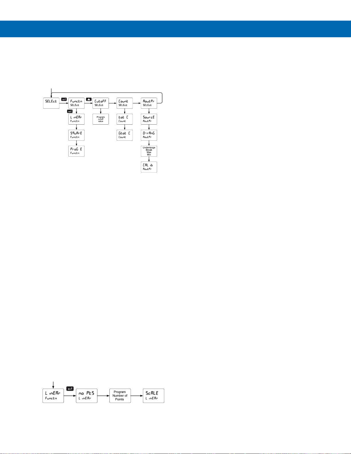
ProtEX-MAX PD8-6210 Explosion-Proof Analog Input Batch Controller
Instruction Manual
62
Select Menu (SElEct)
The Select menu is used to select the input signal
conditioner applied to the input (linear, square root, or
programmable exponent), low-flow cutoff, and analog
output programming. The multi-point linearization is
part of the linear function selection.
Input Signal Conditioning (Functn)
The Function menu is used to select the input signal
conditioner applied to the input: linear, square root, or
programmable exponent. The multi-point linearization
is part of the linear function selection.
Controllers are set up at the factory for linear function
with 2-point linearization. The linear function provides
a display that is linear with respect to the input signal.
Square Root Linearization (Square)
The square root function can be used to linearize the
signal from a differential pressure transmitter and
display flow rate in engineering units.
Programmable Exponent Linearization (Prog E)
The programmable exponent can be used to linearize
the signal from level transmitters in open-channel flow
applications using weirs and flumes.
Multi-Point Linearization (Linear)
Controllers are set up at the factory for linear function
with 2-point linearization. Up to 32 linearization points
can be selected under the linear function. The
multi-point linearization can be used to linearize the
display for non-linear signals such as those from level
transmitters used to measure volume in odd-shaped
tanks or to convert level to flow using weirs and
flumes with complex exponent.
Low-Flow Cutoff (CutofF)
The low-flow cutoff feature allows the controller to be
programmed so that the often-unsteady output from a
differential pressure transmitter, at low flow rates,
always displays zero on the controller. The cutoff can
be disabled to display negative values.
The cutoff value may be programmed from 0.1 to
999999. The controller will display zero below the
cutoff value. Programming the cutoff value to zero
disables the cutoff feature. The cutoff can be disabled
to display negative values.
Total and Grand Total Count Direction (Count)
By default, the batch total and grand total count up
during batch processes. Count parameter allows this
to change. When set to count down, the batch total
will count down from the preset to 0. When set to
count down, the grand total will count down from a
starting value to zero.
Analog Output Programming (AoutPr)
The Analog Output Programming menu is used to
program the behavior of the 4-20 mA output. The
following parameters and functions are programmed
in this menu:
1. Source: Source for generating the 4-20 mA
output (e.g. Rate)
2. Overrange: Analog output value with display in
overrange condition
3. Underrange: Analog output value with display in
underrange condition
4. Break: Analog output value when loop break is
detected
5. Max: Maximum analog output value allowed
regardless of input
6. Min: Minimum analog output value allowed
regardless of input
7. Calibrate: Calibrate the internal 4-20 mA source
reference used to scale the 4-20 mA output
Page 63
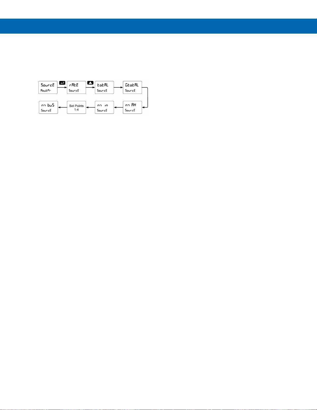
ProtEX-MAX PD8-6210 Explosion-Proof Analog Input Batch Controller
Instruction Manual
63
Analog Output Source
The source for generating the 4-20 mA output may be
assigned to the rate/process variable, total, grand
total, maximum or minimum value reached by the
rate/process, one of the set points, or the Modbus PV
input.
Analog Output Value for Loss of 4-20 mA Input (Loop Break)
The AoutPr - Break menu is used to force the analog
output to go to a user-specified mA value if a break
condition is detected in the 4-20 mA input loop.
Selecting Ignore causes the mA output to go to the
minimum value.
Analog Output Calibration
To perform the analog output calibration, it’s
recommended to use a milliamp meter with a
resolution of at least 0.1 µA to measure the output
current. The values saved internally during this
procedure are used for scaling the 4-20 mA output in
the Setup menu.
Analog Output Calibration Procedure
1. Wire the PD8-6210 4-20 mA output to a current
loop that includes a power supply (internal or
external 12 to 24 VDC), and the mA input on the
digital meter. See Figure 19. 4-20 mA Output
Connections on page 31 for details.
2. Turn on all devices. Allow for a 15 to 30 minute
warm-up.
3. Go to the Advanced Features menu, navigate to
Select (Select) and choose Analog Output
Programming (AoutPr)/Calibration (Calib) menu
and press Enter.
4. The display will show 4 nmA. The PD8-6210 mA
output should now be close to 4 mA. Press Enter
and the display will show 04.000. Enter the actual
value read by the digital mA meter and press
Enter.
5. The display will show 20 nmA. The PD8-6210 mA
output should now be close to 20 mA. Press
Enter and the display will show 20.000. Enter the
actual value read by the digital mA meter and
press Enter.
6. The controller will now calculate the calibration
factors and store them.
7. Press Menu to exit and return to Run mode.
Page 64

ProtEX-MAX PD8-6210 Explosion-Proof Analog Input Batch Controller
Instruction Manual
64
Programmable Function Keys User Menu (user)
• Changing the programming of the F1-F3 function
keys will disable the default batch operation of
these keys, and is not recommended for batch
control applications.
The User menu allows the user to assign the front
panel function keys F1, F2, and F3, the digital input
F4 (located on the input signal connector), and four
digital inputs (located on the digital I/O connector) to
access most of the menus or to activate certain
functions immediately (e.g. reset max & min, hold
relay states, etc.). This allows the controller to be
greatly customized for use in specialized applications.
The four digital outputs can be assigned to a number
of actions and functions executed by the controller
(i.e. alarms, relay acknowledgement, reset max, min,
or max & min.). The digital outputs can be used to
trigger external alarms or lights to indicate these
specific events.
Function Keys & Digital I/O Available Settings
Refer to the following table for descriptions of each
available function key or digital I/O setting.
Display
Description
Start
Starts the batch process
Stop
Stops the batch process
srtstp
Allows the same function key to both
start and stop the batch process
Rly d
Disable all relays until a button
assigned to enable relays (Rly E) is
pressed
Rly E
Enable all relays to function as they
have been programmed
O Hold
Hold current relay states and analog
output as they are until a button
assigned to enable relays (Rly E) is
pressed
d Hold
Hold the current display value, relay
states, and analog output momentarily
while the function key or digital input is
active. The process value will continue
to be calculated in the background.
Ln1 Hi
Display maximum display value on line 1
Ln1 Lo
Display minimum display value on line 1
Ln1 HL
Display maximum & minimum display
values on line 1
Ln2 Hi
Display maximum display value on line 2
Ln2 Lo
Display minimum display value on line 2
Ln2 HL
Display maximum & minimum display
values on line 2
Ln2 gt
Display the grand total on line 2
Ln2 bc
Display the batch count on line 2
Display
Description
Contrl
Directly access the manual control
menu
disabl
Disable the selected function key or
digital I/O
AcH
Acknowledge all active relays that are in
a manual operation mode such as
auto-manual or latching
Reset
Directly access the reset menu
Rst t
Reset the total
Rst gt
Reset the grand total
Rst bc
Reset the batch count
Rst Hi
Reset the maximum display value
Rst Lo
Reset the minimum display value
Rst HL
Reset the maximum & minimum display
values
relay
Directly access the relay menu
preset
Change the preset value
Set 2*
Directly access the set point menu for
relay 2 (*through 4)
nmenu
Mimic the menu button functionality
(digital inputs only)
rigHt
Mimic the right arrow/F1 button
functionality (digital inputs only)
up
Mimic the up arrow/F2 button
functionality (digital inputs only)
Enter
Mimic the enter/F3 button functionality
(digital inputs only)
F On 1*
Force relay 1 (*through 4) into the on
state. This function is used in
conjunction with a digital input to
achieve interlock functionality. See
Setting Up the Interlock Relay (Force
On) Feature on page 50 for details
about interlock relays.
Alnm 1*
Provide indication when alarm 1
(*through 4) has been triggered
(digital outputs only)
Page 65
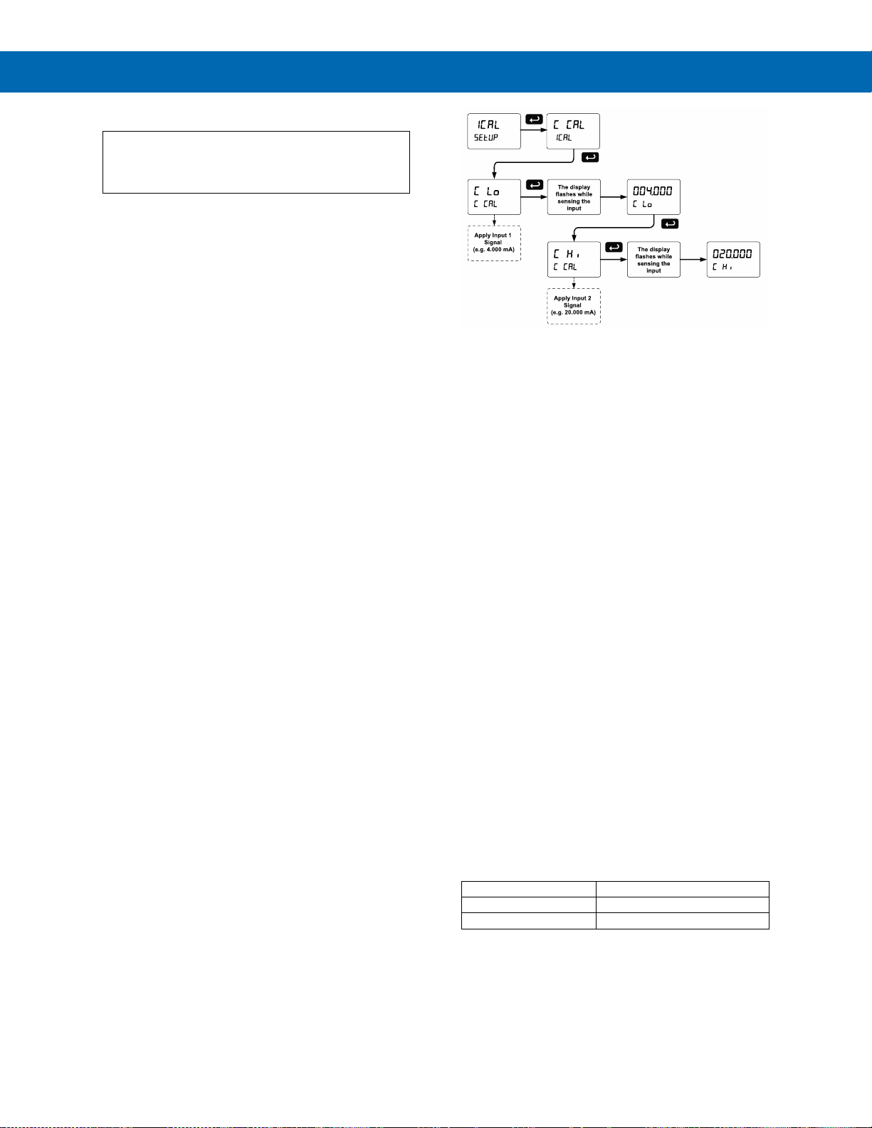
ProtEX-MAX PD8-6210 Explosion-Proof Analog Input Batch Controller
Instruction Manual
65
Internal Source Calibration (ICAL)
The controller is factory calibrated prior to
shipment for milliamps and volts with calibration
equipment that is certified to NIST standards.
The use of a calibrated signal source is necessary to
calibrate the internal source of the controller. The
controller’s internal source is what allows the user to
scale the controller without applying a signal.
Check calibration of the controller at least every
12 months. Each input type must be recalibrated
separately.
Notes:
1. If controller is in operation and it is intended to accept
only one input type (e.g. 4-20 mA), recalibration of
other input is not necessary.
2. Allow the controller to warm up for at least
15 minutes before performing the internal source
calibration procedure.
The Internal calibration menu is part of the Advanced
Features menu.
1. Press and hold the Menu button for three
seconds to access the advanced features of the
controller.
2. Press the Up arrow button to scroll to the Internal
calibration menu (ICAL) and press Enter.
3. The controller displays either current calibration
(C CAL) or voltage calibration (v CAL), according
to the input setup. Press Enter to start the
calibration process.
Example of Internal Calibration for current
input:
4. The controller displays low input current message
(C lo). Apply the low input signal and press
Enter. The display flashes for a moment while the
controller is accepting the low input signal.
5. After the display stops flashing, a number is
displayed with the leftmost digit brighter than the
rest. The bright digit is the active digit that can be
changed by pressing the Up arrow button. Press
the Right arrow button to move to the next digit.
6. Set the display value to correspond to the input
signal being calibrated, typically 4.000 mA.
7. The display moves to the high input calibration
(C Hi). Apply the high input signal and press
Enter.
8. Set the display for the high input calibration, in
the same way as it was set for the low input
calibration, typically 20.000 mA.
The graphic above shows the calibration of the
current input. The voltage input is calibrated in a
similar way.
Tips:
• Low and high input signals can be any valid value
within the range of the controller.
• Observe minimum input span requirements
between input 1 and input 2.
• Low input should be less than high input signal.
Error Message (Error)
An error message indicates that the calibration or
scaling process was not successful.
After the error message is displayed, the controller
reverts to the input prior to the failure during
calibration or scaling and to input 1 during internal
calibration, allowing the appropriate input signal to be
applied or programmed.
The error message might be caused by any of the
following conditions:
1. Input signal is not connected to the proper
terminals, or it is connected backwards*.
2. Wrong signal selection in Setup menu*.
3. Minimum input span requirements not
maintained.
4. Input 1 signal inadvertently applied to calibrate
input 2*.
*Not relevant when scaling the controller.
Minimum Input Span
The minimum input span is the minimum difference
between input 1 and 2 signals required to complete
the calibration or scaling of the controller.
Input range
Input 1 & input 2 span
4-20 mA
0.15 mA
10 VDC
0.10 VDC
Page 66
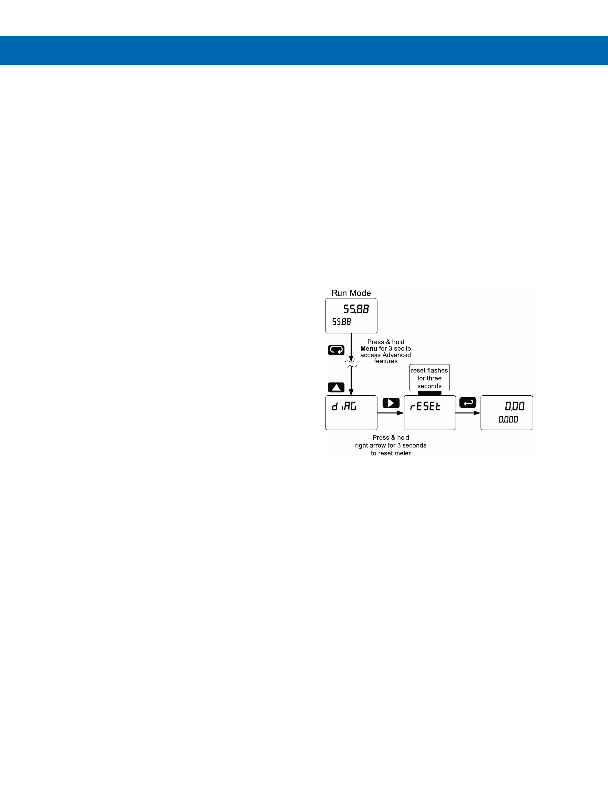
ProtEX-MAX PD8-6210 Explosion-Proof Analog Input Batch Controller
Instruction Manual
66
Troubleshooting
Due to the many features and functions of the
controller, it’s possible that the setup of the controller
does not agree with what an operator expects to see.
If the controller is not working as expected, refer to
the Diagnostics menu and recommendations below.
Diagnostics Menu (diag)
The Diagnostics menu is located in the Advanced
Features Menu; to access the Diagnostics menu refer
to page 59.
This menu allows the user to test the functionality of
all the controller LEDs, check the controller’s software
and version information, and erase the MeterView Pro
software installation files from the controller. Press the
Enter button to view the settings and the Menu button
to exit at any time.
For a description of the diagnostic messages, see
Advanced Features Menu & Display Messages, page
59.
Testing the Display LEDs
To test all LEDs on the display:
1. Go to the Diagnostics menu (diAG) and
press Enter button.
2. Press Up arrow button and scroll to
LED Test menu (led t)
3. Press the Enter button to activate the LED
Test. The controller will cycle through all
digits, decimal points, and relay indicators to
enable the operator to check that all LEDs
are functioning properly.
4. Press the Enter button again to access the
Information menu (Info) or press the Menu
button to return to Run Mode.
Determining Software Version
To determine the software version of a controller:
1. Go to the Diagnostics menu (diAG) and
press Enter button.
2. Press Up arrow button and scroll to
Information menu (Info).
3. Press Enter to access the software
number (SFT) and version (UER)
information. Write down the information as
it is displayed. Continue pressing Enter
until all the information is displayed.
4. The controller returns to Run Mode after
displaying all the settings.
Reset Controller to Factory Defaults
When the parameters have been changed in a way
that is difficult to determine what’s happening, it might
be better to start the setup process from the factory
defaults.
Instructions to load factory defaults:
1. Enter the Advanced Features menu. See
Advanced Setup & Programming, page 59.
2. Press Up arrow to go to Diagnostics (diag) menu
3. Press and hold Right arrow for three seconds,
press Enter when display flashes reset.
Note: If Enter is not pressed within three seconds, the
display returns to the Diagnostics menu.
4. The controller goes through an initialization
sequence (similar as on power-up) and loads the
factory default settings.
Page 67

ProtEX-MAX PD8-6210 Explosion-Proof Analog Input Batch Controller
Instruction Manual
67
Factory Defaults & User Settings
The following table shows the factory setting for the
major programmable parameters on the controller.
Factory Defaults & User Settings
Parameter
Display
Default Setting
Input type
Input
4-20 mA
Total
yes
Total enabled
Units
units
Rate / total / G total
mA / mA / mA
Rate decimal
point
ddd.ddd
3 Places
Total decimal
point
ddddd.d
1 Place
Grand Total
decimal point
dddddd
0 Places
Function
Functn
Linear
Number of points
No Pts
2
Programming
prog
Scale
Input 1
InP 1
4.000 mA
Display 1
Dis 1
4.000
Input 2
InP 2
20.000 mA
Display 2
Dis 2
20.000
Display line 1
Line 1
Display batch total
Display line 2
Line 2
Display preset
Display intensity
d-Inty
6
Total time base
T tb
Second
Total conversion
factor
T CF
1.000
Batch mode
nmode
Manual
Grand total time
base
GT tb
Second
Grand total
conversion factor
T CF
1.000
Grand total reset
T rst
Manual
Relay 1
assignment
Asign1
Total
Relay 2
assignment
Asign2
Total
Relay 2 preclose
preCls
No
Relay 3
assignment
Asign3
Rate
Relay 4
assignment
Asign4
Rate
Relay 1 action
Act 1
Automatic
Batch preset
Preset
100.0
Relay 2 action
Act 2
Automatic
Relay 2 set point
Set 2
200.0
Relay 3 action
Act 3
Automatic
Relay 3 set point
Set 3
3.000
Relay 3 reset
point
RSt 3
2.500
Relay 4 action
Act 4
Automatic
Factory Defaults & User Settings
Parameter
Display
Default Setting
Relay 4 set point
Set 4
4.000
Relay 4 reset
point
RSt 4
3.500
Fail-safe relay 1
Fls 1
Off
Fail-safe relay 2
Fls 2
Off
Fail-safe relay 3
Fls 3
Off
Fail-safe relay 4
Fls 4
Off
On delay relay 1
On 1
0.0 sec
Off delay relay 1
Off 1
0.0 sec
On delay relay 2
On 2
0.0 sec
Off delay relay 2
Off 2
0.0 sec
On delay relay 3
On 3
0.0 sec
Off delay relay 3
Off 3
0.0 sec
On delay relay 4
On 4
0.0 sec
Off delay relay 4
Off 4
0.0 sec
Loop break
relay 1
ignore
Ignore
Loop break
relay 2
ignore
Ignore
Loop break
relay 3
ignore
Ignore
Loop break
relay 4
ignore
Ignore
Display 1
analog out
Dis 1
4.000
Output 1 value
Out 1
4.000 mA
Display 2
analog out
Dis 2
20.000
Output 2 value
Out 2
20.000 mA
Source analog
output
Source
Rate/process
Overrange
output
O-rang
21.000 mA
Underrange
output
u-rang
3.000 mA
Loop break
output
break
1.000 mA
Filter
filter
70
Bypass
Bypass
0.2
Cutoff value
CutofF
0.0 (disabled)
Maximum output
nmAx
23.000 mA
Minimum output
nmin
1.000 mA
Slave ID
(Address)
SlaVId
247
Baud rate
baud
9600
Transmit delay
Tr dly
50 ms
Parity
Parity
Even
Byte-to-byte
timeout
t-byt
010 (0.1 sec)
F1 function key
F1
Start
F2 function key
F2
Preset
Page 68

ProtEX-MAX PD8-6210 Explosion-Proof Analog Input Batch Controller
Instruction Manual
68
Factory Defaults & User Settings
Parameter
Display
Default Setting
F3 function key
F3
Stop
F4 function
F4
Start/Stop
Digital input 1
dI 1
Menu
Digital input 2
dI 2
Right arrow
Digital input 3
dI 3
Up arrow
Digital input 4
dI 4
Enter
Digital output 1-4
dO 1
Alarm 1-4
Password 1
Pass 1
000000 (unlocked)
Password 2
Pass 2
000000 (unlocked)
Password 3
Pass 3
000000 (unlocked)
Total password
Total
000000 (unlocked)
Grand total
password
Gtotal
000000 (unlocked)
Page 69

ProtEX-MAX PD8-6210 Explosion-Proof Analog Input Batch Controller
Instruction Manual
69
Troubleshooting Tips
This controller is a highly sophisticated instrument with an extensive list of features and capabilities. If the
programming buttons are used to program the controller, it may be a difficult task to keep everything straight. That is
why we strongly recommend the use of the free MeterView Pro software for all programming activities. A USB cable
is provided with the controller for programming with MeterView Pro software.
If you have programmed the controller with the programming buttons and it is not working as intended, try reprogramming the controller using MeterView Pro software.
Symptom
Check/Action
No display at all
Check power at power connector
Not able to change setup or programming,
Locd is displayed
Controller is password-protected; enter correct six-digit password to
unlock or Master Password of 508655
Controller does not respond to input change
If a Low-Flow Cutoff Value has been programmed, the controller will
display zero below that point, regardless of the input – which can
appear like the controller is not responding to an input change. Check
to make sure the problem is not being caused by an undesired
low-flow cutoff value.
To prevent the display from showing a negative value, set the
low-flow cutoff to a value greater than zero.
Controller displays error message during
calibration (Error)
Check:
1. Signal connections
2. Input selected in Setup menu
3. Minimum input span requirements
Controller displays
1. 999999
2. -99999
Check:
1. Input selected in Setup menu
2. Corresponding signal at Signal connector
Display is unstable
Check:
1. Input signal stability and value
2. Display scaling vs. input signal
3. Filter and bypass values (increase)
Display response is too slow
Check filter and bypass values
Display reading is not accurate
Check:
1. Input signal conditioner selected: Linear, square root, etc.
2. Scaling or calibration
Display does not respond to input changes,
reading a fixed number
Check display assignment, it might be displaying max, min, or set
point
Display alternates between
1. Hi and a number
2. Lo and a number
Press Menu to exit max/min display readings
Relay operation is reversed
Check:
1. Fail-safe in Setup menu
2. Wiring of relay contacts
Relay and status LED do not respond to signal
Check:
1. Relay action in Setup menu
2. Set and reset points
Flashing relay status LEDs
Relays in manual control mode or relay interlock switches opened
Controller not communicating with application
programs
Check:
1. M-Link Connector installed between PROVU electronics and
ProtEX-MAX connector board. See Figure 4: Integrated
PROVU Required Connections on page 26
3. Serial settings
4. Controller address and baud rate
If the display locks up or the controller does not
respond at all
Cycle the power to reboot the microprocessor
Page 70
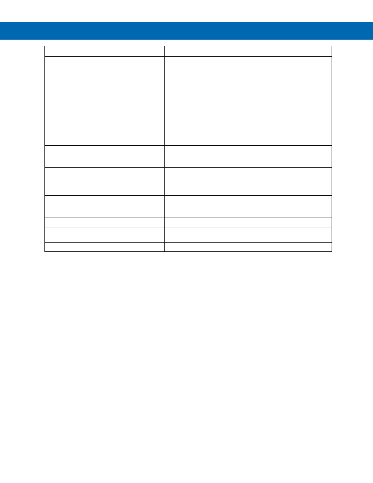
ProtEX-MAX PD8-6210 Explosion-Proof Analog Input Batch Controller
Instruction Manual
70
Symptom
Check/Action
Cannot access main menu
You cannot access the main menu when a batch is running. Make
sure the batch has stopped before trying to access the main menu.
Batch is continuously overfilling
A multi-stage batch with a pre-close amount may be necessary. See
Two-Stage Batch Control Setup Using Relays 1 & 2 on page 54.
Batch is not stopping when preset is reached
Check wiring. Relay 1 corresponds to the preset value.
SafeTouch buttons do not respond
1. If mechanical button was pushed, the SafeTouch buttons will
be re-enabled automatically 60 seconds after the last button
push.
2. If slide switch on connector board is in DISABLE position,
switch to ENABLE.
3. Strong direct sunlight may interfere with SafeTouch button
operation. It is recommended to operate the buttons by
standing so as to block direct sunlight.
Serial Communications METER LED Indicator is
off
Check:
1. Modular cable connection
2. Power to the device
If only the TX (or DATA IN) data status LED is
flashing when serial communications attempted
Check:
1. Serial cable
2. Instrument address & baud rate
3. Program address & baud rate
If both data status LEDs (TX and RX) are off
when trying to communicate
Remove all unnecessary cables and instruments from the bus.
Try getting the system to work with only one device (to ease
troubleshooting) and then expand the system one device at a time.
Communications slow
Increase the baud rate
Random communication errors
1. Increase the TX delay time
2. Decrease the baud rate
Other symptoms not described above
Call Technical Support for assistance
Note: Certain sequences of events can cause unexpected results. To solve these issues, it is best to start fresh from factory
defaults and use the manual as a step by step programming guide, rather than a random approach to programming. To reset the
controller to factory defaults, see Reset Controller to Factory Defaults on page 66. In addition, for best results, we recommend using
the free MeterView Pro software for all programming needs.
Page 71
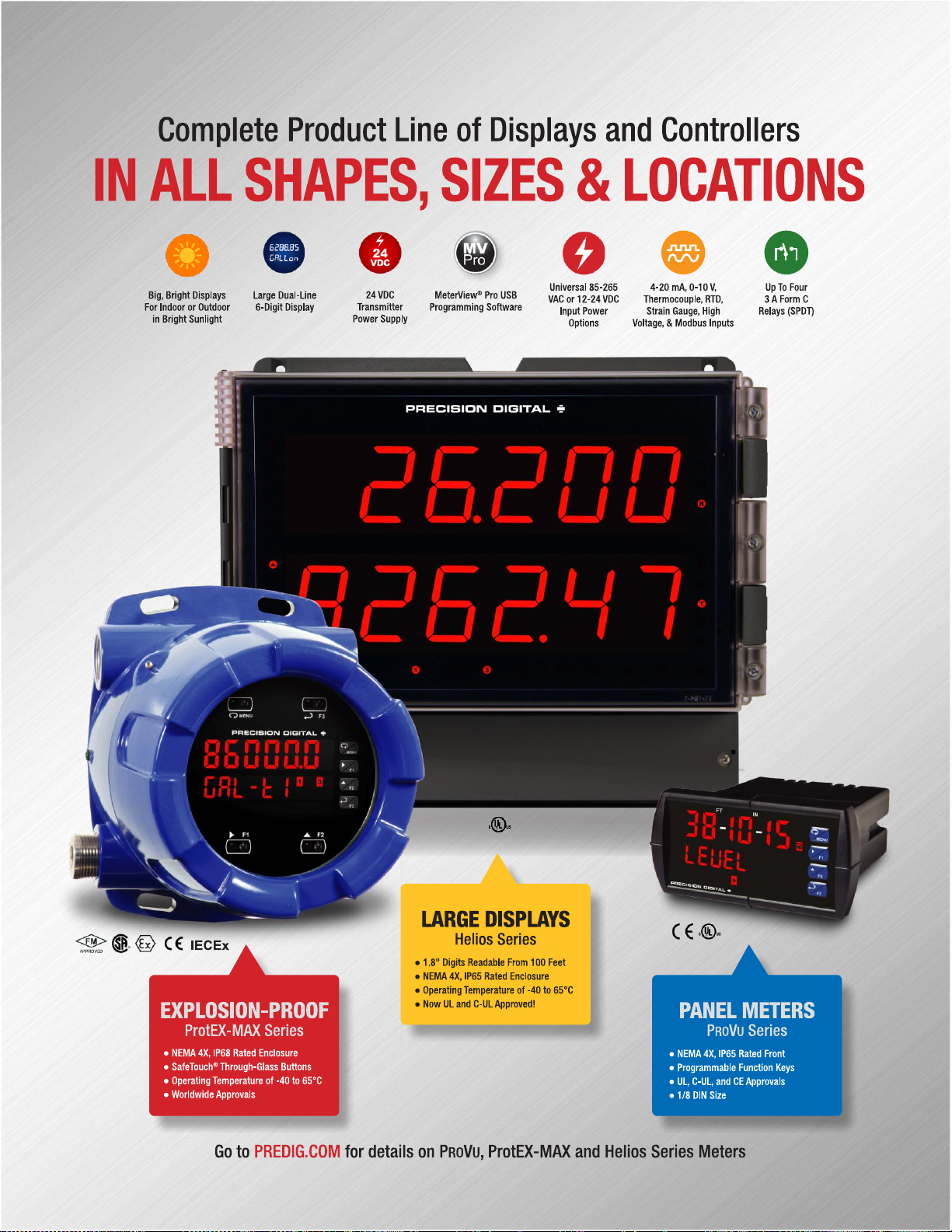
71
Page 72

ProtEX-MAX PD8-6210 Explosion-Proof Analog Input Batch Controller
Instruction Manual
PRECISION DIGITAL CORPORATION
233 South Street • Hopkinton MA 01748 USA
Tel (800) 343-1001 • Fax (508) 655-8990
www.predig.com
LIM8-6210_F
SFT039 Ver 4.010 & up
07/22
Contact Precision Digital
Technical Support
Call: (800) 610-5239 or (508) 655-7300
Fax: (508) 655-8990
Email: [email protected]
Sales Support
Call: (800) 343-1001 or (508) 655-7300
Fax: (508) 655-8990
Email: [email protected]
Place Orders
Email: [email protected]
For the latest version of this manual please visit
www.predig.com
 Loading...