

Page 1
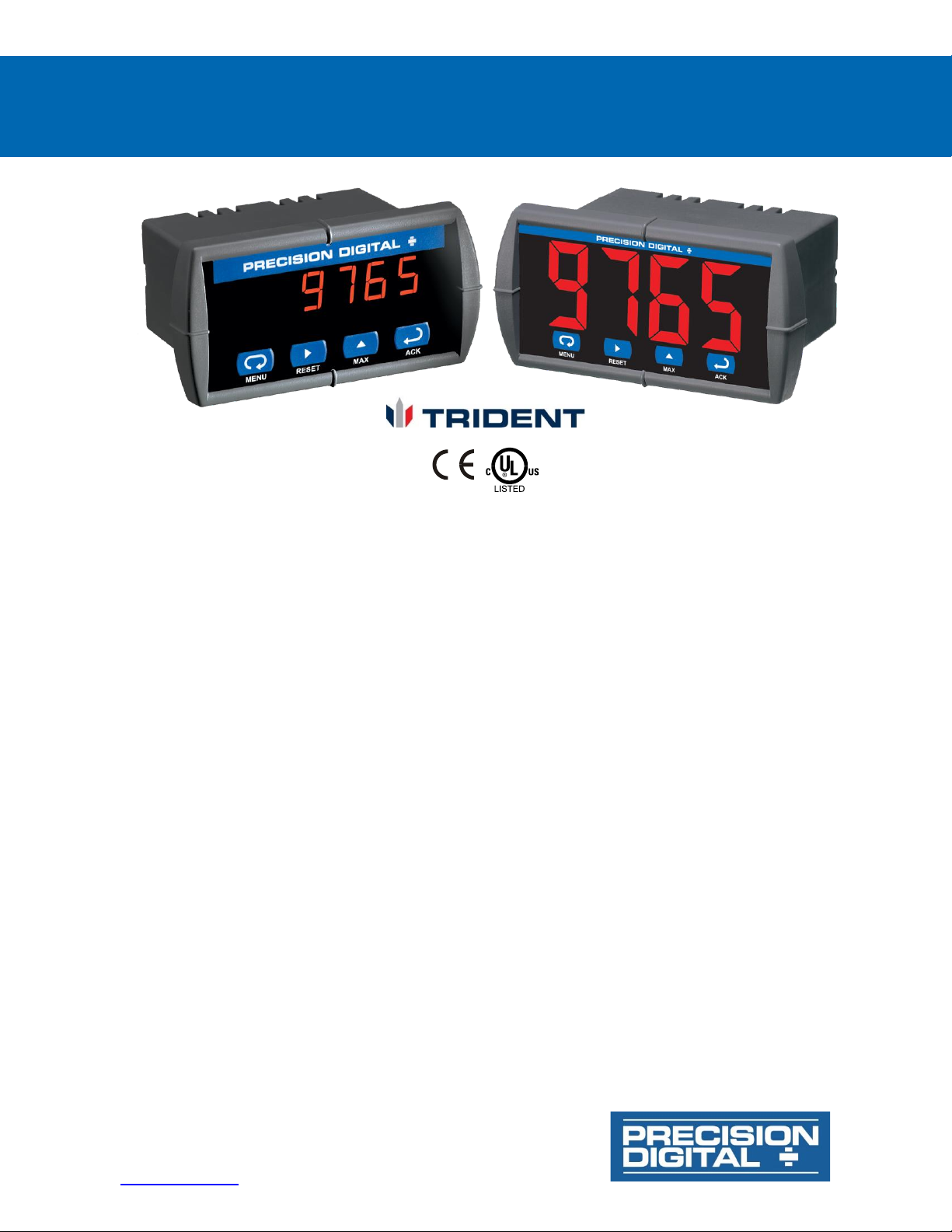
Trident Series PD765 Process & Temperature Meters
Instruction Manual
PRECISION DIGITAL CORPORATION
233 South Street • Hopkinton MA 01748 USA
Tel (800) 343-1001 • Fax (508) 655-8990
www.predig.com
• 1/8 DIN Digital Panel Meter with NEMA 4X, IP65 Front
• 4-20 mA, ± 10 V, TC & RTD Field Selectable Inputs
• Easy Field Scaling in Engineering Units without Applying an Input
• Full 4-Digit Display, 0.56" (14.2 mm) or 1.20" (30.5 mm)
• Shallow Depth Case Extends Only 3.6" (91 mm) Behind Panel
• Isolated 24 VDC @ 200 mA Transmitter Power Supply Option
• 2 Relays + Isolated 4-20 mA Output Options
• Free PC-Based MeterView Programming & Monitoring Software
• No Assembly Required
• Sunlight Readable Display
• Operating Temperature Range: -40 to 65°C (-40 to 149°F)
• UL & C-UL Listed. E160849; UL 508 Industrial Control Equipment
• Input Power Options: 85-265 VAC / 90-265 VDC or 12-36 VDC / 12-24 VAC
• Duplex Pump Controller with Alternation Capability
• External Contacts for Remote Button Operation (Trident X2 Only)
• USB, RS-232, & RS-485 Serial Communication Adapters Options
• Modbus RTU Communication Protocol Standard
• Copy Meter Settings to Other Trident Meters
• Password Protection
• Max/Min Display
• High & Low Alarms with Multiple Reset Actions
• Wide Assortment of NEMA 4X Enclosures for up to Ten Meters
• Light / Horn & Reset Button Accessory for Trident X2
• Control Station Accessory for Remote Operation of Trident X2
• 3-Year Warranty
Page 2
Trident Series PD765 Process & Temperature Meters
Instruction Manual
2
Disclaimer
The information contained in this document is
subject to change without notice. Precision Digital
makes no representations or warranties with
respect to the contents hereof and specifically
disclaims any implied warranties of
merchantability or fitness for a particular purpose.
See Warranty Information and Terms &
Conditions on www.predig.com for complete
details.
• Read complete instructions prior to installation
and operation of the meter.
• Risk of electric shock or personal injury.
• This product is not recommended for life support
applications or applications where malfunctioning
could result in personal injury or property loss.
Anyone using this product for such applications
does so at his/her own risk. Precision Digital
Corporation shall not be held liable for damages
resulting from such improper use.
WARNING
Cancer and Reproductive Harm - www.P65Warnings.ca.gov
Limited Warranty
Precision Digital Corporation warrants this
product against defects in material or
workmanship for the specified period under
“Specifications” from the date of shipment from
the factory. Precision Digital’s liability under this
limited warranty shall not exceed the purchase
value, repair, or replacement of the defective unit.
See Warranty Information and Terms &
Conditions on www.predig.com for complete
details.
Registered Trademarks
All trademarks mentioned in this document are
the property of their respective owners.
© 2022 Precision Digital Corporation.
All rights reserved.
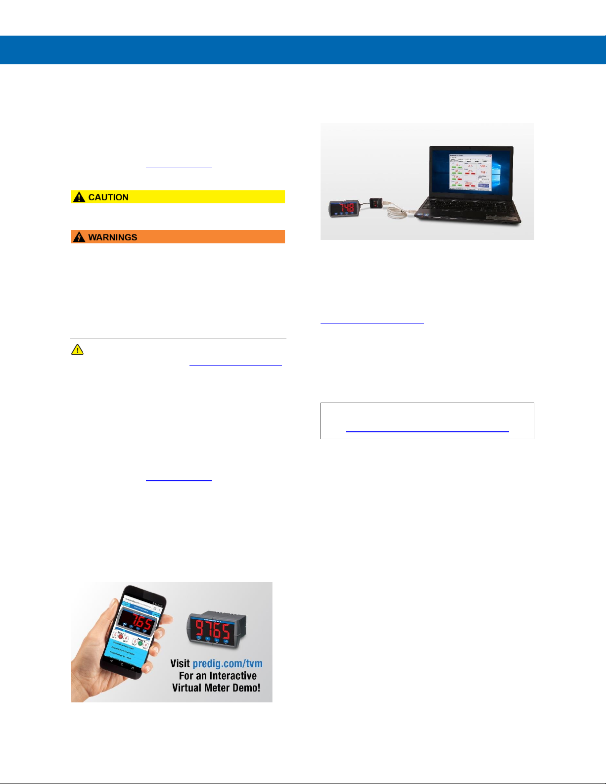
FREE MeterView
Programming Software
Note: Trident meter is not powered from USB connection
and requires external power to be programmed.
The easiest and quickest way to program your Trident
meter is to use the FREE MeterView software. We will
even send you a PDA8006 USB adapter, normally sold
for $39.00, at no cost if you register your meter at
www.predig.com/free8006 (limit one per customer).
You can program the Trident meter you just bought
with the front panel buttons and have the PDA8006
on hand for programming future meters.
MeterView software is intuitive, and most customers
can get their meter programmed as they like without
even looking in the manual.
Watch MeterView Software Video at
https://www.predig.com/meterview
In addition to programming, the software, with
additional devices, may be used for:
• Monitoring up to 100 Trident meters
• Datalogging using your PC
• Generating and saving programming files for
later use
Once your meter is programmed the way you want it,
you can wire it up for your application per the
instructions in this manual and install it. If you find that
you need to make adjustments to the programming
after the meter is installed, you can use the front panel
buttons and the instructions in this manual to do so.
Page 3

Trident Series PD765 Process & Temperature Meters
Instruction Manual
3
Table of Contents
Introduction ......................................................................................................... 6
Ordering Information .......................................................................................... 6
Specifications ..................................................................................................... 8
General ............................................................................................................ 8
Process Input .................................................................................................. 8
Temperature Inputs ........................................................................................ 8
Relays Option .................................................................................................. 9
Serial Communications .................................................................................. 9
Isolated 4-20 mA Transmitter Output ............................................................ 9
External Button Contacts (X2 Models Only) ................................................. 9
MOD-LH Light / Horn .................................................................................... 10
Compliance Information................................................................................... 10
Safety ............................................................................................................. 10
Electromagnetic Compatibility .................................................................... 10
EU Declaration of Conformity .......................................................................... 11
Safety Information ............................................................................................ 11
Installation......................................................................................................... 12
Unpacking ..................................................................................................... 12
Panel Mounting ............................................................................................. 12
Mounting Dimensions .................................................................................. 12
Connections .................................................................................................. 13
Connector Labeling ..................................................................................... 13
Power Connections ..................................................................................... 15
Signal Connections ..................................................................................... 15
Serial Communication ................................................................................. 16
Relays and 24 V Output Connections ......................................................... 17
Switching Inductive Loads ........................................................................... 17
4-20 mA Output & Input Signal Connections ............................................... 18
Isolated 4-20 mA Signal Splitters & Converters ......................................... 19
Isolated 4-20 mA Signal Splitter .................................................................. 19
4-20 mA to 0-10 VDC Signal Converter....................................................... 19
External Button Contacts on Trident X2 ..................................................... 19
Four-Position Control Station for Remote Operation of Trident
PD765 X2 Buttons ......................................................................................... 19
Setup and Programming .................................................................................. 20
Overview ........................................................................................................ 20
Front Panel Buttons and Status LED Indicators ........................................ 20
Display Functions and Messages ................................................................... 21
Main Menu ..................................................................................................... 22
Setting Numeric Values ................................................................................ 22
Setting Up the Meter (setu) .......................................................................... 22
Setting the Input Signal (inpt) .................................................................... 22
Setting the Decimal Point (dc.pt) ................................................................. 23
Setting the Temperature Scale (F C) ......................................................... 23
Programming the Meter (prog) .................................................................... 23
Scaling the Meter (scal) ............................................................................. 23
Calibrating the Meter (Cal) .......................................................................... 24
Recalibrating Temperature Inputs (Cal) ...................................................... 24
Recalibrating Process Inputs (ICal)............................................................ 24
Setting the Relay Operation (rely) ............................................................. 25
Relay and Alarm Operation ......................................................................... 26
Scaling the 4-20 mA Analog Output (Aout) ................................................. 30
Isolated 4-20 mA Signal Splitters & Converters ........................................... 30
Program the Sensor Break Output Value (SEbr) ......................................... 30
Analog Output when Display is Out of Range ............................................. 30
Page 4

Trident Series PD765 Process & Temperature Meters
Instruction Manual
4
Setting Up the Password (pass) .................................................................. 31
Locking the Meter ........................................................................................ 31
Unlocking the Meter .................................................................................... 31
Advanced Features Menu ............................................................................ 31
Advanced Features Menu & Display Messages .......................................... 31
Offset Adjustment (Adj) ............................................................................... 32
Noise Filter (fltr) ....................................................................................... 32
Noise Filter Bypass (byps) .......................................................................... 32
Serial Communications (serl) .................................................................... 33
Protocol Selection Menu (Prot) .................................................................. 33
Select Menu (SElc) ................................................................ ..................... 33
Linear or Square Root Function (linr or Sqrt) .......................................... 33
Low-Flow Cutoff (cutF) ................................ ................................ ............... 33
Display Intensity (inty) ............................................................................... 34
Meter Copy Function (Copy) ........................................................................ 34
Meterview Software .......................................................................................... 35
Remote Programming .................................................................................. 35
Data Acquisition ........................................................................................... 35
Monitoring ................................ ..................................................................... 35
Monitoring System Parts .............................................................................. 35
MeterView Installation .................................................................................. 35
Running MeterView the First Time .................................................................. 35
Enable Meter and Select Meter Address ..................................................... 35
MeterView Main Window .............................................................................. 36
Main Window Menus ................................................................................... 36
Configuration Window .................................................................................. 37
File Menu ..................................................................................................... 37
Tools Menu .................................................................................................. 37
Password Menu ........................................................................................... 38
Input Tab ..................................................................................................... 38
Set Up Input Type ....................................................................................... 38
Set Up Decimal Point .................................................................................. 38
Set Up Temperature Unit............................................................................. 38
Set Up Temperature Sensor ........................................................................ 38
Scaling Tab ................................................................................................. 39
Relays/Alarms Tab ...................................................................................... 39
Advanced Tab ............................................................................................. 39
Info Tab ....................................................................................................... 39
Customize Window ....................................................................................... 39
Serial Communication Setup ....................................................................... 40
Relays/Alarms Status ................................................................................... 40
Logging Meter Data to File ........................................................................... 40
Log File Sample .......................................................................................... 40
Internal Calibration (ICal) ........................................................................... 41
Operation........................................................................................................... 42
Front Panel Buttons Operation .................................................................... 42
Maximum/Minimum Readings ..................................................................... 42
Remote Operation of Trident X2 Front Panel Buttons ............................... 42
Troubleshooting ............................................................................................... 43
Diagnostics Menu (diag) .............................................................................. 43
Determining Software Version ..................................................................... 43
Reset Meter to Factory Defaults .................................................................. 43
Factory Defaults & User Settings ................................................................ 44
Troubleshooting Tips ................................................................................... 45
Quick Interface Reference Guide ................................................................ .... 46
Page 5

Trident Series PD765 Process & Temperature Meters
Instruction Manual
5
Table of Figures
Figure 1. Panel Cutout and Mounting ................................................................. 12
Figure 2. Meter Dimensions – Side View ............................................................ 12
Figure 3. Case Dimensions – Top View .............................................................. 12
Figure 4. Connector Labeling for PD765-#R0-00 ............................................... 13
Figure 5. Connector Labeling for PD765-6R0-10 ............................................... 13
Figure 6. Connector Labeling for PD765-#R2-00 ............................................... 13
Figure 7. Connector Labeling for PD765-6R2-10 ............................................... 13
Figure 8. Connector Labeling for PD765-#R3-00 ............................................... 13
Figure 9. Connector Labeling for PD765-6R3-10 ............................................... 13
Figure 10. Connector Labeling for PD765-6R3-20 ............................................. 13
Figure 11. Connector Labeling for PD765-7R5-00 ............................................. 14
Figure 12. Connector Labeling for PD765-6R5-10 ............................................. 14
Figure 13. Connector Labeling for PD765-#X0-00 .............................................. 14
Figure 14. Connector Labeling for PD765-6X0-10 .............................................. 14
Figure 15. Connector Labeling for PD765-#X2-00 .............................................. 14
Figure 16. Connector Labeling for PD765-6X2-10 .............................................. 14
Figure 17. Connector Labeling for PD765-#X3-00 .............................................. 14
Figure 18. Connector Labeling for PD765-6X3-10 .............................................. 14
Figure 19. Connector Labeling for PD765-6X3-20 .............................................. 15
Figure 20. Connector Labeling for PD765-7X5-00 .............................................. 15
Figure 21. Connector Labeling for PD765-6X5-10 .............................................. 15
Figure 22. Power Connections ............................................................................ 15
Figure 23. Transmitter Powered by Internal Supply (Optional) ........................ 15
Figure 24. Transmitter Powered by External Supply or Self-Powered ............. 15
Figure 25. Voltage Input Connections ................................................................ 15
Figure 26. Thermocouple Input Connections ..................................................... 16
Figure 27. Three-Wire RTD Input Connections .................................................. 16
Figure 28. Two-Wire RTD Input Connections ..................................................... 16
Figure 29. Four-Wire RTD Input Connections .................................................... 16
Figure 30. Relay & 24 V Output Connections ..................................................... 17
Figure 31. AC and DC Loads Protection ............................................................. 17
Figure 32. Low Voltage DC Loads Protection .................................................... 17
Figure 33. 4-20 mA Output & Input Signal Powered by Meter .......................... 18
Figure 34. 4-20 mA Output Powered by Meter ................................................... 18
Figure 35. 4-20 mA Output Powered Externally ................................................. 18
Figure 36. Trident X2 Powers Both the Heater and 4-20 mA Input Signal ....... 18
Figure 37. Passive 4-20 mA Output from Trident Meter Split into Two
Isolated 4-20 mA Signals ..................................................................................... 19
Figure 38. Passive 4-20 mA Output from Trident Meter Converted to 0-10
VDC Signal .......................................................................................... 19
Figure 39. Meter Copy Connection ..................................................................... 34
Page 6
Trident Series PD765 Process & Temperature Meters
Instruction Manual
6
Introduction
The PD765 Trident digital panel meter is one of the
most versatile digital panel meters on the market and
will satisfy a wide variety of process and temperature
applications. The Trident can be field programmed to
accept process voltage (0-5V, 1-5V, etc) and current
(4-20 mA) inputs, 100 Ohm RTDs, and the four most
common thermocouple types.
One of the Trident’s most useful features is its ability
to provide 24 VDC to power the transmitter’s 4-20 mA
signal. This reduces costs and simplifies wiring. The
Trident is housed in a shallow-depth, 1/8 DIN enclosure
that features a NEMA 4X front panel and convenient
mounting hardware. There are two power options for
the Trident: 85 to 265 VAC or 12-36 VDC and certain
configurations of the AC powered meter can provide
24 VDC to power the transmitter, if needed.
Programming and setup can be performed with the four
front panel pushbuttons, free MeterView software, or
using the Copy function.
Two relays and isolated 4-20 mA output options
increase the utility of the Trident meter. The relays can
be used for alarm or control applications. The 4-20 mA
output provides an isolated retransmission of the input
signal; especially useful for temperature inputs like
thermocouples and RTDs.
The display height on the standard Trident meter is
0.56" (14.2 mm) and on the Trident X2 the display
height is an astounding 1.2" (30.5 mm). The Trident X2
can be read easily from distances of up to 30 feet!
The intensity of the display on both versions of the
Trident can be adjusted to compensate for various
lighting conditions, especially direct sunlight.
Ordering Information
Trident
85-265 VAC
Model
12-36 VDC
Model
Options Installed
PD765-6R0-00
PD765-7R0-00
No options
PD765-6R0-10
24 V supply
PD765-6R2-00
PD765-7R2-00
2 relays
PD765-6R2-10
2 relays
24 V supply
PD765-6R3-00
PD765-7R3-00
4-20 mA output
PD765-6R3-10
4-20 mA output
24 V supply
PD765-6R3-20
4-20 mA output
dual 24 V supplies
PD765-7R5-00
2 relays
4-20 mA output
PD765-6R5-10
2 relays
4-20 mA output
24 V supply
Trident X2
85-265 VAC
Model
12-36 VDC
Model
Options Installed
PD765-6X0-00
PD765-7X0-00
No options
PD765-6X0-10
24 V supply
PD765-6X2-00
PD765-7X2-00
2 relays
PD765-6X2-10
2 relays
24 V supply
PD765-6X3-00
PD765-7X3-00
4-20 mA output
PD765-6X3-10
4-20 mA output
24 V supply
PD765-6X3-20
4-20 mA output
dual 24 V supplies
PD765-7X5-00
2 relays
4-20 mA output
PD765-6X5-10
2 relays
4-20 mA output
24 V supply
Accessories
Model
Description
PDA1024-01
24 VDC Power Supply for DIN Rail
PDA7420
Trident Meter Copy Cable, 7' (2.1 m)
PDA7422
Trident RS-485 Serial Adapter
PDA7232
Trident RS-232 Serial Adapter
PDA7485-I
RS-232 to RS-485 Isolated Converter
PDA8006
USB Serial Adapter for Programming
Meter with MeterView Software*
PDA8232-N
USB to RS-232 Non-Isolated Converter
PDA8485-I
USB to RS-485 Isolated Converter
MOD-LH
Light / Horn / Enclosure Modification
PD659
Signal Isolators, Splitters, & Conditioners
PDA2360
Plastic Control Stations
PD9501
Multi-Function Calibrator
PD9502
Low-Cost Signal Generator
PDX6901
Snubber: 0.01 μF/470 Ω, 250 VAC
*See Free 8006 to receive PDA8006 at no charge.
Page 7
Trident Series PD765 Process & Temperature Meters
Instruction Manual
7
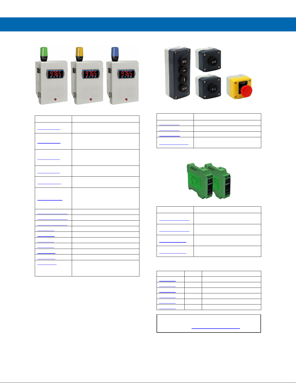
Light / Horn Accessories for Trident X2
Model
Description
MOD-LHRB1
Red Light / Horn and Reset Button
with Holes Drilled in Enclosure
(1)
MOD-LHGB1
Green Light / Horn and Reset
Button with Holes Drilled in
Enclosure
(1)
MOD-LHYB1
Yellow Light / Horn and Reset
Button with Holes Drilled in
Enclosure
(1)
MOD-LHBB1
Blue Light / Horn and Reset Button
with Holes Drilled in Enclosure
(1)
MOD-LHWB1
White Light / Horn and Reset Button
with Holes Drilled in Enclosure
(1)
MOD-LH5CB1
Light / Horn with User Choice of
Red, Green, Yellow, Blue or White
Light, Reset Button, and Holes
Drilled in Enclosure
(1)
PDA-BUTTON1R
Red Reset Button
PDA-BUTTON1G
Green Reset Button
PDA-BUTTON1B
Blue Reset Button
PDA-LHR
Red Light / Horn
PDA-LHG
Green Light / Horn
PDA-LHY
Yellow Light / Horn
PDA-LHB
Blue Light / Horn
PDA-LHW
White Light / Horn
PDA-LHW
White Light / Horn
PDA-LH5C
Light / Horn with User Choice of
Red, Green, Yellow, Blue or White
Light
Note:
1. This MOD supplies the Light / Horn and Reset Button. The
enclosure comes pre-drilled with holes for Light / Horn and Reset
Button and the user performs the installation and wiring. Meter and
enclosure are sold separately. The Light / Horn hole is in the back
left corner of the enclosure and the Reset Button is centered on the
cover of the enclosure below the meter about an inch off the
bottom of the cover except on the PDA3400 series where it is
mounted on the side of the enclosure.
PDA2360 Control Stations for Trident X2
Model
Description
PDA2360-E
Emergency Stop Button
PDA2361-A
1 Black Ack Button
PDA2361-Q
1 Black Silence Button
PDA2364-MRUE
4 Black Buttons: Menu, Right, Up,
Enter
Signal Splitter & Conditioner Accessories
Model
Description
PD659-1MA-1MA
Signal Isolator with One 4-20 mA
Input and One 4-20 mA Output
PD659-1MA-2MA
Signal Splitter with One 4-20 mA
Input and Two 4-20 mA Outputs
PD659-1V-1MA
Signal Conditioner with One 0-10
VDC Input and One 4-20 mA Output
PD659-1MA-1V
Signal Conditioner with One 4-20
mA Input and One 0-10 VDC Output
Enclosures
Series
Meters
Material
PDA2300
1-10
Plastic NEMA 4X
PDA2500
1-6
Plastic NEMA 4X
PDA2600
1-6
Stainless Steel NEMA 4X
PDA2700
1-6
Painted Steel NEMA 4
PDA2800
1-2
Plastic NEMA 4X
PDA3400
1-3
Plastic NEMA 4X
Need help selecting the right enclosure?
Go to www.predig.com/esu
Page 8
Trident Series PD765 Process & Temperature Meters
Instruction Manual
8
Specifications
Except where noted all specifications apply to
operation at +25°C.
General
Display
Trident: 0.56" (14.2 mm);
Trident X2: 1.20" (30.5 mm) red LED,
4 digits (-1999 to 9999)
Display
Intensity
Eight user selectable levels. Default
intensity is 6.
Front Panel
NEMA 4X, IP65; panel gasket provided
Programming
Methods
Four front panel buttons, cloning with
Copy feature, PC with MeterView
software, and Modbus registers.
Noise Filter
Programmable from 2 to 199
(0 will disable filter)
Display
Update Rate
Process/RTD: 3.7-5/second
Thermocouple: 1.8-2.5/second
Overrange
Display flashes 9999
Underrange
Display flashes -1999
Recalibration
All ranges are calibrated at the factory.
Recalibration is recommended at least
every 12 months.
Max/Min
Display
Stored until reset by user or meter is
turned off.
Password
Restricts modification of programmed
settings.
Non-Volatile
Memory
Settings stored for a minimum of 10
years.
Power
Options
85-265 VAC, 50/60 Hz; 90-265 VDC,
20 W max or
12-36 VDC; 12-24 VAC, 6 W max.
Required Fuse
UL Recognized, 5 A max, slow-blow;
up to 6 meters may share one fuse.
Normal Mode
Rejection
64 dB at 50/60 Hz
Isolation
4 kV input/output-to-power line; 500 V
input-to-output or output-to-24 VDC
supplies. -6R5 & -6X5 models only:
100 V output-to-24 VDC supply
Operating
Temperature
-40 to 65°C (-40 to 149°F)
Storage
Temperature
-40 to 85°C (-40 to 185°F)
Relative Humidity
0 to 90% non-condensing
Connections
Power & Signal: removable screw
terminal blocks accept 12 to 22 AWG.
Serial: RJ11 header, standard on all
meters.
Enclosure
1/8 DIN, high impact plastic, UL 94V-0,
color: gray
Tightening
Torque
Screw terminal connectors:
5 lb-in (0.56 Nm)
Weight
9.5 oz. (269 g) (including options)
UL File Number
E160849; UL 508 Industrial Control
Equipment
Warranty
3 years parts & labor. See Warranty Information and Terms & Conditions on
www.predig.com for complete details.
Process Input
Inputs
0-20 mA, 4-20 mA, 1-5 V, ±10 V
Transmitter
Supply
Isolated, one or two transmitter supplies P1: 24 VDC ±10% @ 200 mA
max (-10 option) P1 & P2: 24 VDC
±10% @ 200 mA & 40 mA max
(-20 option)
Accuracy
±0.05% FS ±1 count;
±0.1% FS ±2 counts for square root
Function
Linear or square root
Low-Flow
Cutoff
0 to 9999 (0 disables cutoff function)
Point below at which display always
shows zero.
Decimal Point
Up to 3 decimals.
Calibration
Scale without signal or calibrate with
signal source
Calibration
Range
User programmable over entire range
of meter
Input
Impedance
Voltage range: greater than 1 MΩ,
Current range: 50-100 Ω, varies with
resettable fuse impedance
Input
Overload
Protected by automatically resettable
fuse
Temperature Drift
0 to 65C
ambient
-40 to 0C
ambient
Current: ±0.20% FS
(50 PPM/C)
Voltage: ±0.02% FS
(1.7 PPM/C)
Current:
±0.80% FS
Voltage:
±0.06% FS
Temperature Inputs
Inputs
Factory calibrated, field selectable:
type J, K, T, or E thermocouples and
100 Ω platinum RTD (0.00385 or
0.00392 curve)
Resolution
1°; type T TC & RTD: 1° or 0.1°
Cold Junction
Reference
Automatic
Temperature Drift
±2°C maximum
Offset
Adjustment
Programmable to ±19.9°. This parameter allows the user to apply an offset
value to the temperature being
displayed.
Input
Impedance
Greater than 100 k
Accuracy
Input Type
Range
Accuracy
(0 - 65 C)
Accuracy
(-40 - 0 C)
Resolution
J
-58 to 1382F
-50 to 750C
±2°F
±1°C
±5°F
±3°C
1°
K
-58 to 2300F
-50 to 1260C
±2°F
±1°C
±4°F
±2°C
1°
T
-292 to 700F
-180 to 371C
±2°F
±1°C
±13°F
±7°C
1° or 0.1°
E
-58 to 1700ºF
-50 to 927ºC
±2°F
±1°C
±11°F
±6°C
1°
RTD
-328 to 1382F
-200 to 750C
±1°F
±1°C
±5°F
±3°C
1° or 0.1°
Page 9

Trident Series PD765 Process & Temperature Meters
Instruction Manual
9
Relays Option
Rating
2 Form C (SPDT); rated 3 A @ 30 VDC
or 3 A @ 250 VAC resistive load;
1/14 HP (≈ 50 watts) @ 125/250 VAC
for inductive loads such as contactors,
solenoids, etc.
Deadband
0-100% FS, user selectable
Electrical Noise
Suppression
A snubber should be connected to
each relay contact switching inductive
loads to prevent disruption to the
microprocessor’s operation.
Recommended snubber value:
0.01 µF/470 , 250 VAC (PDX6901).
High or Low
Alarm
User may program any alarm for high
or low
Relay
Operation
• Automatic (non-latching) and/or
manual reset
• Latching (requires manual
acknowledge) with/without clear
• Pump alternation control
• Off (disable unused relays)
Relay Reset
Front panel button, terminal at back of
meter (X2 models only), or through
serial communications
Time Delay
0 to 199 seconds, on and off delays;
programmable
Sensor Break
Relay Operation
The sensor break relay condition may
be programmed for each relay as
On (alarm) or Off (nonalarm).
The relays will enter these states when
a sensor break is detected for RTD or
thermocouple inputs. These settings
have no effect when current or voltage
inputs are selected.
Fail-Safe
Operation
Programmable, independent for each
relay. Relay coils are energized in
non-alarm condition. In case of power
failure, relays will go to alarm state.
Auto
Initialization
When power is applied to the meter,
relays will reflect the state of the input
to the meter.
Serial Communications
Compatibility
EIA-232, and EIA-485 with PDA7232
and PDA7422 Trident adapters.
Protocol
Modbus RTU
Meter
Address
PDC protocol: 0 - 99
Modbus protocol: 1 - 247
Baud Rate
300 – 19,200 bps
Transmit
Time Delay
Programmable 0 to 199 ms
Data
8 bit (1 start bit, 1 stop bit)
Parity
None (1 or 2 stop bits), even, or odd
(Modbus only; PDC protocol does not
use parity)
Turn Around
Delay
Less than 2 ms (fixed)
Refer to PDC and Modbus Serial Communication
Protocol manuals for details.
Isolated 4-20 mA Transmitter
Output
Scaling Range
1.00 to 23.00 mA; reverse scaling
allowed.
Calibration
Factory calibrated for 4-20 mA
Accuracy
±0.1% FS ±0.004 mA
Temperature Drift
50 PPM/°C
Note: Analog output drift is separate
from input drift.
Isolation
500 V input-to-output or output-to-24
VDC supplies; 4 kV output-to-power
line. For -6X5 models only:
100 V output-to-24 VDC supply
External Power
35 VDC maximum
Output Loop
Resistance
Power
supply
Minimum
Maximum
24 VDC
10
700
35 VDC
(external)
100
1200
Additional 4-20
mA Outputs
The PD659-1MA-2MA can split the
optional 4-20 mA output into two
isolated 4-20 mA outputs
0-10 VDC Output
The PD659-1MA-1V can convert the
optional 4-20 mA output to a 0-10 VDC
signal
External Button Contacts
(X2 Models Only)
Number
Four
Function
Remote operation of front-panel
buttons: programming, reset relays or
view/reset max/min readings.
Open State
+5 VDC open contact on button input
terminals
Closed State
Closed contact button input terminal to
common/ground, active low 0 to 0.4 VDC
Page 10

Trident Series PD765 Process & Temperature Meters
Instruction Manual
10
MOD-LH Light / Horn
Available for
these Models
Trident X2 only.
Light Colors
MOD-LH Models: Red, green, yellow,
blue or white.
MOD-LH5CB1: User selectable: red,
green, yellow, blue, or white.
Light Action
Can be wired to flash (not available on
MOD-LH5CB1) or stay steady on
Light / Horn &
Reset Button
Installation
When MOD-LH is ordered with an enclosure, the user performs installation
and wiring of Light / Horn and Reset
Button in predrilled holes.
Horn
85 dB
Rating
IP65
Light / Horn
Independence
Light and horn can be
controlled via separate relays
Power
Requirement
No additional power required when
wired to a Trident X2 meter. When
mounted remote: 24 VDC
Transmitter
Power Supply
The Trident X2's internal transmitter
power supply is capable of supplying
24 VDC @ 200 mA to power the
transmitter and other devices such as
the Light / Horn. The following table
illustrates how much of this current is
required to drive various Light / Horns.
If more current is needed, then
consider the PDA1024-01.
MOD-LH and MOD-LH5CB1-X2 Models:
Color
Current Required
Color
Current Required
Red
17 mA
Blue
15 mA
Green
15 mA
White
42 mA
Yellow
23 mA
Horn
20 mA
Example: 17 mA (Red Light) + 20 mA (Horn) = 37 mA total
current needed from the 200 mA supply. Available current =
163 mA
Reset / Silence
Button
NEMA 4X; may be wired to the
external button contacts on Trident X2.
The Ack front panel button can be used
to reset / acknowledge the relays.
Reset Button
Labels
The Light / Horn accessory comes with
9 pre-printed message labels the user
can affix under the red button: RESET,
BATCH, ACK, TARE, SILENCE, STOP,
START, PAUSE, START/STOP.
Light / Horn
Mounting
Connection
M22
Hole Sizes
Light / Horn: 0.875" (22 mm)
Reset Button
0.630" (16 mm)
Cable Length
3.28 feet (1 meter)
Operating
Temperature
Range
-5 to 40°C (23 to 104°F)
Compliance Information
Safety
Ul Listed
USA and Canada
UL 508 Industrial Control Equipment
Ul File Number
E160849
Front Panel
UL Type 4X, NEMA 4X, IP65; panel
gasket provided
Low Voltage
Directive
EN 61010-1
Safety requirements for measurement,
control, and laboratory use
Electromagnetic Compatibility
Emissions
EN 55011
Group 1 Class A ISM emissions
requirements
Radiated
Emissions
Class A
AC Mains
Conducted
Emissions
Class A
Immunity
EN 61326-1
Measurement, control, and laboratory
equipment
EN 61000-6-2
EMC heavy industrial generic immunity
standard
RFI Amplitude
Modulated
80 -1000 MHz 10 V/m 80% AM (1 kHz)
1.4 - 2.0 GHz 3 V/m 80% AM (1 kHz)
2.0 - 2.7 GHz 1 V/m 80% AM (1 kHz)
Electrical Fast
Transients
±2kV AC mains, ±1kV other
Electrostatic
Discharge
±4kV contact, ±8kV air
RFI Conducted
10V, 0.15-80 MHz, 1kHz 80% AM
AC Surge
±2kV Common, ±1kV Differential
Surge
1KV (CM)
PowerFrequency
Magnetic Field
30 A/m 70%V for 0.5 period
Voltage Dips
40%V for 5 & 50 periods
70%V for 25 periods
Voltage
Interruptions
<5%V for 250 periods
Note:
Testing was conducted on meters installed through the
covers of grounded metal enclosures with cable shields
grounded at the point of entry representing installations
designed to optimize EMC performance.
Page 11

Trident Series PD765 Process & Temperature Meters
Instruction Manual
11
EU Declaration of Conformity
EU Declaration of Conformity is available in the
Documentation CD provided with the product under
the EU DoC menu.
Safety Information
• Read complete instructions prior to installation
and operation of the meter.
• Risk of electric shock.
• Hazardous voltages exist within enclosure.
• Installation and service should be performed only
by trained service personnel.
Page 12
Trident Series PD765 Process & Temperature Meters
Instruction Manual
12
Installation
There is no need to remove the meter from its
case to complete the installation, wiring, and
setup of the meter.
Unpacking
Remove the meter from box. Inspect the
packaging and contents for damage. Report
damages, if any, to the carrier.
If any part is missing or the meter malfunctions,
please contact your supplier or the factory for
assistance.
Panel Mounting
• Prepare a standard 1/8 DIN panel cutout – 3.622"
x 1.772" (92 mm x 45 mm). Refer to Mounting
Dimensions for more details.
• Clearance: allow at least 4" (102 mm) behind the
panel for wiring.
• Panel thickness: 0.04" - 0.25" (1.0 mm - 6.4 mm).
Recommended minimum panel thickness to
maintain Type 4X
rating: 0.06" (1.5 mm) steel panel, 0.16" (4.1 mm)
plastic panel.
• Remove the two mounting brackets provided with
the meter (back-off the two screws so that there is
¼" (6.4 mm) or less through the bracket. Slide the
bracket toward the front of the case and remove).
• Insert meter into the panel cutout.
• Install mounting brackets and tighten the screws
against the panel. To achieve a proper seal,
tighten the mounting bracket screws evenly until
meter is snug to the panel along its short side.
DO NOT OVER TIGHTEN, as the rear of the
panel may be damaged.
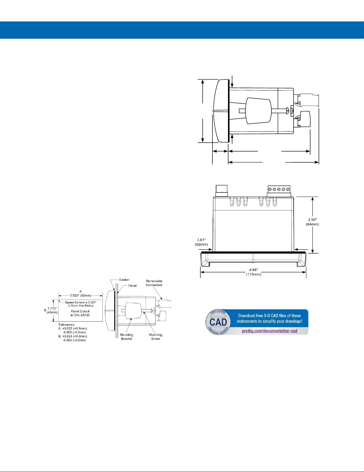
Figure 1. Panel Cutout and Mounting
Mounting Dimensions
Figure 2. Meter Dimensions – Side View
Figure 3. Case Dimensions – Top View
1.76"
(45mm)
0.59"
(15mm)
3.2"
(81mm)
2.45"
(62mm)
3.6"
(91mm)
Page 13
Trident Series PD765 Process & Temperature Meters
Instruction Manual
13
Connections
All connections are made to removable screw
terminal connectors located at the rear of the meter.
• Use copper wire with 60°C or 60/75°C insulation
for all line voltage connections. Observe all safety
regulations. Electrical wiring should be performed
in accordance with all applicable national, state,
and local codes to prevent damage to the meter
and ensure personnel safety.
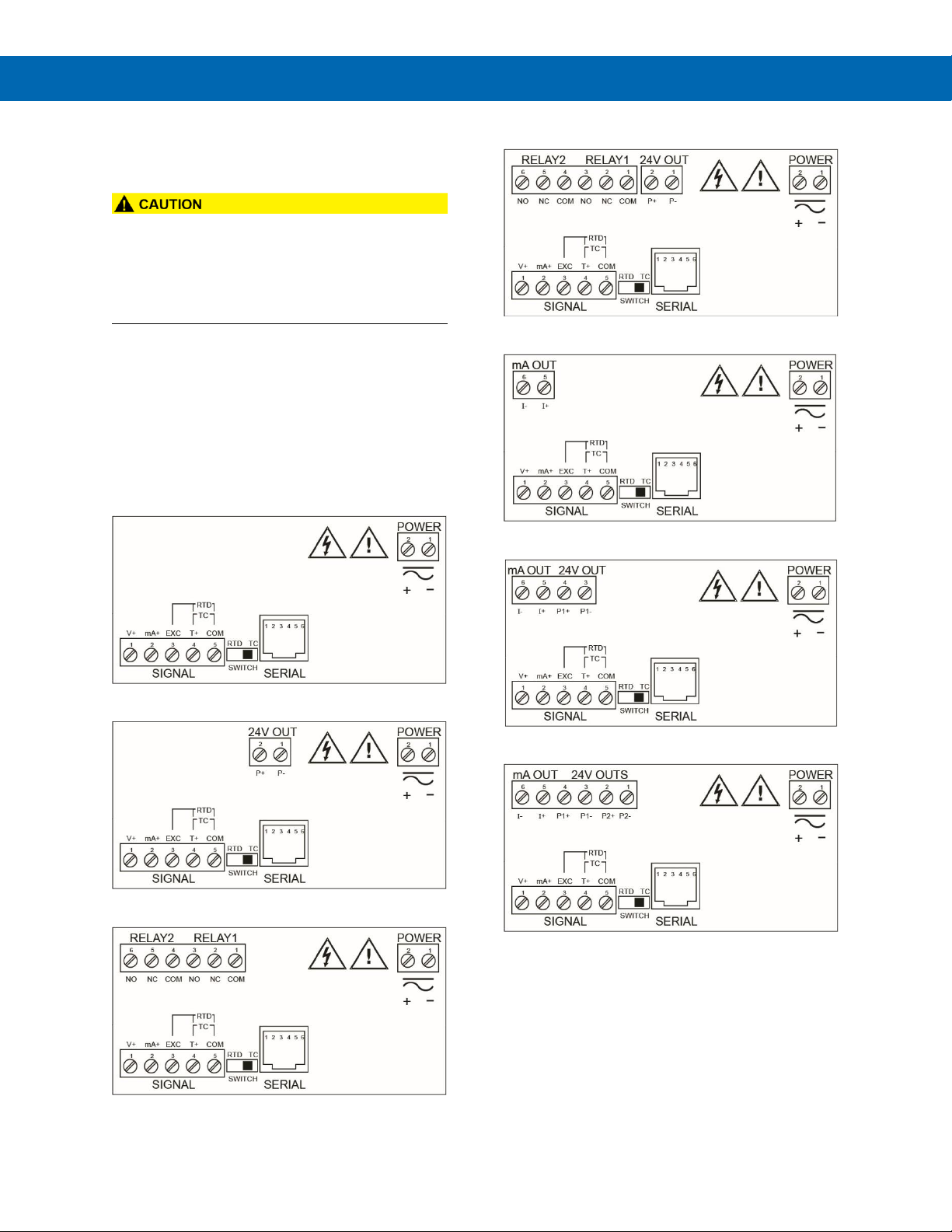
Connector Labeling
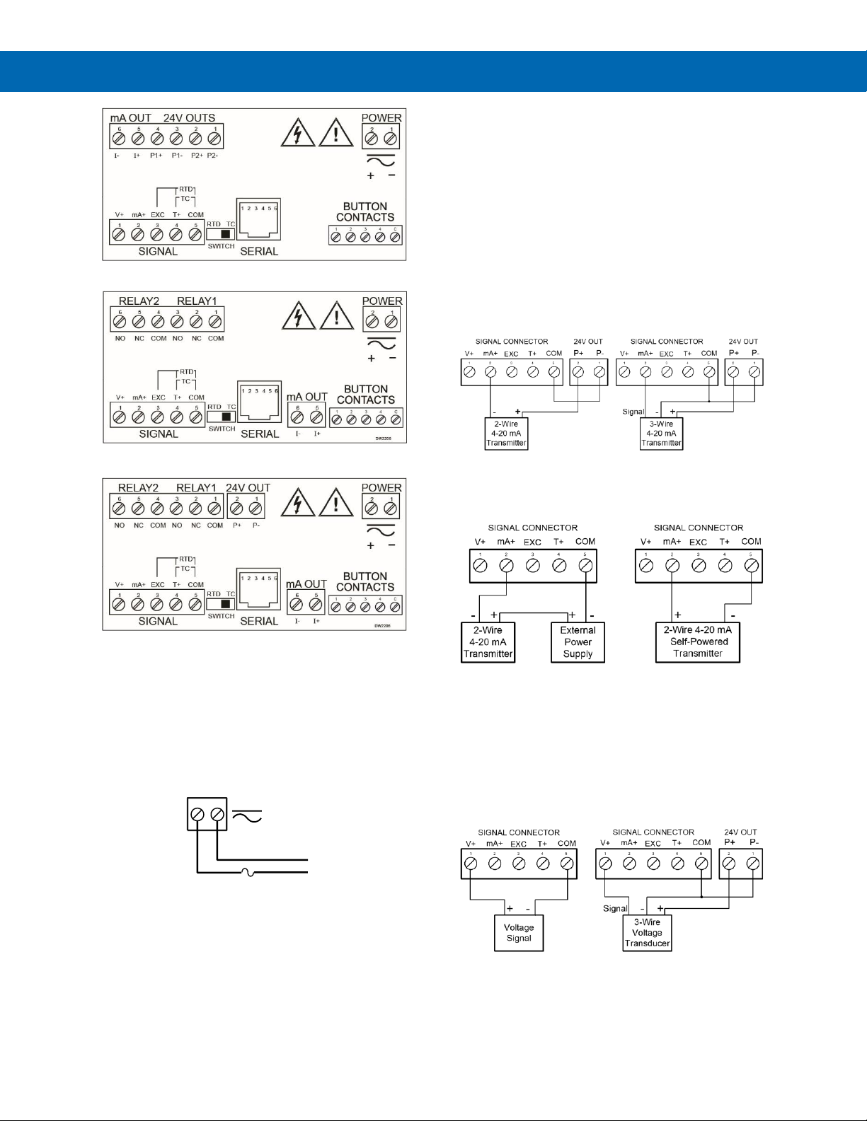
The connectors label, affixed to the meter, shows the
location of all connectors available with requested
configuration. It also identifies the location of the
RTD/TC selector switch. The images below show all
connector configurations for the PD765. Note that the
connector in the upper left of the diagram has different
configurations based on the model.
Note: # on the following figures refers to power options.
(Example: PD765-6R0-00)
Figure 4. Connector Labeling for PD765-#R0-00
Figure 5. Connector Labeling for PD765-6R0-10
Figure 6. Connector Labeling for PD765-#R2-00
Figure 7. Connector Labeling for PD765-6R2-10
Figure 8. Connector Labeling for PD765-#R3-00
Figure 9. Connector Labeling for PD765-6R3-10
Figure 10. Connector Labeling for PD765-6R3-20
Page 14
Trident Series PD765 Process & Temperature Meters
Instruction Manual
14
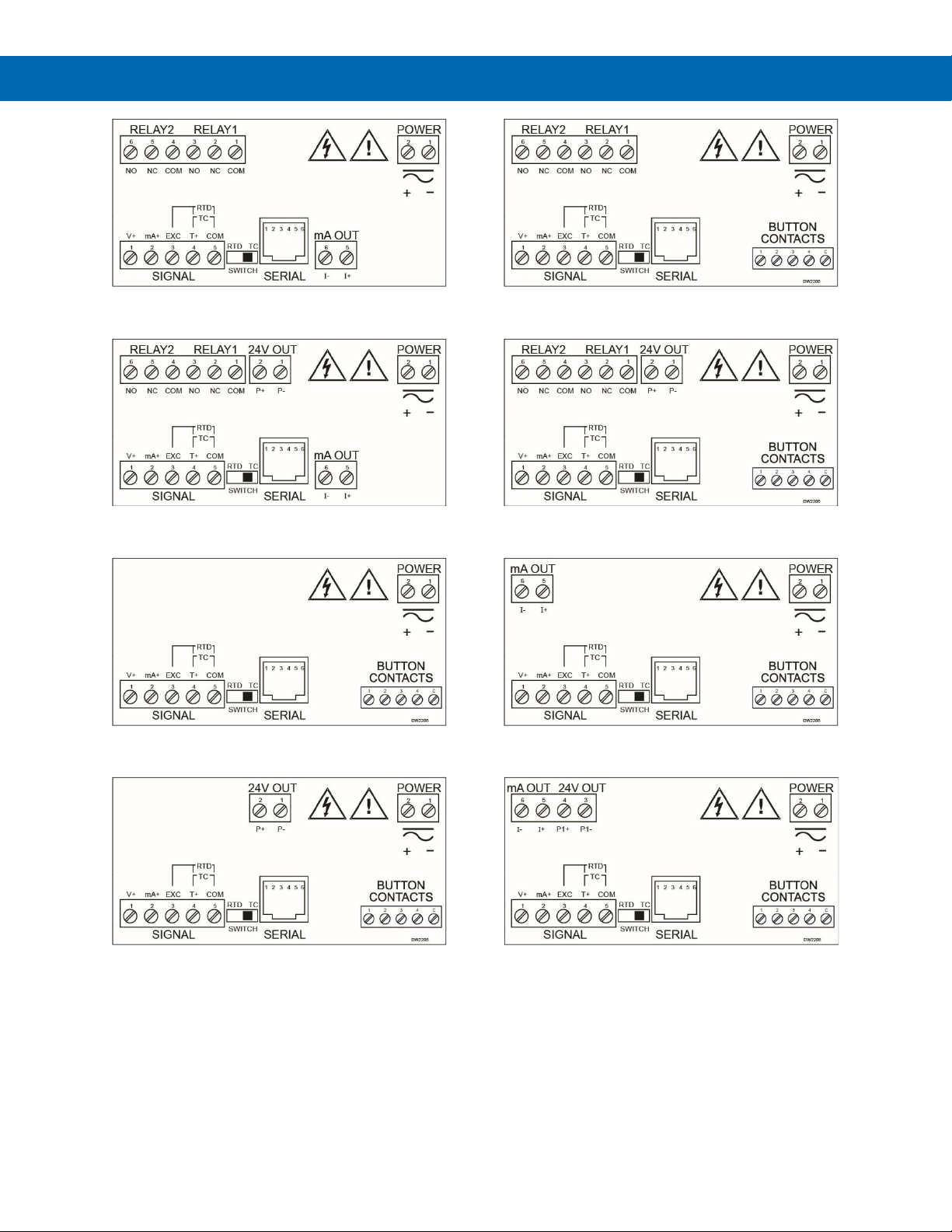
Figure 11. Connector Labeling for PD765-7R5-00
Figure 12. Connector Labeling for PD765-6R5-10
Figure 13. Connector Labeling for PD765-#X0-00
Figure 14. Connector Labeling for PD765-6X0-10
Figure 15. Connector Labeling for PD765-#X2-00
Figure 16. Connector Labeling for PD765-6X2-10
Figure 17. Connector Labeling for PD765-#X3-00
Figure 18. Connector Labeling for PD765-6X3-10
Page 15
Trident Series PD765 Process & Temperature Meters
Instruction Manual
15
Figure 19. Connector Labeling for PD765-6X3-20
Figure 20. Connector Labeling for PD765-7X5-00
Figure 21. Connector Labeling for PD765-6X5-10
Power Connections
Power connections are made to a two-terminal
connector labeled POWER on Figures 4-21. See
Connector Labeling on page 13. The meter will
operate regardless of DC polarity connection. The +
and - symbols are only a suggested wiring convention.
Figure 22. Power Connections
Signal Connections
Signal connections are made to a five-terminal
connector labeled SIGNAL shown in Figures 4-21.
See page 13. Connector Labeling. The COM
(common) terminal is the return for all types of input
signals.
Current and Voltage Connections
The following figures show examples for current and
voltage connections.
There are no switches or jumpers to set up for current
and voltage inputs. Setup and programming is
performed through the front panel buttons.
Figure 23. Transmitter Powered by Internal Supply
(Optional)
Figure 24. Transmitter Powered by External Supply
or Self-Powered
The current input is protected against current
overload by a resettable fuse. The display may or
may not show a fault condition depending on the
nature of the overload.
The fuse limits the current to a safe level when it
detects a fault condition, and automatically resets
itself when the fault condition is removed.
Figure 25. Voltage Input Connections
The meter is capable of accepting any voltage from
-10 VDC to +10 VDC.
12
AC or DC
POWER
Required External Fuse:
5 A max, Slow Blow
POWER CONNECTOR
+ -
Page 16
Trident Series PD765 Process & Temperature Meters
Instruction Manual
16
Thermocouple and RTD
Connections
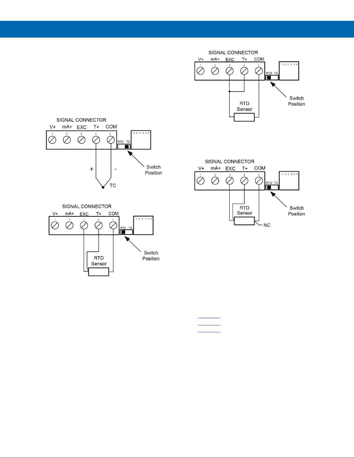
The following figures show examples for
thermocouple and RTD connections.
The RTD/TC selector switch must be set to the proper
position for the meter to accept the selected
temperature input.
The input type is selected using the Setup menu.
The selected thermocouple input must correspond to
the thermocouple sensor and wire type used.
Figure 26. Thermocouple Input Connections
Figure 27. Three-Wire RTD Input Connections
The meter accepts two, three, or four-wire RTDs. The
three-wire RTD connection has built-in lead wire
compensation.
Figure 28. Two-Wire RTD Input Connections
Lead wire compensation for two-wire RTDs can be
applied using the Adjust menu. See Offset Adjustment
(Adj) on page 32.
Figure 29. Four-Wire RTD Input Connections
The four-wire RTD connection is similar to the threewire. One of the leads of a four-wire RTD is not
connected and may be clipped off.
The three-wire connection provides sufficient lead
wire compensation to provide accurate readings even
with long leads.
Serial Communication
Serial communication connection is made to an RJ11
connector labeled SERIAL. See Figures under
Connector Labeling on page 13.
Use PDA7232 for RS-232 interfacing.
Use PDA7422 for RS-485 interfacing.
Use PDA7420 for meter-to-meter interfacing for
cloning purposes (i.e. copying programmed settings
from one meter to other meters).
Page 17
Trident Series PD765 Process & Temperature Meters
Instruction Manual
17
Relays and 24 V Output
Connections
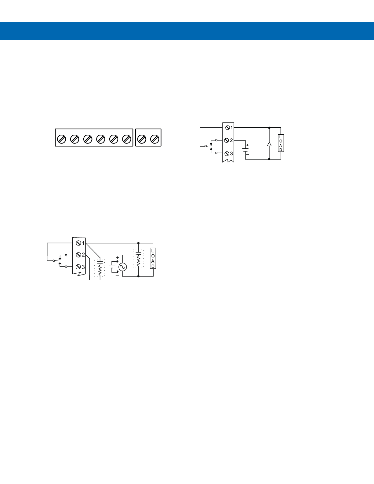
Relay connections are made to a six-terminal
connector labeled RELAY1, RELAY2. See Figures
under Connector Labeling on page 13. The COM
(common) terminals of the relays should not be
confused with the COM (common) terminal of the
SIGNAL connector. The 24 VDC output is available at
the connector labeled 24V OUT, next to the relays
connector.
Figure 30. Relay & 24 V Output Connections
Switching Inductive Loads
The use of snubbers to suppress electrical noise is
strongly recommended when switching inductive loads
to prevent disrupting the microprocessor’s operation.
The snubbers also prolong the life of the relay contacts.
Suppression can be obtained with resistor-capacitor
(RC) networks assembled by the user or purchased as
complete assemblies. Refer to the following circuits for
RC network assembly and installation:
Figure 31. AC and DC Loads Protection
Choose R and C as follows:
R: 0.5 to 1 for each volt across the contacts
C: 0.5 to 1 µF for each amp through closed contacts
Notes:
1. Inductive relay rating is 1/14 HP (50 W) at
115/230 VAC
2. Use capacitors rated for 250 VAC.
3. RC networks may affect load release time of
solenoid loads. Check to confirm proper
operation.
4. Install the RC network at the meter's relay screw
terminals. An RC network may also be installed
across the load. Experiment for best results.
Figure 32. Low Voltage DC Loads Protection
RC Networks Available from
Precision Digital
RC networks are available from Precision Digital and
should be applied to each relay contact switching an
inductive load. Part number: PDX6901.
Note: Relays are de-rated to 1/14th HP (50 watts)
with an inductive load.
24V OUT
P+ P-COM NONO NC NC COM
RELAY2 RELAY1
4 36 5 2 1 2 1
C
R
C
R
Use a diode with a
reverse breakdown
voltage two to three
times the circuit voltage
and forward current at
least as large as the
load current.
Page 18
Trident Series PD765 Process & Temperature Meters
Instruction Manual
18
4-20 mA Output & Input Signal
Connections
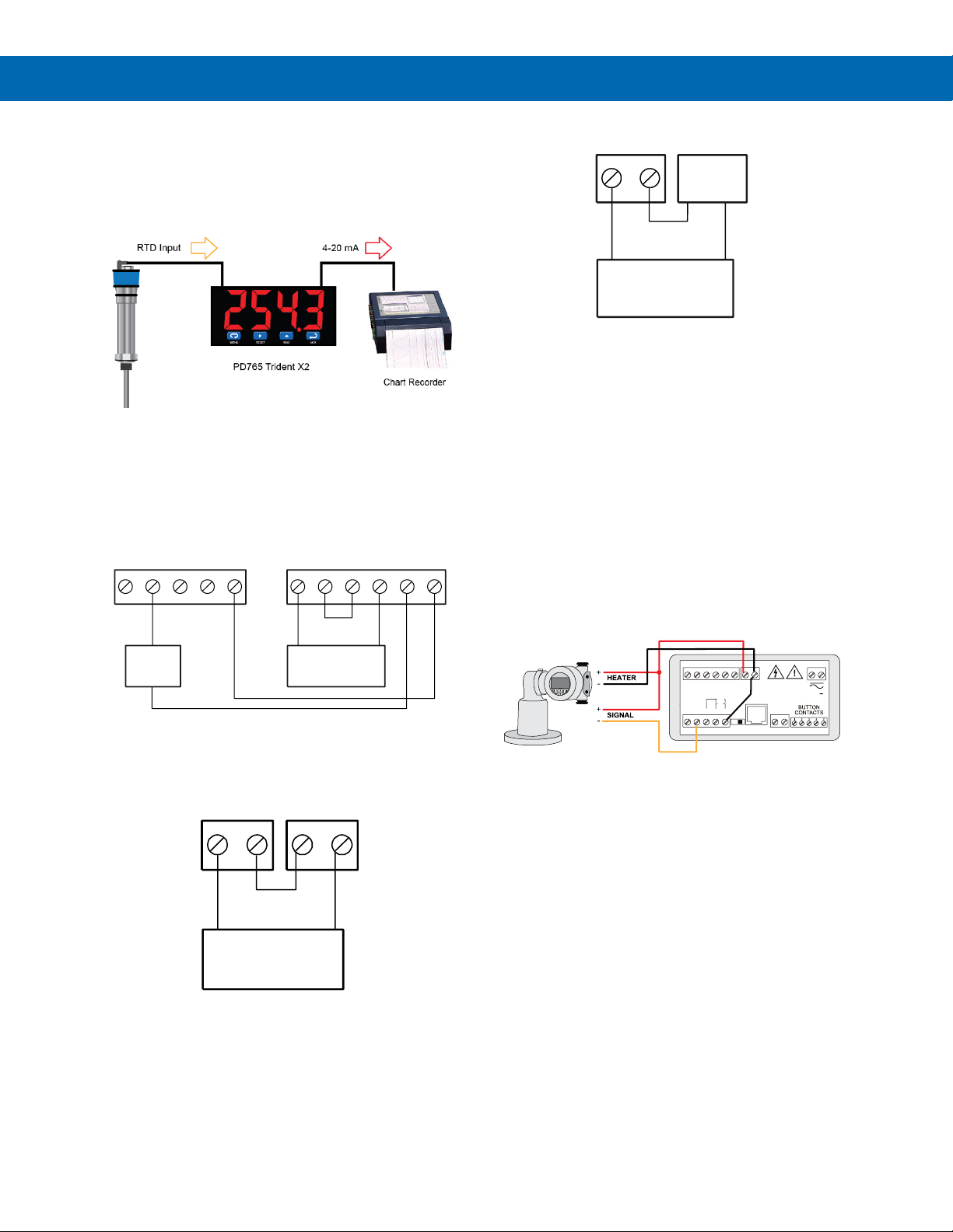
The Trident X2, with an optional 4-20 mA output, can
be used as an isolated temperature transmitter with a
big display by converting the thermocouple or RTD input into an isolated 4-20 mA output.
Connections for the 4-20 mA transmitter output are
made to the connector terminals labeled
“mA OUT: I-, I+”. The 4-20 mA output may be
powered from an internal power supply (optional) or
from an external power supply.
Figure 33. 4-20 mA Output & Input Signal
Powered by Meter
Models include PD765-6R3-20 and PD765-6X3-20
Figure 34. 4-20 mA Output Powered by Meter
Models include PD765-6R5-10, PD765-6X5-10
Figure 35. 4-20 mA Output Powered Externally
Models include PD765-6R3-00, PD765-6X3-00,
PD765-7R3-00, PD765-7X3-00, PD765-7R5-00,
PD765-7X5-00
Other Uses for Transmitter Power
Supplies
The most common use for the Trident’s two power
supplies is for the 200 mA transmitter power supply to
power the field transmitter and the other power supply
to power the 4-20 mA output from the meter.
However, the power supplies can be used in other
ways. For instance, for level transmitters that require
the use of a heated lens, the Trident’s 200 mA power
supply could be used to power both the heated lens
and the 4-20 mA signal from the transmitter.
Figure 36. Trident X2 Powers Both the Heater
and 4-20 mA Input Signal
COM
SIGNAL CONNECTOR
mA+
21 3 54
V+ T+
EXC
2-Wire
4-20 mA
Transmitter
-
+
I-
mA OUT
P2-P1+
45 3 12
P2+
P1-
24V OUT
6
I+
Remote Display,
Chart Recorder,
etc.
+
-
I-
mA OUT
56
I+
Remote Display,
Chart Recorder,
etc.
+
-
24V OUT
P+ P-
12
External
Power
Supply
-
+
I-
mA OUT
56
I+
Remote Display,
Chart Recorder,
etc.
+
-
DW2206
POWER
SIGNAL
EXC T+V+ mA+ COM
RTD
SWITCH
TC
SERIAL
TC
RTD
1 2 3 4 5 6
COM NONO NC NC CO M
RELAY2 RELAY1
4 36 5 2 1
3 41 2 5
2 1
+
I- I+
mA OUT
6 5
24V OUT
2 1
P+ P-
Page 19
Trident Series PD765 Process & Temperature Meters
Instruction Manual
19
Isolated 4-20 mA Signal
Splitters & Converters
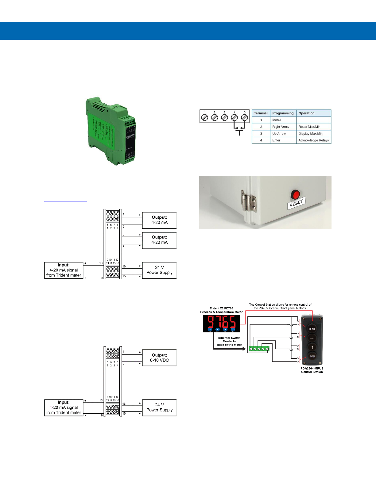
Precision Digital offers DIN rail mountable signal splitters and converters to spit the optional 4-20 mA signal
into two isolated 4-20 mA signals or into a 0-10 VDC
signal.
Isolated 4-20 mA Signal Splitter
The Trident’s optional 4-20 mA output can be split into
two isolated 4-20 mA signals by using the model
PD659-1MA-2MA 4-20 mA signal splitter.
Figure 37. Passive 4-20 mA Output from Trident Meter
Split into Two Isolated 4-20 mA Signals
4-20 mA to 0-10 VDC Signal
Converter
The Trident’s optional 4-20 mA output can be converted into a 0-10 VDC signal by using the model
PD659-1MA-1V 4-20 mA to 0-10 VDC signal converter.
Figure 38. Passive 4-20 mA Output from Trident Meter
Converted to 0-10 VDC Signal
External Button Contacts on
Trident X2
The Trident X2 is equipped with four external button
contacts that can be used to remotely operate the
Trident X2’s front panel buttons. For instance, these
button contacts can be used to program the meter
and to remotely acknowledge/reset the relays:
The external button contacts are particularly useful for
wiring up a remote button to reset the relays as
shown here:
Four-Position Control Station
for Remote Operation of Trident
PD765 X2 Buttons
The Trident PD765 X2's four programming and
operations buttons can be remotely controlled by
using the PDA2364-MRUE 4-button control station
accessory as shown in the diagram below.
Page 20
Trident Series PD765 Process & Temperature Meters
Instruction Manual
20
Setup and Programming
This section describes how to program the Trident
meter using the front panel buttons. The Trident meter
can also be programmed using Meterview Software
as described on page 35, or by copying the programing from meter to the next as described on page 34.
• There is no need to recalibrate the meter when
first received from the factory.
• The meter is factory calibrated prior to shipment,
for all input types, in milliamps, volts, and degrees.
The calibration equipment is certified to NIST
standards.
Overview
There are no jumpers involved in the setup process of
the meter. The RTD/TC selector switch, located
between the SIGNAL and SERIAL connectors, must
be set accordingly for the meter to accept RTD or
thermocouple inputs. See Figures under Connector
Labeling on page 13.
Setup and programming is done through the front
panel buttons.
After power and signal connections have been
completed and verified, apply power to the meter.
For Quick Interface Reference Guide
go to page 46.
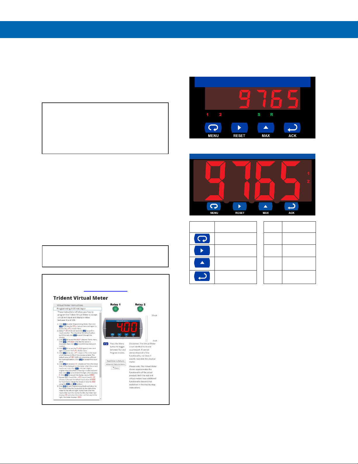
For Interactive Virtual Meter Demo visit
predig.com/tvm
Front Panel Buttons and Status
LED Indicators
Trident Standard Display
Trident X2 Display
Button
Symbol
Description
LED
Status
Menu
1 Alarm 1
Right arrow /
Reset
2 Alarm 2
Up arrow / Max
S*
Set point
indicator
Enter / Ack
R*
Reset point
indicator
*S and R indicators do not appear on X2 versions.
• Press the Menu button to enter or exit the
Programming Mode at any time.
• Press the Right arrow button to move to the next
digit during digit programming.
• Press the Up arrow button to scroll through the
menus, decimal point, or to increment the value
of a digit.
• Press the Enter/Ack button to access a menu or
to accept a setting.
• Press the Right arrow and Menu button
simultaneously or hold the Menu button for
approximately 3 seconds to access the Advanced
Features Menu of the meter.
Page 21

Trident Series PD765 Process & Temperature Meters
Instruction Manual
21
Display Functions and Messages
The meter displays various functions and messages
during setup/programming and operation. The
following table shows the displayed functions and
messages with their action/setting description.
Display
Parameter
Action/Setting
setu
Setup
Enter Setup menu
inpt
Input
Enter Input menu
4-20
4-20 mA
Set meter for 4-20 mA
input
0-10
0-10 VDC
Set meter for 10 VDC
input
rtd
RTD
Set meter for RTD input
a385
Alpha 385
Set = 0.00385
European curve 100
RTD
A392
Alpha 392
Set = 0.00392
American curve 100
RTD
tC
TC
Set meter for TC input
0 J
0 J
Type J
1 k
1 K
Type K
2 T
2 T
Type T
3 t.0
3 T.0
Type T, 0.1 resolution
4 E
4 E
Type E
f C
F or C
Set temperature scale
F
F
Set meter to Fahrenheit
C
C
Set meter to Celsius
dec.p
Decimal point
Set decimal point
prog
Program
Enter the Program menu
scal
Scale
Enter the Scale menu
Cal
Calibrate
Enter the Calibrate
menu
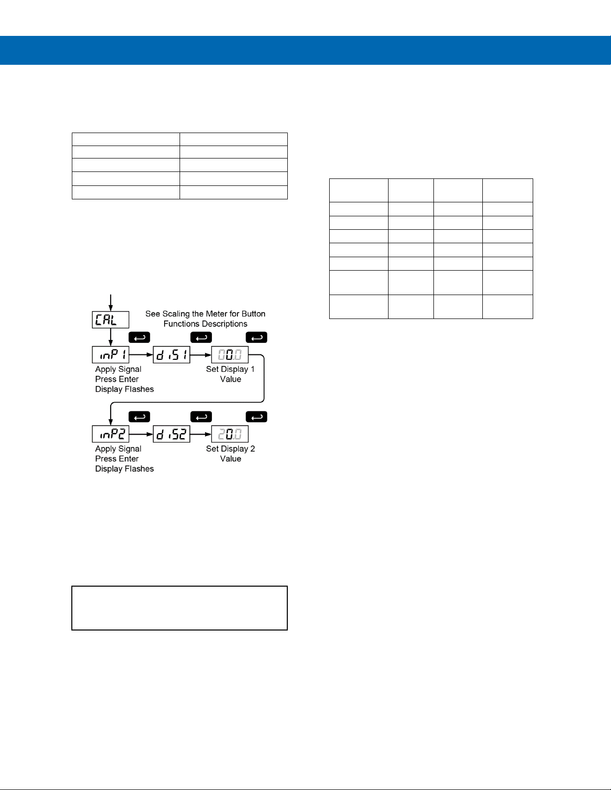
inp1
Input 1
Calibrate input 1 signal
or program input 1 value
dis1
Display 1
Program display 1 value
inp2
Input 2
Calibrate input 2 signal
or program input 2 value
dis2
Display 2
Program display 2 value
err
Error
Error, calibration not
successful, check signal
RELY
Relay
Enter the Relay menu
RLY1
Relay 1
Relay 1 setup
Act1
Action 1
Set relay 1 action
(automatic, latching, etc.)
Auto
Automatic
Set relay for automatic
reset
A-m
Auto-manual
Set relay for automatic +
manual reset any time
LtCH
Latching
Set relay for latching
operation
L-CL
Latchingcleared
Set relay for latching
operation with manual
reset only after alarm
condition has cleared
Altr
Alternate
Set relays for pump
alternation control
oFF
Off
Disable relay and front
panel status LEDs
Disable relay’s fail-safe
operation
Display
Parameter
Action/Setting
Set1
Set 1
Program set point 1
rSt1
Reset 1
Program reset point 1
RLY2
Relay 2
Setup relay 2
Act2
Action 2
Set relay 2 action
(automatic, latching, etc.)
Set2
Set 2
Program set point 2
RSt2
Reset 2
Program reset point 2
FLSF
Fail-safe
Enter Fail-safe menu
FLS1
Fail-safe1
Set relay 1 fail-safe
operation
on
On
Enable fail-safe
operation
off
Off
Disable fail-safe
operation
FLS2
Fail-safe2
Set relay 2 fail-safe
operation
DLAY
Delay
Enter Time Delay menu
DLY1
Delay 1
Enter relay 1 time delay
setup
On1
On 1
Set relay 1 On time
delay
OFF1
Off 1
Set relay 1 Off time
delay
DLY2
Delay 2
Enter relay 2 time delay
setup
On2
On 2
Set relay 2 On time
delay
OFF2
Off 2
Set relay 2 Off time
delay
brek
Break
Set RTD/TC input break
relay behavior
Brk1
Relay 1 Break
Set relay 1 input break
relay behavior
Off
Off
Set relay to non-alarm
condition at break
On
On
Set relay to alarm
condition at break
Brk2
Relay 2 Break
Set relay 2 input break
relay behavior
Aout
Analog output
Enter the Analog output
menu
Scal
Scale
Enter the Scale menu
Dis1
Display 1
Program display 1 value
out1
Output 1
Program output 1 value
(e.g. 4 mA)
Dis2
Display 2
Program display 2 value
out2
Output 2
Program output 2 value
(e.g. 20 mA)
SEbr
Sensor break
Program TC or RTD
sensor break value for
analog out
pass
Password
Enter the Password
menu
unlC
Unlocked
Program password to
lock meter
loCd
Locked
Enter password to
unlock meter
9999
-1999
open
Flashing
display
Overrange condition
Underrange condition
Open TC or RTD sensor
Page 22
Trident Series PD765 Process & Temperature Meters
Instruction Manual
22
Main Menu
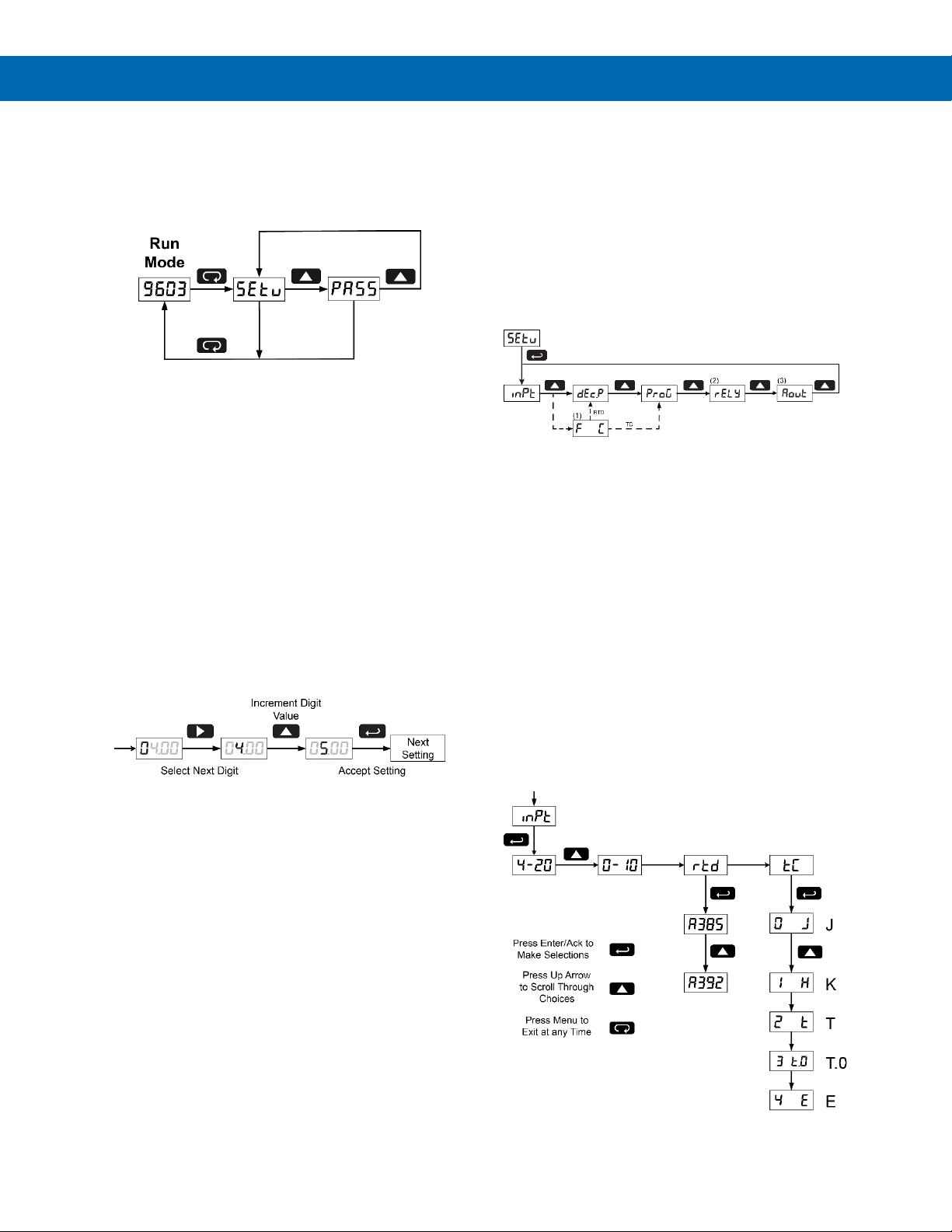
The main menu consists of the most commonly used
functions: Setup and Password.
• Press Menu button to enter Programming Mode
then press Up arrow button to scroll main menu.
• Press Menu, at any time, to exit and return to
Run Mode. Changes made to settings prior to
pressing Enter/Ack are not saved.
• Changes to the settings are saved to memory
only after pressing Enter/Ack.
• The display moves to the next menu every time a
setting is accepted by pressing Enter/Ack.
Setting Numeric Values
The numeric values are set using the Right and Up
arrow buttons. Press Right arrow to select next digit
and Up arrow to increment digit value.
The digit being changed is displayed brighter than the
rest.
Press the Enter/Ack button, at any time, to accept a
setting or Menu button to exit without saving changes.
The decimal point is set using the Up arrow button in
the Setup-decimal point menu.
Setting Up the Meter (setu)
The Setup menu is used to select:
1. Input signal the meter will accept
2. Decimal point position for process inputs
3. Units (F or C) for temperature inputs
4. Relay operation
5. 4-20 mA analog output setup
Press the Enter/Ack button to access any menu or
press Up arrow button to scroll through choices.
Press the Menu button to exit at any time.
Notes:
1. Selecting RTD or TC mode from the Input menu will include
the Fahrenheit/Celsius menu in the setup menu structure.
RTD will allow the selection of a decimal point location after
this menu and TC has a fixed decimal point location and will
not allow the selection of a decimal point location.
2. Relay menu is always available even if relays option is not
installed. Visual alarm indication is available through front
panel LEDs and MeterView software.
3. Analog Output menu is available if selected in the Advanced
Features menu. 4-20 mA output option board is installed and
set up at the factory.
Setting the Input Signal (inpt)
Enter the Input menu to set up the meter to display
current (4-20), voltage (0-10), thermocouple (tC), or
RTD (rtd) inputs.
The voltage input is capable of accepting any signal
from -10 to +10 VDC. Select voltage input to accept
0-5, 1-5, 0-10, or 10 VDC signals.
The current input is capable of accepting any signal
from -20 to 20 mA. Select current input to accept 0-20
or 4-20 mA signals.
Page 23
Trident Series PD765 Process & Temperature Meters
Instruction Manual
23
If RTD is selected, the display shows A385 or A392.
Select the coefficient to match the RTD sensor, either
0.00385 (A385, European curve) or 0.00392 (A392,
American curve). The display then shows the decimal
point menu, DEc.P. Select the decimal point resolution
as shown on page 23.
If TC is selected, scroll through the thermocouple
types and select the type matching the TC sensor.
The input signal must be connected to the appropriate
input terminals and the RTD/TC selector switch must
be set, see Figure 26. Thermocouple Input
Connections on page 16.
For thermocouple inputs, allow at least 30
minutes warm-up time for meter to reach
specified accuracy.
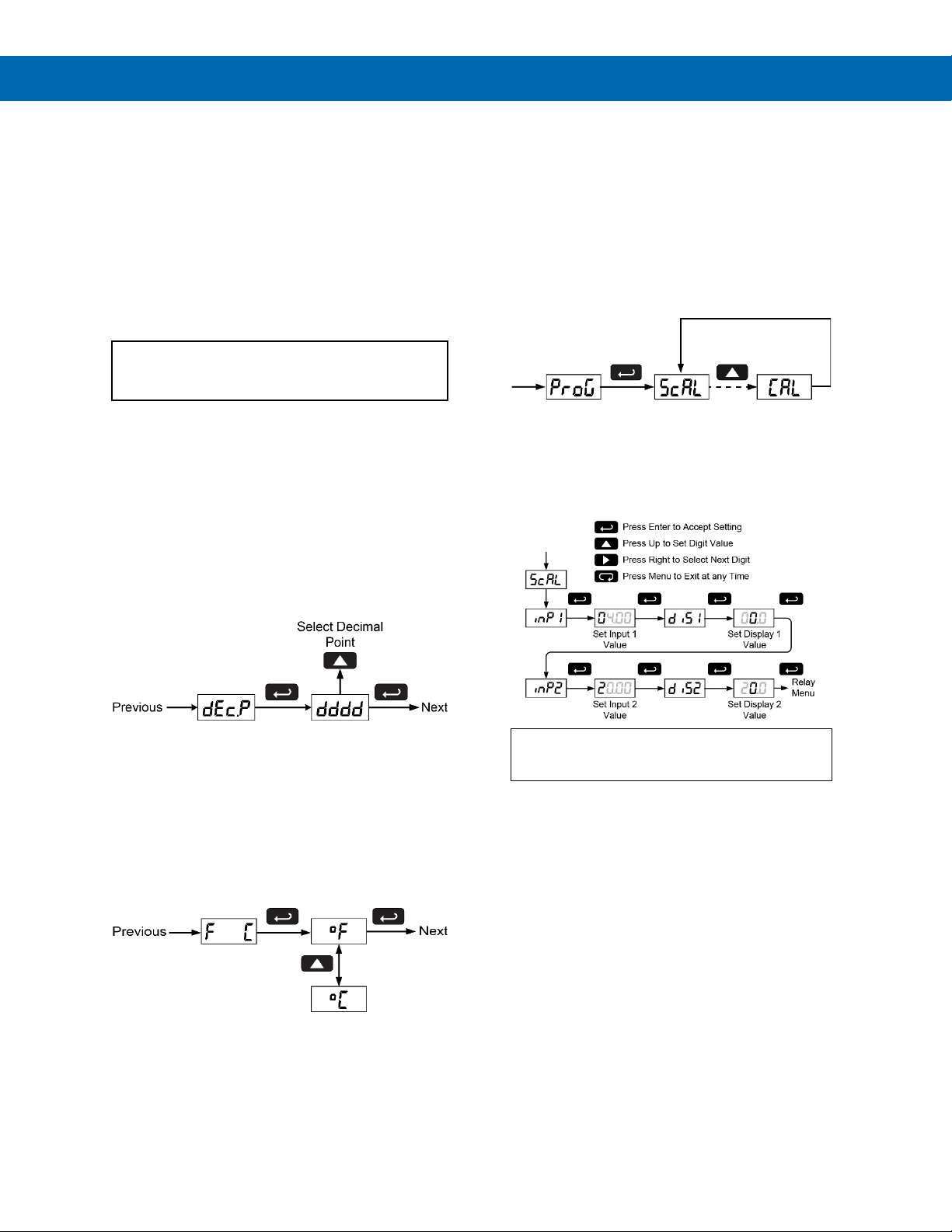
Setting the Decimal Point (dc.pt)
The decimal point for process inputs may be set with up
to three decimal places or with no decimal point at all.
The decimal point for RTD inputs may be set with
1 decimal place or none.
The decimal point for thermocouple inputs is fixed per
input selection.
Pressing the Up arrow moves the decimal point one
place to the right until no decimal point is displayed,
it then moves to the leftmost position.
Setting the Temperature Scale
(F C)
Meters with a thermocouple or RTD input can be set
to display temperature in degrees Fahrenheit or
Celsius.
Press Up arrow to change selection.
Press Enter/Ack to accept.
Programming the Meter (prog)
The meter may either be scaled (ScAL) without
applying an input or calibrated (Cal) by applying an
input. The meter comes factory calibrated to NIST
standards, so for initial setup, it is recommended to
use the (ScAL) function.
The Program menu contains the Scale (ScAL) and the
Calibrate (Cal) menus.
Process inputs may be scaled or calibrated to any
display within the range of the meter.
Scaling the Meter (scal)
The process inputs (4-20 mA and 10 VDC) can be
scaled to display the process in engineering units.
A signal source is not needed to scale the meter;
simply program the inputs and corresponding display
values.
For instructions on how to program numeric
values see Setting Numeric Values, page 22.
Note: The Scale menu is not available for
temperature inputs.
Error Message (Err)
An error message indicates that the calibration or
scaling process was not successful.
After the error message is displayed, the meter
reverts to input 1, allowing the appropriate input
signals to be applied.
The error message might be caused by any of the
following conditions:
1. Input signal is not connected to the proper
terminals or it is connected backwards.
2. Wrong signal selection in Setup menu.
3. Minimum input span requirements not
maintained.
4. Input 1 signal inadvertently applied to calibrate
input 2.
Page 24
Trident Series PD765 Process & Temperature Meters
Instruction Manual
24
Minimum Input Span
The minimum input span is the minimum difference
between input 1 and input 2 signals required to
complete the calibration or scaling of the meter.
Input range
Input 1 & input 2 span
4-20 mA
0.40 mA
10 VDC
0.20 VDC
TC
100F (56C)
RTD
50F (28C)
Calibrating the Meter (Cal)
The meter can be calibrated to display the process in
engineering units by applying the appropriate input
signals and following the calibration procedure.
The use of a calibrated signal source is required to
calibrate the meter.
Recalibrating Temperature Inputs
(Cal)
Remember, the meter is calibrated at the factory
prior to shipment. Recalibration is recommended at
least every twelve months.
The Calibration (CAL) menu is used to recalibrate the
thermocouple and RTD inputs.
Allow at least 30 minutes warm-up time before
performing recalibration procedure to ensure
specified accuracy.
Recommended Calibration Points
To recalibrate the meter, it is recommended to use
the Fahrenheit scale; this will give a greater degree of
accuracy to the calibration. The scale can be changed
to the Celsius scale after calibration is completed. The
meter will display temperature accurately in any scale.
The following table shows the recommended low and
high calibration points for all types.
Type of
input
Input 1
(Low)
Input 2
(High)
Check
(Middle)
Type J T/C
32F
1182F
600F
Type K T/C
32F
1893F
960F
Type T T/C
32F
693F
360F
Type T T/C
32.0F
693.0F
360.0F
Type E T/C
32F
1652F
840F
100 RTD
(0.00385)
32F
100
1148F
320.12
590F
215.61
100 RTD
(0.00392)
32F
100
1127F
320.89
580F
215.87
Recalibration Procedure for
Temperature Inputs
1. Connect signal to the meter using the
appropriate wire (e.g. type J thermocouple
wire to recalibrate type J input), see page 16.
2. Set up the meter to accept the selected input
(e.g. type J T/C), see page 22.
3. Set up the meter to display temperature in
degrees Fahrenheit, see page 23.
4. Apply signal corresponding to input 1 (32°F)
and program display 1 to 32, see page 24.
5. Apply signal corresponding to input 2
(1182°F for type J) and program display 2
accordingly, see page 24.
6. After the meter accepts input 2, the display
flashes the message CJr that indicates the
meter is sensing the cold junction reference.
This completes the recalibration procedure
for the selected input.
Recalibrating Process Inputs (ICal)
The Internal Calibration (ICAL) menu, located in the
Advanced features menu, is used to recalibrate the
current and voltage inputs. Recalibration is
recommended at least every twelve months.
Refer to Internal Calibration (ICal), page 41 for
instructions.
Page 25
Trident Series PD765 Process & Temperature Meters
Instruction Manual
25
Setting the Relay Operation (rely)
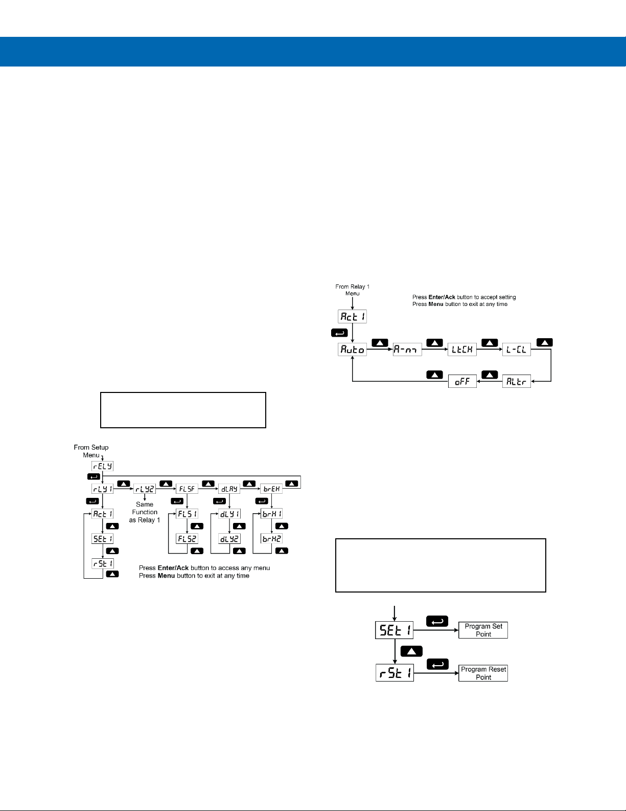
This menu allows you to set up the operation of the
relays:
1. Relay action (ACT)
a. Automatic reset only (non-latching)
b. Automatic + manual reset at any time
(non-latching)
c. Latching (manual reset only)
d. Latching with Clear (manual reset only
after alarm condition has cleared)
e. Pump alternation control (automatic
reset only)
f. Off (relay and status LED disabled)
2. Set point
3. Reset point
4. Fail-safe operation
a. On (enabled)
b. Off (disabled)
5. Time delay
a. On delay (0-199 seconds)
b. Off delay (0-199 seconds)
6. Break Condition Behavior
a. Off (non-alarm condition)
b. On (alarm condition)
Setting the Relay Action
The relays’ Action menu allows the user to set up the
operation of the relays. The relays may be set up for
any of the following modes of operation:
1. Automatic reset (non-latching)
2. Automatic + manual reset at any time (nonlatching)
3. Latching (manual reset only, at any time)
4. Latching with Clear (manual reset only after
alarm condition has cleared)
5. Pump alternation control (automatic reset
only)
6. Off (relay and status LED disabled)
The following graphic shows relay 1 action setup;
relay 2 is set up in a similar fashion.
Programming Set and Reset Points
High alarm indication: program set point above reset
point.
Low alarm indication: program set point below reset
point.
The deadband is determined by the difference
between set and reset points. Minimum deadband is
one display count. If set and reset points are
programmed the same, relay will reset one count
below set point.
Refer to page 21 for a description of
Display Functions and Messages
Quick Set Points
Press Up arrow and Menu at the same time to
access set/reset points quickly.
Page 26
Trident Series PD765 Process & Temperature Meters
Instruction Manual
26
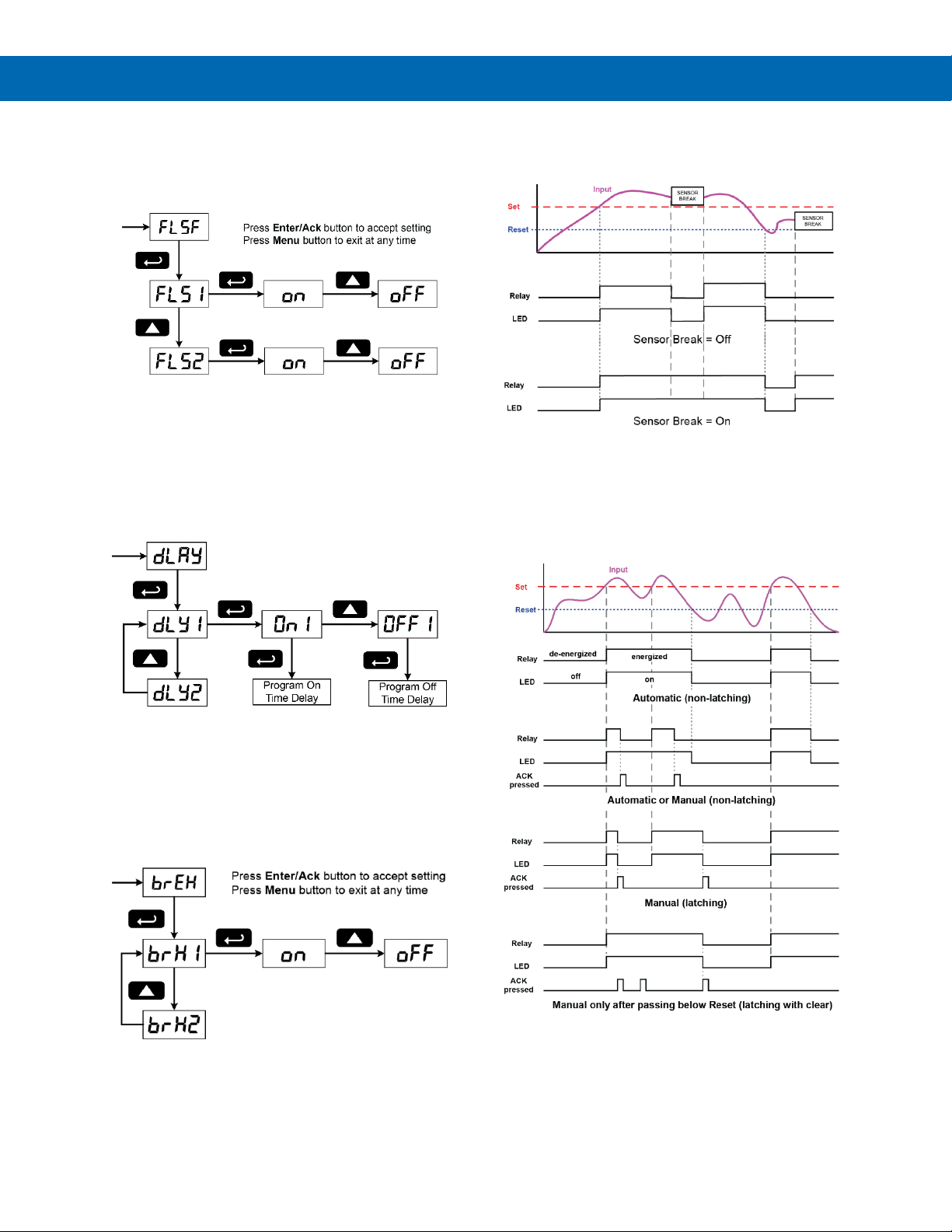
Setting Fail-Safe Operation
The fail-safe operation is set independently for each
relay. Select on to enable or select off to disable failsafe operation.
Programming Time Delay
The On and Off time delays may be programmed for
each relay between 0 and 199 seconds. The relays
will transfer only after the condition has been
maintained for the corresponding time delay.
The On time delay is associated with the set point.
The Off time delay is associated with the reset point.
Setting Sensor Break Condition
The sensor break relay condition may be
programmed for each relay as On (alarm) or Off (nonalarm). The relays will enter these states when a
sensor break is detected for RTD or thermocouple
inputs. These settings have no effect when current or
voltage inputs are selected.
Sensor Break Operation
The following graphs illustrate the operation of how
the meter reacts when a sensor break is detected.
Relay and Alarm Operation
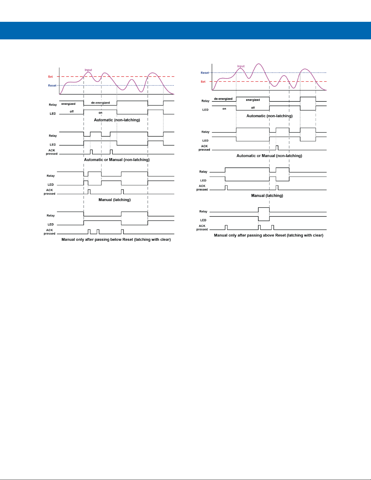
The following graphs illustrate the operation of the
relays, status LEDs, and ACK button.
High Alarm Operation (Set > Reset)
For Manual reset mode, ACK can be pressed anytime
to turn "off" relay. For relay to turn back "on", signal
must go below set point, and then go above it.
Page 27
Trident Series PD765 Process & Temperature Meters
Instruction Manual
27
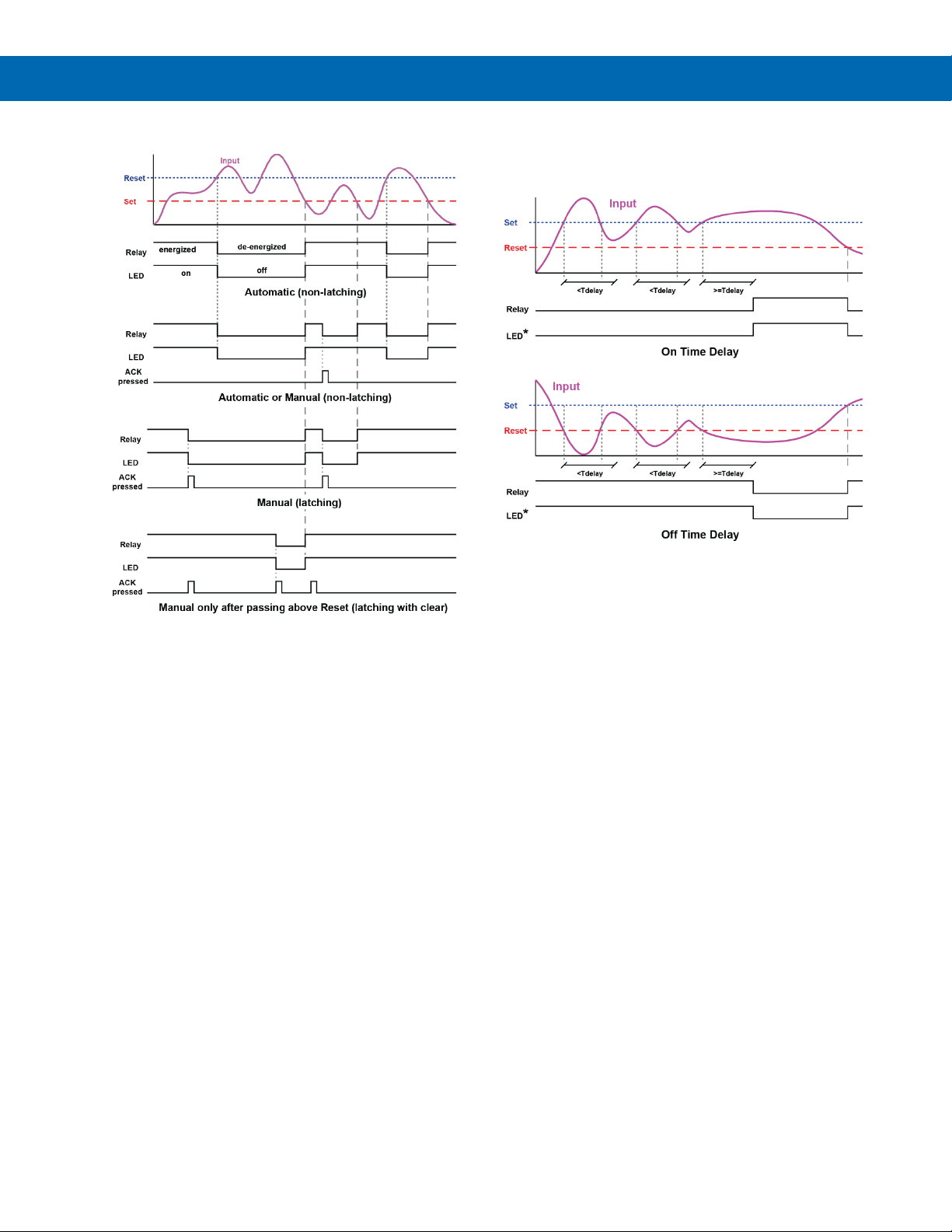
Low Alarm Operation (Set < Reset)
For Manual reset mode, ACK can be pressed anytime
to turn "off" relay. For relay to turn back "on", signal
must go above set point, and then go below it.
Time Delay Operation
The following graphs show the operation of the time
delay function.
If the signal crosses the set point, the On time delay
timer starts and the relay trips when the time delay
has elapsed. If the signal drops below the set point
(high alarm) before the time delay has elapsed, the
On time delay timer resets and the relay does not
change state. The same principle applies to the Off
time delay.
* Note: The LED is not affected by Time Delay when
“Automatic or Manual” reset mode is selected.
Rather the LED follows the set and reset points.
Page 28
Trident Series PD765 Process & Temperature Meters
Instruction Manual
28
High Alarm with Fail-Safe Operation
(Set > Reset)
Error! Reference source not found.
Low Alarm with Fail-Safe Operation
(Set < Reset)
Error! Reference source not found.
Page 29
Trident Series PD765 Process & Temperature Meters
Instruction Manual
29
Pump Controller with Dual-Pump Alternation
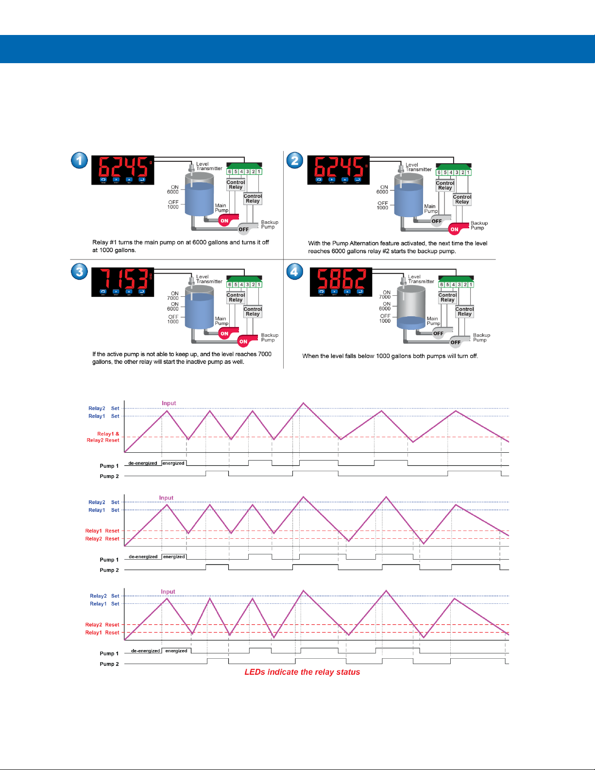
The PD765 can be used as a low-cost pump controller when combined with a continuous level transmitter. One of the most
common pump control application is shown below: controlling and alternating two pumps. The goal is to control the level
between 1000 and 6000 gallons. The main pump turns on when the level reaches 6000 gallons and pumps down to 1000
gallons and then shuts the pump off. The next cycle, the backup pump turns on at 6000 gallons and shuts off at 1000
gallons. If at any time the active pump can’t keep the level below 7000 gallons, the other pump would come on also.
Pump Alternation Control Operation
Page 30
Trident Series PD765 Process & Temperature Meters
Instruction Manual
30
Scaling the 4-20 mA Analog Output
(Aout)
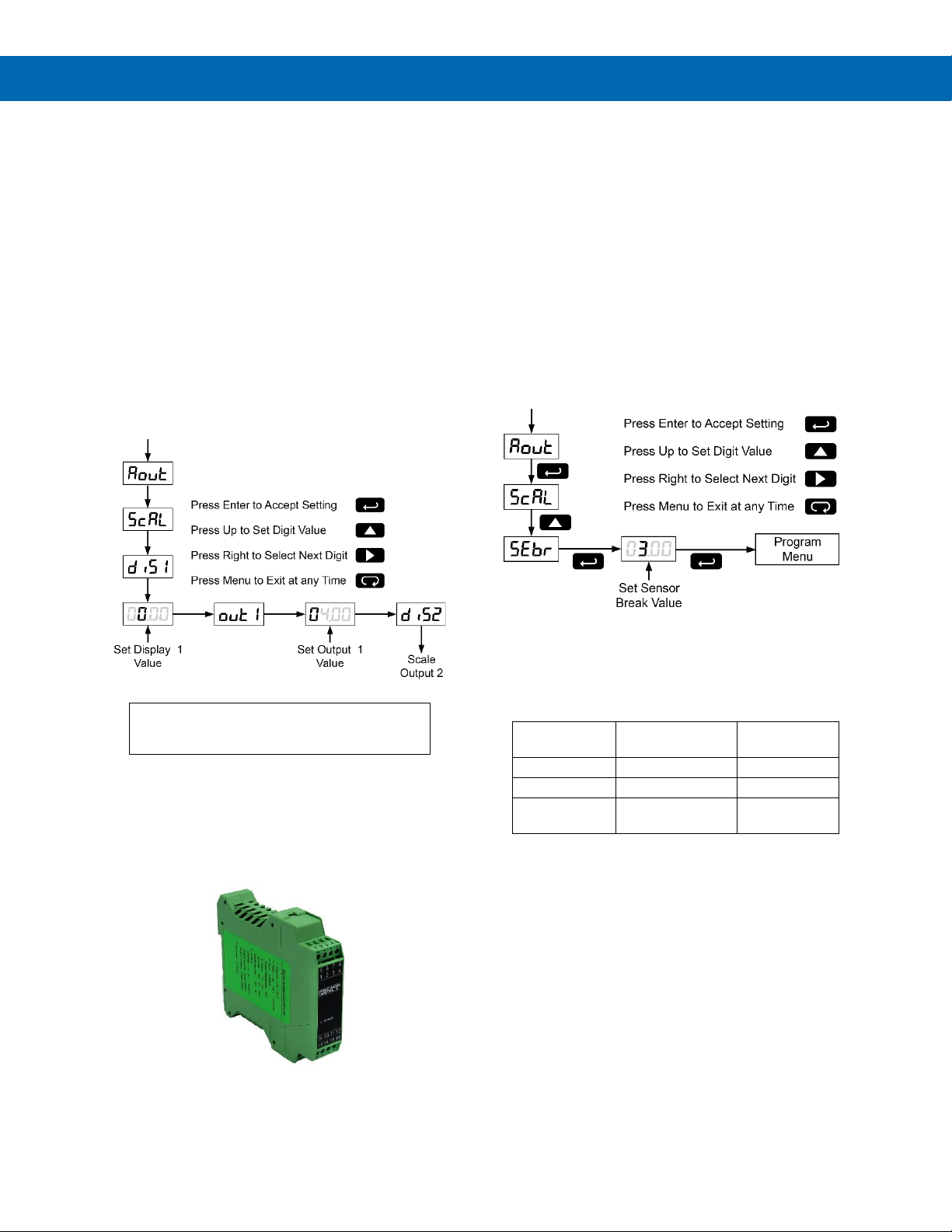
The 4-20 mA analog output can be scaled to provide
a 4-20 mA signal for any display range selected.
No equipment is needed to scale the analog output;
simply program the display values to the
corresponding mA output signal.
The Analog Output menu appears in the Setup menu
only on meters that are equipped with a 4-20 mA
output. This menu is enabled or disabled at the
factory via the Advanced Features menu. For more
information on the Advanced Features Menu see
page 31.
The Analog Output menu is used to program:
1. 4-20 mA output based on display values
2. Sensor break value in mA
For instructions on how to program numeric
values see Setting Numeric Values, page 22.
Isolated 4-20 mA Signal Splitters &
Converters
Precision Digital offers DIN rail mountable signal splitters and converters to spit the optional 4-20 mA signal
into two isolated 4-20 mA signals or into a 0-10 VDC
signal.
For more information see page 19.
Program the Sensor Break Output
Value (SEbr)
The sensor break value corresponds to the output
signal generated when the meter detects a sensor
break for thermocouple and RTD inputs.
For example if there is an open thermocouple, the
meter displays the message “open” and the analog
output goes to the programmed sensor break value
(e.g. 3.00 mA).
The sensor break value can be programmed from
0.00 to 23.99.
The typical output signal range is 1.00 to 23.00 mA
(e.g. If sensor break value is programmed to 0.00, the
actual output will not be greater than 1.00 mA).
Analog Output when Display is Out
of Range
The analog output reflects the display out of range
conditions as follows:
Input
Condition
Display
Analog
Output
Underrange
Flashing -1999
3.00 mA
Overrange
Flashing 9999
21.00 mA
Open TC or
RTD
Flashing open
Sensor break
value
Page 31
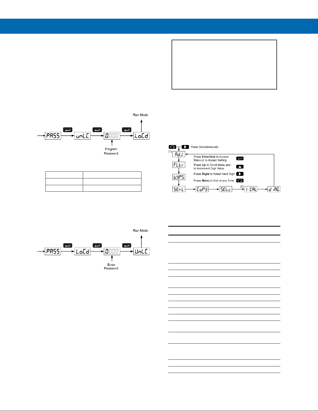
Trident Series PD765 Process & Temperature Meters
Instruction Manual
31
Setting Up the Password (pass)
The Password menu is used to program a four-digit
password to prevent unauthorized changes to the
programmed parameter settings.
Locking the Meter
Enter the Password menu and program a four-digit
password.
For instructions on how to program numeric values
see Setting Numeric Values, page 22.
Record the password for future reference. If
appropriate, it may be recorded in the space provided.
Model:
Serial Number:
Password:
__ __ __ __
Unlocking the Meter
If the meter is password protected, the correct
password must be entered in order to make changes
to the parameter settings.
Entering the correct four-digit number sets the
password to 0000, disabling the protection.
Changes to the programmed parameter settings are
allowed only with the password set to 0000.
If the password entered is incorrect, the meter
displays LoCd (Locked) for about two seconds, then it
returns to Run Mode. To try again, press Enter/Ack
while the Locked message is displayed.
Forgot the Password?
The password may be disabled by the following
procedure:
1. Note display reading prior to pressing the Menu
button. Ignore decimal point and sign.
2. Access the Password menu, add 2 to the noted
reading and enter that number as the password
(e.g. display reading = -1.23, password = 0125)
Advanced Features Menu
To simplify the setup process, functions not needed
for most applications are located in the Advanced
Features menu.
Press the Right arrow and Menu button
simultaneously or hold the Menu button for
approximately 3 seconds to access the Advanced
Features Menu of the meter.
1. Available for temperature inputs only
2. Available for process inputs only
Advanced Features Menu & Display
Messages
Display Functions and Messages
Display
Parameter
Action/Setting
adj
Adjust
Set offset adjustment for
temperature, not
available for process
inputs
fltr
Filter
Set noise filter value
byps
Bypass
Set filter bypass value
serl
Serial
Set serial communication
parameters
prot
Protocol
Enter the Protocol menu
PDC
PDC
Select PDC protocol
mbs
Modbus
Select Modbus protocol
addr
Address
Set meter address
baud
Baud rate
Select baud rate
trdE
Transmit delay
Set transmit delay for
serial communication
prty
Parity
Select none, even, or
odd (Modbus only)
tbyt
Byte-to-byte
Program byte-to-byte
timeout (silent time –
Modbus only)
Copy
Copy
Enter copy function
send
Send
Send meter settings to
Page 32

Trident Series PD765 Process & Temperature Meters
Instruction Manual
32
Display Functions and Messages
Display
Parameter
Action/Setting
another meter
done
Done
Copy function completed
Selc
Select
Enter the Select menu
(function, cutoff, out)
Func
Function
Select linear or square
root function
Linr
Linear
Set meter for linear function
Sqrt
Square root
Set meter for square root
extraction
cutF
Cutoff
Set low-flow cutoff
out
Output
Set meter for either relay
or analog output
(factory set only; only
included in certain models)
Aout
Analog output
Set meter for analog
output option
rEly
Relay
Set meter for relay option
Aout
Analog output
Enable or disable analog
output
(factory set only; only
included in certain models)
Yes
Yes
Enable analog output
no
No
Disable analog output
Inty
Intensity
Select display intensity
ICal
Initial calibration
Enter initial calibration for
process inputs
Curr
Current
Calibrating current input
I lo
I low
Calibrate low current
input
I Hi
I high
Calibrate high current
input
volt
Volt
Calibrating voltage input
Vlo
V low
Calibrate low voltage
input
VHi
V high
Calibrate high voltage
input
diag
Diagnostics
Display parameter
settings
led
LED
Test display
CJC
CJC
Display cold junction
compensation voltage
Cfg
CFG
Display meter
configuration
pts
Points
Display calibration points
for process inputs
RELY
Relays
Display relay settings
Aout
Analog output
Display analog output
settings
GoFF
Gain/offset
Display gain and offset
for process inputs
SErL
Serial
Display serial
communication settings
Info
Information
Display software version
and S/N information
Offset Adjustment (Adj)
This parameter allows the user to select an offset
adjustment to the temperature being displayed. Offset
adjustment values can be either positive or negative
and can be any number within 19.9. The offset
adjustment value is programmed through the Adjust
menu.
The offset adjustment feature can be useful to
compensate for errors due to thermocouple junctions
or excessive lead wire resistance in RTDs.
The offset adjustment value is automatically reset to
zero whenever the type of temperature sensor is
changed (i.e. Thermocouple type or RTD curve).
Celsius/Fahrenheit conversion of the offset
adjustment value is automatic, see note 2 below for
important limitations.
Notes:
1. Offset adjustment is available only when TC or
RTD input is selected.
2. If adjustment value is greater than 11C and the
temperature scale is changed to Fahrenheit, the
maximum applied adjustment will be 19.9F.
Noise Filter (fltr)
Most applications do not require changing this
parameter. It is intended to help attain a steady
display with an unsteady (noisy) input signal.
The field selectable noise filter averages any minor or
quick changes in the input signal and displays the
reading with greater stability.
Increasing the filter value will help stabilize the
display, however this will reduce the display response
to changes on the input signal.
The filter level may be set anywhere from 2 to 199.
Setting filter value to zero disables filter function, and
bypass setting becomes irrelevant.
Noise Filter Bypass (byps)
The meter can be programmed to filter small input
changes, but allow larger input changes to be
displayed immediately, by setting the bypass value
accordingly.
If the input signal goes beyond the bypass value, it
will be displayed immediately with no averaging done
on it.
The noise filter bypass value may be set anywhere
from 0.2 to 99.9. It corresponds to percentage of full
scale for process inputs and to degrees Fahrenheit for
temperature inputs.
Increasing the bypass value may slow down the
display response to changes on the input signal.
Page 33
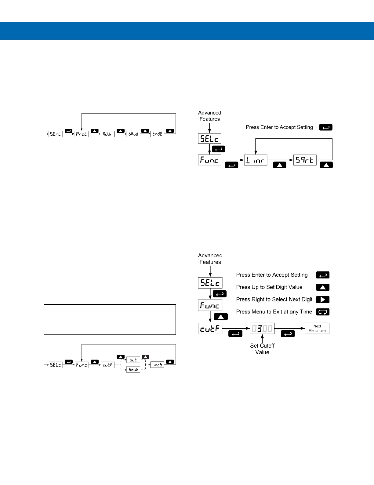
Trident Series PD765 Process & Temperature Meters
Instruction Manual
33
Serial Communications (serl)
The meter is equipped with serial communications
capability as a standard feature using PDC protocol
and MeterView software or using the Modbus RTU
protocol. The Modbus RTU protocol is included on all
models after 5/1/2010. To communicate with a
computer or other data terminal equipment, an RS232, RS-485, or USB adapter option is required; see
Ordering Information on page 6 for details.
When using more than one meter in an RS-485 multidrop mode, each meter must be provided with its own
unique address. The address may be programmed
from 00 to 99 for PDC protocol and from 1 to 247 for
Modbus protocol. The transmit delay may be set
between 0 and 199 ms (see Serial Communication
Adapter manual for more details).
The Trident can also be connected directly to another
Trident meter through a cable assembly (PDA7420).
This allows the user to copy all the settings from one
meter to another, using the Copy function.
Protocol Selection Menu (Prot)
The Protocol selection menu is used to select either
the PDC or the Modbus protocol. PDC protocol
should be selected to run MeterView software.
Select Menu (SElc)
The Select menu is used to select linear or square
root function, display intensity, and low-flow cutoff.
Selection for relay or analog output is a factory setting
depending on the option installed.
• Output options are installed and set up at the
factory.
• Changing the output selection will cause
erroneous operation.
Note: Depending on meter model, the Select menu will
display either out or Aout. In either case, the output selection
menu is for factory use only. Do not attempt to change
output selection.
Linear or Square Root Function
(linr or Sqrt)
Meters are set up at the factory for linear function.
The linear function provides a display that is linear
with respect to the input signal.
The square root function is used to linearize the signal
from a differential pressure transmitter and display
flow rate in engineering units.
Low-Flow Cutoff (cutF)
The low-flow cutoff feature allows the meter to be
programmed so that the often-unsteady output from a
differential pressure transmitter, at low flow rates,
always displays zero on the meter.
The cutoff value may be programmed from 0 to 9999.
Below the cutoff value, the meter will display zero.
Programming the cutoff value to zero disables the
cutoff.
Page 34
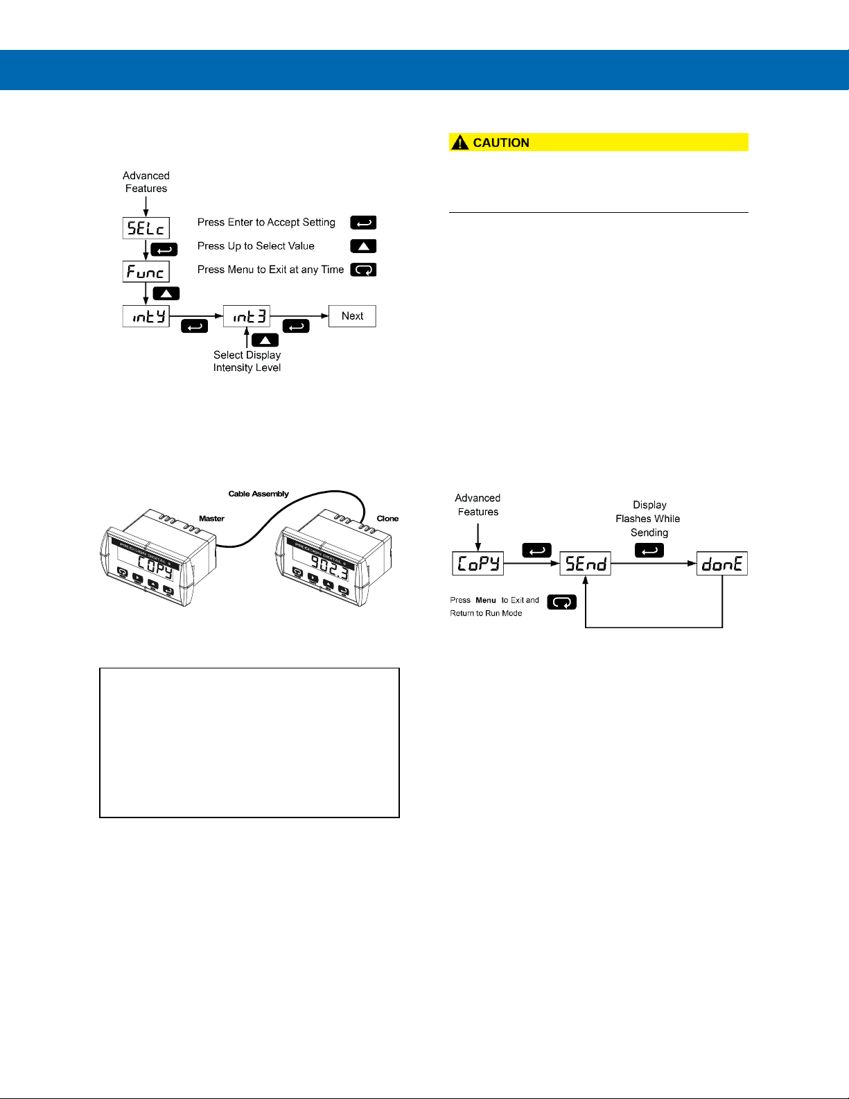
Trident Series PD765 Process & Temperature Meters
Instruction Manual
34
Display Intensity (inty)
The Display Intensity function allows the selection of
eight levels of intensity for various lighting conditions.
Meter Copy Function (Copy)
The Copy function is used to copy (or clone) all the
settings from one meter to other meters requiring
exactly the same setup and programming (i.e. type of
input, scaling, decimal point, filter, bypass, etc.).
Figure 39. Meter Copy Connection
Copy Function Requirements
To successfully copy settings from one meter to
another, both meters must have:
1. Same software version
2. Same baud rate setting
3. PDC protocol selected
See Determining Software Version, page 43
for instructions.
Meter Cloning Instructions
• Do not connect the two meters to the same
4-20 mA loop while cloning. Internal calibration
may be affected.
1. Connect the two meters using cable assembly
PDA7420 or equivalent (e.g. Digi-Key P/N
H1663-07-ND). Cable should not exceed
7' (2.1 m).
2. Power up both meters. Leave Clone meter in
Run Mode.
3. Enter the Advanced Features Menu of the
Master meter, see Advanced Features Menu,
page 31.
4. Scroll to Copy function using Up arrow button
then press Enter/Ack.
5. The meter displays the message Send. Press
Enter/Ack, the display flashes while sending
data. The message done is displayed when
copying is completed.
6. The Clone meter displays the memory address
being programmed then the message done
when copying is completed. The meter
initializes and returns to Run Mode using the
same settings as the Master.
7. If meter to be cloned does not respond to the
data being sent, refer to Copy Function
Requirements above.
Page 35
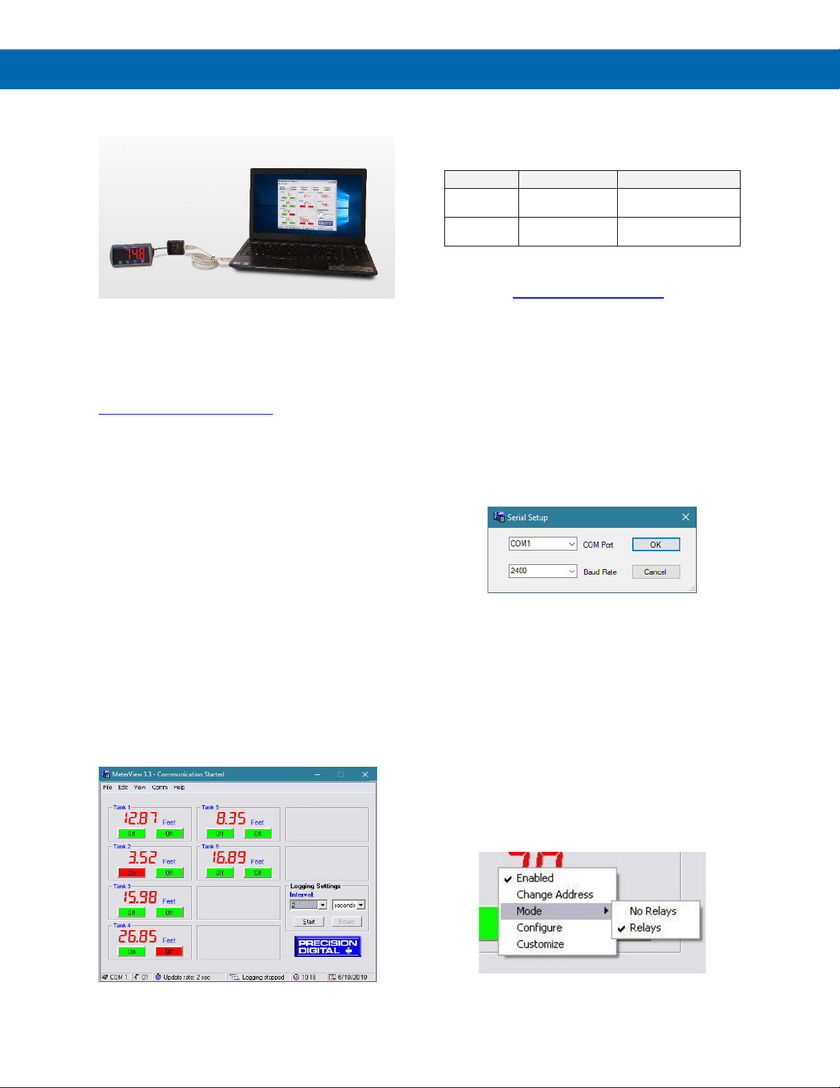
Trident Series PD765 Process & Temperature Meters
Instruction Manual
35
Meterview
Software
Note: Trident meter is not powered from USB connection
and requires external power to be programmed.
The easiest and quickest way to program your Trident
meter is to use the FREE MeterView software. We will
even send you a PDA8006 USB adapter, normally
sold for $39.00, at no cost if you register your meter at
http://www.predig.com/free8006 (limit one per cus-
tomer). You can program the Trident meter you just
bought with the front panel buttons and have the
PDA8006 on hand for programming future meters.
Remote Programming
MeterView software allows all setup parameters to be
programmed remotely from a PC and saved to a file
for reporting or programming other meters.
Data Acquisition
MeterView software provides a convenient way to collect the data generated by the Trident Model PD765
serial output. The user can select the logging time interval. Data can be written to a file, which can then be
imported into a spreadsheet or other application.
Monitoring
Meterview software can be used to monitor up to 100
Trident meters on a PC. The user can set a custom
meter identification, such as Tank 1 to display on the
screen as well as engineering units, such as feet. The
screen shot below shows MeterView software monitoring level in six storage tanks:
Monitoring System Parts
The following table illustrates the parts needed to
monitor 10 Trident meters:
Quantity
Model
Description
10
PDA7422
Trident RS-485
Serial Adapter
1
PDA8485-I
USB to RS-485
Isolated Converter
MeterView Installation
1. Go to www.predig.com/meterview
2. Read instructions & copy serial # of desired
MeterView version
3. Download Installation file to computer
4. Double-click installation file to open it
5. Double-click Setup.exe to begin installation
6. Follow on-screen instructions
Running MeterView the First Time
The first time MeterView is run it is necessary to set
up the serial communication settings of the program.
Select the communication port and the baud rate of
the meter(s) connected.
Note: The selected baud rate in MeterView and the meter(s)
baud rate must be the same. Otherwise a communication error will occur.
Enable Meter and Select Meter
Address
The actual meter address is set up at the meter using
the front panel buttons. The location where a meter is
displayed is selected on MeterView Main window.
To enable or select a meter with a different serial
address:
1. Right-click on the screen location of meter.
2. Click on Enabled, if meter is not yet enabled.
3. Click on Change Address.
4. Select meter address to display in this location.
Page 36
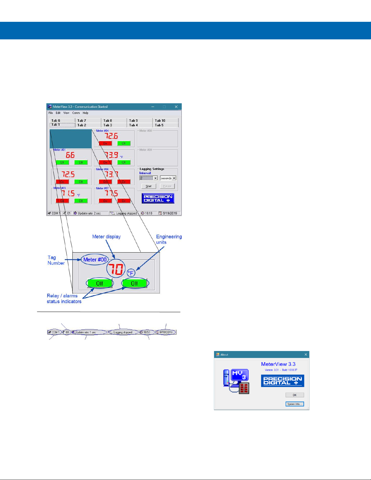
Trident Series PD765 Process & Temperature Meters
Instruction Manual
36
MeterView Main Window
The main MeterView window shows the present
reading(s), relays/alarm status, tag number(s)
and selected engineering units, along with other
information for each meter. The graphic below
indicates the different parts of the main MeterView
window.
Main Window Menus
The MeterView main window contains the following
menus:
• File menu
• Edit menu
• View menu
• Comm Menu
• Help Menu
File Menu
The following options are available from this menu:
1. Exit to close the MeterView program.
Edit Menu
The following options are available from this menu:
1. Serial Settings to edit the serial
communication settings.
2. Number of Meters to automatically populate
the Main Window with a single meter, 10
meters, or 100 meters.
View Menu
The following options are available from this menu:
1. Event Log to view the MeterView event log
window where all internal program events and
errors are logged.
2. Show Relay Alerts select whether or not
MeterView should alert the user of a change
in the relay status (ON → OFF or vice versa)
with a pop-up message.
Comm Menu
The following options are available from this menu:
1. Stop to halt the automatic meter scanning.
This allows quicker access to menu items,
functions, and windows.
2. Start to resume the automatic meter
scanning.
Help Menu
The following options are available from this menu:
1. Online Resources links to Predig.com for
help and product documentation.
2. About Meterview 3.3 for version number and
build information.
Address being
scanned
Logging
System date
COM port
used
Update/scan
System time
Page 37
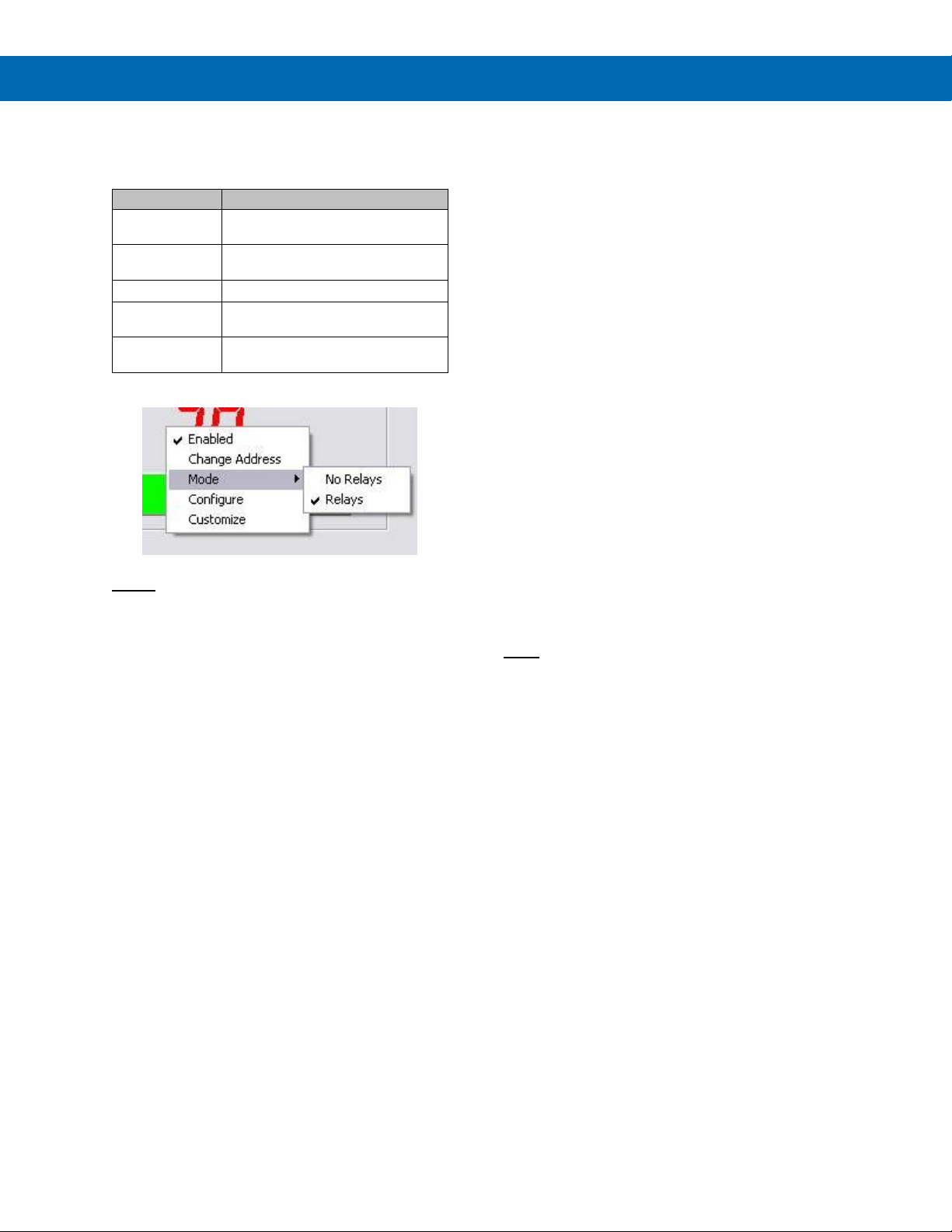
Trident Series PD765 Process & Temperature Meters
Instruction Manual
37
Right Click Menu
By right clicking on a meter on the screen a menu will
appear with the following options:
Menu Item
Function/Submenus
Enabled
Enable or disable a meter on the
screen
Change Address
Change a meter’s serial address in
MeterView
Mode
Show relays
Configure
Access the configuration window for a
meter
Customize
Customize how a meter looks on the
screen
Notes:
• Accessing menus or other windows could disrupt
communication with the meter(s).
• Use left mouse button or tab key on the keyboard
to navigate within a window.
• Parameters not available within a window appear
grayed-out.
• An arrow next to a box indicates a drop-down
menu. Click on arrow to display the drop-down
menu.
Configuration Window
Click on Configure in the right click menu to open a
meter’s configuration window. The following settings
can be programmed from this window:
1. Input type (4-20 mA, 0-10 V, RTD, or TC).
2. Decimal point for process inputs (dd.dd).
3. Units (F or C) and sensor type for
temperature inputs.
4. Values for scaling process inputs, values for
scaling analog output, Password, Adjust
(temperature only), Filter, Bypass, Cutoff
(process inputs only), Transmit Delay,
Function type, and Cut-off.
5. Relay settings.
6. After the last change has been made, click
the Write to Meter button or press Enter on
the keyboard to send the new settings to the
meter, or click on Exit to abandon changes.
Before sending the new settings, MeterView
will ask to confirm that the meter’s current
settings should be overwritten. Click Yes to
overwrite the settings, or No to abort the
operation and return to the configuration
window.
The configuration window contains the following
menus:
• File menu
• Tools menu
• Password menu
Note:
• Accessing menus or other windows could disrupt
communication with the other meter(s).
File Menu
The following options are available from the File
menu:
1. Save Configuration to save the present
settings to a file.
2. Load Configuration to load settings from a
file.
3. Export to HTML to save the present settings
to a HTML file.
4. Import from HTML to load settings from a
HTML file.
5. Print Configuration
Tools Menu
The following options are available from the Tools
menu:
1. Load Defaults to load the factory default
settings.
Page 38
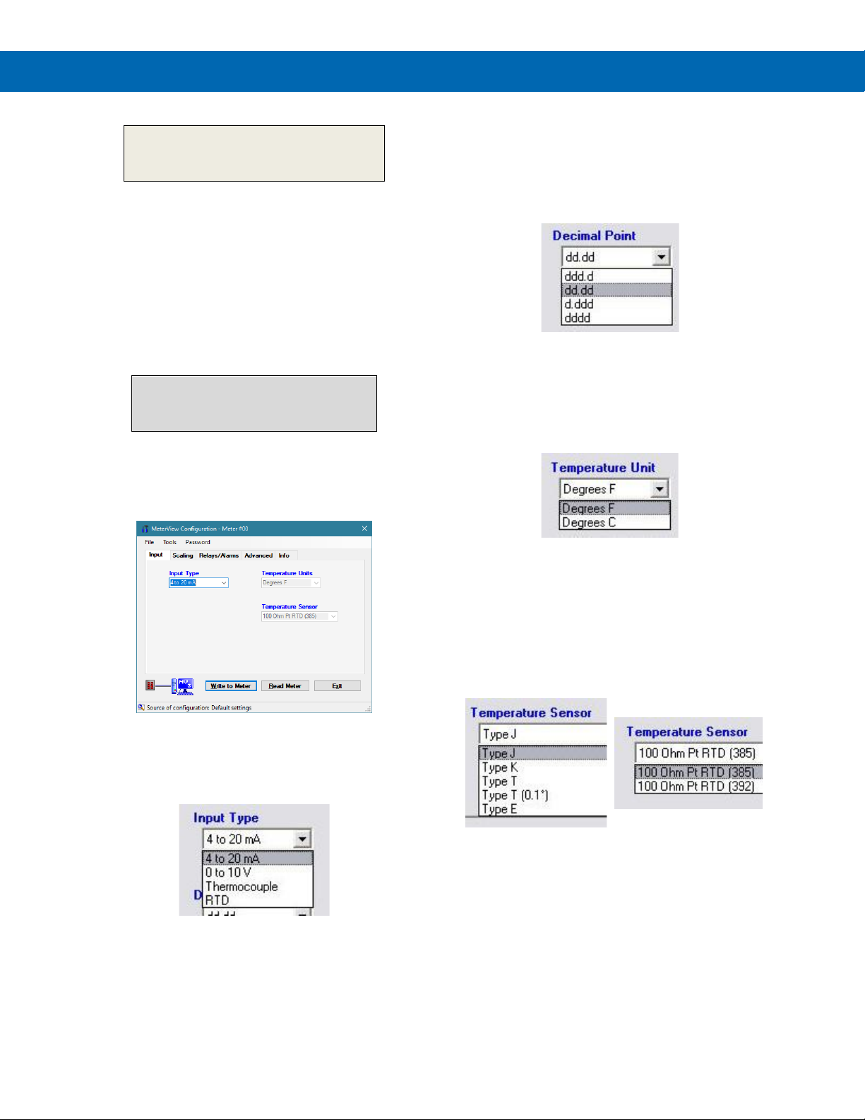
Trident Series PD765 Process & Temperature Meters
Instruction Manual
38
It is recommended to save a configuration
file before changing any setting and before
any calibration operation.
Password Menu
The following options are available from the Password
menu:
1. Lock Meter to lock the meter and prevent
unauthorized changes.
2. Unlock Meter to unlock the meter and allow
changes to be made.
3. Change Password to change the unlock
password of the meter.
The password must be a four-digit
number; “0000” is the unlocked
password setting.
Input Tab
In the configuration window, click on the Input tab to
view the input options.
Set Up Input Type
Click on the arrow next to the 4 to 20 mA box and
then click on the desired input type.
Set Up Decimal Point
Click on the arrow next to the dd.dd box and then
click on the desired decimal point position. Decimal
point selection is available for 4-20 mA and 0-10 V inputs only. The display scale and relay set/reset points
are adjusted according to the decimal point selection.
Set Up Temperature Unit
Click on the arrow next to the Degrees F box and then
click on the desired temperature unit. Temperature
unit selection is available for Thermocouple and RTD
inputs only.
Set Up Temperature Sensor
Click on the arrow next to the Type J box and then
click on the desired temperature sensor. Temperature
sensor selection is available for Thermocouple and
RTD inputs only.
Thermocouple
Sensors
RTD Sensors
Page 39
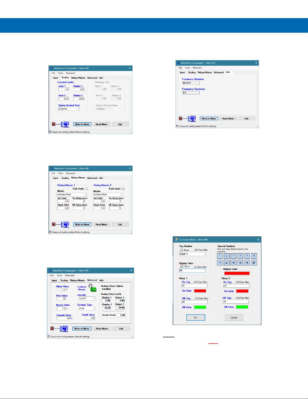
Trident Series PD765 Process & Temperature Meters
Instruction Manual
39
Scaling Tab
In the configuration window, click on the Scaling tab
to view the scaling settings for process inputs (current
and voltage).
Relays/Alarms Tab
In the configuration window, click on the Relays/Alarms tab to view the settings for the re-
lays/alarms.
Advanced Tab
In the configuration window, click on the Advanced
tab to view the advanced settings. Consult the meter
manual for further details.
Info Tab
In the configuration window, click on the info tab to
view the firmware number and version.
Customize Window
Click on Customize in the right click menu to open a
meter’s customize window. The following settings can
be programmed from this window:
1. Tag Number to identify a meter and optionally display it
on the meter. Pre-selected special characters may be
used in this field by simply dragging the desired symbol
into it.
2. Display Units to identify the engineering units of the
value being read and optionally display it on the meter.
Pre-selected special characters may be used in this
field by simply dragging the desired symbol into it.
3. Display Color to change the color of the meter display
on the screen.
4. Relay Tag to change the text label of the Relay Status
indicator(s).
5. Relay Color to change the color of the Relay Status
indicator(s).
Note:
• These settings are NOT saved to the meter.
Page 40
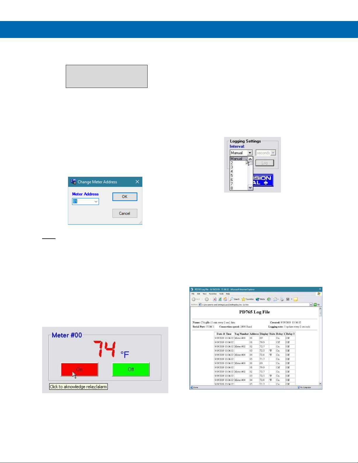
Trident Series PD765 Process & Temperature Meters
Instruction Manual
40
Serial Communication Setup
Addresses for Trident Meter
and MeterView are set to 00 at
the factory.
1. From the main window, click on Edit → Serial
Settings menu to access the Serial
Communication Setup.
2. Select correct communication port used for
Serial Adapter.
3. If timeout error is received, try another serial
port selection or check meter’s address.
To change the serial address of a meter, simply click
on Change Address in the right-click menu. This
setting is on a per-meter basis.
Note:
• Baud rate is set up for 2400 bps at the factory.
Relays/Alarms Status
Each meter enabled in the main MeterView window
can display the current status of its relays/alarms (if
the meter Mode in the right-click menu is set to
Relays) and can allow the user
to remotely acknowledge the relays/alarms
(if applicable). The text labels and colors for the status
indicators may be customized through the Customize
window.
Logging Meter Data to File
1. Click on the arrow next to the Interval box to
select an interval from 2 to 60 or select manual
to log the data only when the Log button is
clicked (Log button is only visible when
manual is selected).
2. Select seconds, minutes, or hours.
3. Click the Start button.
4. Select file location and enter a file name.
Click OK. MeterView will begin logging data
to the file.
Logging may be paused or stopped at any time.
MeterView will indicate logging and paused status
with corresponding message flashing in the main
window status bar. When logging, all other MeterView
functions and windows are not accessible.
Log File Sample
The HTML log file format contains pertinent
information related to the meter and logging
selections. Each log entry includes date and time,
tag number, serial address, display value, units
and relays/alarms status.
Page 41
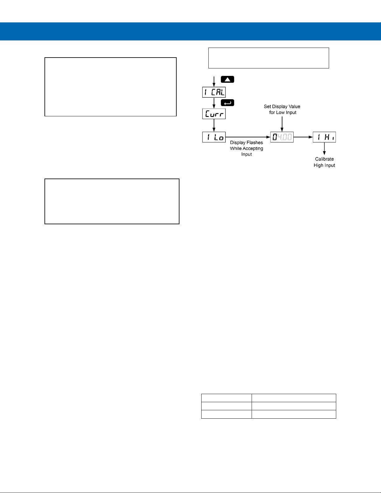
Trident Series PD765 Process & Temperature Meters
Instruction Manual
41
Internal Calibration (ICal)
• There is no need to recalibrate the meter
when first received from the factory.
• The meter is factory calibrated prior to
shipment, for all input types, in milliamps,
volts, and degrees respectively. The
calibration equipment is certified to NIST
standards.
The internal calibration allows the user to scale the
meter without applying a signal. This menu is not
available if the meter is set up for TC or RTD inputs.
The use of calibrated signal sources is necessary to
perform the internal calibration of the meter.
Check calibration of the meter at least every
12 months. Each input type must be recalibrated
separately, if meter will be used with all input types.
Notes:
• If meter is in operation and it is intended to accept
only one input type (e.g. 4-20 mA),
recalibration of other inputs is not necessary.
• Allow the meter to warm up for at least 30 minutes
before performing the internal calibration
procedure.
The Internal calibration menu is part of the Advanced
Features Menu.
1.
2. Press the Right arrow and Menu button
simultaneously or hold the Menu button for
approximately 3 seconds to access the Advanced
Features Menu of the meter.
3. Press the Up arrow button to scroll to the Internal
calibration menu and press Enter/Ack.
4. The meter displays either current (Curr) or
voltage (volt), according to the meter input
setup. Press Enter/Ack to start the calibration
process.
Example for current input internal calibration:
5. The meter displays Low input current (I lo).
Apply the low input signal and press Enter/Ack.
The display flashes for a moment while meter is
accepting the low input.
6. After the display stops flashing, a number is
displayed with the leftmost digit brighter than the
rest. The bright digit is the active digit that can be
changed by pressing the Up arrow button. Press
the Right arrow button to move to the next digit.
7. Set the display value to correspond to the input
signal being calibrated.
8. The display moves to the high input calibration
(I Hi). Apply the high input signal and press
Enter/Ack.
9. Set the display for the high input calibration in the
same way as it was set for the low input
calibration.
For instructions on how to program numeric
values see Setting Numeric Values, page 22.
The graphic above shows the calibration of the
current input. The voltage input is calibrated in a
similar way.
Tips:
• Low and high input signals can be any valid
values within the range of the meter.
• Observe minimum input span requirements
between input 1 and input 2.
• Low input must be less than high input
signal.
Error Message (Err)
An error message indicates that the calibration or
scaling process was not successful.
After the error message is displayed, the meter reverts to input 1, allowing the appropriate input signals
to be applied.
The error message might be caused by any of the
following conditions:
1. Input signal is not connected to the proper
terminals, or it is connected backwards.
2. Wrong signal selection in Setup menu.
3. Minimum input span requirements not
maintained.
Minimum Input Span
The minimum input span is the minimum difference
between input 1 and input 2 signals required to complete
the calibration or scaling of the meter.
Input range
Input 1 & input 2 span
4-20 mA
0.40 mA
10 VDC
0.20 VDC
Page 42
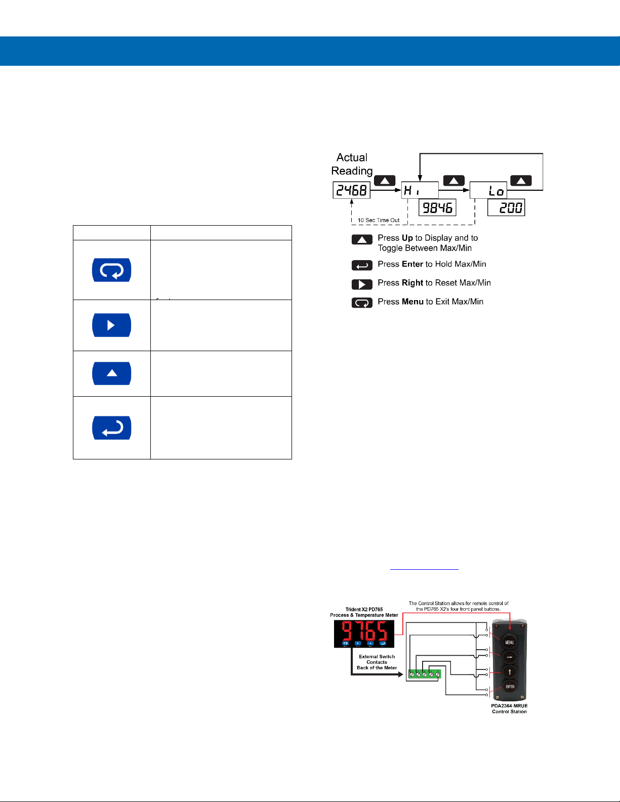
Trident Series PD765 Process & Temperature Meters
Instruction Manual
42
Operation
For process inputs, the meter is capable of accepting
positive and negative signals and displaying these
signals in engineering units from -1999 to 9999 (e.g.
a signal from -10 to +10 VDC could be displayed
as -10.00 to 10.00).
The temperature inputs are displayed according to the
input type and temperature units (F or C) selected.
RTD and Type T thermocouple inputs can be
displayed with either 1 or 0.1 resolution.
Front Panel Buttons Operation
Button Symbol
Description
Press to enter or exit
Programming Mode, view
settings, or exit Max/Min
readings
Hold to enter Advanced
Press to reset Max/Min
readings
Press to display Max/Min
readings alternately
Press to display Max/Min
reading indefinitely while
displaying Max/Min
Press ACK to acknowledge
relays
Maximum/Minimum Readings
The main function of the front panel buttons during
operation is to display the maximum and minimum
readings reached by the process or temperature
inputs.
1. Press Up arrow/Max button to display maximum
reading since the last reset/power-up.
2. Press Up arrow/Max again to display the
minimum reading since the last reset/power-up.
3. Press Enter/Ack to hold Max/Min display
reading, the meter will continue to track new
Max/Min readings.
4. If Enter/Ack is not pressed, the Max/Min display
reading will time out after ten seconds and the
meter will return to display the actual reading.
5. Press Right arrow/Reset button to reset Max/Min
while reading is being displayed. Max/Min display
readings are reset to actual
reading.
Remote Operation of Trident X2
Front Panel Buttons
The Trident PD765 X2's four programming and operations buttons can be remotely controlled for performing such remote actions as resetting relays, viewing
and resetting max / min readings and programming
the meter. The PDA2364-MRUE 4-button control station accessory as shown in the diagram below is a
convenient device for operating the buttons remotely.
Page 43
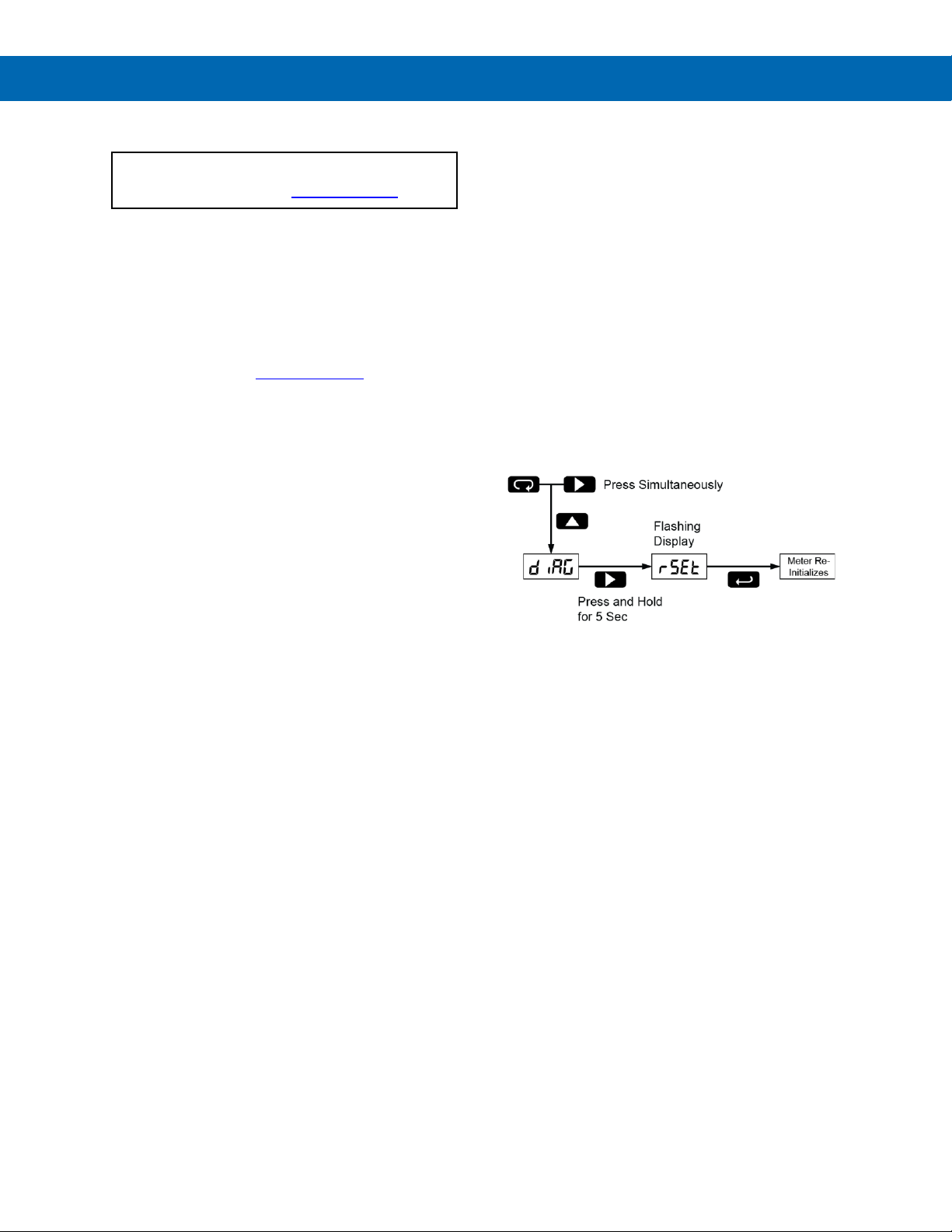
Trident Series PD765 Process & Temperature Meters
Instruction Manual
43
Troubleshooting
For an Interactive Virtual
Meter Demo visit predig.com/tvm
Due to the many features and functions of the meter,
it’s possible that the setup of the meter does not
agree with what an operator expects to see. If the
meter is not working as expected, refer to the
Diagnostics menu and consult the recommendations
described below.
It may also be helpful to program the meter using
MeterView software. A free USB adapter can be sent
to you if you register your meter.
Diagnostics Menu (diag)
The Diagnostics menu is located in the Advanced
Features Menu, to access Diagnostics menu see
Advanced Features Menu, page 31.
It provides an easy way to view the programmed
parameter settings for troubleshooting purposes.
Press the Enter/Ack button to view the settings and
the Menu button to exit at any time.
For a description of the diagnostics messages see
Advanced Features Menu & Display Messages,
page 31.
Determining Software Version
To determine the software version of a meter:
1. Go to the Diagnostics menu (diAG) and
press Enter/Ack button.
2. Press Up arrow/Max button and scroll to
Information menu (Info).
3. Press Enter/Ack to access the software
number (SFT), version (UER). Write down the
information as it is displayed. Continue
pressing Enter/Ack until all the information
is displayed.
Reset Meter to Factory Defaults
When the parameters have been changed in a way
that is difficult to determine what’s happening, it might
be better to start the setup process from the factory
defaults.
Instructions to load factory defaults:
1. Enter the Advanced Features Menu. See
Advanced Features Menu, page 31.
2. Press Up arrow to go to Diagnostics menu
3. Press and hold Right arrow/Reset for five
seconds, press Enter/Ack when display
flashes reset.
Note: If Enter/Ack is not pressed within
three seconds, display returns to Diagnostics
menu.
4. The meter goes through an initialization
sequence (same as on power-up) and loads
the factory default settings.
Page 44

Trident Series PD765 Process & Temperature Meters
Instruction Manual
44
Factory Defaults & User Settings
The following table shows the factory setting for most
of the programmable parameters on the meter. Next
to the factory setting, the user may record the new
setting for the particular application. MeterView
software allows the saving of all meter parameters to
a file for restoring meter settings, reporting, and
copying settings to other meters.
Model: ______________ S/N: _______________
Date: _______________
Parameter
Display
Default
Setting
User
Setting
Input type
inpt
4-20 mA
Decimal point
dd.dd
2 places
Programming
prog
Input 1
InP1
4.00 mA
Display 1
Dis1
4.00 Input 2
InP2
20.00 mA
Display 2
Dis2
20.00
Relay 1
Rly1
Action 1
Act1
Automatic
Set 1
Set1
7.00 Reset 1
RSt1
6.00 Relay 2
Rly2
Action 2
Act2
Automatic
Set 2
Set2
10.00
Reset 2
RSt2
9.00
Fail-safe
flsf
Fail-safe 1
Fls1
Off Fail-safe 2
Fls2
Off Time delay
dlay
On delay 1
On1
0 sec
Off delay 1
Off1
0 sec
On delay 2
On2
0 sec
Off delay 2
Off2
0 sec
Parameter
Display
Default
Setting
User
Setting
Break 1
Brk1
Off Break 2
Brk2
Off
Password
pass
0000
(unlocked)
Advanced
Features
N/A
Adjust
Adj
0.0 (temp
only) Filter
fltr
10 Bypass
byps
0.2 Serial settings
serl
Protocol
pdC
PDC
protocol
Address
addr
00
Baud rate
baud
2400
Trans delay
trde
10 ms
Function
Func
Linear
Cutoff value
CutF
0.00
(disabled)
Output option
out/Aou
t
Factory set
only
Display
intensity
inty
Level 8
Modbus
defaults
N/A
Address
addr
247
Parity
prty
Even
Byte-to-byte
timeout*
tbyt
0.01 sec
*Note:
The byte-to-byte timeout setting might be updated
automatically depending on the baud rate selected
and the previous timeout setting. The minimum
timeout allowed is saved to memory if a lower value is
entered (e.g. If user enters 0.00 with a baud rate of
300, 0.06 is saved)
Page 45
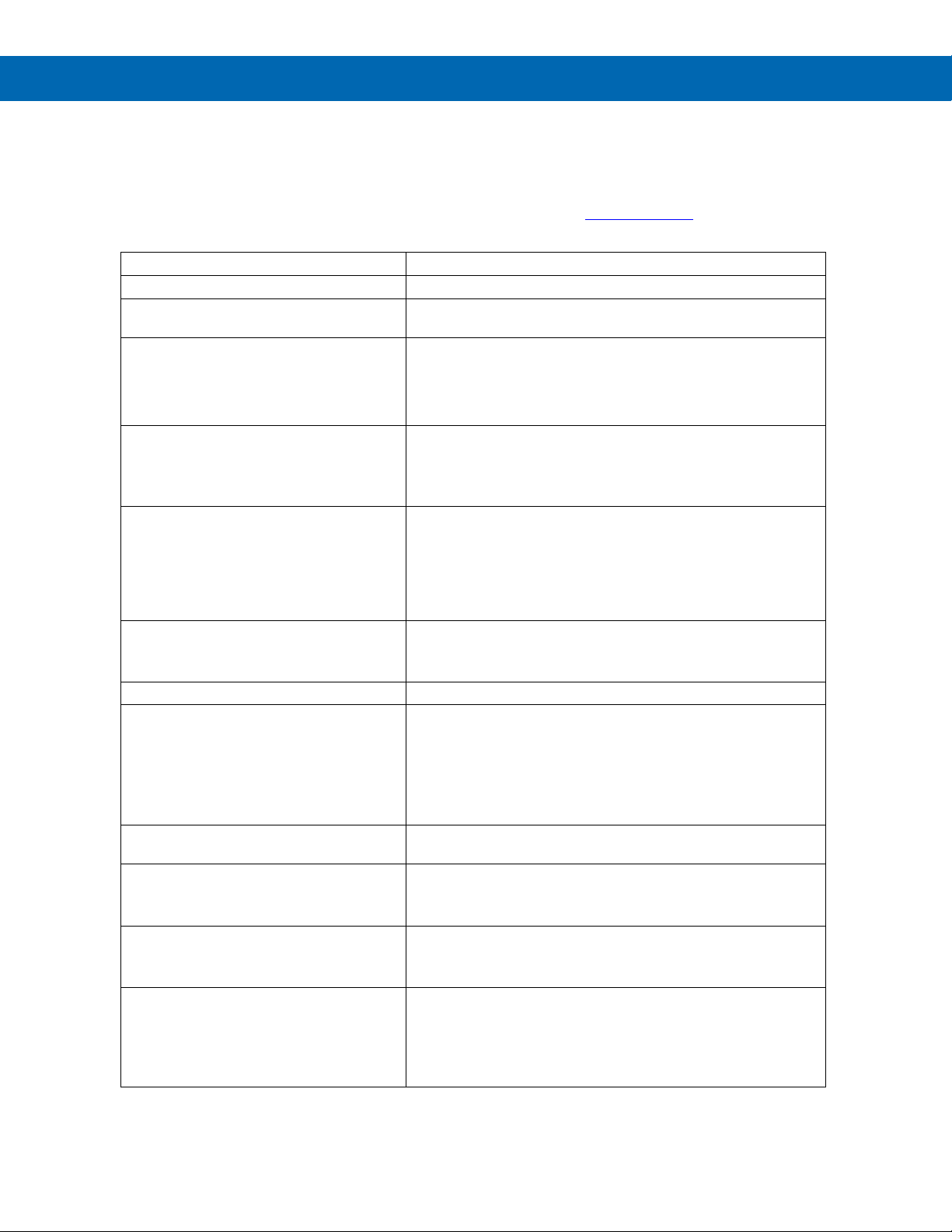
Trident Series PD765 Process & Temperature Meters
Instruction Manual
45
Troubleshooting Tips
This meter is a highly sophisticated instrument with an extensive list of features and capabilities. If the front panel buttons are used to program the meter, it may be a difficult task to keep everything straight. That is why we strongly recommend the use of the MeterView software for all programming activities. A free USB adapter is available for programming with MeterView software if you register your meter.
Symptom
Check/Action
No display at all
Check power at power connector
Not able to change setup or programming,
LoCd is displayed
Meter is locked, enter correct four-digit password to unlock
Meter does not respond to input change
If a Low-Flow Cutoff Value has been programmed, the meter will
display zero below that point, regardless of the input – which can
appear like the meter is not responding to an input change.
Check to make sure the problem is not being caused by an
undesired low-flow cutoff value.
Meter displays error message during
calibration (err)
Check:
1. Signal connections
2. Input selected in Setup menu
3. Minimum input span requirements
Meter displays
• open
• 9999
• -1999
• Displays negative number, not
responding to RTD.
Check:
1. Input selected in Setup menu
2. TC/RTD Switch position
3. Corresponding signal at Signal connector
Display alternates between
1. Hi and a number
2. Lo and a number
Press Menu to exit Max/Min
display readings.
Display response is too slow
Check filter and bypass values
Inaccurate temperature reading
Check:
1. Temperature units (F or C)
2. TC type or RTD curve selected
3. Offset adjustment
4. TC wire used
5. Calibration
If the display locks up or the meter does
not respond at all
Cycle the power to restart the microprocessor.
Relay operation is reversed
Check:
1. Fail-safe in Setup menu
2. Wiring of relay contacts
Relay and status LED do not
respond to signal
Check:
1. Relay action in Setup menu
2. Set and reset points
Meter not communicating with MeterView
or other programs
Check:
1. Serial adapter and cable
2. Serial protocol selected
3. Meter address and baud rate
4. MeterView address and baud rate
Page 46
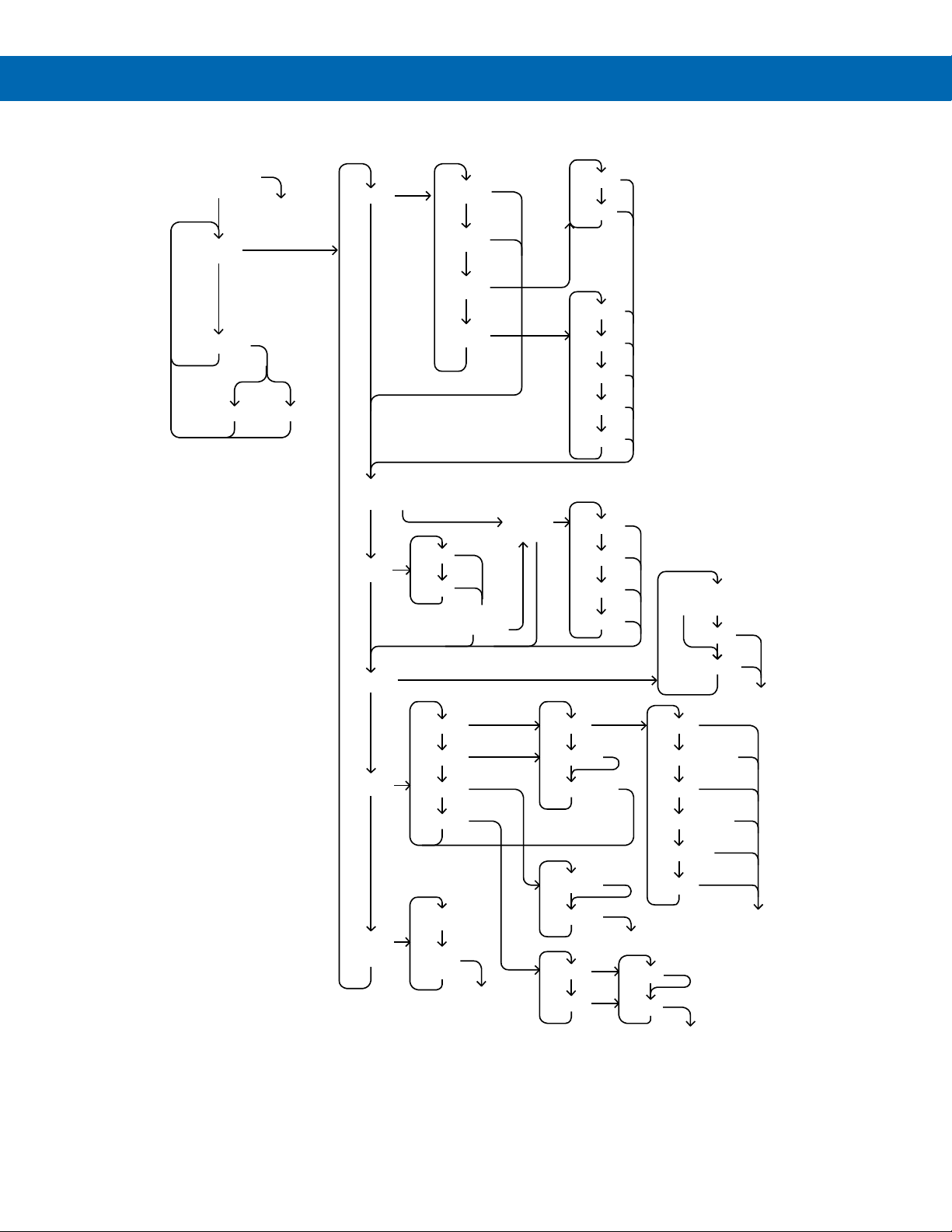
Trident Series PD765 Process & Temperature Meters
Instruction Manual
46
Quick Interface Reference Guide
Run Mode
Setup
Password
Display
Max/Min
Input
4-20 mA
0-10 V
RTD
TC
Decimal
Point
dddd
d . ddd
dd . dd
ddd . d
A385
A392
Type J
Type K
Type T
Type T.0
Type E
F
C
F or C
To Program
Locked Unlocked
TC or RTD?
Yes No
Relays
Relay 1
Relay 2
Failsafe
Delays
Action
Set point
Reset point
Auto
Auto & Manual
Latch
Latch w/Clear
Pump Alt
Off
To
Set point
Failsafe 1
Failsafe 2
To Delays
Delay 1
Delay 2
On
Off
Analog
output
Scale
Sensor
break
To Password
RTD or Type T
No Yes
Calibrate
Scale
TC or RTD?
Yes No
Program
To Relays
Page 47
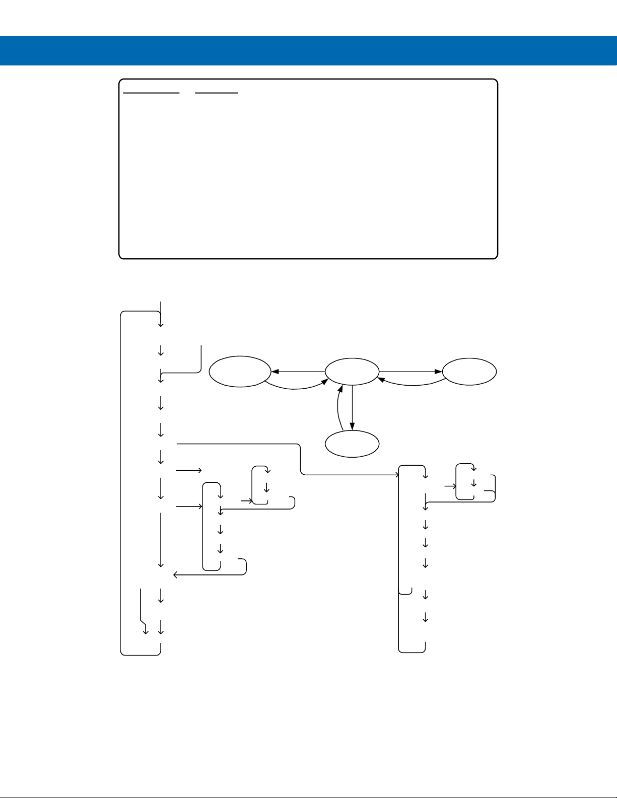
Trident Series PD765 Process & Temperature Meters
Instruction Manual
47
Right Arrow & Menu
(or hold Menu for 3 sec)
Pushbutton Function
Menu Go to Programming Mode or leave Programming, Advanced
Features, and Max/Min Modes.
Right Arrow Move to next digit.
Up Arrow Move to next selection or increment digit.
Enter/Ack Accept selection/value and move to next selection.
Right Arrow & Menu simultaneously enters Advanced Features
Max/Min Mode
While in Run Mode, pressing Up Arrow will initiate Max/Min Mode. Up Arrow
toggles between Max & Min displays, and Right Arrow resets the Max/Min to the
current value. Press Menu or wait 10 seconds to return to Run Mode. Pressing
Enter/Ack will disable the 10 second timeout and continuously display Max or Min.
Press Right arrow and Menu
to access Advanced Features
Menu
When the meter is locked, Adjust,
Filter and Bypass can only display
their settings, and the Copy and
ICAL functions are not available.
Adjust
Filter
Bypass
Serial
Copy Send
TC or RTD?
Yes No
TC or RTD?
Yes No
Initial
Calibrate
Diagnostics
Select
Function
Cutoff
Output
Linear
Sq. Root
Address
TX Delay
Baud
Protocol
Parity
Modbus
PDC
Byte-to-byte
timeout
Modbus?
No Yes
Intensity
Program
Run
Max &
Min
Advanced
Features
Up Arrow
Menu
Menu
Menu
Menu
Operational Modes
Page 48

Trident Series PD765 Process & Temperature Meters
Instruction Manual
PRECISION DIGITAL CORPORATION
233 South Street • Hopkinton MA 01748 USA
Tel (800) 343-1001 • Fax (508) 655-8990
www.predig.com
LIM765_U
SFT031 & SFT077 Ver 3.300 & up
02/22
Contact Precision Digital
Technical Support
Call: (800) 610-5239 or (508) 655-7300
Fax: (508) 655-8990
Email: [email protected]
Sales Support
Call: (800) 343-1001 or (508) 655-7300
Fax: (508) 655-8990
Email: [email protected]
Place Orders
Email: [email protected]
For the latest version of this manual please visit
www.predig.com
 Loading...