

Page 1
PRECISION DIGITAL CORPORATION
19 Strathmore Road • Natick MA 01760 USA
Tel (800) 343-1001 • Fax (508) 655-8990
www.predig.com
DIGITAL METERS
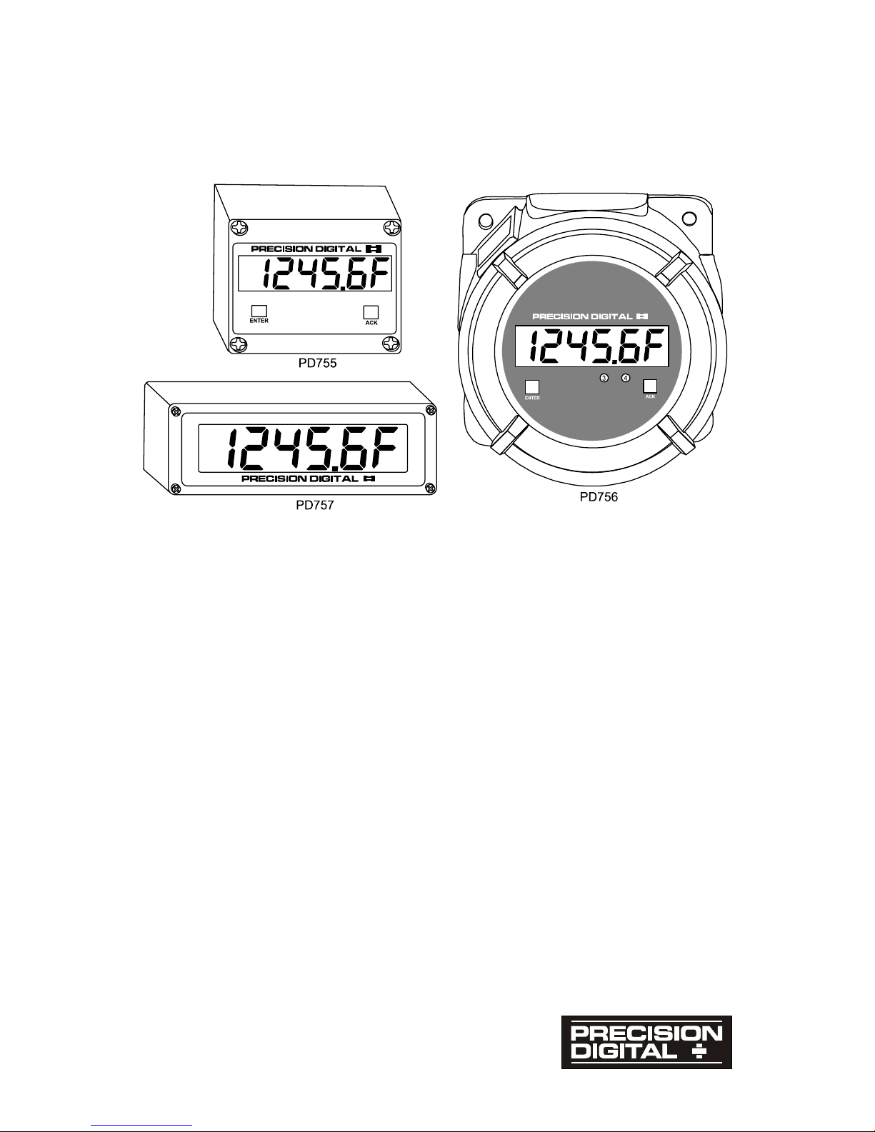
Large Display Temperature Meters
Instruction Manual
• Handles Thermocouple and RTD Inputs with Simplicity
• J, K, T, E, R and S Thermocouples
• 100 Ω Platinum RTDs (0.00385 or 0.00392 curve)
• Large Display Readouts: 2.3", 1.0" and 0.8" High
• Display Resolution
Thermocouples: 1°, Type T T/C Displayed to 1° or 0.1°
RTDs Resolution: 1° or 0.1°, Field Selectable
• Displays °F or °C, Field Selectable
• No Calibration Necessary – Factory Calibrated
• Maximum/Minimum Temperature Display
• Input Offset Adjustment
• NEMA 4X and Explosion-Proof Enclosures
• 115 or 230 VAC Power, Field Selectable
• 24 VDC Powered Models, Optional
• 24 VDC Isolated Power Supply Standard on AC Models
• 4 Visual Alarm Points with Front Panel LED Status Indication
• 2 or 4 Relays and/or 4-20 mA Output Options
Page 2

Large Display Temperature Meters Instruction Manual
2
Visit our website
http://www.predig.com
Page 3

Large Display Temperature Meters Instruction Manual
3
Table of Contents
INTRODUCTION ----------------------------------------------------------------------- 7
Ordering Information ------------------------------------------------------------------------7
Model PD755 --------------------------------------------------------------------------------7
Model PD756 --------------------------------------------------------------------------------7
Model PD757 --------------------------------------------------------------------------------8
Accessories ----------------------------------------------------------------------------------8
Safety Notice ----------------------------------------------------------------------------------- 9
Specifications-------------------------------------------------------------------------------- 10
Basic Temperature Meter -------------------------------------------------------------- 10
Options -------------------------------------------------------------------------------------- 12
Display Functions and Messages----------------------------------------------------- 14
SETUP AND PROGRAMMING -------------------------------------------------- 15
Overview--------------------------------------------------------------------------------------- 15
Disassembling the Meter----------------------------------------------------------------- 16
Disassembling the PD755 -------------------------------------------------------------- 16
Disassembling the PD756 -------------------------------------------------------------- 16
Disassembling the PD757 -------------------------------------------------------------- 17
Reassembling the Meter ----------------------------------------------------------------- 18
Reassembling the PD755 -------------------------------------------------------------- 18
Reassembling the PD756 -------------------------------------------------------------- 18
Reassembling the PD757 -------------------------------------------------------------- 18
Jumper Configuration--------------------------------------------------------------------- 19
Input Selection and Lockout Jumpers (Main PCB)------------------------------- 19
Relay Acknowledge Enable (Display PCB) ---------------------------------------- 19
Fail-Safe Operation of Relays (Options PCB)------------------------------------- 19
Power Selection----------------------------------------------------------------------------- 20
Overview------------------------------------------------------------------------------------ 20
Changing from 115 to 230 VAC Power --------------------------------------------- 20
Labeling Meter for 115 VAC, 230 VAC or 24 VDC------------------------------- 21
Connections---------------------------------------------------------------------------------- 21
Overview------------------------------------------------------------------------------------ 21
Wiring Instructions------------------------------------------------------------------------ 22
Power Connections ---------------------------------------------------------------------- 23
Signal Connections----------------------------------------------------------------------- 24
Enter, Acknowledgement, and Hold Connections -------------------------------- 26
Optional Relays & 4-20 mA Output Terminals ------------------------------------ 27
Isolated 4-20 mA Output Transmitter Connections ------------------------------ 28
Page 4

Large Display Temperature Meters Instruction Manual
4
Programming -------------------------------------------------------------------------------- 29
Overview------------------------------------------------------------------------------------ 29
Select Type of Input Signal T/C or RTD----------------------------------------- 29
ENTER Button Functionality ------------------------------------------------------- 30
ACK Button Functionality ----------------------------------------------------------- 30
Magnetic Reed Switch Functionality --------------------------------------------- 30
General Programming Description --------------------------------------------------- 31
Five Basic Digit/Display-Setting Instructions ----------------------------------- 31
Programming the Basic Meter--------------------------------------------------------- 32
Selecting Type of T/C or RTD (TYPE) -------------------------------------------- 33
Select °F or °C (f or C) ------------------------------------------------------------ 33
Alarm Setup and Set Points Programming----------------------------------------- 34
Overview -------------------------------------------------------------------------------- 34
Set Relays for Manual or Automatic Reset ------------------------------------- 34
Set Relays for Fail-Safe Operation ----------------------------------------------- 34
Setup for Latching or Non-Latching Relays (SetuP) ------------------------- 35
Alarm Set and Reset Points Programming ------------------------------------- 36
Programming Alarm Points Using Set Points (setpts) Menu ------------- 37
Alarm Set and Reset Programming Confirmation ---------------------------- 37
Isolated 4-20 mA Output Transmitter Option -------------------------------------- 38
4-20 mA Output Programming (output) ---------------------------------------- 38
4-20 mA Output Programming Confirmation ----------------------------------- 38
Input Offset Adjustment (OFFSEt) ---------------------------------------------------- 39
Lockout Jumper --------------------------------------------------------------------------- 39
OPERATION -------------------------------------------------------------------------- 40
Overview--------------------------------------------------------------------------------------- 40
Basic Meter Operation -------------------------------------------------------------------- 41
Overview------------------------------------------------------------------------------------ 41
Maximum/Minimum Temperature Display------------------------------------------ 41
Relays Operation --------------------------------------------------------------------------- 42
Overview------------------------------------------------------------------------------------ 42
Relays Auto Initialization---------------------------------------------------------------- 42
Fail-Safe Operation ---------------------------------------------------------------------- 42
Front Panel LEDs------------------------------------------------------------------------- 43
Acknowledging Relays ------------------------------------------------------------------ 45
Switching Inductive Loads-------------------------------------------------------------- 46
4-20 mA Output Operation ------------------------------------------------------------- 46
RECALIBRATION (CALIB) -------------------------------------------------------- 47
Calibration Error (error) --------------------------------------------------------------- 47
Recommended Calibration Points ---------------------------------------------------- 48
Minimum Input Span--------------------------------------------------------------------- 48
Calibration Verification ------------------------------------------------------------------- 48
Page 5

Large Display Temperature Meters Instruction Manual
5
INSTALLATION ---------------------------------------------------------------------- 49
Wall Mounting Instructions ------------------------------------------------------------- 49
PD755 Mounting -------------------------------------------------------------------------- 49
PD756 Mounting -------------------------------------------------------------------------- 49
PD757 Mounting -------------------------------------------------------------------------- 49
Panel Mounting Instructions------------------------------------------------------------ 50
PD755 Panel Mounting Instructions ------------------------------------------------- 50
PD757 Panel Mounting Instructions ------------------------------------------------- 51
Pipe Mounting Instructions for PD755 and PD756 ------------------------------ 53
Explosion-Proof Control Stations----------------------------------------------------- 55
OPTION CARD REMOVAL & INSTALLATION ----------------------------- 56
Option Card Installation in PD755 ---------------------------------------------------- 56
Option Card Installation in PD756 ---------------------------------------------------- 58
Option Card Installation in PD757 ---------------------------------------------------- 59
MODEL SENSITIVE ILLUSTRATIONS ---------------------------------------- 60
Removing the Display PCB ------------------------------------------------------------- 60
Locations of Connections and Jumpers-------------------------------------------- 61
Jumper Arrays and Status LEDs ------------------------------------------------------ 63
Front Panel Displays ---------------------------------------------------------------------- 65
Overall Dimensions ------------------------------------------------------------------------ 66
Wall Mounting Dimensions-------------------------------------------------------------- 67
PROGRAMMED PARAMETER SETTINGS ---------------------------------- 69
OTHER PRECISION DIGITAL PRODUCTS---------------------------------- 70
Page 6

Large Display Temperature Meters Instruction Manual
6
List of Figures
Figure 1. Input Power Label ................................................................. 21
Figure 2. Input Power Connections for 756 and 757 .......................... 23
Figure 3. Four-Wire RTD Connections ................................................ 24
Figure 4. Three-Wire RTD Connections............................................... 24
Figure 5. Two-Wire RTD Connections ................................................. 25
Figure 6. Thermocouple Connections................................................. 25
Figure 7. External Control Connections.............................................. 26
Figure 8. Relay and 4-20 mA Output Terminals.................................. 27
Figure 9. Output Loop Powered by Meter ........................................... 28
Figure 10. Output Loop Powered from External Power Supply........... 28
Figure 11. JP1 Input Signal Selection Array. ......................................... 29
Figure 12. Reed Switch Operation.......................................................... 30
Figure 13. AC and DC Loads Protection ................................................ 46
Figure 14. Low Voltage DC Loads Protection ....................................... 46
Figure 15. PD755 Panel Mounting .......................................................... 50
Figure 16. PD757 Panel Mounting .......................................................... 51
Figure 17. PD757 Panel Mounting Cutout Dimensions......................... 51
Figure 18. 755 Pipe Mounting Assembly................................................ 53
Figure 19. 756 Pipe Mounting Assembly................................................ 53
Figure 20. Pipe Mounting Plate............................................................... 54
Figure 21. Explosion-proof Control Station........................................... 55
Figure 22. Removing the PD755 Display PCB ....................................... 56
Figure 23. PD755 Options PCB Standoffs Location.............................. 56
Figure 24. PD755 Options PCB Installation ........................................... 57
Figure 25. PD756 Option PCB Installation ............................................. 58
Figure 26. PD756 Option PCB Installed ................................................. 58
Figure 27. PD757 Option PCB Installation ............................................. 59
Figure 28. Removing the Display PCB on PD755.................................. 60
Figure 29. Removing the Display PCB on PD756.................................. 60
Figure 30. Removing the Display PCB on PD757.................................. 61
Figure 31. PD755 Connectors and Jumper Location ............................ 61
Figure 32. PD756 Connectors and Jumper Location ............................ 62
Figure 33. PD757 Connectors and Jumper Location ............................ 62
Figure 34. PD755 Jumper Arrays and Status LED Identification ......... 63
Figure 35. PD756 Jumper Arrays and Status LED Identification ......... 63
Figure 36. PD757 Jumper Arrays and Status LED Identification ......... 64
Figure 37. PD755 Front Panel Display.................................................... 65
Figure 38. PD756 Front Panel Display.................................................... 65
Figure 39. PD757 Front Panel Display.................................................... 65
Figure 40. PD755 Overall Dimensions.................................................... 66
Figure 41. PD756 Overall Dimensions.................................................... 66
Figure 42. PD757 Overall Dimensions.................................................... 67
Figure 43. PD755 Wall Mounting Dimensions ....................................... 67
Figure 44. PD755 Wall Mounting Screw Installation ............................. 67
Figure 45. PD756 Wall Mounting Dimensions ....................................... 68
Figure 46. PD757 Wall Mounting Dimensions ....................................... 68
Page 7
Large Display Temperature Meters Instruction Manual
7
INTRODUCTION
The Large Display Temperature Meters are housed in rugged, NEMA 4X
or explosion-proof enclosures. These meters handle temperature display
and alarm applications with simplicity, accuracy, and reliability. They
accept the common thermocouples J, K, T, E, R, and S or 100 Ω
platinum RTDs. Options include up to 4 relays for alarms as well as an
isolated 4-20 mA transmitter output. An isolated 24 VDC power supply is
available as standard feature on AC powered models to power the
transmitter output.
Ordering Information
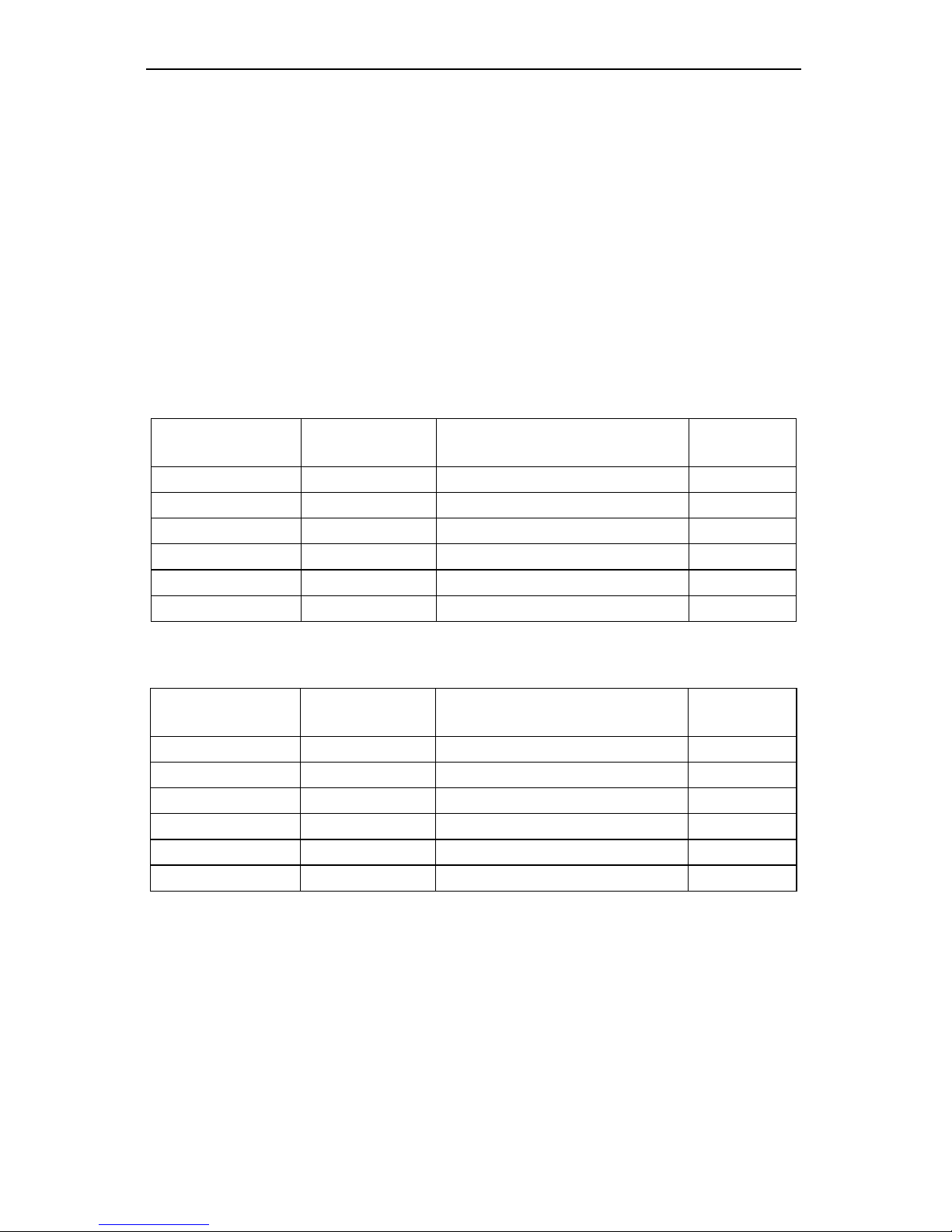
Model PD755
115/230 VAC
MODEL
24 VDC
MODEL
DESCRIPTION Option
Card*
PD755-N PD755-2-N No Options
PD755-44 PD755-2-44 2 Relays PD474
PD755-45 PD755-2-45 4-20 mA Output PD475
PD755-46 PD755-2-46 2 Relays + 4-20 mA Output PD476
PD755-47 PD755-2-47 4 Relays PD477
PD755-48 PD755-2-48 4 Relays + 4-20 mA Output PD478
Model PD756
115/230 VAC
MODEL
24 VDC
MODEL
DESCRIPTION Option
Card*
PD756-N PD756-2-N No Options
PD756-44 PD756-2-44 2 Relays PD474
PD756-45 PD756-2-45 4-20 mA Output PD475
PD756-46 PD756-2-46 2 Relays + 4-20 mA Output PD476
PD756-47 PD756-2-47 4 Relays PD477
PD756-48 PD756-2-48 4 Relays + 4-20 mA Output PD478
*Option Cards (When Ordered Separately)
Page 8
Large Display Temperature Meters Instruction Manual
8
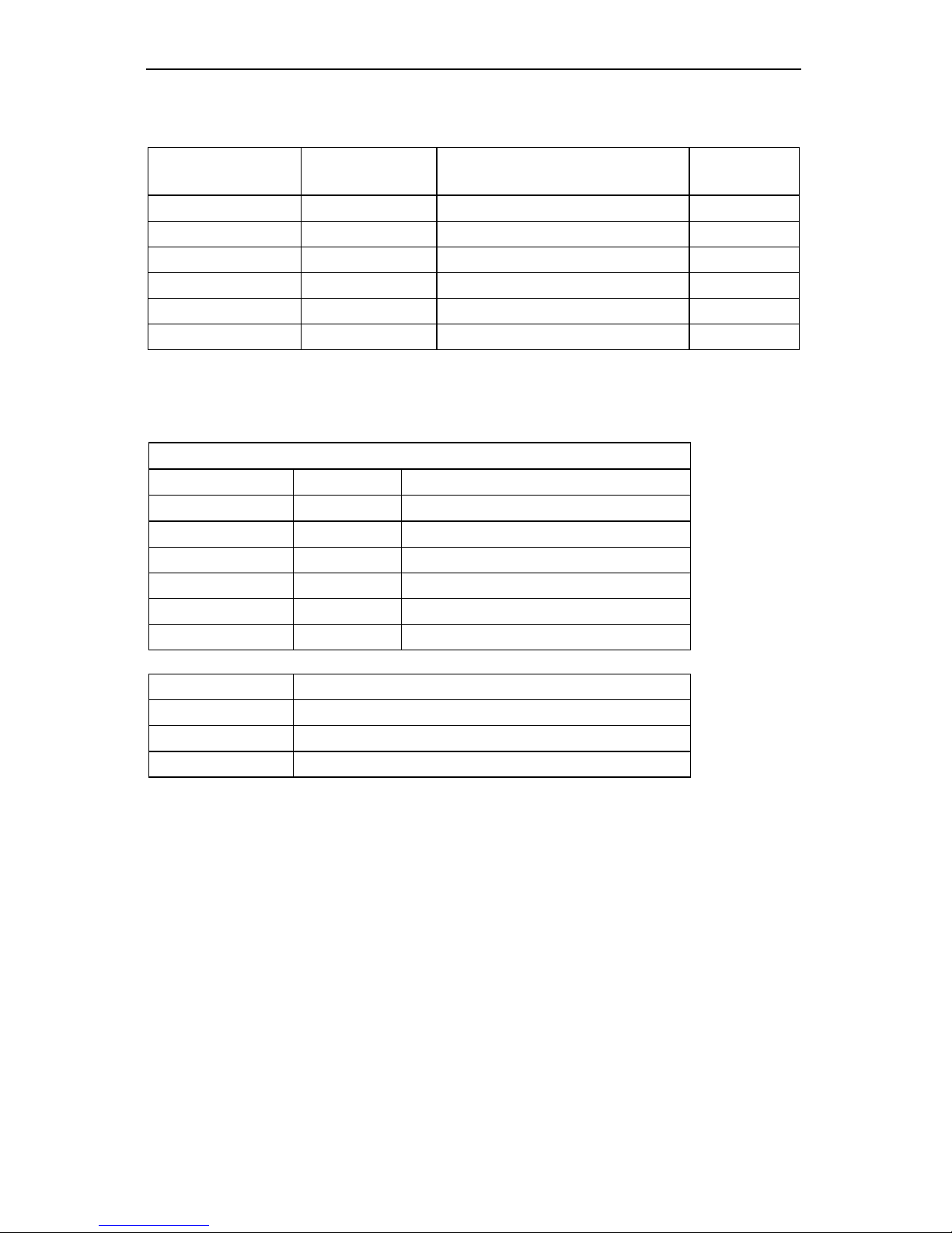
Model PD757
115/230 VAC
MODEL
24 VDC
MODEL
DESCRIPTION Option
Card*
PD757-N PD757-2-N No Options
PD757-34 PD757-2-34 2 Relays PD374
PD757-35 PD757-2-35 4-20 mA Output PD375
PD757-36 PD757-2-36 2 Relays + 4-20 mA Output PD376
PD757-37 PD757-2-37 4 Relays PD377
PD757-38 PD757-2-38 4 Relays + 4-20 mA Output PD378
*Option Cards (When Ordered Separately)
Accessories
Control Stations
Model Switches Labels
PDA2451-E 1 ENTER
PDA2451-A 1 ACK
PDA2451-R 1 RESET
PDA2452-EA 2 ENTER and ACK
PDA2452-ER 2 ENTER and RESET
PDA2453-EAR 3 ENTER, ACK, and RESET
PDA-MAG Magnet Assembly for PD656 & PD756
PDA6504 Panel Mounting Kit for PD757**
PDA6554 Panel Mounting Kit for PD755**
PDA6545 2" Pipe Mounting Kit for PD755 and PD756
** These panel mounting kits are not intended to provide waterproof protection to
the panel.
Page 9
Large Display Temperature Meters Instruction Manual
9
Safety Notice
!
CAUTION: Read complete
instructions prior to installation and
operation of the meter.
WARNING: Risk of electric shock.
!
Observe all safety regulations. Electrical wiring should be performed in
accordance with all applicable national, state, and local codes to
prevent damage to the meter and ensure personnel safety.
!
It is recommended to use this meter in a fail-safe system that
accommodates the possibility of meter failure or power failure.
WARNING
Hazardous voltages exist within enclosure. Installation and service should
be performed only by trained service personnel.
AVERTISSEMENT
Les pièces à l'intérieur du boîtier portent des tensions dangereuses. Seules
des personnes qualifiées et bien entrainées devraient entreprondre
l'ótalonnage et la maintenance.
Disclaimer
The information contained in this document is subject to change without notice.
Precision Digital makes no representations or warranties with respect to the
contents hereof, and specifically disclaims any implied warranties of
merchantability or fitness for a particular purpose.
Page 10

Large Display Temperature Meters Instruction Manual
10
Specifications
Except where noted all specifications apply to operation at +25°C.
Basic Temperature Meter
INPUTS
Field selectable: type J, K, T, E, R, or S thermocouples with 1°
resolution; type T to 0.1°; 100 Ω platinum RTD (0.00385 or
0.00392 curve) to 1° or 0.1° resolution.
DISPLAY
4½ digit, high efficiency red LED, automatic lead zero blanking,
F or C displayed to indicate Fahrenheit or Celsius.
Digit Size:
PD755– 1.0" (25.4 mm) high
PD756– 0.8" (20.3 mm) high
PD757– 2.3" (58.0 mm) high
COLD JUNCTION
REFERENCE
Automatic, fixed, no user calibration needed.
INPUT
IMPEDANCE
Greater than 100 kΩ
LOCKOUT
Jumper JP2, located on Main PCB, restricts modification of set
values.
ACCURACY
Input
Type
Range Accuracy
Type J T/C
–328° to 1382° F
–200° to 750°C
±2°F
±1°C
Type K T/C
–328° to 2498°F
–200° to 1330°C
±2°F
±1°C
Type T T/C
–330.0° to 760.0°F
–200.0° to 404.0°C
±2°F
±1°C
Type E T/C
–328° to 1832°F
–200° to 1000°C
±2°F
±1°C
Type R T/C
32° to 3213°F
0° to 1767°C
±5°F
±3°C
Type S T/C
40° to 3214°F
4° to 1768°C
±6°F
±3°C
100 Ω RTD –328.0° to 1382.0°F
–200.0° to 750.0°C
±0.7°F
±0.4°C
RECALIBRATION
All ranges are calibrated at the factory. Recalibration is
recommended at least every 12 months.
INPUT OFFSET
Programmable to ±100% FS display. This parameter allows the
user to apply an offset value to the input temperature being
displayed.
SENSOR BREAK
DETECTION
Open sensor circuit indicated by display flashing OPEn. All relays
and alarm status LEDs go to alarm state.
MAX/MIN
TEMPERATURE
DISPLAY
The maximum and minimum temperature reached by the process
is stored in memory until cleared (reset) by the user or until power
to the meter is turned off. Max/min values are displayed via the
ENTER button and
HI t, LO t menu functions, respectively.
Page 11

Large Display Temperature Meters Instruction Manual
11
ALARM POINTS
Four, any combination of high or low alarms. Latching or nonlatching.
ALARM POINT
DEADBAND
0-100% of full scale, user selectable
ALARM STATUS
INDICATION
Front panel LED
NON-VOLATILE
MEMORY
All programming values are stored in non-volatile memory for a
minimum of ten years if power is lost.
NORMAL MODE
REJECTION
64 dB at 50/60 Hz
POWER
AC Power:115 VAC or 230 VAC ± 10%, 50/60 Hz, 12 VA
DC Power: 22-28 VDC, 12 watts maximum
ENVIRONMENTAL
Operating temperature range: 0 to +65°C
Storage temperature range: -40 to +85°C
Relative humidity: 0 to 90% non-condensing
CONNECTIONS
Removable screw terminal blocks accept 22 to 12 AWG wire.
ENCLOSURE
PD755
Impact-resistant glass filled polycarbonate, NEMA 4X, modified
specifically for PDC; two holes for ½" conduit provided at base.
PD756
Explosion-proof sand-cast aluminum – 0.3% max. copper content,
NEMA 3, 4, 7, 9. For use in hazardous locations Class I Groups C
& D, Class II Groups E, F & G (suitable for Division 1 and
Division 2). Two ¾" NPT holes provided at opposite sides. Up to
four holes can be provided for an additional charge.
PD757
Die cast aluminum, NEMA 4X, modified specifically for PDC; four
holes for ½" conduit provided at base, 3 plugs provided.
MOUNTING
PD755
Enclosure contains four holes for wall mounting. Panel mounting
and pipe mounting kits available.
PD756
Enclosure contains four 7/16" holes for wall-mounting, pipe
mounting kit available.
PD757
Enclosure contains four ¼" holes for wall-mounting. Panel
mounting kit available.
OVERALL DIMENSIONS
PD755
6.7" x 5.5" x 3.7" (170 mm x 140 mm x 95 mm)
PD756
8.0" x 8.0" x 5.7" (203 mm x 203 mm x 145 mm)
PD757
4.9" x 14.3" x 3.2" ( 125 mm x 362 mm x 81 mm)
WEIGHT
PD755
3.8 lbs (1.73 kg)
PD756
14.6 lbs (6.6 kg)
PD757
7.0 lbs (3.2 kg)
WARRANTY
1 year parts and labor
EXTENDED
WARRANTY
Warranty may be extended an additional 12 months by returning the
Product Registration Form within 2 months from date of purchase. Go to
www.predig.com for online registration.
Page 12

Large Display Temperature Meters Instruction Manual
12
Options
Relays
RATING
2 or 4 SPDT (form C); rated 2 Amp @ 30 VDC or 2 Amp @ 250
VAC resistive load;
1
/14 HP @ 125 / 250 VAC for inductive loads.
RESET
User select via JP5 jumper array and SetuP menu.
Automatic reset only.
Manual reset only, at any time.
Automatic plus manual reset at any time.
Manual reset only after alarm condition has been corrected.
Automatic reset: Relays will automatically reset when the input
passes the reset point.
Manual reset: It can be performed via user supplied external
contact closure at terminals AK and CM or front panel ACK
button. Manual reset resets all manually resetable relays.
BUILT-IN
SUPPRESSION
A built-in suppressor (snubber) to prolong the life of the relays
protects each relay contact. The suppressor provides a degree
of protection against electrical noise caused by inductive loads.
Suppressor value, .01 µF/470 Ω , 250 VAC.
DEADBAND
0-100% of full scale, user selectable.
FAIL-SAFE
OPERATION
Relay coils are energized in non-alarm condition. In case of
power failure, relays will go to alarm state. Fail-safe operation
may be disabled, by removing jumper J5 located on the Options
PCB.
SENSOR BREAK
DETECTION
Open sensor circuit indicated by display flashing OPEn. All relays
and alarm status LEDs go to alarm state.
AUTO
INITIALIZATION
When power is applied to the meter, the relays always reflect the
state of the input to the meter.
Page 13

Large Display Temperature Meters Instruction Manual
13
Isolated 4-20 mA Transmitter Output
CALIBRATION
RANGE
The transmitter output can be calibrated so that a 4 mA output is
produced for any number displayed on the meter. The 20 mA
output may correspond to any number displayed on the meter
(larger or smaller). However, best results are obtained with a
500-count difference between 4 and 20 mA displays.
The output will be linear (example: 4 mA = 0°, 20 mA = 1000°,
output is 6 mA at 125°.)
ACCURACY
± 0.1% F.S., ± .004 mA @ 25°C
NO EQUIPMENT
NEEDED
The 4-20 mA output from the Temperature Meter is calibrated
via the ENTER button without the use of a calibrator.
OUTPUT LOOPPOWER
24 VDC ± 5% @ 20 mA, regulated. Maximum loop resistance is
1200 Ω . Isolated from input signal.
ISOLATION
500 VDC or peak AC, input-to-output or input/output-to-power
line.
EXTERNAL
LOOP-POWER
SUPPLY
35 VDC maximum
OUTPUT LOOP
RESISTANCE
Power supply
Minimum loop
resistance
Maximum loop
resistance
24 VDC
10 Ω 600 Ω
35 VDC (external)
600 Ω 1000 Ω
Page 14

Large Display Temperature Meters Instruction Manual
14
Display Functions and Messages
The meter displays various functions and messages during operation and
programming. The following table shows the various displayed functions and
messages with their description.
Display Parameter Description/Comments
9999F
Out of range
Indicates the input signal exceeds the full-scale
range of the meter.
CALIb
Calibration
Calibrates meter using a calibrated signal source.
CLEAr
Clear
Clears (resets) maximum or minimum temperatures
reached by the process.
DIA9
Diagnostic
Displays parameter settings one at a time for
diagnostic purposes. Setting can not be changed
under this function.
Error
Error
Indicates calibration was not successful.
F or C
°F or °C
Type of scale to be used Fahrenheit or Celsius.
HI t
High temperature Displays maximum temperature reached by the
process since last cleared (reset).
InPt 1
Input 1 Sets low input calibration (low input signal must be
applied to the meter).
InPt 2
Input 2 Sets high input calibration (high input signal must
be applied to the meter).
LO t
Low temperature Displays minimum temperature reached by the
process since last cleared (reset).
LatCk
Latch Sets alarm set points for latching or non-latching
relay operation.
OFFSET
Input offset
Adds or subtracts a programmed offset value to the
input.
Open
Open
Indicates open sensor circuit.
outPut
Output
Sets the optional 4-20 mA output values.
Set 1
Set point 1
Sets operation for Set point 1.
Set 2
Set point 2
Sets operation for Set point 2.
Set 3
Set point 3
Sets operation for Set point 3.
Set 4
Set point 4
Sets operation for Set point 4.
SetPtS
Set points
Sets alarm set and reset point values.
Setup
Setup
Sets operation of set points for latching or nonlatching mode.
Type
Type
Sets type of thermocouple or RTD to be used as
the input. Jumper JP1 must be configured
accordingly.
Page 15

Large Display Temperature Meters Instruction Manual
15
SETUP AND PROGRAMMING
Overview
To setup and program the Digital Temperature Meter, it is necessary to
disassemble the Display PCB. See disassembling instructions in the next pages.
Setting up and programming the Digital Temperature Meter involves four basic
steps:
1. Jumper Configuration (Page 19)
a. Input selection and lockout jumpers
b. Relay acknowledge enable
c. Fail-safe operation of relays
2. Power Selection (Page 20)
a. Changing to 230 VAC power if needed. 115 VAC is factory default on
AC powered models.
b. Labeling meter for power input: 115 VAC or 230 VAC (24 VDC powered
models are labeled as such at the factory).
3. Connections (Page 21)
a. Power connections
b. Signal connections
c. Enter, acknowledgement, and hold reading
d. Relays connections
e. 4-20 mA output connections
4. Programming (Page 29)
a. Basic meter
b. Alarm setup and set points
c. 4-20 mA output
d. Lockout jumper
Programmed Parameter Settings
To simplify programming, write down the desired programming values prior to
attempting to program the meter. The Programmed Parameter Settings form,
located on page 69, provides a convenient method to record the user settings; it
also provides the factory setting for most of the programmable parameters.
Page 16

Large Display Temperature Meters Instruction Manual
16
Disassembling the Meter
To perform the steps described above, it is necessary to partially disassemble the
meter. Main PCB may remain attached to enclosure’s base even during conduit
hub installation if proper precautions are taken.
Disassembling the PD755
1. Loosen the four screws that hold enclosure’s cover and remove the cover.
2. Remove the four mounting screws holding the Display PCB (see Figure 28,
page 60).
3. Move Display PCB out of the way. Ribbon cable to Display PCB may be
removed during meter installation. Do not remove standoffs from Main
PCB. Main PCB is secured to enclosure’s base with four mounting screws.
4. Change voltage selection as required; this is described on page 20. Set
configuration jumpers; connect power and signal wires.
5. Reassemble Display PCB prior to applying power.
6. Program meter prior to installing enclosure’s cover.
7. Install lockout jumper to prevent accidental changes to programmed settings.
Disassembling the PD756
!
When servicing the PD756 in a hazardous area, all appropriate
hazardous area procedures must be followed.
1. Remove enclosure’s cover.
2. Loosen the two mounting screws on the right side of the Display PCB (see
Figure 29 on page 60). It is not necessary to remove the faceplate.
3. Remove the two mounting screws on the left side of the Display PCB.
4. Slide the Display PCB out from under the screws. Ribbon cable to Display
PCB may be removed during meter installation. Do not remove standoffs
from Main PCB. Main PCB is secured to enclosure’s base with four
mounting screws.
5. Change voltage selection as required, described on page 20. Set
configuration jumpers; connect power and signal wires.
6. Reassemble the Display PCB prior to applying power.
7. To program meter using front panel buttons leave cover off until meter
programming is complete.
8. Install lockout jumper to prevent accidental changes to programmed settings.
Page 17

Large Display Temperature Meters Instruction Manual
17
Disassembling the PD757
1. Loosen the four screws that hold the enclosure’s cover in place and remove
cover.
2. Loosen the top three mounting screws holding the Display PCB (see Figure
30, page 61).
3. Remove the bottom three mounting screws.
4. Slide Display PCB out from under the top three screws. Ribbon cable to
Display PCB may be removed during meter installation. Do not remove
standoffs from Main PCB. Main PCB is secured to enclosure’s base with
four mounting screws.
5. Change voltage selection as required, described on page 20. Set
configuration jumpers; connect power and signal wires.
6. Reassemble Display PCB prior to applying power.
7. To program meter using front panel buttons leave top cover off until meter
programming is complete.
8. Install lockout jumper to prevent accidental changes to programmed settings.
Page 18

Large Display Temperature Meters Instruction Manual
18
Reassembling the Meter
After the wiring and jumper selections have been made, reassemble the Display
PCB.
Reassembling the PD755
1. Place the Display PCB on top of the four standoffs. Make sure the ribbon
cable is connected to the connector on the Display PCB.
2. Replace the four mounting screws (see Figure 28 on page 60).
3. Install enclosure’s cover matching enclosure base and cover tabs.
4. Fasten the four screws that hold the enclosure cover in place.
Reassembling the PD756
1. Slide the Display PCB under the two screws on the right side of the Display.
PCB (see Figure 29 on page 60).
2. Replace the two mounting screws on the left side of the Display PCB.
3. Tighten the two mounting screws on the right side of the Display PCB
4. To program the meter using the front panel buttons leave cover off until
meter programming is complete.
5. Replace the enclosure cover.
Reassembling the PD757
1. Slide the Display PCB under the top three screws (see Figure 30, page 61).
2. Replace the bottom three mounting screws.
3. Tighten the top three mounting screws.
4. Align the enclosure cover so the alarm numbers on the cover are on the left
side of the meter and aligned with the alarm status LEDs.
5. To program the meter using the front panel buttons leave top cover off until
meter programming is complete.
6. Replace the enclosure cover and tighten the four screws that hold it in place.
Page 19
Large Display Temperature Meters Instruction Manual
19
Jumper Configuration
Before programming the Digital Temperature Meter, it is necessary to configure
three jumper arrays. The jumper arrays are used for setting type of input signal
(thermocouple or RTD), lockout programmed settings, enable relay
acknowledgement (ACK), and setting relay fail-safe operation.
Input Selection and Lockout Jumpers (Main PCB)
Figure 31 on page 61 for PD755
Figure 32 on page 62 for PD756
Figure 33 on page 62 for PD757
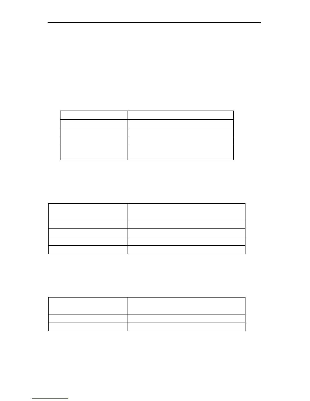
Jumper JP1 Position Function
RTD RTD Input
TC Thermocouple Input
Jumper JP2 Position Function
LOCK Sets a lock on programming
functions
Relay Acknowledge Enable (Display PCB)
Figure 34 on page 63 for PD755
Figure 35 on page 63 for PD756
Figure 36 on page 64 for PD757
Jumper
JP5 Position
Function
1 Enable relay 1 manual reset
2 Enable relay 2 manual reset
3 Enable relay 3 manual reset
4 Enable relay 4 manual reset
Fail-Safe Operation of Relays (Options PCB)
Figure 24 on page 57 for PD755
Figure 25 on page 58 for PD756
Figure 27 on page 59 for PD757
Jumper
J5 Position
Function
On Apply fail-safe function to all relays
Off Disable fail-safe function to all relays
Page 20
Large Display Temperature Meters Instruction Manual
20
Power Selection
Overview
Power Selection involves the following:
1. Changing to 230 VAC power if needed. 115 VAC is factory default on AC
powered models.
2. Labeling the meter as to how it will be powered: 115 VAC or 230 VAC.
Meters powered from 24 VDC are labeled as such at the factory.
Note:
Meters ordered to operate from 24 VDC do not require any special
setup; this option is not field selectable.
Installation and configuration must be undertaken by qualified servicing
personnel.
!
When servicing the PD756 in a hazardous area, all appropriate
hazardous area procedures must be followed.
!
All AC powered meters are shipped from the factory set for 115 VAC
power. Do not apply 230 VAC without first setting up the Digital
Temperature Meter to accept this voltage. Otherwise it will cause
damage to the meter and endanger personnel.
!
Disconnect power prior to performing the following procedures.
All three meters are field selectable for either 115 VAC or 230 VAC
power. Changing the voltage selection involves the removal of the front
cover and the Display PCB, then selecting 115V or 230V on switch S1
located on the Main PCB.
!
Observe polarity for DC powered meters. Applying voltage with reverse
polarity may damage the meter.
Do not apply an AC voltage to DC powered meters. Applying an AC
voltage to DC powered meters will result in damage to the meter and
endanger personnel.
Changing from 115 to 230 VAC Power
To access the 115/230 VAC switch it is necessary to remove the housing cover
and the Display PCB, see Disassembling the Meter, page 16.
Once the Display PCB has been removed, switch S1 is visible
. It is the large
black component with a red slide switch on the top, located next to the
transformer. For an illustration see:
Figure 31 on page 61 for PD755
Figure 32 on page 62 for PD756
Figure 33 on page 62 for PD757
For 115 VAC operation, the switch shows 115V; for 230 VAC it shows 230V.
Several setup steps are required and connections made while Display PCB is
removed, so it should not be reinstalled just yet. However, to avoid electric shock,
install Display PCB prior to applying power.
Page 21
Large Display Temperature Meters Instruction Manual
21
Labeling Meter for 115 VAC, 230 VAC or 24 VDC
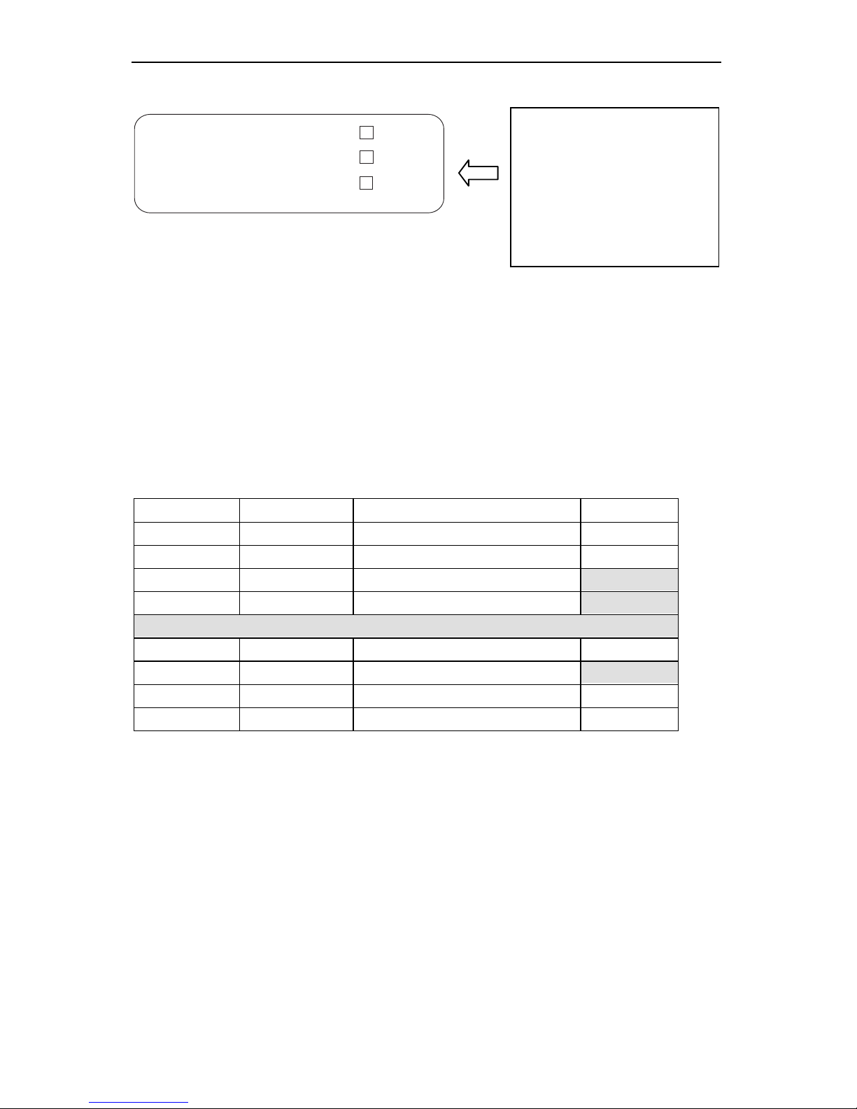
Figure 1. Input Power Label
Connections
Overview
The following connections are made to removable screw terminal connectors
supplied with each meter:
Power Connections
Signal Connections
Enter, Acknowledgement, and Hold Connections
Relays Connections
4-20 mA Output Connections
Connector Location Function Wire Size
J1 Main PCB Signal connections 12-22
J2 Main PCB Power connections 12-18
J3 Main PCB Connections to Options PCB
J4 Main PCB Connections to Display PCB
J1 Options PCB 4-20 mA output 12-22
J2 Options PCB Connections to Main PCB
J3 Options PCB Relays 1 & 2 connections 12-18
J4 Options PCB Relays 3 & 4 connections 12-18
A
label on top of the unit
contains a place for the
user to indicate if the unit is
powered from 115 or 230
VAC. User should mark the
appropriate box once the
desired power has been
selected on switch S1.
CAUTION
ALL AC POWERED UNITS ARE
SHIPPED FROM THE FACTORY
SET FOR 115 VAC
115 VAC
230 VAC
24 VDC
(SEE INSTRUCTION MANUAL TO CHANGE VOLTAGE SELECTION)
Page 22
Large Display Temperature Meters Instruction Manual
22
Wiring Instructions
For connector locations, refer to:
Figure 31 on page 61 for PD755
Figure 32 on page 62 for PD756
Figure 33 on page 62 for PD757
1. All field connections to be made with insulated copper wire, either solid or
stranded. Tighten all screw terminals to 4.5 lb-in (0.5 Nm).
Strip length = ¼ in (7 mm). DO NOT
pre-treat wire with solder.
2. Terminals L1(V+), L2(V-) on J2, Main PCB, Earth Ground, and terminals
1-6 on J3-J4, Options PCB: Use AWG #12-18 wire, 600 volt, 60°C.
Connect only one wire to each terminal.
3. Terminals EN, AK, H, CM, P-, P+, EX, +, –, on J1 Main PCB and
terminals +, - on Options PCB: Use AWG #12-22 wire, 150 volt, 60°C. If
using AWG #20 or smaller wire, up to two wires may be connected to each
terminal. If using AWG #18 or larger wire, only one wire may be connected to
each terminal.
4. Install conduit hubs to the enclosure cable input ports. To maintain NEMA 4X
rating use only UL/CSA watertight conduit hubs.
5. Feed all wires through the enclosure cable input ports.
6. Remove one connector at a time from the headers and connect the wires to
the connector.
7. After wiring a connector, insert it back into the header.
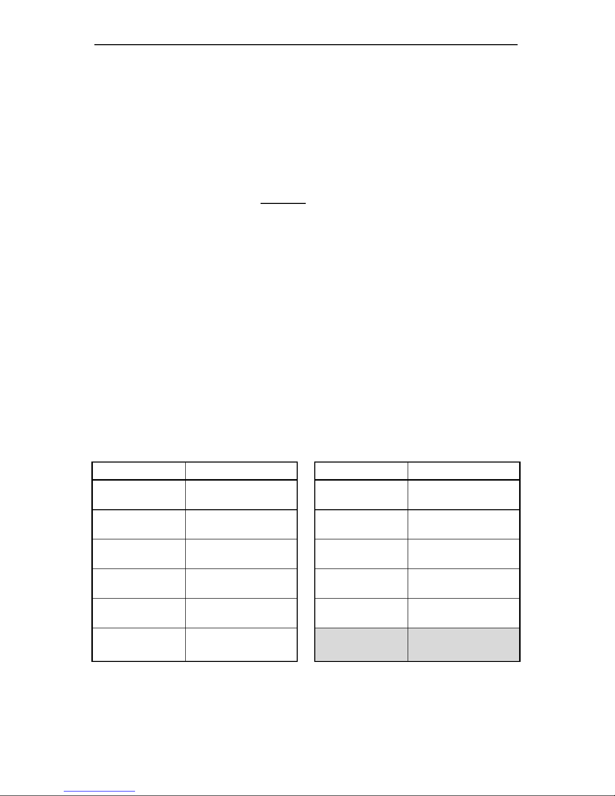
Terminals Designation
Terminal Description Terminal Description
L1, L2, Gnd AC input power
P+, P- 24 VDC supply
V+, V- DC input power
EX Excitation for RTD
EN External Enter +, -
(Main PCB)
TC & RTD input
AK External relay
acknowledge
+, -
(Options PCB)
4-20 mA output
(see page 27)
H Hold reading 1-6
(Option PCB)
Relays 1-4
(see page 27)
CM Common (return) for
AK, EN, & H
Page 23
Large Display Temperature Meters Instruction Manual
23
Power Connections
!
When servicing the PD756 in a hazardous area, all appropriate
hazardous area procedures must be followed.
!
Refer to Changing from 115 to 230 VAC Power, page 20 to make sure meter is
set up to accept proper voltage before applying power.
!
Disconnect power to the meter before making any connections.
!
Do not connect Power or Earth Ground to any unused or CM terminals.
Connecting 230 VAC with 115 VAC selected will result in damage to the
instrument as well as endanger personnel. Connecting AC power when meter is
set up for DC power will result in damage to the instrument as well as endanger
personnel.
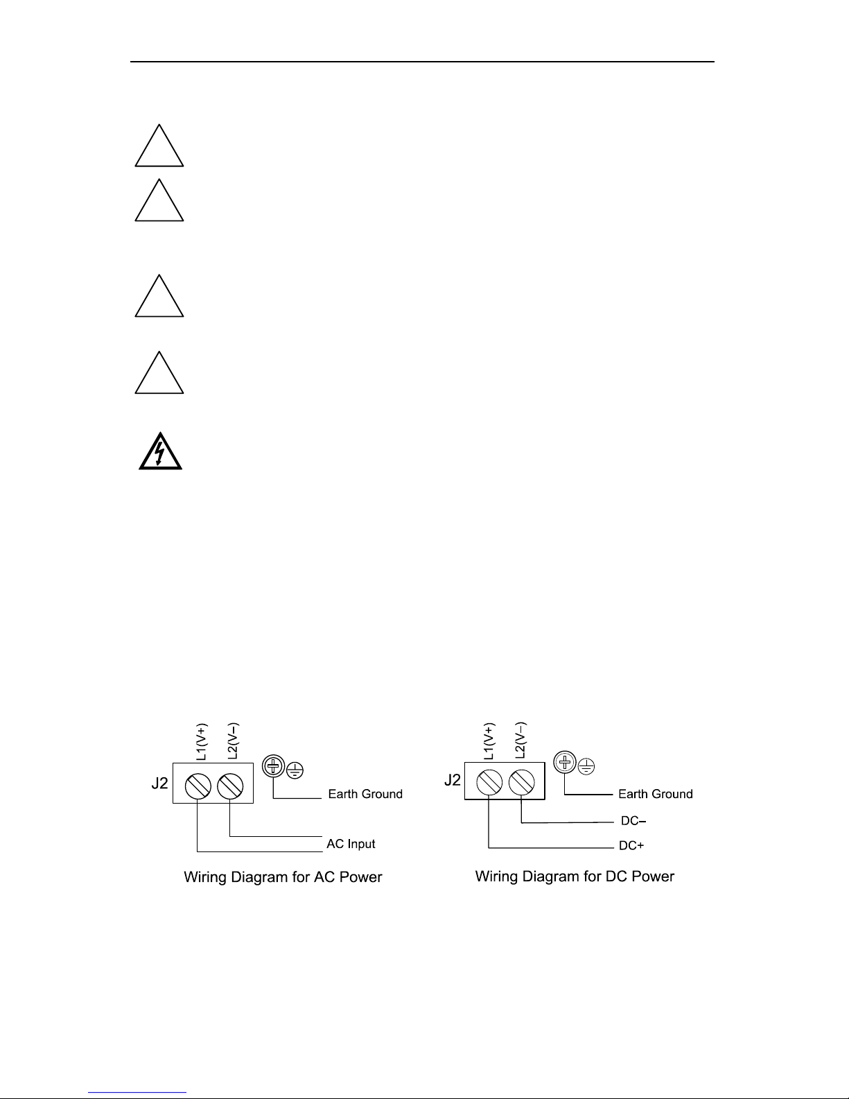
Connect power to terminals L2(V-) and L1(V+) on screw terminal connector J2,
located near the transformer on the Main PCB. Connect Earth Ground to screw
terminal marked with Ground symbol located on enclosure’s base for PD756 and
757. Ground terminal for PD755 is located on J2 connector.
Figure 31 on page 61 for PD755
Figure 32 on page 62 for PD756
Figure 33 on page 62 for PD757
Figure 2. Input Power Connections for 756 and 757
Notice:
• Primary voltages must not be accessible to the user.
• Primary wires must be installed in accordance to the applicable standards.
• Keep the primary wires separated from signal cables.
Page 24
Large Display Temperature Meters Instruction Manual
24
Signal Connections
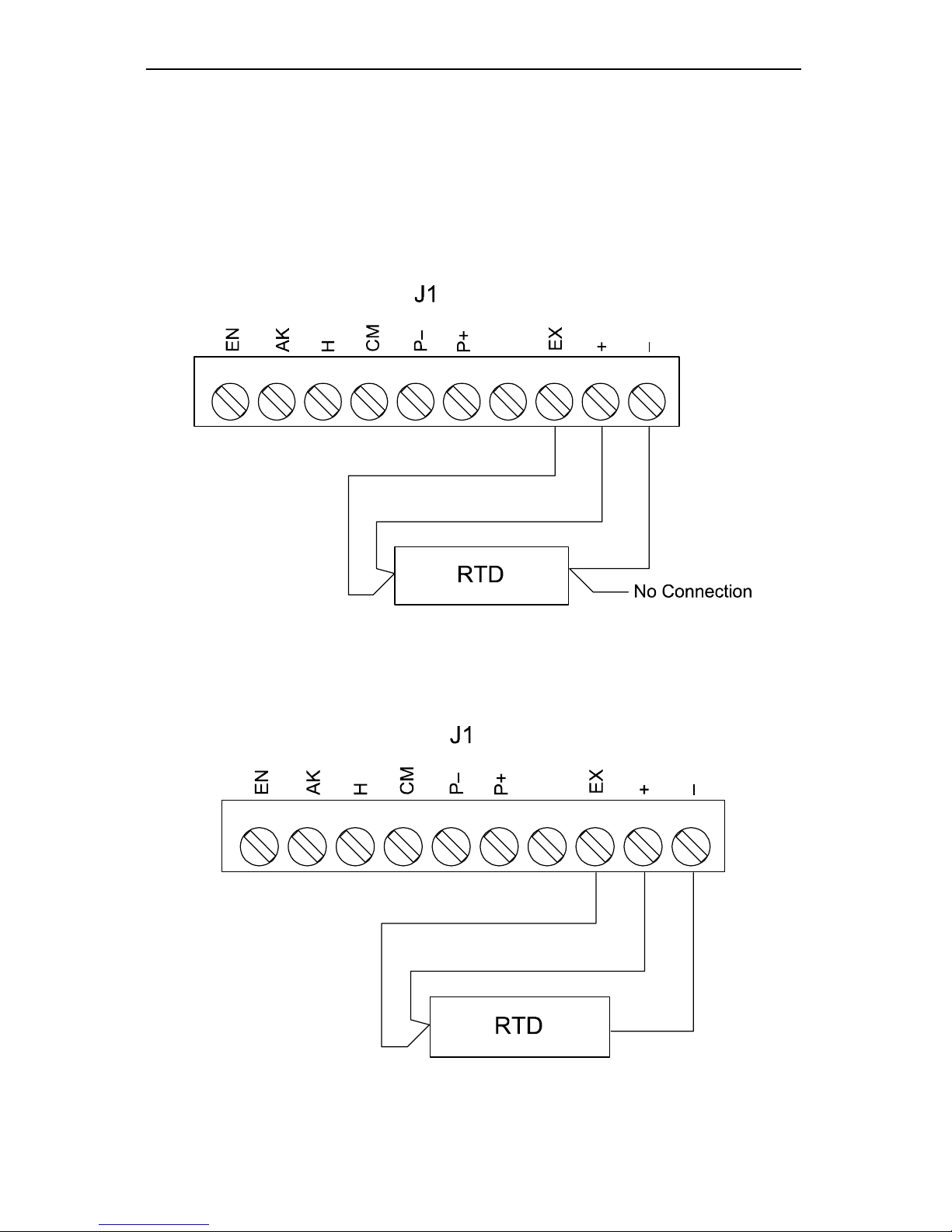
Signal connections are made to a 10 position connector J1 on the Main PCB.
This connector also includes connections for Enter, Acknowledgement, Hold
Reading, and Common. For location of J1, refer to:
Figure 31 on page 61 for PD755.
Figure 32 on page 62 for PD756.
Figure 33 on page 62 for PD757.
Figure 3. Four-Wire RTD Connections
Figure 4. Three-Wire RTD Connections
Page 25
Large Display Temperature Meters Instruction Manual
25
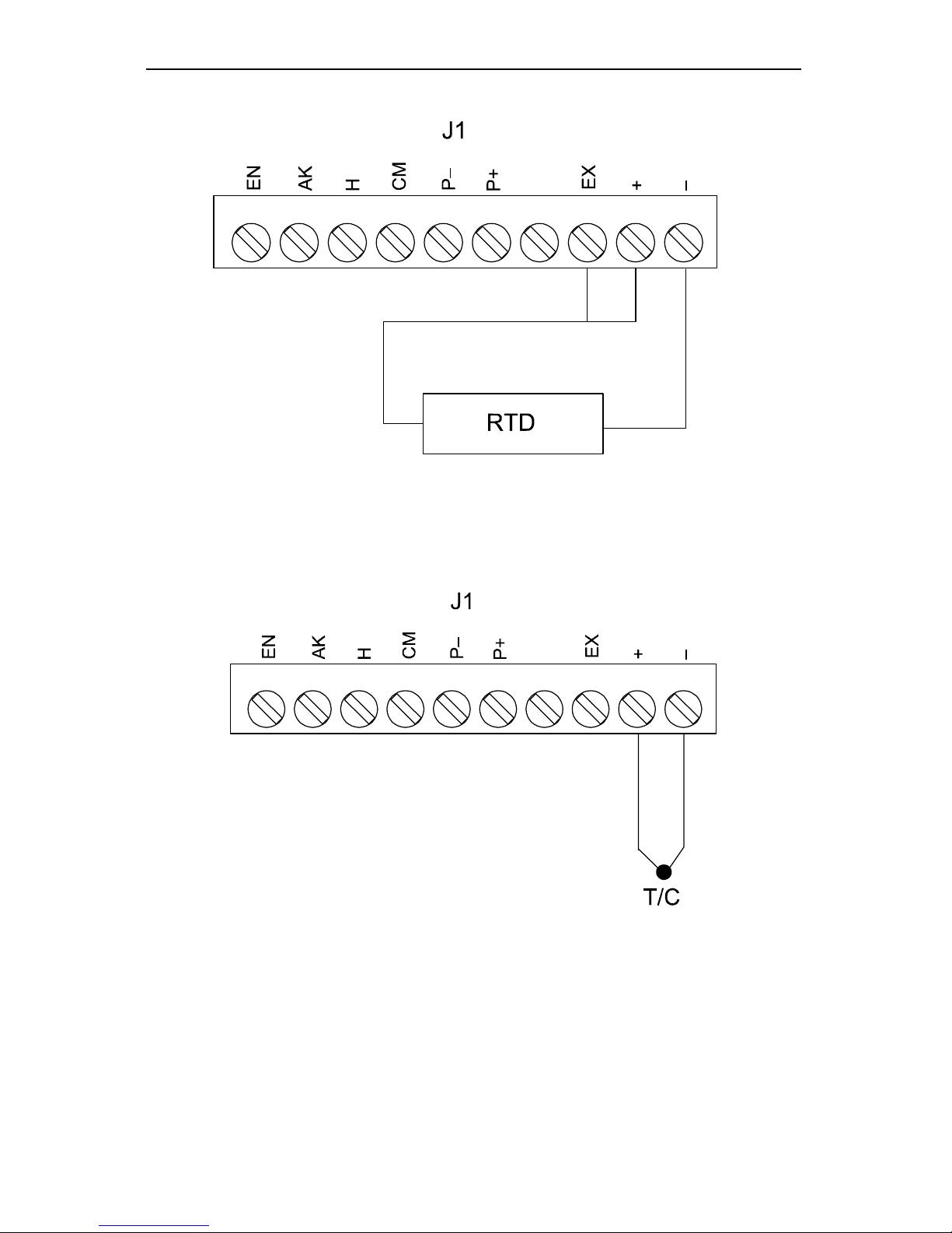
Figure 5. Two-Wire RTD Connections
Figure 6. Thermocouple Connections
Page 26
Large Display Temperature Meters Instruction Manual
26
Enter, Acknowledgement, and Hold Connections
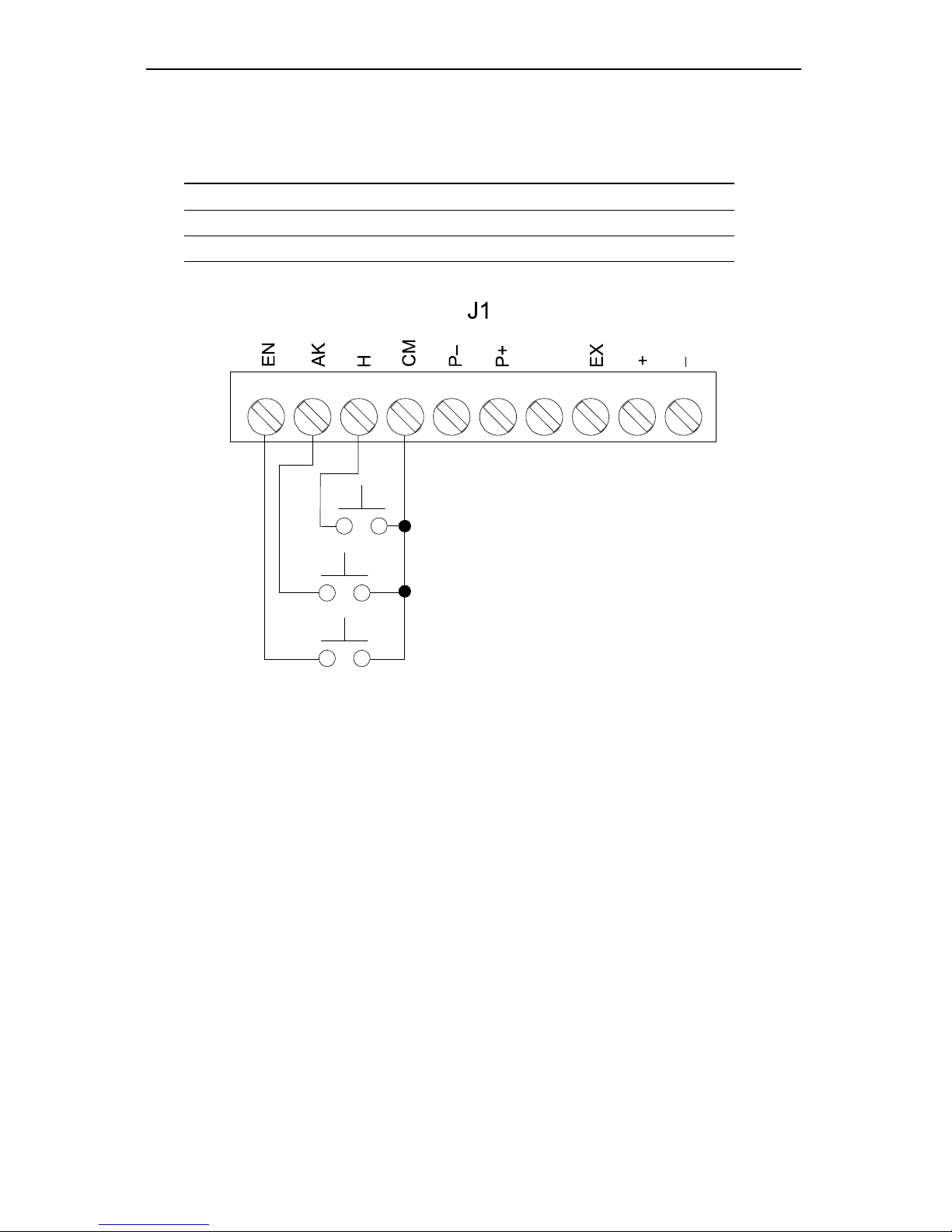
Enter, acknowledgement, and hold terminals on J1 (Main PCB) provide a
convenient method to remotely access the following functions:
Terminal Function
EN Programs meter via the front panel menu
AK Acknowledges or resets relays, exit menu scroll
H Holds the temperature reading
Hold reading switch
ACK switch
ENTER switch
Figure 7. External Control Connections
Page 27
Large Display Temperature Meters Instruction Manual
27
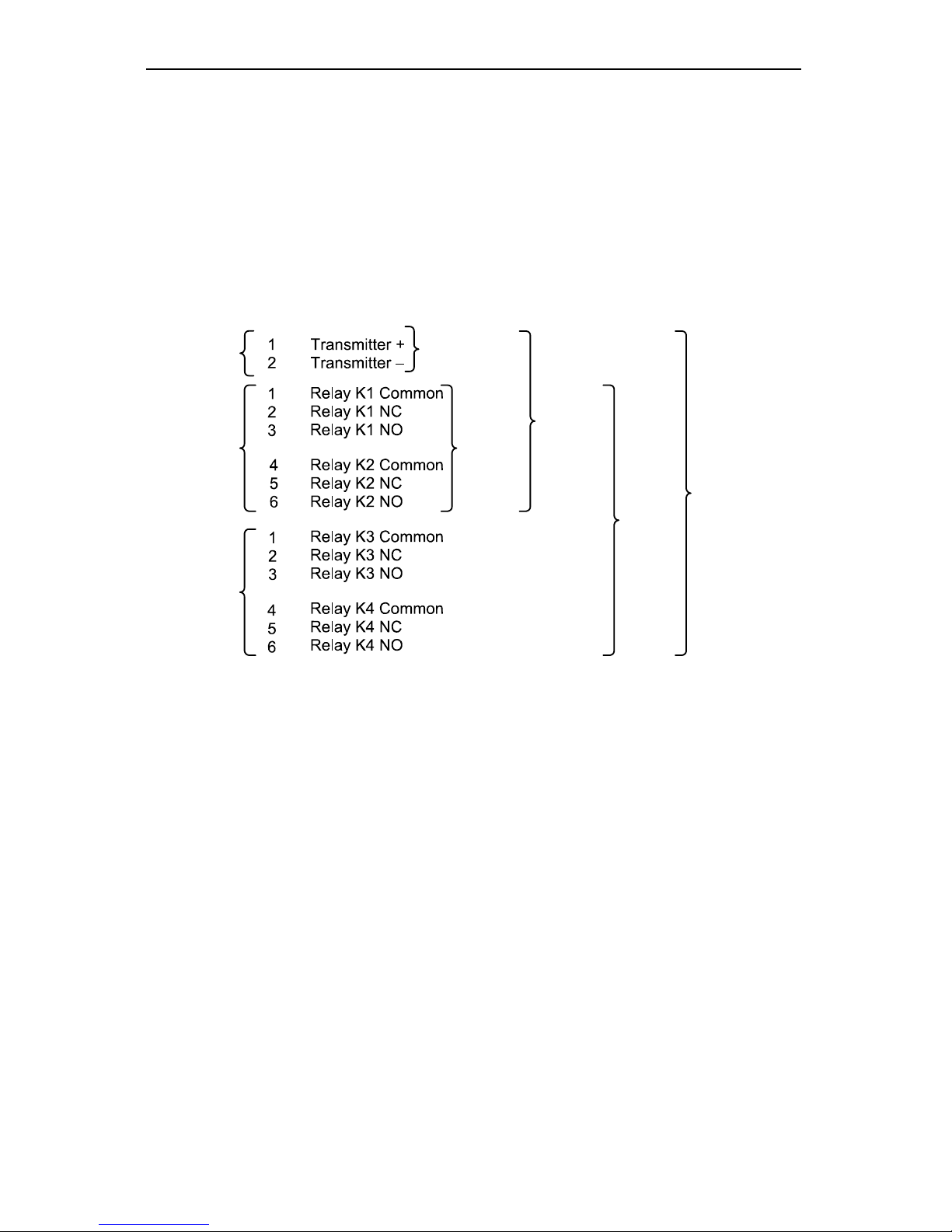
Optional Relays & 4-20 mA Output Terminals
Depending on model number, Options PCB may contain 2 or 4 relays and/or an
isolated 4-20 mA output transmitter. Relay connections are made to removable
screw terminal connectors located at J3 and J4 on the Option PCB. Connections
for the isolated 4-20 mA output option are made to J1 on the Options PCB. For
location of connectors, refer to:
Figure 24 on page 57 for PD755.
Figure 25 on page 58 for PD756.
Figure 27 on page 59 for PD757.
J1
J3
J4
PD375
PD475
PD376
PD476
PD374
PD474
PD377
PD477
PD378
PD478
Figure 8. Relay and 4-20 mA Output Terminals
Page 28
Large Display Temperature Meters Instruction Manual
28
Isolated 4-20 mA Output Transmitter Connections
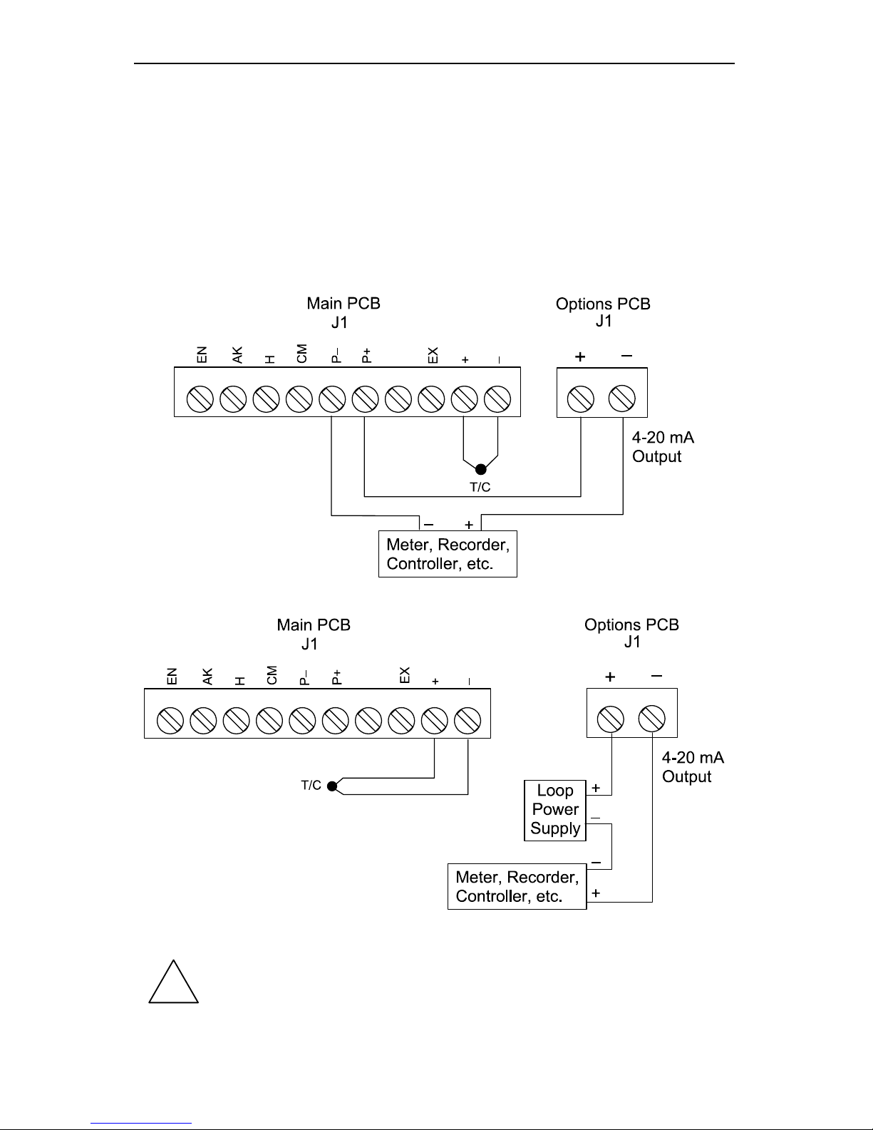
The Digital Temperature Meter can be equipped with an optional isolated 4-20
mA output transmitter that can be programmed to produce a 4-20 mA signal for
virtually any temperature span displayed. For best performance, a 500 count
span is recommended between the 4 and 20 mA outputs. (Ex. 0.0°C = 4 mA,
50.0°C = 20 mA).
The following diagrams illustrate the 4-20 mA output signal being powered from
the Digital Temperature Meter’s internal power supply (AC powered meters only)
and by an external power supply.
Figure 9. Output Loop Powered by Meter
Figure 10. Output Loop Powered from External Power Supply
!
If the output loop is powered by an external supply, the loop power
supply must be turned on before the meter is turned on. Otherwise,
the output loop signal may be incorrect.
Page 29
Large Display Temperature Meters Instruction Manual
29
Programming
Overview
This section of the manual deals with programming the following aspects of the
meter:
Basic Meter
Alarm Set Points
4-20 mA Output
Lockout Jumper
The Digital Temperature Meter is programmed after setting three jumper arrays,
see Jumper Configuration on page 19. The ENTER button is used to program
all the meter functions and to display useful information.
The jumper arrays are used for setting the input (thermocouple or RTD), lockout,
relay acknowledge enable (ACK), and relay fail-safe operation.
Jumper Arrays
Jumper Array Function Label Location
Input signal T/C or RTD JP1 Main PCB
Lockout JP2 Main PCB
Relay ACK enable JP5 Display PCB
Fail-safe J5 Options PCB
For jumper array location see:
Figure 31 and Figure 34 on pages 61, 63 for PD755.
Figure 32 and Figure 35 on pages 62, 63 for PD756.
Figure 33 and Figure 36 on pages 62, 64 for PD757.
If the optional relay PCB is installed, it is best to program the fail-safe jumper (J5
on Options PCB) for the desired operation before reassembling the Display PCB
because this jumper is not accessible once the Display PCB is installed.
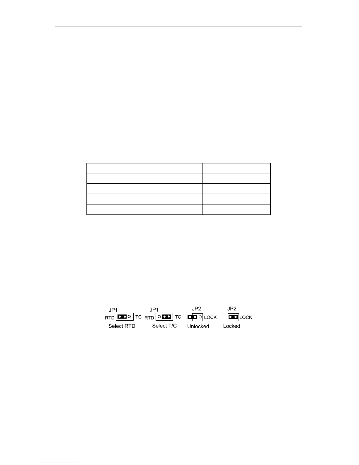
Select Type of Input Signal T/C or RTD
The Digital Temperature Meter can accept either thermocouples or RTD inputs,
using jumper JP1 located on the Main PCB.
Figure 11. JP1 Input Signal Selection Array.
The Digital Temperature Meter can be programmed to restrict personnel from
making changes to the programmed parameter settings; this is accomplished by
installing a jumper over LOCK pins on JP2.
Page 30
Large Display Temperature Meters Instruction Manual
30
ENTER Button Functionality
The ENTER button is used to program the meter for various functions, is located
on the Display PCB and is labeled SW2. The ENTER button on PD755 can be
accessed from the front panel. The ENTER button on models 756 and 757 can
only be accessed with the front panel removed. The ENTER button can also be
accessed by wiring a normally open pushbutton switch across terminals EN and
CM on connector J1 located on the Main PCB (see Figure 7 on page 26).
ACK Button Functionality
The ACK button is used to acknowledge the relays when the meter is in reading
mode and to quit the menu scroll in programming or diagnostic. If ENTER has
been pressed and the meter is scrolling down the menu, pressing ACK button
returns meter to reading mode, it does not acknowledge relays during menu
scroll.
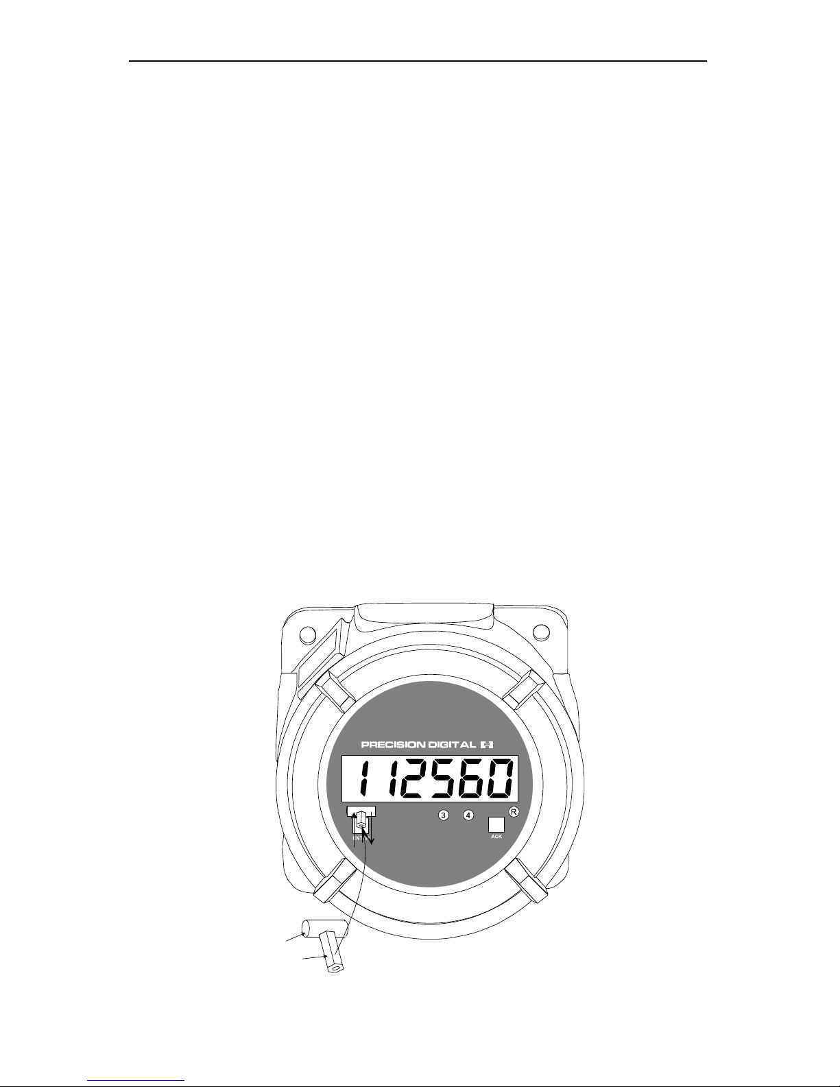
Magnetic Reed Switch Functionality
The PD756 has two magnetic reed switches located above the ENTER and ACK
buttons. The reed switches allow the user to program and operate the meter
without having to remove the enclosure cover.
To operate the reed switches, move the magnet assembly (PDA-MAG) toward
and away from the glass window, just above the ENTER and ACK buttons. The
action is detected when the magnet is moved away from the glass window.
Moving the magnet toward and away from the glass window produces the same
results as pressing the front panel buttons.
The PD756 can be programmed and operated in three different ways:
1. Using front panel push buttons.
2. Using external push buttons wired to J1 connector. Explosion-proof control
stations are required when used in a hazardous area.
3. Using magnet assembly to operate the reed switches.
PDA-MAG (Optional)
Move magnet toward and away
from cover to operate ENTER
and ACK buttons
Magnet
Handle
Figure 12. Reed Switch Operation
Page 31

Large Display Temperature Meters Instruction Manual
31
General Programming Description
When power is applied to the meter, the display flashes 188888, then it displays
the temperature from the sensor.
To program the meter lockout jumper JP2 must be removed.
After pressing the ENTER button, the display will scroll through the following
functions in the order shown:
Display Type of Function
HI t
Displays maximum temperature
LO t
Displays minimum temperature
CALIb
Calibrates meter for selected input type.
OFFSEt
Sets offset value to the input, negative or positive
type
Sets the type of T/C or RTD to be used
F or C
Sets temperature scale, Fahrenheit or Celsius
SetuP
Sets alarm set points for latching or non-latching operation
SetPtS
Sets alarm set and reset points.
output
Sets 4 and 20 mA output points, if this option is installed.
dIA9
Displays parameter settings one at a time for diagnostic
purposes.
Five Basic Digit/Display-Setting Instructions
1. If flashing display is OK, press ENTER to accept it, before display stops
flashing.
2. If flashing display is not OK, (or if ENTER was not pressed in time to accept
it), wait for the first digit to flash.
3. If a flashing digit is OK, press ENTER to accept it, before it starts to scroll.
4. If a flashing digit is not OK, (or if ENTER was not pressed in time to accept
it) wait for digit to scroll, and press ENTER when OK.
5. Digits will scroll until ENTER is pressed. When a digit is accepted by
pressing ENTER, next digit flashes.
Page 32
Large Display Temperature Meters Instruction Manual
32
Programming the Basic Meter
Programming the basic meter consists of selecting the type of T/C or
RTD and selecting the temperature scale °F or °C.
The Digital Temperature Meter must be programmed for the type of
thermocouple or RTD it is to accept. Selecting the wrong type will cause an
incorrect temperature to be displayed.
Connect the thermocouple or RTD to J1 on the Main PCB.
Using the TYPE menu, enter a number from 0 to 10, this number defines the type
of thermocouple or RTD input required and the display resolution. The following
table is used to define the types:
Type
Number
Type of Input Range Accuracy
0 Type J T/C
–328° to 1382° F
–200° to 750°C
±2°F
±1°C
1 Type K T/C
–328° to 2498°F
–200° to 1330°C
±2°F
±1°C
2 Type T T/C
–330° to 760°F
–200° to 404°C
±2°F
±1°C
3 Type T T/C
(0.1°)
–330.0° to 760.0°F
–200.0° to 404.0°C
±2°F
±1°C
4 Type E T/C
–328° to 1832°F
–200° to 1000°C
±2°F
±1°C
5 Type R T/C
32° to 3213°F
0° to 1767°C
±5°F
±3°C
6 Type S T/C
40° to 3214°F
4° to 1768°C
±6°F
±3°C
7
100 Ω RTD
(0.00385, 0.1°)
–328.0° to 1382.0°F
–200.0° to 750.0°C
±0.7°F
±0.4°C
8
100 Ω RTD
(0.00392, 0.1°)
–328.0° to 1382.0°F
–200.0° to 750.0°C
±0.7°F
±0.4°C
9
100 Ω RTD
(0.00385, 1°)
–328° to 1382°F
–200° to 750°C
±1°F
±1°C
10
100 Ω RTD
(0.00392, 1°)
–328 to 1382°F
–200° to 750°C
±1°F
±1°C
Page 33
Large Display Temperature Meters Instruction Manual
33
Selecting Type of T/C or RTD (TYPE)
After power is applied to the meter, the display will indicate a temperature reading
which might be incorrect since the meter could be programmed for a different
type of thermocouple or RTD.
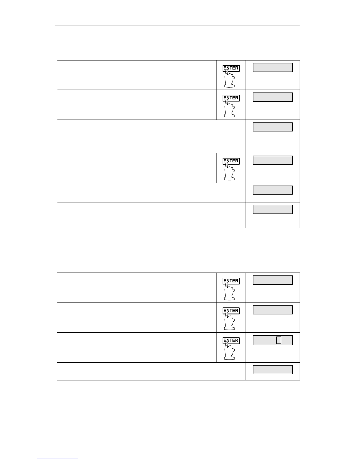
Press ENTER to begin scrolling through the
functions.
62f
When type (type) appears, press ENTER.
type
The meter now displays the type choices starting at the
previously programmed number; here it is type 6. The
number starts to increase up to type 10 and then goes to
type 0. Select the type number from the previous table.
Type 6
Press ENTER when the desired type number
appears. In this case, it is type 0 for type J T/C.
Type 0
The meter will then display F or C
Press ENTER to select scale.
F or C
Press the ACK button to quit menu scroll and return to
indication mode. The meter is now displaying the process
temperature accurately.
72f
Select °F or °C (f or C)
The Digital Temperature Meter will display temperature in either
Fahrenheit or Celsius scale.
Set or change the temperature scale
Press ENTER to begin scrolling through the
functions.
72f
When f or C (°F or °C) appears, press
ENTER.
F or C
The display will show F for Fahrenheit and C for
Celsius; they will flash alternately. Select one
when it is flashing by pressing ENTER.
F or C
The display will indicate the temperature in the selected
scale.
22{
Note:
Whenever a programmed setting is changed in the basic meter, the
offset value is reset to zero and the max/min readings are reset to the
actual temperature reading. Alarm setup, set points, and 4-20 mA output
programming do not reset these settings.
Page 34

Large Display Temperature Meters Instruction Manual
34
Alarm Setup and Set Points Programming
Overview
The Digital Temperature Meter is available with four alarm points and
corresponding front panel status LEDs as a standard feature. The front panel
LEDs are useful for alarm applications that require visual notification only. For
applications that require relay contacts, such as driving external alarm devices or
on/off temperature control, the Digital Temperature Meter can be equipped with
either two or four relays. Any of these relays may be assigned to set and reset at
predetermined temperatures. Each relay can be set up for latching or nonlatching operation independently.
Programming the relays involves four steps:
1. Setting the relay manual reset (ACK enable) jumpers.
These jumpers (JP5) are located on the Display PCB and determine if a
relay can be manually reset.
2. Setting the fail-safe jumper (J5).
Fail-safe mode (default): In the alarm condition, the NC contacts are
connected to the Common (C) contacts of the relays. The fail-safe operation
can be disabled, by removing jumper J5 located on the Options PCB.
3. Setting the alarm set points for latching or non-latching relay operation using
SETuP menu.
4. Setting set and reset points using
SEtPtS menu.
a. Setting set points for alarms.
b. Setting reset points for alarms.
Set Relays for Manual or Automatic Reset
Jumper array JP5 located on the Display PCB is used to program the relays so
they can be reset manually. For location of JP5 on the Display PCB, see:
Figure 34 on page 63 for PD755.
Figure 35 on page 63 for PD756.
Figure 36 on page 64 for PD757.
Set Relays for Fail-Safe Operation
In fail-safe mode, the relay coils are energized and the Normally Open (NO)
contacts are connected to the Common (C) contacts under normal operation.
During an alarm condition, the relay coils are de-energized, the Normally Closed
(NC) contacts are connected to the Common (C) contacts. During power failure,
the relay contacts reflect an alarm condition.
Removing jumper J5 disables the fail-safe operation. J5 is located on the Options
PCB next to the J2 connector. For location of J5 on the Options PCB, see:
Figure 24 on page 57 for PD755
Figure 25 on page 58 for PD756
Figure 27 on page 59 for PD757
If fail-safe mode is disabled, operation of the relay contacts is opposite to the
one described in the previous paragraph.
Page 35
Large Display Temperature Meters Instruction Manual
35
Setup for Latching or Non-Latching Relays (SetuP)
Each alarm set point can be set up for latching or non-latching relay
operation independently. This means that a combination of latching and
non-latching relays could be used in this meter. Factory default is nonlatching operation for all relays.
Note To simplify programming, write down the desired programming
values prior to attempting to program the meter. The Programmed
Parameter Settings form, located on page 69, provides a
convenient method to record the user settings; it also provides the
factory setting for most of the programmable parameters.
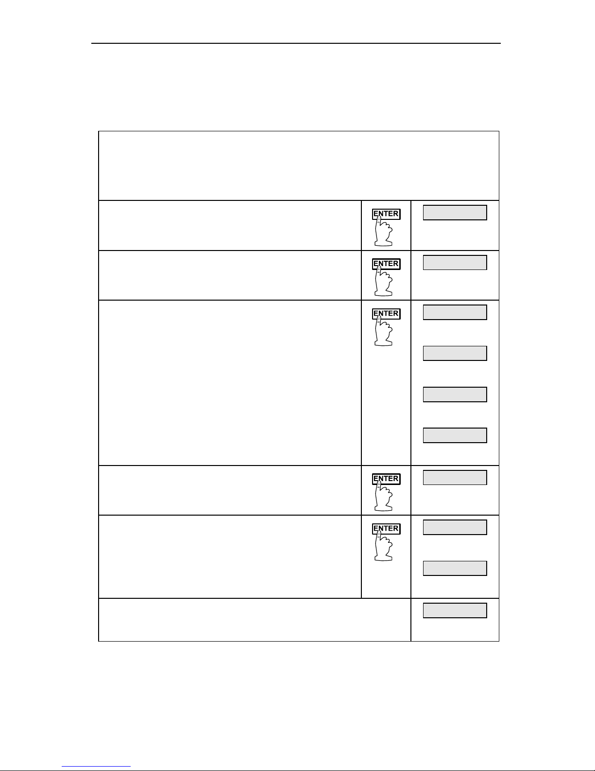
Press ENTER to begin scrolling through the
functions.
72f
When setup ( SEtuP) appears, press ENTER.
setup
The display scrolls through set 1, Set 2, set
3
, and set 4 for set point 1 through set point 4
setup. Press ENTER to select latching or nonlatching relay operation for desired set point. If
ENTER is pressed while scrolling set points,
LatCH is displayed for 3 seconds.
set 1
then
set 2
then
set 3
then
set 4
Press ENTER to program set point for latching or
non-latching relay operation when LatCH is
displayed.
LAtCH
Y or n flashes alternately. Press ENTER when
appropriate letter is flashing to make selection.
After selection is made, display shows next set
point or next menu function.
Y or n
then
SEtPts
Press ACK button to exit menu scroll and return to reading
mode or wait until meter scrolls through the entire menu.
The display will return to indicate the temperature.
72F
Page 36

Large Display Temperature Meters Instruction Manual
36
Alarm Set and Reset Points Programming
Alarm set and reset point values are programmed under the set points (SEtPtS)
menu, one at a time, starting with alarm #1 set point.
The four discrete LEDs on the display indicate which alarm point is being
programmed. There are two LEDs on the display PCB labeled S and R, they
indicate whether a set or reset point is being programmed
Each alarm will have a set point programmed first, and then the reset point is
programmed.
Each alarm set point may be programmed for either a high alarm or a low alarm
with 0-100% deadband.
To program a high alarm:
Program the set point above the reset point.
To program a low alarm:
Program the set point below the reset point.
To program the alarm deadband:
Program the reset point above or below the set point by an amount
equal to the desired deadband value.
Example:
Alarm 2 is a high alarm that trips at 1500° and has a deadband
of 100°.
Alarm 2 set point is set at 1500° and its reset point at 1400°.
Page 37
Large Display Temperature Meters Instruction Manual
37
Programming Alarm Points Using Set Points (setpts) Menu
Note To simplify programming, write down the desired programming values
prior to attempting to program the meter. The Programmed
Parameter Settings form, located on page 69, provides a convenient
method to record the user settings; it also provides the factory setting
for most of the programmable parameters.
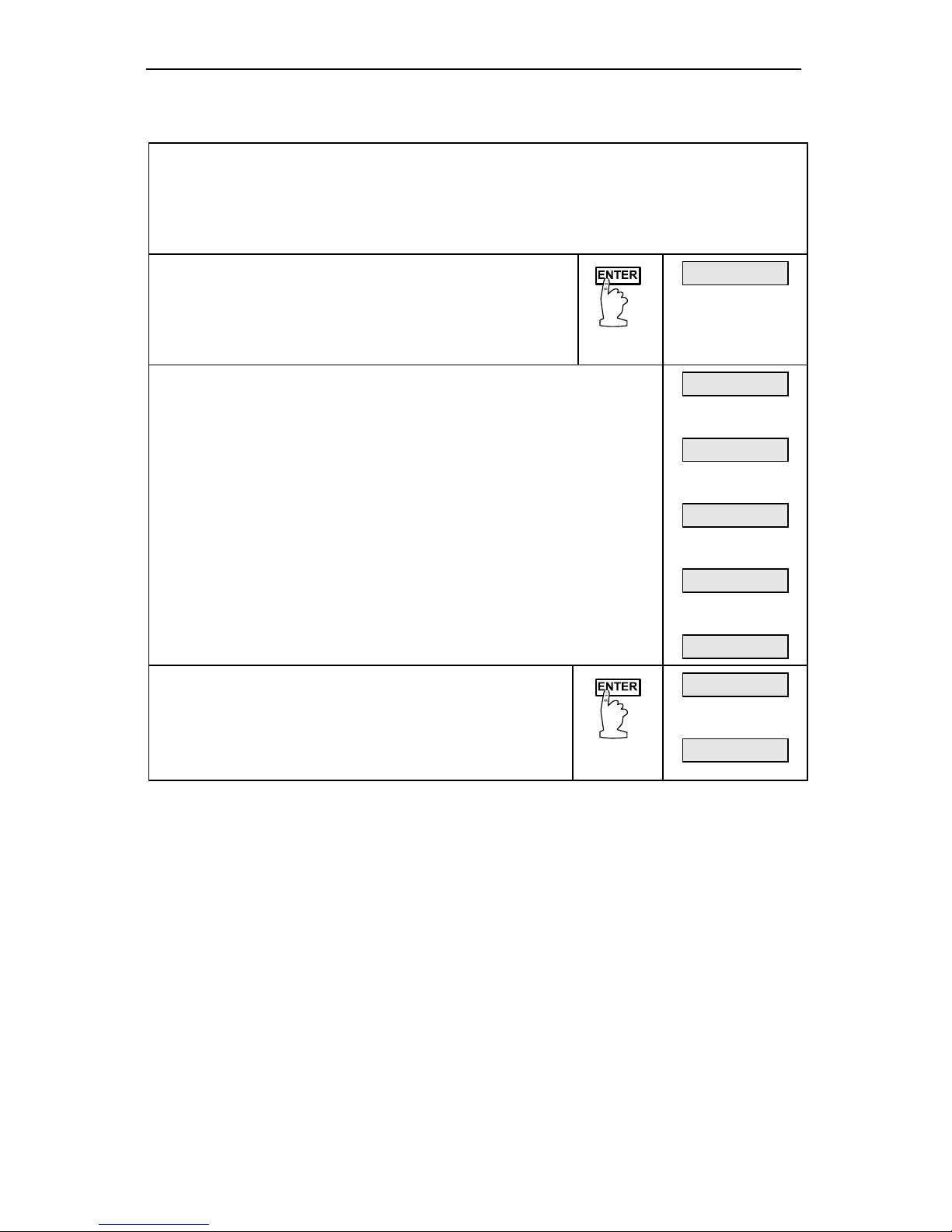
Press ENTER, then press ENTER again when set
points (SEtPtS) function appears. The display will
scroll through the set points. Press ENTER when
the desired set point is displayed to program that
set point.
SEtPtS
To program set points values
The display scrolls through
set 1, Set 2, set 3, set 4,
for alarm set point 1 through alarm set point 4. Press ENTER
when desired set point appears.
After
Set 4 is displayed or programmed, the meter will exit
the
SetptS (set points) menu and move to the next
programming menu.
output will be displayed, if 4-20 mA transmitter output
option is installed.
SEt 1
then
SEt 2
then
SEt 3
then
SEt 4
then
outPut
If ENTER is pressed while a set point is shown,
the display will then show a flashing number.
Program the desired set point value per
Five Basic Digit/Display-Setting Instructions on
page 31.
SEt 1
then
00100F
Alarm Set and Reset Programming Confirmation
To verify that the alarm set and reset points have been programmed as desired,
press ENTER, and press ENTER again when sEtPtS appears, the display will
scroll through set points 1 through 4. Press ENTER when the desired set point is
shown. Before the display stops flashing set point value, press enter to advance
the display to reset point.
Page 38
Large Display Temperature Meters Instruction Manual
38
Isolated 4-20 mA Output Transmitter Option
The Digital Temperature Meter can be equipped with an optional isolated 4-20
mA output transmitter that can be programmed to produce a 4-20 mA signal for
virtually any temperature span displayed. For best performance, a 500 count
span is recommended between the 4 and 20 mA outputs. (Ex. 0.0°C = 4 mA,
50.0°C = 20 mA).
Figure 9 and Figure 10 on page 28 show the 4-20 mA output signal being
powered from the Digital Temperature Meter’s internal 24V power supply (AC
powered meters only) and by an external power supply.
To program the 4-20 mA output, a temperature display is programmed to
produce the 4 mA signal. Another temperature display, (higher or lower than the
one set for the 4 mA point), is programmed to produce the 20 mA signal. The
output will be linear as the temperature changes from the 4 mA setting to the 20
mA setting.
Example: If the 4 mA point is set for 0°, and the 20 mA point is set for 1000°, the
output will be 6 mA when the temperature display reads 125°.
Note: The 4-20 mA output is driven by the number been displayed. It doesn’t
adjust itself if the temperature scale is changed.
4-20 mA Output Programming (output)
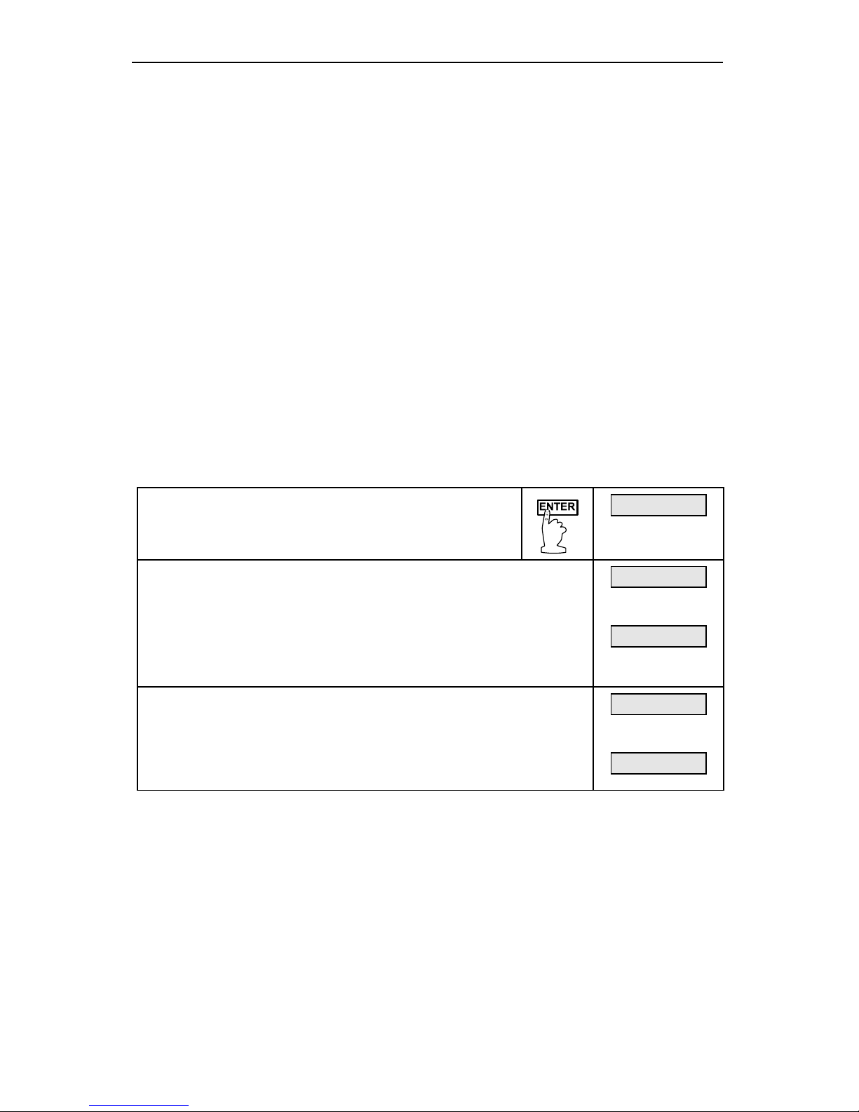
Press ENTER, then press ENTER again when the
output (output) menu appears.
output
Set the display for the value at which 4 mA is produced
The green LED labeled “4” will be on indicating the meter is
ready to accept the value at which 4 mA is produced. After
the display corresponding to 4 mA is accepted, an LED
labeled “20” turns on. For instructions, see
Five Basic Digit/Display-Setting Instructions on page 31.
00032f
final
00000f
Set the display for value at which 20 mA is produced
The green LED labeled “20” will now be on indicating the
meter is ready to accept the value at which 20 mA is
produced. Program this value in the same fashion as was
done above.
00100f
final
01000f
4-20 mA Output Programming Confirmation
The values that have been programmed to produce the 4 and 20 mA outputs can
be quickly checked to make sure they are the desired values. To do this, access
the
outPut routine by pressing ENTER, and then pressing ENTER again when
outPut appears.
The green “4” LED illuminates indicating the meter is displaying the value at
which it will produce a 4 mA output. Confirm that this is the desired value. Press
ENTER, the green “20” LED illuminates indicating the meter is displaying the
value at which it will produce a 20 mA output. Confirm that this is the desired
value. Press ENTER (within 3 seconds) before the entire display stops flashing
and the meter returns to indication mode.
Page 39
Large Display Temperature Meters Instruction Manual
39
Input Offset Adjustment (OFFSEt)
This parameter allows the user to select an offset to the input signal being
displayed. Offset values can be either positive or negative and can be any
number within the range of the display. The offset value is programmed through
the offset (
OFFSEt) menu.
The offset feature can be useful to compensate for errors due to thermocouple
junctions or excessive lead wire resistance in RTDs.
The offset value is factory default to zero. The offset value is automatically reset
to zero whenever a programmed parameter, related to the temperature display, is
changed.
To program the offset value follow instructions described in,
Five Basic Digit/Display-Setting Instructions on page 31.
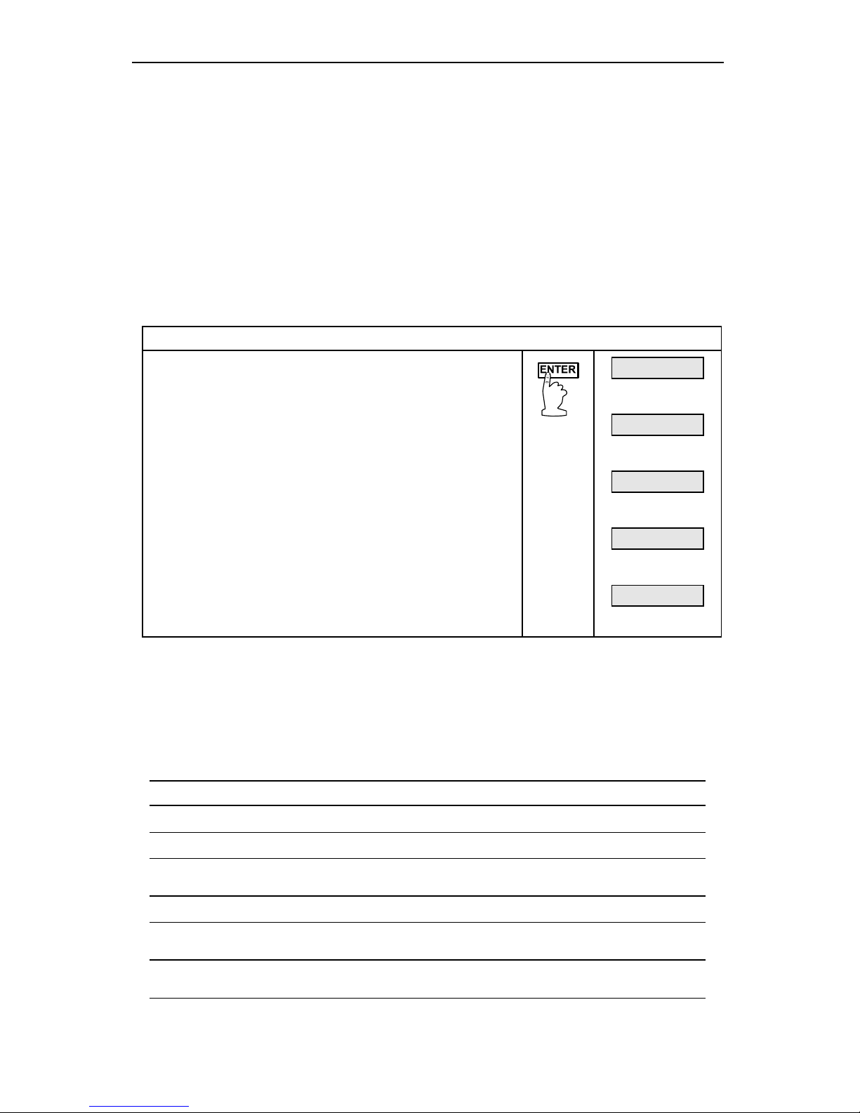
Program input offset
Press ENTER, when OFFSEt appears press
ENTER again to program input offset value.
Example:
If display reads 85°F when the actual temperature
is 80°F, program an offset value equal to -5°F.
Then the display will indicate the actual
temperature.
85F
then
OFFSEt
then
00000F
then
-0005F
then
80F
Lockout Jumper
The Lockout jumper is used to restrict modification of calibration and
programming values. It is labeled “LOCK” on JP1 (see Figure 11 on page 29).
The lockout feature allows viewing only of the alarm settings and temperature
points programmed to produce the 4 and 20 mA output signals.
The following menu functions are still available with the lockout jumper installed.
Display Type of Function
HI t
Displays maximum temperature.
LO t
Displays minimum temperature.
CLEAr
Clears (resets) maximum or minimum temperatures
reached by the process.
SEtPtS
Displays alarm set and reset points.
output
Displays 4 and 20 mA output points, if this option is
installed.
dIA9
Displays parameter settings one at a time for diagnostic
purposes. Press ACK to exit diagnostic menu at any time.
Page 40

Large Display Temperature Meters Instruction Manual
40
OPERATION
Overview
The Large Display Temperature Meter accepts the J, K, T, E, R, and S
thermocouples and 100 Ω platinum RTDs as inputs. The meter will display the
temperature in either Fahrenheit or Celsius scales on a 4½ digit display. Options
include up to four relays for external switching at alarm points as well as an
isolated 4-20 mA transmitter output.
The front panel consists of six seven-segment LEDs as well as eight
programming/operational LEDs. The programming/operational LEDs provide the
following indication:
LED During Programming During Operation
1 Alarm 1 Alarm 1
2 Alarm 2 Alarm 2
3 Alarm 3 Alarm 3
4 Alarm 4 Alarm 4
S Set point indicator None
R Reset point indicator None
4 4 mA output indicator None
20 20 mA output indicator None
Refer to Figure 37 on page 65 for PD755.
Refer to Figure 38 on page 65 for PD756.
Refer to Figure 39 on page 65 for PD757.
The four alarm status LEDs indicate alarm condition only and do not represent
relay status when set points are set up for non-latching relay mode. For instance,
if alarm 1 is programmed for a high alarm at 500 with manual reset of the relays.
If the operator resets the relays when the display reads 650, LED #1 will stay on
until the display falls below 500.
Set points set up for latching relay mode will reflect the status of the LEDs,
regardless of the status of the alarm condition. For instance, when a latching
relay is acknowledged the corresponding status LED will extinguish.
Another example:
• With manual reset of the relays enabled.
• Alarm 1 set up as non-latching and programmed for high alarm.
Set at 100
Reset at 50
• If the operator resets the relays when the display reads 80.
• LED 1 will stay on until the display falls below 50.
Page 41
Large Display Temperature Meters Instruction Manual
41
Basic Meter Operation
Overview
In its most basic form, the Digital Temperature Meter provides process
temperature display with visual alarm indication. It captures the maximum and
minimum process temperature and displays it through the
HI t and LO t menu
functions. The maximum and minimum captured temperatures can be reset, after
they are displayed, through the
CLEAr menu function.
The diagnostic feature (
dIA9) provides an easy way to view and write down the
parameter settings for troubleshooting purposes. Press ENTER to step through
the functions and settings, press ACK to exit at any time.
Maximum/Minimum Temperature Display
The maximum and minimum temperatures reached by the process are store in
memory until cleared (reset) by the user or until power is turned off to the meter.
Max/min temperatures are displayed via the ENTER button and
HI t/ LO t
menu functions respectively. Max/min values are reset whenever a programmed
setting, relative to temperature display, is changed.
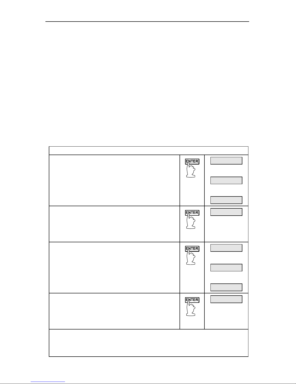
Display maximum and minimum temperatures
Maximum temperature
Press ENTER, the first function displayed is
HI t, press ENTER again to display the
maximum temperature reached by the process
since last reset. Maximum temperature will be
displayed for 3 seconds, then display will show
flashing
CLEAr.
500F
then
HI t
then
725F
Reset maximum temperature
After maximum temperature is displayed, CLEAr
function appears. Press ENTER to reset
maximum temperature in memory or press ACK
to exit without resetting value in memory.
CLEAr
Minimum temperature
Press ENTER when
LO t is displayed to display
minimum temperature reached by the process
since last reset. Minimum temperature will be
displayed for 3 seconds, then display will show
flashing
CLEAr.
500F
then
LO t
then
475F
Reset minimum temperature
After minimum temperature is displayed, CLEAr
function appears. Press ENTER to reset
maximum temperature in memory or press ACK
to exit without resetting value in memory.
CLEAr
• Pressing ENTER while Max/min values are being displayed advances display to
CLEAr.
• Pressing ACK at any time in the above-described operations exits to reading
mode.
Page 42
Large Display Temperature Meters Instruction Manual
42
Relays Operation
Overview
The relay option added to the Digital Temperature Meter expands its usefulness
beyond simple indication to provide users with alarms and simple on/off
temperature controlling functions. There are two basic ways the relays can be
used:
1. High or low alarms with latching or non-latching relay operation.
2. Simple on/off temperature control with 100% adjustable deadband.
Relays Auto Initialization
When power is applied to the meter, the front panel LEDs and alarm relays will
reflect the state of the input to the meter. For instance, if the meter is powered up
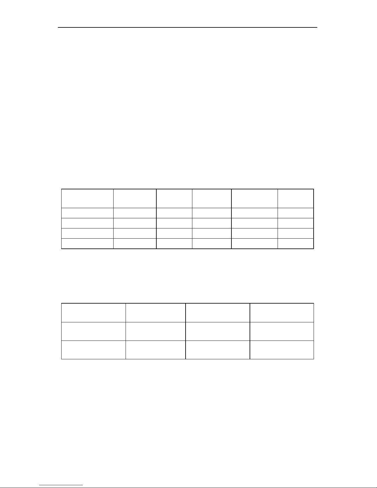
and reads 500, the following table indicates how the alarm LEDs and relays will
react based on the various set and reset points:
Alarm # HI or LO
Set
Point
Reset
Point
Power-Up
Reading
Relay &
LED
1 HI 1000 500 499 Off
2 LO 700 900 500 On
3 LO 250 400 500 Off
4 HI 450 200 500 On
Fail-Safe Operation
The following table indicates how the relays behave based on Jumper J5 being
installed or not installed:
Jumper J5 on
Options PCB
Fail-Safe Relay coils
Energized in
Power Failure
On Enabled Non-alarm state Relays go to
alarm state
Off Disabled Alarm state Relays go to
non-alarm state
Page 43
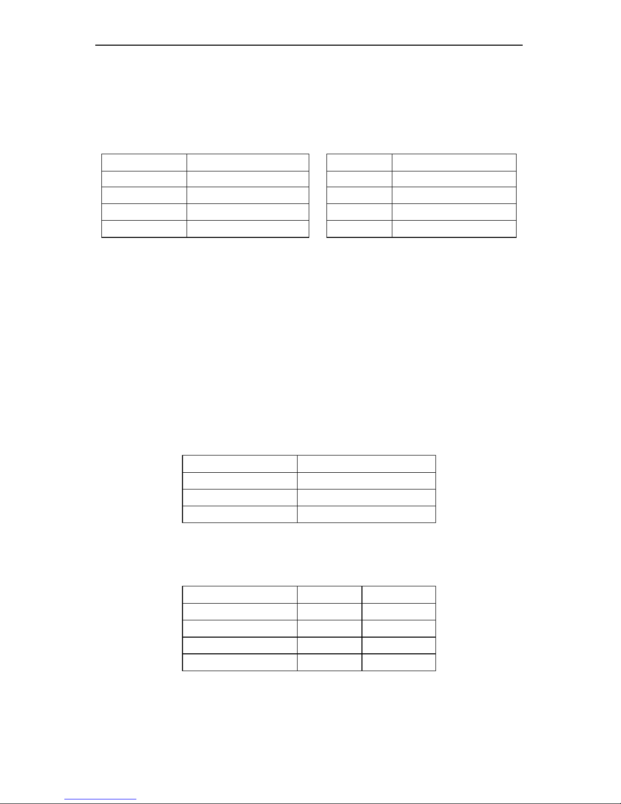
Large Display Temperature Meters Instruction Manual
43
Front Panel LEDs
Refer to Figure 37 on page 65 for PD755.
Refer to Figure 38 on page 65 for PD756.
Refer to Figure 39 on page 65 for PD757.
The LEDs on the front panel provide status for the following:
LED Status LED Status
1 Alarm 1 S Set point indicator
2 Alarm 2 R
Reset point indicator
3 Alarm 3 4 4 mA indicator
4 Alarm 4 20 20 mA indicator
The Digital Temperature Meter is supplied with four alarm points that include front
panel LEDs to indicate alarm conditions. This standard feature is particularly
useful for alarm applications that require visual-only indication. The front panel
LEDs are controlled by the set and reset points programmed by the user and the
acknowledge function in latching relay operation. When the display passes a set
point for a particular alarm, that alarm’s LED will light up. When the meter passes
back through that alarm’s reset point the LED will go off if alarm point was set up
for non-latching operation.
Alarm status LEDs respond differently for latching and non-latching relays.
For non-latching relays, LEDs are always off during normal condition and always
on during alarm condition, regardless of state of the relay.
For latching relays, LEDs reflect state of the relays, regardless of the alarm
condition. The following tables illustrate how the alarm LEDs function in relation
to the relays and the acknowledge button:
Relay key legend for following tables
Key Relay condition
On Tripped
Off Reset
Ack Acknowledged
The On and Off keys do not refer to the status of the relay’s coil, which depends
on the fail-safe mode selected.
Non-Latching Relay
Automatic reset only JP5(1-4 off)
Condition LED Relay
Normal Off Off
Alarm On On
Ack (No effect) On On
Normal Off Off
In this application, the meter is set up for automatic reset and non-latching relay.
Acknowledging the alarm while it is present has no effect on either the LED or the
relay. When the alarm finally goes away, the relay automatically resets and the
LED goes off.
Page 44
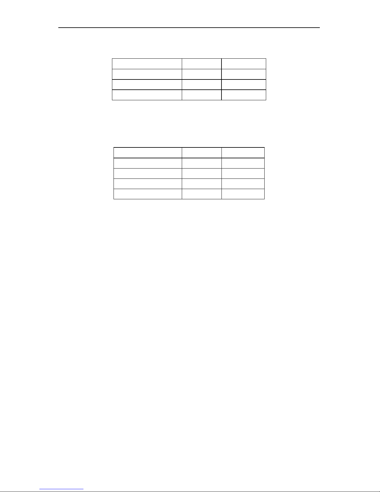
Large Display Temperature Meters Instruction Manual
44
Non-Latching Relay
Automatic + manual reset at any time JP5(1-4 on)
Condition LED Relay
Normal Off Off
Alarm On On
Normal Off Off
In this application, the meter is set up for automatic + manual reset at any time
and non-latching relay. The LED and the relay automatically reset when the
meter returned to the normal condition.
Automatic + manual reset at any time JP5(1-4 on)
Condition LED Relay
Normal Off Off
Alarm On On
Ack On Off
Normal Off Off
In this application, the meter is also set up for automatic + manual reset at any
time. However, this time, an operator acknowledges the alarm manually while it
still exists. This causes the relay to reset, but the LED stays on until the meter
returns to the normal condition. Remember, for non-latching relays, the LED is
always OFF during normal condition and always ON during alarm condition,
regardless of the state of the relay.
Page 45
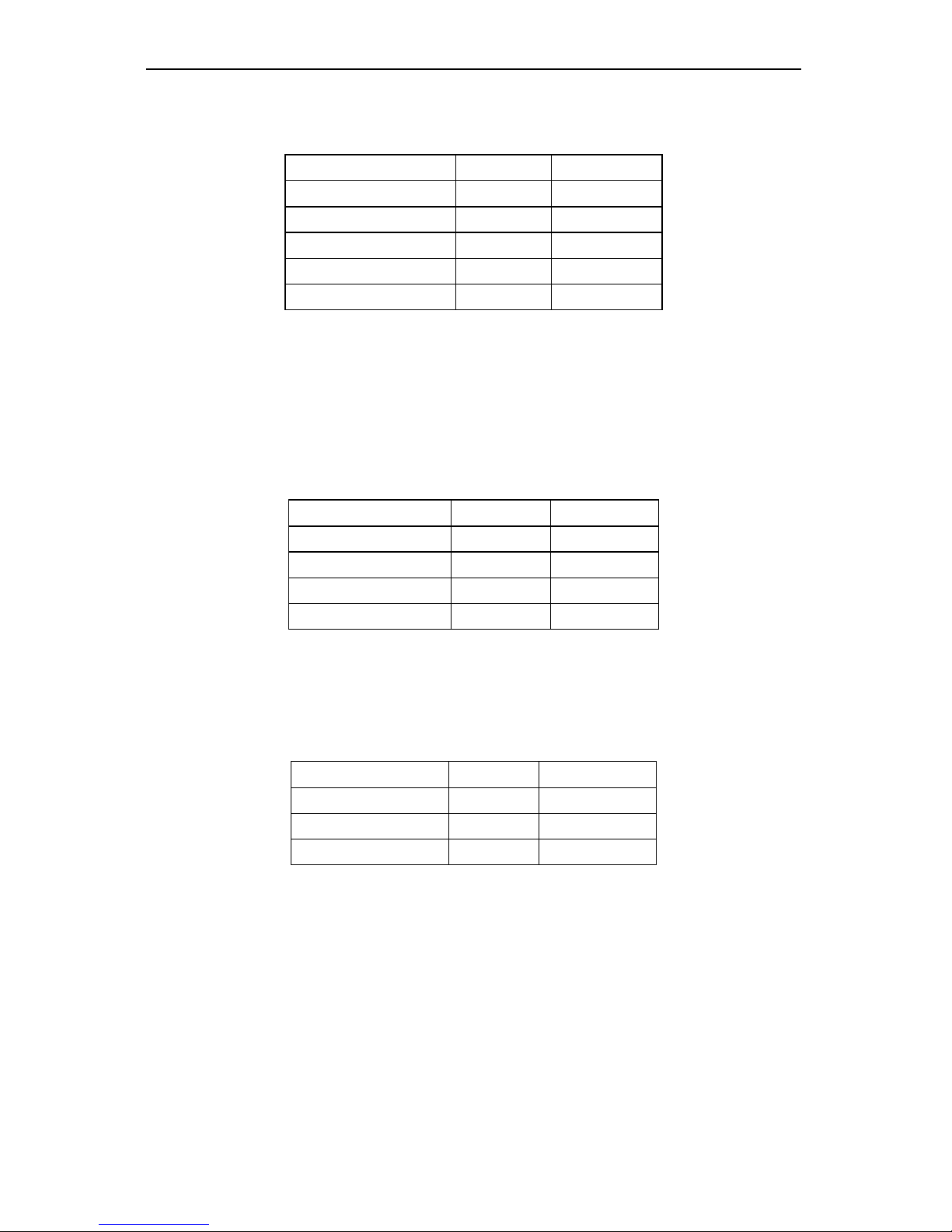
Large Display Temperature Meters Instruction Manual
45
Latching Relay
Manual reset only after signal passes reset point JP5(1-4 off)
Condition LED Relay
Normal Off Off
Alarm On On
Ack (No effect) On On
Normal On On
Ack Off Off
In this application, the meter is set up for manual reset only after the signal
passes the reset point of the latching relay. Acknowledging the alarm while it is
present has no effect on either the LED or the relay. When the alarm is
acknowledged, after it returns to the normal state, the LED and the relay go off.
Notice that the LED remained on; even after the meter returned to the normal
condition. This is because, for latching relays, the alarm LEDs reflect the status
of the relays, regardless of the alarm condition.
Manual reset only after signal passes reset point JP5(1-4 off)
Condition LED Relay
Normal Off Off
Alarm On On
Normal On On
Ack Off Off
In this application, the meter is set up for manual reset only after the signal
passes the reset point of the latching relay. When the alarm is acknowledged,
after it returns to the normal state, the LED and the relay go off.
Latching Relay
Manual reset any time JP5(1-4 on)
Condition LED Relay
Normal Off Off
Alarm On On
Ack Off Off
In this application, the meter is set up for manual reset at any time.
Acknowledging the alarm even if the alarm condition is present resets the relay
and turns off the LED.
Acknowledging Relays
There are two ways to acknowledge relays programmed for manual reset: via the
front panel ACK button and remotely via a switch wired across AK and CM
terminals on the Main PCB. When the ACK button or a switch wired across the
AK and CM terminals is closed, all relays programmed for manual reset will reset.
Page 46
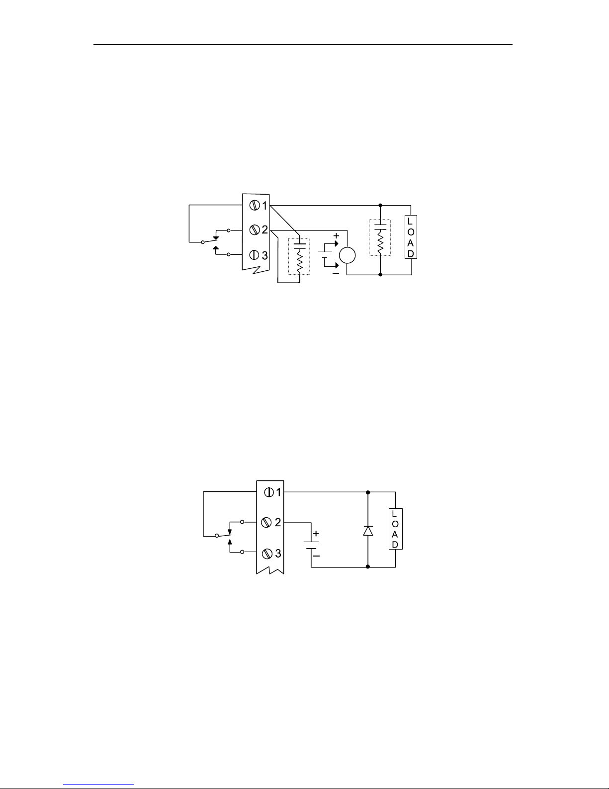
Large Display Temperature Meters Instruction Manual
46
Switching Inductive Loads
The relay contacts on the Options PCB are already protected with suppression
components (snubbers).
If additional suppression is required, this suppression can be obtained with RC
networks assembled by the user or purchased as a complete assembly. Refer to
the following circuits for RC network assembly and installation:
AC and DC Loads
Figure 13. AC and DC Loads Protection
Choose R and C as follows:
R: 0.5 to 1 Ω for each volt across the contacts
C: 0.5 to 1 µF for each 1 A through closed contacts
Notes:
1. Use capacitors rated for 240 VAC.
2. Snubbers may affect load release time of solenoid loads, check to confirm
proper operation.
3. Install the RC network at the Digital Temperature Meter 's relay screw
terminals. An RC network may also be installed across the load, experiment
for best results.
Low Voltage DC Loads
Figure 14. Low Voltage DC Loads Protection
Note: Use a diode with a reverse breakdown voltage two to three times the circuit
voltage and forward current at least as large as the load current.
4-20 mA Output Operation
The Digital Temperature Meter can be equipped with an isolated 4-20 mA output
option that can be programmed to produce a 4-20 mA signal between any two
temperature values.
Page 47
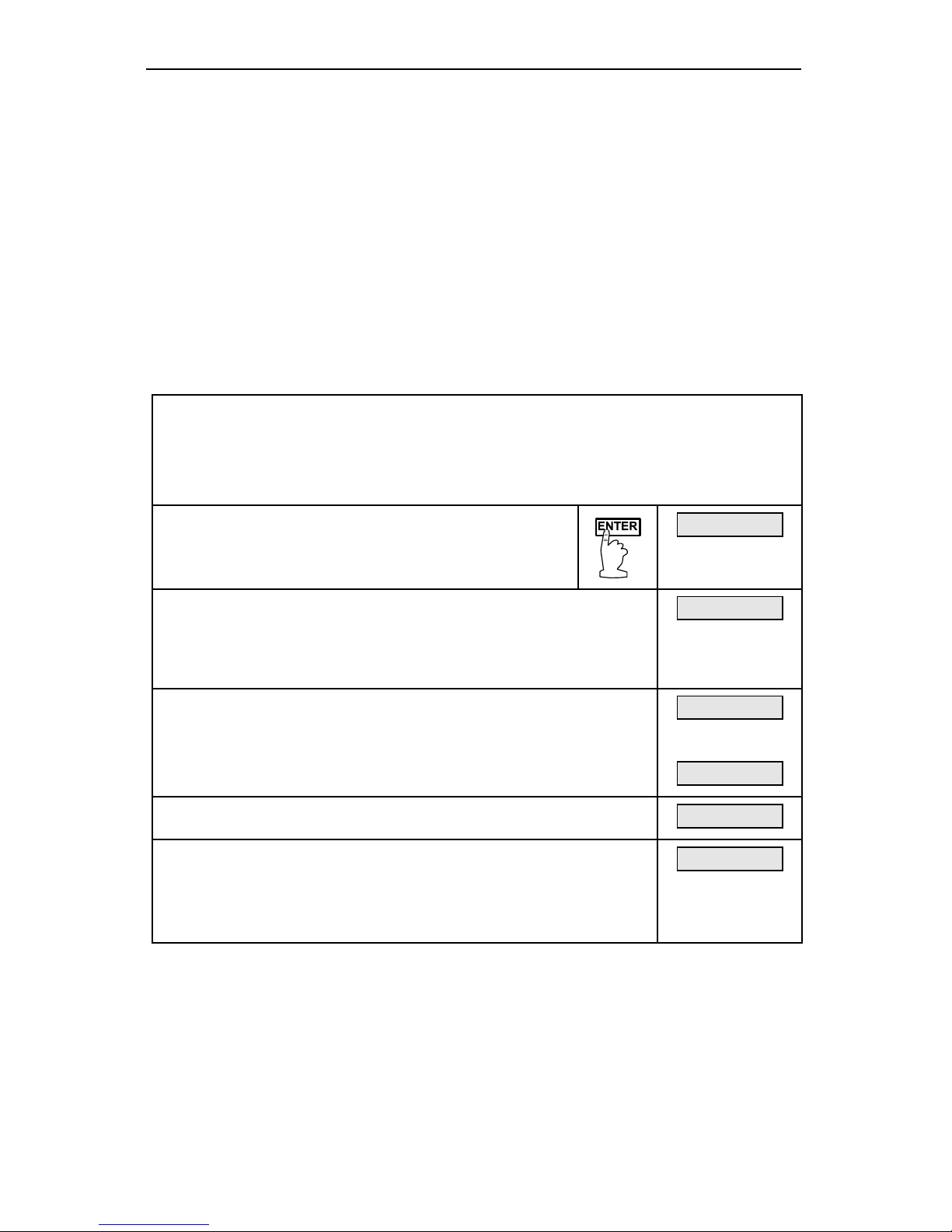
Large Display Temperature Meters Instruction Manual
47
RECALIBRATION (CALIB)
The Digital Temperature Meter is precalibrated for six types of thermocouples
and two types of 100 Ω RTD sensors. These input ranges may be recalibrated
and should be checked every 12 months.
Calibration is performed from the front panel using the ENTER button. The
lockout jumper JP2 must be removed to gain access to the calibration menu, see
Input Selection and Lockout Jumpers (Main PCB), on page 19. The only
equipment needed is a thermocouple calibrator or a 5 decade resistance box with
an accuracy of about 0.1% and a minimum resistance step of 0.01 Ω for RTD
calibration.
Before attempting to calibrate the meter, make sure type selected and input
signal wires are correct. Using the wrong type selection or the wrong T/C wire will
cause inaccurate temperature readings.
Note To simplify programming, write down the desired programming values
prior to attempting to program the meter. The Programmed
Parameter Settings form, located on page 69, provides a convenient
method to record the user settings; it also provides the factory setting
for most of the programmable parameters.
Press ENTER, then press it again when calibrate
(CalIb) function appears.
CalIb
Input 1 (Inpt 1) will flash. Apply the input corresponding to the low
calibration point. Here, in this example calibration points will be
32°F and 1000°F. It is recommended to set the calibration points
outside the minimum and maximum expected temperature readings.
Press ENTER.
Inpt 1
Set the low calibration
For instructions, see
Five Basic Digit/Display-Setting
Instructions on page 31. After
low calibration point has been programmed, the display will flash
Inpt 2.
00000f
final
00032f
Input 2 (Inpt 2) will flash. Apply the input corresponding to the high
calibration point. Press ENTER.
Inpt 2
Set the high calibration point
The procedure used to set the low calibration point is the same for
the high calibration point. In this example we will set it for 1000°F.
After high calibration point has been programmed, display moves to
the next menu function.
1000f
Calibration Error (error)
A meter display of Error during calibration indicates that the calibration process was not
successful. The meter should be recalibrated.
The Error message will appear if input 1 signal and input 2 signal are too close together.
The Error message will appear if input 1 signal is inadvertently applied for input 2
calibration signal, or ENTER is pressed before applying input 2.
In all cases, if an error message appears, previous calibration points will be retained in
memory.
Page 48
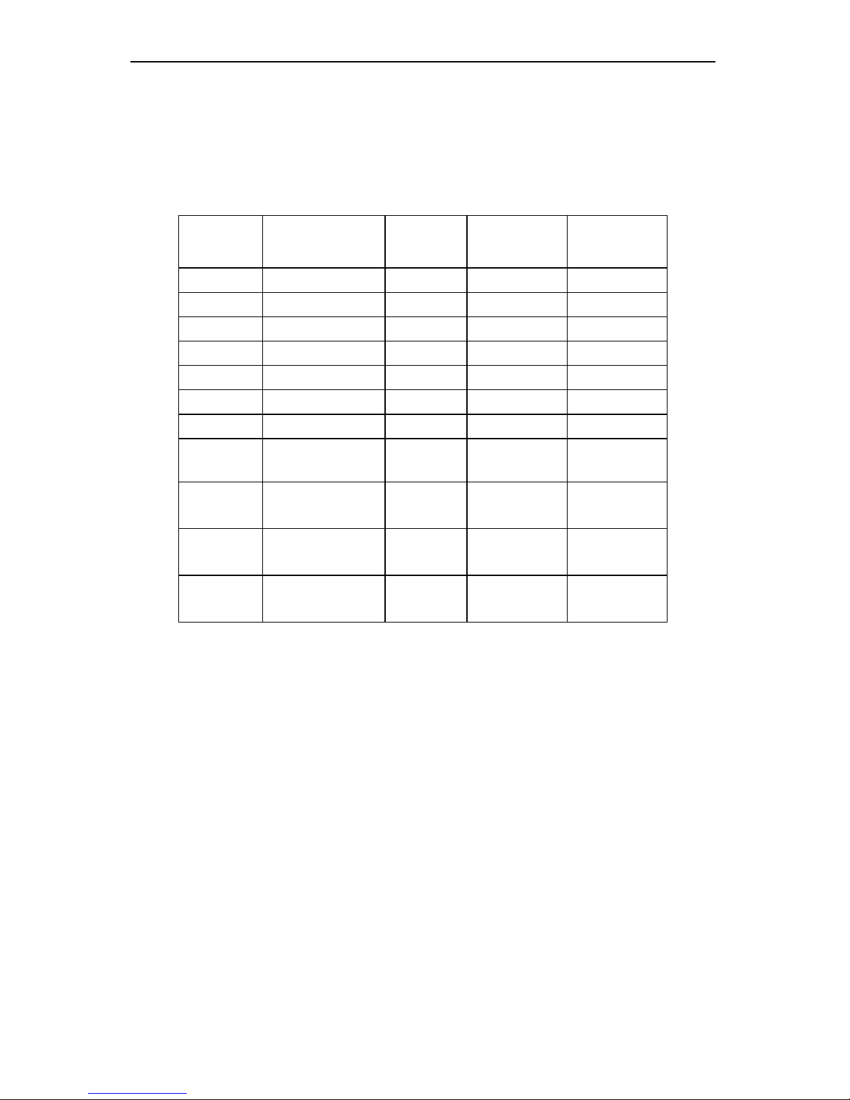
Large Display Temperature Meters Instruction Manual
48
Recommended Calibration Points
To calibrate the meter, it is recommended to use the Fahrenheit scale; this will
give a greater degree of accuracy to the calibration. The scale can be changed to
the Celsius scale after calibration is complete; the meter will display temperature
accurately in any scale. The following table shows the recommended low and
high calibration points for all types.
Type
Number
Type of input Input 1
(Low)
Input 2
(High)
Check
(Middle)
0 Type J T/C
32°F 1182°F 600°F
1 Type K T/C
32°F 1893°F 960°F
2 Type T T/C
32°F 693°F 360°F
3 Type T T/C
32.0°F 693.0°F 360.0°F
4 Type E T/C
32°F 1652°F 840°F
5 Type R T/C
100°F 3000°F 1500°F
6 Type S T/C
100°F 3000°F 1500°F
7
100 Ω RTD
(0.00385, 0.1°)
32.0°F
100Ω
1148.0°F
320.12Ω
590.0°F
215.61Ω
8
100 Ω RTD
(0.00392, 0.1°)
32.0°F
100Ω
1127.0°F
320.89Ω
580.0°F
215.87Ω
9
100 Ω RTD
(0.00385, 1°)
32°F
100Ω
1148°F
320.12Ω
590°F
215.61Ω
10
100 Ω RTD
(0.00392, 1°)
32°F
100Ω
1127°F
320.89Ω
580°F
215.87Ω
Minimum Input Span
Minimum span between input 1 and input 2 signals is 5 mV; consult a
thermocouple table to convert mV to °F or °C for selected T/C type and specific
temperature range. For RTD inputs the minimum input span is 10 Ω . Accuracy
within the calibrated span will be improved, but outside the calibrated span
accuracy will not be reliable.
Calibration Verification
To verify calibration:
• Apply low calibration point signal and note reading.
• Apply high calibration point signal and note reading.
• Apply mid-scale signal and note reading.
Noted readings should be within accuracy specification for selected type.
Otherwise, meter should be recalibrated for selected type and required
temperature span.
Page 49

Large Display Temperature Meters Instruction Manual
49
INSTALLATION
The overall dimensions for the Digital Temperature Meters are shown in:
Figure 40 on page 66 for PD755.
Figure 41 on page 66 for PD756.
Figure 42 on page 67 for PD757.
Wall Mounting Instructions
PD755 Mounting
There are four mounting holes on the base of the enclosure. They are used to
mount the instrument to a wall. The dimensions for the mounting holes are shown
in Figure 43 on page 67.
Procedure:
1. Drill holes into the wall to accommodate suitable fasteners.
2. Remove the front bezel from the housing by removing the four mounting
screws.
3. Align the enclosure mounting holes with the holes in the wall and insert the
fasteners. Tighten the fasteners (see the screw mounting in Figure 44 on
page 67).
PD756 Mounting
There are four mounting holes on the base of the enclosure. They are used to
mount the instrument to a wall. The dimensions for the mounting holes are shown
in Figure 45 on page 68.
Procedure:
1. Drill holes into the wall to accommodate the fasteners.
2. Align the enclosure mounting holes with the holes in the wall and insert the
fasteners. Tighten the fasteners.
PD757 Mounting
There are four mounting holes on the rear of the enclosure. They are used to
mount the instrument to a wall. The dimensions for the mounting holes are shown
in Figure 46 on page 68.
Procedure:
1. Drill holes into the wall to accommodate suitable fasteners.
2. Remove the front bezel from the housing by removing the four mounting
screws.
3. Align the enclosure mounting holes with the holes in the wall and insert the
fasteners. Tighten the fasteners.
Page 50
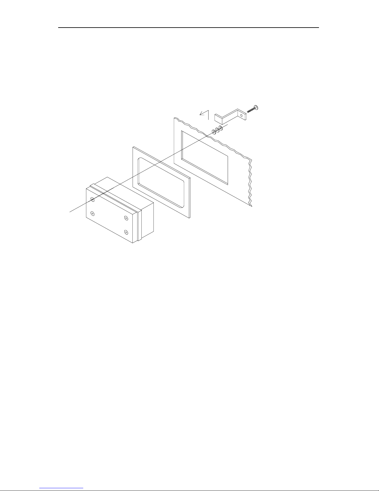
Large Display Temperature Meters Instruction Manual
50
Panel Mounting Instructions
For applications where it is required to mount the Digital Temperature Meter into
a panel, panel mounting kits are available for PD755 and PD757.
(See Ordering Information on page 7)
PD755 Panel Mounting Instructions
1
2
MOUNTING PLATE
PANEL
(4) MTG. BRACKETS
3
(4) SELF TAPPING
S
C
R
E
W
S
SEE NOTES
(12) WASHERS
PANEL OPENING
Figure 15. PD755 Panel Mounting
Instructions:
1. Insert the meter through the mounting plate.
2. Mount assembly on panel.
3. Secure with 4 brackets and 4 screws at corners of the meter.
4. Use washers as needed to allow for panel thickness.
Notes:
1. Allowable panel thickness: 0.060" – 0.125" (1.5 mm – 3.2 mm)
2. Panel cutout required: 6.62" x 5.43" (168 mm x 138 mm)
3. Mounting plate overall dimensions: 7.57" x 6.40" x 0.125"
(192 mm x 163 mm x 3 mm)
4. Mounting brackets require 0.8" (20 mm) on either top or side of meter for
installation.
5. This panel mounting kit is not intended to provide waterproof protection to
the panel.
Page 51
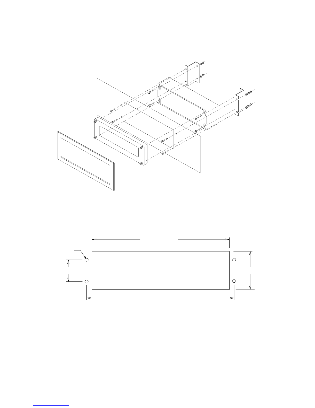
Large Display Temperature Meters Instruction Manual
51
PD757 Panel Mounting Instructions
DECORATIVE BEZEL
METER COVER
PANEL
METER BASE
BRACKET
Figure 16. PD757 Panel Mounting
14.30" (363)
4.97" (126)
15.32" (389)
3.23" (82)
Ø0.250"
(6.4)
Figure 17. PD757 Panel Mounting Cutout Dimensions
Page 52

Large Display Temperature Meters Instruction Manual
52
Parts Supplied with Panel Mounting Kit:
1. Two angle brackets
2. One self-adhesive decorative bezel
3. Eight #12-24 x ¾" screws
4. Eight #12 lock washers
5. Eight #12-24 hex nuts
6. Four #12 flat washers
Panel Mounting Assembly Instructions:
1. Drill four holes in panel and make panel cutout as shown. Tolerance for all
dimensions is ±0.01" (0.25 mm).
2. Secure the two side mounting brackets to the meter base using the supplied
hardware.
3. Mount this assembly to the rear of the panel using supplied hardware.
4. Secure the meter cover to the base.
5. Attach decorative bezel to the panel.
Notes:
1. Allowable panel thickness: 0.06" – 0.25" (1.5 mm x 6.4 mm). Longer bracket
screws may be used for panel thickness up to 0.5" (12.7 mm).
2. Mounting space required: 7" x 17.5" x 4" (178 mm x 445 mm x102 mm)
(H x W x D). Meter cover extends 0.8" (20 mm) - X from the surface of the
panel, where X equals the thickness of the panel.
3. This panel mounting kit is not intended to provide waterproof protection to
the panel.
4. All dimensions are in inches and millimeters ( ).
Page 53
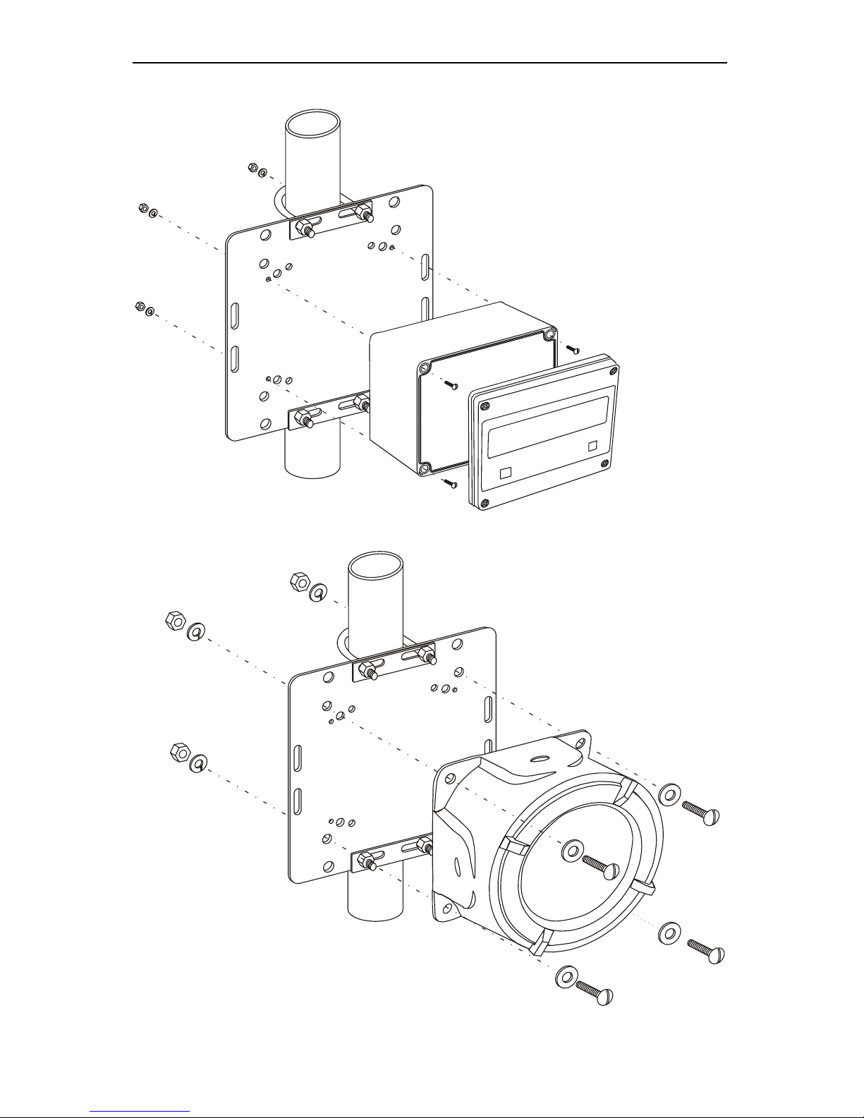
Large Display Temperature Meters Instruction Manual
53
Pipe Mounting Instructions for PD755 and PD756
Figure 18. 755 Pipe Mounting Assembly
Figure 19. 756 Pipe Mounting Assembly
Page 54

Large Display Temperature Meters Instruction Manual
54
Figure 20. Pipe Mounting Plate
Parts Supplied:
1. One mounting plate
2. Two 2" U-bolt kits
3. Four 5/16–18 x 1¼ " screws
4. Four 5/16–18 hex nuts
5. Four 5/16 flat washers
6. Four 5/16 split washers
7. Four 6-32 x ¾" screws
8. Four 6-32 hex nuts
9. Four 6-32 split washers
HARDWARE USAGE TABLE
(Refer to Parts Supplied above)
1. 2. 3. 4. 5. 6. 7. 8. 9.
Model Hole
PD755 A X X X X X
PD756 B X X X X X X
Page 55
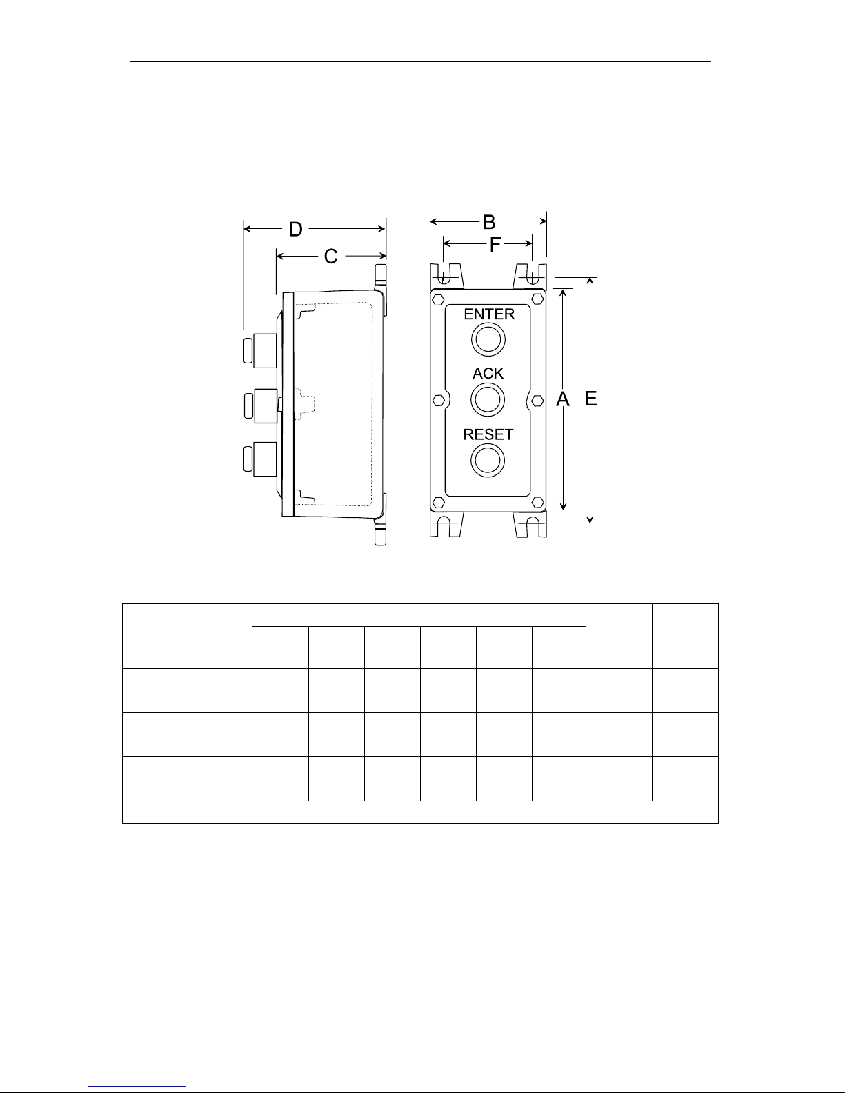
Large Display Temperature Meters Instruction Manual
55
Explosion-Proof Control Stations
The explosion-proof control stations can be used to control the PD756 while in
operation in a hazardous area. Control stations may be ordered with one, two, or
three push buttons. The buttons can be labeled ENTER, ACK, and RESET.
External connections are available at J1 connector on the main PCB.
Figure 21. Explosion-proof Control Station
Dimensions in Inches and mm( )
Number of
Switches
A B C D E F
Wt
lbs
(kg)
Std.
Cond.
Size
1
4.5
(114)
4.5
(114)
4.19
(106)
6.19
(157)
5.5
(140)
3.25
(83)
4.5
(2.0)
¾"
2
7.0
(178)
4.5
(114)
4.19
(106)
6.19
(157)
8.0
(203)
3.25
(83)
6.0
(2.7)
¾"
3
8.0
(203)
4.5
(114)
4.19
(106)
6.19
(157)
9.0
(229)
3.25
(83)
6.75
(3.1)
¾"
Note: Control Stations have conduit openings centered on top and bottom.
Page 56
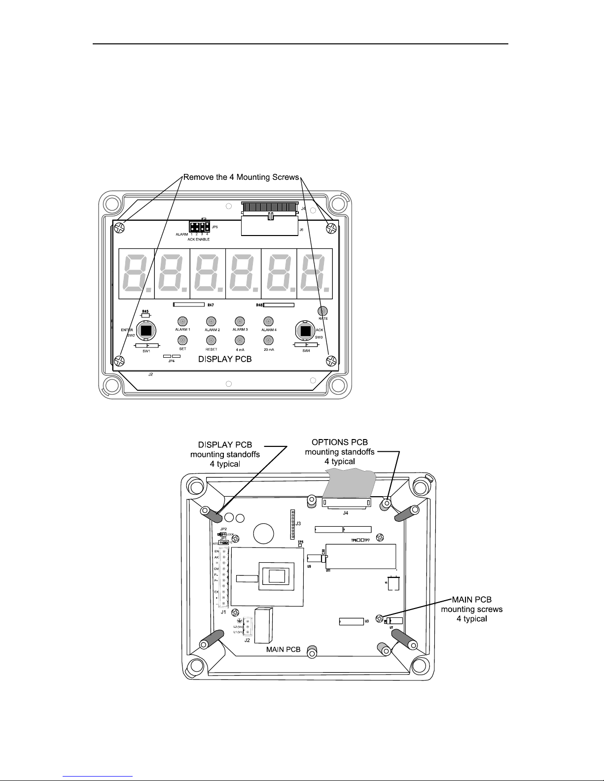
Large Display Temperature Meters Instruction Manual
56
OPTION CARD REMOVAL & INSTALLATION
Meter options are installed at the factory. To disable relays’ fail-safe operation, it
is necessary to remove the Display PCB to gain access to the Options PCB.
Option cards may be ordered separately. Refer to the following instructions and
illustrations.
Option Card Installation in PD755
Figure 22. Removing the PD755 Display PCB
Figure 23. PD755 Options PCB Standoffs Location
Page 57
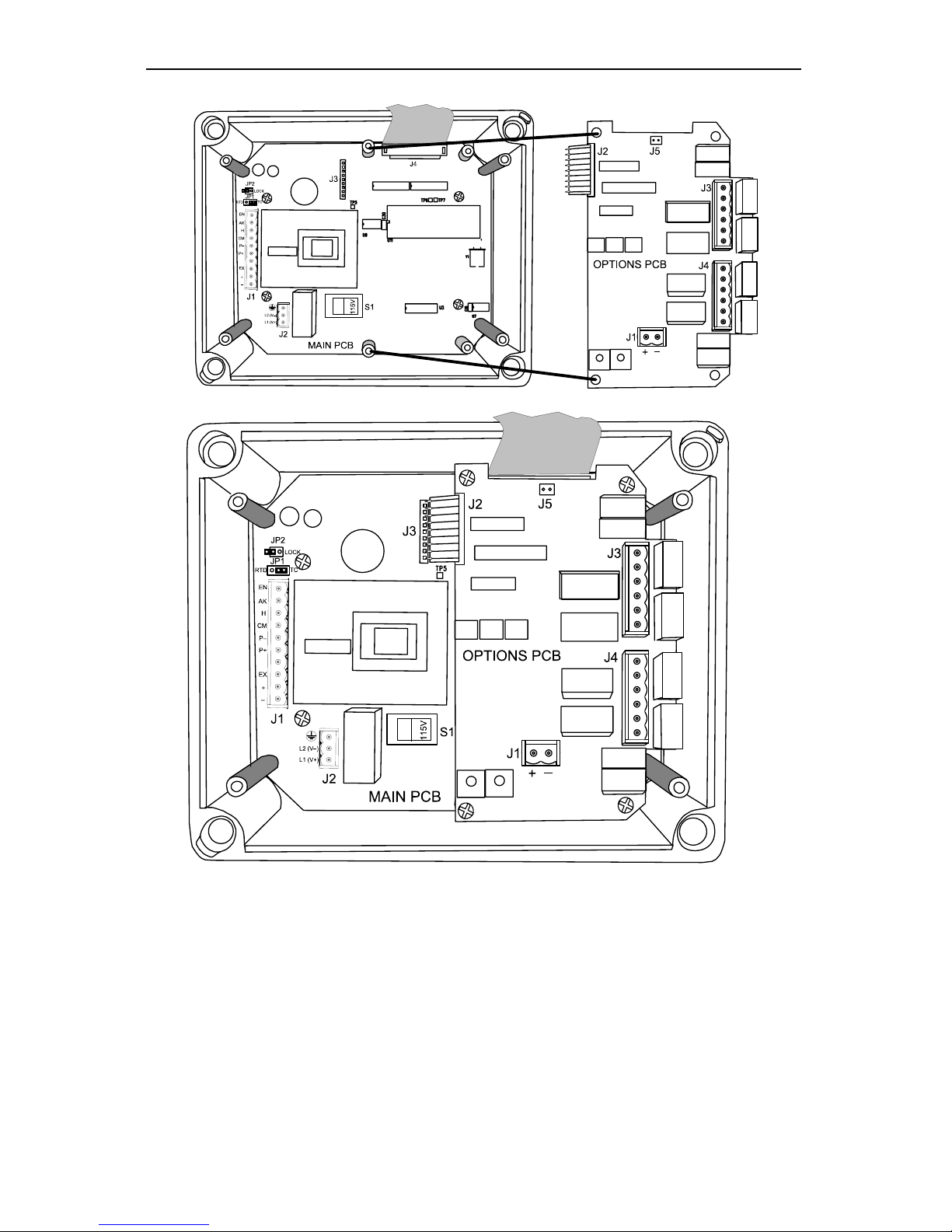
Large Display Temperature Meters Instruction Manual
57
Figure 24. PD755 Options PCB Installation
Instructions:
1. Disconnect power to the meter prior to removing the front cover.
2. Remove Display PCB and detach PCB from ribbon cable connector.
3. Remove Main PCB from the base by removing four mounting screws.
4. Install Options PCB standoffs, using provided hex nuts.
5. Connect flexible cable connector J2 to J3 connector on Main PCB.
6. Install 4 mounting screws to secure Options PCB to standoffs.
7. Reassemble meter prior to applying power. Front cover may remain off until
programming is completed to allow installation of lockout jumper (see Figure
31, page 61).
Page 58
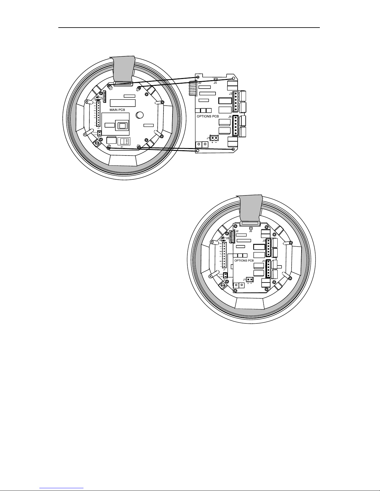
Large Display Temperature Meters Instruction Manual
58
Option Card Installation in PD756
To install the Options PCB into PD756, refer to the following figures.
Figure 25. PD756 Option PCB Installation
Figure 26. PD756 Option PCB Installed
Instructions:
1. Disconnect power to the meter prior to removing the front cover.
2. Remove Display PCB and detach PCB from ribbon cable connector. Display
PCB may be removed without removing the faceplate.
3. Remove Main PCB from the base by removing four mounting screws.
4. Install Options PCB standoffs, using provided hex nuts.
5. Connect flexible cable connector J2 to J3 connector on Main PCB.
6. Install 4 mounting screws to secure Options PCB to standoffs.
7. Reassemble meter prior to applying power. Front cover may remain off until
programming is completed to allow installation of lockout jumper (see Figure
32, page 62).
Page 59
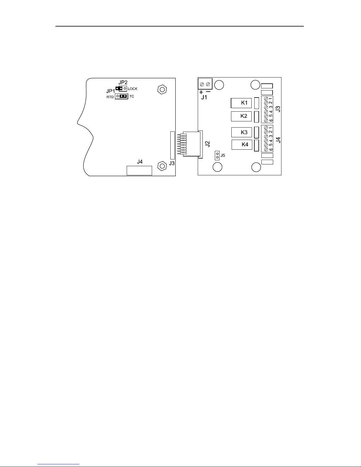
Large Display Temperature Meters Instruction Manual
59
Option Card Installation in PD757
To install the Options PCB into PD757, refer to the following figure.
Main PCB Options PCB
Figure 27. PD757 Option PCB Installation
Instructions:
1. Disconnect power to the meter prior to removing the front cover.
2. Remove Display PCB and detach PCB from ribbon cable connector.
3. Remove two right-side standoffs and plastic washers; discard plastic
washers.
4. Install Options PCB, using the two standoffs removed in step 3.
5. Connect flexible cable connector J2 to J3 connector on Main PCB.
6. Reassemble meter prior to applying power. Front cover may remain off until
programming is complete to allow access to ENTER and ACK buttons as
well as installation of lockout jumper (see Figure 36, page 64).
Page 60
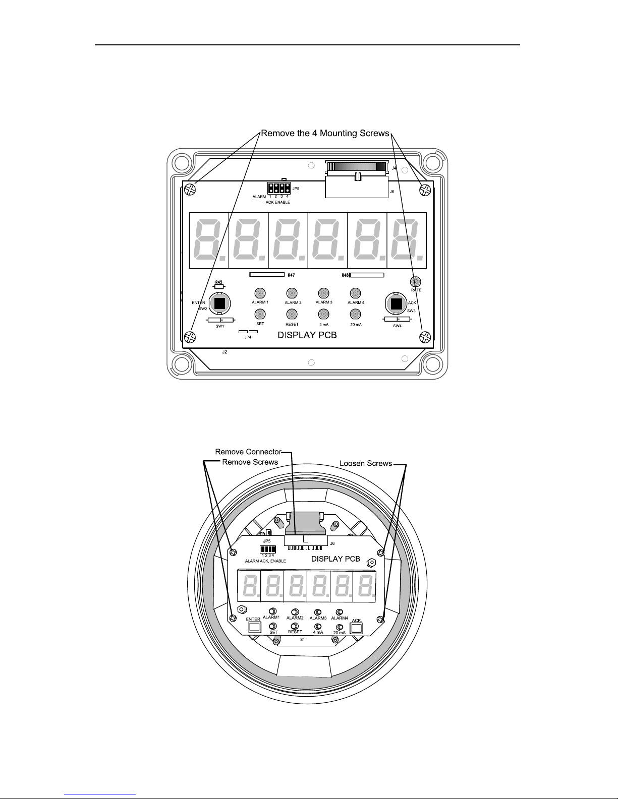
Large Display Temperature Meters Instruction Manual
60
MODEL SENSITIVE ILLUSTRATIONS
Removing the Display PCB
Figure 28. Removing the Display PCB on PD755
Figure 29. Removing the Display PCB on PD756
Page 61
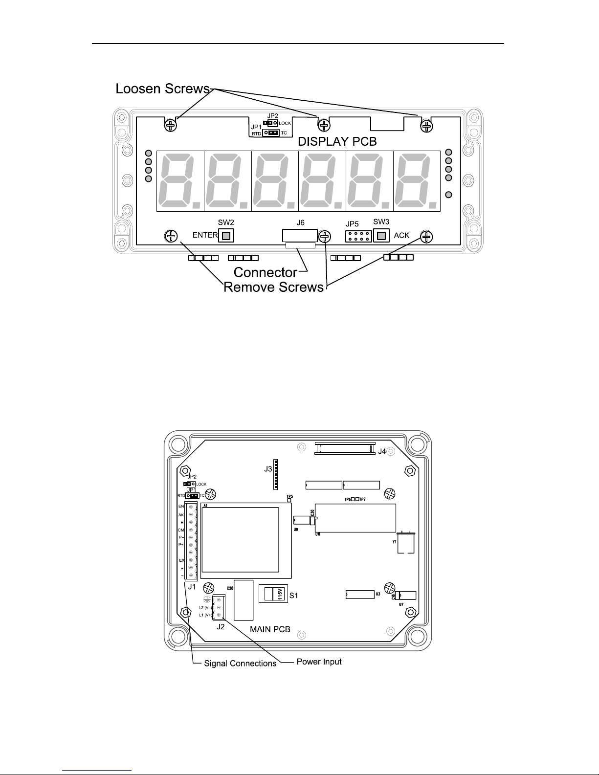
Large Display Temperature Meters Instruction Manual
61
Figure 30. Removing the Display PCB on PD757
Locations of Connections and Jumpers
Figure 31. PD755 Connectors and Jumper Location
Page 62
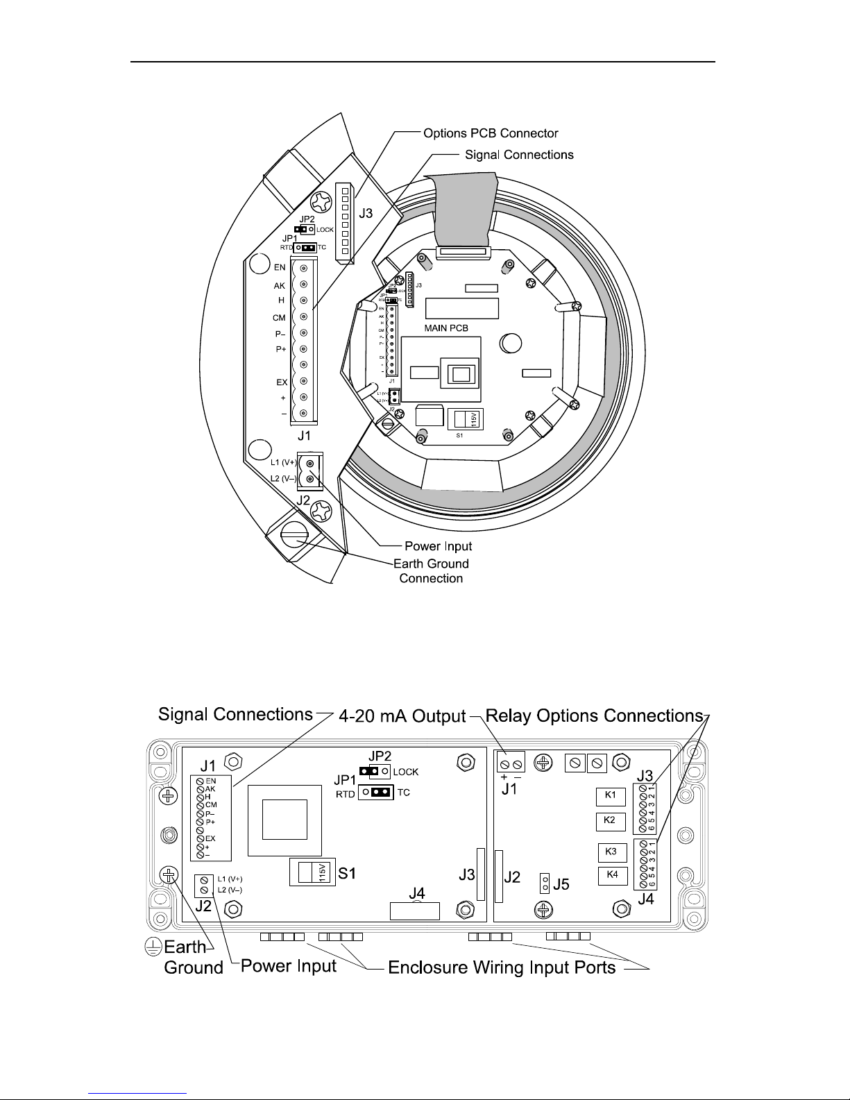
Large Display Temperature Meters Instruction Manual
62
Figure 32. PD756 Connectors and Jumper Location
OPTIONS PCBMAIN PCB
Figure 33. PD757 Connectors and Jumper Location
Page 63
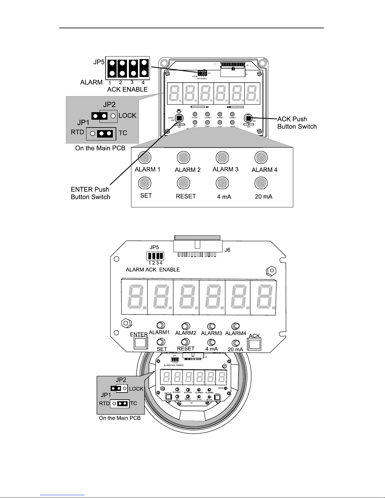
Large Display Temperature Meters Instruction Manual
63
Jumper Arrays and Status LEDs
Figure 34. PD755 Jumper Arrays and Status LED Identification
Figure 35. PD756 Jumper Arrays and Status LED Identification
Page 64
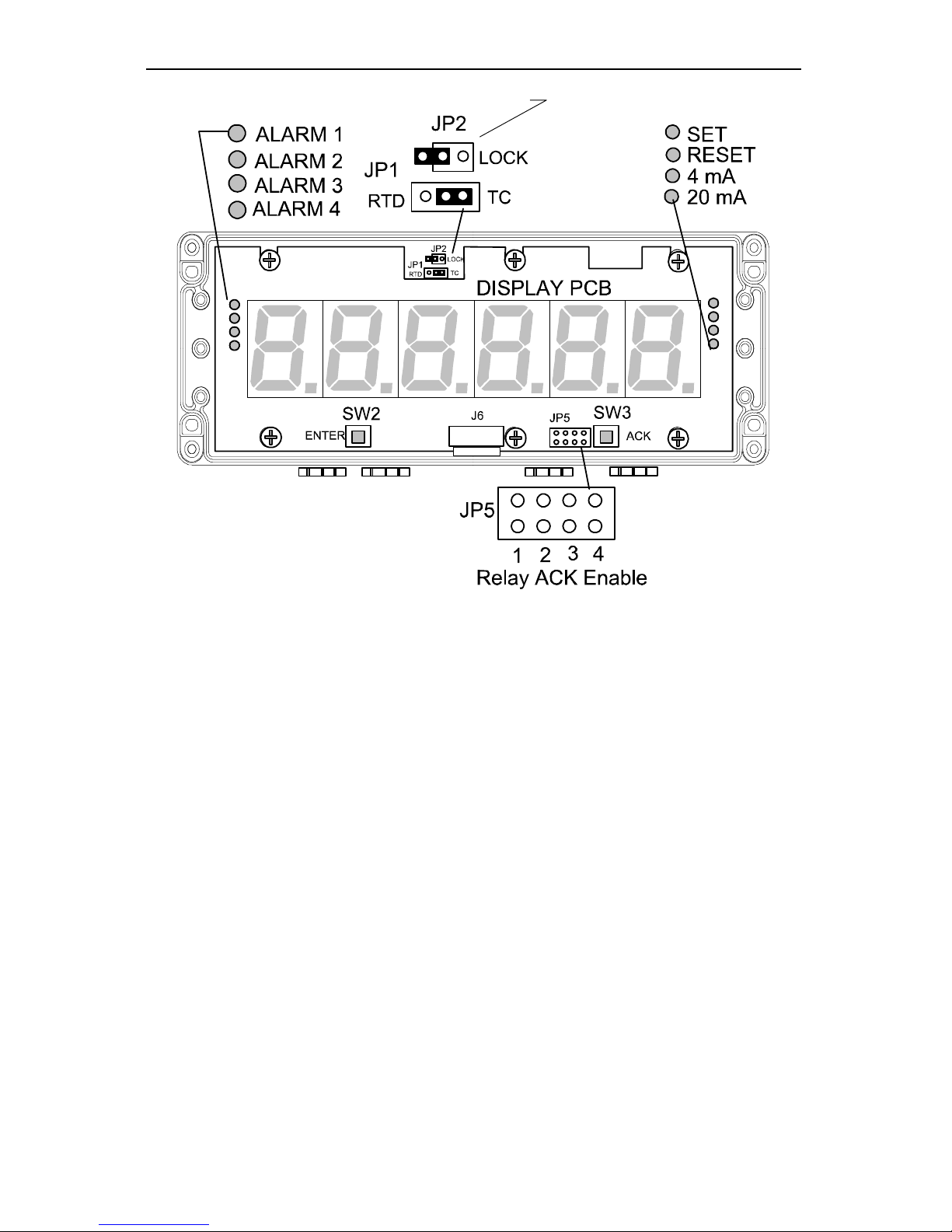
Large Display Temperature Meters Instruction Manual
64
On the bottom PCB
Figure 36. PD757 Jumper Arrays and Status LED Identification
Page 65
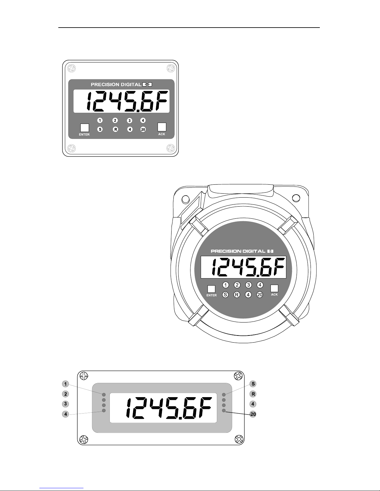
Large Display Temperature Meters Instruction Manual
65
Front Panel Displays
Figure 37. PD755 Front Panel Display
Figure 38. PD756 Front Panel Display
Figure 39. PD757 Front Panel Display
Page 66
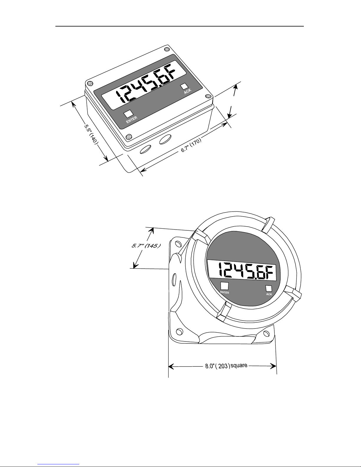
Large Display Temperature Meters Instruction Manual
66
Overall Dimensions
3.7" (95)
Figure 40. PD755 Overall Dimensions
Figure 41. PD756 Overall Dimensions
Page 67
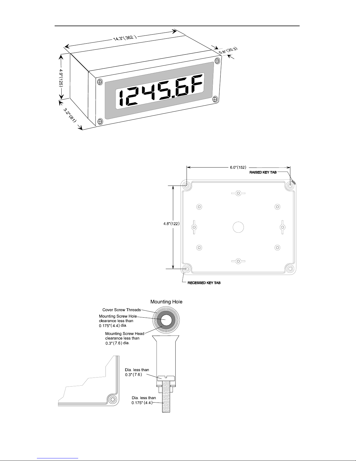
Large Display Temperature Meters Instruction Manual
67
Figure 42. PD757 Overall Dimensions
Wall Mounting Dimensions
Figure 43. PD755 Wall Mounting Dimensions
Figure 44. PD755 Wall Mounting Screw Installation
Page 68
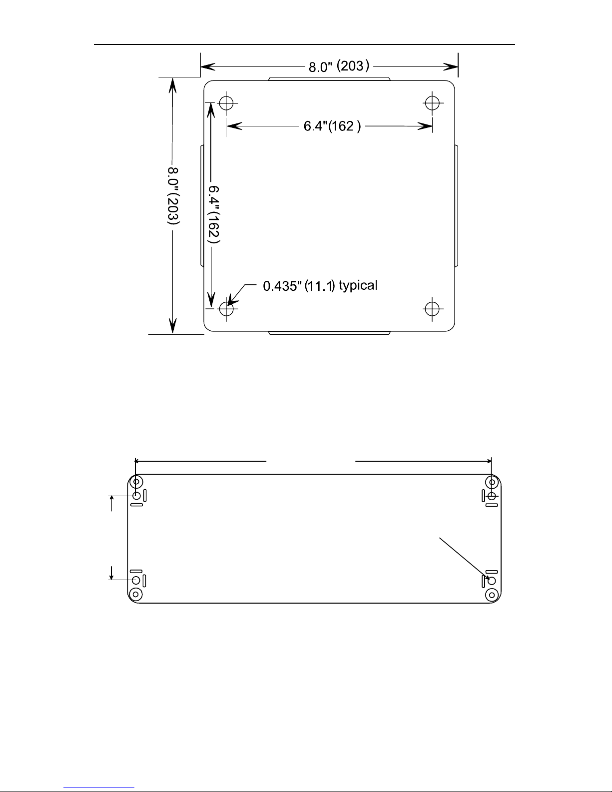
Large Display Temperature Meters Instruction Manual
68
Figure 45. PD756 Wall Mounting Dimensions
13.49" (342.6)
13.54" (344.0)
0.25" (6.2) dia. typ.
3.2" (82)
Figure 46. PD757 Wall Mounting Dimensions
Page 69

Large Display Temperature Meters Instruction Manual
69
PROGRAMMED PARAMETER SETTINGS
The following table shows the factory setting for most of the programmable
parameters on the Digital Temperature Meter. Next to the factory setting, the
user may record the new setting for the particular application.
Model: ______________ S/N: _______________ Date: _________
Parameter Display Factory Setting User Setting
Input type
type
J T/C
(
type 0 )
Input Offset
Offset
00000F
Temperature
Scale
F or C
Fahrenheit ( f )
Alarm Points
Setup
setup
Non-latching
(Automatic reset)
set 1
latCH
n (No)
set 2
latCH
n (No)
set 3
latCH
n (No)
set 4
latCH
n (No)
Alarms set
points
setpts
Alarm 1
set 1
Set
00100f
Reset
00050f
Alarm 2
set 2
Set
00200f
Reset
00150f
Alarm 3
set 3
Set
00300f
Reset
00250f
Alarm 4
set 4
Set
00400f
Reset
00350f
Output
output
4 mA
000.00f
20 mA
100.00f
Page 70
Large Display Temperature Meters Instruction Manual
70
OTHER PRECISION DIGITAL PRODUCTS
Model Description
PD118 MINIMUX® Eight Point Scanner
PD128 PLC Annunciator
PD128-NI PLC Annunciator (FM & CSA Approved)
PD141AFO VIGILANTE® four Point Annunciator with First-Out
PD148 AC/DC Input Annunciator (UL Listed)
PD602 DART Low-Cost 1/8 DIN Process Meter
PD650 2.3" LED NEMA 4X Large Display Process Meter
PD655 1.0" LED NEMA 4X Large Display Process Meter
PD656 0.8" LED Exp-Proof Large Display Process Meter
PD660 Low-Cost NEMA 4X Loop Powered Meter
PD661 Low-Cost Exp-Proof Loop Powered Meter
PD673/674 4½ Digit Loop Powered 1/8 DIN Meter
PD675/676 4½ Digit Loop Powered NEMA 4X Meter (FM & CSA)
PD677/678 4½ Digit Loop Powered Exp-Proof Meter
PD680 3½ Digit Loop Powered 1/8 DIN Meter
PD682 3½ Digit Loop Powered 1/8 DIN Meter (FM Approved)
PD686 3½ Digit Loop Powered NEMA 4X Meter (FM & CSA)
PD687 3½ Digit Loop Powered Exp-Proof Meter
PD690 1/8 DIN Universal Process Meter (UL Listed)
PD691 1/8 DIN Universal Strain Gauge Meter (UL Listed)
PD692 1/8 DIN Analog Input Flow Totalizer (UL Listed)
PD693 1/8 DIN Freq/Pulse Input Flow Totalizer (UL Listed)
PD694 1/8 DIN 0-200 VDC Volt Meter (UL Listed)
PD695 1/8 DIN True RMS AC Volt Meter
PD696 1/8 DIN Loop Powered Flow Rate/Totalizer
PD697 NEMA 4X Loop Powered Flow Rate/Totalizer
PD698 Exp-Proof Loop Powered Flow Rate/Totalizer
PD750 1/8 DIN Universal Temperature Meter (UL Listed)
PD765 TRIDENT Process & Temperature Meter
Page 71

Large Display Temperature Meters Instruction Manual
71
NOTES
Page 72

Large Display Temperature Meters Instruction Manual
LIM755-7_C.doc
SFT002 Ver 1.300 & up
03/03
www.predig.com
How to Contact Precision Digital
• For Technical Support please
call: (800) 610-5239
fax: (508) 655-8990
e-mail: [email protected]
• For Sales Support or to place an order please
call: (800) 343-1001
fax: (508) 655-8990
e-mail: [email protected]
• For Warranty Registration and to Double Your
Warranty on-line please visit
www.predig.com
• For an online version of this instruction manual
please visit
www.predig.com
 Loading...