

Page 1
PRECISION DIGITAL CORPORATION
233 South Street • Hopkinton MA 01748 USA
Tel (800) 343-1001 • Fax (508) 655-8990
www.predig.com
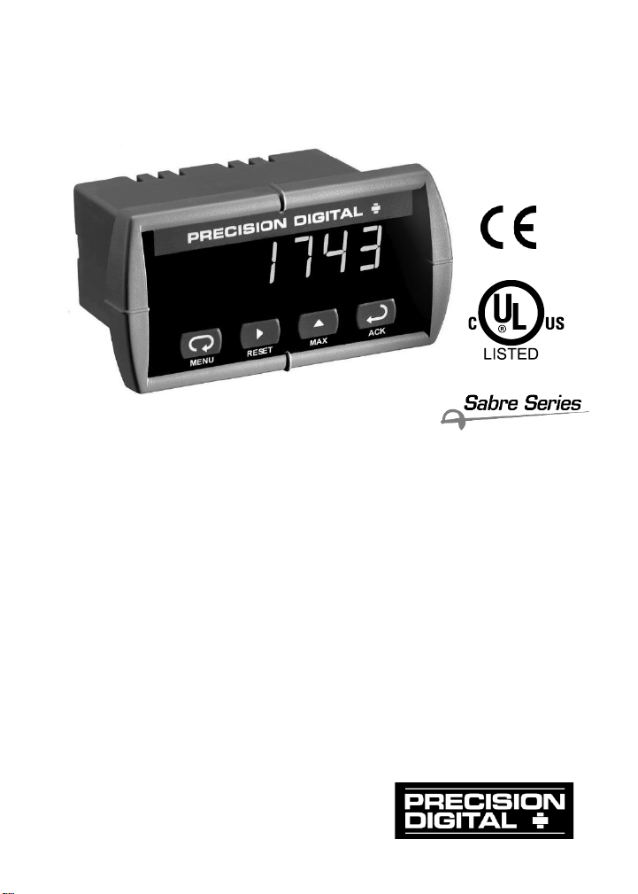
SABRE T MODEL PD743
TEMPERATURE METER
Instruction Manual
• J, K, T, E Thermocouple & 100 Pt RTD
• Pre-Calibrated for All Input Types
• Type 4X, NEMA 4X, IP65 Front
• Shallow Depth Case 3.2" Behind Panel
• 4 Digit Display, 0.56" (14 mm) High, Red LEDs
• Easy Front Panel Programming
• Maximum/Minimum Display
• Universal Power Supply 85-265 VAC
• 12-36 VDC/12-24 VAC Power Option
Page 2
Sabre T Model PD743 Temperature Meter Instruction Manual
2
Disclaimer
The information contained in this document is subject to change
without notice. Precision Digital makes no representations or warranties with respect to the contents hereof, and specifically disclaims
any implied warranties of merchantability or fitness for a particular
purpose.
© 2022 Precision Digital Corporation. All rights reserved.
INTRODUCTION
The Sabre T model PD743 is an easy-to-use temperature meter. It accepts
type J, K, T, E thermocouple and 100 platinum RTD sensors. The four
front panel buttons make the setup and programming an easy task.
ORDERING INFORMATION
85-265 VAC*
Model
12-36 VDC*
Model
Description
PD743-6R0-0
PD743-7R0-0
Temperature Meter
*All models may be powered from AC or DC, see Specifications for details.
NEMA 4 & NEMA 4X Enclosures
Model
# of
Meters
Description
Mounting
PDA2500
1 - 6
Plastic NEMA 4X Enclosure
Through Door
PDA2600
1 - 6
Stainless Steel NEMA 4X Enclosure
Through Door
PDA2700
1 - 6
Steel NEMA 4 Enclosure
Through Door
PDA2801
1
Plastic NEMA 4X Enclosure
Through Cover
Page 3

Sabre T Model PD743 Temperature Meter Instruction Manual
3
Table of Contents
INTRODUCTION ------------------------------------------------------------ 2
ORDERING INFORMATION --------------------------------------------- 2
SPECIFICATIONS ---------------------------------------------------------- 5
General ------------------------------------------------------------------------------- 5
Temperature Inputs -------------------------------------------------------------- 6
COMPLIANCE INFORMATION ----------------------------------------- 7
Safety --------------------------------------------------------------------------------- 7
Electromagnetic Compatibility ----------------------------------------------- 7
EU DECLARATION OF CONFORMITY ------------------------------ 8
SAFETY INFORMATION ------------------------------------------------- 8
INSTALLATION ------------------------------------------------------------- 9
Unpacking --------------------------------------------------------------------------- 9
Panel Mounting -------------------------------------------------------------------- 9
Connections ---------------------------------------------------------------------- 10
Connector Labeling ---------------------------------------------------------- 10
Power Connections ---------------------------------------------------------- 10
Signal Connections ---------------------------------------------------------- 11
SETUP AND PROGRAMMING ---------------------------------------- 14
Front Panel Buttons and Status LED Indicators --------------------- 15
Display Functions and Messages ----------------------------------------- 16
Main Menu ------------------------------------------------------------------------ 17
Setting Numeric Values ------------------------------------------------------ 18
Setting Up the Meter (setu) ------------------------------------------------- 18
Setting the Input Signal (inpt) -------------------------------------------- 19
Setting the Temperature Scale (F C) ---------------------------------- 20
Programming the Meter (prog) --------------------------------------------- 21
Recalibrating Temperature Inputs (Cal) -------------------------------- 21
Setting Up the Password (pass) ------------------------------------------- 24
Locking the Meter ------------------------------------------------------------ 24
Unlocking the Meter ---------------------------------------------------------- 24
OPERATION ---------------------------------------------------------------- 26
Front Panel Buttons Operation -------------------------------------------- 26
Maximum/Minimum Readings ---------------------------------------------- 27
MOUNTING DIMENSIONS ---------------------------------------------- 28
Page 4

Sabre T Model PD743 Temperature Meter Instruction Manual
4
TROUBLESHOOTING ---------------------------------------------------- 29
Troubleshooting Tips --------------------------------------------------------- 29
QUICK USER INTERFACE REFERENCE GUIDE ---------------- 30
Table of Figures
Figure 1. Panel Cutout and Mounting ................................................. 9
Figure 2. Connector Labeling ............................................................ 10
Figure 3. Power Connections ............................................................ 10
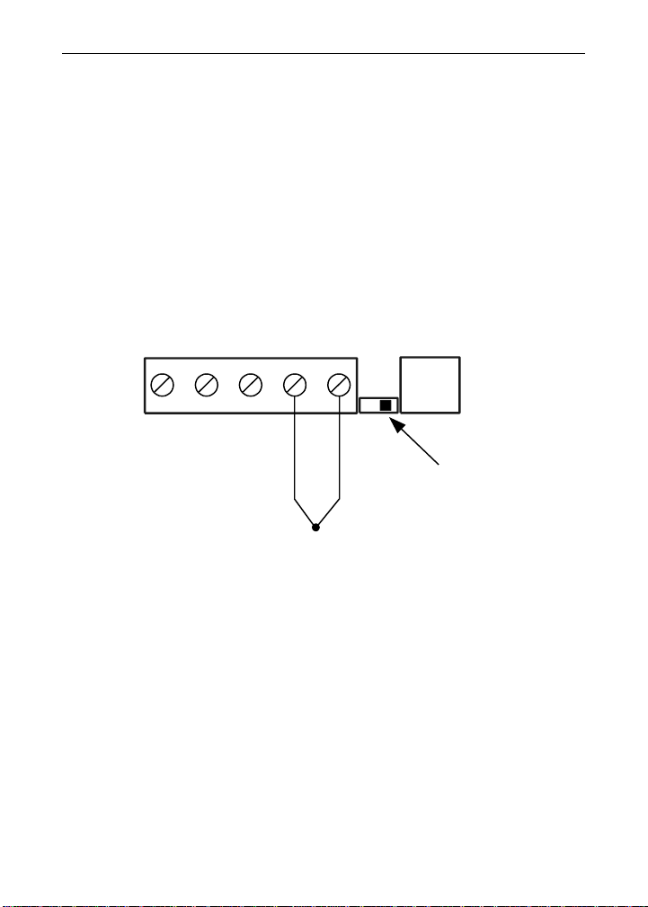
Figure 4. Thermocouple Input Connections .................................... 11
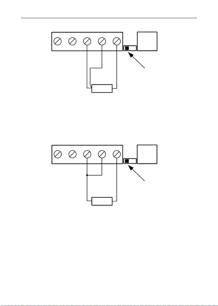
Figure 5. Three-Wire RTD Input Connections .................................. 12
Figure 6. Two-Wire RTD Input Connections ................................ ..... 12
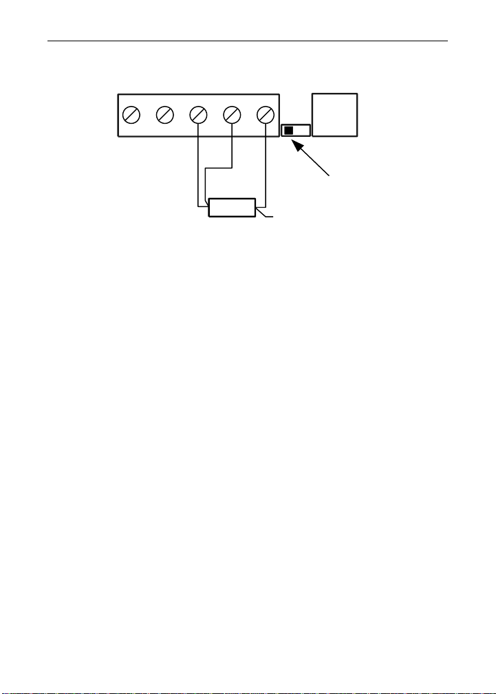
Figure 7. Four-Wire RTD Input Connections .................................... 13
Figure 8. Meter Dimensions - Side View ........................................... 28
Figure 9. Case Dimensions - Top View ............................................. 28
Page 5
Sabre T Model PD743 Temperature Meter Instruction Manual
5
SPECIFICATIONS
Except where noted all specifications apply to operation at +25°C.
General
DISPLAY
0.56" (14 mm) high, red LED
Four digits, automatic lead zero blanking.
DISPLAY
UPDATE RATE
RTD: 5/second
Thermocouple: 2.5/second
OVERRANGE
Display flashes 9999
UNDERRANGE
Display flashes -1999
PROGRAMMING
METHODS
Four front panel buttons
RECALIBRATION
All ranges are calibrated at the factory. Recalibration is
recommended at least every 12 months.
MAX/MIN
DISPLAY
Max/min readings reached by the process are stored until
reset by the user or until power to the meter is turned off.
PASSWORD
Programmable password restricts modification of
programmed settings.
NON-VOLATILE
MEMORY
All programmed settings are stored in non-volatile memory
for a minimum of ten years if power is lost.
POWER
OPTIONS
85-265 VAC, 50/60 Hz; 90-265 VDC, 8 W max
or 12-36 VDC, 12-24 VAC, 6 W max
FUSE
Required fuse: UL Recognized, 5 A max, slow blow
Up to 6 meters may share one 5 A fuse
NORMAL MODE
REJECTION
64 dB at 50/60 Hz
ISOLATION
4 kV input-to-power line
OVERVOLTAGE
CATEGORY
Installation Overvoltage Category II:
Local level with smaller transient overvoltages than Installation Overvoltage Category III.
ENVIRONMENTAL
Operating temperature range: 0 to 65°C
Storage temperature range: -40 to 85°C
Relative humidity: 0 to 90% non-condensing
CONNECTIONS
Removable screw terminal blocks accept 12 to 22 AWG
wire, RJ11 for factory use only.
ENCLOSURE
1/8 DIN, high impact plastic, UL 94V-0, color: gray
MOUNTING
1/8 DIN panel cutout required. Two panel mounting
bracket assemblies provided
Page 6
Sabre T Model PD743 Temperature Meter Instruction Manual
6
TIGHTENING
TORQUE
Screw terminal connectors: 5 lb-in (0.56 Nm)
OVERALL
DIMENSIONS
2.45" x 4.68" x 3.79" (62 mm x 119 mm x 96 mm)
(H x W x D)
WEIGHT
8.5 oz (241 g)
WARRANTY
1 year parts & labor
EXTENDED
WARRANTY
1 or 2 years, refer to the Price List for details.
Temperature Inputs
INPUTS
Field selectable: Type J, K, T, or E thermocouples;
100 platinum RTD (0.00385 or 0.00392 curve)
RESOLUTION
1 for all thermocouples and RTD inputs
1 or 0.1 for Type T thermocouple
ACCURACY
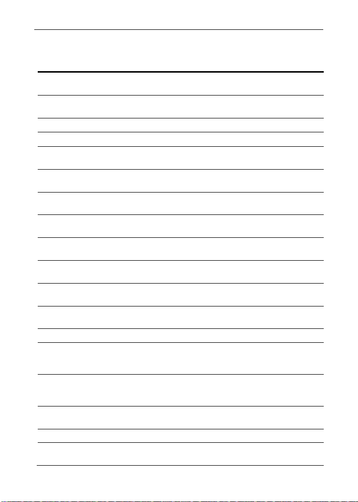
Input Type
Range
Accuracy
Type J
-58 to 1382 F
-50 to 750C
2F
1C
Type K
-58 to 2300 F
-50 to 1260C
2F
1C
Type T
-292 to 700 F
-180 to 371C
2F
1C
Type T
0.1 Res
-199.9 to 700.0 F
-180.0 to 371.0C
1.8F
1.0C
Type E
-58 to 1700 F
-50 to 927C
2F
1C
100 RTD
-328 to 1382F
-200 to 750C
1F
1C
COLD
JUNCTION
REFERENCE
Automatic, fixed, no user calibration needed
TEMPERATURE
DRIFT
2C maximum
0 to 65C ambient temperature
INPUT
IMPEDANCE
Greater than 100 k
Page 7
Sabre T Model PD743 Temperature Meter Instruction Manual
7
COMPLIANCE INFORMATION
Safety
UL LISTED
USA and Canada
UL 508 Industrial Control Equipment
UL FILE NUMBER
E160849
FRONT PANEL
UL Type 4X, NEMA 4X, IP65; panel gasket provided
LOW VOLTAGE
DIRECTIVE
EN 61010-1
Safety requirements for measurement, control, and
laboratory use
Electromagnetic Compatibility
EMISSIONS
EN 55011
Group 1 Class A ISM emissions requirements
Radiated
Emissions
Class A
AC Mains Conducted Emissions
Class A
IMMUNITY
EN 61326-1
Measurement, control, and laboratory equipment
EN 61000-6-2
EMC heavy industrial generic immunity standard
RFI - Amplitude
Modulated
80 -1000 MHz 10 V/m 80% AM (1 kHz)
1.4 - 2.0 GHz 3 V/m 80% AM (1 kHz)
2.0 - 2.7 GHz 1 V/m 80% AM (1 kHz)
Electrical Fast
Transients
±2kV AC mains, ±1kV other
Electrostatic
Discharge
±4kV contact, ±8kV air
RFI - Conducted
10V, 0.15-80 MHz, 1kHz 80% AM
AC Surge
±2kV Common, ±1kV Differential
Surge
1KV (CM)
Power-Frequency
Magnetic Field
30 A/m 70%V for 0.5 period
Voltage Dips
40%V for 5 & 50 periods
70%V for 25 periods
Voltage
Interruptions
<5%V for 250 periods
Page 8
Sabre T Model PD743 Temperature Meter Instruction Manual
8
Note:
Testing was conducted on PD743 meters installed through the covers of grounded metal enclosures with cable shields grounded at
the point of entry representing installations designed to optimize
EMC performance.
EU DECLARATION OF CONFORMITY
EU Declaration of Conformity is available in the Documentation CD
provided with the product under the EU DoC menu.
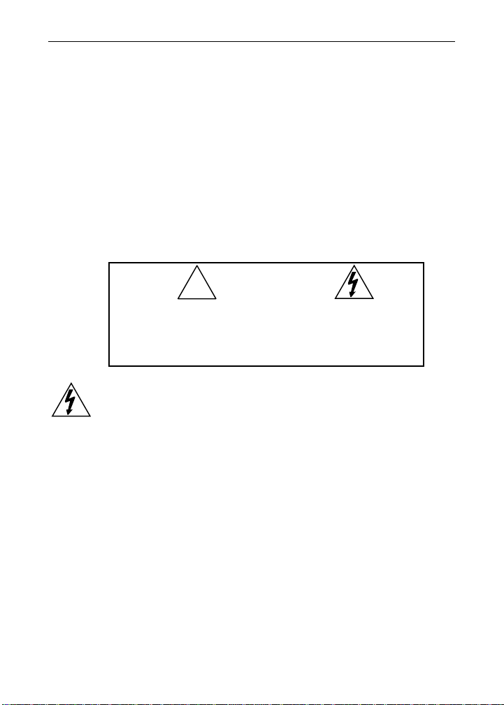
SAFETY INFORMATION
CAUTION: Read complete
instructions prior to installation and operation of the
meter.
WARNING: Risk of
electric shock.
WARNING
Hazardous voltages exist within enclosure. Installation and service
should be performed only by trained service personnel.
!
Page 9
Sabre T Model PD743 Temperature Meter Instruction Manual
9
INSTALLATION
There is no need to remove the meter from its case to complete the
installation, wiring, and setup of the meter.
Unpacking
Remove the meter from box. Inspect the packaging and contents
for damage. Report damages, if any, to the carrier.
If any part is missing or the meter malfunctions, please contact your
supplier or the factory for assistance.
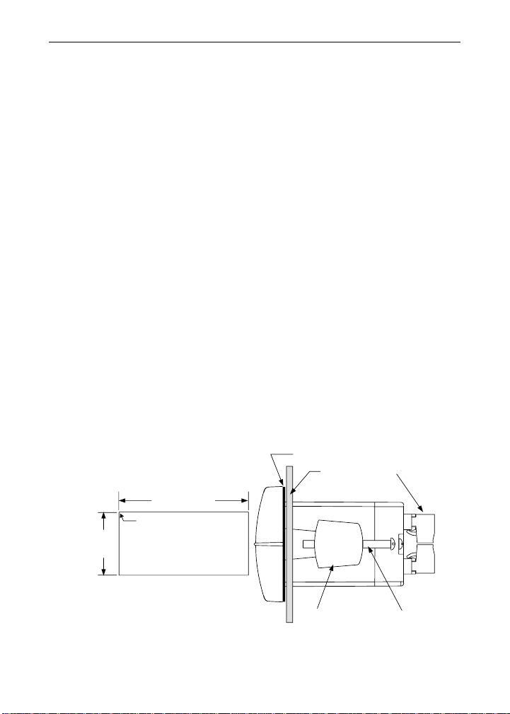
Panel Mounting
• Prepare a standard 1/8 DIN panel cutout – 3.622" x 1.772" (92 mm
x 45 mm). Refer to Mounting Dimensions, page 28 for more details.
• Clearance: allow at least 4" (102 mm) behind the panel for wiring.
• Panel thickness: 0.04" - 0.25" (1.0 mm - 6.4 mm).
Recommended minimum panel thickness to maintain Type 4X
rating: 0.06" (1.5 mm) steel panel, 0.16" (4.1 mm) plastic panel.
• Remove the two mounting brackets provided with the meter (back-off
the two screws so that there is ¼" (6.4 mm) or less through the
bracket. Slide the bracket toward the front of the case and remove).
• Insert meter into the panel cutout.
• Install mounting brackets and tighten the screws against the panel.
To achieve a proper seal, tighten the mounting bracket screws
evenly until meter is snug to the panel along its short side. DO NOT
OVER TIGHTEN, as the rear of the panel may be damaged.
Figure 1. Panel Cutout and Mounting
Panel
Gasket
Mounting
Bracket
Mounting
Screw
Removable
Connectors
3.622" (92mm)
1.772"
(45mm)
Panel Cutout
to DIN 43700
Square Corners to 0.060"
(1.5mm) Max Radius
A
B
Tolerances:
A: +0.032 (+0.8mm)
-0.000 (-0.0mm)
B: +0.024 (+0.6mm)
-0.000 (-0.0mm)
Page 10
Sabre T Model PD743 Temperature Meter Instruction Manual
10
Connections
All connections are made to removable screw terminal connectors
located at the rear of the meter.
Use copper wire with 60°C or 60/75°C insulation
for all line voltage connections. Observe all safety
regulations. Electrical wiring should be performed
in accordance with all applicable national, state,
and local codes to prevent damage to the meter
and ensure personnel safety.
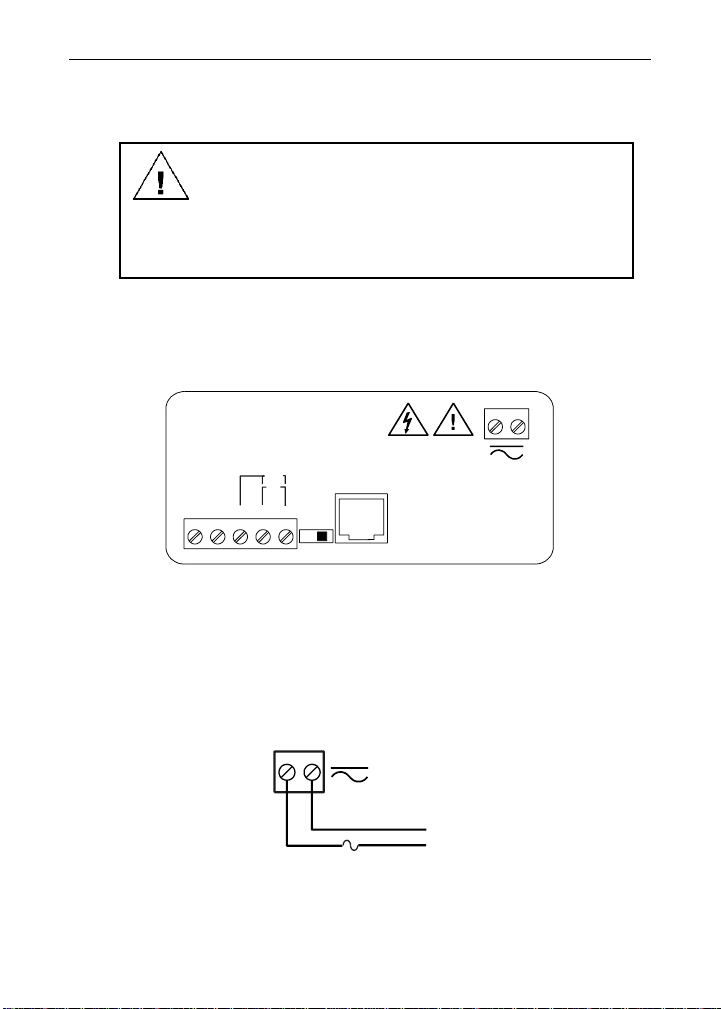
Connector Labeling
The connectors label, affixed to the meter, shows the location of the
connectors. It also identifies the location of the RTD/TC selector switch.
Figure 2. Connector Labeling
Power Connections
Power connections are made to a two-terminal connector labeled
POWER on Figure 2. The meter will operate regardless of DC polarity
connection. The + and - symbols are only a suggested wiring convention.
Figure 3. Power Connections
DW1912
POWER
EXC T+X X COM
Factory
Use
Only
3 41 2 5
2 1
+
-
SIGNAL
RTD TC
SWITCH
TC
RTD
12
AC or DC
POWER
Required External Fuse:
5 A max, Slow Blow
POWER CONNECTOR
+ -
Page 11
Sabre T Model PD743 Temperature Meter Instruction Manual
11
Signal Connections
Signal connections are made to a five-terminal connector labeled
SIGNAL on Figure 2. The COM (common) terminal is the return for all
types of input signals.
Thermocouple and RTD Connections
The following figures show examples for thermocouple and RTD connections.
The RTD/TC selector switch must be set to the proper position for the
meter to accept the selected temperature input.
The input type is selected using the Setup menu.
The selected thermocouple input must correspond to thermocouple sen-
sor and wire type used.
Figure 4. Thermocouple Input Connections
X = No connection
SIGNAL CONNECTOR
21 3 54
-
+
TC
RTD TC
COMXX T+EXC
Switch
Position
Factory
Use Only
Page 12
Sabre T Model PD743 Temperature Meter Instruction Manual
12
Figure 5. Three-Wire RTD Input Connections
The meter accepts two, three, or four-wire RTDs. The three-wire RTD
connection has built-in lead wire compensation.
Figure 6. Two-Wire RTD Input Connections
21 3 54
RTD TC
COMX
X T+
EXC
Switch
Position
RTD
Sensor
Factory
Use Only
SIGNAL CONNECTOR
SIGNAL CONNECTOR
21 3 54
RTD TC
COMXX T+EXC
Switch
Position
RTD
Sensor
Factory
Use Only
Page 13
Sabre T Model PD743 Temperature Meter Instruction Manual
13
Figure 7. Four-Wire RTD Input Connections
The four-wire RTD connection is similar to the three-wire. One of the
leads of a four-wire RTD is not connected, and may be clipped off.
The three-wire connection provides sufficient lead wire compensation to
provide accurate readings even with long leads.
SIGNAL CONNECTOR
21 3 54
RTD TC
COMXX T+EXC
Switch
Position
RTD
Sensor
NC
Factory
Use Only
Page 14

Sabre T Model PD743 Temperature Meter Instruction Manual
14
SETUP AND PROGRAMMING
• There is no need to recalibrate the meter
when first received from the factory.
• The meter is factory calibrated prior to ship-
ment, for all input types, in degrees Fahrenheit. The calibration equipment is certified to
NIST standards.
Overview
There are no jumpers involved in the setup process of the meter. The
RTD/TC selector switch, located between the SIGNAL and RJ11 connectors, must be set accordingly for the meter to accept RTD or thermocouple inputs, Figure 2.
Setup and programming is done through the front panel buttons.
After power and signal connections have been completed and verified,
apply power to the meter.
For
Quick User Interface Reference Guide
go to page 30
Page 15
Sabre T Model PD743 Temperature Meter Instruction Manual
15
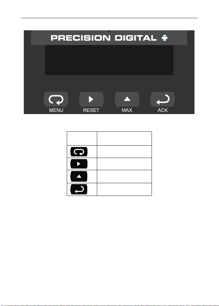
Front Panel Buttons and Status LED Indicators
Button
Symbol
Description
Menu
Right arrow/Reset
Up arrow/Max
Enter/Ack
• Press the Menu button to enter or exit the Programming Mode at
any time.
• Press the Right arrow button to move to the next digit during digit
programming.
• Press the Up arrow button to scroll through the menus, decimal
point, or to increment the value of a digit.
• Press the Enter/Ack button to access a menu or to accept a setting.
1743
Page 16

Sabre T Model PD743 Temperature Meter Instruction Manual
16
Display Functions and Messages
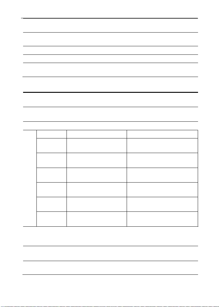
The meter displays various functions and messages during setup/programming and operation. The following table shows the displayed functions and messages with their action/setting description.
Display
Parameter
Action/Setting
setu
Setup
Enter Setup menu
inpt
Input
Enter Input menu
rtd
RTD
Set meter for RTD input
a385
Alpha 385
Set = 0.00385 European curve 100 RTD
A392
Alpha 392
Set = 0.00392 American curve 100 RTD
tC
TC
Set meter for TC input
0 J
0 J
Type J
1 k
1 K
Type K
2 T
2 T
Type T
3 t.0
3 T.0
Type T, 0.1 resolution
4 E
4 E
Type E
f C
F or C
Set temperature scale
F
F
Set meter to Fahrenheit
C
C
Set meter to Celsius
prog
Program
Enter the Program menu
Cal
Calibrate
Enter the Calibrate menu
inp1
Input 1
Calibrate input 1 signal
dis1
Display 1
Program display 1 value
inp2
Input 2
Calibrate input 2 signal
dis2
Display 2
Program display 2 value
err
Error
Error, calibration not successful, check signal
pass
Password
Enter the Password menu
unlC
Unlocked
Program password to lock meter
loCd
Locked
Enter password to unlock meter
9999
-1999
open
Flashing display
Overrange condition
Underrange condition
Open TC or RTD sensor
Page 17
Sabre T Model PD743 Temperature Meter Instruction Manual
17
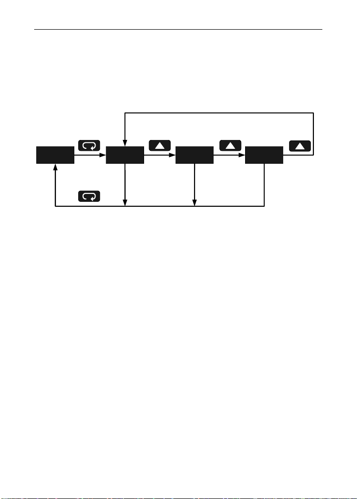
Main Menu
The main menu consists of the following functions: Setup, Program, and
Password.
• Press Menu button to enter Programming Mode then press Up ar-
row button to scroll main menu.
• Press Menu, at any time, to exit and return to Run Mode. Changes
made to settings prior to pressing Enter/Ack are not saved.
• Changes to the settings are saved to memory only after pressing
Enter/Ack.
• The display moves to the next menu every time a setting is ac-
cepted by pressing Enter/Ack.
1743 setu prog pass
Run
Mode
Page 18
Sabre T Model PD743 Temperature Meter Instruction Manual
18
Setting Numeric Values
The numeric values are set using the Right and Up arrow buttons.
Press Right arrow to select next digit and Up arrow to increment digit
value.
The digit being changed is displayed brighter than the rest.
Press the Enter/Ack button, at any time, to accept a setting or Menu
button to exit without saving changes.
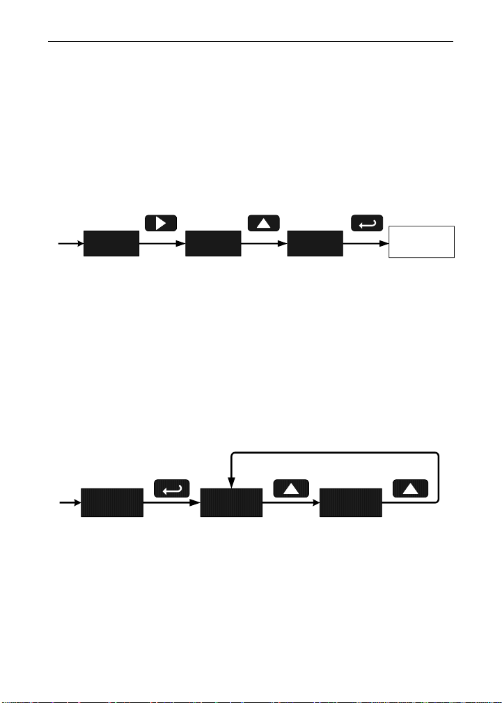
Setting Up the Meter (setu)
The Setup menu is used to select:
1. Input signal the meter will accept
2. Units (F or C) for temperature inputs
Press the Enter/Ack button to access any menu or press Up arrow button to scroll through choices. Press the Menu button to exit at any time.
0012 0022 0032
Increment Digit
Value
Next
Setting
Select Next Digit Accept Setting
setu inpt F C
Page 19
Sabre T Model PD743 Temperature Meter Instruction Manual
19
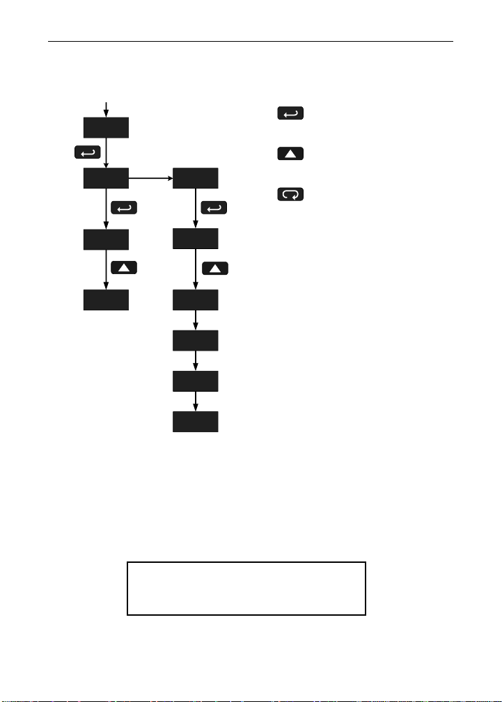
Setting the Input Signal (inpt)
Enter the Input menu to set up the meter to display thermocouple (tC)
or RTD (rtd) inputs.
If RTD is selected, the display shows A385 or A392. Select the coefficient to match the RTD sensor, either 0.00385 (European curve) or
0.00392 (American curve).
If TC is selected, scroll through the thermocouple types and select the
type matching the TC sensor.
The input signal must be connected to the appropriate input terminals
and the RTD/TC selector switch must be set accordingly, see Figure 4
on page 11.
For thermocouple inputs, allow at
least 30 minutes warm-up time for
meter to reach specified accuracy.
rtd tC
a385
a392
0 j
1 k
2 t
3 t.0
4 e
Press Enter/Ack to
Make Selections
Press Up Arrow to
Scroll Through Choices
Press Menu to
Exit at any Time
J
K
T
T.1
E
inpt
Page 20
Sabre T Model PD743 Temperature Meter Instruction Manual
20
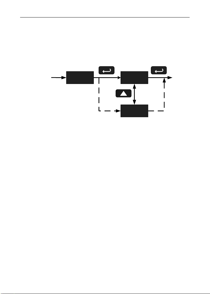
Setting the Temperature Scale (F C)
The meter can be set to display temperature in degrees Fahrenheit or
Celsius.
Press Up arrow to change selection.
Press Enter/Ack to accept.
f C
o
f
Next
Previous
o
C
Page 21
Sabre T Model PD743 Temperature Meter Instruction Manual
21
Programming the Meter (prog)
It is very important to read the following information, before proceeding
to program the meter:
• There is no need to recalibrate the meter when first received from
the factory.
• The meter is factory calibrated prior to shipment, for all input
types, in degrees Fahrenheit. The calibration equipment is certified
to NIST standards.
The Program menu contains the Calibrate menu.
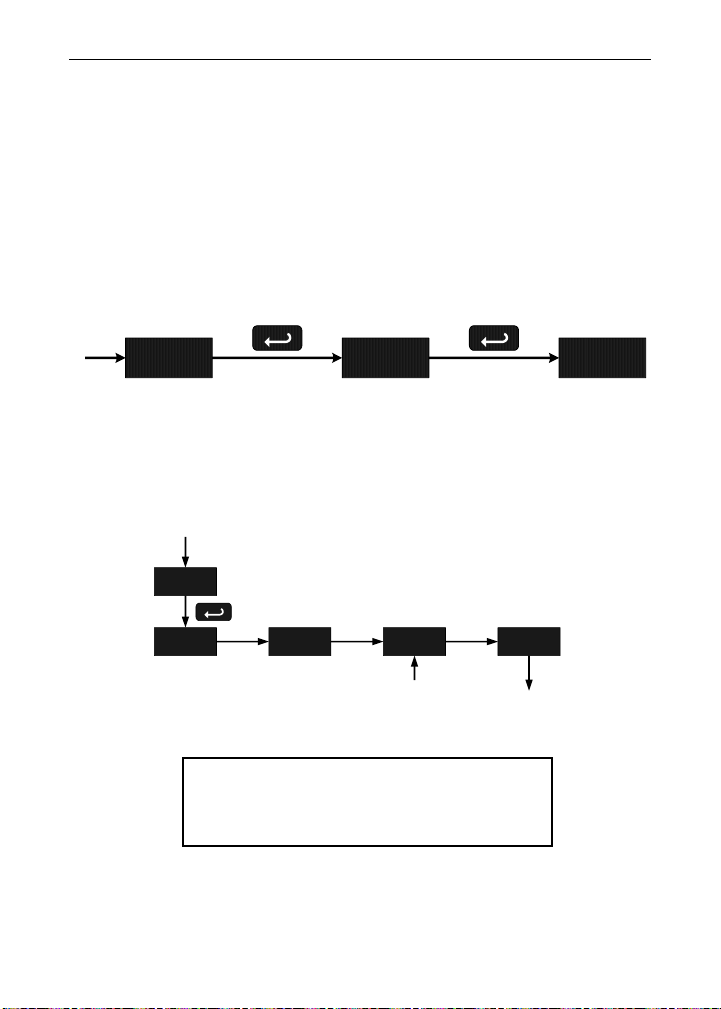
Recalibrating Temperature Inputs (Cal)
Remember, the meter is calibrated at the factory prior to shipment. Recalibration is recommended at least every twelve months.
The Calibration (CAL) menu is used to recalibrate the thermocouple and
RTD inputs.
Allow at least 30 minutes warm-up time be-
fore performing recalibration procedure to
ensure specified accuracy.
prog Cal inp1
inp1 dis1 0032
Set Display 1
Value
inp2
Calibrate
Input 2
Cal
Display
Flashes
Accepting
Input
See Scaling the Meter for Button
Functions Description
Page 22
Sabre T Model PD743 Temperature Meter Instruction Manual
22
Error Message (Err)
An error message indicates that the calibration process was not successful.
After the error message is displayed, the meter reverts to input 1, allowing the appropriate input signals to be applied.
The error message might be caused by any of the following conditions:
1. Input signal is not connected to the proper terminals or it is connected backwards.
2. Wrong signal selection in Setup menu.
3. Minimum input span requirements not maintained.
4. Input 1 signal inadvertently applied to calibrate input 2.
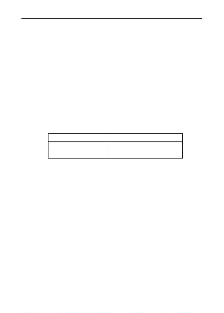
Minimum Input Span
The minimum input span is the minimum difference between input 1 and
input 2 signals required to complete the calibration of the meter.
Input range
Input 1 & input 2 span
TC
100F (56C)
RTD
50F (28C)
Page 23
Sabre T Model PD743 Temperature Meter Instruction Manual
23
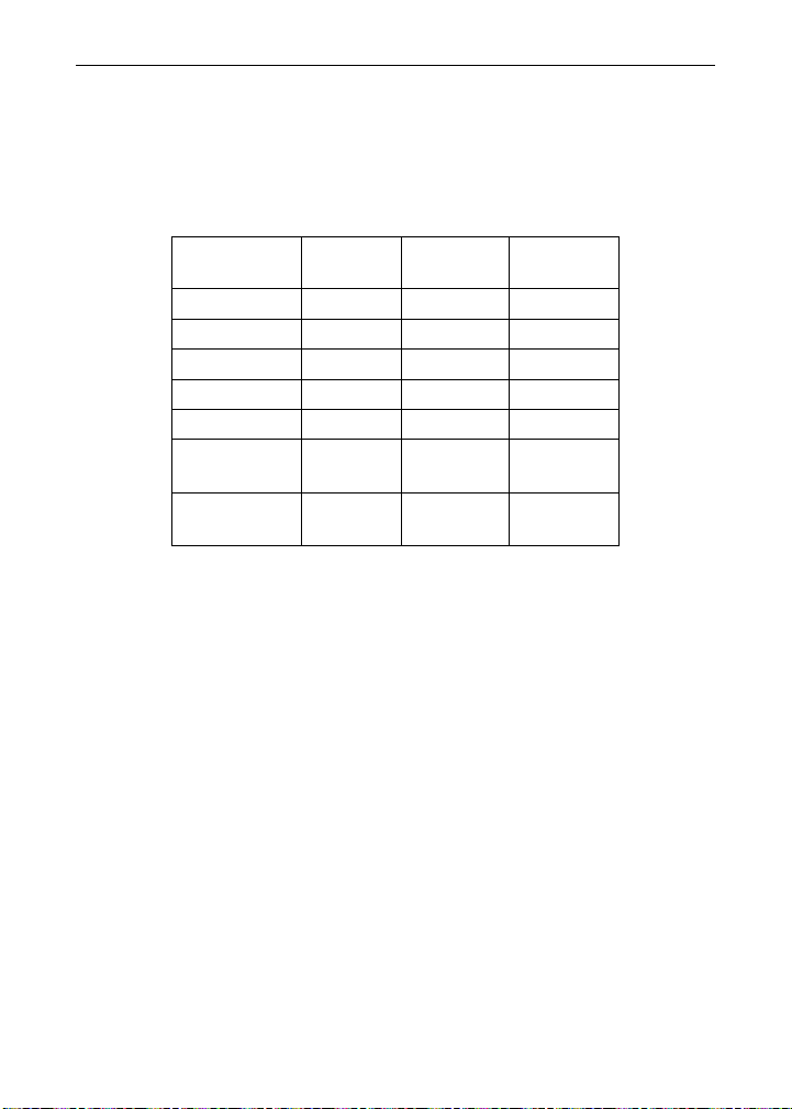
Recommended Calibration Points
To recalibrate the meter, it is recommended to use the Fahrenheit scale;
this will give a greater degree of accuracy to the calibration. The scale
can be changed to the Celsius scale after calibration is completed. The
meter will display temperature accurately in any scale. The following table shows the recommended low and high calibration points for all
types.
Type of input
Input 1
(Low)
Input 2
(High)
Check
(Middle)
Type J T/C
32F
1182F
600F
Type K T/C
32F
1893F
960F
Type T T/C
32F
693F
360F
Type T T/C
32.0F
693.0F
360.0F
Type E T/C
32F
1652F
840F
100 RTD
(0.00385)
32F
100
1148F
320.12
590F
215.61
100 RTD
(0.00392)
32F
100
1127F
320.89
580F
215.87
Recalibration Procedure for Temperature Inputs
1. Connect signal to the meter using the appropriate wire (e.g.
type J thermocouple wire to recalibrate type J input), see page
11.
2. Set up the meter to accept the selected input (e.g. type J T/C),
see page 19.
3. Set up the meter to display temperature in degrees Fahrenheit,
see page 20.
4. Apply signal corresponding to input 1 (e.g. 32°F) and program
display 1 to read 32.
5. Apply signal corresponding to input 2 (e.g. 1182°F for type J)
and program display 2 accordingly.
6. After the meter accepts input 2, the display flashes the mes-
sage CJr, indicating that the meter is sensing the cold junction
reference. This completes the recalibration procedure for the
selected input.
Page 24
Sabre T Model PD743 Temperature Meter Instruction Manual
24
Setting Up the Password (pass)
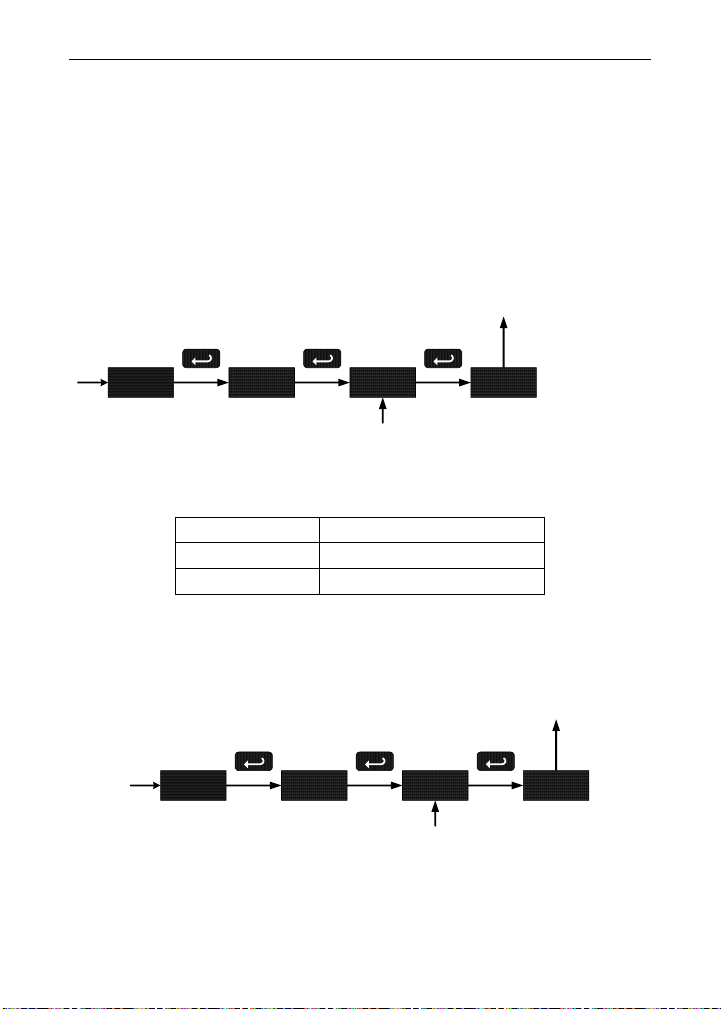
The Password menu is used to program a four-digit password to prevent unauthorized changes to the programmed parameter settings.
Locking the Meter
Enter the Password menu and program a four-digit password.
For instructions on how to program numeric values see Setting Numeric
Values, page 18.
Record the password for future reference. If appropriate, it may be recorded in the space provided.
Model:
Serial Number:
Password:
__ __ __ __
Unlocking the Meter
If the meter is password protected, the correct password must be entered in order to make changes to the parameter settings.
pass unlC 0000
Program
Password
loCd
Run Mode
pass loCd 0000
Enter
Password
unlC
Run Mode
Page 25

Sabre T Model PD743 Temperature Meter Instruction Manual
25
Entering the correct four-digit number sets the password to 0000, disabling the protection.
Changes to the programmed parameter settings are allowed only with
the password set to 0000.
If the password entered is incorrect, the meter displays LoCd (Locked)
for about two seconds, then it returns to Run Mode. To try again, press
Enter/Ack while the Locked message is displayed.
Forgot the Password?
The password may be disabled by the following
procedure:
1. Note display reading prior to pressing the Menu
button. Ignore decimal point and sign.
2. Access the Password menu, add 2 to the noted
reading and enter that number as the password
(e.g. display reading = -1.23, password = 0125).
Page 26
Sabre T Model PD743 Temperature Meter Instruction Manual
26
OPERATION
The temperature inputs are displayed according to the input type and
temperature units (F or C) selected. Type T thermocouples can be displayed with either 1 or 0.1 resolution.
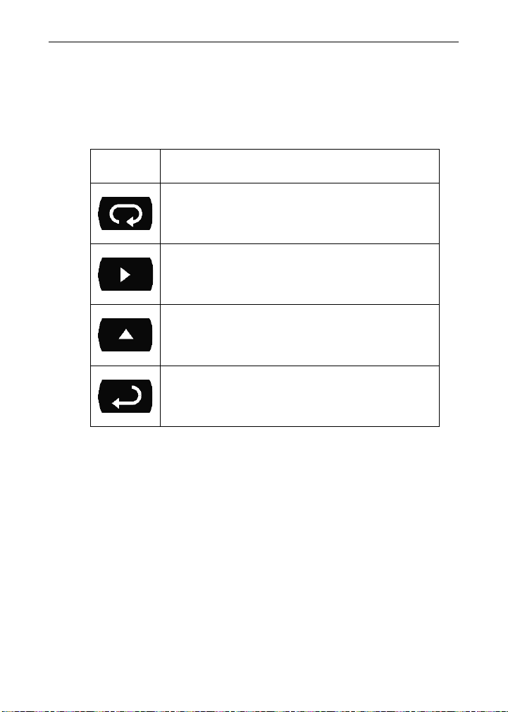
Front Panel Buttons Operation
Button
Symbol
Description
Press to enter or exit Programming Mode,
view settings, or exit Max/Min readings
Press to reset Max/Min readings
Press to display Max/Min readings
alternately
Press to display Max/Min reading
indefinitely while displaying Max/Min
Page 27
Sabre T Model PD743 Temperature Meter Instruction Manual
27
Maximum/Minimum Readings
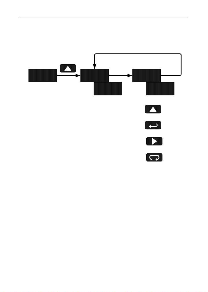
The main function of the front panel buttons during operation is to display the maximum and minimum readings reached by the process.
1. Press Up arrow/Max button to display maximum reading since the
last reset/power-up.
2. Press Up arrow/Max again to display the minimum reading since
the last reset/power-up.
3. Press Enter/Ack to hold Max/Min display reading, the meter will
continue to track new Max/Min readings.
4. If Enter/Ack is not pressed, the Max/Min display reading will time
out after ten seconds and the meter will return to display the actual
reading.
5. Press Right arrow/Reset button to reset Max/Min while reading is
being displayed. Max/Min display readings are reset to actual
reading.
958 Hi lo
Actual
Reading
1743 740
Press Enter to Hold Max/Min
Press Up to Display and
Toggle Max/Min
Press Right to Reset Max/Min
Press Menu to Exit Max/Min
Page 28
Sabre T Model PD743 Temperature Meter Instruction Manual
28
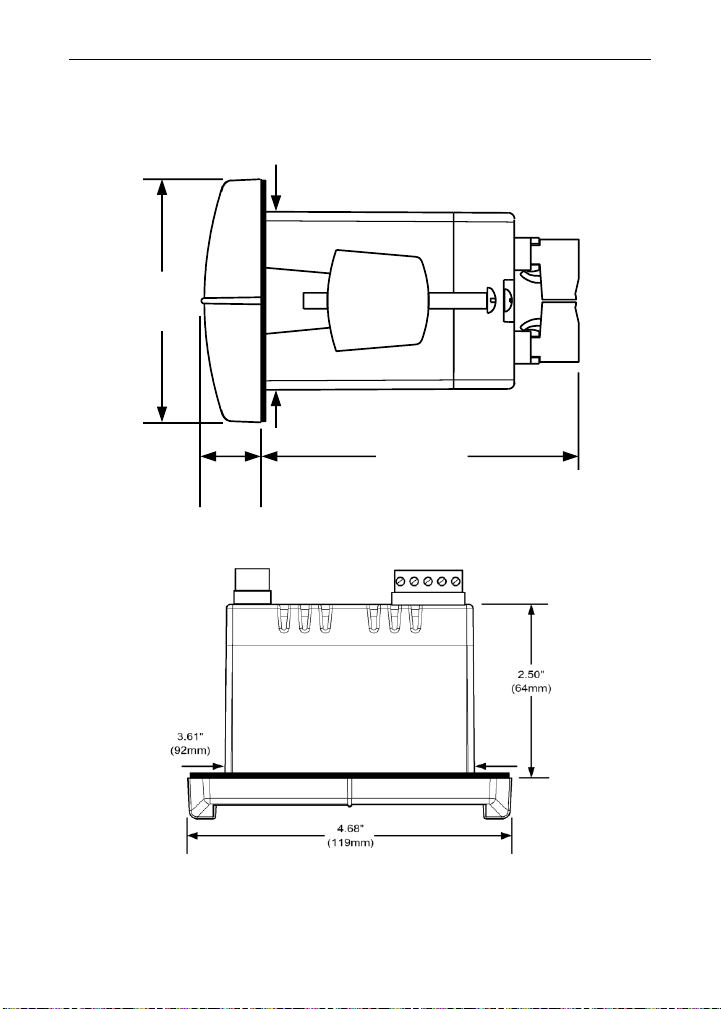
MOUNTING DIMENSIONS
Figure 8. Meter Dimensions - Side View
Figure 9. Case Dimensions - Top View
1.76"
(45mm)
0.59"
(15mm)
3.2"
(81mm)
2.45"
(62mm)
Page 29
Sabre T Model PD743 Temperature Meter Instruction Manual
29
TROUBLESHOOTING
The rugged design and the user-friendly interface of the meter should
make it unusual for the installer or operator to refer to this section of the
manual.
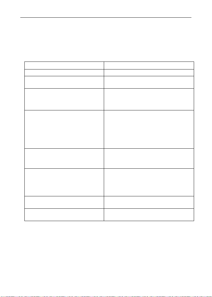
Troubleshooting Tips
Symptom
Check/Action
No display at all
Check power at power connector
Not able to change setup or programming, LoCd is displayed
Meter is locked, enter correct four-digit
password to unlock
Meter displays error message during calibration (err)
Check:
1. Signal connections
2. Input selected in Setup menu
3. Minimum input span requirements
Meter displays
• open
• 9999
• -1999
• Displays negative number,
not responding to RTD.
Check:
1. Input selected in Setup menu
2. TC/RTD Switch position
3. Corresponding signal at Signal
connector
Display alternates between
1. Hi and a number
2. Lo and a number
Press Menu to exit Max/Min
display readings.
Inaccurate temperature reading
Check:
1. Temperature units (F or C)
2. TC type or RTD curve selected
3. Type of TC wire used
4. Calibration
If the display locks up or the meter
does not respond at all
Cycle the power to restart the
microprocessor.
Other symptoms not described
above
Call Technical Support for
assistance.
Page 30
Sabre T Model PD743 Temperature Meter Instruction Manual
30
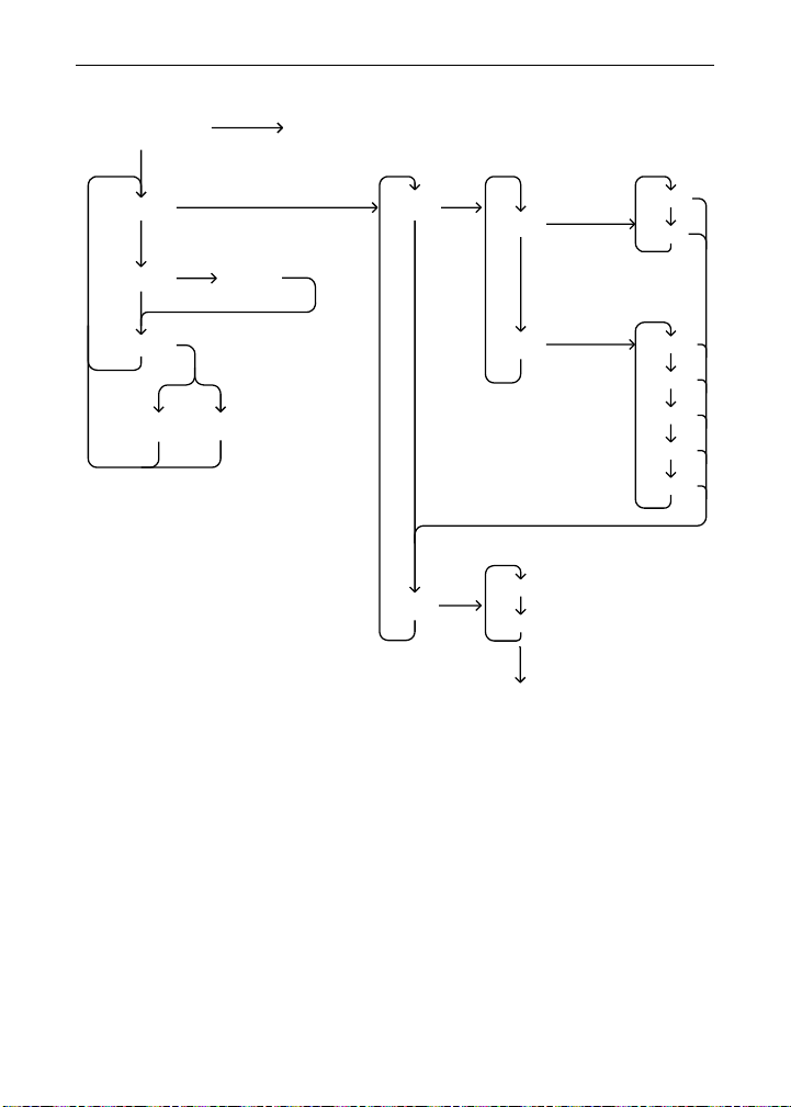
QUICK USER INTERFACE REFERENCE GUIDE
Run Mode
Setup
Program
Password
Display
Max/Min
Input
RTD
TC
A385
A392
Type J
Type K
Type T
Type T.0
Type E
F
C
F or C
To Program
Locked Unlocked
Calibrate
Page 31

Sabre T Model PD743 Temperature Meter Instruction Manual
LIM743_F
SFT031 Ver 3.2 & up
02/22
How to Contact Precision Digital
• For Technical Support please
Call: (800) 610-5239 or (508) 655-7300
Fax: (508) 655-8990
Email: [email protected]
• For Sales Support or to place an order please
Call: (800) 343-1001 or (508) 655-7300
Fax: (508) 655-8990
Email: [email protected]
• For Calibration information visit
www.predig.com
• For the latest version of this manual please visit
www.predig.com
 Loading...