

Page 1
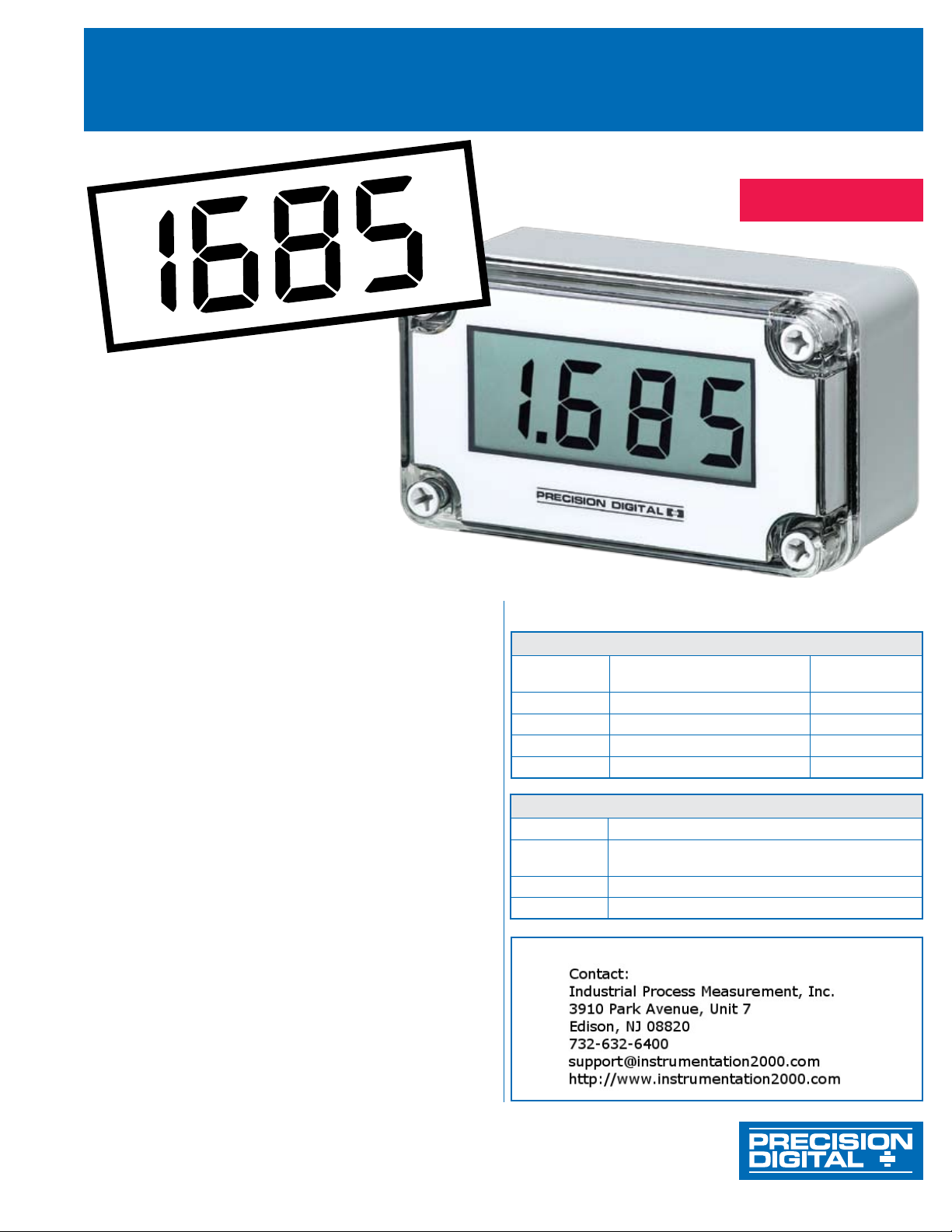
MODEL PD685 3½ DIGIT NEMA 4X
LOOP-POWERED METER
MODEL PD685
Actual Size Digits
1 V Drop•
1" High Display•
Operates From •
-40 to 85°C
SPECIFICATIONS
Except where noted all specifications apply to operation at +25°C.
Input: 4-20 mA @ 30 VDC maximum
Display: 1.0" (25.4 mm) LCD, 3½ digits; 1999
Accuracy: ±0.1% FS ±1 count
Decimal Point: User selectable
Calibration: Two-step; non-interacting zero and span
Calibration Range: 4 mA input: -1000 to +1000
20 mA input: between 20 and 2000 counts > 4 mA display
Display Update Rate: 2.5/second
Maximum Input Current: 30 mA
Maximum Voltage Drop: 1 V @ 20 mA
Operating Temperature: -40 to 85°C
Storage Temperature: -40 to 85°C
Relative Humidity: 0 to 90% non-condensing
Enclosure: Impact-resistant plastic; body: gray ABS; cover: clear
polycarbonate; NEMA 4X, IP66/67
Connections: Removable screw terminals accept 12 to 26 AWG
Conduit Hole: One ½" conduit hole provided; refer to Ordering
Information to specify conduit hole location; request models with
rear conduit hole (-X) for panel mounting applications.
Weight: 12 oz (340 g)
Warranty: 2 years parts & labor
Disclaimer
The infor mation contained in thi s d ocument is sub ject to chang e w ithout notice. Preci sion Digital
Corporation makes no representations or warranties with respect to the contents hereof, and
specically disclaims any implied war ranties of merchant ability or tness for a particular purpose.
©200 9 Precision Digital Cor porati on. All rights res erved.
ORDERING INFORMATION
PD685 NEMA 4X Loop-Powered Meter
Model Description
PD685 3½ Digit Loop-Powered Meter Bottom
PD685-X 3½ Digit Loop-Powered Meter Rear
PD685-Y 3½ Digit Loop-Powered Meter Top
PD685-Z 3½ Digit Loop-Powered Meter None
Accessories
Model Description
PDA6844
PDA6845 2" Pipe Mounting Kit (zinc plated steel)
PDA6845-SS 2" Pipe Mounting Kit (stainless steel)
Panel Mount Kit
(does not provide NEMA 4X seal to panel)
Your Local Distributor is:
½" Conduit
Hole Location
Precision Digital corPoration
www.predig.com
Page 2
MODEL PD685 3½ DIGIT NEMA 4X LOOP-POWERED METER
SIDE VIEW
Mounting
Holes
Located
Beneath
Cover
Screws
E
F
FRONT VIEW
D
A C
B
Figure 4
Dimensions and Mounting Information
LO CALIBRATION CONTROL
HI CALIBRATION CONTROL
BALANCE CONTROL
(factory adjust only)
DISPLAY PCB COMPONENT SIDE
(may be removed for bench calibration)
S-
S-
S+
S-
S+
S+
BLACK
RED
LOOP JUMPER
CALIBRATED
CURRENT SOURCE
INPUT SIGNAL PCB
(mounted to base of enclosure)
+
-
DP1
DP2
DP3
Figure 1
Calibrator Connected to
Input Signal PCB
INPUT SIGNAL PCB
LOOP JUMPER
(remove when Display PCB is connected)
TRANSMITTER
POWER
SUPPLY
+
+
-
-
4-20mA
S+ S+S- S-
Field wiring is
made to the
Input Signal PCB
which is mounted
to the base of
the enclosure.
Figure 2
Control loop Connected
to Input Signal PCB
S+
S-
BLACKRED
DISPLAY PCB
COMPONENT SIDE
CALIBRATED
CURRENT SOURCE
DP1
DP2
DP3
Figure 3
The Display PCB may be removed from the enclosure
for bench calibration. Loop Jumper must be installed
on Input Signal PCB to maintain loop,
refer to procedures below.
Calibrator Connected to Display PCB
Protect enclosure from exposure to chemical solvents and excessive ultraviolet (UV) light (e.g. sunlight).
NOTE: To prevent damage to electronic components caused by electrostatic
discharge, a grounding strap should be worn when
servicing the display.
Conduit Installation Instructions
1. Remove the Display PCB from the enclosure
2. Connect ½” conduit fittings to the hole in the enclosure
3. Connect conduit (with attached hubs*) to the enclosure
* Use only conduit hubs that are designed to maintain NEMA 4X or IP ratings.
Note: Please read PD686 Intrinsic Safety Barrier Connections for more information
pertaining to conduit holes.
Mounting Instructions
1. Remove the enclosure cover from the base.
2. Insert mounting hardware into mounting holes in enclosure base (see Figure 4).
3. Secure the enclosure base to the mounting surface using the inserted hardware.
4. Re-attach the enclosure cover to the base.
SETUP
Only a calibrated current source and a screwdriver are needed for calibration.
Calibration Connections
To access the input terminals it is necessary to remove the enclosure cover and the
Display PCB. This is done by loosening the four screws on the enclosure cover and
removing the cover. Completely loosen the left screw that holds the Display PCB
to the enclosure and loosen the right screw about four turns so the Display PCB
remains attached to the enclosure. Rotate the Display PCB 90° to gain access to the
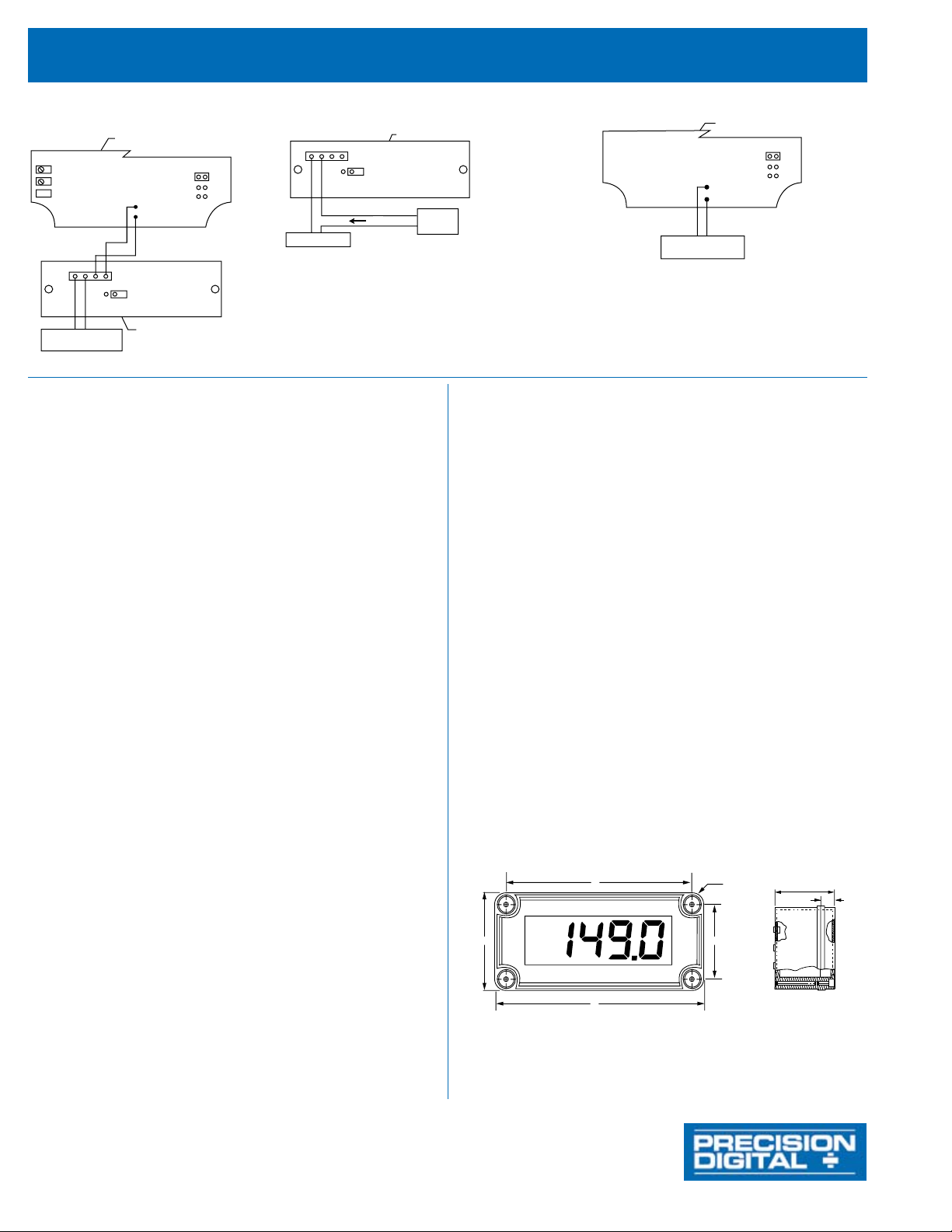
Input Signal PCB. Next, connect a calibrated current source as illustrated in Figure 1.
Decimal Point Selection
The decimal point jumper array is located in the lower right corner of the Display PCB
next to the display. It is labeled DP1, DP2, DP3. Place a jumper over both pins of DP1
for a display of 199.9, DP2 for 19.99, or DP3 for 1.999.
Calibration
LO and HI calibration controls are located to the left of the display
(see Figure 1). Apply a signal equal to 4 mA and adjust the LO control to display the
desired reading. Apply a signal between 16 and 20 mA and adjust the HI control to
display the desired reading. Complete the calibration procedure by making any minor
adjustments to the LO and HI controls.
Installation
Installation of the meter involves removing the Display PCB from its enclosure and
connecting a conduit fitting. Use conduit and fittings (not included) suitable for the
degree of ingress protection required.
Mounting holes are located at each corner of the enclosure. Refer to Figure 4.
Loop Connections
Disconnect power to the loop and install the meter as illustrated in Figure 2. Replace
the enclosure cover.
Precision Digital corPoration
89 October Hill Rd • Holliston MA 01746 USA • Tel (800) 343-1001 • Fax (508) 655-8990
Removing Display PCB From the Loop
The Display PCB and Input Signal PCB are connected together with one black and
one red wire. The wires are soldered to the Display PCB and connected to a screw
terminal connector on the Input Signal PCB.
To remove Display PCB:
1. Loosen the four screws on the enclosure cover and remove the cover from the
enclosure base.
2. Completely loosen the left-side screw holding the Display PCB to the enclosure.
Loosen the right-side screw four turns so the Display PCB remains secure to the
enclosure.
3. Rotate the Display PCB 90° to gain access to the Input Signal PCB.
4. Install Loop Jumper over both pins to bypass Display PCB and allow the signal to
flow through the Loop Jumper. The display will go off when the jumper is installed.
Disconnect the black and red signal wires from the screw terminal connector.
5.
6. Loosen completely the right-side screw and lift Display PCB from the enclosure.
Care should be taken to prevent static electricity from damaging the electronic
circuitry.
7. Restore enclosure cover to the base to prevent contamination of components.
Restoring Display PCB to the Loop
1. Remove enclosure cover as described in step 1 in the preceding section.
2. Secure Display PCB to enclosure using right-side screw; do not tighten screw to
allow rotation of Display PCB while accessing Input Signal PCB.
3. Connect red wire to S+ terminal and black wire to S- terminal, as shown in Figure 1.
4. Remove Loop Jumper to allow the signal to flow through Display PCB (save pushon jumper by placing over one pin only).
5. Tighten screws holding Display PCB and install enclosure cover.
Servicing Display PCB Outside the Loop
Two modes of input signal allow the user to remove the Display PCB for service
without interrupting the loop as indicated above and operate the Display PCB at
another location. The loop remains connected to the Input Signal PCB while the
Display PCB is absent for service. The user may operate the Display PCB at another
location by connecting a signal to the S+ and S- wires on the Display PCB as
illustrated in Figure 3.
A: 3.15" (80 mm) C: 2.36" (60 mm) E: 2.56" (65 mm)
B: 5.51" (140 mm) D: 4.72" (120 mm) F: 0.79" (20 mm)
LDS685_C 06/09
www.predig.com
 Loading...