

Page 1
PRECISION DIGITAL CORPORATION
233 South Street • Hopkinton MA 01748 USA
Tel (800) 343-1001 • Fax (508) 655-8990
www.predig.com
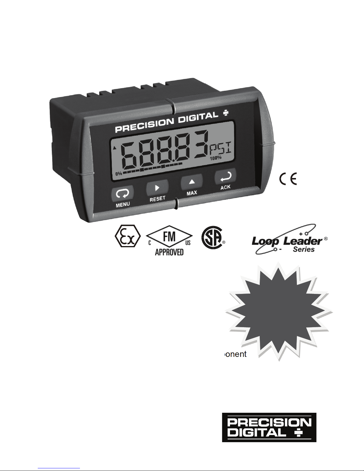
PD683 & PD688
LOOP-POWERED METERS
Instruction Manual
• 2 V drop (5.7 V with backlight)
• 5-Digit LCD, 0.6" (15.2 mm) High
• Custom Engineering Units
• 20-Segment Bargraph Display
• Type 4X, NEMA 4X, IP65 Front
• Maximum & Minimum Display
• Linear, Square Root, or Programmable Exponent
• Non-Volatile Memory – No Battery Needed
Loop-
Powered
Backlight
Standard!
PD688 only
Page 2

PD683 & PD688 Loop-Powered Meters Instruction Manual
2
Disclaimer
The information contained in this document is subject to change
without notice. Precision Digital makes no representations or warranties with respect to the contents hereof, and specifically disclaims
any implied warranties of merchantability or fitness for a particular
purpose.
Registered Trademarks
NORYL® and LEXAN® are registered trademarks of SABIC Innovative Plastics. All other trademarks mentioned in this document are
the property of their respective owners.
© 2016 Precision Digital Corporation. All rights reserved.
Page 3
PD683 & PD688 Loop-Powered Meters Instruction Manual
3
INTRODUCTION
The PD688 is an intrinsically safe and non-incendive loop-powered meter
approved for hazardous area locations. The PD683 is a general-purpose
loop-powered meter for safe area applications. The four front panel buttons make the setup and programming an easy task. Five digits, bargraph, engineering units, and trend arrows provide a clear and attractive
presentation of the process.
The square root and programmable exponent functions allow for conditioning of signals from non-linear transmitters without adding external
components to the system and the convenience of scaling without a calibrated signal source make the PD683 & PD688 the ideal choice for process display applications.
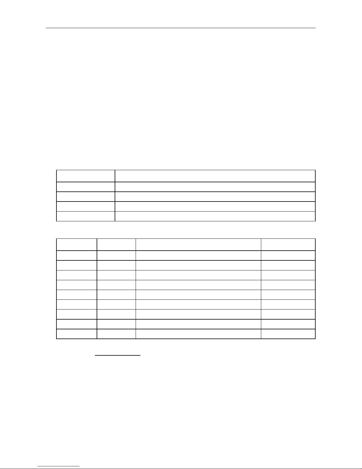
ORDERING INFORMATION
Model Description
PD683-0K0* Loop-Powered Panel Meter for Safe Area
PD684-0K1 Loop-Powered Rate/Totalizer for Safe Area
PD688-0K0* ATEX/FM/CSA Approved Loop-Powered Panel Meter
PD689-0K1 ATEX/FM/CSA Approved Loop-Powered Rate/Totalizer
Enclosures and Accessories
Model Meters Description Mounting
PDA2407 1 Plastic NEMA 4X Enclosure
Inside Cover
PDA2410 3 Plastic NEMA 4X Enclosure
Inside Cover
PDA2411 2 Plastic NEMA 4X Enclosure
Inside Cover
PDA23XX 1-10 Economical Plastic NEMA 4X Enclosure Through Door
PDA25XX 1-10 Plastic NEMA 4X Enclosure
Through Door
PDA26XX 1-6 Stainless Steel NEMA 4X Enclosure
Through Door
PDA27XX 1-6 Steel NEMA 4 Enclosure
Through Door
PDA2801* 1 Low-Cost Plastic NEMA 4X Enclosure
Through Cover
PDA2812 2 Low-Cost Plastic NEMA 4X Enclosure
Through Cover
Note: XX = the last two digits of the model number.
Go to www.predig.com to find individual part numbers.
* Quick Shipment Program product, typically shipped within 2 working days
Page 4

PD683 & PD688 Loop-Powered Meters Instruction Manual
4
Table of Contents
INTRODUCTION ------------------------------------------------------------ 3
ORDERING INFORMATION --------------------------------------------- 3
SPECIFICATIONS ---------------------------------------------------------- 6
General ------------------------------------------------------------------------------- 6
Input ----------------------------------------------------------------------------------- 7
PD688 COMPLIANCE INFORMATION ------------------------------- 8
Ratings and Approvals --------------------------------------------------------- 8
SAFETY INFORMATION ------------------------------------------------- 8
INSTALLATION ------------------------------------------------------------- 9
Unpacking --------------------------------------------------------------------------- 9
Panel Mounting -------------------------------------------------------------------- 9
Wiring Connections ------------------------------------------------------------ 10
4-20 mA Input Connections ------------------------------------------------ 11
SETUP AND PROGRAMMING ---------------------------------------- 12
Front Panel Buttons & Status Indicators ------------------------------- 13
Main Menu Display Functions & Messages ---------------------------- 14
Main Menu ------------------------------------------------------------------------ 15
Setting Numeric Values ------------------------------------------------------ 15
Setting Up the Meter (setup) ------------------------------------------------ 16
Setting the Decimal Point (deC.pt) --------------------------------------- 16
Setting the Units Display (units) ----------------------------------------- 17
Programming the Meter (prog) --------------------------------------------- 18
Scaling the Meter (sCalE) -------------------------------------------------- 19
Calibrating the Meter (Cal) ------------------------------------------------- 20
Recalibrating the Internal Calibration Reference (ICal) ------------ 20
Setting Up the Bargraph (GrapH) ----------------------------------------- 21
Setting Up the Password (pass) ------------------------------------------- 22
Locking the Meter ------------------------------------------------------------ 22
Unlocking the Meter ---------------------------------------------------------- 23
Advanced Features Menu ---------------------------------------------------- 24
Advanced Features Menu & Display Messages ---------------------- 25
Math Functions (lnear, Squar, Prog.E, Cutof) ----------------------- 26
Contrast (contr) -------------------------------------------------------------- 27
Noise Filter (fltEr) ---------------------------------------------------------- 27
Noise Filter Bypass (bypAs) ----------------------------------------------- 27
Internal Calibration (ICal) -------------------------------------------------- 28
Information Menu (info) ---------------------------------------------------- 29
Page 5

PD683 & PD688 Loop-Powered Meters Instruction Manual
5
OPERATION ---------------------------------------------------------------- 30
Front Panel Buttons Operation -------------------------------------------- 30
Maximum & Minimum Readings (Max& MiN) --------------------------- 31
MOUNTING DIMENSIONS ---------------------------------------------- 32
Reset Meter to Factory Defaults ------------------------------------------- 33
Factory Defaults & User Settings ----------------------------------------- 34
TROUBLESHOOTING ---------------------------------------------------- 35
Troubleshooting Tips --------------------------------------------------------- 35
QUICK USER INTERFACE REFERENCE GUIDE ---------------- 36
EU DECLARATION OF CONFORMITY FOR PD688 ------------ 38
EU DECLARATION OF CONFORMITY FOR PD683 ------------ 39
Table of Figures
Figure 1. Panel Cutout and Mounting ................................................. 9
Figure 2. PD683 & PD688 Rear View ................................................. 10
Figure 3. PD683 Input Connections with Backlight ......................... 11
Figure 4. PD683 Input Connections without Backlight ................... 11
Figure 5. Meter Dimensions – Side View .......................................... 32
Figure 6. Case Dimensions – Top View ............................................ 32
Page 6

PD683 & PD688 Loop-Powered Meters Instruction Manual
6
SPECIFICATIONS
Except where noted all specifications apply to operation at +25°C.
General
DISPLAY Five digits
(-99999 to 99999)
0.60" (15.2 mm) high, 7-segment, automatic lead zero blanking.
Four characters
(Engineering Units)
0.25" (6.4 mm) high, 14 segment.
Bargraph 20-segment, 0% to 100% indication.
Trend arrows Up and down trend indication.
Backlight Orange (intensity varies with signal)
DISPLAY
UPDATE RATE
1 update/second
OVERRANGE
Display flashes
99999
UNDERRANGE
Display flashes
-99999
PROGRAMMING
METHOD
Four front panel buttons
NOISE FILTER Programmable from 1 to 199
RECALIBRATION Recalibration is recommended at least every 12 months.
MAX/MIN
DISPLAY
Max/min readings reached by the process are stored until
reset by the user or until power to the meter is turned off.
PASSWORD Programmable password restricts modification of
programmed settings.
NON-VOLATILE
MEMORY
All programmed settings are stored in non-volatile memory
for a minimum of ten years if power is lost.
NORMAL MODE
REJECTION
64 dB at 50/60 Hz
ENVIRONMENTAL Operating temperature range: -30 to 65°C (-40°C allowed)*
Storage temperature range: -40 to 65°C
Relative humidity: 0 to 90% non-condensing
*Below -30°C, the LCD becomes less readable.
CONNECTIONS Removable screw terminals accept 12 to 22 AWG wire
ENCLOSURE &
MATERIALS
1/8 DIN, high impact plastic, UL 94V-0, color: gray
NORYL® Polyphenylene Ether & Polystyrene blend (PPE
PS) Resin
LEXAN® Polycarbonate (PC) Film
Page 7

PD683 & PD688 Loop-Powered Meters Instruction Manual
7
MOUNTING 1/8 DIN panel cutout required. Two panel mounting
bracket assemblies provided
TIGHTENING
TORQUE
Screw terminal connectors: 4.5 lb-in (0.5 Nm)
Mounting screws: 8.0 lb-in max. (0.9 Nm)
OVERALL
DIMENSIONS
4.68" x 2.45" x 3.79" (119 mm x 62 mm x 96 mm)
(W x H x D)
WEIGHT 5.7 oz (162 g)
WARRANTY 3 years parts and labor
EXTENDED
WARRANTY
1 or 2 years, refer to Price List for details
Input
ACCURACY
±0.03% of span ±1 count,
square root and programmable exponent: 10-100% FS
FUNCTION
Linear, square root, or programmable exponent
LOW-FLOW
CUTOFF
-99999 to 99999 (-99999 disables cutoff function)
TEMPERATURE
DRIFT
50 PPM/°C from -40 to 65°C ambient
DECIMAL POINT
Up to four decimal places:
d.dddd, dd.ddd, ddd.dd, dddd.d,or ddddd
CALIBRATION
RANGE
An Error message will appear if input 1 and input 2 signals
are too close together.
Input
Range
Minimum Span
Input 1 & Input 2
4-20 mA 0.40 mA
VOLTAGE DROP Without Backlight With Backlight
2.0 V maximum 5.7 V maximum
EQUIVALENT RESISTANCE
100 Ω @ 20 mA 285 Ω @ 20 mA
INPUT
OVERLOAD
Over current protection to 2 A max.
Page 8
PD683 & PD688 Loop-Powered Meters Instruction Manual
8
PD688 COMPLIANCE INFORMATION
Ratings and Approvals
FM & CSA Certified as intrinsically safe with entity for use in:
Class I, Div 1, 2, Groups ABCD
Class II, Div 1, Groups EFG
Class II, Div 2, Groups FG
Class III, Div 1, 2
Class 1, Zone 0, Group IIC
Non-incendive: Suitable for use in Class I, Div 2, Groups ABCD;
Class II, Div 2, Groups FG; Class III, Div 2.
Entity Parameters: Ui: 30 V; Ii: 175 mA; Ci: 0; Li: 0; Pi: 1.0 W
ATEX
II 1G
Ex ia IIC T4
IP65
Ta = -40°C to 65°C
CE EMC Emissions and Immunity:
EN 61326:2013 EMC requirements for Electrical equipment for
measurement and laboratory use – Industrial
IEC 61010-1:2010 & EN 61010-1:2010, including Group and
National Differences as they apply for AU, CA, US and KR
Special Conditions for Safe Use:
The permitted ambient temperature range for the PD688 is -40°C to 65°C.
Year of Construction
This information is contained within the serial number with the first four
digits representing the year and month in the YYMM format.
For FM/CSA applications: The PD688 installation must be performed
in accordance with Control Drawing LIM688-2
For European Community: The PD688 must be installed in accordance with the ATEX directive 94/9/EC, the product certificate
FM08ATEX0058X, and LIM688-2
SAFETY INFORMATION
Installation and service should be performed only by trained
service personnel. Service requiring
replacement of internal components
must be performed at the factory.
CAUTION: Read complete
instructions prior to installation
and operation of the meter.
!
Page 9
PD683 & PD688 Loop-Powered Meters Instruction Manual
9
INSTALLATION
There is no need to remove the meter from its case to complete the installation, wiring, and setup of the meter.
Unpacking
Remove the meter from box. Inspect the packaging and contents for damage. Report damages, if any, to the carrier.
If any part is missing or the meter malfunctions, please contact
your supplier or the factory for assistance.
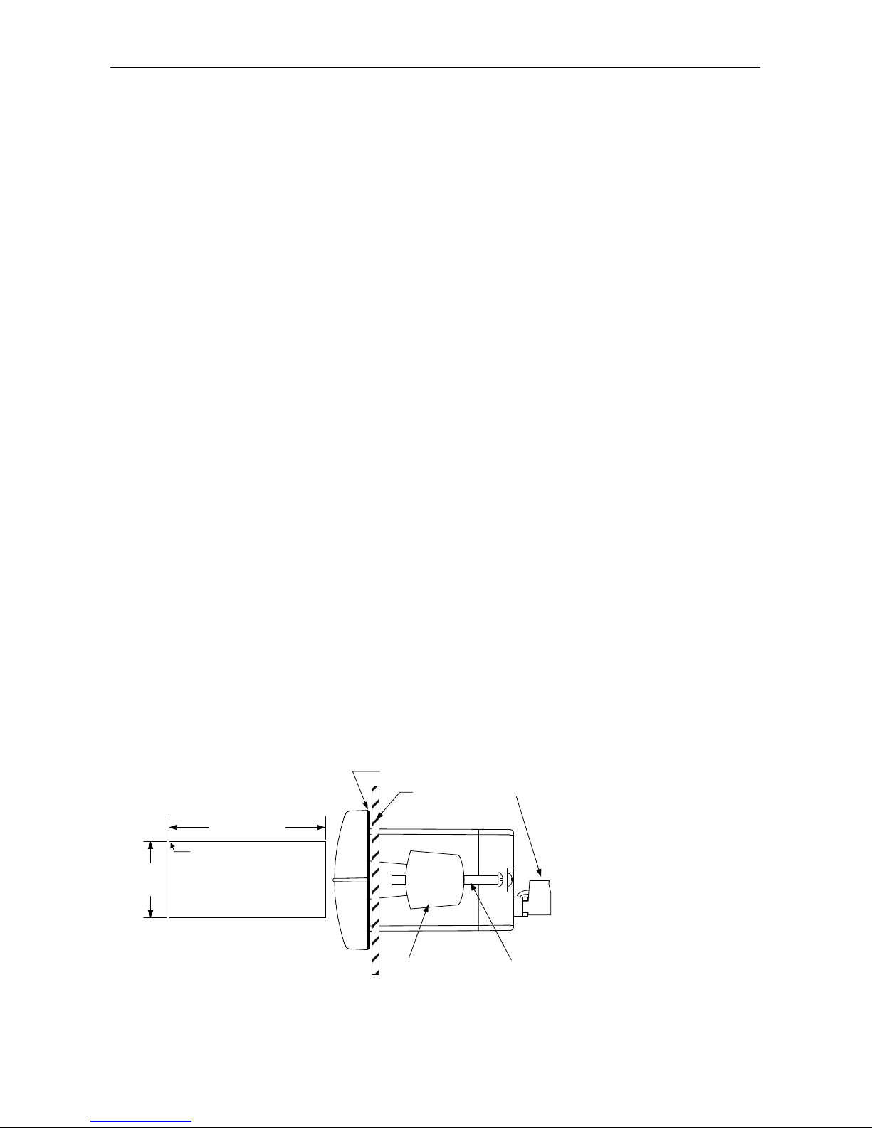
Panel Mounting
• Prepare a standard 1/8 DIN panel cutout – 3.622" x 1.772" (92 mm
x 45 mm). Refer to Mounting Dimensions, page 32 for more details.
• Clearance: allow at least 4" (102 mm) behind the panel for wiring.
• Panel thickness: 0.04" - 0.25" (1.0 mm - 6.4 mm).
Minimum steel/stainless steel panel thickness to maintain watertight
rating: 0.06" (1.5 mm).
Note: A steel or stainless steel panel rather than plastic is
recommended in cases where a watertight or dust-tight seal is
required between the meter and the panel.
• Remove the two mounting brackets provided with the meter (back-off
the two screws so that there is ¼" (6.4 mm) or less through the
bracket. Slide the bracket toward the front of the case and remove).
• Insert meter into the panel cutout.
• Install mounting brackets and tighten the screws against the panel.
To achieve a proper seal, tighten the mounting bracket screws
evenly until meter is snug to the panel along its short side. DO NOT
OVER TIGHTEN, as the rear of the panel may be damaged.
Figure 1. Panel Cutout and Mounting
Panel
Gasket
Mounting
Bracket
Mounting
Screw
Removable
Connector
3.622" (92mm)
1.772"
(45mm)
Panel Cutout
to DIN 43700
Square Corners to 0.060"
(1.5mm) Max Radius
A
B
Tolerances:
A: +0.032 (+0.8mm)
-0.000 (-0.0mm)
B: +0.024 (+0.6mm)
-0.000 (-0.0mm)
See page 32 for Mounting Dimensions
Page 10
PD683 & PD688 Loop-Powered Meters Instruction Manual
10
Wiring Connections
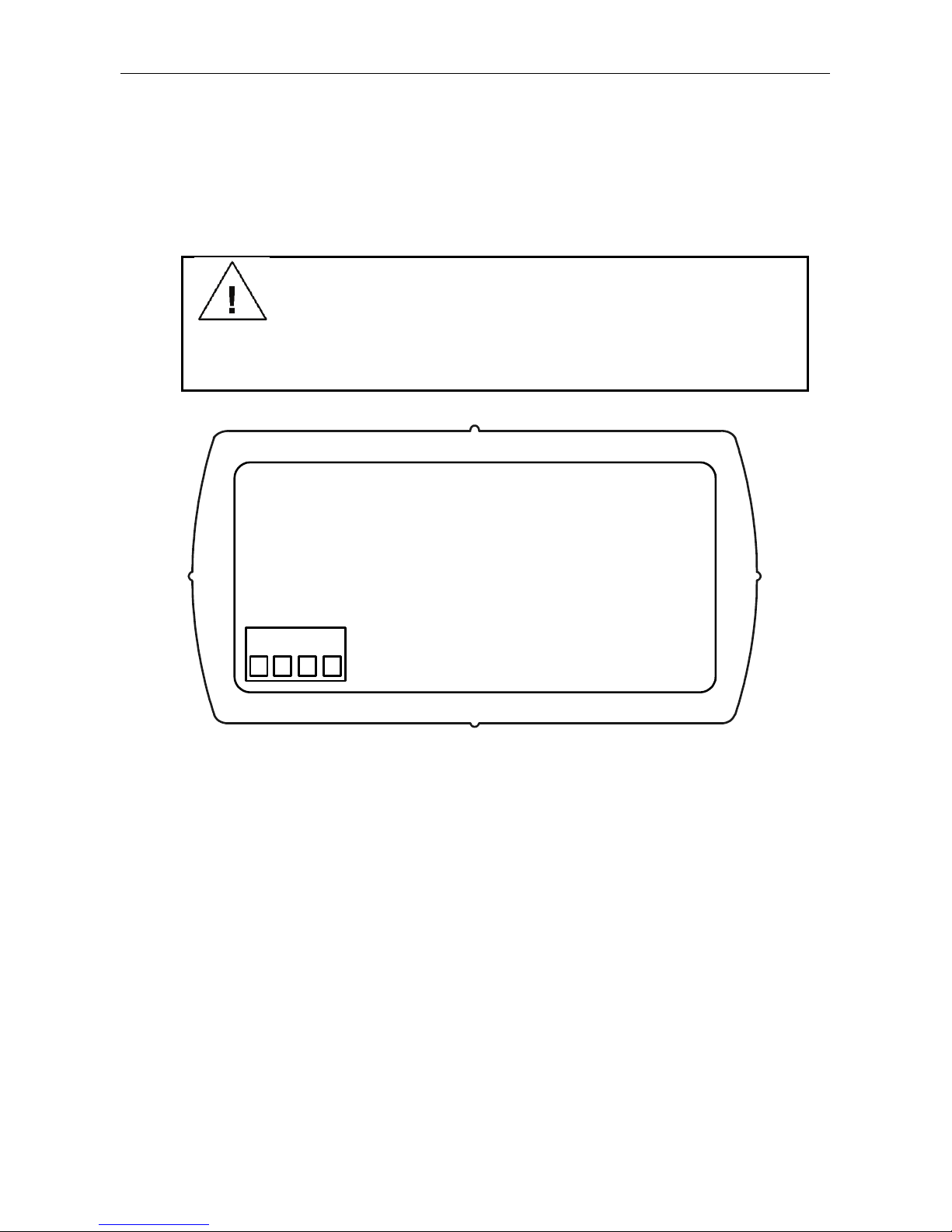
Signal connections are made to a four-terminal removable connector. This
section is only intended for the PD683.
PD688 installation must be performed in accordance with Control
Drawing LIM688-2 in order to meet agency approval ratings.
Observe all safety regulations. Electrical wiring
should be performed in accordance with all agency
requirements and applicable national, state, and local codes to prevent damage to the meter and ensure personnel safety.
Figure 2. PD683 & PD688 Rear View
S+ S- B+ B-
Page 11
PD683 & PD688 Loop-Powered Meters Instruction Manual
11
4-20 mA Input Connections
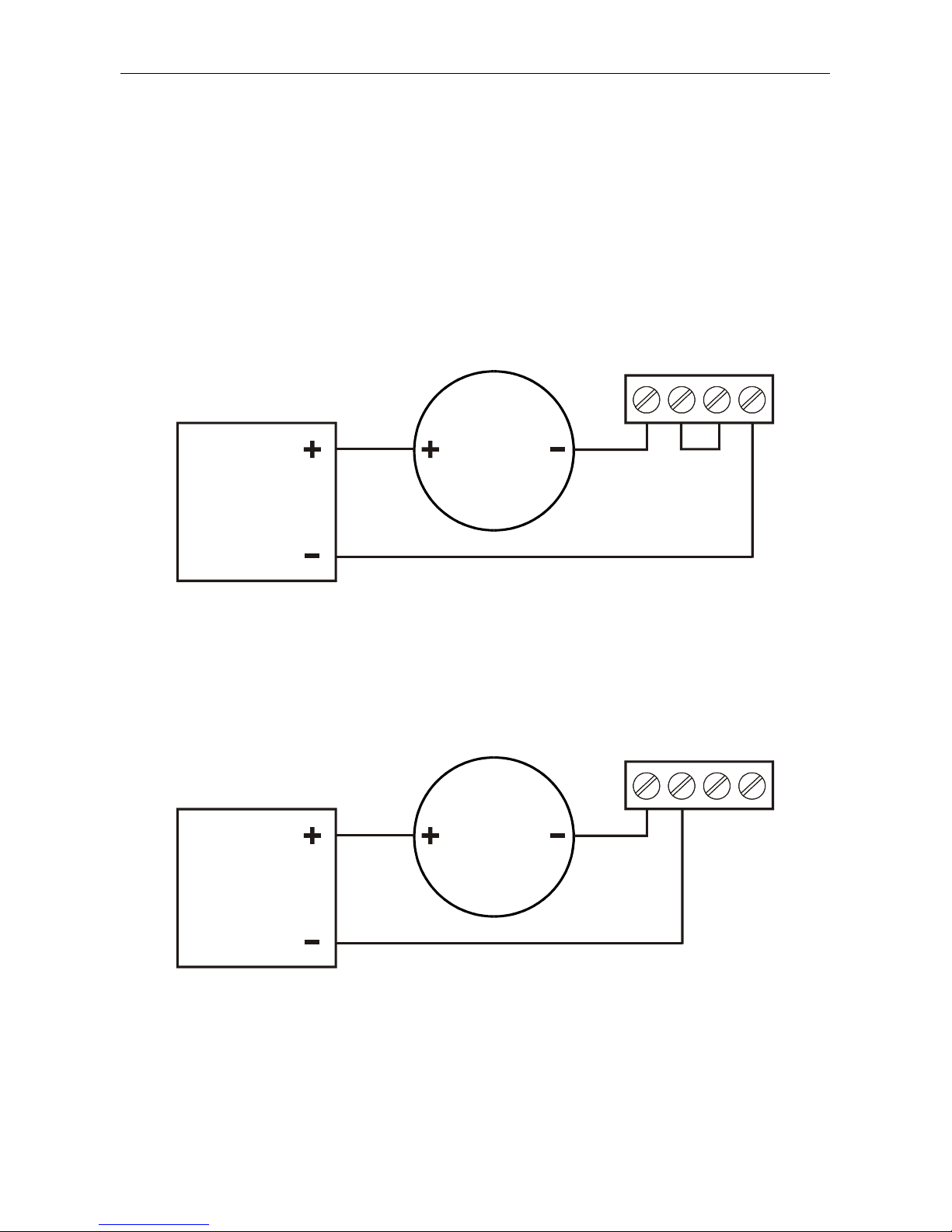
Input connections are made to a four-terminal connector labeled
S+|S-|B+|B-. The loop-powered backlight is an optional configuration and
requires a total maximum voltage drop of 5.7 V. The backlight is recommended for dim lighting conditions and is enabled when wired as shown
in Figure 3. It may be bypassed if installed in bright lighting conditions to
reduce the maximum voltage drop to 2.0 V as shown in Figure 4.
Figure 3. PD683 Input Connections with Backlight
Figure 4. PD683 Input Connections without Backlight
S+ S
- B+ B-
4-20 mA
Transmitter
Power
Supply
S+ S
- B+ B-
4-20 mA
Transmitter
Power
Supply
Page 12
PD683 & PD688 Loop-Powered Meters Instruction Manual
12
SETUP AND PROGRAMMING
• There is no need to recalibrate the meter for
milliamps when first received from the factory.
• The meter is factory calibrated for milliamps
prior to shipment. The calibration equipment
is certified to NIST standards.
Overview
There are no jumpers involved in the setup process of the meter.
Setup and programming is done through the front panel buttons.
After all connections have been completed and verified, apply power to
the loop.
For
Quick User Interface Reference Guide
go to page 36
Page 13
PD683 & PD688 Loop-Powered Meters Instruction Manual
13
Front Panel Buttons & Status Indicators
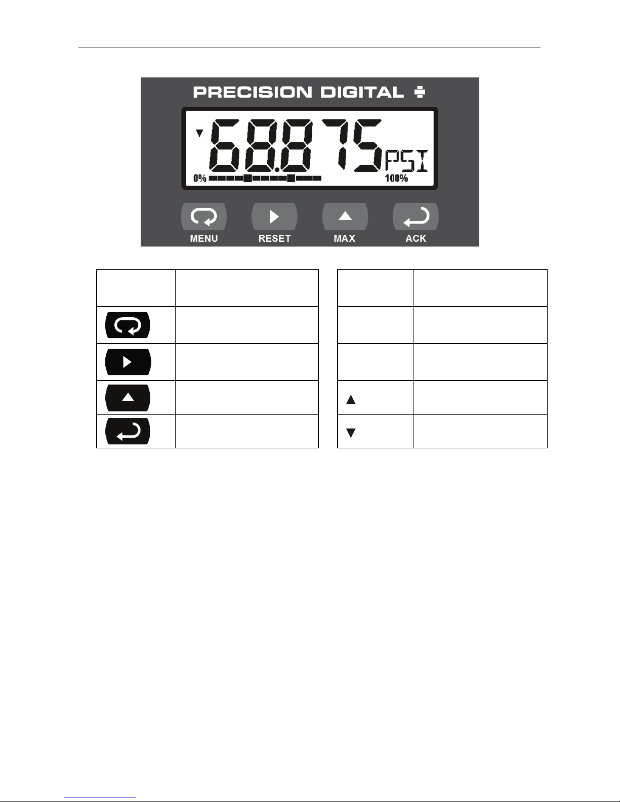
Button
Symbol
Description Symbol Status
Menu
0%
Bargraph
minimum
Right arrow/Reset
100%
Bargraph
maximum
Up arrow/Max
Increasing trend
Enter/Ack
Decreasing trend
•
Press the
Menu
button to enter or exit the Programming Mode at
any time.
•
Press the
Right
arrow button to move to the next digit or decimal
position during programming.
•
Press the Up arrow button to scroll through the menus, decimal
point, or to increment the value of a digit.
•
Press the
Enter/Ack
button to access a menu or to accept a setting.
•
Press and hold the
Menu
button for five seconds to access the
Ad-
vanced Features
of the meter.
Page 14

PD683 & PD688 Loop-Powered Meters Instruction Manual
14
Main Menu Display Functions & Messages
The meter displays various functions and messages during setup, programming, and operation. The following table shows the main menu
functions and messages in the order they appear in the menu.
Display Parameter Action/Setting
setuP
Setup
Enter Setup menu
DeC..pt
Decimal point
Set decimal point
units
Units
Enter the Units menu
prog
Program
Enter the Program menu
sCalE
Scale
Enter the Scale menu
Cal
Calibrate
Enter the Calibrate menu
inpt1
Input 1
Calibrate input 1 signal or program input 1
value
DspL1
Display 1
Program display 1 value
inpt2
Input 2
Calibrate input 2 signal or program input 2
value
DsPl2
Display 2
Program display 2 value
Error
Error
Error, calibration not successful, check signal
graph
Graph
Enter the Graph menu
Pass
Password
Enter the Password menu
unloc
Unlocked
Program password to lock meter
Locd
Locked
Enter password to unlock meter
99999
-99999
Flashing display
Overrange condition
Underrange condition
Page 15
PD683 & PD688 Loop-Powered Meters Instruction Manual
15
Main Menu
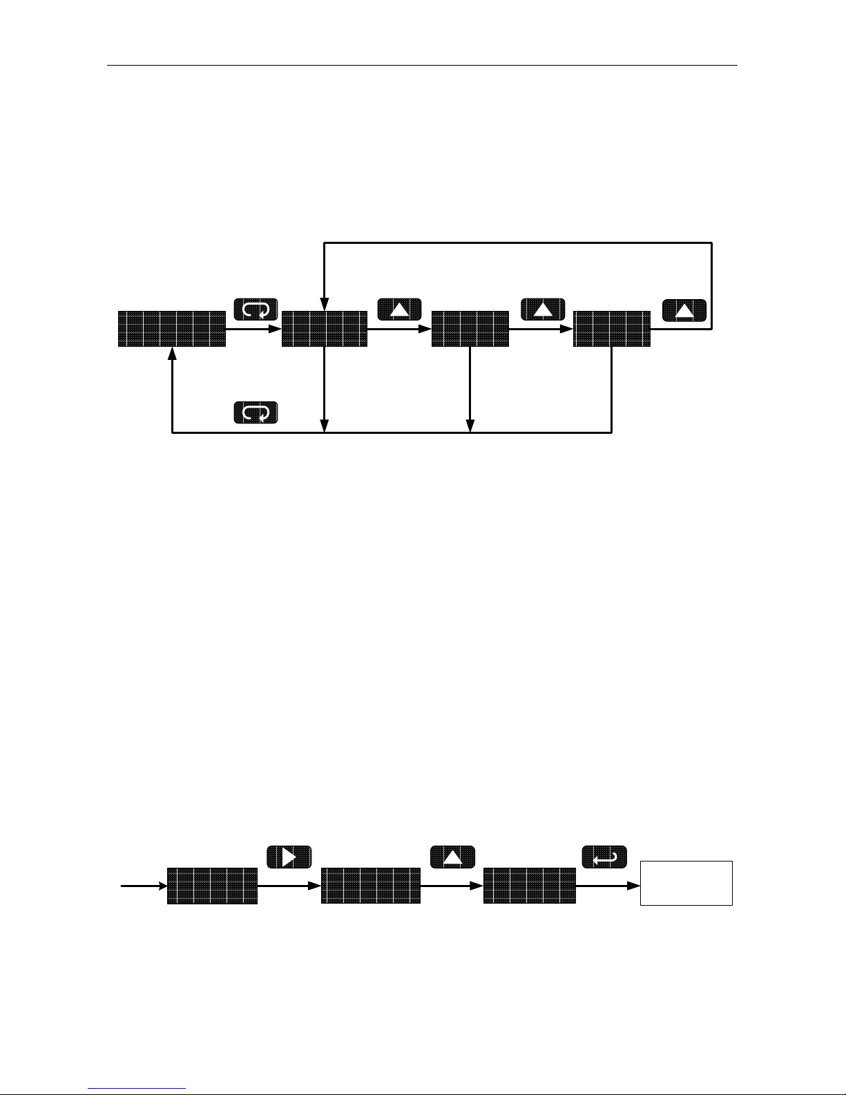
The main menu consists of the most commonly used functions: Setup,
Program, and Password.
• Press Menu button to enter Programming Mode then press Up ar-
row button to scroll main menu.
• Press Menu, at any time, to exit and return to Run Mode. Changes
made to settings prior to pressing Enter/Ack are not saved.
• Changes to the settings are saved to memory only after pressing
Enter/Ack.
• The display moves to the next menu every time a setting is
accepted by pressing Enter/Ack.
Setting Numeric Values
The numeric values are set using the Right and Up arrow buttons.
Press Right arrow to select next digit and Up arrow to increment digit.
The digit being changed blinks.
Press the Enter/Ack button, at any time, to accept a setting or Menu
button to exit without saving changes.
The decimal point is set using the Right or Up arrow button in the
Setup-decimal point menu.
9.2846GPS setup prog pass
Run
Mode
04.000
04.000 05.000
Increment Digit
Value
Next
Setting
Select Next Digit Accept Setting
Page 16
PD683 & PD688 Loop-Powered Meters Instruction Manual
16
Setting Up the Meter (setup)
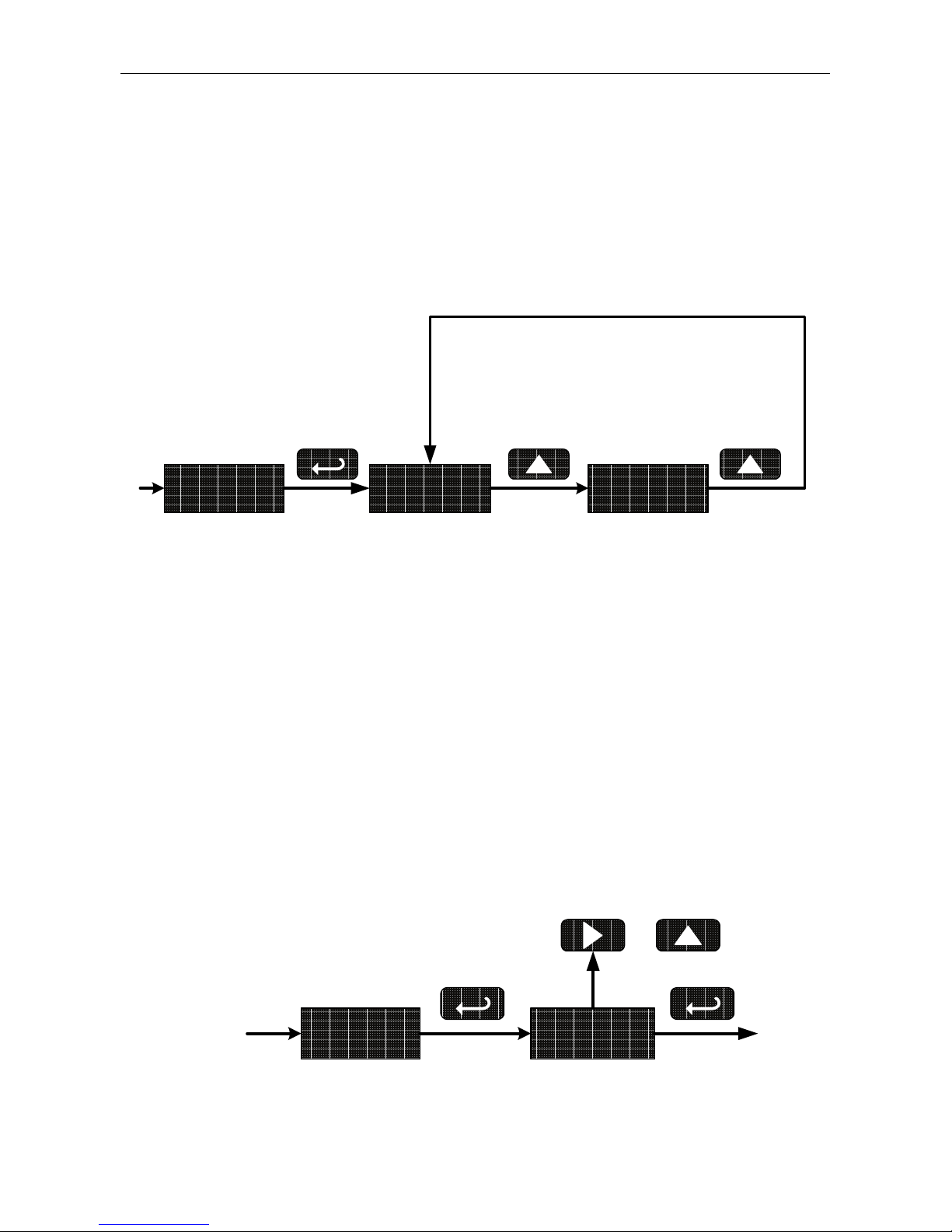
The Setup menu is used to select:
1. Decimal point position
2. Engineering units display
Press the Enter/Ack button to access any menu or press Up arrow button to scroll through choices. Press the Menu button to exit at any time.
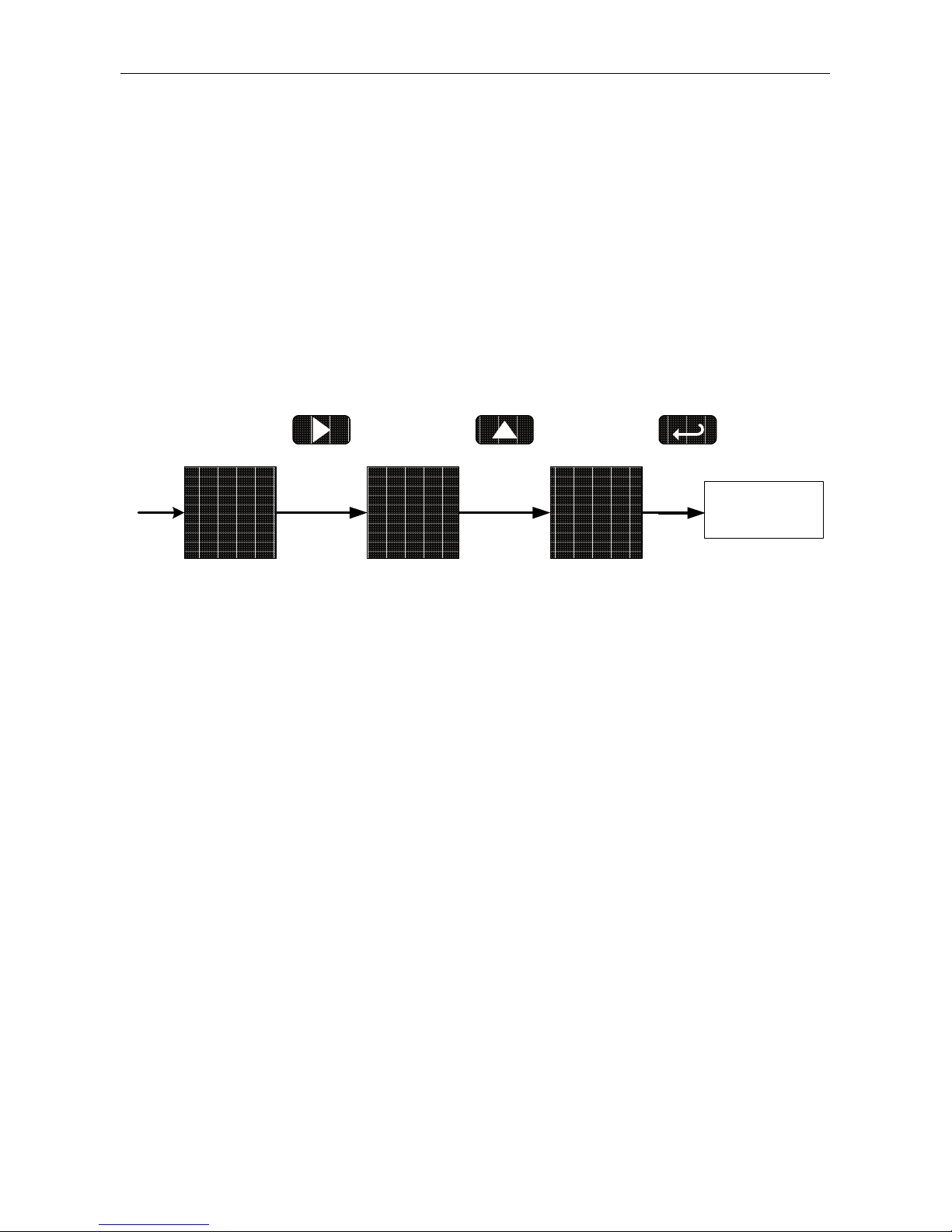
Setting the Decimal Point (deC.pt)
Decimal point may be set with up to four decimal places or with no decimal point at all.
Pressing the Right or Up arrow moves the decimal point one place to
the right until no decimal point is displayed, then it moves to the left
most position.
setuP deC.Pt
units
deC.pt
ddddd
Next
Select Decimal
Point
Previous
or
Page 17
PD683 & PD688 Loop-Powered Meters Instruction Manual
17
Setting the Units Display (units)
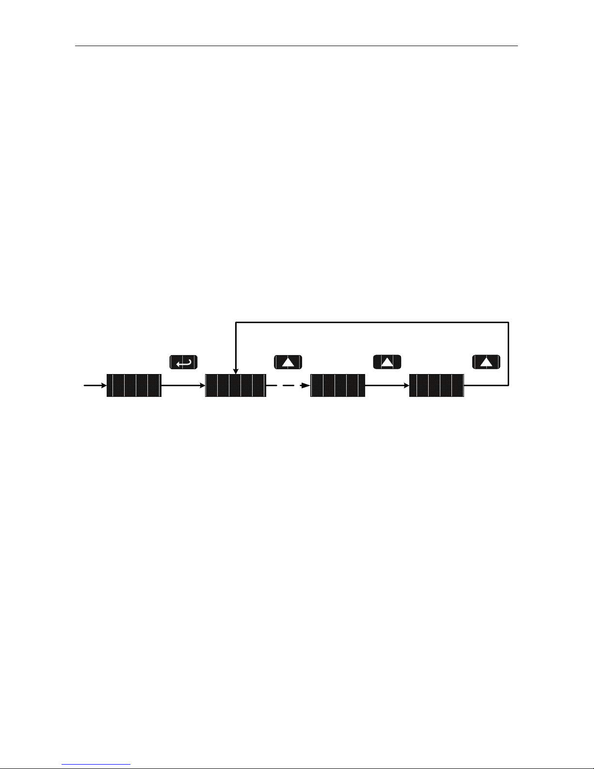
The meter can be set to display a combination of three alphanumeric
characters for engineering units or for identification (e.g. PSI, G/S, LpM,
TK3, ,L7). There is also a fourth alphanumeric character located above
this row, which supports a degrees symbol and “x10” symbol (e.g. °C,
°F,
x103, x106, x109).
Press Right arrow to select next unit and Up arrow to increment unit.
The unit being changed blinks.
Press the Enter/Ack button, at any time, to accept a setting or Menu
button to exit without saving changes.
D
aBC
Increment
Character
Next
Setting
Select Next
Character
Accept Setting
D
aBC
D
aCC
Page 18
PD683 & PD688 Loop-Powered Meters Instruction Manual
18
Programming the Meter (prog)
It is very important to read the following information, before proceeding
to program the meter:
• There is no need to recalibrate the meter for milliamps when first
received from the factory.
• The meter is factory calibrated for milliamps prior to shipment.
The calibration equipment is certified to NIST standards.
• Use the Scale menu to enter scale parameters without applying a
live signal.
• Alternatively, use the Calibrate menu to apply a signal from a cali-
brator or a 4-20 mA transmitter to calibrate the meter.
The Program menu contains the Calibrate and the Scale menus.
Inputs may be calibrated or scaled to any display within the range of the
meter.
Additional parameters, not needed for most applications, are programmed with the Advanced Features menu, see Advanced Features
Menu, page 24.
Error Message (Error)
An error message indicates that the calibration or scaling process was
not successful.
After the error message is displayed, the meter reverts to input 1, allowing the appropriate input signals to be applied.
The error message might be caused by one of the following conditions:
1. Minimum input span requirements not maintained.
2. Input 1 signal inadvertently applied to calibrate input 2.
Minimum Input Span
The minimum input span is the minimum difference between input 1 and
input 2 signals required to complete the calibration or scaling of the meter. The minimum span is 0.40 mA.
prog SCAle
CAL GrapH
Page 19
PD683 & PD688 Loop-Powered Meters Instruction Manual
19
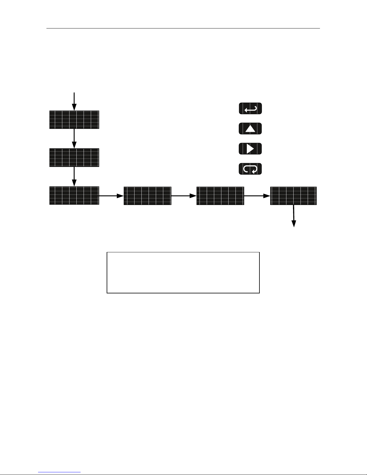
Scaling the Meter (sCalE)
The 4-20 mA input can be scaled to display the process in engineering
units.
A signal source is not needed to scale the meter; simply program the inputs and corresponding display values.
For instructions on how to program
numeric values see Setting Numeric
Values, page 15.
dsPL1
Press Enter to Accept Setting
inpt2
Scale
Input 2
inpt1
Set Input 1
Value
sCalE
04.000
Set Display 1
Value
Press Up to Set Digit Value
Press Right to Select Next Digit
Press Menu to Exit at any Time
0.0000
Page 20
PD683 & PD688 Loop-Powered Meters Instruction Manual
20
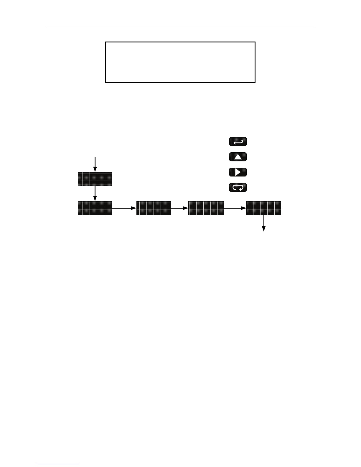
Calibrating the Meter (Cal)
To scale the meter without a signal
source, refer to Scaling the Meter
(sCalE), page 19.
The meter can be calibrated to display the process in engineering units
by applying the appropriate input signal and following the calibration
procedure.
The use of a calibrated signal source is strongly recommended.
1. Press the Up arrow button to scroll to the Calibration menu (CAL)
and press Enter/Ack.
2. The meter displays inpt1. Apply a known signal and press En-
ter/Ack. Trend arrows are displayed while accepting the signal.
3. After the signal is accepted, the meter displays dspl1. Press En-
ter/Ack, enter a corresponding display value for the signal input,
and press Enter/Ack to accept.
4. The meter displays inpt1. Apply a known signal and press En-
ter/Ack. Trend arrows are displayed while accepting the signal.
5. After the signal is accepted, the meter displays dspl2. Press En-
ter/Ack, enter a corresponding display value for the signal input,
and press Enter/Ack to accept.
Recalibrating the Internal Calibration Reference (ICal)
The Internal Calibration (ICAL) menu, located in the Advanced features
menu, is used to recalibrate the internal calibration reference. Recalibration is recommended at least every twelve months. Refer to Internal
Calibration (ICal), page 28 for instructions.
inpt1 dspl1 04.000
Set Display 1
Value
inpt2
Calibrate
Input 2
Cal
Display
Flashes
Accepting
Input
Press Enter to Accept Setting
Press Up to Set Digit Value
Press Right to Select Next Digit
Press Menu to Exit at any Time
Page 21
PD683 & PD688 Loop-Powered Meters Instruction Manual
21
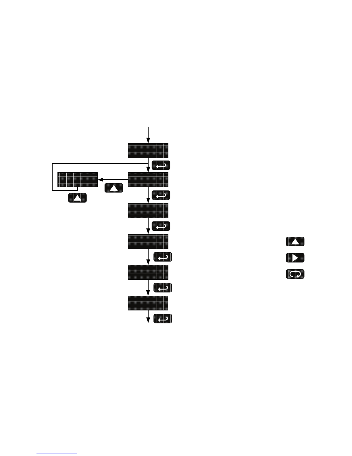
Setting Up the Bargraph (GrapH)
The meter can be set to display a bargraph proportional to the percentage process reading within a user-defined span.
The span is determined by values entered for 0% and 100%.
If the 0% and 100% values are the same as the values that were entered for display 1 and display 2, respectively, from the scale or calibrate steps, then it is not necessary to modify them.
The bargraph may be disabled by selecting OFF from the bargraph
menu.
100PCT
0PCT
Set 0%
Value
-ON-
00.000
Set 100%
Value
Press Up to Set Digit Value
Press Right to Select Next Digit
Press Menu to Exit at any Time
50.000
GrapH
-OFF-
Run Mode
Page 22
PD683 & PD688 Loop-Powered Meters Instruction Manual
22
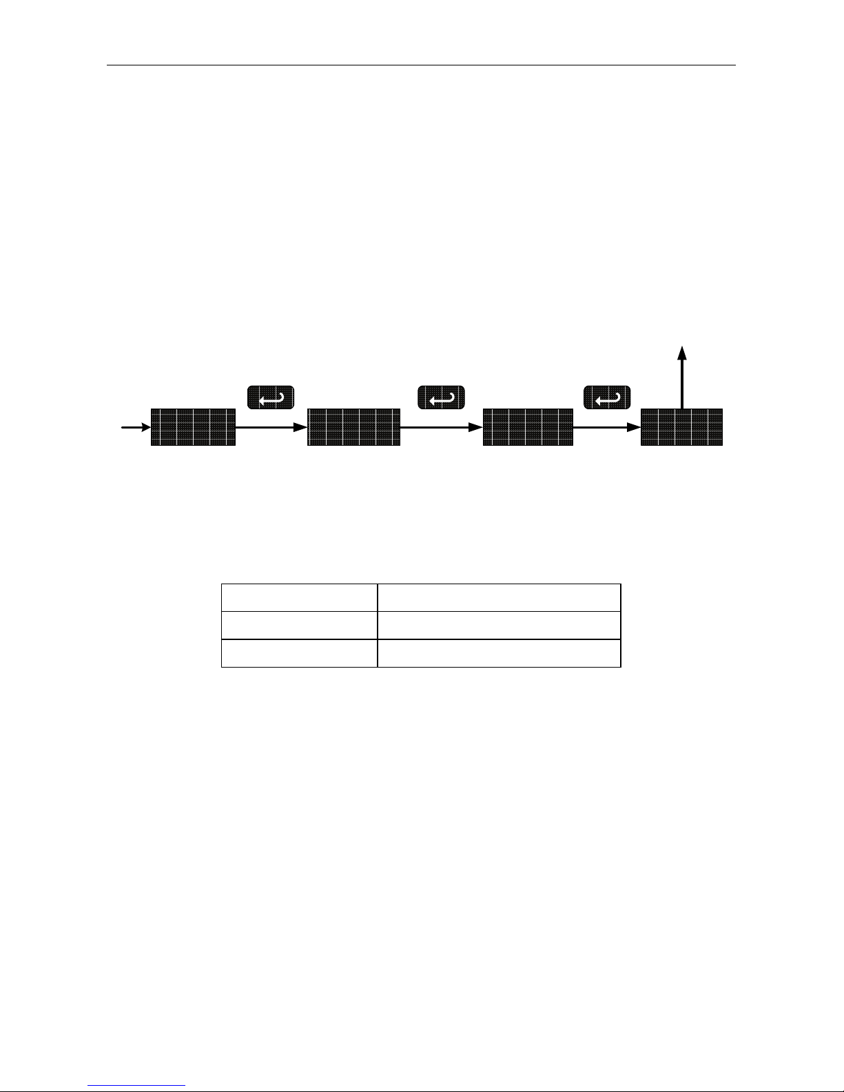
Setting Up the Password (pass)
The Password menu is used to program a five-digit password to prevent
unauthorized changes to the programmed parameter settings.
Locking the Meter
Enter the Password menu and program a five-digit password.
For instructions on how to program numeric values see Setting Numeric
Values, page 15.
Record the password for future reference. If appropriate, it may be
recorded in the space provided.
Model:
Serial Number:
Password: __ __ __ __ __
pass unloc 00000
Program
Password
locd
Run Mode
Page 23
PD683 & PD688 Loop-Powered Meters Instruction Manual
23
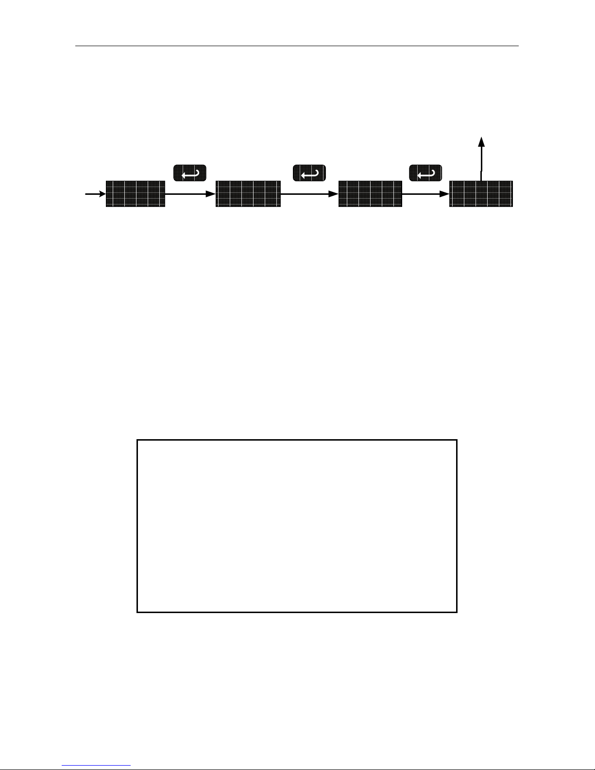
Unlocking the Meter
If the meter is password protected, the correct password must be
entered in order to make changes to the parameter settings.
Entering the correct five-digit number sets the password to 00000, disabling the protection. The meter remains unlocked until a new password
is programmed or the former password is re-programmed using the
Password menu.
Changes to the programmed parameter settings are allowed only with
the password set to 00000.
If the password entered is incorrect, the meter displays Locd (Locked)
for about three seconds, then it returns to Run Mode. To try again,
press Enter/Ack while the Locked message is displayed.
Forgot the Password?
The password may be disabled by the following
procedure:
1. Note display reading prior to pressing the Menu
button. Ignore decimal point and sign.
2. Access the
Password menu, add 2 to the noted
reading and enter that number as the password
(e.g. display reading = -1.23, password = 00125).
pass locd 00000
Enter
Password
unloc
Run Mode
Page 24
PD683 & PD688 Loop-Powered Meters Instruction Manual
24
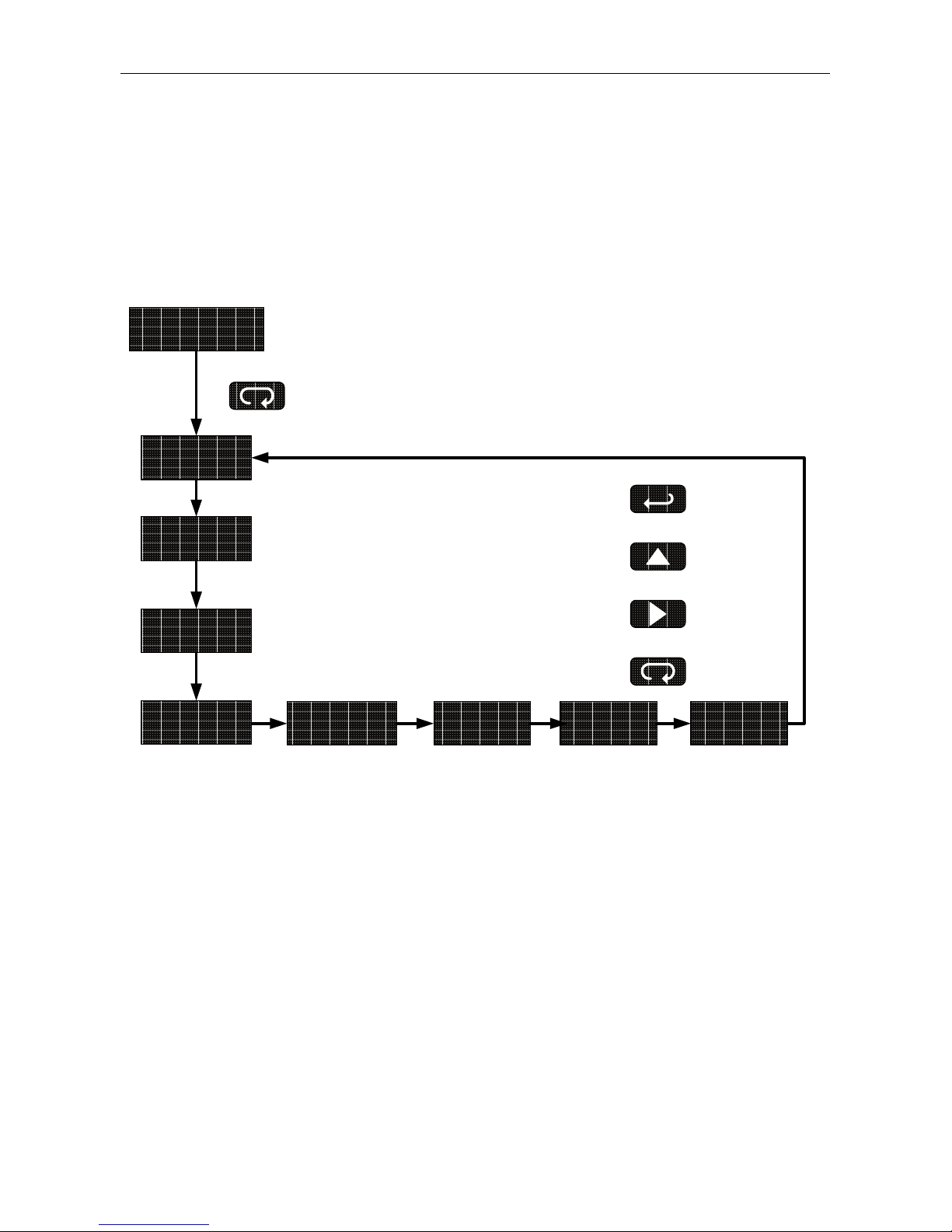
Advanced Features Menu
To simplify the setup process, functions not needed for most applications are located in the Advanced Features menu.
Press and hold the Menu button for five seconds to access the Ad-
vanced Features of the meter.
bypas
Press Enter/Ack to Access
Menu or to Accept Setting
contr
funct
flter
Press Up to Scroll Menu and
to Increment Digit Value
Press Right to Select Next Digit
Press Menu to Exit at any Time
out
Press and hold for five seconds
trend
9.2846GPS
Run Mode
I CAL info
Page 25
PD683 & PD688 Loop-Powered Meters Instruction Manual
25
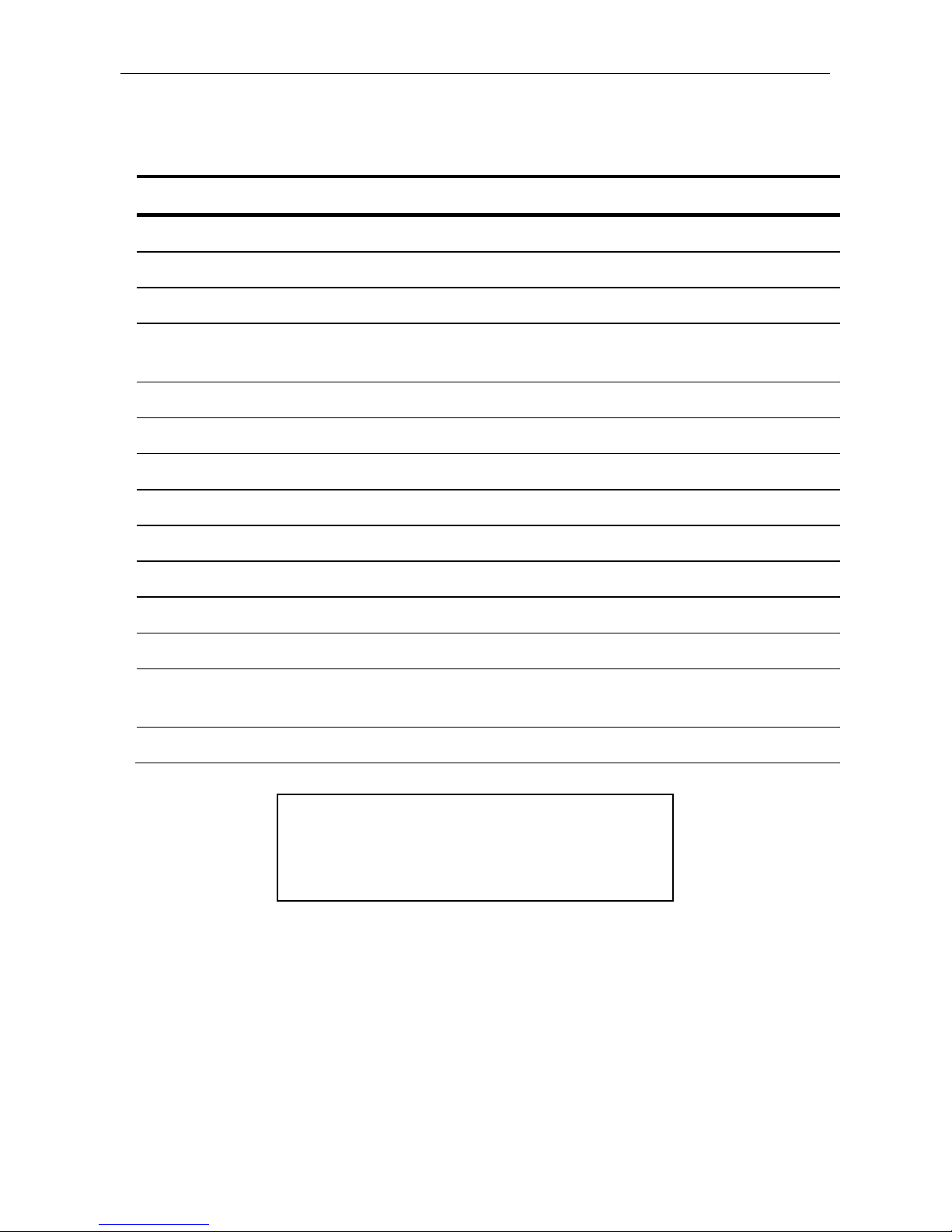
Advanced Features Menu & Display Messages
The following table shows the Advanced features menu functions and
messages in the order they appear in the menu.
Display Parameter Action/Setting
Funct
Function
Enter Function menu
Lnear
Linear
Set linear scaling
Squar
Square Root
Set square root extraction
Prog.E
Programmable
Exponent
Set programmable exponent
cutof
Low-Flow Cutoff
Set low-flow cutoff
contr
Contrast
Enter contrast adjustment menu
flter
Filter
Set noise filter value
bypas
Bypass
Set filter bypass value
Trend
Trend Arrows
Enable or disable trend arrows
-ON-
On
Enable trend arrow display
-Off-
Off
Disable trend arrow display
ICal
Initial calibration
Enter initial calibration for process inputs
Info
Meter
information
Show software number and version, or reset
to defaults
reset
Reset Defaults
Restore factory default parameter settings
For instructions on how to program
numeric values see Setting Numeric
Values, page 15.
Page 26
PD683 & PD688 Loop-Powered Meters Instruction Manual
26
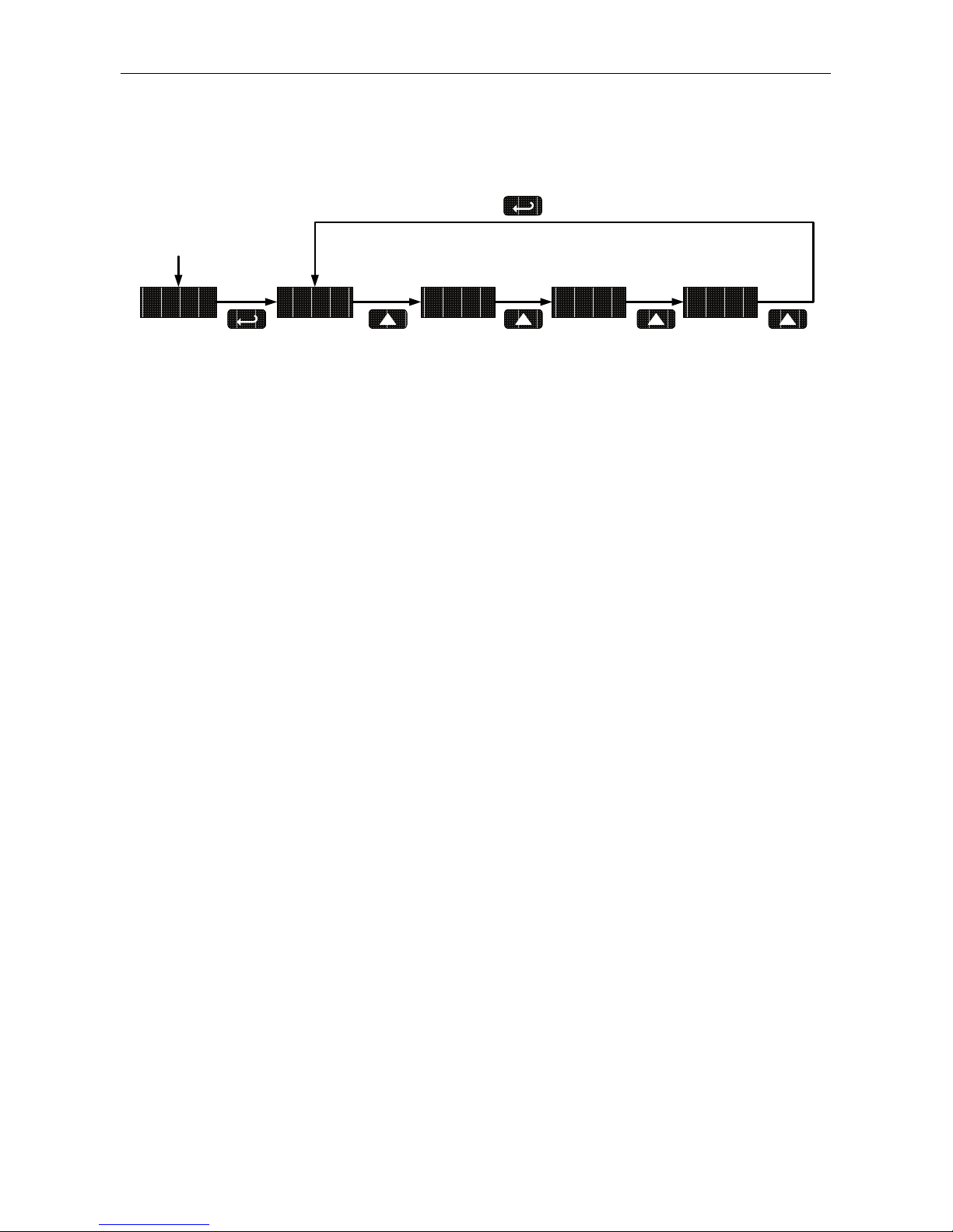
Math Functions (lnear, Squar, Prog.E, Cutof)
The PD683 & PD688 provide a number of math functions to condition
outputs from linear and non-linear transmitters.
Linear (lnear)
Meters are set up at the factory for linear function. The linear function
provides a display that is linear with respect to the input signal.
Square Root (Squar)
The square root function is used to linearize the signal from a differential
pressure transmitter and display flow rate in engineering units.
Programmable Exponent (Prog.E)
The programmable exponent function is used to linearize the level signal in applications using weirs and flumes and display flow rate in engineering units. Upon selecting programmable exponent (Prog.E), the meter prompts entry of a 5-digit value between 0.5000 and 3.0000 as the
exponent.
Low-Flow Cutoff (CutoF)
The low-flow cutoff feature allows the meter to be programmed so that
the often-unsteady output from a differential pressure transmitter, at low
flow rates, always displays zero on the meter. The cutoff value may be
programmed from -99999 to 99999. Below the cutoff value, the meter
will display zero. Selecting either square root or programmable exponent will set the cutoff value to 0. Program the cutoff value to -99999 to
disable.
LnearFunct Squar
Advanced
Features
Press Enter to Accept Setting
prog.e Cutof
Page 27

PD683 & PD688 Loop-Powered Meters Instruction Manual
27
Contrast (contr)
LCD contrast is adjustable through the front panel buttons. Select contr
and increase level using Up Arrow/Max button. Settings 1 through 9 will
be displayed on the screen as 11111 to 99999. Settings 1 through 4 are
usually best when viewing from below the angle perpendicular to the
display. Settings 5 through 9 are usually best when viewing straight on
(meter is at eye level) or when viewing from above.
Noise Filter (fltEr)
Most applications do not require changing this parameter. It is intended
to help attain a steady display with an unsteady (noisy) input signal.
The field selectable noise filter averages any minor or quick changes in
the input signal and displays the reading with greater stability.
Increasing the filter value will help stabilize the display, however this will
reduce the display response to changes on the input signal.
The filter level may be set anywhere from 1 to 199.
Noise Filter Bypass (bypAs)
The meter can be programmed to filter small input changes, but allow
larger input changes to be displayed immediately, by setting the bypass
value accordingly.
If the input signal goes beyond the bypass value, it will be displayed immediately with no averaging done on it.
The noise filter bypass value may be set anywhere from 0.2 to 99.9. It
corresponds to percentage of full scale.
Increasing the bypass value may slow down the display response to
changes on the input signal.
Pressing the Right Arrow/Reset button will also bypass the filter and
provide an instant update.
Page 28
PD683 & PD688 Loop-Powered Meters Instruction Manual
28
Internal Calibration (ICal)
• There is no need to recalibrate the meter for
milliamps when first received from the factory.
• The meter is factory calibrated for milliamps
prior to shipment. The calibration equipment is
certified to NIST standards.
The internal calibration allows the user to scale the meter without applying a signal. The use of a calibrated signal source is necessary to perform the internal calibration of the meter. Check calibration of the meter
at least every 12 months.
Notes:
• The signal source must have a full-scale accuracy
of 0.01% or better between 4 and 20 mA in order
to maintain the specified accuracy of the PD688.
• Allow the meter to warm up for at least
15 minutes before performing the internal calibration procedure.
The Internal calibration menu is part of the Advanced features menu.
1. Press and hold the Menu button for five seconds to access the Advanced Features of the meter.
2. Press the Up arrow button to scroll to the Internal calibration menu
(ICAL) and press Enter/Ack.
3. The meter displays 4.000 mA. Apply a 4.000 mA signal and press
Enter/Ack. The display shows both trend arrows for a moment
while the meter is accepting the signal.
4. After the signal is accepted, the meter displays 8.000 mA. Apply an
8.000 mA signal and press Enter/Ack. The display shows both
trend arrows for a moment while the meter is accepting the signal.
5. Continue, as in the previous step, for the remaining signals:
12.000 mA, 16.000 mA, and 20.000 mA.
Error Message (Error)
An error message indicates that the calibration or scaling process was
not successful. After the error message is displayed, the meter reverts
to the previous signal prompt, allowing the appropriate input signal to be
applied. The error message might be caused by inadvertently leaving
the signal at the previous level.
Page 29

PD683 & PD688 Loop-Powered Meters Instruction Manual
29
Information Menu (info)
The Information menu is located in the Advanced features menu, to access Information menu see Advanced Features Menu, page 24.
It shows software and version number. To determine the software version of a meter:
1. Go to the Information menu (info) and press Enter/Ack but-
ton. The number shown is the software number.
2. Press Enter/Ack again to display the release version.
Page 30
PD683 & PD688 Loop-Powered Meters Instruction Manual
30
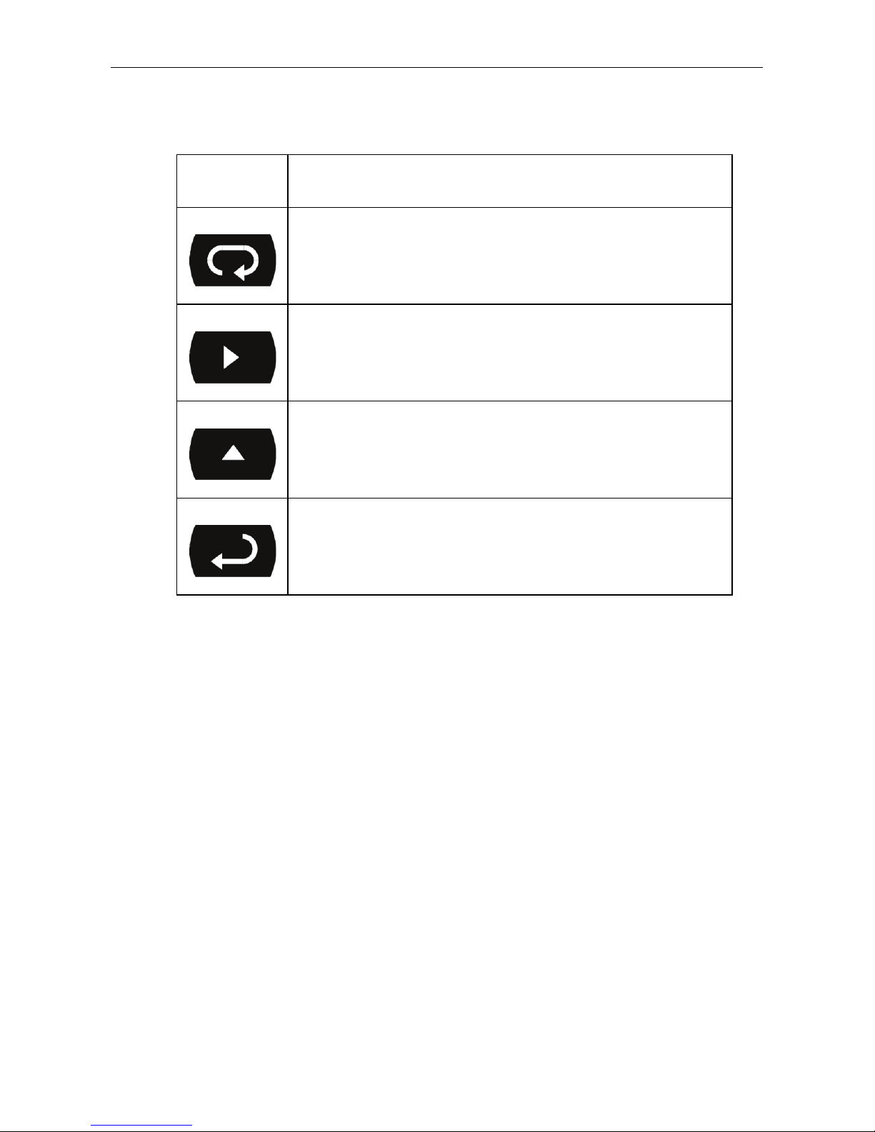
OPERATION
Front Panel Buttons Operation
Button
Symbol
Description
Press to enter or exit Programming Mode,
view settings, or exit Max/Min readings
Press to reset Max/Min readings
Press to manually bypass filtering
Press to display Max/Min readings
alternately
Press to display Max/Min reading
indefinitely while displaying Max/Min
Press ACK to acknowledge trend arrows
Page 31
PD683 & PD688 Loop-Powered Meters Instruction Manual
31
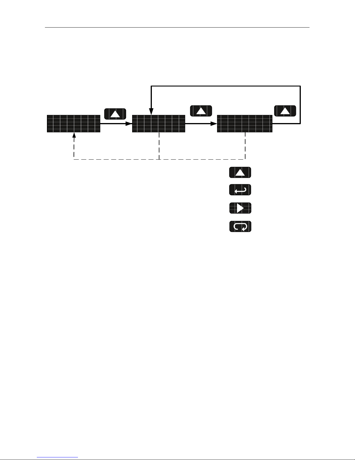
Maximum & Minimum Readings (Max& MiN)
The maximum and minimum (peak & valley) readings reached by the process are stored in the meter since the last reset or power-up. The meter
shows MIN or MAX to differentiate between run mode and max/min display.
1. Press Up arrow/Max button to display maximum reading since the
last reset/power-up.
2. Press Up arrow/Max again to display the minimum reading since
the last reset/power-up.
3. Press Enter/Ack to hold Max/Min display reading, the meter will
continue to track new Max/Min readings.
4. If Enter/Ack is not pressed, the Max/Min display reading will time
out after ten seconds and the meter will return to display the actual
reading.
5. Press Right arrow/Reset button to reset Max/Min while reading is
being displayed. Max/Min display readings are reset to actual
reading.
Press Up to Display and to
Toggle Between Max & Min
10 Sec Time Out
9.2846GPS
Run Mode
9.5320MAX
6.1391MIN
Press Enter to hold Max/Min
Press Right to Reset Max/Min
Press Menu to Exit Max/Min
Page 32
PD683 & PD688 Loop-Powered Meters Instruction Manual
32
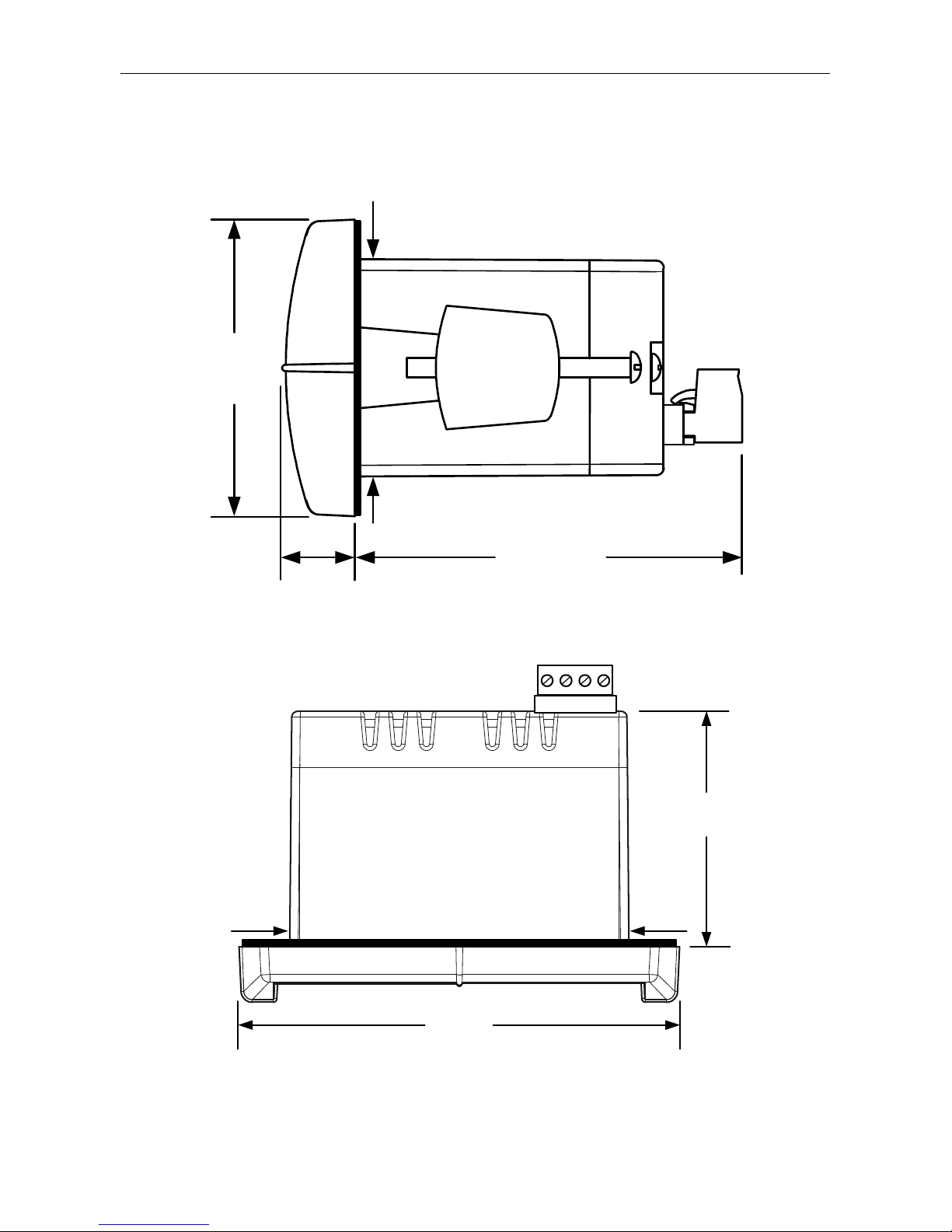
MOUNTING DIMENSIONS
Figure 5. Meter Dimensions – Side View
Figure 6. Case Dimensions – Top View
1.76"
(45mm)
0.59"
(15mm)
3.2"
(81mm)
2.45"
(62mm)
3.61"
(92mm)
2.50"
(64mm)
4.68"
(119mm)
Page 33
PD683 & PD688 Loop-Powered Meters Instruction Manual
33
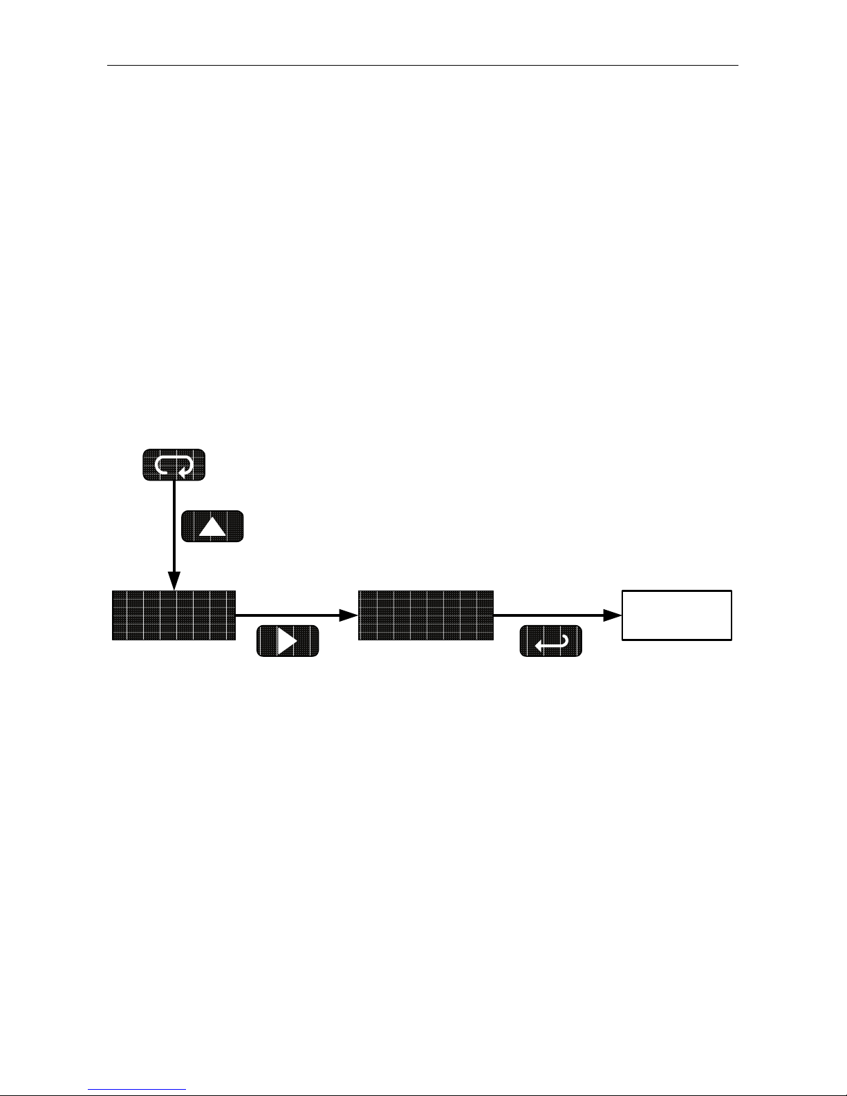
Reset Meter to Factory Defaults
When the parameters have been changed in a way that is difficult to determine what’s happening, it might be better to start the setup process
from the factory defaults.
Instructions to load factory defaults:
1. Enter the Advanced features menu. See Advanced Features Menu,
page 24.
2. Press Up arrow until info is shown.
3. Press and hold Right arrow/Reset for five seconds, press
Enter/Ack when display flashes reset.
Note: If Enter/Ack is not pressed within three seconds, display returns to Information menu.
4. The meter goes through an initialization sequence (same as on
power-up), and loads the factory default settings.
reset
info
Press and Hold for 5 Sec
Meter Re-
Initializes
Press and Hold
for 3 Sec
Flashing
Display
Page 34
PD683 & PD688 Loop-Powered Meters Instruction Manual
34
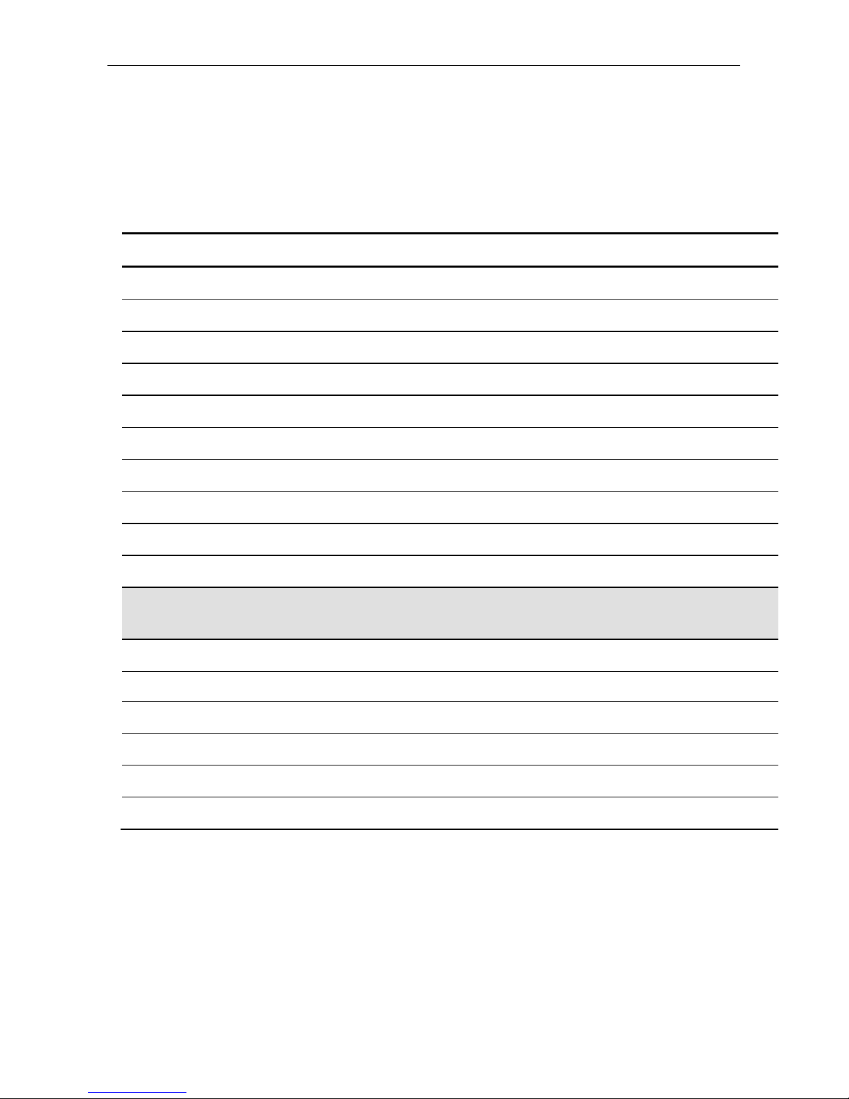
Factory Defaults & User Settings
The following table shows the factory setting for most of the programmable parameters on the meter. Next to the factory setting, the user
may record the new setting for the particular application.
Model: ______________ S/N: _______________ Date: _________
Parameter Display Default Setting User Setting
Programming
prog
Scale
Input 1
inPt1
4.000 mA
Display 1
Dspl1
4.000
Input 2
inPt2
20.00 mA
Display 2
Dspl2
20.000
Decimal point
Dd.ddd
3 places
Bargraph
GrapH
On (enabled)
Bargraph 0%
0 PCT
4.000
Bargraph 100%
100 PCT
20.000
Password
pass
00000 (unlocked)
Advanced
Features
Function
Funct
Linear
Contrast
contr
5 (55555)
Cutoff
Cutof
-99999 (disabled)
Filter
Flter
1
Bypass
Bypas
0.2
Trend Arrows
Trend
On (enabled)
Page 35
PD683 & PD688 Loop-Powered Meters Instruction Manual
35
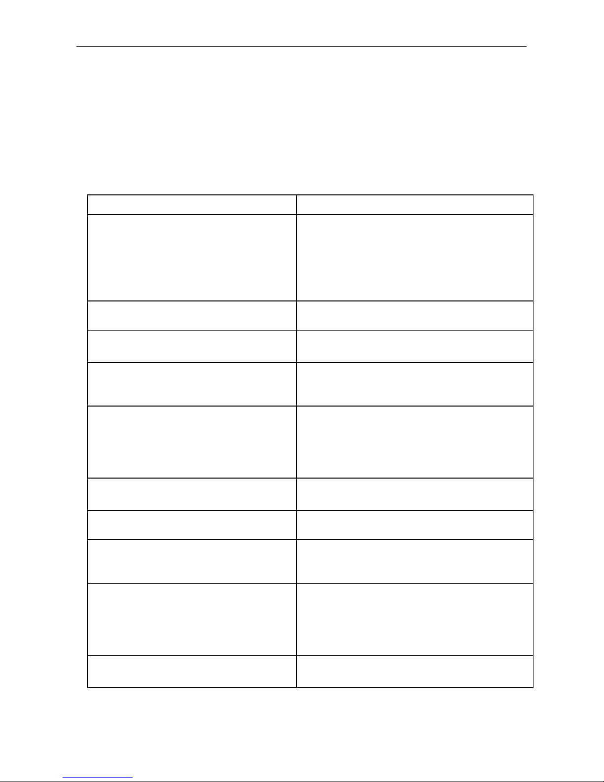
TROUBLESHOOTING
The rugged design and the user-friendly interface of the meter should
make it unusual for the installer or operator to refer to this section of the
manual.
If the meter is not working as expected, refer to the recommendations
below.
Troubleshooting Tips
Symptom Check/Action
No display or faint display
1. Check connections.
2. Increase contrast setting in
Advanced menu.
3. Perform hard reset by temporarily
shorting S+ and S- terminals for a
few seconds.
Rate display unsteady
Increase filter setting in
Advanced
menu.
Not able to change setup or programming,
Locd is displayed
Meter is locked, enter correct five-digit
password to unlock.
Meter displays error message during calibration (
error)
Check:
1. Signal connections
2. Minimum input span requirements
Meter displays
• 99999
• -99999
Check:
1. Input signal within range.
2. When using square root or programmable exponent, cutoff must
be zero or greater.
Display stuck showing a number
and
MAX or MIN
Press
Menu to exit Max/Min
display readings.
Display response is too slow
Check filter and bypass values to see if
they can be lowered.
If the display locks up or the meter
does not respond at all
Perform hard reset by temporarily shorting S+ and S- terminals for a few seconds and then removing short.
Display shows blurry, hard-to-read
digits in below freezing temperatures (less than -18°C or 0°F).
Increase the filter setting to 10 or
greater and the bypass setting to 50 or
greater. This will slow the display response rate, but digits will be steady
and appear more clearly.
Other symptoms not described
above
Call Technical Support for
assistance.
Page 36
PD683 & PD688 Loop-Powered Meters Instruction Manual
36
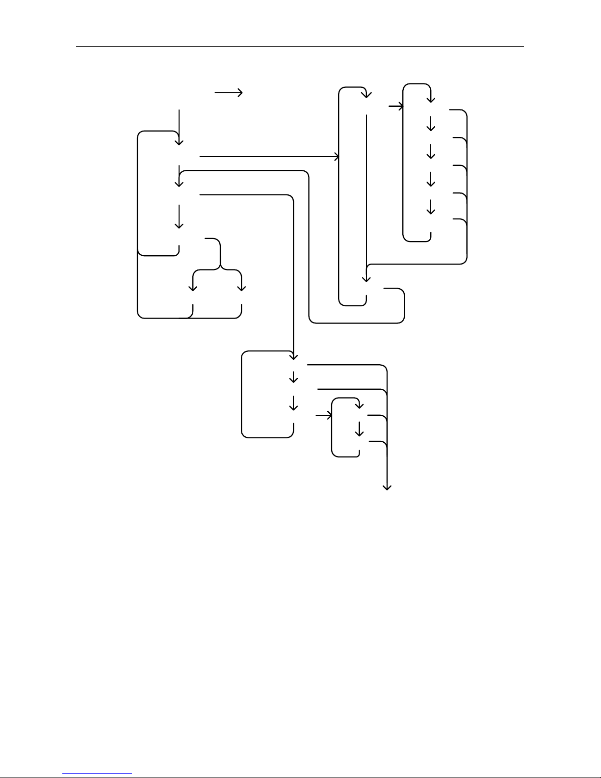
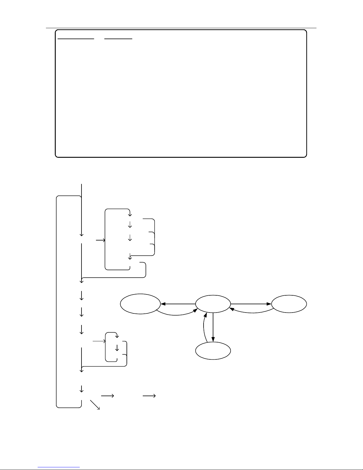
QUICK USER INTERFACE REFERENCE GUIDE
Run Mode
Setup
Program
Password
Display
Max/Min
Decimal
ddddd
d . dddd
dd . ddd
ddd . dd
Locked Unlocked
Bargraph
Calibrate
To Password
dddd . d
Scale
Units
On
Off
Page 37
PD683 & PD688 Loop-Powered Meters Instruction Manual
37
*Access by holding Right/Reset for 3 seconds
Pushbutton Function
Menu Go to Programming Mode or leave Programming, Advanced
Features, and Max/Min Modes.
Right Arrow Move to next digit or decimal point position. Reset Total.
Up Arrow Move to next selection or increment digit. Go to Max/Min Mode.
Enter/Ack Accept selection/value and move to next selection. Toggle Rate/
Total.
Hold to Acknowledge Alarm.
Menu held for 5 seconds enters Advanced Features
Max/Min Mode
While in Run Mode, pressing Up Arrow will initiate Max/Min Mode. Up Arrow toggles
between Max & Min displays, and Right Arrow resets the Max/Min to the current
value. Press Menu or wait 10 seconds to return to Run Mode. Pressing Enter/Ack will
disable the 10 second timeout and continuously display Max or Min.
Press & hold Menu for 5
seconds to access Advanced
Features Menu
When a password is enabled,
parameter settings are locked, but
scale settings can be displayed by
selecting the program menu.
Program
Run
Max &
Min
Advanced
Features
Up Arrow
Menu
Menu
Menu
Menu
Operational Modes
Function
Filter
Bypass
Trend
Arrows
Initial
Calibrate
Information
Menu for 5
seconds
Linear
Square Root
Programmable
Exponent
Cutoff
On
Off
Software
Version
*Factory
Defaults
Contrast
Page 38
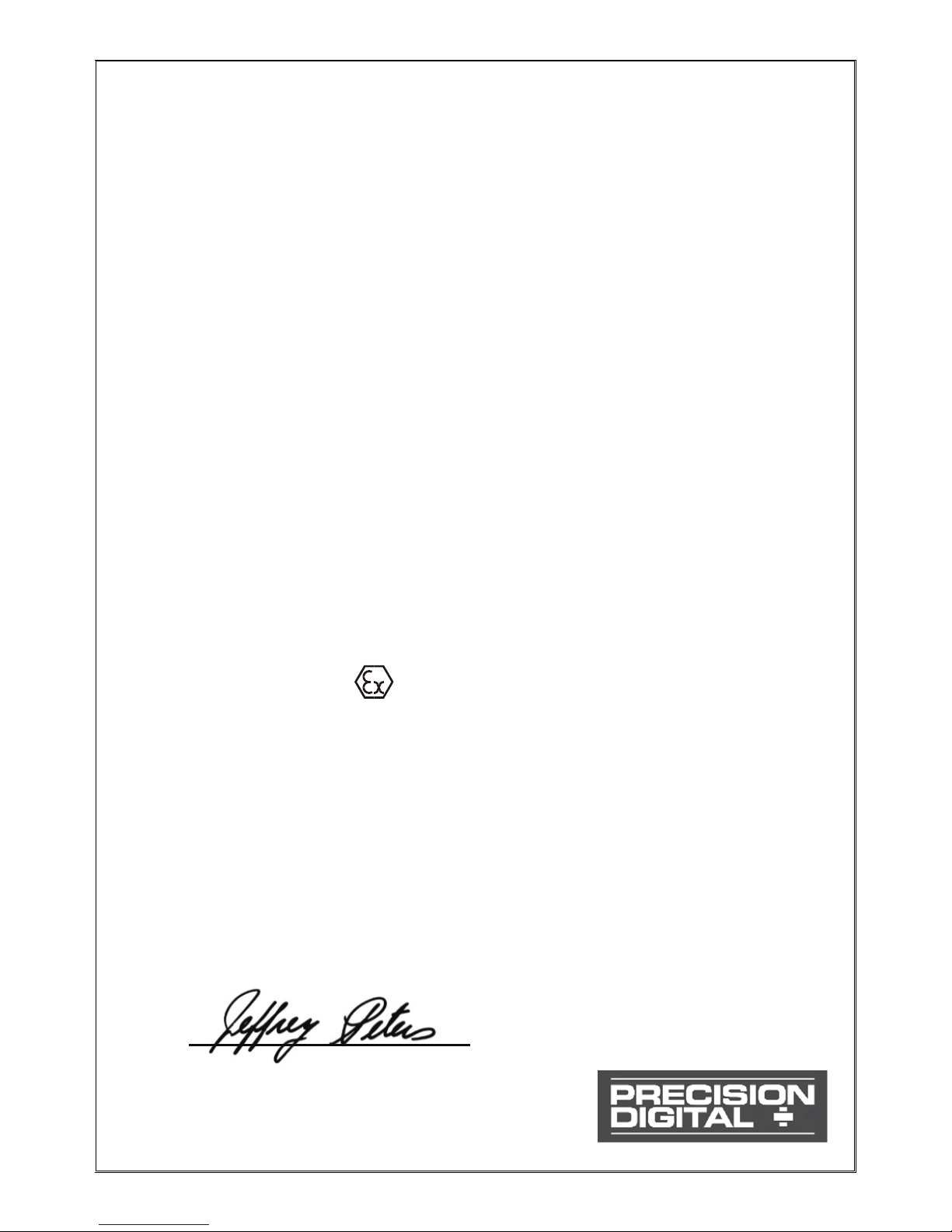
EU DECLARATION OF CONFORMITY FOR PD688
Issued in accordance with ISO/IEC 17050-1:2004 and ATEX Directive 2014/34/EU.
We,
Precision Digital Corporation
233 South Street
Hopkinton, MA 01748 USA
as the manufacturer, declare under our sole responsibility that the product(s),
Model PD688 Loop Powered Panel Meter
to which this declaration relates, is in conformity with the European Union Directives shown
below:
2014/35/EU Low Voltage Directive
2014/34/EU ATEX Directive
2014/30/EU EMC Directive
2011/65/EU RoHS Directive
This conformity is based on compliance with the application of harmonized or applicable
technical standards and, when applicable or required, a European Union notified body
certification.
Standards:
EN 60079-0:2006 EN 60079-11:2007 EN 60079-26:2007
EN 61010-1:1995 EN 61326:2006
The standards EN 60079-0:2006, EN 60079-11:2007, EN 60079-26:2007, EN 610101:1995, and EN 61326:2006 are no longer harmonized. The requirements of these
standards have been checked against the harmonized standard EN 600790:2012+A11:2013, EN 60079-11:2012, EN 60079-26:2015, EN 61010-11:2010, and EN
61326:2013 and there were no major technical changes affecting the latest technical
knowledge for the products listed above.
EC Type Examination Certificate: FM08ATEX0058X
Product Markings: II 1 G
Ex ia IIC T4
Tamb = -40°C to +65°C
ATEX Notified Body for EC Type Examination Certificate:
FM Approvals Ltd., NB 1725
1 Windsor Dials
Windsor, Berkshire, SL4 1RS, UK
ATEX Quality Assurance Notification No.:
SIRA 10 ATEX M462
ATEX Notified Body for Quality Assurance:
Sira Certification Service, NB 0518
Rake Lane
Eccleston, Chester, CH4 9JN, UK
Signed for and on behalf of Precision Digital Corporation:
Name: Jeffrey Peters
Company: Precision Digital Corporation
Title: President
Date: 04/20/2016
Document No: DoC PD688 {042016}
Page 39
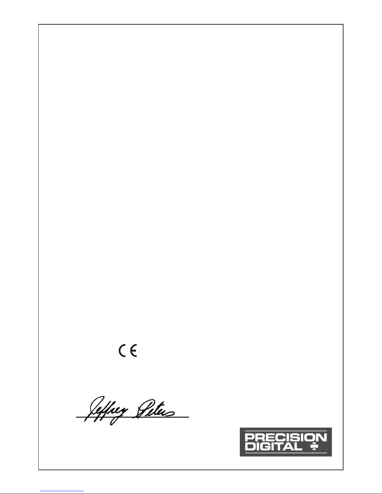
EU DECLARATION OF CONFORMITY FOR PD683
Issued in accordance with ISO/IEC 17050-1:2004.
We,
Precision Digital Corporation
233 South Street
Hopkinton, MA 01748 USA
as the manufacturer, declare under our sole responsibility that the product(s),
Model PD683 Loop Powered Panel Meter
to which this declaration relates, is in conformity with the European Union Directives shown
below:
2014/35/EU Low Voltage Directive
2014/30/EU EMC Directive
2011/65/EU RoHS Directive
This conformity is based on compliance with the application of harmonized or applicable
technical standards and, when applicable or required, a European Union notified body
certification.
Standards:
EN 60079-0:2006
EN 60079-11:2007
EN 60079-26:2007
EN 61010-1:1995
EN 61326:2006
The standards EN 60079-0:2006, EN 60079-11:2007, EN 60079-26:2007, EN 610101:1995, and EN 61326:2006 are no longer harmonized. The requirements of these
standards have been checked against the harmonized standard EN 600790:2012+A11:2013, EN 60079-11:2012, EN 60079-26:2015, EN 61010-11:2010, and EN
61326:2013 and there were no major technical changes affecting the latest technical
knowledge for the products listed above.
Product Markings:
Signed for and on behalf of Precision Digital Corporation:
Name: Jeffrey Peters
Company: Precision Digital Corporation
Title: President
Date: 04/20/2016
Document No: DoC PD683 {042016}
Page 40

PD683 & PD688 Loop-Powered Meters Instruction Manual
LIM688_K
SFT037 Ver 1.210 & up
04/16
How to Contact Precision Digital
• For Technical Support:
Call: (800) 610-5239 or (508) 655-7300
Fax: (508) 655-8990
Email: [email protected]
• For Sales Support:
Call: (800) 343-1001 or (508) 655-7300
Fax: (508) 655-8990
Email: [email protected]
• For the latest version of this manual please visit:
www.predig.com
 Loading...