

Page 1

Multiport (3-way)
Plug Valve
Operation and
Maintenance Manual
Series 604
INSTALLATION/OPERATING MANUAL
TABLE OF CONTENTS PAGE
Design and Function 2
Safety 3
Installation 4
Standard Materials of Construction 5
"U" Cup Seal Replacement 6
Plug to Seat Adjustment 7
Disassembly and Reassembly 8
Plug Replacement 9
Lubrication and Spare Parts List 10
Plug Valve Port Positions 11
Troubleshooting 12
3"-16" Three-Way Plug Valves 13
WARNING:
1. Read all applicable directions and instructions prior to any maintenance,
troubleshooting or installation.
2. Personnel involved in the installation or maintenance of valves should be constantly
alert to potential emission of pipeline material and take appropriate safety
precautions. Always wear suitable protection when dealing with hazardous pipeline
materials.
3. Order parts from your local Pratt sales representative or directly from Pratt.
When ordering parts, please include the serial number located on the valve tag.
NOTE: “WARNING” and “CAUTION” messages (agged with an exclamation symbol)
indicate procedures that must be followed exactly to avoid equipment damage,
physical injury, or death.
F14237 1/20
Page 2

MULTIPORT (3-WAY) PLUG VALVE OPERATION AND
MAINTENANCE MANUAL SERIES 604
Design and Function
DESIGN AND FUNCTION
The Multiport valve is a non-lubricated plug valve designed for diverting applications and are use in water
and wastewater applications, and HVAC systems. The valve is a anged 3-way design with a rubber encapsulated
taper plug. The straight through or 90º ow paths allow a plug rotation up to 270º in increments of 90º.
Wrench operated valves may be factory set for the plug/port positioning by the inclusion of a styling ring.
Valves tted with gear operators will have the travel stops factory set when customers specify the particular
port selections at ordering stage.
The life of the valve is dependent on its application, frequency of use and freedom from misuse. The properties
of the uid passing through the valve such as pressure, temperature, chemical constituents and solids content
must be taken into consideration to avoid premature failure. A well-designed system will take into consideration
additional factors such as the electrolytic interaction between dissimilar metals in the valve and pipework.
Before commissioning a system, it should be ushed to eliminate debris and chemically cleaned as appropriate
which will help prolong the life of the valve. Not suitable for fatigue loading, creep conditions, re testing,
re hazard environment, corrosive or erosive service, transporting uids with abrasive solids.
PRESSURE AND TEMPERATURE LIMITS
These valves must be installed in a piping system whose normal pressure and temperature do not exceed the ratings
shown below. If system testing will subject the valve to pressures in excess of the working pressure rating, this should
be within the test pressure for the body, with the valve partially open. The maximum allowable pressure is for non-shock
conditions. Water hammer and impact for example, should be avoided.
If the limits of use specied in these instructions are exceeded or if the valve is used on applications for which it was
not designed, a potential hazard could result. The operating temperature of the valve may depend on the elastomer
used for the plug and seals and are as follows.
Elastomer High Temp Low Temp
Buna N 212°F -20°F
EPDM 250°F -20°F
Neoprene 225°F -20°F
Viton 300°F -10°F
Figure 604 Multiport 3-way plug valves are provided with ANSI Class 125 Flanges.
Size Range Rated Pressure* Shell Hydro Seat Test **
3”-16” 175 psi 265 psi 175 psi
*Pressure rating is given at ambient temperatures
**3-way Plug Valves DO NOT offer drip tight shutoff
2
Page 3

MULTIPORT (3-WAY) PLUG VALVE OPERATION AND
MAINTENANCE MANUAL SERIES 604
SAFETY
Personnel involved with the installation or maintenance of these valves should be aware of the potential
hazards involved with the handling and installation of valves. Appropriate safety precautions should be taken
prior to maintenance work commencing particularly in respect to possible emissions or leakage of pipeline
uids. The Maintenance Engineer must be skilled and fully aware of the nature of the pipeline uid and the
system operating conditions.
Suitable protection should be worn - particularly appropriate footwear, hard hats and gloves. During
maintenance work, eye and respiratory protection may also be necessary. There are no hazardous materials
used in the construction of the valve. Valves must be de-pressurized before any disassembly procedures
are performed.
On gear operated valves, when the gears have the cover removed, extra caution should be taken to make
sure hands or ngers are away from the moving parts. Close tting clothing should be worn so as to avoid
getting caught in the moving gears.
Safety
RECEIVING AND STORAGE
Inspect the valves upon receipt for damage during shipment. Valves must be carefully unloaded. Do not lift valves
with slings or chains through the seat area or attached to hand-wheels or actuators.
Henry Pratt valves are shipped with the plugs in the open position. Care should be taken to maintain this position
while the valves are in storage prior to installation in the pipeline.
Flanged valve end protectors (if supplied) should be kept on the valves until they are ready for installation. Valves
should be kept in clean and dry storage facility and protected against the ingress of debris. Care should be taken to
avoid direct sunlight or exposure to heat on the plug elastomer during storage.
Electric, hydraulic and pneumatic valve actuators should be care for in accordance with the storage instructions of
the actuator manufacturer.
3
Page 4
MULTIPORT (3-WAY) PLUG VALVE OPERATION AND
MAINTENANCE MANUAL SERIES 604
Installation
INSTALLATION
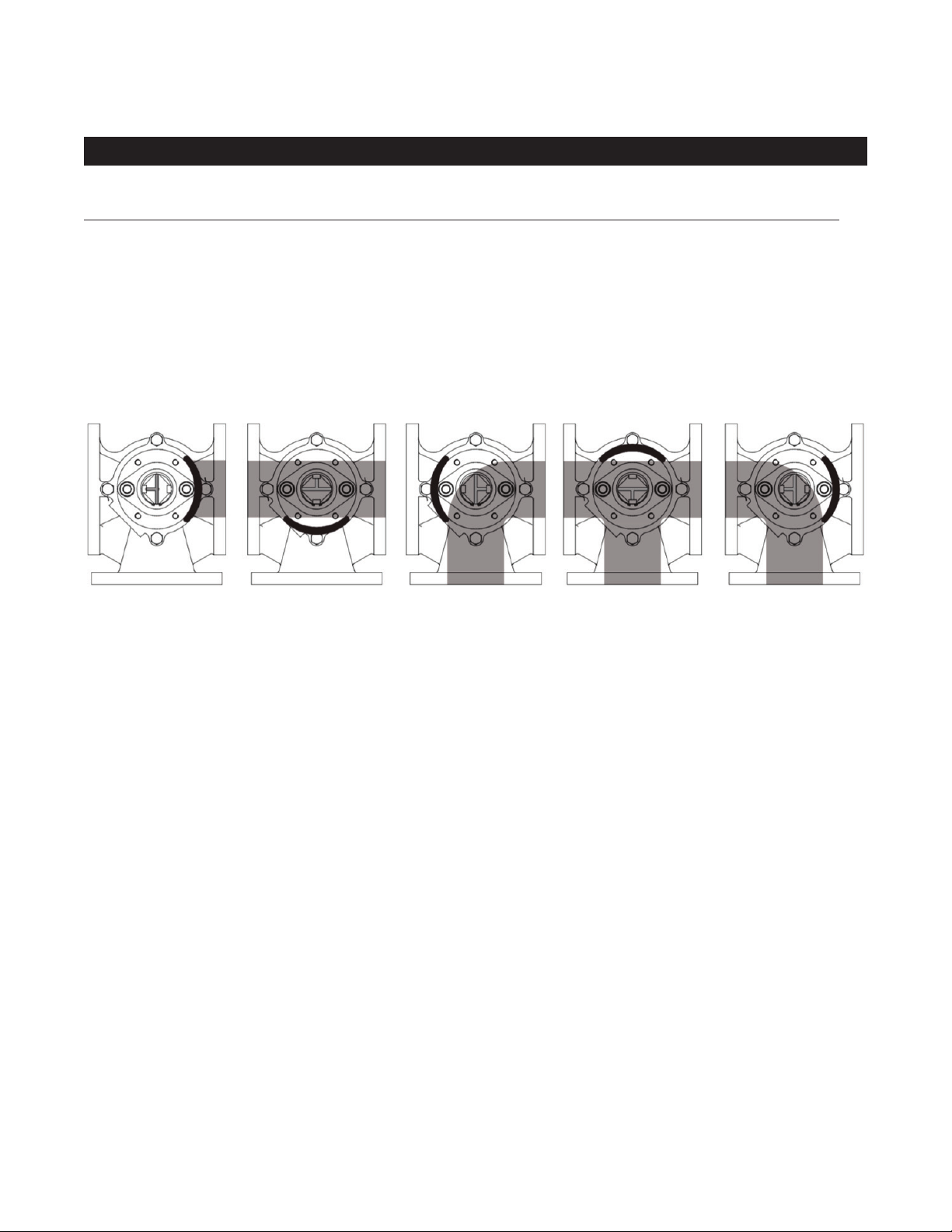
The Pratt® Multi-Port 3-way plug valve can be installed in any orientation although it is advisable to have the valve
stem vertical for ease of access. If the valve has been supplied for tight shut-off, the ow path and therefore the
upstream pressure should be against the rear side of the plug (see Fig.1). The valve is suitable for ow in any
direction although it is recommended that the valve is installed with pipeline pressure applied behind the plug with
the plug face in the downstream position.
Valves must be provided with adequate support. Adjoining pipework must be supported to avoid the imposition of
pipeline strains on the valve body. Heavy valves may need independent support or anchorage.
FIG. 1: AVAILABLE FOW PATHS
VALVE IN CLOSED
POSITION*
*
It is advisable that the ow is against the rear side of the plug for tight shut-off applications. Not available with double-style plug.
Prior to installation, inspection of the body marking must be made to ensure that the correct valve is being installed.
Valves are precision manufactured items and should not be subjected to misuse such as:
• Careless handling
• Allowing dirt to enter the valve through the end ports
• Lack of cleaning both valve and system before operation
• Excessive force during bolting.
When large valves are provided with lifting lugs or eye bolts, these should be used to lift the valve. Immediately prior to
valve installation, the pipework to which the valve is to be fastened should be checked for cleanliness and freedom from
debris. All special packaging material must be removed.
The mating ange (both valve and pipework anges) should be checked for correct gasket contact face, surface
nish and condition. If a condition is found which might cause leakage, no attempt to install the valve should be made
until the condition has been corrected. The gaskets should be suitable for the operating conditions and maximum
pressure/temperature ratings and should be checked to ensure freedom from defects or damage.
Care should be taken to provide correct alignment of the anges being assembled. Suitable lubricant on bolt threads
should be used. In assembly, bolts are tightened sequentially to make the initial contact of anges and gaskets
followed by gradual and uniform tightening in an opposite bolting sequence to avoid bending one ange relative to the
other, particularly on anges with raised faces. Parallel alignment of anges is especially important in the case of the
assembly of a valve into an existing system. The bolting must be checked for correct size, length, material and that all
connection ange bolt holes are utilized.
FLOW STRAIGHT
THROUGH VALVE
FLOW THROUGH
90˚ TO SIDE PORT
ALL 3 PORTS
CONNECTED AND OPEN
FLOW THROUGH
90˚ TO SIDE PORT
Certain sizes of valves have tapped bolt holes in the connecting anges where there is no room for nuts behind the
ange, refer to drawings on pages 13 - 15.
4
Page 5
MULTIPORT (3-WAY) PLUG VALVE OPERATION AND
MAINTENANCE MANUAL SERIES 604
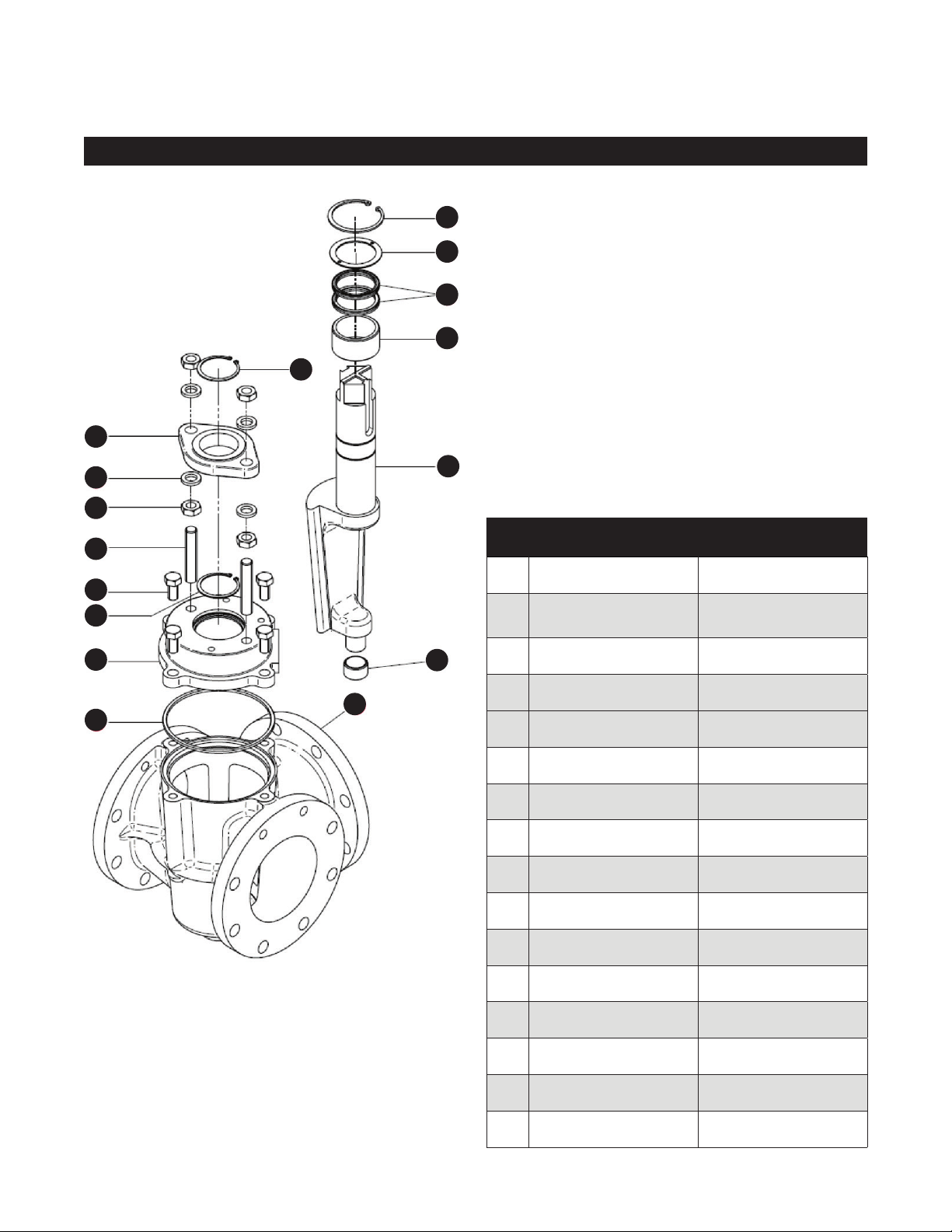
Standard Materials of Construction
16
15
14
13
11
10
9
8
7
2
Item Component Material
1 Body Cast Iron A126 Class B
5
6
4
1
3
12
2 Plug
3 Bonnet O-Ring Elastomer as Specied
4 Bonnet Cast Iron A126 Class B
5 Setscrew Steel - Zinc Plated
Ductile Iron ASTM
A536 Rubber Coated
6 Snap Ring -Internal Steel
7 Stud Steel - Zinc Plated
8 Nut Steel - Zinc Plated
9 Washer Steel - Zinc Plated
10 Gland Ductile Iron ASTM A536
11 Snap ring - Internal Steel
12 Journal Bearing Stainless Steel
13 Journal Bearing Stainless Steel
14 "U" Cup Seal Elastomer as Specied
15 Seal Retaining Ring Brass
16 Snap ring - External Steel
5
Page 6
MULTIPORT (3-WAY) PLUG VALVE OPERATION AND
MAINTENANCE MANUAL SERIES 604
Replace "U" Cup Seals
REPLACE “U” CUP SEALS
The Multiport is designed and manufactured to be a long life valve under normal operating conditions. It does not
require any routine maintenance. Cycling the valve from fully open to fully closed on an annual basis will increase
the life of the valve and actuator components.
However, if maintenance is required, due to unusual wear or service conditions, the following procedure
should be followed:
1. Remove nuts on top of plug adjustment gland.
2. Remove external snap ring from top of gland.
3. Remove gland.
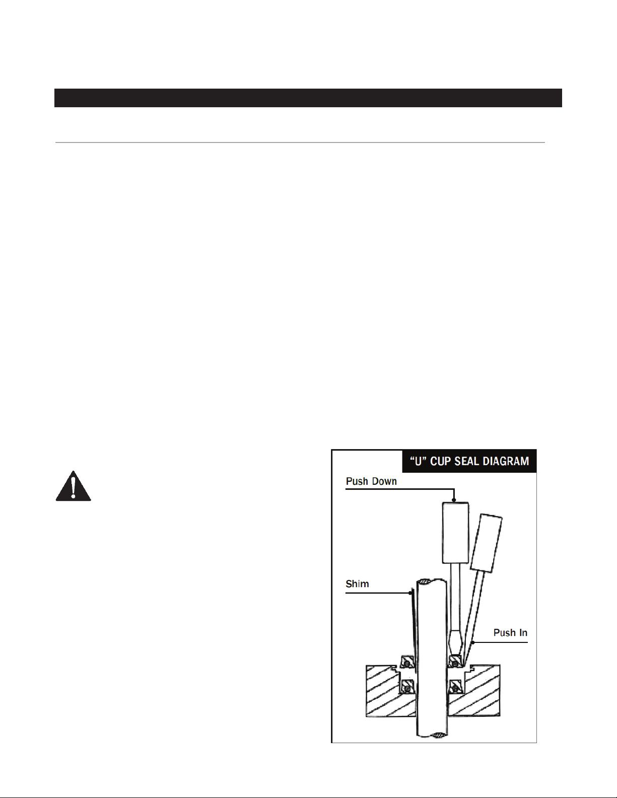
4. Remove the internal snap ring using
snap ring pliers.
5. Remove the thrust washer and the “U” cup seals are
now visible.
6. Using a screwdriver pry out the old seals.
7. Apply a small amount of silicone or grease to the
new “U” cup seals. This will help them slide in the
packing cavity.
8. Put a piece of shim stock into the cavity and put
the “U” cup over it.
CAUTION:
Valve should be depressurized for all
maintenance activities
9. Slide the “U” cup over the stem with shim stock
against the stem. This will let any trapped air out of
the packing cavity.
10. Using two screwdrivers, coax the outer lip of the
"U" cup into the cavity while pressing down on
the top of the "U" cup with the other screwdriver.
Continue to do this all the way around until the
"U" cup is at the bottom of the packing cavity.
11. Repeat this procedure with the second “U” cup.
12. Replace the thrust washer and snap ring.
13. Replace adjustment gland by reversing rst 3 steps.
6
Page 7
MULTIPORT (3-WAY) PLUG VALVE OPERATION AND
MAINTENANCE MANUAL SERIES 604
Plug To Seat Adjustment
PLUG TO SEAT ADJUSTMENT
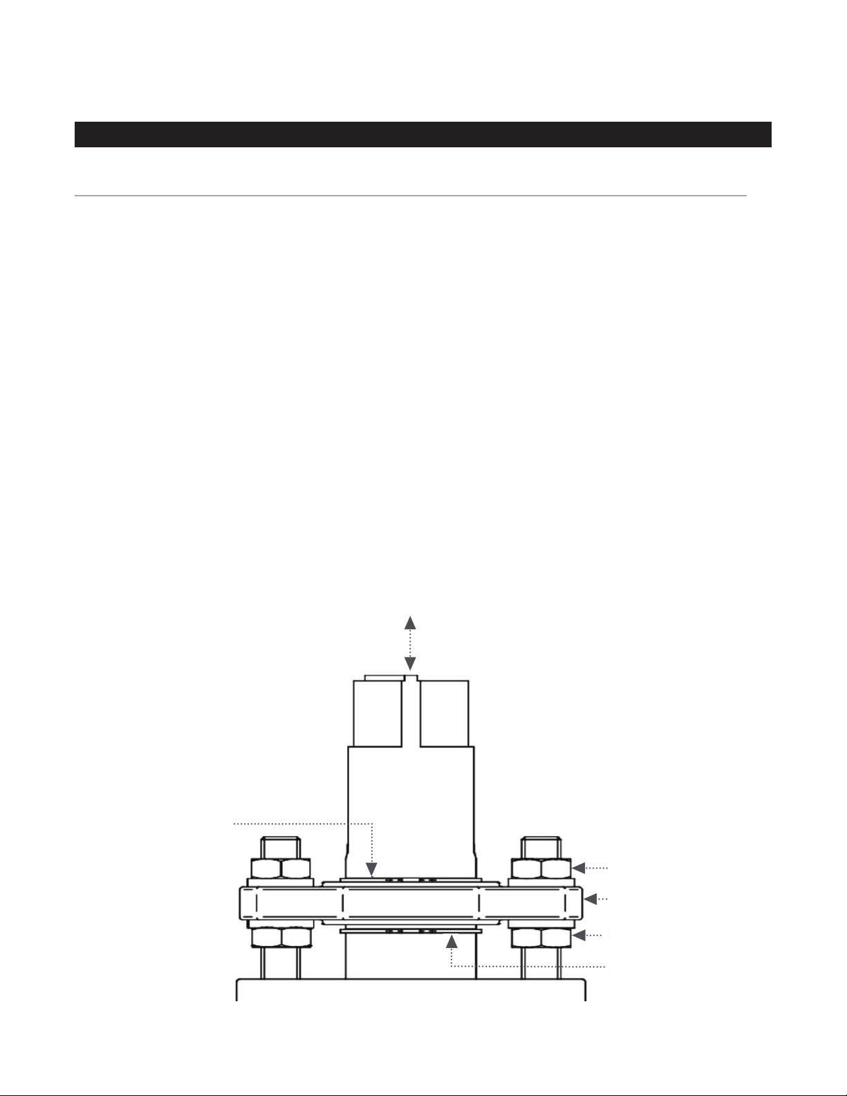
Using the Adjustable Gland arrangement, it is possible to set the vertical position of the plug in the valve seat.
Plug to seat adjustment is factory set to provide the best possible shut off with the least amount of rotating torque.
The Shut-Off condition requires the plug face to be in close contact with the valve body with upstream pressure
applied behind the plug. Should it become necessary to adjust (increase or decrease) the seating force, the
following instructions will apply:
To Decrease Seating Force (Lift Plug)
1. Loosen top gland nuts several turns.
2. Turn bottom gland nuts counterclockwise, each ½ turn at a time until proper plug elevation is reached.
3. Tighten top gland nuts.
To Increase Seating Force (Lower Plug)
1. Loosen bottom gland nuts several turns.
2. Turn top gland nuts clockwise, each ½ turn at a time until proper plug elevation is reached.
3. Tighten bottom gland nuts.
Plug Adjustment
External Snap Ring
Top Gland Nut
Adjusting Gland
Bottom Gland Nut
Internal Snap Ring
7
Page 8

MULTIPORT (3-WAY) PLUG VALVE OPERATION AND
MAINTENANCE MANUAL SERIES 604
Disassembly and Reassembly
DISASSEMBLY
If it becomes necessary to inspect the valve internally or to remove debris and deposits, the valve can be
disassembled without removing the valve body from the pipeline.
Servicing work on the valve should be undertaken by a skilled person using proper tools, slings and a hoist.
Eye protection and gloves should be worn and it may be necessary to wear a mouth and nose mask or a respirator
in extreme circumstances.Refer to the exploded view on page 5 to see the construction of the valve.
• Depressurize the system and isolate each of the pipes connected to the valve. The plug should be rotated so
that it is partially across any two adjacent ports. This will ensure pressure is equalized between the three ports.
Preferably drain the valve and the three pipes before removing the valve bonnet.
• Make a mark on the edge of the valve bonnet and a corresponding mark on the body to ensure the bonnet can
be re-assembled in the same position.
• If an actuator or gearbox is tted then the bonnet, plug, mounting bracket and operator may be removed as a
sub-assembly.
Actuators should be removed using soft slings carefully placed to avoid damage.
Any hand-wheels present must not be used as a convenient point for lifting.
• Loosen the bonnet screws gradually in sequence to ensure there is not a rapid release of residual pressure.
Remove the bonnet screws.
• Using a hoist and sling lift the bonnet and plug assembly clear of the valve and carefully set down.
• Remove the O-ring bonnet seal. Clear out the body of any solid matter and debris.
• Clean the internal tapered seating surface and clean the internal bore of the lower bearing.
• Clean the counter bore in the top of the body. Clean the valve plug and underside of the bonnet.
Ensure the rubber encapsulation on the plug is undamaged and the O-ring sealing area on the bonnet is clean
and undamaged.
REASSEMBLY
• Lightly apply silicone grease to a new O-ring bonnet
seal and place in the counter bore at the top of the
body. Using a hoist, lower the bonnet/ plug assembly
into the body conrming that the previously applied
marks on the body and bonnet are positioned to be in
alignment. Engage the lower trunnion on the plug into
the lower body bearing and carefully allow the bonnet
to locate onto the body.
• Apply grease to the threads of the bonnet screws and
screw them into place nger tight. Remove the sling
and eyebolts from the bonnet.
• Tighten the bonnet screws in a diagonal and
sequential order. The bonnet will achieve metal/
metal contact with the body.
8
Page 9

MULTIPORT (3-WAY) PLUG VALVE OPERATION AND
MAINTENANCE MANUAL SERIES 604
Replacing The Plug
REPLACING THE PLUG
This operation can be carried out without removing the valve from the pipeline. If the valve is tted with a gearbox
or actuator, that must be removed; follow the instructions for removal under section Disassembly on page 8.
Refer to the exploded view on page 5 to see the construction of the valve.
• Depressurize the system and isolate each of the pipes
connected to the valve. The plug should be rotated so
that it is partially across any two adjacent ports. This will
ensure pressure is equalized between the three ports.
Preferably drain the valve and the three pipes before
removing the valve bonnet.
• Make a mark on the edge of the valve bonnet and
a corresponding mark on the body to ensure the
bonnet can be re-assembled in the same position. If
an operator is tted, make alignment marks on the
mounting bracket and bonnet.
• Remove the screws holding the mounting bracket to the
bonnet and lift the operator clear. If a stem adaptor is
tted that should be removed at this time.
• Remove the external snap ring (11) and the nuts (8)
and washers (9). Lift the gland (10) clear of the valve.
Remove the internal snap ring (6). Turn the lower gland
nuts clockwise.
• Remove bonnet screws (5) and lift the bonnet clear of
the valve. If the bonnet sticks, hit the side edge of the
bonnet with a soft hammer to break the seal. It may
be necessary to use a hoist to lift the bonnet from the
valve. If the plug does not disengage from the bonnet,
tap the end of the plug with a soft hammer so the
bonnet can be removed leaving the plug in place in
the body.
• Note the position of the plug face and make an external
mark on the body to denote alignment with the plug
face. Lift the plug from the valve body. For large plugs,
it will be necessary to use a hoist to lift the plug.
• Clean the inside of the body and inspect the lower
bearing (12). Clear any debris from the bearing cavity.
• Turn the bonnet over and inspect and clean the bore of
the upper bearing (13). Clean the underneath surface of
the bonnet paying particular attention to the machined
location for the body.
• Inspect the new plug to ensure there is no damage
to the rubber sealing face. Apply silicone grease to
the lower trunnion and t the new plug into the lower
bearing. Ensure the plug face is aligned with the
temporary marking on the body.
• It is recommended that main seals are replaced during
a major servicing operation. Clean the O-ring seal
location in the body; lightly apply silicone grease to the
new O-ring (3) and carefully t into the body counter
bore location. Remove the existing bonnet U-cup seals
(14) as described on page 6.
• Carefully assemble the bonnet over the stem and
lower onto the valve ensuring that the temporary
markings on the bonnet and body are aligned.
Apply grease to the threads of the bonnet screws
and t - nger tight. Tighten the bonnet screws in a
progressive diagonal fashion.
• Apply grease to both snap ring grooves and re-t the
lower snap ring (6). Apply grease to the bore of the
gland and t the gland over the stem and locate on
the studs, resting on the lower snap ring. Re-t the
upper snap ring (11) and top gland nuts and washers.
Adjust the upper and lower gland nuts until they are
nger tight.
• Where applicable, re-t the operator ensuring the
temporary marking on the bonnet and mounting
bracket are aligned.
• Set the plug position as described on page 7.
9
Page 10

MULTIPORT (3-WAY) PLUG VALVE OPERATION AND
MAINTENANCE MANUAL SERIES 604
Lubrication Schedule & Spare Parts List
LUBRICATION SCHEDULE
The 3-way plug valve is a low maintenance non-lubricated eccentric plug valve. As such there is no required
lubrication for the valve itself.
The manual worm gear operators where applicable are also sealed grease lubricated units and should not
require any type of periodic lubrication. Should the unit need to have the lubricant replaced, it is recommended
that Leahy Wolf Grease L-W 2500 or equivalent grease shall be used.
SPARE PARTS LIST
The Henry Pratt 3-way plug valve is a long life valve and does not require stocking spare parts.
10
Page 11
MULTIPORT (3-WAY) PLUG VALVE OPERATION AND
MAINTENANCE MANUAL SERIES 604
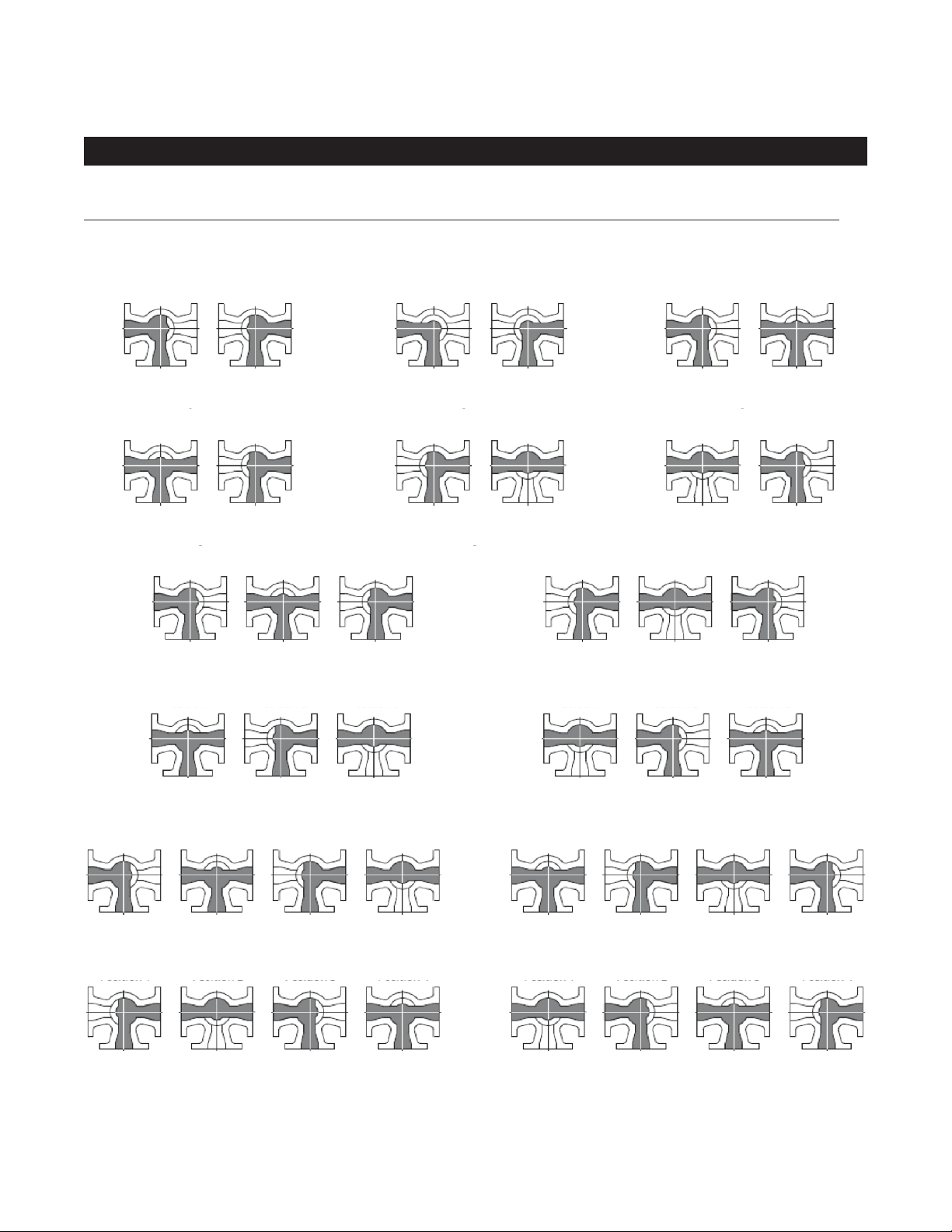
PRATT® MULTI-PORT (3-WAY) PLUG VALVE PORT POSITIONS
Port Positions Viewed from Above
Plug Valve Port Positions
Position 1
3 way, 3 port, 180° turn
Style A180
Position 1
3 way, 3 port, 90° turn
Position 1
Position 1
Position 2
Position 2
Style D
Position 2
3 way, 3 port, 180° turn
Position 2
Style G
Position 3
Position 1
3 way, 2 port, 90° turn
Style A90
Position 1
3 way, 3 port, 90° turn
Position 2
Position 2
Style E
Position 1
Position 1
Position 1
3 way, 3 port, 90° turn
Style C
Position 1
3 way, 3 port, 90° turn
Style F
Position 2Position 3
3 way, 3 port, 180° turn
Style H
Position 2
Position 3
Position 2
Position 2
Position 3
3 way, 3 port, 180° turn
Position 1
Position 1
Position 2
3 way, 3 port, 270° turn
Style K
Position 2
3 way, 3 port, 270° turn
Style M
* Requires Double-Style Plug
Style I
Position 3
Position 3
Position 4
Position 4
11
Position 1
Position 1
3 way, 3 port, 180° turn
Style J
Position 2
3 way, 3 port, 270° turn
Position 2
3 way, 3 port, 270° turn
Position 3
Style L
Position 3
Style N
Position 4
Position 4
Page 12

MULTIPORT (3-WAY) PLUG VALVE OPERATION AND
MAINTENANCE MANUAL SERIES 604
TROUBLESHOOTING
Wrench Operated Plug Valve
Problem Cause Solution
Valve will not open • broken or misadjusted torque collar
• obstruction in line
• excessive line pressure
• elastomer damage
Valve will not close • broken or misadjusted torque collar
• obstruction in line
• excessive line pressure
• elastomer damage
Valve will not shut off ow • improper stop adjustment
• obstruction in line
• excessive line pressure
• elastomer damage
Valve leaks at plug stem • damaged “U” cup seal • replace “U” cups
• adjust or replace torque collar
• remove obstruction
• reduce pressure
• replace plug
• adjust or replace torque collar
• remove obstruction
• reduce pressure
• replace plug
• adjust closed stop
• remove obstruction
• reduce pressure
• replace plug
Troubleshooting
Gas Operated Plug Valve
Problem Cause Solution
Valve will not open • bent input shaft
• obstruction in line
• excessive line pressure
• elastomer damage
Valve will not close • bent input shaft
• obstruction in line
• excessive line pressure
• elastomer damage
Valve will not shut off ow • improper stop adjustment
• obstruction in line
• excessive line pressure
• elastomer damage
Valve leaks at plug stem • damaged “U” cup seal • replace “U” cups
• replace worn shaft
• remove obstruction
• reduce pressure
• replace plug
• replace worn shaft
• remove obstruction
• reduce pressure
• replace plug
• adjust closed stop
• remove obstruction
• reduce pressure
• replace plug
Actuated Plug Valve
Problem Cause Solution
Valve will not close/open • no power source
• improper signal
• burned out or impaired component
• check incoming power source
and/or replace fuses
• check actuating signal sequence
• check and repair or replace motor or
relay devices
Valve will not shut off ow • improper stop adjustment
• actuator torques out
12
• re-set limit switch
• check for obstructions in valve
Page 13
MULTIPORT (3-WAY) PLUG VALVE OPERATION AND
MAINTENANCE MANUAL SERIES 604
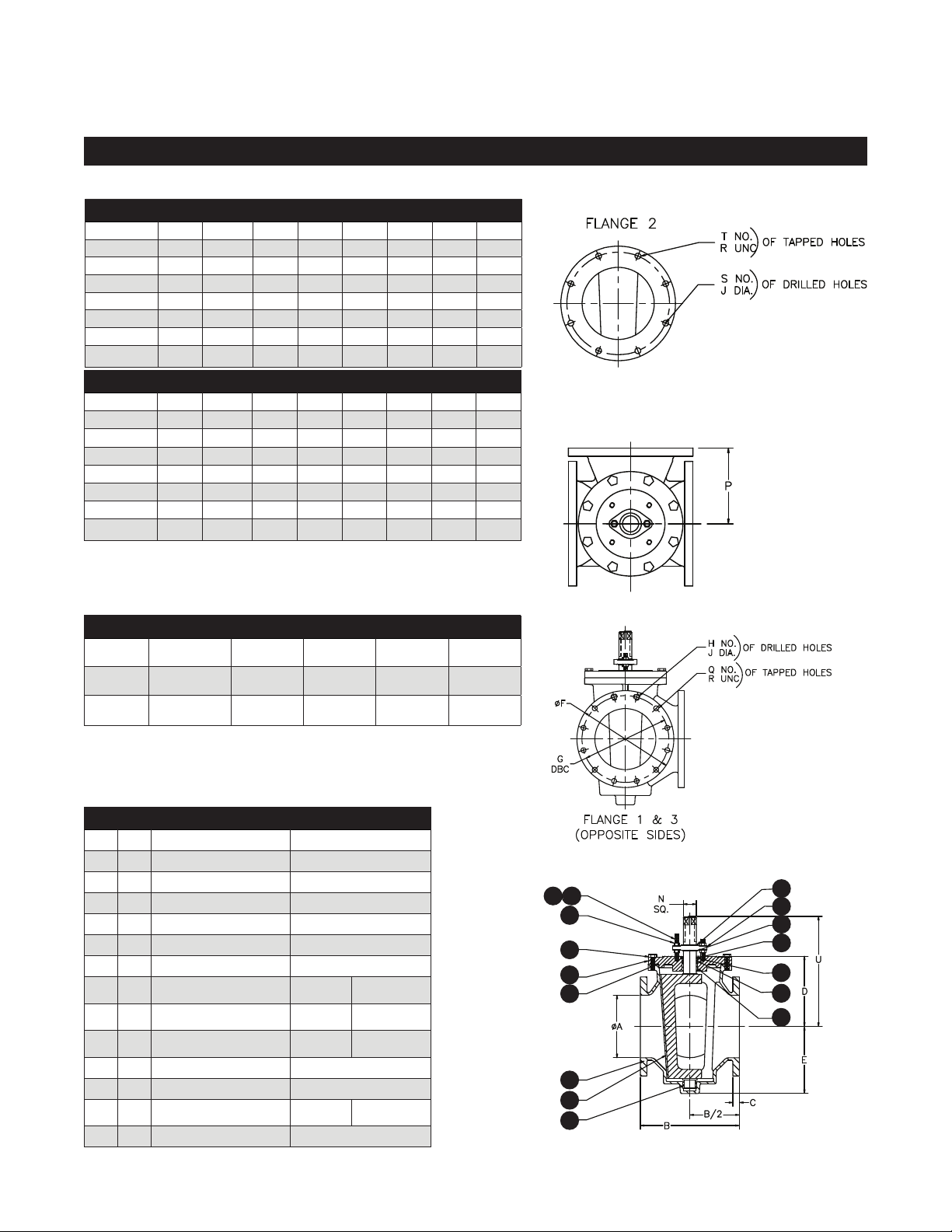
3”-16” Three-Way Plug Valve with Wrench Operated
VALVE SIZE A B C D E F G H
3 3 8 0.75 4.96 4.81 7.50 6.00 4
4 4 9.88 1.00 6.94 5.94 9.00 7.50 6
6 6 11.63 1.00 8.06 7.06 11.00 9.50 6
8 8 13.88 1.13 11.75 10.94 13.50 11.75 4
10 10 16.75 1.19 11.75 10.94 16.00 14.25 12
12 12 19.00 1.25 13.50 12.88 19.00 17.00 12
14 14 21.00 1.38 14.38 14.19 21.00 18.75 10
16 16 23.75 1.44 15.06 14.75 23.50 21.25 16
VALVE SIZE J N P Q R S T U
3 0.75 1.00 5.50
4 0.75 2.00 6.50 2 0.63 8
6 0.88 2.00 8 2 0.75 8
8 0.88 2.00 9 4 0.75 8
10 1 2.00 11
12 1 2.00 11.56
14 1.13 N/A (1) 12.50 2 1.00 8 4 18.31
16 1.13 N/A (1) 15.13
Notes:
1. 14” & 16” Require adapter to be lever operated.
─ ─
─ ─
─ ─
─ ─
4
12
8 4 19.50
16
11.00
─
12.75
─
12.00
─
17.75
─
17.75
─
20.69
─
THREE-WAY VALVE PORT POSITION STYLES
90° A90
180° A180
270°
─
□
□
□
C
G
K
□
□
□
D
H
L
□
□
□
E
I
M
□
□
□
F
J
N
Please see Pratt multiport plug valve catalogue page 5 for valve
patterns of the three-way valve port positions
Item QTY Description Material
1 1 Body Cast Iron
2 1 Cap Cast Iron
3 1 Plug Eslatomer As Spec. Ductile Iron
4 2 Sleeve Bearing Stainless Steel
5 3 Snap Ring Spring Steel
6 2 U Cup Seal Elastomer As Spec.
7 1 “O” Ring Elastomer As Spec.
8 AR H.H. Cap Screw
9 2 Stud
10 4 Jam Nut
11 1 Retaining Ring Steel
14 1 Seal Ret. Ring Brass
15 AR Flatwasher
16 1 Gland Ductile Iron
Steel □Stn. Steel
□
Steel □Stn. Steel
□
Steel □Stn. Steel
□
Steel □Stn. Steel
□
□
□
□
15
10
9
8
2
7
1
3
4
5
16
5
11
5
6
4
13
Page 14
MULTIPORT (3-WAY) PLUG VALVE OPERATION AND
MAINTENANCE MANUAL SERIES 604
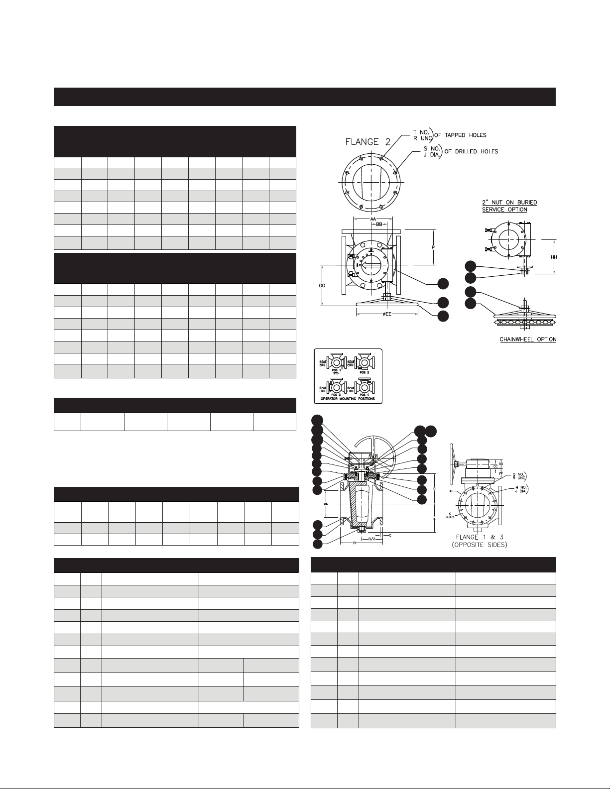
3”-16” Three-Way Plug Valve with 90° Turn Gear Operator & Handwheel or Nut or Chainwheel
90°
VALVE
Gear
SIZE
Size
3 M3 3 8 0.75 4.96 4.81 7.50 6.00
4 M8 4 9.88 1.00 6.94 5.94 9.00 7.50
6 M8 6 11.63 1.00 8.06 7.06 11.00 9.50
8 M8 8 13.88 1.13 11.75 10.94 13.50 11.75
10 M8 10 16.75 1.19 11.75 10.94 16.00 14.25
12 M8 12 19.00 1.25 13.50 12.88 19.00 17.00
14 M8 14 21.00 1.38 14.38 14 .19 21.00 18.75
16 M8 16 23.75 1.44 15.06 14.75 23.50 21.25
90°
VALVE
Gear
SIZE
Size
3 M3 4 0.75 5.50
4 M8 6 0.75 6.50 2 0.63 8
6 M8 6 0.88 8 2 0.75 8
8 M8 4 0.88 9 4 0.75 8
10 M8 12 1 11
12 M8 12 1 11.56
14 M8 10 1.13 12.50 2 1.00 8 4
16 M8 16 1.13 15.13
A B C D E F G
H J P Q R S T
─ ─
─ ─
─ ─
─ ─
4
12
8 4
16
─
─
─
─
─
─
107
107
106
107
109
107
108
THREE-WAY VALVE PORT POSITION STYLES
90° A90
□
C
□
D
□
E
□
F
□
Please see Pratt multiport plug valve catalogue page 5
for valve patterns of the three-way valve port positions
90° Gear Option
Gear
Size
Item QTY Description Material
*Only on 3* Vavle is bracket and coupler used.All the others use only a bracket
AA BB CC DD EE FF GG HH
M3 7.00 2.56 1.50 3.56 6.00 6.00 9.50 8.00
M8 11.25 4.63 2.00 4.53 4.00 4.00 11.63 10.00
1 1 Body Cast Iron
2 1 Plug Ductile Iron
3 1 “O” Ring Elastomer As Spec.
4 1 Cap Cast Iron
5 2 Bearing Stainless Steel
6 2 Snap Ring Spring Steel
7 1 Gland Ductile Iron
8 4 Flatwasher
9 2 Stud
10 4 Jam Nut
11 1 Retaining Ring Steel
12 AR Cap Screw
□
□
□
□
Steel
Steel
Steel
Steel
□
□
□
□
Stn. Steel
Stn. Steel
Stn. Steel
Stn. Steel
103
101
102
10
12
104 105
9
8
4
3
1
2
5
Item QTY Description Material
13 1 Seal Ret. Ring Brass
14 2 U Cup Seal Elastomer As Spec.
50 1 Gear
101 1 Key Steel
102 1 Bracket Steel
*103 1 Coupling Steel
104 AR Cap Screw Steel/Zinc
105 AR Lock Washer Steel/Zinc
106 1 Handwheel Ductile Iron
107 1 Spring Pin Steel
108 1 Chainwheel Ductile Iron
109 1 2" Nut Ductile Iron
6
7
6
11
13
14
5
—
of Tapped
Holes
of Drilled
Holes
14
Page 15
MULTIPORT (3-WAY) PLUG VALVE OPERATION AND
MAINTENANCE MANUAL SERIES 604
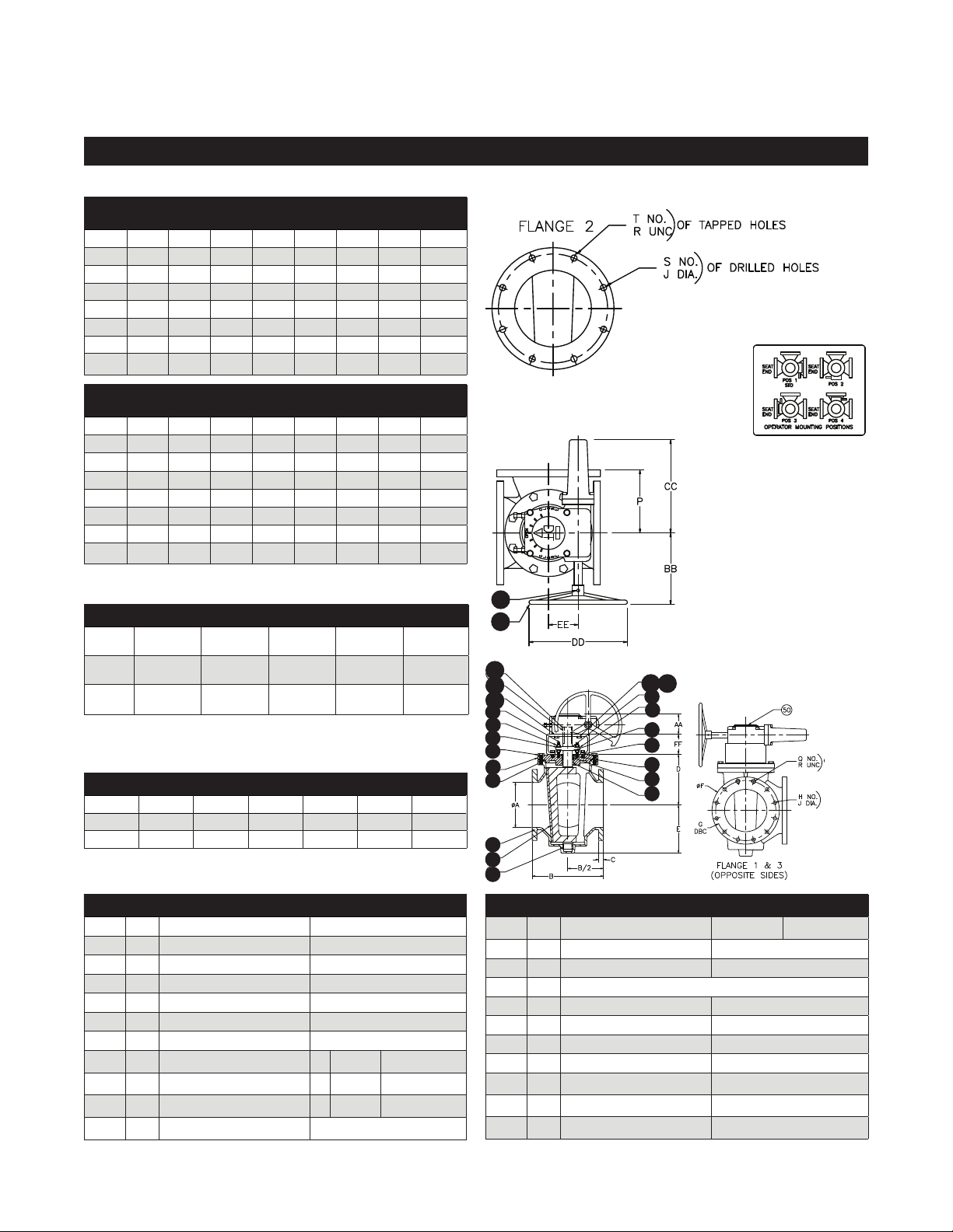
3”-16” Three-Way Plug Valve with 180°, 270°, & 360° Turn Gear Operator & Handwheel
VALVE
Gear
SIZE
Size
3 DT03 3 8.OO 0.75 4.96 4.81 7.50 6.00
4 DT21 4 9.88 1.00 6.94 5.94 9.00 7.50
6 DT21 6 11.63 1.00 8.06 7.06 11.00 9.50
8 DT21 8 13.88 1.13 11.75 10.94 13.50 11.75
10 DT21 10 16.75 1.19 11.75 10.94 16.00 14.25
12 DT21 12 19.00 1.25 13.50 12.88 19.00 17.00
14 DT21 14 21.00 1.38 14.38 14.19 21.00 18.75
16 DT21 16 23.75 1.44 15.06 14.75 23.50 21.25
VALVE
Gear
SIZE
Size
3 DT03 4 0.75 5.50
4 DT21 6 0.75 6.50 2 0.63 8
6 DT21 6 0.88 8.00 2 0.75 8
8 DT21 4 0.88 9.00 4 0.75 8
10 DT21 12 1.00 11.00
12 DT21 12 1.00 11.56
14 DT21 10 1.13 12.50 2 1.00 8 4
16 DT21 16 1.13 15.13
A B C D E F G
H J P Q R S T
─ ─
─ ─
─ ─
─ ─
4
12
8 4
16
─
─
─
─
─
─
THREE-WAY VALVE PORT POSITION STYLES
180° A
270° K
360°
K
Please see Pratt multiport plug valve catalogue page 5 for
valve patterns of the three-way valve port positions
AA BB CC DD EE FF
DT03 2.59 6.25 5.50 6.00 1.75 6.00
DT21 3.54 9.27 10.96 12.00 3.63 4.00
Item QTY Description Material
1 1 Body Cast Iron
2 1 Plug Elastomer As Spec. Ductile Iron
3 1 “O” Ring Elastomer As Spec.
4 1 Cap Cast Iron
5 2 Bearing Stainless Steel
6 2 Snap Ring Spring Steel
7 1 Gland Ductile Iron
8 4 Flatwasher
9 2 Stud
10 4 Jam Nut
11 1 Retaining Ring Steel
*Only on 3* Vavle is bracket and coupler used.All the others use only a bracket
□
□
□
G
L
L
□
□
□
Gear Size
H
M
M
□
□
□
□
□
□
I
N
N
Steel
Steel
Steel
□
□
□
□
□
□
J
□
─
□
─
□
Stn. Steel
Stn. Steel
Stn. Steel
103
101
102
10
12
9
8
4
3
1
2
5
107
106
104
105
6
7
6
11
13
14
5
Item QTY Description Material
12 AR Cap Screw
13 1 Seal Ret. Ring Brass
14 2 U Cup Seal Elastomer As Spec.
50 1 Dynatorque DT03/DT21 Gear
101 1 Key Steel
102 1 Bracket Steel
*103 1 Coupling Steel
104 AR Cap Screw Steel/Zinc
105 AR Lock Washer Steel/Zinc
106 1 Handwheel Ductile Iron
107 1 Spring Pin Steel
□
Steel
□
Stn. Steel
of Tapped
Holes
of Drilled
Holes
15
Page 16

MUELLER® | ECHOLOGICS® | HYDRO GATE® | HYDRO-GUARD® | HYMAX® | JONES® | KRAUSZ® | MI.NET® | MILLIKEN®
PRATT® | PRATT INDUSTRIAL® | SINGER® | U.S. PIPE VALVE & HYDRANT
1.800.423.1323 – www.prattvalve.com – [email protected]
INTERNATIONAL – 1.423.490.9555 – www.mueller-international.com – [email protected]
Mueller refers to one or more of Mueller Water Products, Inc., a Delaware corporation (“MWP”), and its subsidiaries. MWP and each of subsidiaries are legally separate and independent entities when
providing products and services. MWP does not provide products or services to third parties. MWP and each of its subsidiaries are liable only for their own acts and omissions and not those of each other.
MWP brands include Mueller®, Echologics®, Hydro Gate®, Hydro-Guard®, Hymax®, Jones®, Krausz®, Mi.Net®, Milliken®, Pratt®, Pratt Industrial®,
Singer®, and U.S. Pipe Valve & Hydrant. Please see www.muellerwp.com/about to learn more.
Copyright © 2020 Henry Pratt Company, LLC. All Rights Reserved. All Rights Reserved. The trademarks, logos and service marks displayed in this
document are the property of Mueller Water Products, Inc., its afliates or other third parties. Products above marked with a section symbol (§) are subject
to patents or patent applications. For details, visit www.mwppat.com. These products are intended for use in potable water applications. Please contact
your Mueller Sales or Customer Service Representative concerning any other application(s).
16
 Loading...