

Prastel MEGAPROX1-P User Manual
3 paires 6/10
° - 100 m max
B
C
D
E
F
F
F
Notice d’installation / Installation procedure
Modèle TTL (Clock&Data / Wiegand) (ETSI)
Modèle RS232 (ETSI)
Modèle RS485 (ETSI)
Modèle TTL (Clock&Data / Wiegand) (FCC)
Modèle RS232 (FCC)
Modèle RS485 (FCC)
Alimentation : +9 Vdc à +36 Vdc (+12 Vdc Typique)
Consommation : 1A sous +12 Vdc
Communication : RS485 (L+ & L-)
RS232 (TD & RD)
TTL (Wiegand / Clock & Data)
Raccordement : Bornier débrochable à vis 14 points
Pas de 3.80 mm
Température de fonctionnement : -20 °C / +55°C
-4,00 °F / +131,00°F
Indice de protection : IP65
Puce lue : EPC1 Gen2 (ISO 18000-6C) 96 bits max.
Relais: 1 A max sous 30 Vdc.
Entrée TOR : circuit anti-rebond pour connexion détection de
LEDS : Deux lignes pilotent deux couleurs parmi les 7
Arrachement : Contacteur interne permettant la détection de
Utiliser du câble multiconducteur blindé par tresse, reliée à la masse du concentrateur.
Déport max RS485 : 1000 m. à 9600 bauds (SYT2 6/10 ° conseillé)
Déport max RS232 : 15 m. (SYT2 6/10 ° conseillé)
Wiegand / Clock & Data :
Pour plus d’informations concernant le dialogue avec le lecteur, veuillez consulter la
spécification du protocole.
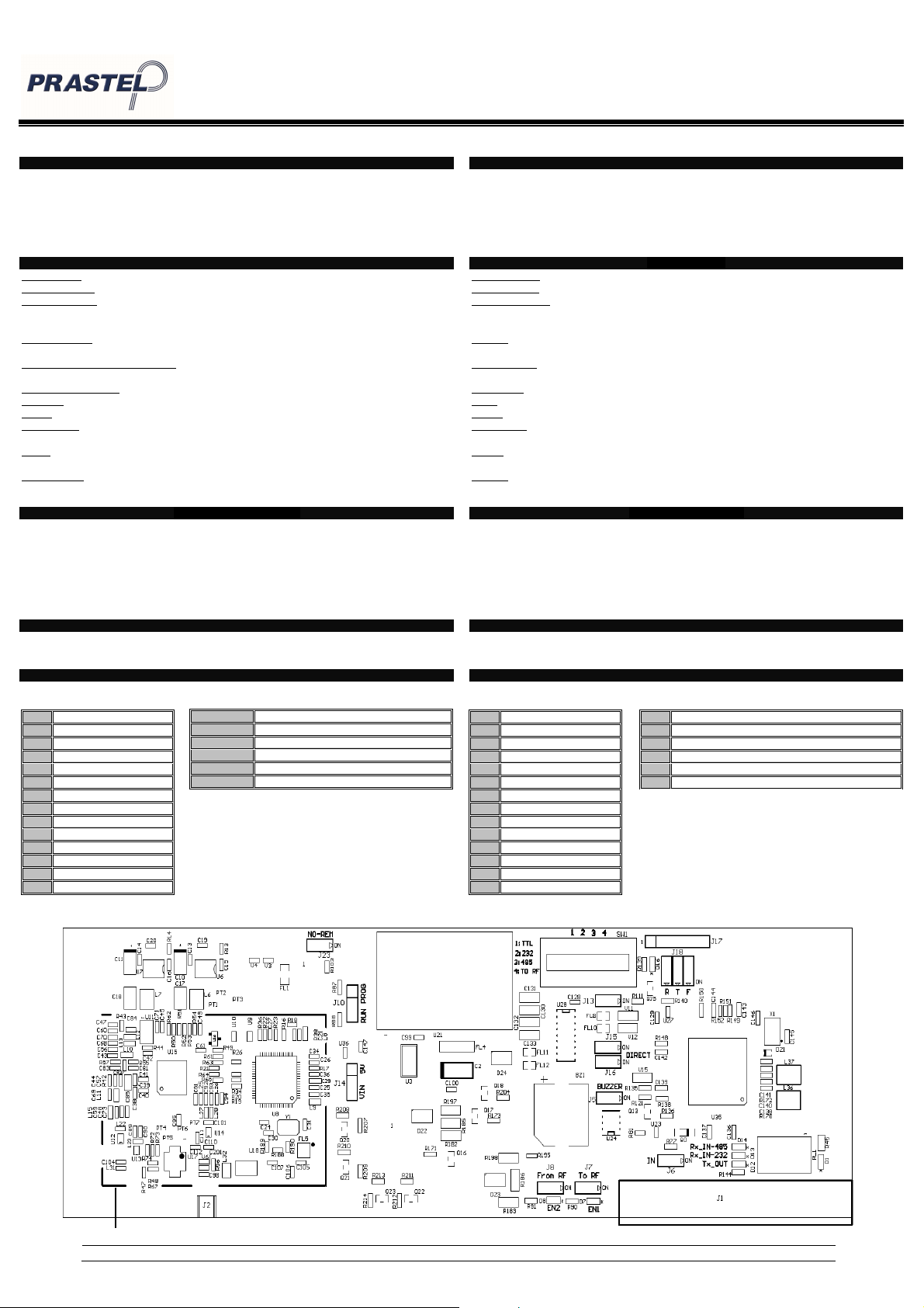
Les différents composants et les connexions du lecteur sont ci-dessous.
1 GND
2 Alimentation
3 IN1
4 GND
5 L+/TD/Data/D1
6 L-/RD/Clock/D0
7 GND
8 LED1
9 LED2
10 GND
11 COM
12 NO
13 BUZ
14 GND
passage
disponibles.(par défaut : Led1 : rouge; Led2 :vert)
l’ouverture du capot.(configurable par tag)
1 paire 6/10° - 30 m max 1 paire 9/10° - 50 m max
2 paires 6/10° - 60 m max 2 paires 9/10° - 100 m max
Références des produits
Caractéristiques
Type de câble préconisé
Communication
Vue générale
A Switch (SW1)
B Résistance de fin de lignes RS485 (J13)
C Commutateur de filtrage (J18 F)
D Buzzer (J5)
E IN1 (J6)
F LEDS de visualisation (D22-D23-D24)
RS232 (TD & RD)
Lecteur UHF / UHF Reader: MEGAPROX1-P
TTL Model (Clock&Data / Wiegand) (ETSI)
RS232 Model (ETSI)
RS485 Model (ETSI)
TTL Model (Clock&Data / Wiegand) (FCC)
RS232 Model (FCC)
RS485 Model (FCC)
Power supply: +9 Vdc up to +36 Vdc (+12 Vdc Typical)
Consumption: 1A under +12 Vdc
Communication: RS485 (L+ & L-)
TTL (Wiegand / Clock & Data)
Pin out: Connector 14 points
Thread 3.80 mm / 0.149 in
Temperature: -20 °C / +55°C
-4.00 °F / +131.00°F
Protection:
Chip: EPC1 Gen2 (ISO 18000-6C) 96 bits max.
Relay: 1 A max under 30 Vdc.
TOR input: Anti-bounce circuit for connection crossing
detection
LEDS: Two colors available among 7 available ( default:
Led1: red; Led2: green)
Tearing: Switch for detecting the opening of the cover.
(configured with configuration tag)
Use a multi-conductor cable, pair shielded.
Max length RS485: 1000 m / 3 280.84 ft at 9600 bps (SYT2 AWG24 Recommended)
Max length RS232: 15 m / 49.21 ft. (SYT2 AWG24 recommended)
Wiegand / Clock & Data:
More details about reader’s communication are available in the protocol specification
The different components and the connexions are represented below.
1 pair AWG24 - 98,43 ft / 30 m max 1 pair AWG35 - 164,04 ft / 50 m max
2 pairs AWG24 - 196,85 ft / 60 m max 2 pairs AWG35 - 328,08 ft / 100 m max
3 pairs AWG24 -328,08 ft / 100 m max
Products references
Characteristics
IP65
Recommended cables
Communication
Overview
1 GND
2 Power Supply
3 IN1
4 GND
5 L+/TD/Data/D1
6 L-/RD/Clock/D0
7 GND
8 LED1
9 LED2
10 GND
11 COM
12 NO
13 BUZ
14 GND
A Switch (SW1)
B End of line resistor RS485 (J13)
C Filtering switch
D Buzzer (J5)
E IN1(J6)
F Led of visualization(D22-D23-D24)
A
1 2 3 4 5 6 7 8 9 10 11 12 13 14
© PRASTEL 2013 – NI-MEGAPROX1-P – Ed. 05/04/2013
X
oct
ets
X
bytes
Notice d’installation / Installation procedure
Initialisation du lecteur de 12 secondes à la mise sous tension.
A la fin de l’initialisation, le lecteur recherchera un tag de configuration sur l’antenne
Le lecteur peut gérer une anticollision à hauteur de 4 tags.
Si plusieurs tags sont présents dans le même champ, un délai d’environ 200 ms
Le cycle de scan, variant suivant le nombre de tags présents, est au plus rapide de
Un tag lu provoque un clignotement de la Led orange de visualisation, un bip sonore
Filtrage (C) : Cette option permet, si le commutateur est placé sur On, d’utiliser le
Choix du protocole de communication (A) : Il est possible de configurer la sortie du
Résistance de fin de lignes (B):A utiliser lors d’une communication RS485 lorsque la
Voie IN1 (E) : Lorsque le commutateur J6 est positionné sur OFF, le lecteur
Buzzer (D) : Le buzzer émet un bip sonore lors de chaque lecture. Il est possible de
Protocoles TTL (Wiegand & ISO2)
Protocoles Série (RS232 & RS485)
Détail du protocole série (configurable, à préciser lors de la commande)
Chaque partie (hormis Data Frame) peut être activée ou désactivée dans l’envoi de la
trame. LRC calculée sur Data Frame (XOR)
D’autres options de configurations sont accessibles (à préciser lors de la commande) :
La tension d’alimentation aux bornes du lecteur doit être comprise entre +9 Vdc et
Eloigner autant que possible le lecteur des câbles de transmission informatique ou
Eloigner les lecteurs entre eux d’environ deux mètres et éviter de croiser les champs
Utiliser une alimentation filtrée et régulée.
Régler l’antenne de façon à être parallèle aux identifiants.
Eviter de regarder la Led Haute luminosité capot ouvert.
Serrer modérément les vis de fixation du capot afin de ne pas écraser le joint
Il est recommandé d’utiliser une alimentation 2.5 A à 3 A minimum.
Il est important pour l’utilisateur de se positionner à au moins 25cm d’une antenne
•
Tous les paramètres sont pris à ce moment (voir §Configuration de la
carte interface).
•
La led orange de visualisation est allumée.
pendant 4 secondes.
•
Clignotement de la led de visualisation.
•
Si un badge de configuration est présenté sur l’antenne, la led verte
clignote rapidement 6 fois signalant ainsi la prise en compte du badge.
sépare l’envoi de chaque identifiant en TLL, en RS232 envoi direct en série.
100 ms.
du buzzer ainsi que l’activation du Relais 1 pendant 200 ms.
mode filtrage. Le lecteur ne lira qu’une seule fois l’identifiant présent dans le champ
selon un temps défini à la configuration du lecteur (6, 9, 12 ou 15 secondes – 6 par
défaut). Si la fonction est désactivée, le lecteur émettra un code pour un même
identifiant toutes les 200 ms environ.
lecteur entre différents formats (TTL, RS232, RS485 ou OFF – à préciser lors de la
commande). Les structures des trames peuvent également être modifiées (Choix
Clock&Data / Wiegand, structure des trames RS232 / RS485 – à préciser lors de la
commande, pour plus d’informations se référer au § « Protocole »).
distance de câbles de données approche ou est supérieure à 100 m et que la
communication se dégrade (signaux non francs, erreurs de trames etc..).
n’activera la lecture sur l’antenne uniquement si un 0 Vdc est présent sur l’entrée
IN1 (activation pendant la période de présence du 0 Vdc + 5 secondes
supplémentaires après le changement d’état sur l’entrée IN1). Si le commutateur J6
est positionné sur On, le lecteur scannera continuellement.
l’inhiber en positionnant le commutateur J5 (placé au-dessus du buzzer) sur la
position OFF.
•
ISO2 (Clock & Data) – Décimal (7 octets max).
•
Wiegand avec LRC – Hexadécimal (12 octets max).
•
Wiegand sans LRC – Hexadécimal (12 octets max).
•
RS232 (trame configurable – à préciser lors de la commande).
•
RS485 (trame configurable – à préciser lors de la commande).
•
Sortie Hexadécimale ou Décimale (option mode ASCII ou normal)
Si le mode ASCII est activé, la taille des données du tag lu sera doublée.
•
Empaquetage de la trame
1 octet Données du Tag x 1 octet 1 octet 1 octet 1 octet
STX Data Frame LRC 0x0D 0x0A ETX
•
Lecture inversée ou non inversée
•
Temps de filtrage
•
Zéros non-significatifs compris dans la trame ou exclus.
+36 Vdc.
d’origine de puissance (secteur ou Haute Tension). Les perturbations qu’ils peuvent
engendrer peuvent varier en fonction de leur puissance de rayonnement et de leur
proximité avec les lecteurs.
simultanément de plusieurs lecteurs.
d’étanchéité.
en fonctionnement (distance minimale d’exposition)
Fonctionnement
Configuration de la carte interface
Protocole
1 octet
01 Données du Tag x
Recommandations
© PRASTEL 2013 – NI-MEGAPROX1-P – Ed. 05/04/2013
Lecteur UHF / UHF Reader: MEGAPROX1-P
When the reader is switched on, he initializes itself for 12 seconds.
At the end of the initialization, the reader will look for a configuration tag on the
Anticollision up to 4 tags.
If there are several tags in front of the reader, it will send the codes one by one with
The cycle of a scan varies according the number of tags present in front of the
When the reader reads a tag, orange led of visualization, buzzer and Relay 1 are
Filtering (C): If the switch Filtering (N) is On, the reader won’t read the same tag
Choice of the communication (A): It is possible to choose the kind of
End of line resistor (B): Must be fitted (on RS485 connection) if the distance
Lane IN1 (E): If the switch J6 (E) is on the position OFF, the reader will activate
Buzzer (D): The buzzer is activated when the reader reads a tag. To turn it off,
TTL Protocol (Wiegand & ISO2)
Serial Protocols (RS232 & RS485)
Detail of serial protocol (customizable, please state when ordering)
1 byte Lane 1 + Data of the Tag x 1 byte 1 octet 1 octet 1 octet
Each part of the frame (without Data Frame) could be activated or deactivated when it’s
sent. Checksum is calculated on Data Frame (XOR)
There are other options available (please state when ordering) :
The power supply on the connector of the reader must be +9 Vdc min.
Move away as many as possible the cables of power and computer
Move away the readers between them about two meters and avoid
Use a filtered and regulated power supply.
Adjust the position of the reader in order to be parallel to the tags.
Do not look the Led of visualization with the cover opened.
Do not clamp strongly the screws of fixation of the cover to not crush
Do not make loop with the cable of the antenna.
Respect a radius of curvature (15 cm).
A power supply which provides 2.5 A to 3 A min. is required.
For a safe exposure, please take care that the distance between the
•
All parameters are taken into account at this moment (refer to
§Configuration of the interface board).
•
The orange led of visualization is lighted.
antenna for 4 seconds.
•
The green led of visualization will blink..
•
If there is a configuration tag in front of the main reader’s antenna, the
green led of visualization will blink 6 times.
a delay of 200 ms.
antenna. The fastest is 100 ms.
activated one time for 200 ms.
on the RF Field according the time defined in order (6, 9, 12 or 15 seconds).
Otherwise (switch on OFF), the reader will reemit the same code without
filtering.
communication (TTL, RS232, RS485 or OFF – please state when ordering).
The structure of the frame can also be changed (choice: Clock&Data / Wiegand,
RS232 / RS485 – please state when ordering, for more information please refer
§ « Protocol »).
between the controller and the reader is close to or more than 100 meters or on
bad communication (polluted signals, frame errors etc...).
the RF field only if there is a 0 Vdc on the input IN1 plus 5 additional seconds. If
the switch is on position ON, the RF field will be continuously activated.
place the switch J5 located just close to the buzzer on position OFF.
•
ISO2 (Clock & Data) – Decimal (7 bytes max).
•
Wiegand with checksum – Hexadecimal (12 bytes max).
•
Wiegand with checksum – Hexadecimal (12 bytes max).
•
RS232 (frame configurable – please state when ordering).
•
RS485 (frame configurable – please state when ordering).
•
Hexadecimal or Decimal output (ASCII Mode option or normal mode).
1 byte
If the ASCII mode is activated, the size of the tag’s data will be doubled.
•
Structure of the frame
STX Data Frame Checksum 0x0D 0x0A ETX
•
Reversed reading
•
Filtering time
•
No leading zeros
up to +36 Vdc max. (+12 Vdc Typical).
(Ex: RJ45, sector, etc...).
crossing the fields of several readers.
the joint of waterproof quality.
user(s) and the antenna(s)has to be minimum 25cm.
Configuration of the interface board
01 Data of the Tag x
Operating mode
Protocol
Recommendations
 Loading...